towards reconstructing fingerprints from minutiae...
TRANSCRIPT

Towards Reconstructing Fingerprints From Minutiae Points
Arun Rossa, Jidnya Shaha and Anil K. Jainb
a West Virginia University, Morgantown, WV, USA.b Michigan State University, East Lansing, MI, USA.
ABSTRACT
We show that minutiae information can reveal substantial details such as the orientation field and the class of theassociated fingerprint that can potentially be used to reconstruct the original fingerprint image. The proposedtechnique utilizes minutiae triplet information to estimate the orientation map of the parent fingerprint. Theestimated orientation map is observed to be remarkably consistent with the underlying ridge flow. We nextdiscuss a classification technique that utilizes minutiae information alone to infer the class of the fingerprint.Preliminary results indicate that the seemingly random minutiae distribution of a fingerprint can reveal importantclass information. Furthermore, contrary to what has been claimed by several minutiae-based fingerprint systemvendors, we demonstrate that the minutiae template of a user may be used to reconstruct fingerprint images.
1. INTRODUCTION
Most biometric systems do not store the raw biometric data in its entirety but rather extract a salient set offeatures (known as a template) from the biometric data of a user. Since the template, by definition, is a compactdescription of the biometric sample, it is not expected to reveal significant information about the original data.Therefore, template-generation algorithms are typically assumed to be one-way algorithms. However, Adler1 hasdemonstrated that a face image can be regenerated from a face template using a “Hill Climbing Attack”. Heemployed an iterative scheme to reconstruct a face image using a face verification system that releases matchscores. The algorithm first selects an estimate of the target face from a local database comprising of a fewfrontal images by observing the match score corresponding to each image. An eigen-face (computed from thelocal database) scaled by 6 different constants is added to this initial estimate resulting in a set of 6 modifiedface images which are then presented to the verification system. The image resulting in an improved match scoreis retained and this process is repeated in an iterative fashion. Within a few thousand iterations, an image thatcan successfully masquerade as the target face image is generated. The salient feature of this algorithm is thatit does not require any knowledge of either the matching technique or the structure of the template used bythe authentication system. The algorithm was successfully tested on 3 well known commercial face recognitionsystems. This type of masquerade attack can be easily extended to other biometric modalities as illustratedby Hill2 who proposed a method for creating a digital fingerprint artefact from a minutiae template. Hill alsodevised a simple scheme to predict the shape (class) of the fingerprint using the minutiae template.
In this work we develop a technique for reconstructing fingerprints using minutiae information alone. Ourtechnique is significantly different from the one proposed by Hill both in its approach as well as its scope. Weextract a set of features from the minutiae template in order to infer both the orientation map and the class
of the associated fingerprint. We then use Gabor-like filters to reconstruct fingerprints using the orientationinformation. Experiments conducted on the NIST-4 database indicate the efficacy of the proposed algorithmand suggests its potential in providing insights into the nature of the minutiae distribution for different classesof fingerprint.
Further author information: (Send correspondence to A. Ross)A. Ross: [email protected]. Shah: [email protected]. K. Jain: [email protected]

1.1. Fingerprint minutiae
A fingerprint is a smoothly flowing pattern of alternating ridges and valleys. The ridges do not flow continuouslybut rather display various types of imperfections known as minutiae (minor details in fingerprints). At the timeof enrollment in a fingerprint system, important minutiae information (typically, positions of ridge endings andbifurcations, and the associated orientations) is extracted and stored in the database in the form of a template.Fingerprint matching is accomplished by comparing the minutiae distribution of two fingerprints via sophisticatedpoint pattern matching techniques.3
The ridge pattern in a fingerprint allows for a systematic classification procedure. According to the Galton-Henry classification scheme,4 over 95% of fingerprints can be classified into five classes, viz., arch (A), tentedarch (T), right loop (R), left loop (L) and whorl (W). Alternately, the T and A classes may be combined intoone single class resulting in four classes. A visual glance at the minutiae plots of the four classes (Figure 1)suggests the possibility of deducing the fingerprint class from the minutiae points.
(a) (b) (c) (d)
Figure 1. Minutiae distribution of 4 fingerprint classes: (a) A, (b) W, (c) L, and (d) R.
Minutiae have been studied extensively in the forensic literature specifically in the context of fingerprintindividuality models.5 For example, Galton6 observed a strong correlation between the class of a fingerprintand the occurrence of a minutiae at a specific location in the image (Figure 2).
5 10 15 20 25 30
5
10
15
20
25
305 10 15 20 25 30
5
10
15
20
25
305 10 15 20 25 30
5
10
15
20
25
305 10 15 20 25 30
5
10
15
20
25
30
(a) (b) (c) (d)
Figure 2. Minutiae density associated with 4 different classes of fingerprints: (a) A, (b) W, (c) L, and (d) R. These plotswere generated using 30 images per class. Red (Blue) color indicates a high (low) density region.7
Typically, minutiae points have been used only for fingerprint alignment and matching. In this paper, wedemonstrate that they can be used to estimate the orientations of the underlying ridge flow as well as to determinethe class of the fingerprint. We also present initial results for the reconstruction of fingerprint images using theminutiae distribution. The rest of the paper is organized as follows: the algorithm for orientation prediction isdescribed in section 2; the minutiae-based classification algorithm is explained in section 3; our algorithm forfingerprint reconstruction is discussed in section 4; section 5 provides future direction to this work.
2. PREDICTING RIDGE ORIENTATIONS USING MINUTIAE TRIPLETS
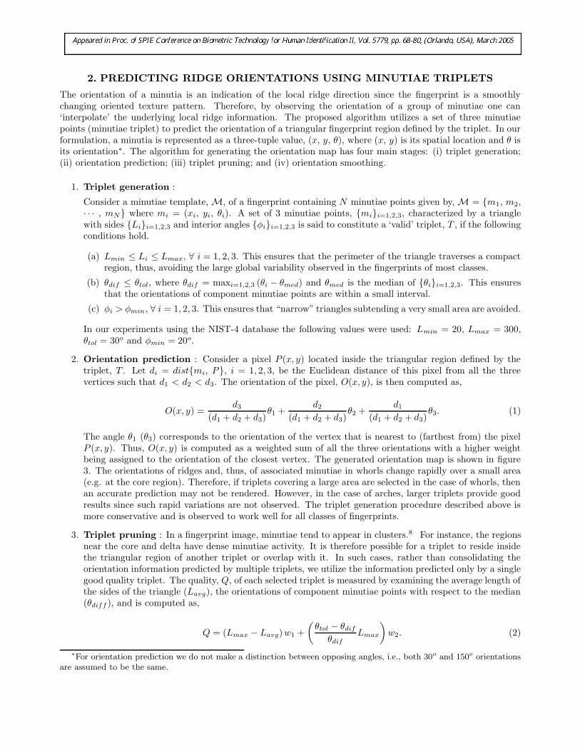
The orientation of a minutia is an indication of the local ridge direction since the fingerprint is a smoothlychanging oriented texture pattern. Therefore, by observing the orientation of a group of minutiae one can‘interpolate’ the underlying local ridge information. The proposed algorithm utilizes a set of three minutiaepoints (minutiae triplet) to predict the orientation of a triangular fingerprint region defined by the triplet. In ourformulation, a minutia is represented as a three-tuple value, (x, y, θ), where (x, y) is its spatial location and θ isits orientation∗. The algorithm for generating the orientation map has four main stages: (i) triplet generation;(ii) orientation prediction; (iii) triplet pruning; and (iv) orientation smoothing.
1. Triplet generation :
Consider a minutiae template, M, of a fingerprint containing N minutiae points given by, M = {m1, m2,· · · , mN} where mi = (xi, yi, θi). A set of 3 minutiae points, {mi}i=1,2,3, characterized by a trianglewith sides {Li}i=1,2,3 and interior angles {φi}i=1,2,3 is said to constitute a ‘valid’ triplet, T , if the followingconditions hold.
(a) Lmin ≤ Li ≤ Lmax, ∀ i = 1, 2, 3. This ensures that the perimeter of the triangle traverses a compactregion, thus, avoiding the large global variability observed in the fingerprints of most classes.
(b) θdif ≤ θtol, where θdif = maxi=1,2,3 (θi − θmed) and θmed is the median of {θi}i=1,2,3. This ensuresthat the orientations of component minutiae points are within a small interval.
(c) φi > φmin, ∀ i = 1, 2, 3. This ensures that “narrow” triangles subtending a very small area are avoided.
In our experiments using the NIST-4 database the following values were used: Lmin = 20, Lmax = 300,θtol = 30o and φmin = 20o.
2. Orientation prediction : Consider a pixel P (x, y) located inside the triangular region defined by thetriplet, T . Let di = dist{mi, P}, i = 1, 2, 3, be the Euclidean distance of this pixel from all the threevertices such that d1 < d2 < d3. The orientation of the pixel, O(x, y), is then computed as,
O(x, y) =d3
(d1 + d2 + d3)θ1 +
d2
(d1 + d2 + d3)θ2 +
d1
(d1 + d2 + d3)θ3. (1)
The angle θ1 (θ3) corresponds to the orientation of the vertex that is nearest to (farthest from) the pixelP (x, y). Thus, O(x, y) is computed as a weighted sum of all the three orientations with a higher weightbeing assigned to the orientation of the closest vertex. The generated orientation map is shown in figure3. The orientations of ridges and, thus, of associated minutiae in whorls change rapidly over a small area(e.g. at the core region). Therefore, if triplets covering a large area are selected in the case of whorls, thenan accurate prediction may not be rendered. However, in the case of arches, larger triplets provide goodresults since such rapid variations are not observed. The triplet generation procedure described above ismore conservative and is observed to work well for all classes of fingerprints.
3. Triplet pruning : In a fingerprint image, minutiae tend to appear in clusters.8 For instance, the regionsnear the core and delta have dense minutiae activity. It is therefore possible for a triplet to reside insidethe triangular region of another triplet or overlap with it. In such cases, rather than consolidating theorientation information predicted by multiple triplets, we utilize the information predicted only by a singlegood quality triplet. The quality, Q, of each selected triplet is measured by examining the average length ofthe sides of the triangle (Lavg), the orientations of component minutiae points with respect to the median(θdiff ), and is computed as,
Q = (Lmax − Lavg) w1 +
(
θtol − θdif
θdif
Lmax
)
w2. (2)
∗For orientation prediction we do not make a distinction between opposing angles, i.e., both 30o and 150o orientationsare assumed to be the same.

(a) (b) (c)
Figure 3. (a) Minutiae distribution of a fingerprint. (b) Examples of a good quality triplet (blue) with Lavg = 112.66,θdiff = 5, Q = 237.63 and a bad quality triplet (red) with Lavg = 217, θdiff = 26, Q = 67.55. (c) Estimated orientationmap.
Here, w1 and w2 are the weights associated with each term (w1 = 0.4 and w2 = 0.6, in our experiments).This ensures that a triplet having minutiae of similar orientations and traversing a relatively compact regionis assigned a higher Q value (Figure 3(b)). A good quality triangle will lead to a better estimation of theorientation of the underlying ridges according to our algorithm. We compute the orientation at discretepoints (every 13th pixel) in the fingerprint region. Hence, for a 512× 512 image, a 39× 39 orientation mapis generated.
4. Averaging the orientation map: To obtain a smooth transition in orientations, the predicted orientationmap is convolved with a 3 × 3 local averaging filter.
3. CLASSIFICATION OF FINGERPRINTS USING MINUTIAE FEATURES
Fingerprint classification refers to the problem of assigning a fingerprint to a pre-defined class in a consistentand reliable way. Usually fingerprint matching is performed using local features such as local ridge and minutiaedetails whereas fingerprint classification uses global features such as the ridge shape and singular points. Allexisting fingerprint classification schemes use the fingerprint image along with one or more features like ridgeline flow, location of singularities, or the orientation map to determine the fingerprint class. A detailed literaturereview of existing fingerprint classification techniques is described by Maio et al.9
In this paper, we use only the minutiae information for classification. Roxburgh10 observed a correlationbetween neighboring minutiae and variation in minutiae position with the pattern of the fingerprint. Such ob-servations reported in the forensic literature substantiate our hypothesis that the seemingly random distributionof minutiae in a fingerprint can reveal important information about the class of a fingerprint. The main steps ofour minutiae-based classification algorithm are summarized in the block diagram shown in Figure 4.
Minutiae triplet
formation
Predicting orientation
map
Detecting salient
minutiae
Forming feature vector
K-nearest neighbor classifier
Figure 4. The minutiae-based classification algorithm.
1. Detecting registration point using Hough Transform : A visual analysis of the fingerprint ridgepatterns of various classes indicates that they all have almost the same ridge structure in the base andmarginal areas11 as shown in Figure 5.

Marginal Area
Core Area
Base Area
(a) (b)
(c) (d)
Figure 5. (a) and (b) show the base, core and marginal area of two fingerprints representing the L and W classes. (c)and (d) are the corresponding original fingerprints.
But the irregularities in the vicinity of the core (such as a circular ridge pattern in the case of whorls orthe recurving of ridges in the case of loops) are significant from a classification standpoint. Therefore,the minutiae present in the vicinity of core point can reveal important class characteristics. In order toselect these ‘salient’ minutiae, we first detect a registration point (R0) using the Hough transform12 whichcan identify parametric shapes when sufficient evidence is available. In our case, this evidence consists ofminutiae coordinates and their orientations. We specifically observe that the ridges around the core pointexhibit high curvature forming a nearly circular pattern and, consequently, the orientations of minutiaeassociated with these ridges may aid in the detection of the registration point.
Note that all minutiae contributing to a potential circle will have orientations almost tangential to thecircumference. Figure 6(a) shows an ideal plot of minutiae residing on the circumferences of two concentriccircles. Since the minutiae orientation is perpendicular to the radius joining the minutiae and the centerpoint, each minutiae m can define a set of circles whose centers lie on the line L that is perpendicular to theorientation of m (Figure 6(b)). The radius r of each circle is the distance between m and the correspondingcenter. Thus, a 3D accumulator in Hough space denoted as (x, y, r) can be used for detecting R0 as describedbelow.
(a) Initialize the accumulator A(x, y, r) where (x, y) is the center of the potential circle with radius r.
(b) For each minutiae mi, i = 1 to N , the potential centers (x, y) lie on the line L. The accumulator cellA(x, y, r) is incremented if the point (x, y) is at a distance r from minutiae mi.
(c) For a circular minutiae pattern, there will be a well-pronounced peak in the Hough parameter spacecorresponding to one center (x, y). This is the registration point, R0, that is characterized by signifi-cant minutiae activity around it.
We use both the minutiae information and the predicted orientation map to detect the registration point.Since the ridge structure in fingerprints is not circular, we also consider lines that are nearly perpendicular(± 30o) to the orientation θ. The results of the Hough Transform using the predicted orientation maps ofvarious classes are shown in Figure 7. Note that in all cases R0 is detected in the vicinity of the true ‘core’or ‘center’ point.

(a) (b)
Figure 6. Using the Hough transform to detect the registration point. (a) An ideal minutiae distribution defining thecenter of a circle (‘∗’). (b) Line L is perpendicular to the orientation (θ) of minutiae m. Each point on L represents thecenter of a potential circle.
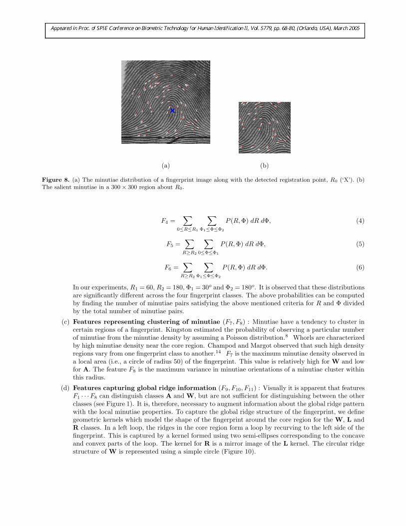
2. Selecting salient minutiae : As stated earlier, the minutiae in the vicinity of the core region have class-representative properties. Thus only the minutiae located in a 300× 300 region about R0 are used by theclassification algorithm (Figure 8).
3. Generating feature vectors : We next extract a set of 11 features from the minutiae distribution. Mostof these class-representative minutiae characteristics have been studied by various forensic experts such asGalton,6 Roxburgh10 and Kingston8 in the context of fingerprint individuality; however, these have notbeen used for classifying fingerprints. Our goal is to imitate the procedure adopted by a human fingerprintexpert instructed with the task of classifying fingerprints using minutiae information alone. Features suchas minutiae density and clusters of minutiae having homogeneous orientations are easily captured by thehuman eye but pose a significant challenge to machine vision systems.
The features we use are invariant to rotation and translation of the parent fingerprint image. The 11-dimensional vector F = {F1, F2, · · ·, F11} is constructed as follows.
(a) Features based on minutiae orientations (F1, F2) : The direction of ridge flow varies from oneclass to another and so does the minutiae orientation. For instance, the W class has at least one ridgewhich traces a 360 degree closed path in the central region of the fingerprint. Thus the orientationsof these minutiae range from 0 − 360 degrees. On the other hand, the minutiae orientations of Ahave only two dominant directions. In order to understand the distribution of minutiae orientationsfor each class, we examine the rose plots † of minutiae orientations (Figure 9). One feature capturingthese variations in minutiae orientations across classes is the number of empty bins in the rose plot(F1). This indirectly captures the spread of minutiae orientations. Also, F2 is defined to be thevariance in the orientations of the minutiae points.
(b) Features relating minutiae pairs (F3,· · ·,F6) : Minutiae pairs are fundamental units for represent-ing variations in fingerprints13 since the properties of neighboring minutiae vary with fingerprint class.For instance, the neighboring minutiae in the central region of W have large orientation differenceswhereas minutiae neighbors in class A have similar orientations. The correlation between spatial loca-tion and orientations of minutiae pairs can be examined by estimating the joint distribution P (R, Φ),where R is the distance between two minutiae and Φ is the difference in their orientation. Six differentfeatures (see Eqns. (3) - (6)) are extracted from this joint distribution. F3 represents minutiae pairsthat are spatially close to each other and have almost similar orientations, while F4 represents pairsthat are close but have a large orientation difference. F5 represents minutiae pairs that are far awayfrom each other and having similar orientations, and F6 represents minutiae pairs that are far awayfrom each other but having large orientation differences.
F3 =∑
0≤R≤R1
∑
0≤Φ≤Φ1
P (R, Φ) dR dΦ, (3)
†The rose plot is a a polar plot showing the histogram of angles.

(a) (b)
(c) (d)
(e) (f)
Figure 7. (a), (c), (e) show the minutiae distribution of three classes (A, L and W). The corresponding R0 points (’X’)detected using the estimated orientation maps are shown in (b), (d) and (f).
(a) (b)
Figure 8. (a) The minutiae distribution of a fingerprint image along with the detected registration point, R0 (‘X’). (b)The salient minutiae in a 300 × 300 region about R0.
F4 =∑
0≤R≤R1
∑
Φ1≤Φ≤Φ2
P (R, Φ) dR dΦ, (4)
F5 =∑
R≥R2
∑
0≤Φ≤Φ1
P (R, Φ) dR dΦ, (5)
F6 =∑
R≥R2
∑
Φ1≤Φ≤Φ2
P (R, Φ) dR dΦ. (6)
In our experiments, R1 = 60, R2 = 180, Φ1 = 30o and Φ2 = 180o. It is observed that these distributionsare significantly different across the four fingerprint classes. The above probabilities can be computedby finding the number of minutiae pairs satisfying the above mentioned criteria for R and Φ dividedby the total number of minutiae pairs.
(c) Features representing clustering of minutiae (F7, F8) : Minutiae have a tendency to cluster incertain regions of a fingerprint. Kingston estimated the probability of observing a particular numberof minutiae from the minutiae density by assuming a Poisson distribution.8 Whorls are characterizedby high minutiae density near the core region. Champod and Margot observed that such high densityregions vary from one fingerprint class to another.14 F7 is the maximum minutiae density observed ina local area (i.e., a circle of radius 50) of the fingerprint. This value is relatively high for W and lowfor A. The feature F8 is the maximum variance in minutiae orientations of a minutiae cluster withinthis radius.
(d) Features capturing global ridge information (F9, F10, F11) : Visually it is apparent that featuresF1 · · ·F8 can distinguish classes A and W, but are not sufficient for distinguishing between the otherclasses (see Figure 1). It is, therefore, necessary to augment information about the global ridge patternwith the local minutiae properties. To capture the global ridge structure of the fingerprint, we definegeometric kernels which model the shape of the fingerprint around the core region for the W, L andR classes. In a left loop, the ridges in the core region form a loop by recurving to the left side of thefingerprint. This is captured by a kernel formed using two semi-ellipses corresponding to the concaveand convex parts of the loop. The kernel for R is a mirror image of the L kernel. The circular ridgestructure of W is represented using a simple circle (Figure 10).

2
4
6
8
30
210
60
240
90
270
120
300
150
330
180 0
1
2
3
4
30
210
60
240
90
270
120
300
150
330
180 0
2
4
6
8
30
210
60
240
90
270
120
300
150
330
180 0
2
4
6
30
210
60
240
90
270
120
300
150
330
180 0
(a) (b) (c) (d)
Figure 9. Rose plots of (a) A, (b) W, (c) L, (d) R fingerprint classes.
Since arch-like characteristics are observed in the marginal area of all classes of fingerprints (Figure 5),we do not define a kernel for class A as it would erroneously fit all the other classes. The kernel fittingalgorithm that we have adopted is similar to the one proposed by Jain and Minut15 for fingerprintclassification and is based on the estimated orientation map. Consider V to be a smooth flow field(i.e., the orientation map) defined over some region in the plane R2 and let β be its orientation. Letγt = (x(t), y(t)) be the kernel curve in R2 as shown in Figure 11.
(a) (b) (c)
Figure 10. Kernels for the (a) W, (b) L and (c) R classes.
Figure 11. The kernel fitting process. The red line is the unit tangent vector to the kernel while the blue line indicatesthe direction of flow field at point γt.
15
Let γ̇ be the tangent to γ and let α be its orientation. To find how well each kernel fits the orientation

map of the fingerprint, an energy functional capturing the difference between the direction of γ̇ and thatof the vector field V at point γt is defined as follows:
E(γ) =
∫
γsin2(α − β(γ)) dγ
∫
γdγ
. (7)
The kernel-fitting process now becomes a simple energy minimization problem. For each predicted orien-tation map, we find three energy functional values (Eqn. 7) corresponding to the L, R, and W kernels.This results in features F9, F10 and F11, respectively. We observe that due to the inherent similarity inthe ridge structures of the 2 loops and A, both the L and R kernels fit well for A. Therefore, for class Athe values for F9 and F10 will be very similar. This property is useful in resolving the ambiguity betweenthe loops and class A. Note that the kernels are defined with respect to R0; for W, R0 is the center of thecircle whereas for L and R, it is the focus of the elliptical kernel.
The rotation and translation of fingerprints are taken into account by subjecting these kernels to varioustypes of transformations: the radius of the W kernel is varied in the interval [100, 160]; the semi-majoraxis of the L and R classes is varied in the interval [120, 180] while the semi-minor axis is varied in theinterval [60, 100]; the angle that the ellipse makes with the horizontal is varied in the range [−10o, 10o].Further, the kernels themselves are translated in a 20× 20 window around R0. Only the minimum of eachenergy functional over all possible kernel transformations is used to define the features F9, F10 and F11.
4. Classification of fingerprints : The 5 nearest neighbor classifier (5NN) using the Manhattan distancewas employed to classify the 11-dimensional feature. We conducted experiments using the NIST-4 databasethat contains 2000 pairs of fingerprint images (each of size 512× 512) corresponding to five classes. Minu-tiae information was extracted using the algorithm proposed by Hong et al.3 We combine the fingerprinttemplates from the A and T classes into one single class (A). Since we require a sufficient number ofminutiae triplets to estimate the orientation map, we reject those templates having fewer than 25 minutiaepoints; also, the templates of ambiguous fingerprints (those having multiple class labels) were not consid-ered. In order to ensure that we have the same number of samples per class, we eventually worked with700 fingerprints from each class - 150 fingerprint templates (randomly chosen) were used for training and550 templates were used for testing. We observe that by reducing the dimensionality of the feature vectorfrom 11 to 8 via an exhaustive feature selection process (features F5, F6 and F8 are eliminated) improvesclassification performance. The performance can be further improved by using the weighted manhattandistance where each feature is assigned a different weight based on its individual performance using the5NN classifier. A classification rate of 82% was obtained and the resultant confusion matrix is shown inTable 1.
True Assigned ClassClass A L R W
A 467 45 32 6L 61 464 7 18R 69 26 448 7W 4 61 68 417
Table 1. Confusion matrix indicating classification performance.
3.1. Analyzing classifier performance
Although our classification result is inferior to the present state-of-the-art fingerprint classification techniques,9
our intention is to show that it is feasible to estimate the class of a fingerprint using its minutiae template alone.Most of the misclassifications represents the cases where ridges contributing to important pattern characteristics(e.g., recurving ridges) do not have minutiae. For example, in Figure 12 it can be seen that the minutiae plotdoes not capture the recurving of ridges in the core region of a right loop thus resulting in a classification error.

Figure 12. The minutiae distribution of a R class fingerprint. The recurving ridge information is not captured by theminutiae.
4. FINGERPRINT RECONSTRUCTION
Very few studies on synthetic fingerprint generation have been reported in the literature. The software developedby Cappelli et al.16 called SFINGE uses Gabor-like space invariant filters to create fingerprint images. TheSFINGE algorithm uses an iterative procedure to generate ridge patterns from an initially empty image containinga few seeds. In this process, fingerprint minutiae of different types are automatically generated at randompositions.
In our reconstruction algorithm, we use the Gabor-like filter used by SFINGE. The filter, f , is the productof a cosine plane wave modulated by a Gaussian envelope, and takes the following form:
f(v) =1
σ2e−
||v||2
2σ2 [cos(k.v) − e−
σ||k||2
2 ]. (8)
Here, σ = 1.2 is the variance of the Gaussian envelope which decides the bandwidth of the filter, and k is thewave factor of the plane wave which is determined by the local (estimated) orientation. Let z be a point in theimage about which the filter has to be applied. Further, let O(z) denote the local estimated orientation. Thenk = [kx, ky] can be derived by solving the following two equations:
Dz =√
k2x + k2
y (9)
tan (O(z)) = −kx
ky
(10)
D(z) is related to the frequency of the filter and is set to 1/σ. Our algorithm for fingerprint reconstructionis as follows. We divide an (empty) fingerprint image of size 512 × 512 into non-overlapping blocks. We then
associate each block, X(0)z , with an orientation value, O(z), estimated using our algorithm. Note that certain
blocks may not have orientation information since the estimated orientation map can be incomplete. The block
X(0)z is next initialized with a noisy blob and is convolved with the filter, f , whose parameters are tuned using
O(z). This results in a new image X(1)z which is again subjected to the convolution procedure; this process
is repeated k times resulting in an image X(k)z which exhibits ridge-like patterns. Figure 13 shows the ridge
pattern generated over the entire fingerprint region (k = 25). Since a constant value of σ = 1.2 is used for allthe blocks, the inter-ridge spacing is observed to be the same throughout the image. This algorithm gives goodreconstruction results for all the fingerprint classes.

(a) (b) (c)
Figure 13. Reconstructing fingerprints. (a) Minutiae distribution of a fingerprint image. (b) Predicted orientation map(c) Reconstructed fingerprint.
5. SUMMARY AND FUTURE WORK
We have shown that the orientations of fingerprint ridges can be effectively predicted using minutiae points. Thiscan be beneficial in applications like smart cards (where memory is critical) since the orientation map requiredfor matching need not be stored explicitly but can be generated from the template. We have also demonstratedthat minutiae information alone may be used for classifying fingerprints. We are currently exploring the use ofa hierarchical classifier to perform classification.
Vendors of several minutiae-based fingerprint systems have denied the possibility that the stored templatescould be used to generate implicit fingerprint information.‡ Our preliminary results on reconstruction show thatminutiae templates are indeed vulnerable to the masquerade attack. The increasing use of biometric systemswith vulnerable templates demands the design of robust fingerprint templates (besides employing encryption,watermarking and shielding functions17). One potential approach would be to systematically exclude certainsalient minutiae from the template that are critical to image reconstruction without drastically affecting thematching performance. We are also looking at ways to reconstruct the fingerprint image with the minutiaeplaced at pre-determined locations. Finally, a way to exploit the predicted class information for reconstructionneeds to be explored.
6. ACKNOWLEDGEMENTS
This research was partially supported by NSF/ITR Grant # CNS-0325640.
‡All web-sites last accessed in January 2005:
1. http://www.biometricaccess.com/company/n 050798.htm: “You cannot reconstruct the original image from theminutiae...”
2. http://www.dodgeglobe.com/stories/111100/bus scans.shtml: “...template of minutiae points cannot be used tore-create the original fingerprint...”
3. http://www.sun.com/solutions/documents/white-papers/SNAP SolutionsGuide.pdf: “..it is not possible to recre-ate the fingerprint from the stored template..”
REFERENCES
1. A. Adler, “Can images be regenerated from biometric templates?,” in Biometrics Consortium Conference,(Arlington, VA), September 2003.
2. C. Hill, “Risk of masquerade arising from the storage of biometrics,” Master’s thesis, Australian NationalUniversity, 2001.
3. A. K. Jain, L. Hong, and R. Bolle, “On-line fingerprint verification,” IEEE Trans on Pattern Analysis
Machine Intelligence 19, pp. 302–314, April 1997.
4. E. Henry, Classification and Uses of fingerprints, Routledge, London, 1900.
5. S. Pankanti, S. Prabhakar, and A. K. Jain, “On the individuality of fingerprints,” IEEE Transactions on
Pattern Analysis and Machine Intelligence 24(8), pp. 1010–1025, 2002.
6. F. Galton, Finger Prints, McMillan, London, 1892.
7. U. Uludag and A. K. Jain, “Fingerprint minutiae attack system,” in Biometrics Consortium Conference,(Arlington, VA), September 2004.
8. C. Kingston, Probabilistic Analysis of Partial Fingerprint Patterns. PhD thesis, University of California,Berkeley, 1964.
9. D. Maltoni, D. Maio, A. K. Jain, and S. Prabhakar, Handbook of fingerprint recognition, Springer-Verlag,New York, Berlin Heidelberg, 1st ed., 2003.
10. T. Roxburgh, “On the evidential value of fingerprints,” Sankhya: Indian Journal of Statistics , pp. 189–214,1993.
11. C. V. K. Rao, Pattern Recognition Techniques Applied to Fingerprints. PhD thesis, Linkoeping, Sweden,1977.
12. D. H. Ballard, “Generalizing the hough transform to detect arbitrary shapes,” Pattern recognition 13(3),pp. 111–112, 1997.
13. D. A. Stoney, Quantitative Assessment of Fingerprint Individuality. PhD thesis, University of California,Davis, 1985.
14. C. Champod and P. Margot, “Computer assisted analysis of minutiae occurrences on fingerprints,” in Proc.
Int’l Symp. Fingerprint Detection and Identification, p. 305, 1996.
15. A. K. Jain and S. Minut, “Hierarchical kernel fitting for fingerprint classification and alignment,” in Proc.
of International Conference on Pattern Recognition, 2, pp. 469–473, August 2002.
16. R. Cappelli, D. Maio, and D. Maltoni, “Synthetic fingerprint image generation,” in Proc. of 15th Int. Conf.
on Advances in Pattern Recognition, 3(5), pp. 475–478, 2000.
17. J.-P. Linnartz and P. Tuyls, “New shielding functions to enhance privacy and prevent misuse of biometrictemplates,” in Proc. of Audio- and Video-based Person Authentication, pp. 393–402, (Guildford, UK), June2003.