towards urban 3d reconstruction from videomarc/pubs/akbarzadeh3dpvt06.pdfprocessing pipeline for...
TRANSCRIPT

Towards Urban 3D Reconstruction From Video
A. Akbarzadeh∗, J.-M. Frahm+, P. Mordohai+, B. Clipp+, C. Engels∗, D. Gallup+,P. Merrell+, M. Phelps∗, S. Sinha+, B. Talton+, L. Wang∗, Q. Yang∗, H. Stewenius∗,
R. Yang∗, G. Welch+, H. Towles+, D. Nister∗ and M. Pollefeys+
∗Department of Computer Science +Department of Computer ScienceCenter for Visualization and Virtual Environments University of North Carolina at Chapel Hill
University of Kentucky, Lexington, USA Chapel Hill, USA
Abstract
The paper introduces a data collection system and aprocessing pipeline for automatic geo-registered 3D recon-struction of urban scenes from video. The system collectsmultiple video streams, as well as GPS and INS measure-ments in order to place the reconstructed models in geo-registered coordinates. Besides high quality in terms ofboth geometry and appearance, we aim at real-time per-formance. Even though our processing pipeline is currentlyfar from being real-time, we select techniques and we de-sign processing modules that can achieve fast performanceon multiple CPUs and GPUs aiming at real-time perfor-mance in the near future. We present the main considera-tions in designing the system and the steps of the processingpipeline. We show results on real video sequences capturedby our system.
1 Introduction
Detailed, 3D models of cities are usually made fromaerial data, in the form of range or passive images com-bined with other modalities, such as measurements froma Global Positioning System (GPS). While these modelsmay be useful for navigation, they provide little additionalinformation compared to maps in terms of visualization.Buildings and other landmarks cannot be easily recognizedsince the facades are poorly reconstructed from aerial im-ages due to bad viewing angles. To achieve high-qualityground-level visualization one needs to capture data fromthe ground. A system that automatically generates texture-mapped, ground-level 3D models should be capable ofcapturing large amounts of data while driving through thestreets and of processing these data efficiently.
In this paper, we introduce an approach for fully auto-matic 3D reconstruction of urban scenes from several hoursof video data captured by a multi-camera system. The goal
is an automatic system for processing very large amountsof video data acquired in an unconstrained manner. Thisforces us to take shape from video out of the laboratory andto achieve a fieldable system.
The video acquisition system consists of eight camerasmounted on a vehicle, with a quadruple of cameras lookingto each side. The cameras have a resolution of 1024 × 768pixels and a frame rate of 30 Hz. Each quadruple consistsof cameras directed straight sideways (orthogonal to thedriving direction), and diagonally forward, backward andupwards with minimal overlap to achieve a large horizon-tal and vertical field of view. Additionally, the acquisitionsystem employs an Inertial Navigation System (INS) and aGPS to enable geo-registration of the cameras. Examples ofground-level reconstructions from our system can be seen inFigs. 1 and 2.
Figure 1. Example of dense reconstruction.
The entire acquisition system is packaged in a sealedpod, which is mounted on the back of a vehicle. As thevehicle is driven through urban environments, the captured
1

Figure 2. Dense reconstruction of a cityblock.
video is stored on disk drives in the pod. After a capturesession, the drives are moved from the pod on the vehicleto a 10-PC (dual-processor) computer cluster for process-ing. Our performance goal is to process up to 6 hours ofacquired data in an equal amount of time.
Processing entails the following steps: sparse recon-struction during which the geo-registered poses of the cam-eras are estimated from the video and the INS/GPS data;and dense reconstruction during which a texture-mapped,3D model of the urban scene is computed from the videodata and the results of the sparse step.
In sparse reconstruction the trajectory of the camera isestimated from the video data using structure from motiontechniques. The goal is to achieve precise camera poses inorder to support temporal multi-view stereo, while keepinga globally coherent geo-registered trajectory free of drift.To this end, the INS/GPS data are post-processed to ob-tain a filtered precise trajectory of the vehicle, which iscalled Smoothed Best Estimated Trajectory (SBET). TheSBET and the hand-eye calibration between the origin ofthe SBET coordinate system and the coordinate systems ofthe cameras provide reliable estimates of the camera trajec-tories.
In dense reconstruction, the surfaces of the buildings,ground and other structures are estimated using multi-viewstereo techniques. The goal of this step is to provide accu-rate surfaces wherever possible even in the presence of am-biguous or little surface texture, occlusion or specularity.The reconstruction step is divided into multi-view stereo,which produces depth-maps from multiple views with a sin-
gle reference view, and depth-map fusion, which resolvesconflicts between multiple depth maps and derives a coher-ent surface description. The dense reconstruction stage alsoprovides texture for the surfaces using the video input.
The remainder of the paper is organized as follows. Sec-tion 1.1 discusses related work. The processing pipeline isdescribed in detail in Section 2, while the different systemaspects of a multi-camera capture system with INS/GPSrecording are outlined in Section 3. Experimental resultsare reviewed in Section 4 with conclusions in Section 5.
1.1 Previous Work
The research community has devoted a lot of effort to themodeling of man-made environments using a combinationof sensors and modalities. Here, we briefly review work re-lying on ground-based imaging since it is more closely re-lated to our project. An equal, if not larger, volume of workexists for aerial imaging. The typical goal is the accurate re-construction of urban or archaeological sites, including bothgeometry and texture, in order to obtain models useful forvisualization, quantitative analysis in the form of measure-ments at large or small scales and potentially for studyingtheir evolution through time.
A natural choice to satisfy the requirement of modelingthe geometry and appearance is the combined use of activerange scanners and digital cameras. Stamos and Allen [1]used such a combination, while also addressing the prob-lems of registering the two modalities, segmenting the dataand fitting planes to the point cloud. El-Hakim et al. [2]propose a methodology for selecting the most appropriatemodality among range scanners, ground and aerial imagesand CAD models. Fruh and Zakhor [3] developed a sys-tem that is very similar to ours since it is also mounted ona vehicle and captures large amounts of data in continuousmode, in contrast to the previous approaches that captureda few, isolated images of the scene. Their system consistsof two laser scanners, one for map construction and regis-tration and one for geometry reconstruction, and a digitalcamera, for texture acquisition. A system with similar con-figuration, but smaller size, that also operates in continuousmode was presented by Biber et al. [4]. Other work onlarge scale urban modeling includes the 4D Atlanta projectcarried out by Schindler et al. [5], which also examines theevolution of the model through time. Cornelis et al. [6] havealso developed a system specialized for the reconstructionof facades from a stereo rig mounted on a moving vehicle.
Laser scanners have the advantage of providing accurate3D measurements directly. On the other hand, they can becumbersome and expensive. Several researchers in pho-togrammetry and computer vision address the problem ofreconstruction relying solely on passive sensors (cameras)in order to increase the flexibility of the system while de-
2

creasing its size, weight and cost. The challenges are duemostly to the well-document inaccuracies in 3D reconstruc-tion from 2D measurements. To obtain useful models onemay have to interact with the system or make simplifyingassumptions. Among the first such attempts was the MITCity Scanning project, an overview of which can be foundin [7]. A semi-automatic approach under which simple geo-metric primitives are fitted to the data was proposed by De-bevec et al. [8]. Compelling models can be reconstructedeven though fine details are not modeled but treated as tex-ture instead. Rother and Carlsson [9] show that multiple-view reconstruction can be formulated as a linear estima-tion problem given a known fixed plane that is visible inall images. This approach also requires manual operations.Dick et al. [10] presented an automatic approach that inferspiecewise planar surfaces from sparse features taking intoaccount constraints such as orthogonality and verticality.The authors later proposed a more elaborate, MCMC-basedmethod [11] that uses generative models for buildings. Itis also fully automatic, but is restricted by the prior mod-els and can only operate on small sets of images, typicallytwo to six. Similar high-level reasoning is also employedby [5]. Werner and Zisserman [12] presented an automaticmethod, inspired by [8], that fits planes and polyhedra onsparse reconstructed primitives by examining the supportthey receive via a modified version of the space sweep al-gorithm [13].
We approach the problem using passive sensors only,building upon the experience from intensive study of struc-ture from motion and shape reconstruction within the com-puter vision community in the last two decades. Since thisliterature is too large to survey here, the interested readeris referred to [14, 15]. The emphasis in our project is ondeveloping a fully automatic system that is able to operatein continuous mode without the luxury of capturing datafrom selected viewpoints since capturing is performed froma moving vehicle constrained to the vantage points of ur-ban streets. Our system design is also driven by the per-formance goal of being able to post-process the large videodatasets in a time equal to the acquisition time. Our as-sembled team has significant experience in most if not allaspects of structure from motion and stereo processing in-volved in producing textured, 3D models from images andvideo [16, 17, 18, 19, 20, 21].
2 Processing Pipeline
In the following we describe the different techniquesused in our system in more detail. The processing pipelinebegins by estimating a geo-registered camera pose for eachframe of the videos. We approach this by determining2D-2D point correspondences in consecutive video frames.Then, we use the relative camera geometry of the internally
calibrated cameras to establish a Euclidean space for thecameras. The INS/GPS information is used to compute thecamera position in the geo-spatial coordinate system.
Once the camera poses have been computed, we usethem together with the video frames to perform stereomatching on the input images. This leads to a depth mapfor each frame. These depth maps are later fused to enforceconsistency between them. A flow chart of the processingpipeline is shown in Fig. 3.
Figure 3. 3D processing pipeline
2.1 2D Feature Tracking
To establish 2D feature correspondences between con-secutive video frames we track features with a hierarchi-cal KLT tracker [22]. To achieve real-time tracking withvideo frame rate we use an implementation of the hierarchi-cal KLT tracker on the GPU [23]. It needs on average 30msto track 1000 feature points in a 1024 × 768 image on anATI X1900 graphics card.
The weakness of tracking techniques are large dispar-ity ranges as the flow-assumption of motion of less than apixel at the corresponding pyramid level limits the amountof motion that can be captured. Thus video frames withlarge disparities pose problems to the KLT tracker. Hence,we can also use a detect and match tracker similar to[24]. Its strength is that it can search large disparity rangesvery quickly – faster than video can be fetched from disk.Its weakness is that in noisy, low-texture conditions therepeatability of detection is not always reliable (a phe-nomenon similarly noted by [25]).
3

2.2 3D Camera Tracking
We are investigating and developing several approachesto determine the camera pose from the 2D feature tracks,depending on the availability of INS/GPS data. We wouldlike our system to be functional in the absence of such data.
When INS/GPS data are not available, we use a vision-only camera tracking algorithm along the lines of [18].Briefly stated, we can initialize the camera tracker with therelative pose of three views, given feature correspondencesin them. These correspondences are triangulated using thecomputed camera poses. Additional poses are computedwith RANSAC and hypothesis-generation using constraintsfrom 2D feature to 3D world point correspondences. Newworld points are re-triangulated using new views as they be-come available.
To avoid accumulated drift the system is periodically re-initialized with a new set of three views. We stitch the newposes into the old coordinate system exploiting the con-straints of one overlapping camera. The remaining degreeof freedom is the scale of the old and the new coordinatesystem. It is estimated using corresponding triangulatedpoints in both coordinate frames.
All pose estimation methods use preemptive RANSACand local iterative refinement for robustness [26]. In prac-tice, the system must re-initialize frequently unless we usebundle adjustment to refine poses. With bundle adjustmentthe pose estimation is less sensitive to measurement noisewhich leads to fewer re-initializations.
2.3 Geo-Registration with INS/GPS Data
To determine geo-registered coordinates of the featuresin the 3D model, we employ the INS/GPS data. TheINS/GPS measurement system is outfitted with a GPS re-ceiver, gyroscopes, and accelerometers. It delivers highlyaccurate measurements of the position and orientation ofthe vehicle on which the cameras are mounted.
A Euclidean transformation, which will be referred toas the hand-eye calibration, maps the center of the geo-location system to the optical center of each of the cameras.Initially each camera keeps its own coordinate frame. Theoptical center of the first frame of each camera is the originand the optical axis and the axes of the first image plane areused as the axes. The scale is arbitrarily chosen by settingthe distance between the first and second camera positionsin the video sequence to unit length.
Our first implementation of geo-registration computesa similarity transformation (rotation, translation and scale)between the poses of a given camera in the vision coordi-nate system and the poses of each camera in the world. Thisapproach has difficulties in dealing with drift in the vision-based camera pose estimation since it is limited to one rigid
transformation for all frames.We are currently developing a second approach which
overcomes these limitations by fusing geo-location mea-surements and tracked 2D features either using a Kalmanfilter or through bundle adjustment. These methods areexpected to outperform the similarity transformation, geo-registration technique.
2.4 Multi-View Stereo
The multi-view stereo module takes as input the cameraposes and images from a single video stream and producesa depth map for each frame. It uses the plane-sweep al-gorithm of Collins [13], which is an efficient multi-imagematching technique. Conceptually, a plane is swept throughspace in steps along a predefined direction, typically paral-lel to the optical axis. At each position of the plane, allviews are projected on it. If a point on the plane is at thecorrect depth, then, according to the brightness constancyassumption, all pixels that project on it should have consis-tent intensities. We measure this consistency by summingthe absolute intensity differences in square aggregation win-dows defined in the reference image, for which the depthmap is computed. The hypothesis with the minimum cost(sum of absolute differences) is selected as the depth esti-mate for each pixel.
(a) (b)Figure 4. Stereo depth maps rendered as 3Dmodels. (a) Fronto-parallel sweep only. (b)Multiple sweeping directions.
Traditional plane-sweeping techniques typically sweepfronto-parallel planes only, which do not account for per-spective observed in non-fronto-parallel surfaces. We ex-tend the algorithm by sweeping planes in multiple direc-tions, where the directions are aligned with the planar sur-faces we expect to observe in the scene such as the groundand building facades. We can deduce the orientations of theground and facade planes beforehand by assuming the vehi-cle drives parallel to the ground and to the facades, and thatthe facades are vertical and meet at right angles. Figure 4 il-lustrates the improvements gained by sweeping in multipledirections. Besides its ability to process multiple images atthe same time, the plane-sweep stereo algorithm can easily
4

be ported to the GPU to achieve very fast performance [27].
2.5 Stereo Fusion
Multi-view stereo provides a depth map for every refer-ence frame. Since we do not enforce consistency betweendepth maps during stereo, we need to enforce it in a sepa-rate stereo fusion step. Fusion serves two purposes: it im-proves the quality of the depth estimates by ensuring that es-timates for the same point are consistent with multiple depthmaps and it produces more economical representations bymerging multiple depth estimates into one. Related workincludes volumetric [28, 29], patch-based [30], viewpoint-based [31] and pixel-based [32] approaches. We opt for aviewpoint-based approach inspired by the median fusion al-gorithm [17]. A volumetric method is impractical since itwould require a very large number of voxels for our imageresolution and accuracy requirements. Instead we operateon the set of depth hypotheses for each pixel of the refer-ence view. It is useful to have the image plane as a refer-ence, because then the final mesh can be generated rapidlyby triangulating the depth estimates of adjacent pixels.
Given depth maps from a set of consecutive frames,the stereo fusion step resolves conflicts between computeddepths and produces a depth map in which most of the noisehas been removed. Fusion is highly effective because pointsare visible in large numbers of frames, which provide multi-ple depth estimates for each point. Even though each depthestimate is produced by a simple, fast stereo algorithm, theconsensus among these estimates is usually very accurate.Fusion is designed to resolve conflicts like those illustratedin Figure 5. In Figure 5.a, the depth estimate X in the viewof the reference camera Cref occludes the depth map di ofcamera Ci, while in Figure 5.b, the depth estimate X of thereference camera passes the depth map of camera Pi. Bothsituations are impossible and should be corrected.
One approach is the median fusion algorithm of [17].The input is a set of depth maps, one of which, typically theone in the middle, is used as reference. The algorithm aimsat selecting the best depth estimate for each pixel basedon their stability, which depends on the number and typeof conflicts between each depth hypothesis and other depthmaps. For each depth estimate of the reference depth map,the number of other depths maps that it occludes (Figure5.a) or passes (Figure 5.b) is computed. This process is re-peated for each depth estimate of all other depth maps withrespect to reference depth map. The selected (most stable)solution is defined as the minimum depth for which thereare at least as many depth maps that occlude it as there arethat pass it.
We are also working on a similar approach that takesinto account the confidence of each depth estimate. Stereoproduces more accurate depth estimates in parts of the im-
(a) X occludes di (b) X passes di
Figure 5. Illustration of conflicts betweendepth maps that have to be resolved by fu-sion
age where there is more texture and no occlusion. Thepresence of unambiguous matches is indicated by a sin-gle strong minimum of the cost computed during the plane-sweep stage. On the other hand, the cost functions of am-biguous matches have multiple minima. Based upon theform of the cost function, we can assign a confidence valueto each depth estimate. During fusion this confidence isincreased or decreased depending on whether other depthestimates support or contradict it. Depth estimates withvery low confidence are replaced with ones that agree moreclosely with their more confident neighbors. This approachintroduces a bias towards smooth surfaces, which may bejustified since our emphasis is on reconstructing buildings,and it is very effective in areas where the majority of depthestimates are wrong, such as uniform walls and streets. Onthe other hand, smoothness comes at the expense of fine de-tails, and the computation of confidence requires additionalprocessing cycles. Our future work in stereo fusion will fo-cus on a faster implementation of our algorithms and bettermethods for resolving occlusions using multiple views.
From the fused stereo depth maps, we generate a tri-angulated, texture-mapped, 3D model of the scene in geo-registered coordinates.
3 Video Acquisition System
The on-vehicle video acquisition system consists of twomain sub-systems - an 8-camera digital video recorder(DVR) and an Applanix INS/GPS (model POS LV) navi-gation system. The DVR streams the raw images to disk,and the Applanix system tracks position and orientation sothe 3D models produced in post-processing can be createdin a common geo-registered coordinate system.
The DVR is built with eight Point Grey Research (PGR)Flea color cameras, with one quadruple of cameras for eachside of the vehicle as shown in Figure 6. Each camera has
5
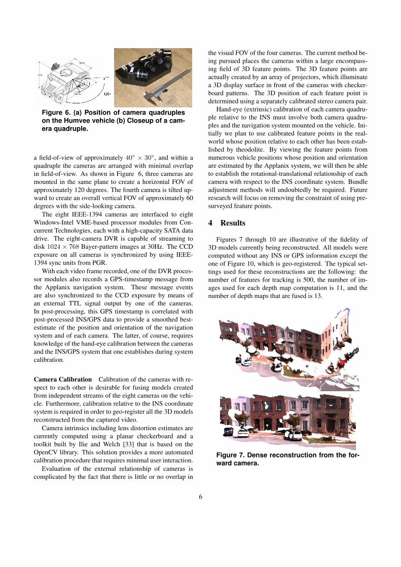
Figure 6. (a) Position of camera quadrupleson the Humvee vehicle (b) Closeup of a cam-era quadruple.
a field-of-view of approximately 40◦ × 30◦, and within aquadruple the cameras are arranged with minimal overlapin field-of-view. As shown in Figure 6, three cameras aremounted in the same plane to create a horizontal FOV ofapproximately 120 degrees. The fourth camera is tilted up-ward to create an overall vertical FOV of approximately 60degrees with the side-looking camera.
The eight IEEE-1394 cameras are interfaced to eightWindows-Intel VME-based processor modules from Con-current Technologies, each with a high-capacity SATA datadrive. The eight-camera DVR is capable of streaming todisk 1024 × 768 Bayer-pattern images at 30Hz. The CCDexposure on all cameras is synchronized by using IEEE-1394 sync units from PGR.
With each video frame recorded, one of the DVR proces-sor modules also records a GPS-timestamp message fromthe Applanix navigation system. These message eventsare also synchronized to the CCD exposure by means ofan external TTL signal output by one of the cameras.In post-processing, this GPS timestamp is correlated withpost-processed INS/GPS data to provide a smoothed best-estimate of the position and orientation of the navigationsystem and of each camera. The latter, of course, requiresknowledge of the hand-eye calibration between the camerasand the INS/GPS system that one establishes during systemcalibration.
Camera Calibration Calibration of the cameras with re-spect to each other is desirable for fusing models createdfrom independent streams of the eight cameras on the vehi-cle. Furthermore, calibration relative to the INS coordinatesystem is required in order to geo-register all the 3D modelsreconstructed from the captured video.
Camera intrinsics including lens distortion estimates arecurrently computed using a planar checkerboard and atoolkit built by Ilie and Welch [33] that is based on theOpenCV library. This solution provides a more automatedcalibration procedure that requires minimal user interaction.
Evaluation of the external relationship of cameras iscomplicated by the fact that there is little or no overlap in
the visual FOV of the four cameras. The current method be-ing pursued places the cameras within a large encompass-ing field of 3D feature points. The 3D feature points areactually created by an array of projectors, which illuminatea 3D display surface in front of the cameras with checker-board patterns. The 3D position of each feature point isdetermined using a separately calibrated stereo camera pair.
Hand-eye (extrinsic) calibration of each camera quadru-ple relative to the INS must involve both camera quadru-ples and the navigation system mounted on the vehicle. Ini-tially we plan to use calibrated feature points in the real-world whose position relative to each other has been estab-lished by theodolite. By viewing the feature points fromnumerous vehicle positions whose position and orientationare estimated by the Applanix system, we will then be ableto establish the rotational-translational relationship of eachcamera with respect to the INS coordinate system. Bundleadjustment methods will undoubtedly be required. Futureresearch will focus on removing the constraint of using pre-surveyed feature points.
4 Results
Figures 7 through 10 are illustrative of the fidelity of3D models currently being reconstructed. All models werecomputed without any INS or GPS information except theone of Figure 10, which is geo-registered. The typical set-tings used for these reconstructions are the following: thenumber of features for tracking is 500, the number of im-ages used for each depth map computation is 11, and thenumber of depth maps that are fused is 13.
Figure 7. Dense reconstruction from the for-ward camera.
6

Figure 8. Dense reconstruction from the sidecamera.
Figure 9. Dense reconstruction from the sidecamera.
Figure 10. Geo-registered dense reconstruc-tion from the side camera.
5 Summary and Conclusions
We have described a system aimed at real-time, dense,geo-registered, 3D urban reconstruction from video cap-tured by a multi-camera system and INS/GPS measure-ments. The quality of the initial reconstructed results bothwith and without INS/GPS sensors is very promising. Fu-ture challenges include improving the accuracy of geo-registration, improving the process of bundle adjustment orKalman filtering of the camera trajectory, registering andfusing the reconstructions across multiple video streams,speeding up the processing by porting operations to theGPU, and enhancing the processing pipeline to make itmore robust. Potential longer term directions are changedetection and the capability to perform incremental modelupdates using video acquired on different days.
Acknowledgement This work is partially supported byDARPA under the UrbanScape project, which is lead by theGeo-Spatial Technologies Information Division of SAIC.
References
[1] I. Stamos and P.K. Allen, “Geometry and texture re-covery of scenes of large scale,” Computer Visionand Image Understanding, vol. 88, no. 2, pp. 94–118,2002.
[2] S.F. El-Hakim, J.-A. Beraldin, M. Picard, and A. Vet-tore, “Effective 3d modeling of heritage sites,” in 4thInternational Conference of 3D Imaging and Model-ing, 2003, pp. 302–309.
[3] C. Fruh and A. Zakhor, “An automated method forlarge-scale, ground-based city model acquisition,” Int.J. of Computer Vision, vol. 60, no. 1, pp. 5–24, 2004.
[4] P. Biber, S. Fleck, D. Staneker, M. Wand, andW. Strasser, “First experiences with a mobile platformfor flexible 3d model acquisition in indoor and out-door environments – the waegele,” in Proceedings ofthe ISPRS Working Group V/4 Workshop: 3D-ARCH2005, 2005.
[5] G. Schindler, P. Krishnamurthy, and F. Dellaert,“Line-based structure from motion for urban environ-ments,” in 3DPVT, 2006.
[6] N. Cornelis, K. Cornelis, and L. Van Gool, “Fast com-pact city modeling for navigation pre-visualization,”in Int. Conf. on Computer Vision and Pattern Recog-nition, 2006.
[7] S. Teller, “Automated urban model acquisition:Project rationale and status,” in Image UnderstandingWorkshop, 1998, pp. 455–462.
7

[8] P. Debevec, C.J. Taylor, and J. Malik, “Modelingand rendering architecture from photographs: A hy-brid geometry- and image-based approach,” in SIG-GRAPH, 1996, pp. 11–20.
[9] C. Rother and S. Carlsson, “Linear multi view re-construction and camera recovery using a referenceplane,” Int. J. of Computer Vision, vol. 49, no. 2-3,pp. 117–141, 2002.
[10] A.R. Dick, P.H.S. Torr, and R. Cipolla, “Automatic 3dmodelling of architecture,” in British Machine VisionConference, 2000, pp. 273–289.
[11] A.R. Dick, P.H.S. Torr, and R. Cipolla, “Modellingand interpretation of architecture from several im-ages,” Int. J. of Computer Vision, vol. 60, no. 2, pp.111–134, 2004.
[12] T. Werner and A. Zisserman, “New techniquesfor automated architectural reconstruction from pho-tographs,” in European Conf. on Computer Vision,2002, pp. II: 541–555.
[13] R.T. Collins, “A space-sweep approach to true multi-image matching,” in Int. Conf. on Computer Visionand Pattern Recognition, 1996, pp. 358–363.
[14] R. Hartley and A. Zisserman, Multiple View Geome-try in Computer Vision, Cambridge University Press,2000.
[15] O.D. Faugeras, Three-Dimensional Computer Vision:A Geometric Viewpoint, MIT Press, 1993.
[16] M. Pollefeys, R. Koch, and L. Van Gool, “Self-calibration and metric reconstruction inspite of vary-ing and unknown intrinsic camera parameters,” Int. J.of Computer Vision, vol. 32, no. 1, pp. 7–25, 1999.
[17] D. Nister, Automatic dense reconstruction from uncal-ibrated video sequences, PhD Thesis, Royal Instituteof Technology KTH, Stockholm, Sweden, 2001.
[18] D. Nister, “An efficient solution to the five-point rela-tive pose problem,” IEEE Trans. on Pattern Analysisand Machine Intelligence, vol. 26, no. 6, pp. 756–777,2004.
[19] D. Nister, “Automatic passive recovery of 3d fromimages and video,” in 3DPVT, 2004, pp. 438–445.
[20] M. Pollefeys, L. Van Gool, M. Vergauwen, F. Verbiest,K. Cornelis, J. Tops, and R. Koch, “Visual modelingwith a hand-held camera,” Int. J. of Computer Vision,vol. 59, no. 3, pp. 207–232, 2004.
[21] M. Pollefeys, L. Van Gool, M. Vergauwen, K. Cor-nelis, F. Verbiest, and J. Tops, “Image-based 3drecording for archaeological field work,” ComputerGraphics and Applications, vol. 23, no. 3, pp. 20–27,2003.
[22] B.D. Lucas and T. Kanade, “An Iterative Image Reg-istration Technique with an Application to Stereo Vi-sion,” in Int. Joint Conf. on Artificial Intelligence,1981.
[23] S. Sinha, J.-M. Frahm, and M. Pollefeys, “GPU-basedVideo Feature Tracking and Matching,” Tech. Rep.TR06-012, University of North Carolina at ChapelHill, May 2006.
[24] D. Nister, O. Naroditsky, and J. Bergen, “Visualodometry for ground vehicle applications,” Journalof Field Robotics, vol. 23, no. 1, 2006.
[25] D. Lowe, “Distinctive image features from scale-invariant keypoints,” Int. J. of Computer Vision, vol.60, no. 2, pp. 91–110, 2004.
[26] D. Nister, “Preemptive RANSAC for live structureand motion estimation,” in Int. Conf. on ComputerVision, 2003, vol. 1, pp. 199–206.
[27] R. Yang and M. Pollefeys, “Multi-resolution real-timestereo on commodity graphics hardware,” in Int. Conf.on Computer Vision and Pattern Recognition, 2003,pp. I: 211–217.
[28] B. Curless and M. Levoy, “A volumetric method forbuilding complex models from range images,” SIG-GRAPH, vol. 30, pp. 303–312, 1996.
[29] M.D. Wheeler, Y. Sato, and K. Ikeuchi, “Consensussurfaces for modeling 3d objects from multiple rangeimages,” in Int. Conf. on Computer Vision, 1998, pp.917–924.
[30] P.V. Fua, “From multiple stereo views to multiple 3-dsurfaces,” Int. J. of Computer Vision, vol. 24, no. 1,pp. 19–35, 1997.
[31] P.J. Narayanan, P.W. Rander, and T. Kanade, “Con-structing virtual worlds using dense stereo,” in Int.Conf. on Computer Vision, 1998, pp. 3–10.
[32] R. Koch, M. Pollefeys, and L. Van Gool, “Multi view-point stereo from uncalibrated video sequences,” inEuropean Conf. on Computer Vision, 1998, pp. I: 55–71.
[33] A. Ilie and G. Welch, “Ensuring Color Consistencyacross Multiple Cameras,” in ICCV, 2005, pp. 1268–1275.
8