toyoko orimoto, caltech 1 cms electromagnetic calorimeter us cms jterm iii 12 january 2009 toyoko...
TRANSCRIPT

Toyoko Orimoto, Caltech 1
CMS Electromagnetic Calorimeter
US CMS JTERM III
12 January 2009
Toyoko Orimoto
California Institute of Technology
Toyoko Orimoto, Caltech 2
Outline
• Physics & Design Requirements
• Technology Choice
• ECAL Design & Readout
• Calibration & Monitoring
• Results with Cosmics Data
• Results with First Beam Data
• Conclusions

Toyoko Orimoto, Caltech 3
Physics Requirements: Discovery Potential
A light Higgs has not yet been excluded by current measurements, and we may be able to measure it at the LHC.
CMS NOTE 2003/033
H
Current limit from electroweak measurements is mH > 114 GeV.
At mass ~120 GeV, the Higgs decay into the diphoton channel presents a very promising yet challenging possibility.

Toyoko Orimoto, Caltech 4
Physics Requirements: Light HiggsIf such a low mass Higgs does exist, its natural width will very narrow.
For narrow resonances, the observed width will be determined by the instrumental mass resolution; that is, we will need the best possible calorimeter resolution to observe the Higgs in the diphoton channel.
Low Mass : Width at 100 GeV is < 0.01 GeV
High Mass : Width >10% of the mass
HMC Studies
Toyoko Orimoto, Caltech 5
Detector Energy Resolution
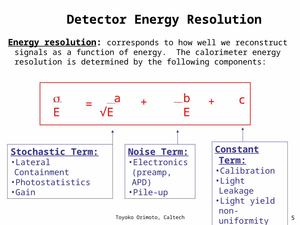
Energy resolution: corresponds to how well we reconstruct signals as a function of energy. The calorimeter energy resolution is determined by the following components:
Stochastic Term:•Lateral Containment•Photostatistics•Gain
Constant Term:•Calibration •Light Leakage•Light yield non-uniformity
•Temperature
Noise Term:•Electronics (preamp, APD)
•Pile-up
c b E
a√E
E
= + +

Toyoko Orimoto, Caltech 6
The LHC Environment
The Large Hadron Collider• 14 TeV proton proton collider• Design Luminosity = 1034 cm-2 s-1
• Bunch crossing (BX) rate 40 MHz(one BX every 25ns)
• Up to 20 p-p interactions and up to 1000 charged particles every BX
• Dose rates of 15 rad/h in Barrel & up to 1500 rad/h in Endcap
Detectors need to be:• Fast • High granular• Radiation resistant
QuickTime™ and aTIFF (Uncompressed) decompressor
are needed to see this picture.

Toyoko Orimoto, Caltech 7
ECAL Design Requirements
Compact: • To fit inside the magnet
Hermetic: • To measure missing ET
• Good resolution up to ||<2.5 • Coverage up to ||<3
Energy range: • ~0.1 – 1000 GeV
Fast: • Pile-up • Precise timing of signal
Excellent energy, angular resolution:
• As motivated by physics studies
Stable: • Accurate monitoring system• Several different calibration
procedures
Radiation resistant:• More than 10 years of operation
Segmented:• Projective• Reduce pile-up effects
Triggering ability:• Appropriate on-off detector
electronics
Non magnetic:• Operable in a 4T field

Toyoko Orimoto, Caltech 8
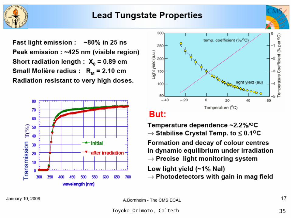
Scintillating Crystal Calorimeter: Lead-Tungstate (PbWO4 )
ECAL Technology Choice
QuickTime™ and aTIFF (Uncompressed) decompressor
are needed to see this picture.
Ideal calorimeter qualities:• Total absorption calorimeter• Short radiation length and Moliere
radius, X0=0.89cm and RM=2.1cm• Very dense • Very fast • Radiation resistant
Non-ideal qualities: • Expensive• Small light output• Temperature dependent (~2.2%/oC)

Toyoko Orimoto, Caltech 9
• ECAL crystals were produced in Russia and China.
• Strict production control to ensure a uniform, high quality detector.
• All crystals tested for:• Light Yield• Physical Dimensions• Radiation Hardness
PbWO4 Crystals
• Each crystal is tapered to provide hermeticity and has dimensions:
• Barrel: ~ 2.5 x 2.5 x 23 cm (25.8 X0)
• Endcap: ~ 3.0 x 3.0 x 22 cm (24.7 X0)
ECAL crystal grown in ingot
23 cm

Toyoko Orimoto, Caltech 10
ECAL Detector Design
Barrel (EB): • 61200 crystals total• 36 Supermodules (SM),
each 1.7k crystals
Endcap (EE): • 14648 crystals total • 4 Dees, each 3662 crystals• Crystals combined into
SuperCrystals of 5x5 crystals
Crystals are projective and positioned pointing slightly off the IP to avoid cracks.
2.6m
6.4m
0.5m
1 Super-Module1 Super-Module1 Dee
1 Endcap Super-Crystal
Pb-Si Pre-showerPb-Si Pre-shower
Toyoko Orimoto, Caltech 11
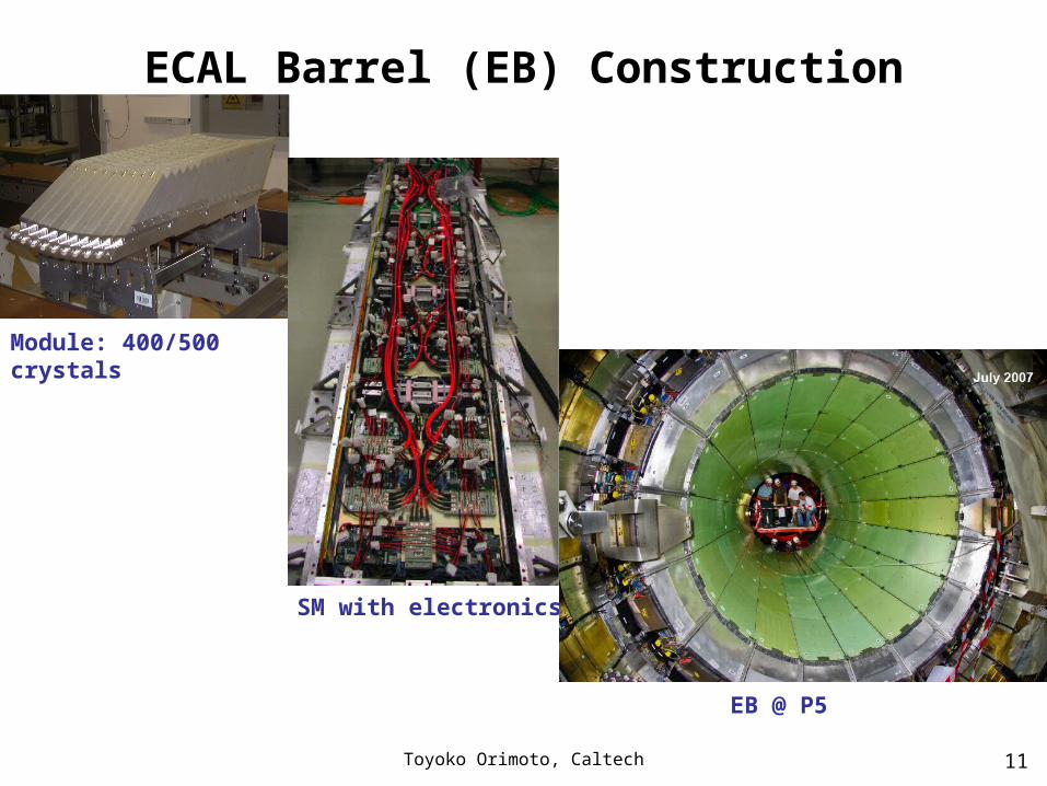
ECAL Barrel (EB) Construction
Module: 400/500 crystals
SM with electronics
EB @ P5

Toyoko Orimoto, Caltech 12
ECAL End-Cap (EE) Construction
SuperCrystal: 25 crystals
Dee (½ endcap)
EE Dee 1 & 2 @ P5

Toyoko Orimoto, Caltech 13
On-Detector Electronics
multi-channel multi-channel 12-bit ADC12-bit ADC
40 MHz40 MHz25ns sampling25ns sampling
100 m100 mFibersFibers
to to counting counting
roomroom
PbWOPbWO44
CrystalCrystalAPDAPDVPTVPT
Data pipeline Trigger
primitivesoptical data linkoptical data link
driverdriver800 Mbit/s800 Mbit/s
Trigger dataFE
Clock & Control
Multi-Gain Multi-Gain (1, 6, 12)(1, 6, 12)
Pre AmplifierPre Amplifier40 ns 40 ns
shapingshaping
x12
x6
x1MGPA
Logic
12 bit ADC
2
1
0
Energy
Light
Light
Current
Current
Voltage
Voltage
Bits
Bits
Light
DAQ data
Photodetectors:EB: Avalanche photodiodes (APD)
• Two 5x5 mm2 APDs/crystal• Gain: 50
EE: Vacuum phototriodes (VPT)• Gain 8 - 10 at B = 4 T• More rad resistant than Si diodes
13

Toyoko Orimoto, Caltech 14
The off-detector electronics is the interface between ECAL and CMS.
Off-Detector Electronics

Toyoko Orimoto, Caltech 15
Off-Detector Electronics (2)• CCS: Clock and Control System
When ECAL is turned on, loads constants into the FE and initializes the electronics; also distributes the clock to be in sync with CMS
• DCC: Data Concentration CardWhen a L1 accept is issued, the DCC merges the data from ECAL with the other sub-detectors.
• TCC: Trigger Concentration Card For ECAL trigger, computes the trigger primitive at every BX, and sends the data to the regional calorimeter trigger if energy is above threshold.
• TTS: Trigger Throttling SystemWhen a subdetector is busy and cannot accept more data, the acquisition has to stop for all sub-detectors. TTS tells each sub-detector when to stop and restart data acquisition.
• SRP: Selective Readout Processor When there is energy deposition, we don't read-out the full ECAL, only a selected area around energy deposition.

Toyoko Orimoto, Caltech 16
Calibration & Monitoring
ECAL Calibration: (Maintain Energy Resolution)
ECAL Stability (<< 0.5%):Monitored with Laser Monitoring System
Transparency Change Correction:Signal Change under Irradiation, Measured with Laser Monitoring System
Raw (uncalibrated) Supermodule: 6%-10% spread in resolution among channels
TestBeam Pre-Calibration: 0.3% (9 SM)Cosmic Pre-Calibration: 1.5-2.5% (36 SM)Lab Pre-Calibration: 4%
In-Situ Physics Calibration: 0.5% resolution
ECAL Monitoring (Monitor Stability and Measure Radiation Effects):
Without inter-calibration, the same signal (i.e. 120 GeV electron) would produce different outputs in different crystals.

Toyoko Orimoto, Caltech 17
Calibration Strategy• Will start with pre-calibration, but would
like to improve calibration quickly in-situ
• Testbeam calibration only on 9 SM for EB (~500 xtals of EE), others have couple % calibration from cosmics for EB and ~10% lab calibration for EE
• Several paths for in-situ physics calibration
MC Studies

Toyoko Orimoto, Caltech 18
Crystal Transparency Changes & Laser Monitoring System
Simulated crystal transparency changes
2 1033 cm-2 s-1
There is a change in ECAL signal during periods of irradiation due to radiation-dependent crystal transparency changes.• Dose rate at LHC nominal luminosity is
0.2-0.3 Gy/h in EB and 15 Gy/h in EE• ~5% changed must be corrected for to
maintain energy resolution of detectorLaser Monitoring System to inject light into crystals and monitor output• Will monitor transparency changes with
precision of < 0.1% every 20 minutes during LHC operation

Toyoko Orimoto, Caltech 19
2007:Individual signoff of each SM during installation
2007:Individual signoff of each SM during installation
Highlights from Commissioning Timeline
2004 2005 2006 2007 2008
2006:Test Beam @ H4:9 SM;Combined Test beam @ H2: ECAL+HCAL
2006-2007:Commissioning & calibration of each SM with cosmics on surface
2004:Test Beam @ H4:1 EB SM withfinal electronics
2006:22 SM tested with magnetic field in surface (MTCC)
2008:Commissioning with cosmics and first beam in-situ
2007:Test Beam @ H4: EE
2007:Test Beam @ H4: EE

Toyoko Orimoto, Caltech 20
Test Beam HighlightsInter-calibration (IC) with electron beam
• 9 SMs intercalibrated with electrons @ 120 GeV H4
• 1 SMs partially calibrated with electrons @ 50 GeV H2
IC reproducibility 0.2 %
%25.0108%37.3
EEE
With optimized amplitude reconstruction method

Toyoko Orimoto, Caltech 21
Cosmic Data Highlights
DTDT
EBEB
EEEEHCALHCAL
CRUZET4Data
Muon Showering in EB & EE

Toyoko Orimoto, Caltech 22
Cosmic Signal in B-Field
ECAL in magentaHCAL in blueTracker and Muon hits in green
CRAFTData

Toyoko Orimoto, Caltech 23
Cosmics Analysis: OccupancyOccupancy map of clusters in the ECAL barrel in cosmic muon runs • CRAFT Data: Magnetic field at 3.8T and the APD gain set to 200 • Clusters are seeded from a single crystal above 15 ADC counts (≈ 130
MeV) OR two adjacent crystals above 5 ADC counts (≈ 2x43 MeV). • Rate of selecting cosmics with gain 200 was ~7% during CRAFT• Other modulations due to the cluster efficiency varying with light yield.
CRAFTData
Excess in EB- region is due to position of shaft
TOP BOTTOM
Higher occup in Top & Bottom regions due to vertical cosmic ray flux.

Toyoko Orimoto, Caltech 24
Cosmics Analysis: TimingProfile map of average time associated with clusters in ECAL barrel• Time is measured in clock units (25 ns) wrt the settings for collisions.• Binned in 5x5 TTs; color corresponds to clock units.• Clusters in the bottom are seen later with respect to the top part as a
result of the time of flight of the cosmic rays.
CRAFTData
TOP BOTTOM
Top is earlier, Bottom is later

Toyoko Orimoto, Caltech 25
Cosmics Analysis: Energy SpectrumEnergy spectrum in ECAL barrel for CRAFT cosmic muon runs• Energy is obtained summing the energies of all the crystals
belonging to a cluster.• “High energy” events mostly from muon brem.• Rate of events with cluster > 2 GeV is ~ 0.3% (~4% of all cosmic
clusters)
triggered CRUZET event290 GeV cluster!
CRAFTData
200 GeV
Toyoko Orimoto, Caltech 26
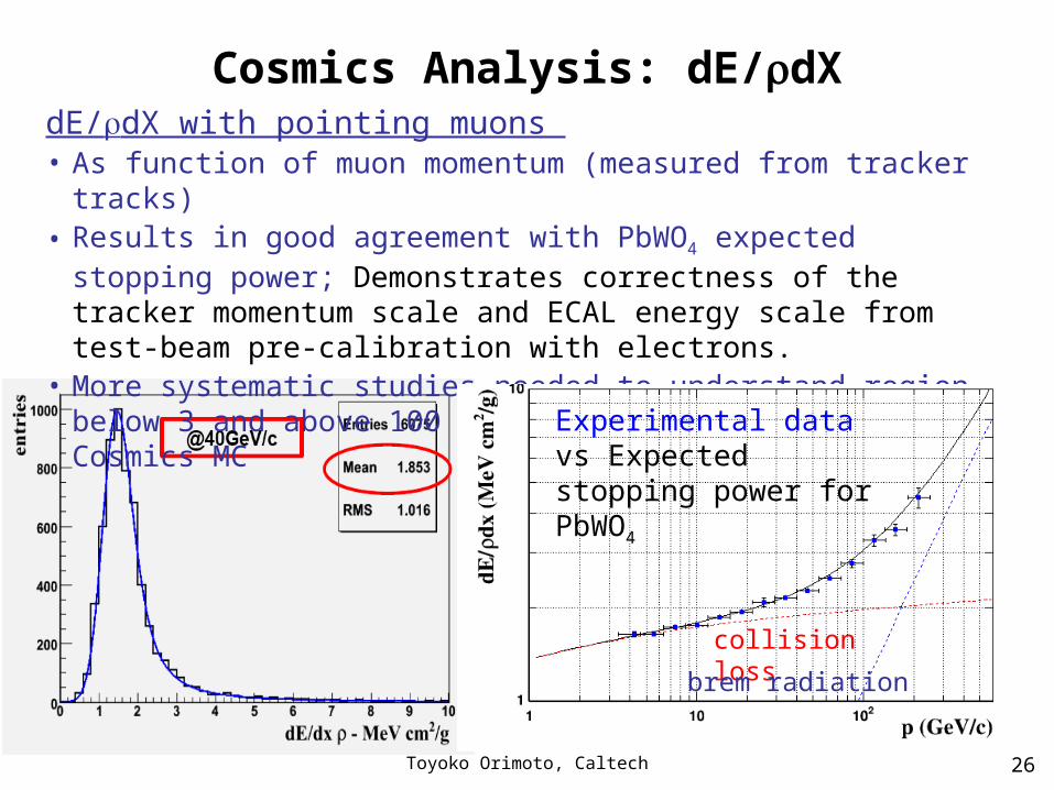
Cosmics Analysis: dE/dXdE/dX with pointing muons • As function of muon momentum (measured from tracker tracks)• Results in good agreement with PbWO4 expected stopping power;
Demonstrates correctness of the tracker momentum scale and ECAL energy scale from test-beam pre-calibration with electrons.
• More systematic studies needed to understand region below 3 and above 100 GeV/c, comparing also with Cosmics MC
collision loss
brem radiation
Experimental data vs Expected stopping power for PbWO4

Toyoko Orimoto, Caltech 27
First Beam Data: Splash Events
HCAL energy ECAL energy
Beam was sent to collimators ~150m upstream of CMS, creating a fixed target like environment at CMS, ~2x10⁹ protons on collimator

Toyoko Orimoto, Caltech 28
Beam Splash: ECAL Energy
TOP BOTTOM
EB+
EB-
> 99% of ECAL channels fired and~200 TeV energy deposited in EB+EE
Beam (clockwise) came from plus side.
Around 200k muons crossing ECAL per event (~4 muons/cm2).
EE pre-calibrations were yet applied (lowest gain photodetectors are nearest the beam pipe).
Toyoko Orimoto, Caltech 29
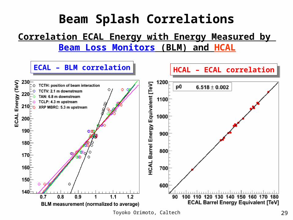
Beam Splash Correlations
ECAL – BLM correlationECAL – BLM correlationHCAL – ECAL correlationHCAL – ECAL correlation
Correlation ECAL Energy with Energy Measured by Beam Loss Monitors (BLM) and HCAL

Toyoko Orimoto, Caltech 30
Conclusions
• ECAL Barrel & Endcap
• Commissioned and have been regularly taking data for many months now; Participated in all global runs (CRUZET-CRAFT)
• Millions of cosmic data to analyze (on-going)
• Successful observation of first beam data at LHC; utilizing this data as much as possible
• Plans for next months
• Installation and commissioning of pre-shower
• EE trigger installation
• Hardware issues: LV, FE problems, etc need to be resolved
• Ready analyses for beam: calibration, prompt feedback

Toyoko Orimoto, Caltech 31
Interested in Joining the ECAL PFG?ECAL Prompt Feedback Group (PFG)• Great place for newcomers to start; many young students have
started their work on CMS with our group.
• Great way to gain ECAL expertise, but also to learn how to access and analyze data quickly, trouble shoot problems, etc…
• Most of the results shown today have been produced by the PFG
• Prerequisites are a basic knowledge of CMSSW and ECAL, availability to take on-duty shifts and attend PFG meetings; also, your institution should be a part of ECAL Group.
Toyoko Orimoto, Caltech 32
Reference Links
• CMS 101 Workshop (very nice ECAL intro):
http://indico.cern.ch/conferenceDisplay.py?confId=35545
• LPC Run Plan Workshop (ECAL Talk, a bit outdated):http://indico.cern.ch/getFile.py/access?resId=0&materialId=slides&contribId=44&sessionId=7&subContId=2&confId=30825
• ECAL Cosmics Analysis Tutorial (also a bit outdated but still interesting and informative):http://indico.cern.ch/contributionDisplay.py?contribId=4&confId=32360
• ECAL CRAFT Results:http://indico.cern.ch/conferenceDisplay.py?confId=46935
• ECAL TDR:
http://cmsdoc.cern.ch/ftp/TDR/ECAL/ecal.html

Toyoko Orimoto, Caltech 33
Extra Slides

Toyoko Orimoto, Caltech 34
CMS Rapidity Coverage
Toyoko Orimoto, Caltech 35
Toyoko Orimoto, Caltech 36
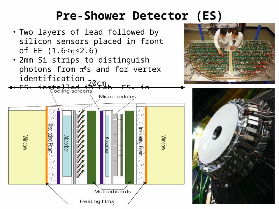
Pre-Shower Detector (ES)• Two layers of lead followed by silicon
sensors placed in front of EE (1.6<<2.6)• 2mm Si strips to distinguish photons from 0s
and for vertex identification• ES+ installed in Feb, ES- in March
20cm

Toyoko Orimoto, Caltech 37
Photo Detectors
20
Barrel : Avalanche photodiodes (APD)•Two 5x5 mm2 APDs/crystal•Gain: 50•Temperature dependence: -2.4%/OC
Endcaps: Vacuum phototriodes (VPT)•Active area ~ 280 mm2/crystal•Gain 8 - 10 at B = 4 T•More radiation resistant than Si diodes (with UV glass window)
APD VPT
PWO4 has a very low light output, need to amplify signal.
Problem: Limited space and 4T field
Solution: A photon-to-current device with built-in gain

Toyoko Orimoto, Caltech 38
Toyoko Orimoto, Caltech 39
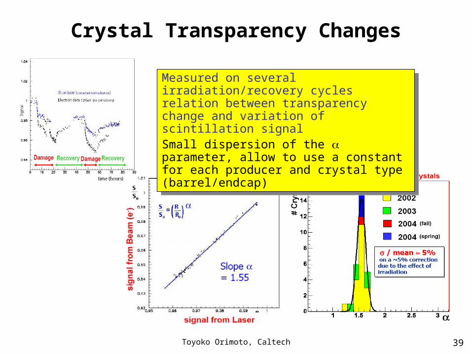
Crystal Transparency Changes
Measured on several irradiation/recovery cycles relation between transparency change and variation of scintillation signalSmall dispersion of the parameter, allow to use a constant for each producer and crystal type (barrel/endcap)
Measured on several irradiation/recovery cycles relation between transparency change and variation of scintillation signalSmall dispersion of the parameter, allow to use a constant for each producer and crystal type (barrel/endcap)
Toyoko Orimoto, Caltech 40
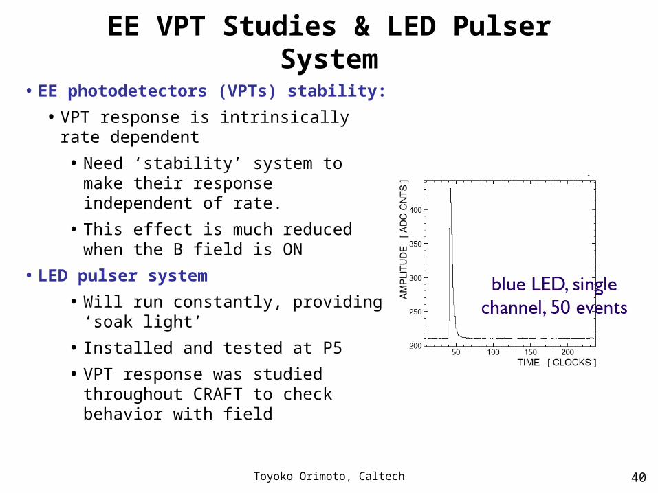
EE VPT Studies & LED Pulser System
• EE photodetectors (VPTs) stability:
• VPT response is intrinsically rate dependent
• Need ‘stability’ system to make their response independent of rate.
• This effect is much reduced when the B field is ON
• LED pulser system
• Will run constantly, providing ‘soak light’
• Installed and tested at P5
• VPT response was studied throughout CRAFT to check behavior with field
Toyoko Orimoto, Caltech 41
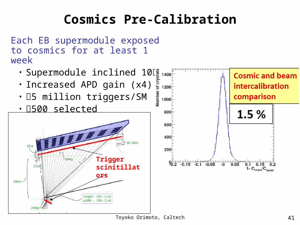
Cosmics Pre-Calibration
Each EB supermodule exposed to cosmics for at least 1 week
• Supermodule inclined 10• Increased APD gain (x4)• 5 million triggers/SM• 500 selected events/crystal
Trigger scinitillators
Toyoko Orimoto, Caltech 42
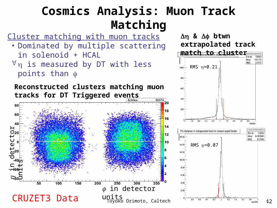
Cosmics Analysis: Muon Track Matching
in detector units
in
det
ecto
r un
its
Cluster matching with muon tracks• Dominated by multiple scattering in solenoid
+ HCAL is measured by DT with less points than
Reconstructed clusters matching muon tracks for DT Triggered events
RMS =0.21
RMS =0.07
& btwn extrapolated track match to cluster
CRUZET3 Data