toyota vehicle intrusion protection 01 05–700 diagnostics – toyota vehicle intrusion...
TRANSCRIPT

057RT–01
05–700 –DIAGNOSTICS TOYOTA VEHICLE INTRUSION PROTECTIONSYSTEM
865Author�: Date�:
2004 COROLLA (RM1037U)
TOYOTA VEHICLE INTRUSION PROTECTION SYSTEMHOW TO PROCEED WITH TROUBLESHOOTINGTroubleshoot in accordance with the procedure on the following pages.
1 VEHICLE BROUGHT TO WORKSHOP
2 CUSTOMER PROBLEM ANALYSIS CHECK AND SYMPTOM CHECK(See page 05–701)
(a) Without applicable symptoms, proceed to ”A”.(b) With applicable symptoms, proceed to ”B”.
B Go to step 4
A
3 SYMPTOM SIMULATION
4 PROBLEM SYMPTOMS TABLE (See page 05–707)
(a) Without applicable symptoms, proceed to ”A”.(b) With applicable symptoms, proceed to ”B”.
B Go to step 5
A
5 CIRCUIT INSPECTION AND PART INSPECTION (See page 05–707)
6 PERFORM TROUBLESHOOTING IN THE FOLLOWING METHOD, DEPENDING ONMALFUNCTION SYMPTOM
(a) Terminals of ECU (Seepage 05–703)(b) On–vehicle inspection (Seepage 73–14)
7 ADJUSTMENT, REPAIR OR REPLACEMENT
8 CONFIRMATION TEST
END
057RU–01
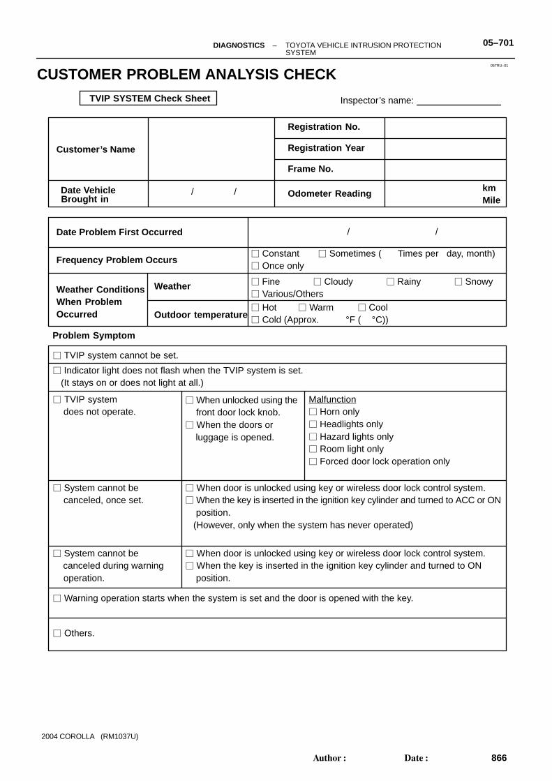
TVIP SYSTEM Check Sheet Inspector’s name:
Customer’s Name
Date Vehicle
Registration No.
Registration Year
Frame No.
Odometer Reading / / kmMile
Weather ConditionsWhen ProblemOccurred
Frequency Problem Occurs
Weather
Outdoor temperature
/ /
� Constant � Sometimes ( Times per day, month)� Once only
Brought in
� TVIP system cannot be set.
� Indicator light does not flash when the TVIP system is set. (It stays on or does not light at all.)
� TVIP system does not operate.
� When unlocked using the front door lock knob.� When the doors or luggage is opened.
� System cannot be canceled, once set.
� When door is unlocked using key or wireless door lock control system.� When the key is inserted in the ignition key cylinder and turned to ACC or ON position. (However, only when the system has never operated)
� System cannot be canceled during warning operation.
� When door is unlocked using key or wireless door lock control system.� When the key is inserted in the ignition key cylinder and turned to ON position.
� Warning operation starts when the system is set and the door is opened with the key.
� Others.
Date Problem First Occurred
� Fine � Cloudy � Rainy � Snowy� Various/Others
� Hot � Warm � Cool� Cold (Approx. °F ( °C))
Problem Symptom
Malfunction� Horn only� Headlights only� Hazard lights only� Room light only� Forced door lock operation only
–DIAGNOSTICS TOYOTA VEHICLE INTRUSION PROTECTIONSYSTEM
05–701
866Author�: Date�:
2004 COROLLA (RM1037U)
CUSTOMER PROBLEM ANALYSIS CHECK

057RV–01
B58634
Horn Low Pitched Horn Assy (Horn)
Engine Room J/B� HORN Fuse� HORN Relay� Headlight Control Relay
Headlight
TVIP ECU
Ignition Switch� Key Unlock Warning Switch
Security Indicator(w/ Glass Breakage Sensor)
Starter Cut Relay
Glass Breakage Sensor ECU
Instrument Panel J/B (Integration Relay)
Front Door w/ Motor Lock Assy LH(Door Unlock Detection Switch)
Luggage Door Lock Assy(Luggage Compartment Light Switch)
Hazard Warning Light
Room Light
Courtesy Lamp Switch Assy Front LH
Front Door w/ Motor Lock Assy RH(Door Unlock Detection Switch)
Rear Door w/ Motor Lock Assy RH
Courtesy Lamp Switch Assy Front RH
Courtesy Lamp Switch Assy Rear LH
Hazard Warning Signal Switch
Courtesy Lamp Switch Assy Rear RH
Hazard Warning Light
Rear Door w/ Motor Lock Assy LH
05–702 –DIAGNOSTICS TOYOTA VEHICLE INTRUSION PROTECTIONSYSTEM
867Author�: Date�:
2004 COROLLA (RM1037U)
LOCATION

057RW–01
B50657
T3
–DIAGNOSTICS TOYOTA VEHICLE INTRUSION PROTECTIONSYSTEM
05–703
868Author�: Date�:
2004 COROLLA (RM1037U)
TERMINALS OF ECU1. INSPECT TVIP ECU
(a) Inspect the ECU–B, DOME and ECU–IG fuses.(b) Disconnect the TVIP ECU connector, and the continuity and voltage of check each terminal of the dis-
connected connector.Standard:
Symbols (Terminal No.) Wiring Color Condition Specified Condition
+B1 (T3–2) ⇔ E (T3–29)
R–B ⇔ W–B Constant 10 – 14 V
CTY (T3–19) ⇔ E (T3–29)
R ⇔ W–B�Passenger’s door fully closed → Opened�Rear right door fully closed → Opened�Rear left door fully closed → Opened
No continuity → Continuity
DSWD (T3–40) ⇔ E (T3–29)
R–W ⇔ W–B Driver’s door fully closed → Opened No continuity → Continuity
DSWL (T3–35) ⇔ E (T3–29)
R–W ⇔ W–B Luggage’s door fully closed → Opened No continuity → Continuity
KSW (T3–12) ⇔ E (T3–29)
L–B ⇔ W–B No key in ignition switch lock cylinder → Key inserted 0 V → 10 – 14 V
L2 (T3–16) ⇔ E (T3–29)
G ⇔ W–B Driver’s door lock UNLOCK → LOCK0 V → 10 – 14 V
→ 1 V or less
UL3 (T3–17) ⇔ E (T3–29)
L–Y⇔ W–B Driver’s door lock LOCK → UNLOCK0 V → 10 – 14 V
→ 1 V or less
UL2 (T3–18) ⇔ E (T3–29)
L–B⇔ W–B Passenger’s door lock LOCK → UNLOCK0 V → 10 – 14 V
→ 1 V or less
IRSG (T3–28) ⇔ E (T3–29)
W ⇔ W–B Driver’s door lock LOCK → UNLOCK Pulse generation
IG (T3–10) ⇔ E (T3–29)
B–W ⇔ W–B Ignition switch OFF → ON 0 V → 10 – 14 V
SRLY (T3–21) ⇔ E (T3–29)
B–R ⇔ W–B Ignition switch OFF → ON 0 V → 10 – 14 V
LSWD (T3–37) ⇔ E (T3–29)
W ⇔ W–B Driver’s door lock UNLOCK → LOCK 0 V → 10 – 14 V
LSWP (T3–38) ⇔ E (T3–29)
W–R ⇔ W–B Passenger’s door lock UNLOCK → LOCK 0 V → 10 – 14 V
If the result is not as specified, the vehicle’s side may malfunction.

B57790
Integration Relay Connector(Wire Harness Side)
I11
05–704 –DIAGNOSTICS TOYOTA VEHICLE INTRUSION PROTECTIONSYSTEM
869Author�: Date�:
2004 COROLLA (RM1037U)
(c) Reconnect the TVIP ECU connector, and the continuity and voltage of check each terminal of the dis-connected connector.Standard:
Symbols (Terminal No.) Wiring Color Condition Specified Condition
DMLP (T3–9) ⇔ E (T3–29)
R–W ⇔ W–B Armed state → Alarm sounding state Pulse generation
HEAD (T3–6) ⇔ E (T3–29)
R ⇔ W–B Light control switch position HEAD → OFF or TAIL 1 V or less → 10 – 14 V
HAZD (T3–8) ⇔ E (T3–29)
Y–B ⇔ W–B Armed state → Alarm sounding state Pulse generation
IND (T3–25) ⇔ E (T3–29)
R–W ⇔ W–BSecurity indicator light lights up.(It lights up only for 30 sec.)
10 – 14 V
IOUT (T3–11) ⇔ E (T3–29)
L ⇔ W–BArmed state → Alarm sounding state (on grass breakage detection)
Pulse generation
HORN (T3–5) ⇔ E (T3–29)
G–Y ⇔ W–B Armed state → Alarm sounding state Pulse generation
E (T3–29) ⇔ Body ground
W–B ⇔ Body ground Constant Continuity
If the result is not as specified, the TVIP ECU may malfunction.2. INSPECT INTEGRATION RELAY
(a) Disconnect the connector and check the continuity of each terminal of the disconnected connector.
Symbols (Terminal No.) Wiring color Condition Specified Condition
PCTY (I11–13) ⇔ Body ground
R–W ⇔ Body ground Passenger’s door fully closed → Opened No continuity → Continuity
If the result is not as specified, the vehicle’s side may malfunction.

B59376
B59378
B59532
Instrument Panel J/B Side
IF
Instrument Panel J/B (Integration Relay)
ID
IH
IJ
Instrument Panel J/B Side
Instrument Panel J/B Side
Instrument Panel J/B SideConnector IF
Connector ID Connector IH
Connector IJ
IK
Instrument Panel J/B SideConnector IK
Instrument Panel J/B SideConnector IA
IA
IBInstrument Panel J/B Side
Connector IB
–DIAGNOSTICS TOYOTA VEHICLE INTRUSION PROTECTIONSYSTEM
05–705
870Author�: Date�:
2004 COROLLA (RM1037U)
3. INSPECT INSTRUMENT PANEL J/B (INTEGRATION RELAY)

05–706 –DIAGNOSTICS TOYOTA VEHICLE INTRUSION PROTECTIONSYSTEM
871Author�: Date�:
2004 COROLLA (RM1037U)
(a) Inspect the DOOR fuse.(b) Disconnect the ID connector of the instrument panel J/B, and check the continuity of each terminal of
the disconnected connectors.Standard:
Symbols (Terminal No.) Wiring color Condition Specified Condition
DCTY (ID–1) ⇔ Body ground
R–W ⇔ Body ground Driver’s door fully closed → Opened
PRCTY (ID–14) ⇔ Body ground
R–B ⇔ Body ground Rear LH door fully closed → Opened No continuity → Continuity
PRCTY (ID–15) ⇔ Body ground
R–Y ⇔ Body ground Rear RH door fully closed → Opened
If the result is not as specified, the vehicle’s side may malfunction.

057RX–01
–DIAGNOSTICS TOYOTA VEHICLE INTRUSION PROTECTIONSYSTEM
05–707
872Author�: Date�:
2004 COROLLA (RM1037U)
PROBLEM SYMPTOMS TABLEProceed to the reference page shown in the table below for each malfunction symptom and troubleshooteach circuit.HINT:Troubleshooting of the TVIP system is based on the premise that the door lock control system and wirelessdoor lock control system is operating normally. Accordingly, before troubleshooting the TVIP system, firstmake certain that the door lock control system and wireless door lock control system is operating normally.
Symptom Suspected Area See page
TVIP system cannot be set
1. Indicator light circuit
2. ECU power source circuit
3. Key unlock warning switch circuit
4. Door key lock and unlock switch circuit
5. Door unlock detection switch circuit
6. Door courtesy switch circuit
7. TVIP ECU communication circuit
05–708
05–710
05–727
05–738
05–736
05–733
05–740
Indicator light does not blink when TVIP system is set. 1. Indicator light circuit 05–708
TVIP system does not operate when front door is unlocked (whenTVIP system is set).
1. Door unlock detection switch circuit 05–736
TVIP system is not canceled when ignition key is turned to ONposition (when TVIP system is set).
1. Ignition switch circuit
2. Key unlock warning switch circuit
05–713
05–727
TVIP system still operates when door is opened with key (whenTVIP system is set).
1. Door key lock and unlock switch circuit
2. Door unlock detection switch circuit
05–738
05–736
Horns do not sound while TVIP system is in warning operation. 1. Horn relay circuit 05–716
Headlights do not flash while TVIP system is in warningoperation.
1. Light control switch circuit 05–719
Hazard warning do not flash while TVIP system is in warningoperation.
1. Hazard warning switch circuit 05–722
Door is not locked while TVIP system is in warning operation. 1. Door unlock detection switch circuit 05–736
TVIP system is still set even when rear door is open 1. Door courtesy switch circuit 05–733
Horns sound even when TVIP system is not set. 1. Horn relay circuit 05–716
Headlights stay on even when TVIP system is not set. 1. Light control switch circuit 05–719
Hazard warning stays on even when TVIP system is not set. 1. Hazard warning switch circuit 05–722

B59175
TVIP ECU
IND25
3AW–B
T3IND
GND
R–W
J7J/C
RH J/B
19 11
A
IG
2
1
S4Security Indicator
W–B3A
B59187
Security Indicator
05–708 –DIAGNOSTICS TOYOTA VEHICLE INTRUSION PROTECTIONSYSTEM
873Author�: Date�:
2004 COROLLA (RM1037U)
INDICATOR LIGHT CIRCUIT
CIRCUIT DESCRIPTIONWhen the TVIP system is preparing to be set, this circuit lights up the indicator light. When the system hasbeen set, it continually turns the indicator light on for 0.2 seconds and turns it off for 1.8 seconds, thus theindicator light blinks.
WIRING DIAGRAM
INSPECTION PROCEDURE
1 CHECK SECURITY INDICATOR LIGHT
(a) Remove the security indicator.(b) Check the indicator light, as shown in the illustration and
table.Standard:
Measuring condition Operation
Battery positive (+) ⇔ Terminal 2Battery negative (–) ⇔ Terminal 1
Indicator light comes on
NG REPLACE SECURITY INDICATOR LIGHT
OK
057RY–01

B52239
B59192 B59594
Security Indicator
TVIP ECU (Wire Harness Side)
T3
S4
(Wire Harness Side)
IND
IND (T3–25)
B59192
Security IndicatorS4(Wire Harness Side)
GND
–DIAGNOSTICS TOYOTA VEHICLE INTRUSION PROTECTIONSYSTEM
05–709
874Author�: Date�:
2004 COROLLA (RM1037U)
2 CHECK WIRE HARNESS (TVIP ECU ⇔ SECURITY INDICATOR)
(a) Disconnect the TVIP ECU and security indicator connec-tors.
(b) Check the continuity between the terminals of the TVIPECU connector and security indicator connector, asshown in the illustration and table.Standard:
Symbols (Terminal No.) (TVIP ECU ⇔ Security indicator)
Specified condition
IND (T3–25) ⇔ IND (S4–2) Continuity
NG REPAIR OR REPLACE WIRE HARNESS ANDCONNECTOR
OK
3 CHECK WIRE HARNESS (SECURITY INDICATOR ⇔ BODY GROUND)
(a) Disconnect the security indicator connector.(b) Check the continuity between the terminal of the security
indicator connector and body ground, as shown in the il-lustration and table.Standard:
Symbol (Terminal No.) (Security indicator ⇔ Body ground)
Specified condition
GND (S4–1) ⇔ Body ground Continuity
NG REPAIR OR REPLACE WIRE HARNESS ANDCONNECTOR
OK
CHECK AND REPLACE TVIP ECU (See page 01–30)

I24315 B59176
TVIP ECU
+B1
E
FL MAIN
Battery
2
29
W
Engine Room J/B
RH J/B
W–B
B1
1A11C
ALT
1 2
1IB
1IH
ECU–B
Instrument Panel J/B
R–BT3
T3113A
193A
W–B
A
IG
J7J/C
05–710 –DIAGNOSTICS TOYOTA VEHICLE INTRUSION PROTECTIONSYSTEM
875Author�: Date�:
2004 COROLLA (RM1037U)
ECU POWER SOURCE CIRCUIT
CIRCUIT DESCRIPTIONThis circuit provides power to operate the TVIP ECU.
WIRING DIAGRAM
057RZ–02

I24329ECU–B Fuse
Instrument Panel J/B
B52239
+B1 (2)T3
E (29)
TVIP ECU
–DIAGNOSTICS TOYOTA VEHICLE INTRUSION PROTECTIONSYSTEM
05–711
876Author�: Date�:
2004 COROLLA (RM1037U)
INSPECTION PROCEDURE
1 CHECK FUSE (ECU–B)
(a) Remove the fuse from the instrument panel J/B.(b) Check the continuity of the fuse.
Standard: Continuity
NG REPLACE FUSE
OK
2 CHECK TVIP ECU
(a) Disconnect the TVIP ECU connector.(b) Measure the voltage between the terminals of the ECU
connector, as shown in the illustration and table.Standard:
Symbols (Terminal No.) Specified condition
+B1 (T3–2) ⇔ E (T3–29) 10 – 14 V
E (T3–29) ⇔ Body ground 0 V
NG PROCEED TO NEXT CIRCUIT INSPECTIONSHOWN ON PROBLEM SYMPTOMS TABLE (See page 05–707)
OK

B52239
T3
E (29)
TVIP ECU
05–712 –DIAGNOSTICS TOYOTA VEHICLE INTRUSION PROTECTIONSYSTEM
877Author�: Date�:
2004 COROLLA (RM1037U)
3 CHECK WIRE HARNESS (TVIP ECU ⇔ BODY GROUND)
(a) Disconnect the TVIP ECU connector.(b) Check the connector on the harness side, as shown in the
illustration and table.Standard:
Symbols (Terminal No.) Specified condition
E (T3–29) ⇔ Body ground Continuity
NG REPAIR OR REPLACE WIRE HARNESS ANDCONNECTOR
OK
CHECK AND REPLACE TVIP ECU (See page 01–30)

B59177
10IG
FL MAIN
Battery
Instrument Panel J/B
IG1 RelayECU–IG 9
IF B–W
W–B
W
B–YAM1 IG1
I10Ignition SW
ALT
Engine Room J/B
11C
J6J/C
A
IE
1 2
W
11D
J7J/C
A
IG
12
11A B
T3
10IH
4IF
1IB
35
1 2
1
2IF
12IF
AM1
W
W–B
IA
TVIP ECU
–DIAGNOSTICS TOYOTA VEHICLE INTRUSION PROTECTIONSYSTEM
05–713
878Author�: Date�:
2004 COROLLA (RM1037U)
IGNITION SWITCH CIRCUIT
CIRCUIT DESCRIPTIONIf the ignition switch is turned to the ON position, battery positive voltage is applied to the switches, such asterminal IG of the ECU.
WIRING DIAGRAM
057S0–01

B51200
I24329ECU–B Fuse
Instrument Panel J/B
B16200
05–714 –DIAGNOSTICS TOYOTA VEHICLE INTRUSION PROTECTIONSYSTEM
879Author�: Date�:
2004 COROLLA (RM1037U)
INSPECTION PROCEDURE
1 CHECK IGNITION OR STARTER SWITCH ASSY
(a) Check the ignition switch, as shown in the illustration andtable.Standard:Terminal No. Switch position Specified condition
– LOCK –
1 ⇔ 3 ACC Continuity
1 ⇔ 2 ⇔ 3ON Continuity
1 ⇔ 2 ⇔ 35 ⇔ 6
ON Continuity
1 ⇔ 2START Continuity
1 ⇔ 24 ⇔ 5 ⇔ 6
START Continuity
NG REPAIR OR REPLACE IGNITION OR STARTERSWITCH ASSY
OK
2 CHECK FUSE (ECU–B)
(a) Remove the fuse from the instrument panel J/B.(b) Check the continuity of the fuse.
Standard: Continuity
NG REPLACE FUSE
OK
3 CHECK RELAY (Marking: IG1)
(a) Remove the relay from the instrument J/B.(b) Inspect the relay continuity, as shown in the illustration
and table.Standard:Terminal No. Condition Specified condition
1 ⇔ 2 Constant Continuity
3 ⇔ 5Apply B+ betweenterminals 1 and 2
Continuity
NG REPLACE RELAY
OK

B52239
T3 IG (10)
TVIP ECU
–DIAGNOSTICS TOYOTA VEHICLE INTRUSION PROTECTIONSYSTEM
05–715
880Author�: Date�:
2004 COROLLA (RM1037U)
4 CHECK TVIP ECU
(a) Disconnect the TVIP ECU connector.(b) Turn the ignition switch ON.(c) Measure the voltage between the terminal of the ECU
connector and the body ground, as shown in the illustra-tion and table.Standard:
Symbols (Terminal No.) Specified condition
IG (T3–10) ⇔ Body ground 10 – 14 V
NG REPAIR OR REPLACE WIRE HARNESS ANDCONNECTOR
OK
CHECK AND REPLACE TVIP ECU (See page 01–30)
B59178
TVIP ECU
C10CombinationSW
Engine Room J/B and R/B
HORN5T3G–Y
18IA5
B
HornBattery
FL MAINB
HORN Relay
B–W
13 5
12
HORN
G–Y
1
B–W1
1 2
11A
1
1
1
1
G–Y
G–YG–Y
Center J/B
4A12
4A13
H6Horn Low Pitched Horn Assy (Horn)
05–716 –DIAGNOSTICS TOYOTA VEHICLE INTRUSION PROTECTIONSYSTEM
881Author�: Date�:
2004 COROLLA (RM1037U)
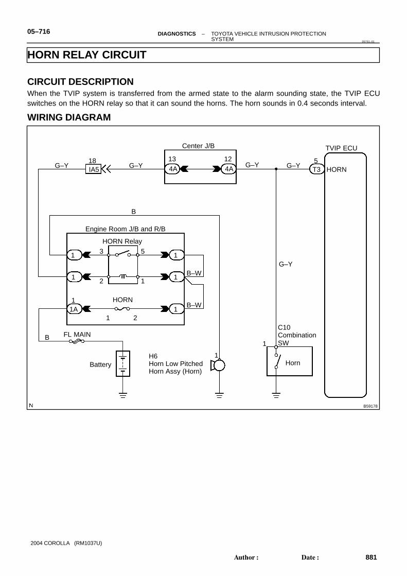
HORN RELAY CIRCUIT
CIRCUIT DESCRIPTIONWhen the TVIP system is transferred from the armed state to the alarm sounding state, the TVIP ECUswitches on the HORN relay so that it can sound the horns. The horn sounds in 0.4 seconds interval.
WIRING DIAGRAM
057S1–01
I11656
B16200
–DIAGNOSTICS TOYOTA VEHICLE INTRUSION PROTECTIONSYSTEM
05–717
882Author�: Date�:
2004 COROLLA (RM1037U)
INSPECTION PROCEDURE
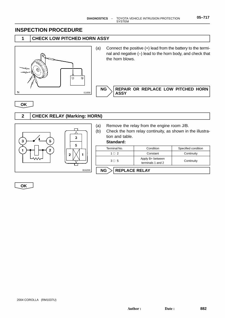
1 CHECK LOW PITCHED HORN ASSY
(a) Connect the positive (+) lead from the battery to the termi-nal and negative (–) lead to the horn body, and check thatthe horn blows.
NG REPAIR OR REPLACE LOW PITCHED HORNASSY
OK
2 CHECK RELAY (Marking: HORN)
(a) Remove the relay from the engine room J/B.(b) Check the horn relay continuity, as shown in the illustra-
tion and table.Standard:Terminal No. Condition Specified condition
1 ⇔ 2 Constant Continuity
3 ⇔ 5Apply B+ betweenterminals 1 and 2
Continuity
NG REPLACE RELAY
OK
B59602
B52239
B59603
TVIP ECU (Wire Harness Side)
T3
Horn (5)
Engine Room J/B
1 2
35
Horn Relay
B59193
B59602
B59595
HornH6
(Wire Harness Side)
Engine Room J/B
1 2
35
HORN Relay
05–718 –DIAGNOSTICS TOYOTA VEHICLE INTRUSION PROTECTIONSYSTEM
883Author�: Date�:
2004 COROLLA (RM1037U)
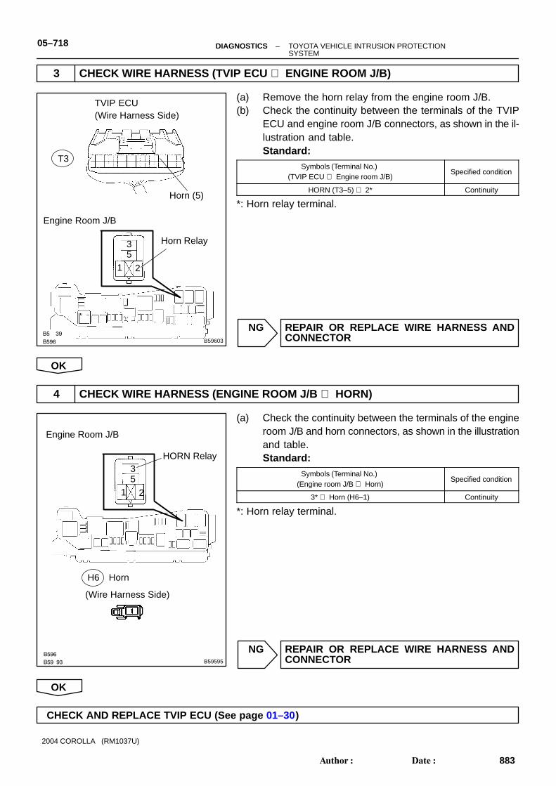
3 CHECK WIRE HARNESS (TVIP ECU ⇔ ENGINE ROOM J/B)
(a) Remove the horn relay from the engine room J/B.(b) Check the continuity between the terminals of the TVIP
ECU and engine room J/B connectors, as shown in the il-lustration and table.Standard:
Symbols (Terminal No.) (TVIP ECU ⇔ Engine room J/B)
Specified condition
HORN (T3–5) ⇔ 2* Continuity
*: Horn relay terminal.
NG REPAIR OR REPLACE WIRE HARNESS ANDCONNECTOR
OK
4 CHECK WIRE HARNESS (ENGINE ROOM J/B ⇔ HORN)
(a) Check the continuity between the terminals of the engineroom J/B and horn connectors, as shown in the illustrationand table.Standard:
Symbols (Terminal No.) (Engine room J/B ⇔ Horn)
Specified condition
3* ⇔ Horn (H6–1) Continuity
*: Horn relay terminal.
NG REPAIR OR REPLACE WIRE HARNESS ANDCONNECTOR
OK
CHECK AND REPLACE TVIP ECU (See page 01–30)

B59179
TVIP ECU
C12Combination SW(Light Control Switch)
HEAD6T3
IE
AJ6J/C
W–B*1
10
214B
R
12
LightControlSW
OFF
Tail
Head
+B T RF H EL
Center J/B
G*2
114B
2IC
Instrument Panel J/B
2IL
W–B*1
J1J/C
G*2
G*2
W–B
F4Front Parking Light RH
F3Front Parking Light LH
ED EA
*1: USA*2: Canada
G A
A1
2
1
2
A
–DIAGNOSTICS TOYOTA VEHICLE INTRUSION PROTECTIONSYSTEM
05–719
884Author�: Date�:
2004 COROLLA (RM1037U)
LIGHT CONTROL SWITCH CIRCUIT
WIRING DIAGRAM
057S2–03

B59189
B52239
B59592
Light Control Switch
TVIP ECU (Wire Harness Side)
T3
C12
(Wire Harness Side)
HEAD (6)
RF (12)
05–720 –DIAGNOSTICS TOYOTA VEHICLE INTRUSION PROTECTIONSYSTEM
885Author�: Date�:
2004 COROLLA (RM1037U)
INSPECTION PROCEDURE
1 CHECK HEADLAMP DIMMER SWITCH ASSY (LIGHT CONTROL SWITCH) (See page 65–7)
NG REPLACE HEADLAMP DIMMER SWITCH ASSY(LIGHT CONTROL SWITCH)
OK
2 CHECK WIRE HARNESS (TVIP ECU ⇔ LIGHT CONTROL SWITCH)
(a) Disconnect the TVIP ECU and light control switch con-nectors.
(b) Check the continuity between the terminals of the TVIPECU and light control switch connectors, as shown in theillustration and table.Standard:
Symbols (Terminal No.) (TVIP ECU ⇔ Light control switch)
Specified condition
HEAD (T3–6) ⇔ RF (C12–12) Continuity
NG REPAIR OR REPLACE WIRE HARNESS ANDCONNECTOR
OK

B59189
Light Control SwitchC12
(Wire Harness Side)
T (10)
–DIAGNOSTICS TOYOTA VEHICLE INTRUSION PROTECTIONSYSTEM
05–721
886Author�: Date�:
2004 COROLLA (RM1037U)
3 CHECK WIRE HARNESS (LIGHT CONTROL SWITCH ⇔ BODY GROUND)
(a) Disconnect the light control switch connector.(b) Check the continuity between the terminal of the light con-
trol switch connector and the body ground, as shown inthe illustration and table.Standard:
Symbols (Terminal No.) (Light control switch ⇔ Body ground)
Specified condition
T (C12–10) ⇔ Body ground Continuity
NG REPAIR OR REPLACE WIRE HARNESS ANDCONNECTOR
OK
PROCEED TO NEXT CIRCUIT INSPECTION SHOWN ON PROBLEM SYMPTOMS TABLE(See page 05–707)
B59180
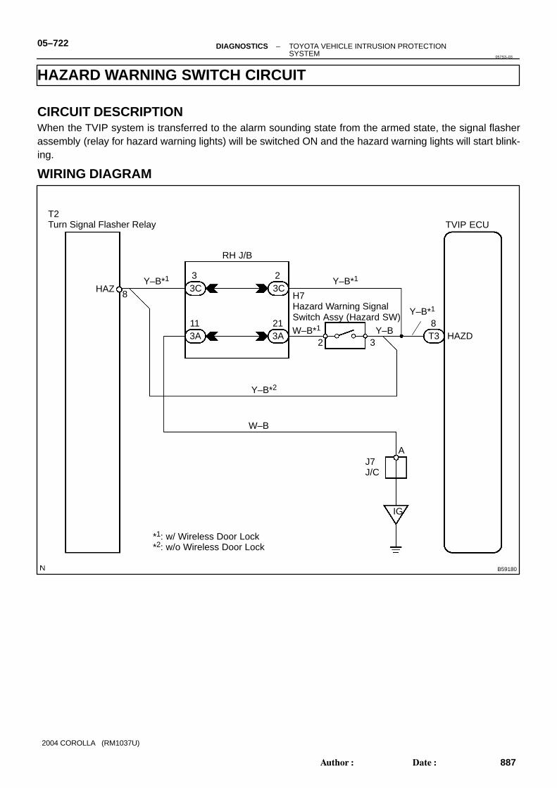
TVIP ECU
*1: w/ Wireless Door Lock*2: w/o Wireless Door Lock
HAZD8T3
T2Turn Signal Flasher Relay
H7Hazard Warning Signal Switch Assy (Hazard SW)
RH J/B
Y–B*1
23C
2 3
A
IG
J7J/C
HAZ 8
Y–B
Y–B*1
W–B
W–B*1
33C
213A
113A
Y–B*1
Y–B*2
05–722 –DIAGNOSTICS TOYOTA VEHICLE INTRUSION PROTECTIONSYSTEM
887Author�: Date�:
2004 COROLLA (RM1037U)
HAZARD WARNING SWITCH CIRCUIT
CIRCUIT DESCRIPTIONWhen the TVIP system is transferred to the alarm sounding state from the armed state, the signal flasherassembly (relay for hazard warning lights) will be switched ON and the hazard warning lights will start blink-ing.
WIRING DIAGRAM
057S3–03

B59609
No Pin (6)
No Pin (1)
B59600
B52239
B59593
Turn Signal Flasher Relay (Wire Harness Side)
T2
TVIP ECU (Wire Harness Side)
T3
HAZD (8)
HAZ (8)
–DIAGNOSTICS TOYOTA VEHICLE INTRUSION PROTECTIONSYSTEM
05–723
888Author�: Date�:
2004 COROLLA (RM1037U)
INSPECTION PROCEDURE
1 CHECK HAZARD WARNING SIGNAL SWITCH ASSY
(a) Check the hazard warning switch continuity, as shown inthe illustration and table.Standard:Terminal No. Switch position Specified condition
– Switch OFF Continuity
2 ⇔ 3 Switch ON Continuity
4 ⇔ 5 Illumination circuit Continuity4 ⇔ 5 Illumination circuit Continuity
NG REPLACE HAZARD WARNING SIGNAL SWITCHASSY
OK
2 CHECK TURN SIGNAL FLASHER ASSY (See page 65–4)
NG REPLACE TURN SIGNAL FLASHER ASSY
OK
3 CHECK WIRE HARNESS (TVIP ECU ⇔ TURN SIGNAL FLASHER)
(a) Disconnect the TVIP ECU and turn signal flasher connec-tors.
(b) Check the continuity between the terminals of the TVIPECU and turn signal flasher connectors, as shown in theillustration and table.Standard:
Symbols (Terminal No.) (TVIP ECU ⇔ Turn Signal Flasher)
Specified condition
HAZD (T3–8) ⇔ HAZ (T2–8) Continuity
NG REPAIR OR REPLACE WIRE HARNESS ANDCONNECTOR
OK
B31237
Hazard Warning Switch(Wire Harness Side)
H7
05–724 –DIAGNOSTICS TOYOTA VEHICLE INTRUSION PROTECTIONSYSTEM
889Author�: Date�:
2004 COROLLA (RM1037U)
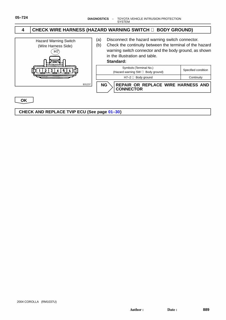
4 CHECK WIRE HARNESS (HAZARD WARNING SWITCH ⇔ BODY GROUND)
(a) Disconnect the hazard warning switch connector.(b) Check the continuity between the terminal of the hazard
warning switch connector and the body ground, as shownin the illustration and table.Standard:
Symbols (Terminal No.) (Hazard warning SW ⇔ Body ground)
Specified condition
H7–2 ⇔ Body ground Continuity
NG REPAIR OR REPLACE WIRE HARNESS ANDCONNECTOR
OK
CHECK AND REPLACE TVIP ECU (See page 01–30)

I24321 B59181
TVIP ECU
Engine Room J/B and R/B
SRLY21T3
Battery
FL MAIN
S8Starter Cut Relay
Instrument Panel J/B
ECM
Starter
STA9E4
B (M/T)B (A/T) B–R
B–W
B
2 1
34
W–B4IF
II17
A
IE
J6J/C
1S31S2
B–R
B–R2IA4
MAIN
2 1
B–R
J2G
J/C
II211
B (A/T)
B
B
B111A
B
11IL
1IM
2 1
53
ST Relay
3IM
J2G
–DIAGNOSTICS TOYOTA VEHICLE INTRUSION PROTECTIONSYSTEM
05–725
890Author�: Date�:
2004 COROLLA (RM1037U)
STARTER CUT RELAY CIRCUIT
CIRCUIT DESCRIPTIONWhen the TVIP system operates, the TVIP ECU controls the starter cut relay so that the relay should notbe turned on and consequently the starter can not crank the engine.
WIRING DIAGRAM
057S4–01

I24337
1
43 2
B52239
T3
SRLY (21)
TVIP ECU
05–726 –DIAGNOSTICS TOYOTA VEHICLE INTRUSION PROTECTIONSYSTEM
891Author�: Date�:
2004 COROLLA (RM1037U)
INSPECTION PROCEDURE
1 CHECK RELAY (Marking: STARTER CUT)
(a) Inspect the relay continuity, as shown in the illustrationand table.Standard:Terminal No. Condition Specified condition
1 ⇔ 2 Constant Continuity
3 ⇔ 4Apply B+ betweenterminals 1 and 2
Continuity
NG REPLACE RELAY
OK
2 CHECK TVIP ECU
(a) Disconnect the TVIP ECU connector.(b) Turn the ignition switch position to the START.(c) Measure the voltage between the terminal of the ECU
connector and the body ground, as shown in the illustra-tion and table.Standard:
Symbols (Terminal No.) Specified condition
SRLY (T3–21) ⇔ Body ground 10 – 14 V
NG REPAIR OR REPLACE WIRE HARNESS ANDCONNECTOR
OK
CHECK AND REPLACE TVIP ECU (See page 01–30)
I24320 B59182
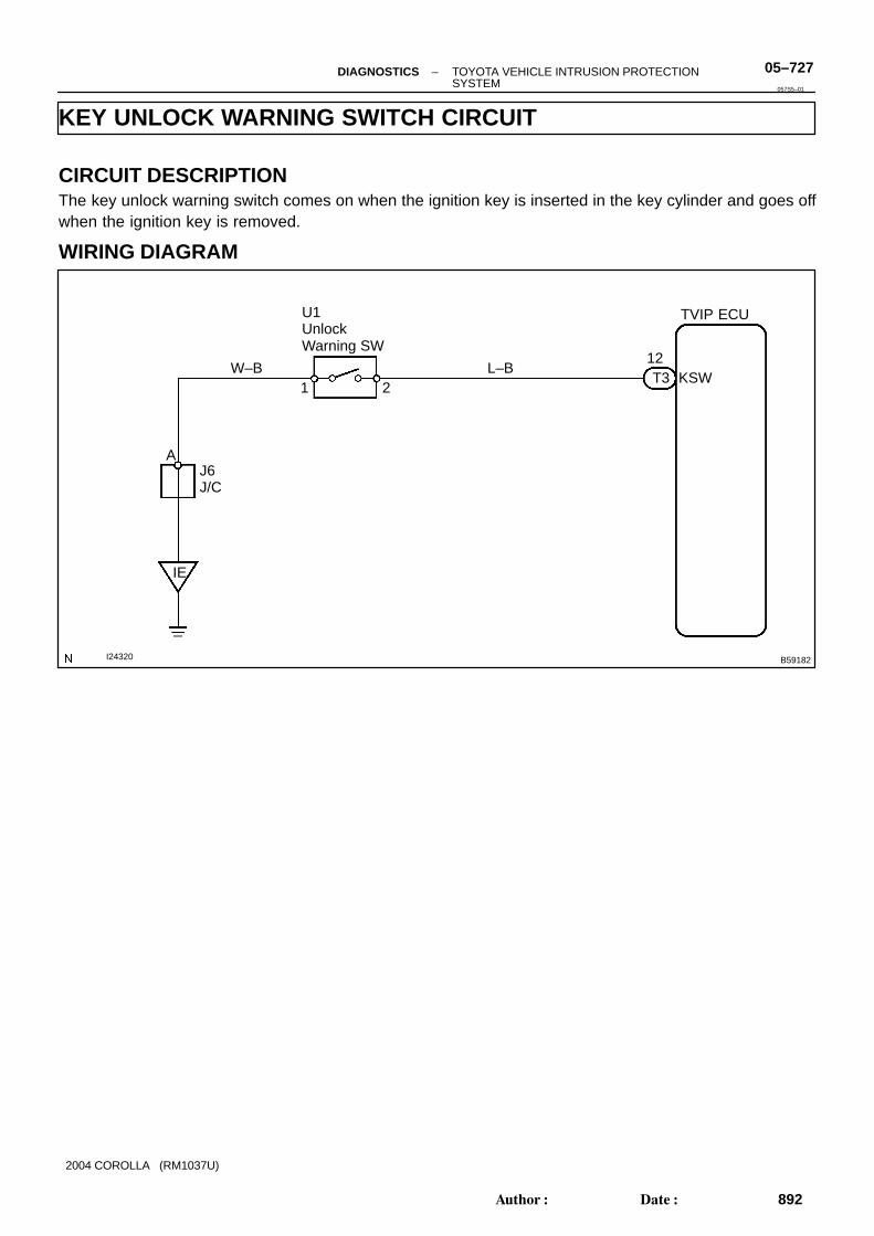
TVIP ECU
KSW1 2
12
U1UnlockWarning SW
J6J/C
A
IE
W–B L–BT3
–DIAGNOSTICS TOYOTA VEHICLE INTRUSION PROTECTIONSYSTEM
05–727
892Author�: Date�:
2004 COROLLA (RM1037U)
KEY UNLOCK WARNING SWITCH CIRCUIT
CIRCUIT DESCRIPTIONThe key unlock warning switch comes on when the ignition key is inserted in the key cylinder and goes offwhen the ignition key is removed.
WIRING DIAGRAM
057S5–01
B51903
Push
Free Unlock Warning SwitchUnlock Warning Switch
B59296
B52239
B59596
Unlock Warning Switch
TVIP ECU (Wire Harness Side)
T3
U1(Wire Harness Side)
1 2
KSW (12)
05–728 –DIAGNOSTICS TOYOTA VEHICLE INTRUSION PROTECTIONSYSTEM
893Author�: Date�:
2004 COROLLA (RM1037U)
INSPECTION PROCEDURE
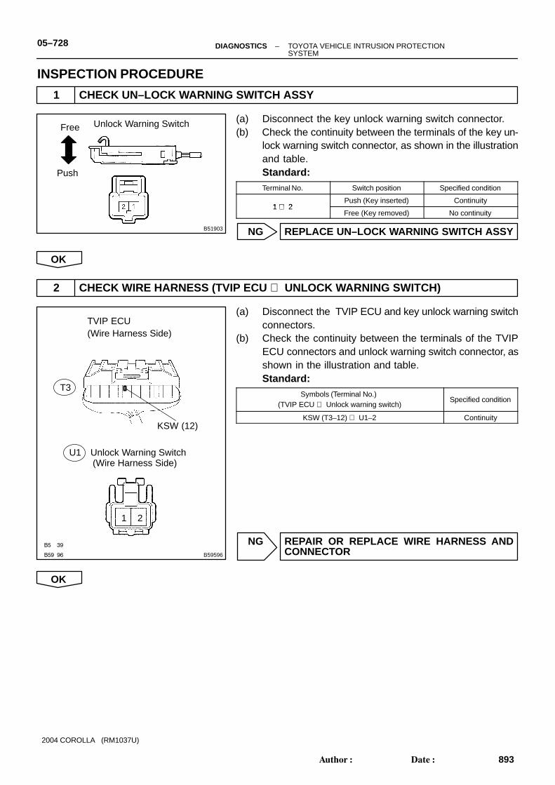
1 CHECK UN–LOCK WARNING SWITCH ASSY
(a) Disconnect the key unlock warning switch connector.(b) Check the continuity between the terminals of the key un-
lock warning switch connector, as shown in the illustrationand table.Standard:Terminal No. Switch position Specified condition
1 ⇔ 2Push (Key inserted) Continuity
1 ⇔ 2Free (Key removed) No continuity
NG REPLACE UN–LOCK WARNING SWITCH ASSY
OK
2 CHECK WIRE HARNESS (TVIP ECU ⇔ UNLOCK WARNING SWITCH)
(a) Disconnect the TVIP ECU and key unlock warning switchconnectors.
(b) Check the continuity between the terminals of the TVIPECU connectors and unlock warning switch connector, asshown in the illustration and table.Standard:
Symbols (Terminal No.) (TVIP ECU ⇔ Unlock warning switch)
Specified condition
KSW (T3–12) ⇔ U1–2 Continuity
NG REPAIR OR REPLACE WIRE HARNESS ANDCONNECTOR
OK

B59296
Unlock Warning SwitchU1(Wire Harness Side)
1 2
–DIAGNOSTICS TOYOTA VEHICLE INTRUSION PROTECTIONSYSTEM
05–729
894Author�: Date�:
2004 COROLLA (RM1037U)
3 CHECK WIRE HARNESS (KEY UNLOCK WARNING SWITCH ⇔ BODY GROUND)
(a) Disconnect the key unlock warning switch connector.(b) Check the continuity between the terminal of the key un-
lock warning switch connector and the body ground, asshown in the illustration and table.Standard:
Terminal No.(Key unlock warning SW ⇔ Body ground)
Specified condition
U1–1 ⇔ Body ground Continuity
NG REPAIR OR REPLACE WIRE HARNESS ANDCONNECTOR
OK
CHECK AND REPLACE TVIP ECU (See page 01–30)

I24322 B59183
TVIP ECU
S4Security Indicator(Glass Breakage Sensor)
G3 Glass Breakage Sensor ECU
Instrument Panel J/B
Engine Room J/B
I10 Ignition SW
Battery
FL MAIN ALT
AM1 IG1AM1
ECU–BR–B
IG1 RelayECU–IG1
IA
W
(Shielded)
SMIC
SMCE
3
4
IOUT11T3
L
B–W
MIC IOUT
GMIC GND
S+B TRIG
11D
1C
J6J/C
A
IE1
1A
2IF
12IF
1IH
9IF
4IF
1IB
1 2B–Y
W
W
W
W–B
B–W5
1 2
3
4
5
1
3
6
8
W
R–B
B1
1 2
W–B
W–B
J7J/C
A
IG
19
11 3A
3ARH J/B
Microphone
W–B
W
05–730 –DIAGNOSTICS TOYOTA VEHICLE INTRUSION PROTECTIONSYSTEM
895Author�: Date�:
2004 COROLLA (RM1037U)
GLASS BREAKAGE SENSOR CIRCUIT
CIRCUIT DESCRIPTIONThe microphone of the grass breakage sensor is built in the security indicator. When this microphone sensesbreakage of grass, the grass breakage sensor ECU sends the signal of this breakage to the TVIP ECU.
WIRING DIAGRAM
057S6–01

I24334
Connector connectedG3
B59576
TVIP ECU (Wire Harness Side)
Glass Breakage Sensor ECU(Wire Harness Side)
IOUT (3)
T3
G3
IOUT (11)
–DIAGNOSTICS TOYOTA VEHICLE INTRUSION PROTECTIONSYSTEM
05–731
896Author�: Date�:
2004 COROLLA (RM1037U)
INSPECTION PROCEDURE
1 CHECK SECURITY INDICATOR LIGHT
(a) Set the system in 30 seconds after filliping the security indicator to check if the alarm is triggered.
OK NO PROBLEM
NG
2 CHECK GLASS BREAKAGE SENSOR ECU (GLASS BREAKAGE SENSOR)
(a) Check the continuity and voltage of the glass breakagesensor ECU, as shown in the illustration and table.Standard:Terminal No. Condition Specified condition
G3–1 ⇔ Body ground Constant Battery voltage
G3–3 ⇔ Body ground Constant Pulse generation
G3–5 ⇔ Body ground Constant Continuity
G3–8 ⇔ Body ground Ignition switch ON Battery voltage
NG CHECK AND REPLACE GLASS BREAKAGESENSOR ECU (See page 01–30)
OK
3 CHECK WIRE HARNESS (TVIP ECU ⇔ GLASS BREAKAGE SENSOR ECU)
(a) Disconnect the TVIP ECU and glass breakage sensorECU connectors.
(b) Check the continuity and between the connectors on theharness side, as shown in the illustration and table.Standard:
Symbols (Terminal No.)(TVIP ECU ⇔ Sensor ECU)
Specified condition
IOUT (T3–11) ⇔ IOUT (G3–3) Continuity
NG REPAIR OR REPLACE WIRE HARNESS ANDCONNECTOR
OK

I24334
G3
Glass Breakage Sensor ECU(Wire Harness Side)
05–732 –DIAGNOSTICS TOYOTA VEHICLE INTRUSION PROTECTIONSYSTEM
897Author�: Date�:
2004 COROLLA (RM1037U)
4 CHECK WIRE HARNESS (GLASS BREAKAGE SENSOR ECU ⇔ BODY GROUND)
(a) Disconnect the glass breakage sensor ECU connector.(b) Check the continuity between the terminal of the glass
breakage sensor ECU connector and the body ground, asshown in the illustration and table.Standard:
Symbols (Terminal No.) (Glass breakage sensor ⇔ Body ground)
Specified condition
GND (G3–6) ⇔ Body ground Continuity
NG REPAIR OR REPLACE WIRE HARNESS ANDCONNECTOR
OK
CHECK AND REPLACE TVIP ECU (See page 01–30)

B59184
I11Integration Relay TVIP ECU
D5Door Courtesy SWFront RH
D4Door Courtesy SW Front LH
L4Luggage Compartment Light SW
D7Door Courtesy SWRear RH
D6Door Courtesy SW Rear LH
DMLP9
T3R–W
PCTY
LP
PRCTY
DCTY
13
3
6
5
R–W
R–W1
4IK
3IL
1ID
R
R–W
R–W1
R–W
J10J/C
AA
R–Y1
1R–B
15ID
14ID
CTY19T3
DSWD40T3
R–W
1 DSWL35T3
R–WID2
R–W 11
Instrument Panel J/B
–DIAGNOSTICS TOYOTA VEHICLE INTRUSION PROTECTIONSYSTEM
05–733
898Author�: Date�:
2004 COROLLA (RM1037U)
DOOR COURTESY SWITCH CIRCUIT
CIRCUIT DESCRIPTIONThe door courtesy switch turns ON when the door is opened and OFF when the door is closed.
WIRING DIAGRAM
057S7–01

B59818
Push
Free
B59191
B60033
B59599
(Wire Harness Side)
Integration Relay(Wire Harness Side)
I11
D5 Door Courtesy SW Front RH
05–734 –DIAGNOSTICS TOYOTA VEHICLE INTRUSION PROTECTIONSYSTEM
899Author�: Date�:
2004 COROLLA (RM1037U)
INSPECTION PROCEDURE
1 CHECK COURTESY LAMP SWITCH
(a) Check the courtesy switch, as shown in the illustrationand table.Standard:Terminal No. Switch position Specified condition
1 ⇔ Body groundPush Continuity
1 ⇔ Body groundFree No continuity
NG REPLACE COURTESY LAMP SWITCH
OK
2 CHECK WIRE HARNESS (INTEGRATION RELAY ⇔ DOOR COURTESY SW)
(a) Disconnect the integration relay and door courtesy con-nectors.
(b) Check the continuity between the terminals of the integra-tion relay and door courtesy switch connectors, as shownin the illustration and table.Standard:
Terminal No.(Integration relay ⇔ Door courtesy SW)
Specified condition
I11–13 ⇔ D5–1 Continuity

B59191
B59527
B59598
(Wire Harness Side)
Integration Relay (Instrument Panel J/B)(Wire Harness Side)
ID
D6
Door Courtesy SW Front LH
Door Courtesy SW Rear RH
Door Courtesy SW Rear LH
D4
D7
B59191
B52239
B59597
TVIP ECU (Wire Harness Side)
T3
L4
(Wire Harness Side)
Luggage Compartment Light SW
DSWL (35)
–DIAGNOSTICS TOYOTA VEHICLE INTRUSION PROTECTIONSYSTEM
05–735
900Author�: Date�:
2004 COROLLA (RM1037U)
(c) Disconnect the each door courtesy switch connectors.(d) Check the continuity between the terminals of the integra-
tion relay and door courtesy switch connectors, as shownin the illustration and table.Standard:
Terminal No.(Integration relay ⇔ Door courtesy SW)
Specified condition
ID–1 ⇔ D4–1
ID–15 ⇔ D7–1 Continuity
ID–14 ⇔ D6–1
y
NG REPAIR OR REPLACE WIRE HARNESS ANDCONNECTOR
OK
3 CHECK WIRE HARNESS (TVIP ECU ⇔ LUGGAGE COMPARTMENT LIGHT SW)
(a) Disconnect the TVIP ECU and luggage comportmentlight switch connectors.
(b) Check the continuity between the terminals of the TVIPECU and luggage compartment light switch connectors,as shown in the illustration and table.Standard:
Symbols (Terminal No.)(TVIP ECU ⇔ Luggage compartment light SW)
Specified condition
DSWL (T3–35) ⇔ L4–1 Continuity
NG REPAIR OR REPLACE WIRE HARNESS ANDCONNECTOR
OK
PROCEED TO NEXT CIRCUIT INSPECTION SHOWN ON PROBLEM SYMPTOMS TABLE (See page 01–30)

I24325 B59186
D8Door Key Lock and Unlock SW Front LHDoor Lock Motor Front LHDoor Unlock Detection SW Front LH
D9Door Key Lock and Unlock SW Front RHDoor Lock Motor Front RHDoor Unlock Detection SW Front RH
UL317T3
L2
W–BW–B
16T3
6IC1
J6J/C
W–B
J7J/C
A
IE IG
A
TVIP ECU
Unlock
Lock
L–Y
Center J/B
G24A
UL2
14A
18T3
G
L–Y10IC1
11IC1
G
G
G
GG
7
9
10
L–B
11IJ2
10IJ2L–B
6
5Unlock
Lock
8
1IJ2
W–B
05–738 –DIAGNOSTICS TOYOTA VEHICLE INTRUSION PROTECTIONSYSTEM
903Author�: Date�:
2004 COROLLA (RM1037U)
DOOR KEY LOCK AND UNLOCK SWITCH CIRCUIT
CIRCUIT DESCRIPTIONThe door key lock and unlock switch is built in the door lock motor.
WIRING DIAGRAM
057S9–01

431 2
65 87 9 10
B58512
B52239
B59591
Passenger’s Door Lock
TVIP ECU (Wire Harness Side)
T3
D8
D9(Wire Harness Side)
Driver’s Door Lock
L2 (16)UL3 (17)
UL2 (18)
431 2
65 87 9 10
B58512 B59773
Passenger’s Door Lock
D8
D9
(Wire Harness Side)
Driver’s Door Lock
–DIAGNOSTICS TOYOTA VEHICLE INTRUSION PROTECTIONSYSTEM
05–739
904Author�: Date�:
2004 COROLLA (RM1037U)
INSPECTION PROCEDURE
1 CHECK DOOR LOCK (See page 73–3)
NG REPLACE DOOR LOCK
OK
2 CHECK WIRE HARNESS (TVIP ECU ⇔ DOOR LOCK)
(a) Disconnect the TVIP ECU and door lock connectors.(b) Check the continuity between the terminals of the TVIP
ECU and door lock connectors, as shown in the illustra-tion and table.Standard:
Symbols (Terminal No.) (TVIP ECU ⇔ Door lock)
Specified condition
UL3 (T3–17) ⇔ D8–10
L2 (T3–16) ⇔ D8–9Continuity
L2 (T3–16) ⇔ D9–6Continuity
UL2 (T3–18) ⇔ D9–5
NG REPAIR OR REPLACE WIRE HARNESS ANDCONNECTOR
OK
3 CHECK WIRE HARNESS (DOOR LOCK ⇔ BODY GROUND)
(a) Disconnect the door lock connector.(b) Check the continuity between the terminal of the door lock
connector and the body ground, as shown in the illustra-tion and table.Standard:
Symbols (Terminal No.) (Door lock ⇔ Body ground)
Specified condition
D9–8 ⇔ Body groundContinuity
D8–7 ⇔ Body groundContinuity
NG REPAIR OR REPLACE WIRE HARNESS ANDCONNECTOR
OK
PROCEED TO NEXT CIRCUIT INSPECTION SHOWN ON PROBLEM SYMPTOMS TABLE (See page 05–707)

I24324 B59185
TVIP ECUD9Door Key Lock and Unlock SW Front RHDoor Lock Motor Front RHDoor Unlock Detection SW Front RH
D8Door Key Lock and Unlock SW Front LHDoor Lock Motor Front LHDoor Unlock Detection SW Front LH
Detection
Detection
LSWP38T3W–R
3IJ2
78
LSWD
1IJ2 W–BW–B
37T3
W3
IC16
IC1 W–B
J6J/C
W–B87
J7J/C
A
IEIG
A
W–R
W
05–736 –DIAGNOSTICS TOYOTA VEHICLE INTRUSION PROTECTIONSYSTEM
901Author�: Date�:
2004 COROLLA (RM1037U)
DOOR UNLOCK DETECTION SWITCH CIRCUIT
CIRCUIT DESCRIPTIONThe door unlock detection switch is built in the door lock motor assembly. This switch is ON when the doorlock knob is in the unlock position and OFF when the knob is in the lock position. The ECU detects the doorlock knob conditions in this circuit.
WIRING DIAGRAM
057S8–01

431 2
65 87 9 10
B58512
B52239
B59591
Passenger’s Door Lock
TVIP ECU (Wire Harness Side)
T3
D8
D9(Wire Harness Side)
Driver’s Door Lock
LSWP (38)
LSWD (37)
431 2
65 87 9 10
B58512 B59773
Passenger’s Door Lock
D8
D9
(Wire Harness Side)
Driver’s Door Lock
–DIAGNOSTICS TOYOTA VEHICLE INTRUSION PROTECTIONSYSTEM
05–737
902Author�: Date�:
2004 COROLLA (RM1037U)
INSPECTION PROCEDURE
1 CHECK DOOR LOCK (See page 73–3)
NG REPLACE DOOR LOCK
OK
2 CHECK WIRE HARNESS (TVIP ECU ⇔ DOOR LOCK)
(a) Disconnect the TVIP ECU and door lock connectors.(b) Check the continuity between the terminals of the TVIP
ECU and door lock connectors, as shown in the illustra-tion and table.Standard:
Symbols (Terminal No.) (TVIP ECU ⇔ Door lock)
Specified condition
LSWD (T3–37) ⇔ D8–8 Continuity
LSWP (T3–38) ⇔ D9–7 Continuity
NG REPAIR OR REPLACE WIRE HARNESS ANDCONNECTOR
OK
3 CHECK WIRE HARNESS (DOOR LOCK ⇔ BODY GROUND)
(a) Disconnect the door lock connector.(b) Check the continuity between the terminal of the door lock
connector and the body ground, as shown in the illustra-tion and table.Standard:
Terminal No. (Door lock ⇔ Body ground)
Specified condition
D9–8 ⇔ Body groundContinuity
D8–7 ⇔ Body groundContinuity
NG REPAIR OR REPLACE WIRE HARNESS ANDCONNECTOR
OK
PROCEED TO NEXT CIRCUIT INSPECTION SHOWN ON PROBLEM SYMPTOMS TABLE(See page 05–707)

I24326 B59563
TVIP ECUI11Integration Relay
TVSS26
W28T3 IRSG
05–740 –DIAGNOSTICS TOYOTA VEHICLE INTRUSION PROTECTIONSYSTEM
905Author�: Date�:
2004 COROLLA (RM1037U)
TVIP ECU COMMUNICATION CIRCUIT
CIRCUIT DESCRIPTIONThe wireless receiver receives a SET/UNSET signal for the TVIP system and sends the signal to the TVIPECU via the integration relay.
WIRING DIAGRAM
INSPECTION PROCEDURE
1 CHECK TVIP ECU
(a) Check that the operation of the TVIP function is normal.HINT:With this inspection, the TVIP ECU CPU can be diagnosed if it works normally or not.
NG CHECK AND REPLACE TVIP ECU (See page 01–30)
OK
057SA–01

B59601
Integration Relay
TVIP ECU (Wire Harness Side)
T3
I11
(Wire Harness Side)
IRSG (28)
TVSS (26)
–DIAGNOSTICS TOYOTA VEHICLE INTRUSION PROTECTIONSYSTEM
05–741
906Author�: Date�:
2004 COROLLA (RM1037U)
2 CHECK WIRE HARNESS (TVIP ECU ⇔ INTEGRATION RELAY)
(a) Disconnect the TVIP ECU and integration relay connec-tors.
(b) Check the continuity between the terminal of the TVIPECU connector and integration relay connectors, asshown in the illustration and table.Standard:
Symbols (Terminal No.) (TVIP ECU ⇔ Integration relay)
Specified condition
IRSG (T3–28) ⇔ TVSS (I11–26) Continuity
NG REPAIR OR REPLACE WIRE HARNESS ANDCONNECTOR
OK
CHECK AND REPLACE TVIP ECU (See page 01–30)