tpd section y - charging methodologies · 2018-11-27 · section y – charging methodologies part...
TRANSCRIPT
Joint Office of Gas Transporters --------------------------------------------------------------------------------------- Uniform Network Code – Transportation Principal Document Section Y
© 2005 all rights reserved TPDY - 1 Version 4.56 18 December 2014
UNIFORM NETWORK CODE – TRANSPORTATION PRINCIPAL DOCUMENT
SECTION Y – CHARGING METHODOLOGIES
PART A – NTS CHARGING METHODOLOGIES
1. The Gas Transmission Transportation Charging Methodology
CHAPTER 1: PRINCIPLES
1.1 Price Control Formulae
The transportation price control treats the NTS Transportation Owner (TO) and the NTS System Operator (SO) separately. The separate price controls and incentives determine the maximum revenue that National Grid may derive from each in a formula year, 1 April to 31 March.
The Maximum Allowed Revenue under the transportation controls and incentives is determined by a number of factors including:
• the volume of NTS entry and exit capacity made available;
• National Grid’s performance under the various SO incentive schemes, covering a range of activities;
• the indexation factor - under the TO formula allowed revenue is adjusted each year by a factor equal to the rate of inflation, measured on a prescribed historical basis by reference to the Retail Price Index (RPI); and
• any under or over-recovery brought forward under each control from the previous formula year (expressed by means of a separate “K” factor within each control).
1.2 Structure of NTS Transportation Charges
Charges are set separately for those activities related to the Transportation Owner (TO) and to the System Operator (SO).
The maximum revenue to be collected from the NTS TO and NTS SO charges is determined by the TO and SO price controls, as described in Section 1.1 above. The NTS TO allowed revenue is collected by entry and exit capacity charges, with a TO commodity charge levied on entry flows where entry auction revenue is forecast to be under-recovered, and a TO Commodity charge levied on exit flows where revenue from exit capacity bookings is forecast to be under recovered. The NTS SO allowed revenue is collected largely by means of a commodity charge levied on entry and exit flows.
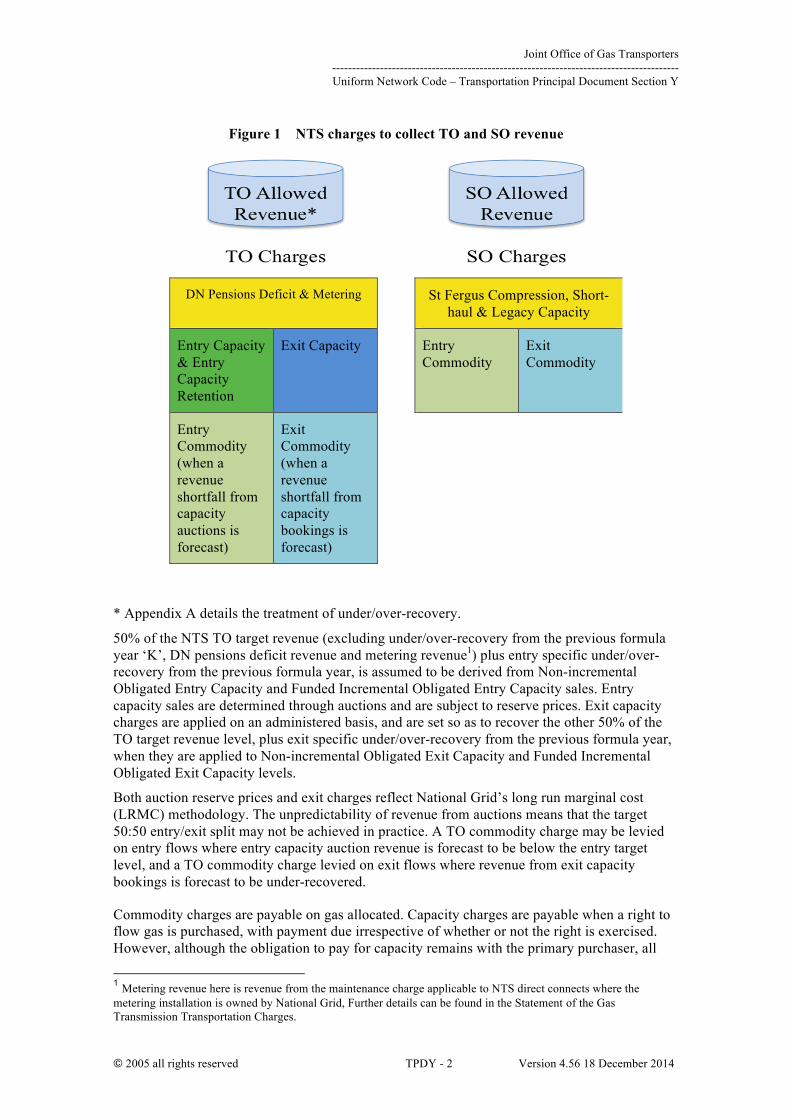
Figure 1 below shows the relationship between the TO and SO allowed revenue and NTS charges.
Joint Office of Gas Transporters --------------------------------------------------------------------------------------- Uniform Network Code – Transportation Principal Document Section Y
© 2005 all rights reserved TPDY - 2 Version 4.56 18 December 2014
Figure 1 NTS charges to collect TO and SO revenue
DN Pensions Deficit & Metering St Fergus Compression, Short-haul & Legacy Capacity
Entry Capacity & Entry Capacity Retention
Exit Capacity Entry Commodity
Exit Commodity
Entry Commodity (when a revenue shortfall from capacity auctions is forecast)
Exit Commodity (when a revenue shortfall from capacity bookings is forecast)
* Appendix A details the treatment of under/over-recovery.
50% of the NTS TO target revenue (excluding under/over-recovery from the previous formula year ‘K’, DN pensions deficit revenue and metering revenue1) plus entry specific under/over-recovery from the previous formula year, is assumed to be derived from Non-incremental Obligated Entry Capacity and Funded Incremental Obligated Entry Capacity sales. Entry capacity sales are determined through auctions and are subject to reserve prices. Exit capacity charges are applied on an administered basis, and are set so as to recover the other 50% of the TO target revenue level, plus exit specific under/over-recovery from the previous formula year, when they are applied to Non-incremental Obligated Exit Capacity and Funded Incremental Obligated Exit Capacity levels.
Both auction reserve prices and exit charges reflect National Grid’s long run marginal cost (LRMC) methodology. The unpredictability of revenue from auctions means that the target 50:50 entry/exit split may not be achieved in practice. A TO commodity charge may be levied on entry flows where entry capacity auction revenue is forecast to be below the entry target level, and a TO commodity charge levied on exit flows where revenue from exit capacity bookings is forecast to be under-recovered.
Commodity charges are payable on gas allocated. Capacity charges are payable when a right to flow gas is purchased, with payment due irrespective of whether or not the right is exercised. However, although the obligation to pay for capacity remains with the primary purchaser, all
1 Metering revenue here is revenue from the maintenance charge applicable to NTS direct connects where the metering installation is owned by National Grid, Further details can be found in the Statement of the Gas Transmission Transportation Charges.

Joint Office of Gas Transporters --------------------------------------------------------------------------------------- Uniform Network Code – Transportation Principal Document Section Y
© 2005 all rights reserved TPDY - 3 Version 4.56 18 December 2014
types of entry capacity can be traded between Shippers, such as Monthly System Entry Capacity (MSEC).
Having established, by the above methods, the target revenue to be derived from each main category of charge, the next stage is to set the charges2 within each of these charge categories. The methodologies used to do this are described in the appropriate sections below.
2 All charge rates are rounded to 4 decimal places.

Joint Office of Gas Transporters --------------------------------------------------------------------------------------- Uniform Network Code – Transportation Principal Document Section Y
© 2005 all rights reserved TPDY - 4 Version 4.56 18 December 2014
CHAPTER 2: CAPACITY CHARGES
NTS capacity charges consist of charges for exit, entry and credits payable for constrained LNG.
The NTS Transportation Model is used in deriving the NTS capacity charges. The details of the Transport model and the Tariff Model which make up the charging model are available in section 2.5 below.
2.1 System Exit Firm Capacity
The terms on which Enduring Annual, Annual and Daily firm NTS Exit (Flat) Capacity is sold are set out in the UNC Transportation Principal Document Section B. Charges reflect the estimated long run marginal cost (LRMC) of reinforcing the system to transport additional gas between entry and exit points. The calculations are described in more detail below.
2.2 System Exit Off-peak Capacity
The terms of which Off-peak NTS Exit (Flat) Capacity is sold are set out in the UNC Transportation Principal Document Section B. Off-peak capacity is auctioned on a daily day-ahead basis with a zero reserve price.
2.3 System Entry Capacity
System Entry Capacity allocated by means of five principle related auction mechanisms.
• Quarterly (firm) System Entry Capacity (QSEC)
• Monthly (firm) System Entry Capacity (MSEC)
• Rolling Monthly (firm) Transfer and Trade System Entry Capacity (RMTTSEC)
• Daily (firm) System Entry Capacity (DSEC)
• Daily Interruptible System Entry Capacity (DISEC)
The reserve prices applicable to each type of auction are set out in section 2.3.1 below.
2.3.1 Reserve Prices in System Entry Capacity Auctions
System entry capacity is allocated by means of auctions as described in the UNC and outlined in Section 2.3 above. This approach includes various reserve prices below which bids will not be accepted.
QSEC reserve prices for obligated entry capacity are calculated each year through using the NTS Transportation Model as described in 2.5 below. QSEC step prices for release of additional (incremental) capacity are calculated with reference to the applicable reserve price and in accordance with the methodology for the determination of incremental step prices as set out in National Grid’s Entry Capacity Release (ECR) methodology statement.
MSEC reserve prices are equal to the obligated capacity price for capacity offered in the auction of QSEC capacity.
Reserve prices are calculated by applying the following discounts to the MSEC obligated capacity prices:
• Day Ahead Daily System Entry Capacity (DADSEC); 33.3%
• Within Day Daily System Entry Capacity (WDDSEC); 100%
• Daily Interruptible System Entry Capacity (DISEC); 100%
Discretionary Release System Entry Capacity (DRSEC) released via auction is subject to the prevailing MSEC reserve price.

Joint Office of Gas Transporters --------------------------------------------------------------------------------------- Uniform Network Code – Transportation Principal Document Section Y
© 2005 all rights reserved TPDY - 5 Version 4.56 18 December 2014
2.3.2 Entry Capacity Buy-Back Offset Mechanism
The entry capacity buy-back offset mechanism can be triggered as the initial means of managing excess entry TO revenue to avoid over-recovery.
The level of this excess revenue is available to be used to offset the costs of entry capacity buy-back that would otherwise be borne by shippers through the capacity neutrality mechanism. This is achieved by way of a credit in their entry capacity charges for each month (by the lower of the excess accrued in the financial year to date and monthly buy-back cost). The credit per shipper is paid on the same capacity holding on which neutrality is charged i.e. all firm capacity holdings. Any excess amount (of over-recovery) remaining for any month is carried forward to the next month.
Trigger
Ø The mechanism would be triggered if the revenue implied by NTS Entry Capacity auctions breached either the Licence obligation not to exceed the maximum NTS transportation owner revenue (MRt) by more than 4% in any formula year or not to exceed the maximum NTS transportation owner revenue by more than 6% over any two formula years
Ø The process would be triggered at any point during the formula year based on the outcome of any NTS Entry Capacity auction that represented a TO revenue stream
Mechanism
Ø The over-recovery amount will be calculated as the difference between TO Entry Revenue and TO Entry Target Revenue.
Ø The full over-recovery amount would be available in relation to the first month for which the mechanism was triggered
Ø Any residual over-recovery at the end of the month would be rolled forward to the next month.
Ø Any residual over-recovery at the end of the formula year would be used to offset buy-back costs in those months within the formula period when buy-back costs had occurred and no credit had been paid or where the credit was less than the buy-back cost (un-credited buy-back costs)
o Where the residual over-recovery is less than the aggregate un-credited buy-back costs,
§ Credits would be calculated for each month in proportion to the un-credited buy-back costs in each month.
o Where the residual over-recovery is equal to or greater than the aggregate un-credited buy-back costs,
§ Credits would be calculated for each month equal to the un-credited buy-back costs in each month.
o Credits in relation to un-credited buy-back costs in each month would be apportioned to each Shipper on the basis of its original capacity holdings for that month
Ø The credit would offset buy-back costs and hence daily capacity and over-run revenue could represent an additional credit through capacity neutrality
2.4 Constrained LNG (CLNG)
The credit is related to the peak booking by National Grid of CLNG; is based on the Long Run
Joint Office of Gas Transporters --------------------------------------------------------------------------------------- Uniform Network Code – Transportation Principal Document Section Y
© 2005 all rights reserved TPDY - 6 Version 4.56 18 December 2014
Marginal Cost (LRMC) at the CLNG node (ie the LRMC between the National Balancing Point (NBP) and the CLNG site.
The credit is made available via National Grid’s LNG Storage business unit to those shippers booking the bundled storage service as offered via auction. Further details are available on request from National Grid’s LNG Storage business unit.
2.5 Derivation of NTS Capacity Charges
The NTS Transportation Model comprises:
The Transport Model that calculates the Long Run Marginal Costs (LRMCs) of transporting gas from each entry point (for the purposes of setting NTS Entry Capacity Prices) to a “reference node” and from the “reference node” to each relevant offtake point.
The Tariff Model that adjusts the LRMCs to either maintain an equal split of revenue between Entry and Exit users (where entry prices are used to set auction reserve prices) or to recover a target level of revenue (where exit prices are set as administered rates).
Prices for each Gas Year are calculated using the relevant year’s 1-in-20 peak base case supply and demand data and network model (e.g. if setting exit capacity prices for Gas Year 2010/11, the base case supply/demand forecast for 2010/11 and the base network model are used).
Obligated Entry Capacity Reserve Prices are set by adjusting supply flows in the base case data to reflect the obligated flow at each NTS Entry Point.
2.5.1 The Transport Model
Model Input Data
(a) The Transport Model calculates the marginal costs of investment required in the National Transmission System as a consequence of an increase in demand for gas or supply of gas at each System Point or node on the National Transmission System. Such calculation is based upon analysis of peak conditions on the National Transmission System and the costs of investment which are expressed in £/GWhkm. Where there is an increase in demand for gas or supply of gas at a System Point the marginal changes in flow distances (measured in GWhkm) for a small energy injection to the system (measured in GWh) shall be estimated initially by reference to the increases or decreases in units of kilometres of the National Transmission System.
(b) The Transport Model requires a set of inputs which are consistent with the costs incurred by National Grid NTS in making NTS Exit (Flat) Capacity available on the National Transmission System:
(i) Nodal supply and demand data (GWh)
(A) Demand data shall be derived in relation to each NTS Exit Point as the lesser of:
(1) the National Grid NTS forecast undiversified 1-in-20 peak day demand at the relevant NTS Exit Point, provided that:
(aa) for any NTS Connected Offtake System which is a Storage Facility or a pipeline interconnector and which has a physical entry capability, demand at the relevant NTS Connected System Exit Point shall be deemed to be zero;
(bb) for NTS/LDZ Offtakes, the National Grid NTS forecast undiversified 1-in-20 peak day demand in the relevant LDZ shall be prorated between the relevant NTS/LDZ

Joint Office of Gas Transporters --------------------------------------------------------------------------------------- Uniform Network Code – Transportation Principal Document Section Y
© 2005 all rights reserved TPDY - 7 Version 4.56 18 December 2014
Offtakes on the basis of the amount of NTS Exit (Flat) Capacity registered at each of the relevant NTS/LDZ Offtakes;
For the purposes of this paragraph, “National Grid NTS forecast undiversified 1-in-20 peak day demand” means the 1-in-20 peak day demand for the National Transmission System that is derived from the summation of the forecast peak demands and load duration curves for each NTS Supply Point, NTS CSEP and NTS/LDZ Offtake; and
(2) the aggregate of the Baseline NTS Exit (Flat) Capacity and incremental NTS Exit (Flat) Capacity in respect of the relevant NTS Exit Point,
provided that paragraph (2) above shall be ignored for the purposes of setting or determining any indicative NTS Exit (Flat) Capacity Charges;
(B) Aggregate System Entry Point supplies
(ii) Transmission pipelines between each node (measured in km) and calculated by reference to;
(1) Existing pipelines
(2) New pipelines expected to be operational on or before the start of the Gas Year under analysis
(iii) Identification of a reference node.
Model Inputs
(c) The nodal supply data for the Transport Model shall be derived from the supply/demand data set out in the most recent Ten Year Statement3 for each Gas Year for which prices are being determined. The aggregate supply flow shall be adjusted to ensure that the values for supply and demand are equal. This adjustment shall be carried out by reducing supplies in the following order to the point at which supplies equal the forecast demand:
(i) short range Storage Facilities;
(ii) mid range Storage Facilities;
(iii) LNG Importation Facilities;
(iv) long range Storage Facilities;
(v) pipeline interconnectors; and
(vi) beach terminals.
The supply figures for Individual System Entry Points at Storage Facilities and/or pipeline interconnectors may be set at a level that is less than or equal to the expected entry point capability.
(d) Nodal demand data for the Transport Model shall be derived from a range of different data sources as more particularly described in paragraph 2.5.1(b)(i).
(e) National Transmission System network data for the charging year will be based on data taken from National Grid NTS’s most recent Ten Year Statement.
3 See Appendix C for definitions.

Joint Office of Gas Transporters --------------------------------------------------------------------------------------- Uniform Network Code – Transportation Principal Document Section Y
© 2005 all rights reserved TPDY - 8 Version 4.56 18 December 2014
Model Outputs
The Transport Model is an optimisation model that calculates the minimum total network flow distance (in GWhkm) given a set of supply and demand flows i.e. it takes the inputs described above and uses a transport algorithm to derive the pattern of balanced network flows that minimises distances travelled by these flows from a supply node or to a demand node, assuming every network section has sufficient capacity.
The marginal cost values are expressed solely in km as they are flow gradients i.e. they represent the sensitivity of the total network flow distance value to a change in supply or demand at any node.
Sum of flow times distance (GWh x km) divided by Change in Nodal flow (GWh) equals marginal cost (km)
The model computes a marginal cost for supply at each node (which may be positive or negative in relation to the reference node). The marginal cost for demand at each node is then the equal and opposite of the nodal marginal cost for supply. A negative marginal cost represents a marginal benefit or avoided cost at that point.
2.5.2 The Tariff Model
The Initial Nodal Marginal Distances
The key inputs to the Tariff Model are the marginal costs of supply and the marginal costs of demand calculated from the transport model. These are used to set the Initial Nodal Marginal Distances (InitialNMkm):
and
Where
InitialNMkmSi = Initial nodal marginal distance for supply i (km)
InitialNMkmDj = Initial nodal marginal distance for demand j (km)
LRMCSi = Long run marginal cost of flow to reference node from supply i (km)
LRMCDji = Long run marginal cost of flow to reference node from demand j (km)
The Initial Nodal Marginal Distances are adjusted to either maintain an equal split of revenue between Entry and Exit users where prices are used to set auction reserve prices, or to recover a target level of revenue, where prices are set at administered rates. The adjustments made for entry and exit capacity charges are described in detail later in this document.
The adjusted marginal distances are converted into unit costs (£/GWh) by multiplying by the expansion constant (see below). These unit costs can then be converted into daily prices by applying the annuitisation factor4 (which has been calculated assuming a 45 year asset life, an allowed rate of return of 6.25% on capital expenditure and 1% operating expenditure allowance) and then dividing by the number of days in the year. For entry prices, an adjustment to reflect the calorific value at the ASEP is also applied.
4 The annuitisation factor is no longer contained as a separate term in the Licence but is implicit within the revenue drivers. However, a factor of 0.10272 was agreed with the Authority as quoted in paragraph 1.82 of the Transmission Price Control Review: Final Proposals, Appendices, Ofgem, 4th December 2006, Ref: 206/06b.

Joint Office of Gas Transporters --------------------------------------------------------------------------------------- Uniform Network Code – Transportation Principal Document Section Y
© 2005 all rights reserved TPDY - 9 Version 4.56 18 December 2014
The Expansion Constant
The expansion constant, expressed in £/GWhkm, represents the capital cost of the transmission infrastructure investment required to transport 1 GWh over 1 km. Its magnitude is derived from the projected cost of an 85bar pipeline and compression for a 100km NTS network section. The 100km distance was selected as this represents the typical compressor spacing on the NTS. The expansion constant derived in gas year N will be used to derive all indicative and actual prices for gas year N+4 e.g. the expansion constant derived in 2009 will be used to set all indicative and actual prices for gas year starting 1st October 2012. For information on the expansion constant(s) used for each gas year, please refer to National Grid’s Statement of Gas Transportation Charges.
Calculated from first principles, the steps taken to derive the expansion constant are as follows:
a) National Grid determines the projected £/GWhkm cost of expansion of 85bar gauge pressure pipelines and compression facilities, based on manufacturers’ budgetary prices and historical costs inflated to present values.
b) An average expansion constant is calculated from the largest three pipeline diameter/compressor sections D1, D2, D3 (network sections n = 1, 2, and 3). The selection of expansion constants calculated from these three network sections is based on recent and expected future projects on the transmission system. The pipe diameters used are: D 1 = 900 mm D 2 = 1050 mm D 3 = 1200 mm
c) The maximum daily flow that can be facilitated through each of the three network sections is calculated. This is based on assumptions of an 85barg inlet pressure and a minimum outlet pressure of 38barg and is calculated from the Panhandle A pipe flow equation (a standard flow equation used within the gas industry).
Where
Qn = Flow for network section n (mscmd)
Kflow = Constant (0.0045965)
Tstd = Standard temperature (291.4°K)
Pstd = Standard pressure (1.01325 bara)
Dn = Diameter for network section n (mm)
P1 = Pipe absolute inlet pressure (86.01325 bara = 85 barg)
P2,n = Pipe absolute outlet pressure for network section n (bara greater than or = 38 barg)

Joint Office of Gas Transporters --------------------------------------------------------------------------------------- Uniform Network Code – Transportation Principal Document Section Y
© 2005 all rights reserved TPDY - 10 Version 4.56 18 December 2014
G = Gas specific gravity (0.6)
Tav = Pipeline average temperature (285.4°K)
L = Pipe length (100 km)
Zav = Average gas compressibility (0.85)
d) The maximum daily energy flow is calculated from the volumetric flow using a standard planning CV of 39 MJ/m3 and the planning flow margin of 5%.
Where
Capacityn = Daily capacity for network section n (GWh)
Qn = Flow for network section n (mscmd)
CV = Calorific Value (39 MJ/m3)
FM = Flow margin (5%)
3.6 = Converts 106 MJ to GWh
e) The compressor power requirement to recompress back to 85 barg is calculated from the flow and the inlet and outlet pressures. The inlet pressure for the compressor is the outlet pressure of the pipe section for each pipe diameter D.
Where
Powern = Compressor power for network section n (MW)
Pin,n = Compressor absolute inlet pressure for network section n(bara)
Pout = Compressor absolute outlet pressure (86.10325 bara)
Kpower = Constant (0.0040639)
Zav = Compressibility (0.85)
Tav = Average gas temperature (285.4°K)
Qn = Flow for network section n (mscmd)
= Isentropic index (1.363)

Joint Office of Gas Transporters --------------------------------------------------------------------------------------- Uniform Network Code – Transportation Principal Document Section Y
© 2005 all rights reserved TPDY - 11 Version 4.56 18 December 2014
η = Compressor adiabatic efficiency (80%)
FM = Flow margin (5%)
f) The capital cost of the pipe for each network section is calculated from the pipe cost equation, the pipe diameter and the pipe length of 100km.
Pipe_Costn = L x (D n x Pipecost_diameter_factor + Pipecost_constant_factor)
Where
Pipe_Costn = Capital cost for pipe in network section n (£m)
L = Length (100 km)
D n = Diameter for network section n (mm)
Pipecost_diameter_factor = Capital cost factor (£m/km/mm)
Pipecost_constant_factor = Capital cost factor (£m/km)
g) The capital cost of recompression from the minimum pressure up to 85barg is calculated from the compressor power requirements
Compressor_Costn = Powern x Power_Unit_Cost
Where
Compressor_Costn = Capital cost for compression in network section n (£m)
Powern = Compression power for network section n (MW)
Power_Unit_Cost = Unit cost for additional power at existing stations (£m/MW)
h) An allowance for engineering and project planning costs is included at 15%.
Project_Costn = Project_Factor * (Pipe_Costn + Compressor_Costn )
Where
Project_Costn = Project costs for network section n (£m)
Project_Factor = 15%
Pipe_Costn = Capital cost for pipe in network section n (£m)
Compressor_Costn = Capital cost for compression in network section n (£m)
i) The total cost is the pipe cost plus the compressor cost plus the project costs (£)
Total_Costn = Pipe_Costn + Compressor_Costn + Project_Costn
Where
Joint Office of Gas Transporters --------------------------------------------------------------------------------------- Uniform Network Code – Transportation Principal Document Section Y
© 2005 all rights reserved TPDY - 12 Version 4.56 18 December 2014
Total_Costn = Total cost for network section n (£m)
Pipe_Costn = Capital cost for pipe in network section n (£m)
Compressor_Costn = Capital cost for compression in network section n (£m)
j) The unit cost is the total cost divided by the maximum energy flow (£m/GWh)
Unit_Costn = Total_Costn / Capacityn
Where
Unit_Costn = Total unit cost for network section n (£m/GWh)
Total_Costn = Total cost for network section n (£m)
Capacityn = Daily capacity for network section n (GWh)
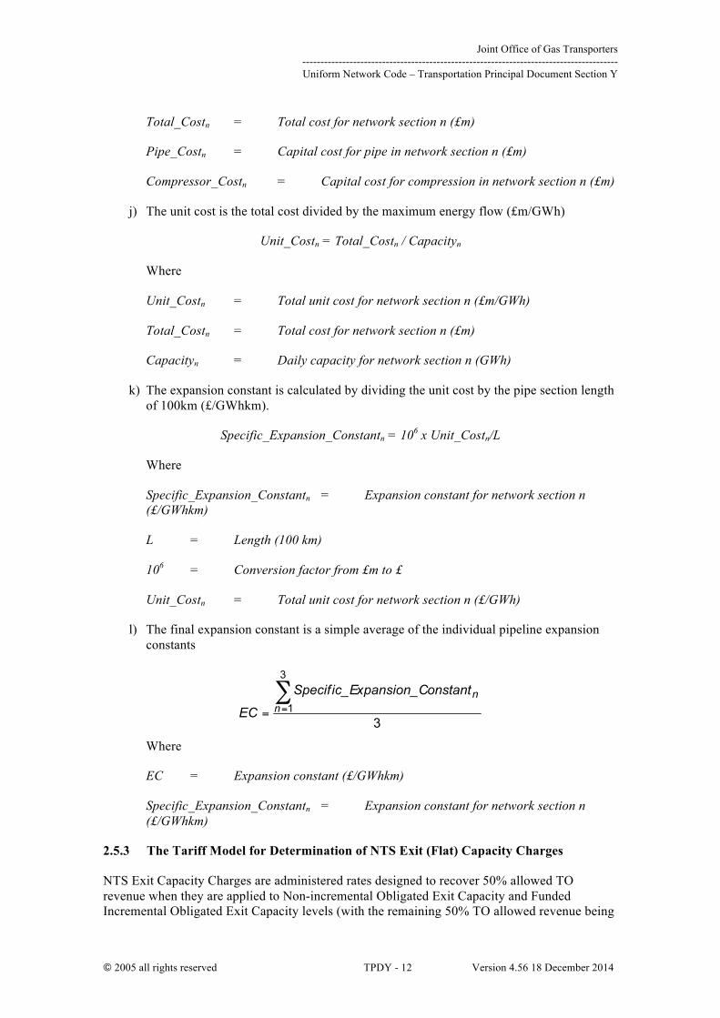
k) The expansion constant is calculated by dividing the unit cost by the pipe section length of 100km (£/GWhkm).
Specific_Expansion_Constantn = 106 x Unit_Costn/L
Where
Specific_Expansion_Constantn = Expansion constant for network section n (£/GWhkm)
L = Length (100 km)
106 = Conversion factor from £m to £
Unit_Costn = Total unit cost for network section n (£/GWh)
l) The final expansion constant is a simple average of the individual pipeline expansion constants
Where
EC = Expansion constant (£/GWhkm)
Specific_Expansion_Constantn = Expansion constant for network section n (£/GWhkm)
2.5.3 The Tariff Model for Determination of NTS Exit (Flat) Capacity Charges
NTS Exit Capacity Charges are administered rates designed to recover 50% allowed TO revenue when they are applied to Non-incremental Obligated Exit Capacity and Funded Incremental Obligated Exit Capacity levels (with the remaining 50% TO allowed revenue being
Joint Office of Gas Transporters --------------------------------------------------------------------------------------- Uniform Network Code – Transportation Principal Document Section Y
© 2005 all rights reserved TPDY - 13 Version 4.56 18 December 2014
recovered through Entry charges). The process for calculating NTS Exit Capacity Charges is described below.
Supply/Demand Scenario and Network Model
Prices for each Gas Year are calculated using the relevant year’s supply and demand data, and network model (e.g. if setting exit capacity prices for Gas Year 2012/13, the base case supply/demand forecast for 2012/13 and the base network model for 2012/13 are used).
TO Revenue Recovery Adjustment
The total TO revenue to be recovered through NTS Exit (Flat) Capacity and Commodity Charges is determined each year with reference to the Price Control formulae stated in the Licence. A description of the principal formulae can be found in Appendix A.
In any given year t, a target revenue figure for Exit Capacity Charges (TORExCt) is set. An adjustment is made to compensate for any exit specific under or over-recovery from the relevant year (Kt). For further information, please refer to Special Condition 2A and 5G of the Licence, and Appendix A of this document.
Revenue from Legacy Incremental Exit Capacity5 (LIExCt6) is treated as SO revenue within the Price Control formulae stated in the Licence (SORExCt). For further information, please refer to Special Condition 3A of the Licence.
From 01 April 2013, revenue from Non-incremental Obligated Exit Capacity and Funded Incremental Obligated Exit Capacity (whether satisfied through substitution or investment) is treated as TO revenue within the Price Control formulae stated in Licence (TORExCt)7. For further information, please refer to Special Condition 2A of National Grid NTS’s Transporter’s Licence.
NTS Exit (Flat) Capacity prices are set through the Transportation Model such that target NTS Exit (Flat) Capacity revenue equals Non-incremental Obligated Exit Capacity and Funded Incremental Obligated Exit (TO) Capacity revenue, i.e. Non-incremental Obligated Exit Capacity and Funded Incremental Obligated Exit Capacity levels multiplied by the relevant offtake price represents 50% of TO remaining allowed revenue after deducting non-capacity TO charge revenues (including DN pensions charge revenue). Any shortfall in (TO) NTS Exit (Flat) Capacity revenue will be collected through the (TO) NTS Exit (Flat) Commodity charge.
A single additive constant Revenue Adjustment Factor (RAF) is calculated using Microsoft Excel Solver which, when added to the Initial Nodal Marginal Distance at each demand, gives a revised marginal distance for each demand, such that the total revenue to be recovered from NTS Exit (Flat) Capacity charges in relation to Non-incremental Obligated Exit Capacity and Funded Incremental Obligated Exit Capacity equals the target revenue (i.e. TORExCt). The SO revenue (i.e. LIExCt) can be calculated from the prices where Legacy Incremental Exit Capacity is released.
The calculation simultaneously removes the negative marginal distances by collaring the revenue to that level implied by the minimum price of 0.0001 p/kWh. 5 Please refer to Licence Special Condition 1A. Definitions. 6 Whilst Legacy Incremental Exit Capacity is defined in the Licence, the term “LIExCt” is not used. “LIExCt” is used for the purposes of the NTS Charging Methodology to represent the revenue from Legacy Incremental Exit Capacity, and contributes to the SORExCt revenue term as defined in the Licence. 7 For Exit Capacity charge setting purposes it is assumed that all Non-incremental Obligated Exit Capacity is sold ahead of the day.

Joint Office of Gas Transporters --------------------------------------------------------------------------------------- Uniform Network Code – Transportation Principal Document Section Y
© 2005 all rights reserved TPDY - 14 Version 4.56 18 December 2014
TORExCt =
€
t,DjExitRev( )Dj=1
nD
∑
LIExCt =
€
t,Dj,incExitRev( )Dj=1
nD
∑
Where
ExitRevt,Dj = Non-incremental Obligated Exit Capacity and Funded Incremental Obligated Exit Capacity revenue from demand j (£m/year)
ExitRevt,Dj,inc = Legacy Incremental Exit Capacity revenue from demand j (£m/year)
TORExCt = Non-incremental Obligated Exit Capacity and Funded Incremental Obligated Exit Capacity revenue for year t (£m)
LIExCt = Legacy Incremental Exit Capacity revenue for year t (£m)
InitialNMkmDj = Initial nodal marginal distance for demand j (km)
RAF = Revenue adjustment factor (km)
ExitCapDj = Nodal Non-incremental Obligated Exit Capacity8 and Funded Incremental Obligated Exit Capacity for demand j (GWh/day)
ExitCapDj, inc = Nodal Legacy Incremental Exit Capacity9 for demand j (GWh/day)
AnF = Licence implied annuitisation factor (per year)
EC = Expansion constant (£/GWhkm)
0.0001 = Minimum price (p/kWh)
365 = Conversion factor from per day to per year
100 = Conversion factor from p to £
106 = Conversion factor from £ to £m
nD = Number of demand charging points
Nodal Exit Capacity Charges 8 Please refer to Special Condition 5G.30 of the Licence. 9 Please refer to Special Condition 5G.33 of the Licence.
Joint Office of Gas Transporters --------------------------------------------------------------------------------------- Uniform Network Code – Transportation Principal Document Section Y
© 2005 all rights reserved TPDY - 15 Version 4.56 18 December 2014
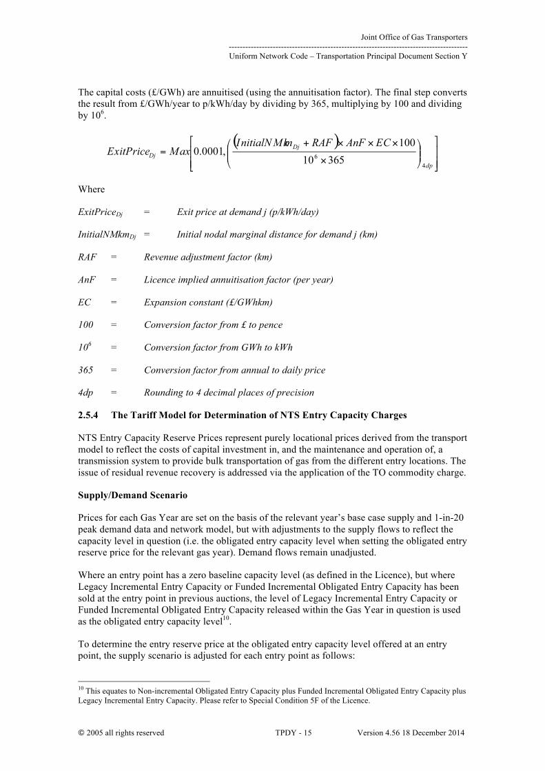
The capital costs (£/GWh) are annuitised (using the annuitisation factor). The final step converts the result from £/GWh/year to p/kWh/day by dividing by 365, multiplying by 100 and dividing by 106.
Where
ExitPriceDj = Exit price at demand j (p/kWh/day)
InitialNMkmDj = Initial nodal marginal distance for demand j (km)
RAF = Revenue adjustment factor (km)
AnF = Licence implied annuitisation factor (per year)
EC = Expansion constant (£/GWhkm)
100 = Conversion factor from £ to pence
106 = Conversion factor from GWh to kWh
365 = Conversion factor from annual to daily price
4dp = Rounding to 4 decimal places of precision
2.5.4 The Tariff Model for Determination of NTS Entry Capacity Charges
NTS Entry Capacity Reserve Prices represent purely locational prices derived from the transport model to reflect the costs of capital investment in, and the maintenance and operation of, a transmission system to provide bulk transportation of gas from the different entry locations. The issue of residual revenue recovery is addressed via the application of the TO commodity charge.
Supply/Demand Scenario
Prices for each Gas Year are set on the basis of the relevant year’s base case supply and 1-in-20 peak demand data and network model, but with adjustments to the supply flows to reflect the capacity level in question (i.e. the obligated entry capacity level when setting the obligated entry reserve price for the relevant gas year). Demand flows remain unadjusted.
Where an entry point has a zero baseline capacity level (as defined in the Licence), but where Legacy Incremental Entry Capacity or Funded Incremental Obligated Entry Capacity has been sold at the entry point in previous auctions, the level of Legacy Incremental Entry Capacity or Funded Incremental Obligated Entry Capacity released within the Gas Year in question is used as the obligated entry capacity level10.
To determine the entry reserve price at the obligated entry capacity level offered at an entry point, the supply scenario is adjusted for each entry point as follows:
10 This equates to Non-incremental Obligated Entry Capacity plus Funded Incremental Obligated Entry Capacity plus Legacy Incremental Entry Capacity. Please refer to Special Condition 5F of the Licence.

Joint Office of Gas Transporters --------------------------------------------------------------------------------------- Uniform Network Code – Transportation Principal Document Section Y
© 2005 all rights reserved TPDY - 16 Version 4.56 18 December 2014
• The supply flow is adjusted to the capacity level to be provided for the entry point in question
• All other supply flows are adjusted up or down in order of merit to balance the network back to the peak 1 in 20 demand level in the base case data
Each entry point will be analysed in this way in turn.
Supply Merit Order
The supply merit order for each NTS Entry Point reflects the least beneficial alternate supply flow, in terms of enabling capacity provision at that entry point.
The supply merit order is determined by use of the Transport Model with the base case scenario to calculate pipeline distances from each NTS Entry Point to every other entry point.
For NTS Entry Points where flow needs to be added to the base case flow to align with the required capacity level, the remaining entry point flows are reduced in order of pipeline distance merit, starting with the furthest entry point ending with the entry point with the nearest entry point.
For NTS Entry Points where flow needs to be reduced from the base case flow to align with the required capacity level, the remaining entry point flows are increased in order of pipeline distance merit, starting with the nearest entry point and ending with the furthest entry point.
Network Model
The appropriate network model for each period of capacity allocation is used i.e. the network model that includes sanctioned projects expected to be completed by the start of the Gas Year that is being modelled. All adopted connections that are fully depreciated are included at zero length.
Entry-Exit Price Adjustment
The first step of the Tariff Model is to adjust the Initial Nodal Marginal Distances (InitialNMkm) such that the predefined 50:50 split between entry and exit is obtained and so that the negative marginal distances are removed.
An additive constant Adjustment Factor (AF) must be calculated which, when added to each Initial Nodal Marginal Distance, gives a revised marginal distance for each supply (NTS ASEP) and for each demand (NTS offtake). The calculation simultaneously removes the negative marginal distances by collaring the Initial Nodal Marginal Distances at zero.
The Adjustment Factor is calculated such that the average marginal distances (flow distances) for supply and demand are equal.
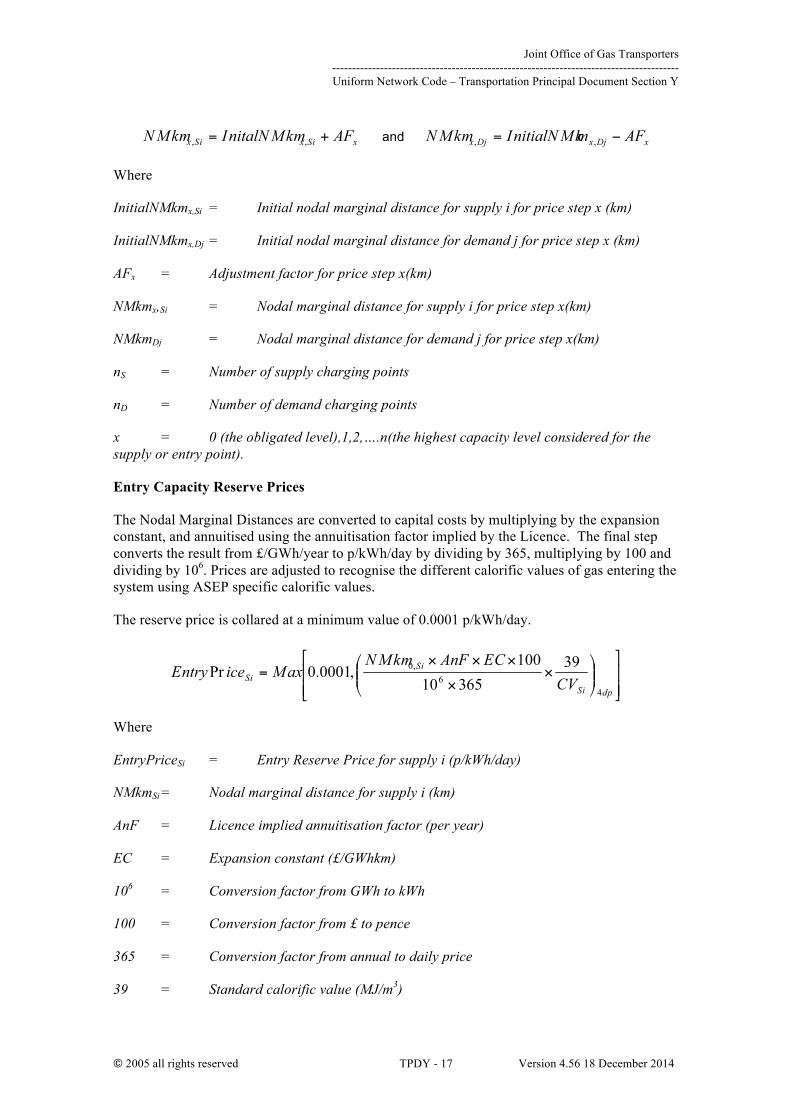
The Nodal Marginal Distance (NMkm) for each supply is then the Initial Nodal Marginal Distance plus the Adjustment Factor. The Nodal Marginal Distance for each demand is then the Initial Nodal Marginal Distance minus the Adjustment Factor.
Joint Office of Gas Transporters --------------------------------------------------------------------------------------- Uniform Network Code – Transportation Principal Document Section Y
© 2005 all rights reserved TPDY - 17 Version 4.56 18 December 2014
and
Where
InitialNMkmx,Si = Initial nodal marginal distance for supply i for price step x (km)
InitialNMkmx,Dj = Initial nodal marginal distance for demand j for price step x (km)
AFx = Adjustment factor for price step x(km)
NMkmx,Si = Nodal marginal distance for supply i for price step x(km)
NMkmDj = Nodal marginal distance for demand j for price step x(km)
nS = Number of supply charging points
nD = Number of demand charging points
x = 0 (the obligated level),1,2,….n(the highest capacity level considered for the supply or entry point).
Entry Capacity Reserve Prices
The Nodal Marginal Distances are converted to capital costs by multiplying by the expansion constant, and annuitised using the annuitisation factor implied by the Licence. The final step converts the result from £/GWh/year to p/kWh/day by dividing by 365, multiplying by 100 and dividing by 106. Prices are adjusted to recognise the different calorific values of gas entering the system using ASEP specific calorific values.
The reserve price is collared at a minimum value of 0.0001 p/kWh/day.
Where
EntryPriceSi = Entry Reserve Price for supply i (p/kWh/day)
NMkmSi = Nodal marginal distance for supply i (km)
AnF = Licence implied annuitisation factor (per year)
EC = Expansion constant (£/GWhkm)
106 = Conversion factor from GWh to kWh
100 = Conversion factor from £ to pence
365 = Conversion factor from annual to daily price
39 = Standard calorific value (MJ/m3)
Joint Office of Gas Transporters --------------------------------------------------------------------------------------- Uniform Network Code – Transportation Principal Document Section Y
© 2005 all rights reserved TPDY - 18 Version 4.56 18 December 2014
CVSi = Calorific value for supply i (MJ/m3)
4dp = Rounding to 4 decimal places of precision
Incremental Entry Capacity Step Prices
This section describes how the nodal marginal distances are used to calculate entry long run incremental costs for each ASEP.
Long run incremental costs are calculated for an ASEP by determining the difference between adjusted nodal marginal distances for each incremental capacity level and the obligated capacity level.
The differences in the adjusted marginal distances are converted into unit (incremental) costs (£/GWh) by multiplying it by the Expansion Constant11. These unit costs can then be converted into daily prices by applying the annuitisation factor. An adjustment to reflect the calorific value at the ASEP is also applied.
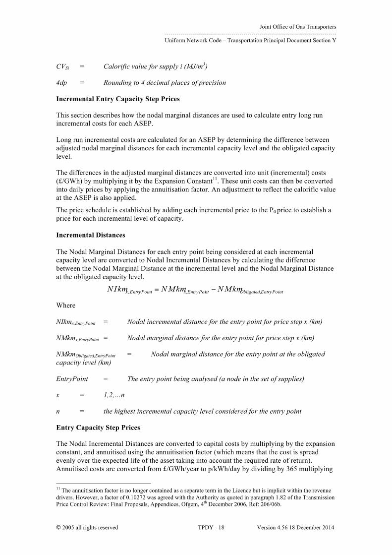
The price schedule is established by adding each incremental price to the P0 price to establish a price for each incremental level of capacity. Incremental Distances The Nodal Marginal Distances for each entry point being considered at each incremental capacity level are converted to Nodal Incremental Distances by calculating the difference between the Nodal Marginal Distance at the incremental level and the Nodal Marginal Distance at the obligated capacity level.
Where
NIkmx,EntryPoint = Nodal incremental distance for the entry point for price step x (km)
NMkmx,EntryPoint = Nodal marginal distance for the entry point for price step x (km)
NMkmObligated,EntryPoint = Nodal marginal distance for the entry point at the obligated capacity level (km)
EntryPoint = The entry point being analysed (a node in the set of supplies)
x = 1,2,…n
n = the highest incremental capacity level considered for the entry point
Entry Capacity Step Prices
The Nodal Incremental Distances are converted to capital costs by multiplying by the expansion constant, and annuitised using the annuitisation factor (which means that the cost is spread evenly over the expected life of the asset taking into account the required rate of return). Annuitised costs are converted from £/GWh/year to p/kWh/day by dividing by 365 multiplying
11 The annuitisation factor is no longer contained as a separate term in the Licence but is implicit within the revenue drivers. However, a factor of 0.10272 was agreed with the Authority as quoted in paragraph 1.82 of the Transmission Price Control Review: Final Proposals, Appendices, Ofgem, 4th December 2006, Ref: 206/06b.
Joint Office of Gas Transporters --------------------------------------------------------------------------------------- Uniform Network Code – Transportation Principal Document Section Y
© 2005 all rights reserved TPDY - 19 Version 4.56 18 December 2014
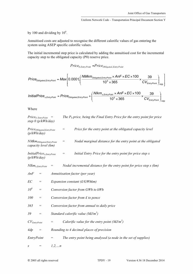
by 100 and dividing by 106.
Annuitised costs are adjusted to recognise the different calorific values of gas entering the system using ASEP specific calorific values.
The initial incremental step price is calculated by adding the annuitised cost for the incremental capacity step to the obligated capacity (P0) reserve price.
Where
Price0, EntryPoint = The P0 price, being the Final Entry Price for the entry point for price step 0 (p/kWh/day)
PriceObligated,EntryPoint = Price for the entry point at the obligated capacity level (p/kWh/day)
NMkmObligated,EntryPoint = Nodal marginal distance for the entry point at the obligated capacity level (km)
InitialPricex,EntryPoint = Initial Entry Price for the entry point for price step x (p/kWh/day)
NIkmx,EntryPoint = Nodal incremental distance for the entry point for price step x (km)
AnF = Annuitisation factor (per year)
EC = Expansion constant (£/GWhkm)
106 = Conversion factor from GWh to kWh
100 = Conversion factor from £ to pence
365 = Conversion factor from annual to daily price
39 = Standard calorific value (MJ/m3)
CVEntryPoint = Calorific value for the entry point (MJ/m3)
4dp = Rounding to 4 decimal places of precision
EntryPoint = The entry point being analysed (a node in the set of supplies)
x = 1,2,…n

Joint Office of Gas Transporters --------------------------------------------------------------------------------------- Uniform Network Code – Transportation Principal Document Section Y
© 2005 all rights reserved TPDY - 20 Version 4.56 18 December 2014
n = the highest incremental capacity level considered for the entry point
New Entry Points
In the event that a connecting pipe is required to be provided by National Grid for a new entry point, the initial price schedule calculation in section “Entry Capacity Step Prices” will be replaced by the following calculation:
Where
InitialPricex,EntryPoint = Initial Entry Price for the entry point for price step x (p/kWh/day)
PriceObligated,EntryPoint = Price for the entry point at the obligated capacity level (p/kWh/day)
NIkmx,EntryPoint = Nodal incremental distance for the entry point for price step x (km)
AnF = Annuitisation factor (per year)
EC = Expansion constant (£/GWhkm)
ConnectionCostx,EntryPoint = Estimate of the connection cost for the entry point for price step x (£m). This may require design and/or feasibility studies to be undertaken.
Capacityx,EntryPoint = Capacity level for the entry point for price step x (GWh)
106 = Conversion factor from GWh to kWh
100 = Conversion factor from £ to pence
365 = Conversion factor from annual to daily price
39 = Standard calorific value (MJ/m3)
CVEntryPoint = Calorific value for the entry point (MJ/m3)
4dp = Rounding to 4 decimal places of precision
EntryPoint = The entry point being analysed (a node in the set of supplies)
x = 1,2,…n
n = the highest incremental capacity level considered for the entry point
Ascending and Descending Price Schedules
Joint Office of Gas Transporters --------------------------------------------------------------------------------------- Uniform Network Code – Transportation Principal Document Section Y
© 2005 all rights reserved TPDY - 21 Version 4.56 18 December 2014
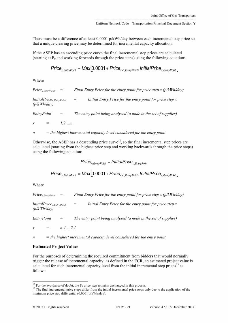
There must be a difference of at least 0.0001 p/kWh/day between each incremental step price so that a unique clearing price may be determined for incremental capacity allocation.
If the ASEP has an ascending price curve the final incremental step prices are calculated (starting at P0 and working forwards through the price steps) using the following equation:
Where
Pricex,EntryPoint = Final Entry Price for the entry point for price step x (p/kWh/day)
InitialPricex,EntryPoint = Initial Entry Price for the entry point for price step x (p/kWh/day)
EntryPoint = The entry point being analysed (a node in the set of supplies)
x = 1,2,…n
n = the highest incremental capacity level considered for the entry point
Otherwise, the ASEP has a descending price curve12, so the final incremental step prices are calculated (starting from the highest price step and working backwards through the price steps) using the following equation:
Where
Pricex,EntryPoint = Final Entry Price for the entry point for price step x (p/kWh/day)
InitialPricex,EntryPoint = Initial Entry Price for the entry point for price step x (p/kWh/day)
EntryPoint = The entry point being analysed (a node in the set of supplies)
x = n-1,…2,1
n = the highest incremental capacity level considered for the entry point
Estimated Project Values
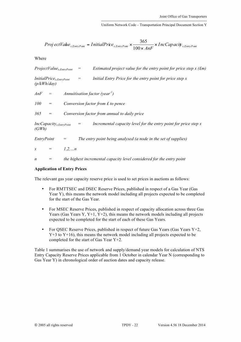
For the purposes of determining the required commitment from bidders that would normally trigger the release of incremental capacity, as defined in the ECR, an estimated project value is calculated for each incremental capacity level from the initial incremental step prices13 as follows:
12 For the avoidance of doubt, the P0 price step remains unchanged in this process. 13 The final incremental price steps differ from the initial incremental price steps only due to the application of the minimum price step differential (0.0001 p/kWh/day).
Joint Office of Gas Transporters --------------------------------------------------------------------------------------- Uniform Network Code – Transportation Principal Document Section Y
© 2005 all rights reserved TPDY - 22 Version 4.56 18 December 2014
Where
ProjectValuex,EntryPoint = Estimated project value for the entry point for price step x (£m)
InitialPricex,EntryPoint = Initial Entry Price for the entry point for price step x (p/kWh/day)
AnF = Annuitisation factor (year-1)
100 = Conversion factor from £ to pence
365 = Conversion factor from annual to daily price
IncCapacityx,EntryPoint = Incremental capacity level for the entry point for price step x (GWh)
EntryPoint = The entry point being analysed (a node in the set of supplies)
x = 1,2,…n
n = the highest incremental capacity level considered for the entry point
Application of Entry Prices
The relevant gas year capacity reserve price is used to set prices in auctions as follows:
• For RMTTSEC and DSEC Reserve Prices, published in respect of a Gas Year (Gas Year Y), this means the network model including all projects expected to be completed for the start of the Gas Year.
• For MSEC Reserve Prices, published in respect of capacity allocation across three Gas Years (Gas Years Y, Y+1, Y+2), this means the network models including all projects expected to be completed for the start of each of these Gas Years.
• For QSEC Reserve Prices, published in respect of future Gas Years (Gas Years Y+2, Y+3 to Y+16), this means the network model including all projects expected to be completed for the start of Gas Year Y+2.
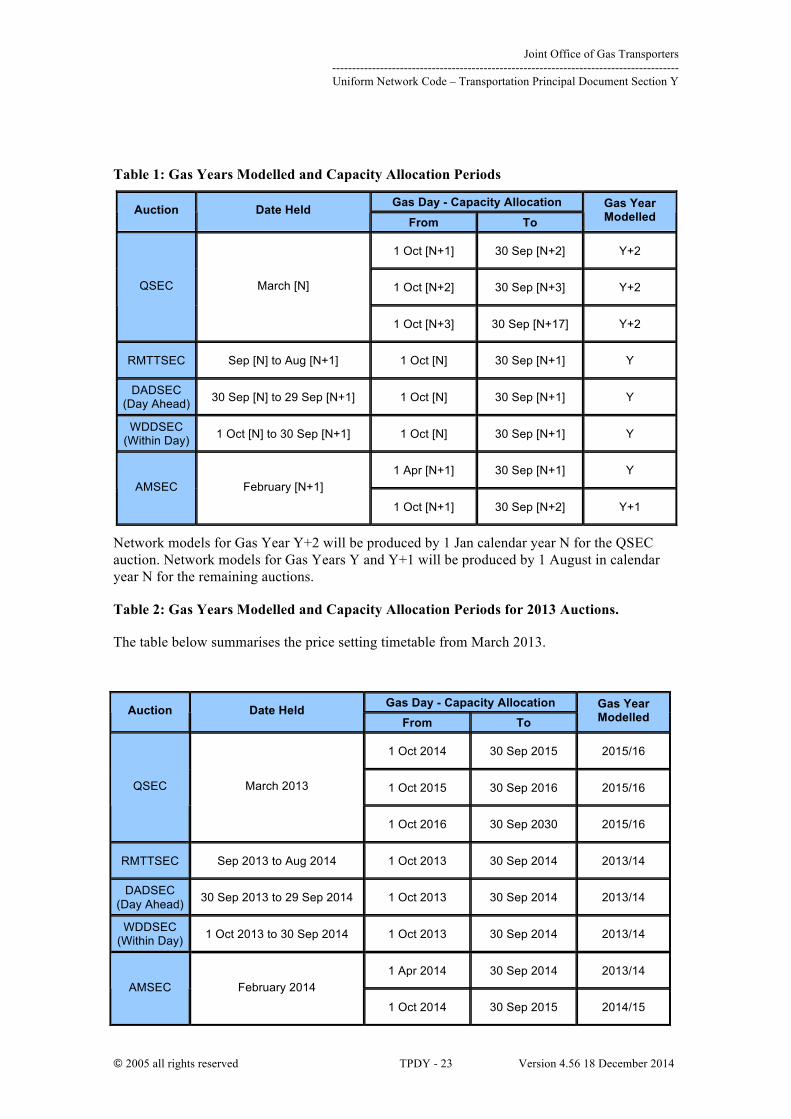
Table 1 summarises the use of network and supply/demand year models for calculation of NTS Entry Capacity Reserve Prices applicable from 1 October in calendar Year N (corresponding to Gas Year Y) in chronological order of auction dates and capacity release.
Joint Office of Gas Transporters --------------------------------------------------------------------------------------- Uniform Network Code – Transportation Principal Document Section Y
© 2005 all rights reserved TPDY - 23 Version 4.56 18 December 2014
Table 1: Gas Years Modelled and Capacity Allocation Periods
Network models for Gas Year Y+2 will be produced by 1 Jan calendar year N for the QSEC auction. Network models for Gas Years Y and Y+1 will be produced by 1 August in calendar year N for the remaining auctions.
Table 2: Gas Years Modelled and Capacity Allocation Periods for 2013 Auctions.
The table below summarises the price setting timetable from March 2013.
Gas Day - Capacity Allocation Auction Date Held From To
Gas Year Modelled
1 Oct [N+1] 30 Sep [N+2] Y+2
1 Oct [N+2] 30 Sep [N+3] Y+2 QSEC March [N]
1 Oct [N+3] 30 Sep [N+17] Y+2
RMTTSEC Sep [N] to Aug [N+1] 1 Oct [N] 30 Sep [N+1] Y
DADSEC (Day Ahead) 30 Sep [N] to 29 Sep [N+1] 1 Oct [N] 30 Sep [N+1] Y
WDDSEC (Within Day) 1 Oct [N] to 30 Sep [N+1] 1 Oct [N] 30 Sep [N+1] Y
1 Apr [N+1] 30 Sep [N+1] Y AMSEC February [N+1]
1 Oct [N+1] 30 Sep [N+2] Y+1
Gas Day - Capacity Allocation Auction Date Held From To
Gas Year Modelled
1 Oct 2014 30 Sep 2015 2015/16
1 Oct 2015 30 Sep 2016 2015/16 QSEC March 2013
1 Oct 2016 30 Sep 2030 2015/16
RMTTSEC Sep 2013 to Aug 2014 1 Oct 2013 30 Sep 2014 2013/14
DADSEC (Day Ahead) 30 Sep 2013 to 29 Sep 2014 1 Oct 2013 30 Sep 2014 2013/14
WDDSEC (Within Day) 1 Oct 2013 to 30 Sep 2014 1 Oct 2013 30 Sep 2014 2013/14
1 Apr 2014 30 Sep 2014 2013/14 AMSEC February 2014
1 Oct 2014 30 Sep 2015 2014/15

Joint Office of Gas Transporters --------------------------------------------------------------------------------------- Uniform Network Code – Transportation Principal Document Section Y
© 2005 all rights reserved TPDY - 24 Version 4.56 18 December 2014
Network models for Gas Year 2015/16 will be produced, so that prices are generated at least two months ahead of the QSEC auction, during January 2013. QSEC prices are therefore set using the network model for the year prior to the first year of incremental release. Network models for Gas Years 2013/14 and 2014/15 will be updated by 1 August 2010 for the remaining auctions. Prices for auctions other than QSEC are therefore set using the network model for the year of capacity release.
New Entry Points
For new NTS Entry Points, where no Legacy Incremental Entry Capacity or Funded Incremental Obligated Entry Capacity has been sold the entry capacity reserve price is set at the transportation model derived annuitized long run marginal cost for the relevant entry point with that entry point flowing at the obligated level.

Joint Office of Gas Transporters --------------------------------------------------------------------------------------- Uniform Network Code – Transportation Principal Document Section Y
© 2005 all rights reserved TPDY - 25 Version 4.56 18 December 2014
CHAPTER 3: COMMODITY CHARGES
NTS commodity charges consist of charges per unit of gas allocated to shippers at exit and entry.
The commodity charges on gas flows at NTS Storage facilities, other than on the amount of gas utilised as part of the operation of any NTS Storage facility, known as storage “own use” gas are zero. “Own use “gas is the difference between the quantity that is injected into storage and the quantity that is available for withdrawal back into the system.
“Own use” gas is treated as leaving the NTS at that exit point, and hence attracts the standard NTS commodity charge (both TO and SO components). The quantity of storage own use gas attributed to Users is notified by the Storage Manager to National Grid in accordance with the terms of the Storage Connection Agreement in respect of the NTS Storage Facility.
3.1 NTS TO Entry Commodity Charge
This is a charge per unit of gas allocated to shippers at entry terminals but not storage facilities. The charge is levied where National Grid forecasts that the entry capacity auction revenue will be below the target revenue.
The charge will be set to zero where entry capacity auction revenue is at, or above, the entry capacity target level. National Grid will assess its forecast entry capacity auction revenue following the AMSEC auction and, if necessary, determine a 12 month schedule of TO commodity charges to apply from the following October. National Grid would only depart from this schedule under exceptional circumstances.
3.2 NTS TO Entry Commodity Charge Rebate
The TO entry commodity rebate mechanism reduces any TO over-recovery resulting from NTS Entry Capacity auctions. The process may be triggered at the end of the formula year based on the outcome of all NTS Entry Capacity auctions that represent a TO revenue stream. This mechanism will only be triggered if there remains a residual over-recovery amount after taking into account any revenue redistributed by the buy-back offset mechanism as defined in 2.3.2 above and if this residual over-recovery is in excess of £1m (this equates to the minimum TO Entry Commodity price of 0.0001 p/kWh).
Trigger
Ø The TO Entry Commodity rebate mechanism will be triggered if there remains a residual over-recovery amount after taking into account any revenue redistributed by the buy-back offset mechanism
Ø The process will be triggered at the end of the formula year based on the outcome of all NTS Entry Capacity auctions that represent a TO revenue stream.
Ø Credits will only be paid if the residual over-recovery is in excess of £1M (this equates to the minimum TO Entry Commodity price of 0.0001 p/kWh)
Mechanism
Ø Any residual over-recovery revenue, taking into account any payments resulting from the buy-back offset process, will be available as a rebate to shippers
Joint Office of Gas Transporters --------------------------------------------------------------------------------------- Uniform Network Code – Transportation Principal Document Section Y
© 2005 all rights reserved TPDY - 26 Version 4.56 18 December 2014
Ø The ratio of the remaining TO over-recovery amount and the TO Entry Commodity Revenue paid will be calculated
Ø The ratio will be capped at 1 i.e. only the TO Entry Commodity revenue received will be rebated
Ø A rebate of TO Entry Commodity charges paid will be calculated based on the ratio
Ø The rebate would be paid following the formula year
3.3 NTS TO Entry Commodity Charge Credit
Trigger
Ø The credit, which represents a retrospective negative TO Entry Commodity charge, will be used if there remains a residual over-recovery amount after taking into account any revenue redistributed via the TO Entry Commodity Rebate Mechanism (as described above).
Ø The mechanism will be triggered, in the event of TO over-recovery, even if the buy-back offset mechanism had not been triggered or the TO Entry Commodity Rebate Mechanism had been triggered but had not been utilised due to a zero TO Entry Commodity rate having applied.
Ø The mechanism will be triggered at the end of the formula year based on the outcome of all NTS Entry Capacity auctions that represented a TO revenue stream.
Mechanism
Ø Any residual TO entry revenue remaining after taking into account credits resulting from the Entry Capacity buy-back offset and the TO Entry Commodity Rebate mechanisms will be available as a credit to shippers.
Ø Credits will only be paid based on relevant entry allocations i.e. those allocations that attract the Entry Commodity charge.
Ø Credits will only be paid if the residual over recovery is in excess of £1m (this equates to the minimum TO Entry Commodity price of 0.0001 p/kWh)
Ø Each Shipper’s credit will be calculated as a proportion of the total available credits based on the ratio of that Shipper’s SO Entry Commodity charges to the aggregate of all SO Entry Commodity charges paid over the formula year e.g. if the value of the credits paid through the proposed mechanism represents 5% of all SO Entry Commodity charges paid then each Shipper will receive a credit representing 5% of the SO Entry Commodity charges that it has paid over the formula year. For the avoidance of doubt, this calculation excludes optional (“short-haul”) entry commodity charges. The credit will be treated as TO for regulatory reporting.
Ø Credits will be paid following the end of the formula year. Note that NTS Entry Commodity charges for the last month of the formula year (March) are invoiced in the following May.

Joint Office of Gas Transporters --------------------------------------------------------------------------------------- Uniform Network Code – Transportation Principal Document Section Y
© 2005 all rights reserved TPDY - 27 Version 4.56 18 December 2014
3.4 NTS SO Entry & Exit (Flat) Commodity Charge
This is a charge per unit of gas transported by the NTS and is applied uniformly on both entry and exit flows at all NTS system points. The target revenue to be raised by the charge is the NTS SO allowed revenue, including any incentive additions or deductions, less any revenue to be obtained from the St. Fergus compression charge and the Optional NTS commodity tariff.
3.5 NTS Optional Commodity Charge “Shorthaul”
Shippers can elect to pay the optional tariff as an alternative to both the entry and exit NTS (SO & TO) commodity charges. The tariff is derived from the estimated cost of laying and operating a dedicated pipeline of NTS specification. A charging function has been calculated based on a range of flow rates and pipeline distances. The larger the load and the closer to an Entry point the smaller the NTS Optional Commodity Charge should be as this reflects the unit cost of laying a pipeline. Although the tariff is available to all daily-metered supply points, in practice it is therefore only attractive for large supply points situated close to terminals as at certain distances and loads it will become economic to pay standard Commodity charges.
In practice the Shipper nominates an Exit Point and a relevant (non-storage) entry point. Shippers can nominate a number of exit points against the same entry point but cannot nominate multiple entry points to the same exit point. The NTS Optional Commodity Charge is levied on the smaller of the two daily shipper allocations at these points, with the assumption made that any ‘extra’ gas must have come from another Entry point or alternatively flowed to another Exit point. For the purposes of invoicing all Exit throughput is charged at the NTS Optional Commodity rate with a reconciliation carried out a month later based on actual flows at these nominated points. To nominate an Exit point for the NTS Optional Commodity rate please contact the Unique Sites team at xoserve.
3.6 Compression Charge
An additional charge is payable where gas is delivered into the NTS at a lower pressure than that required, giving rise to a need for additional compression. The compression charge is derived from an analysis of costs at the compressor site and the annual throughput at that site.
3.7 NTS TO Exit Commodity Charge
This is a charge per unit of gas allocated to shippers at exit points but not storage facilities. The charge is levied where National Grid forecasts that the exit capacity revenue will be below the target revenue.
National Grid will assess its forecast exit capacity revenue following the relevant application periods and, if necessary, determine a 12 month schedule of TO commodity charges to apply from the following October. National Grid would only depart from this schedule under exceptional circumstances.
3.8 NTS Exit Commodity Charging at Storage
At present, National Grid does not levy commodity charges on gas flows at NTS Storage facilities, other than on an amount of gas, utilised, as part of the operation of any NTS Storage facility, known as storage “own use” gas. This is effectively the difference between the quantity that is injected into storage and the quantity that is available for withdrawal back into the system. For the purposes of charging, the “own use” gas is treated as leaving the NTS at that exit point, and hence attracts both the standard NTS SO & TO Exit (Flat) Commodity charges.
Joint Office of Gas Transporters --------------------------------------------------------------------------------------- Uniform Network Code – Transportation Principal Document Section Y
© 2005 all rights reserved TPDY - 28 Version 4.56 18 December 2014
The quantity of storage own use gas attributed to Users is notified by the Storage Manager to National Grid in accordance with the terms of the Storage Connection Agreement in respect of the NTS Storage Facility.

Joint Office of Gas Transporters --------------------------------------------------------------------------------------- Uniform Network Code – Transportation Principal Document Section Y
© 2005 all rights reserved TPDY - 29 Version 4.56 18 December 2014
CHAPTER 4: OTHER CHARGES
4.1 Other Shipper Services Charges
There are other charges applied to services which are required by some shippers but not by all, for example special allocation arrangements. It is more equitable to levy specific cost reflective charges for these services on those shippers that require them. Income from these charges is included in the regulated SO transportation income. These charges include:-
• charges for the administration processes required to manage the daily operations and invoicing associated with CSEPs;
• charges for the administration of allocation arrangements at shared supply meter points and Interconnectors; and
• charges for specific services at Interconnectors.
The methodology used to calculate the appropriate level of these charges is based on an assessment of the costs, incurred by xoserve, of the ongoing activities involved in providing the services. The charges are forward looking and take into account anticipated enhancements to the methods and systems used.
4.2 DN Pensions Deficit Charge
A specific annual cost allowance for the part-funding of the deficit in the NGUK Pension Scheme has been included in National Grid’s TO price control formula. In respect of the share of this allowance that arises from pension deficit costs associated with former employees of the DNs, the allowed cost is recovered via the application of a DN Pensions Deficit Charge which is levied on each of the DNOs on a monthly basis. The actual monthly pension charges for each DN are given in National Grid’s Statement of Charges and are in accordance with the total annual allowance as set out in Special Condition 2A of the Licence.
As the “target revenue” is fixed for each of the formula years in the Price Control period 2013 - 2021, we would anticipate that this should equal the recoverable revenue for each formula year. Hence this should avoid any “carry over” of allowable revenue from one formula year to the next.
4.3 NTS Entry Capacity Retention Charge
NTS Entry Capacity Substitution is where National Grid moves unsold non-incremental obligated entry capacity from one (donor) ASEP to meet the demand for incremental obligated entry capacity at a different (recipient) ASEP. Users are able to exclude capacity at potential donor ASEPs from being treated as substitutable capacity without having to buy and be allocated the capacity. To do this they are able to take out a “retainer”.
The retainer is valid for one year, covering all QSEC auctions (including ad-hoc auctions) held in this period. National Grid will exclude the relevant quantity from the substitution process, but the retainer will not create any rights to the User to be allocated or to use the capacity. The retainer will not prevent Users (including the User taking out the retainer) from buying that capacity at the ASEP in question in the period covered by the retainer.
The retainer is subject to a one-off charge which is payable via an ad hoc invoice raised within 2 months of the QSEC auction allocations being confirmed. If a User wishes to protect capacity
Joint Office of Gas Transporters --------------------------------------------------------------------------------------- Uniform Network Code – Transportation Principal Document Section Y
© 2005 all rights reserved TPDY - 30 Version 4.56 18 December 2014
for more than one year then a further retainer must be obtained each year and a charge will be payable each year for which a retainer is taken out.
Where any capacity covered by a retainer is allocated, a refund of the retention fee may be made; for example, for a retainer taken out for gas year 2013/14 in January 2010, a refund can be triggered by an allocation at the relevant ASEP made during a QSEC auction in 2010, 2011 and 2012, and an AMSEC auction in 2013 and 2014. For a full description of the capacity retainer process, see the “The Entry Capacity Substitution Methodology Statement”14.
NTS Entry Capacity Retention Charges, in regard to non-incremental obligated entry capacity, are calculated based on the minimal capacity charge rate of 0.0001 pence per kWh per day applying over a time period of 32 quarters; this equates to 0.2922 p/kWh of entry capacity retained.
NTS Entry Capacity Retention Charges and refunds in regard to non-incremental obligated entry capacity are treated as TO revenue; this would result in reduced TO Entry Commodity Charges in the case of charges incurred for retained capacity or increased TO Entry Commodity Charges in the case of subsequent refunds.1
14 The Entry Capacity Substitution Methodology Statement can be found on the National Grid website at; http://www.nationalgrid.com/uk/Gas/Charges/statements/ 1 Implementation of modification 0465V effective 06:00hrs on 02/02/2015, will add new paragraph 5.

Joint Office of Gas Transporters --------------------------------------------------------------------------------------- Uniform Network Code – Transportation Principal Document Section Y
© 2005 all rights reserved TPDY - 31 Version 4.56 18 December 2014
APPENDIX A – TREATMENT OF UNDER/OVER RECOVERY ‘K’
The following table defines the calculations used to calculate separate entry and exit K from the reported ‘Kt’ term defined within the National Grid Licence in respect of the NTS.
Net Position Interest Rate Adjustment (PRt)
Calculation
Net Recovery > 104% 3%
Net Recovery between 96% and 104% 1.5%
Net Recovery <96% 0%
KExt = (TORExCt-2 – MRExt-2) x (1+ (It-2 + PRt)/100) x (1+ (It-1 + 1.5)/100)
KEnt = (TOREnCt-2 – MREnt-2) x (1+ (It-2 + PRt)/100) x (1+ (It-1 + 1.5)/100)
Where:
KEnt: TO Entry Revenue adjustment factor in respect of formula year t for charging purposes
KExt: TO Exit Revenue adjustment factor in respect of formula year t for charging purposes
TOREnCt-2: TO Actual Revenue collected on Entry in year t-2
TORExCt-2: TO Actual Revenue collected on Exit in year t-2
MREnt-2: TO Maximum Allowed Revenue allocated to Entry in the Charging Methodology in year t-2
MRExt-2: TO Maximum Allowed Revenue allocated to Exit in the Charging Methodology in year t-2
It: Average Specified Rate in respect of formula year t
PRt: Interest Rate Adjustment in formula year t in accordance with Special Condition 2A of National Grid NTS’s Transporter Licence
Net Recovery: TO Revenue as a percentage of Maximum Allowed Revenue (Special Condition 2A of National Grid NTS’s Transporter Licence)

Joint Office of Gas Transporters --------------------------------------------------------------------------------------- Uniform Network Code – Transportation Principal Document Section Y
© 2005 all rights reserved TPDY - 32 Version 4.56 18 December 2014
Joint Office of Gas Transporters --------------------------------------------------------------------------------------- Uniform Network Code – Transportation Principal Document Section Y
© 2005 all rights reserved TPDY - 33 Version 4.56 18 December 2014
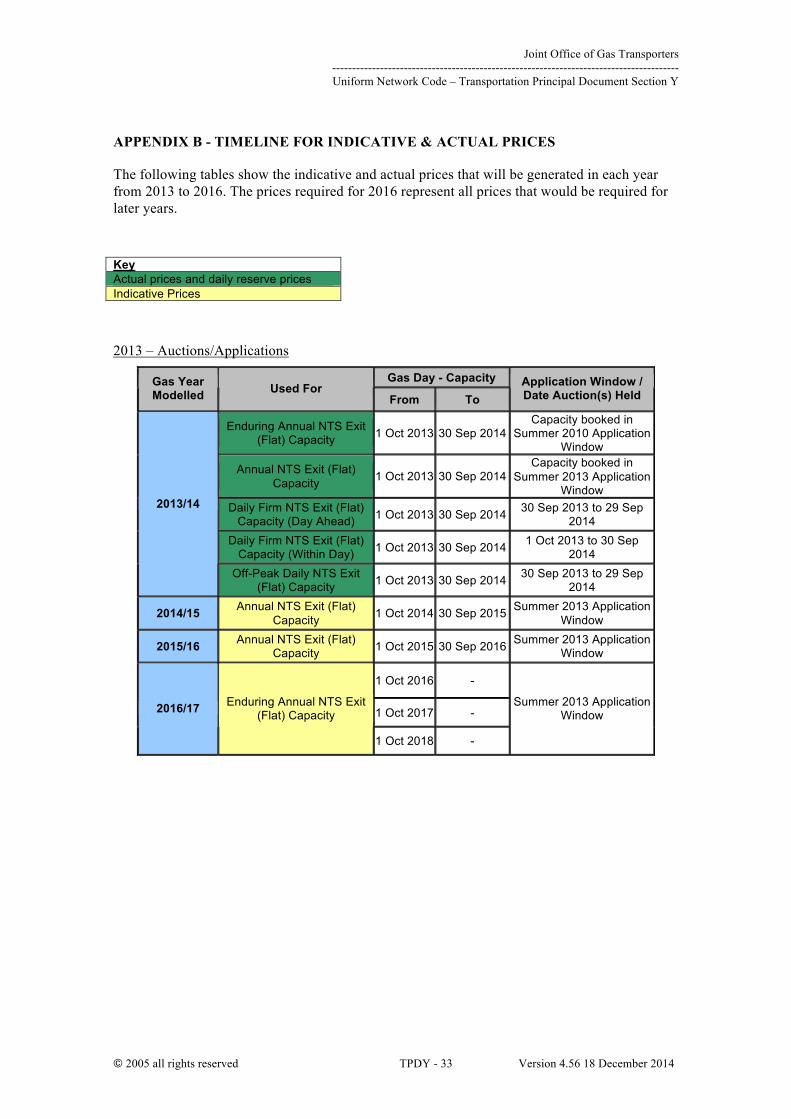
APPENDIX B - TIMELINE FOR INDICATIVE & ACTUAL PRICES
The following tables show the indicative and actual prices that will be generated in each year from 2013 to 2016. The prices required for 2016 represent all prices that would be required for later years.
Key Actual prices and daily reserve prices Indicative Prices
2013 – Auctions/Applications
Gas Day - Capacity Gas Year Modelled Used For
From To Application Window / Date Auction(s) Held
Enduring Annual NTS Exit (Flat) Capacity 1 Oct 2013 30 Sep 2014
Capacity booked in Summer 2010 Application
Window
Annual NTS Exit (Flat) Capacity 1 Oct 2013 30 Sep 2014
Capacity booked in Summer 2013 Application
Window Daily Firm NTS Exit (Flat)
Capacity (Day Ahead) 1 Oct 2013 30 Sep 2014 30 Sep 2013 to 29 Sep 2014
Daily Firm NTS Exit (Flat) Capacity (Within Day) 1 Oct 2013 30 Sep 2014 1 Oct 2013 to 30 Sep
2014
2013/14
Off-Peak Daily NTS Exit (Flat) Capacity 1 Oct 2013 30 Sep 2014 30 Sep 2013 to 29 Sep
2014
2014/15 Annual NTS Exit (Flat) Capacity 1 Oct 2014 30 Sep 2015 Summer 2013 Application
Window
2015/16 Annual NTS Exit (Flat) Capacity 1 Oct 2015 30 Sep 2016 Summer 2013 Application
Window
1 Oct 2016 -
1 Oct 2017 - 2016/17 Enduring Annual NTS Exit (Flat) Capacity
1 Oct 2018 -
Summer 2013 Application Window

Joint Office of Gas Transporters --------------------------------------------------------------------------------------- Uniform Network Code – Transportation Principal Document Section Y
© 2005 all rights reserved TPDY - 34 Version 4.56 18 December 2014
2014 – Auctions/Applications
Gas Day - Capacity Gas Year Modelled Used For
From To Application Window / Date Auction(s) Held
Enduring Annual NTS Exit (Flat) Capacity 1 Oct 2014 30 Sep 2015
Capacity booked in Summer 2011 Application
Window
Annual NTS Exit (Flat) Capacity 1 Oct 2014 30 Sep 2015
Capacity booked in Summer 2014 Application
Window Daily Firm NTS Exit (Flat)
Capacity (Day Ahead) 1 Oct 2014 30 Sep 2015 30 Sep 2014 to 29 Sep 2015
Daily Firm NTS Exit (Flat) Capacity (Within Day) 1 Oct 2014 30 Sep 2015 1 Oct 2014 to 30 Sep
2015
2014/15
Off-Peak Daily NTS Exit (Flat) Capacity 1 Oct 2014 30 Sep 2015 30 Sep 2014 to 29 Sep
2015
2015/16 Annual NTS Exit (Flat) Capacity 1 Oct 2015 30 Sep 2016 Summer 2014 Application
Window
2016/17 Annual NTS Exit (Flat) Capacity 1 Oct 2016 30 Sep 2017 Summer 2014 Application
Window
1 Oct 2017 -
1 Oct 2018 - 2017/18 Enduring Annual NTS Exit (Flat) Capacity
1 Oct 2019 -
Summer 2014 Application Window
2015 – Auctions/Applications
Gas Day - Capacity Gas Year Modelled Used For
From To Application Window / Date Auction(s) Held
Enduring Annual NTS Exit (Flat) Capacity 1 Oct 2015 30 Sep 2016
Capacity booked in Summer 2012 Application
Window
Annual NTS Exit (Flat) Capacity 1 Oct 2015 30 Sep 2016
Capacity booked in Summer 2015 Application
Window Daily Firm NTS Exit (Flat)
Capacity (Day Ahead) 1 Oct 2015 30 Sep 2016 30 Sep 2015 to 29 Sep 2016
Daily Firm NTS Exit (Flat) Capacity (Within Day) 1 Oct 2015 30 Sep 2016 1 Oct 2015 to 30 Sep
2016
2015/16
Off-Peak Daily NTS Exit (Flat) Capacity 1 Oct 2015 30 Sep 2016 30 Sep 2015 to 29 Sep
2016
2016/17 Annual NTS Exit (Flat) Capacity 1 Oct 2016 30 Sep 2017 Summer 2015 Application
Window
2017/18 Annual NTS Exit (Flat) Capacity 1 Oct 2017 30 Sep 2018 Summer 2015 Application
Window
1 Oct 2018 -
1 Oct 2019 - 2018/19 Enduring Annual NTS Exit (Flat) Capacity
1 Oct 2020 -
Summer 2015 Application Window
Joint Office of Gas Transporters --------------------------------------------------------------------------------------- Uniform Network Code – Transportation Principal Document Section Y
© 2005 all rights reserved TPDY - 35 Version 4.56 18 December 2014
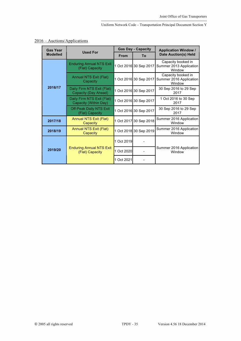
2016 – Auctions/Applications
Gas Day - Capacity Gas Year Modelled Used For
From To Application Window / Date Auction(s) Held
Enduring Annual NTS Exit (Flat) Capacity 1 Oct 2016 30 Sep 2017
Capacity booked in Summer 2013 Application
Window
Annual NTS Exit (Flat) Capacity 1 Oct 2016 30 Sep 2017
Capacity booked in Summer 2016 Application
Window Daily Firm NTS Exit (Flat)
Capacity (Day Ahead) 1 Oct 2016 30 Sep 2017 30 Sep 2016 to 29 Sep 2017
Daily Firm NTS Exit (Flat) Capacity (Within Day) 1 Oct 2016 30 Sep 2017 1 Oct 2016 to 30 Sep
2017
2016/17
Off-Peak Daily NTS Exit (Flat) Capacity 1 Oct 2016 30 Sep 2017 30 Sep 2016 to 29 Sep
2017
2017/18 Annual NTS Exit (Flat) Capacity 1 Oct 2017 30 Sep 2018 Summer 2016 Application
Window
2018/19 Annual NTS Exit (Flat) Capacity 1 Oct 2018 30 Sep 2019 Summer 2016 Application
Window
1 Oct 2019 -
1 Oct 2020 - 2019/20 Enduring Annual NTS Exit (Flat) Capacity
1 Oct 2021 -
Summer 2016 Application Window

Joint Office of Gas Transporters --------------------------------------------------------------------------------------- Uniform Network Code – Transportation Principal Document Section Y
© 2005 all rights reserved TPDY - 36 Version 4.56 18 December 2014

Joint Office of Gas Transporters --------------------------------------------------------------------------------------- Uniform Network Code – Transportation Principal Document Section Y
© 2005 all rights reserved TPDY - 37 Version 4.56 18 December 2014
APPENDIX C – CLASSIFICATION OF SUPPLY POINTS
Beach Supplies
Ø Bacton excluding BBL and IUK
Ø Barrow
Ø Burton Point (also known as “Point of Ayr)
Ø Easington including Langeled, excluding Rough
Ø St Fergus
Ø Teesside including Excelerate
Ø Theddlethorpe
Ø Wytch Farm (Onshore field)
Interconnectors
Ø BBL
Ø IUK
Long Range Storage
Ø Rough
LNG Importation (incorporating onshore storage)
Ø Isle of Grain
Ø Milford Haven
Mid-range Storage
Existing sites and those currently under construction, due to be operational in the relevant gas year, as outlined in Section 2.3 of the Ten Year Statement
Short-range Storage
Ø Avonmouth
Ø Glenmavis
Ø Partington

Joint Office of Gas Transporters --------------------------------------------------------------------------------------- Uniform Network Code – Transportation Principal Document Section Y
© 2005 all rights reserved TPDY - 38 Version 4.56 18 December 2014
Glossary
1 in 20 Peak Day Demand
The peak day demand that, in a long series of winters, with connected load being held at the levels appropriate to the winter in question, would be exceeded in one out
of 20 winters, each winter being counted only once.
Obligated Entry Capacity
The amount of System Entry Capacity which National Grid is required to make available to Users pursuant to the Licence .
Capacity Year
The period from 1 April in any year until and including 31 March in the following year.
Exit Zone
Each Local Distribution Zone (LDZ) is divided into one or more NTS exit zones for determining charges.
Entry Capacity Release methodology statement
The statement prepared and published by National Grid in accordance with Special Condition 9B of the Licence.
Formula Year
The period from 1 April in any year until and including 31 March in the following year.
Local Distribution Zone
(LDZ)
Part of the system, other than the NTS, for the time being designated by National Grid as such, and described in the Ten Year Statement, or (where the context requires) the area in which such part of the system is located.
National Transmission
System (NTS)
Part of the system for the time being designated by National Grid as such, and described in the Ten Year Statement.
Supply Point
A System Exit Point comprising the Supply Meter Point or Supply Meter Points for the time being registered in the name of a User pursuant to a Supply Point Registration.
Ten Year Statement
A statement (or revised statement) required to be prepared by National Grid pursuant to Special Condition 7A of the Licence.

Joint Office of Gas Transporters --------------------------------------------------------------------------------------- Uniform Network Code – Transportation Principal Document Section Y
© 2005 all rights reserved TPDY - 39 Version 4.56 18 December 2014
2. The Gas Transmission Connection Charging Methodology
INTRODUCTION
1. This Methodology which is published in accordance with Standard Licence Condition 4B of the Licence applies exclusively to Design Works and Construction Works associated with:
a) new NTS connections;
b) modifications to existing NTS connection apparatus;
c) disconnections of existing NTS connection apparatus; and
d) diversions of sections of the NTS.
2. It should be noted that in addition to a physical connection to the NTS, the following additional requirements also need to be satisfied before gas can flow through that connection as specified in the Network Code:
a) National Grid will require gas shippers at the connection point (or DNs in the case of Exit capacity for NTS/LDZ Offtakes) to acquire the appropriate Entry and/or Exit capacity in accordance with the Network Code and the ECR and ExCR methodology statements;
b) National Grid will require a customer to enter into a Supply Point Network Exit Agreement (NExA), Connected System Exit Point (CSEP) NExA, NTS/LDZ Supplemental Agreement, Network Entry Agreement (NEA), Interconnector Agreement or Storage Connection Agreement (SCA), as appropriate.
3. It should also be noted that the following Reinforcement will be triggered as a result of the release of Entry and Exit capacity and not as part of the connection process:
a) For Entry capacity – all necessary Reinforcement;
b) For Exit capacity – only that Reinforcement that is needed upstream of the Connection Charging Point (“CCP”).
Joint Office of Gas Transporters --------------------------------------------------------------------------------------- Uniform Network Code – Transportation Principal Document Section Y
© 2005 all rights reserved TPDY - 40 Version 4.56 18 December 2014
SECTION 1 - PRINCIPLES
4. National Grid will recover the Actual Costs incurred when it carries out Design Works and Construction Works, i.e. customers are charged on a cost pass-through basis.
5. Charges reflect the cost of labour, materials, and any other expenses required to carry out the work to the customer’s requirements including applicable Lane Rental Charges15. Each cost element will carry an appropriate level of overhead.
6. National Grid will calculate Estimated Costs and Actual Costs using:
a) National Grid’s fully absorbed direct costs associated with undertaking any works, i.e. including appropriate overhead costs;
b) Individually tendered rates for indirect costs, and
c) Any other costs not included above related to the provision of connection activities.
7. National Grid may carry out work additional to that which is required to meet the requirements of the customer to ensure that it develops the NTS in an economic and efficient manner. Where this occurs, the cost of any additional works will not be charged to the customer.
8. All charges are made subject to the appropriate Standard Conditions of Contract (SCCs), which will be made available on request in respect of specific projects.
9. Bespoke quotations will identify any assumptions that are used in the determination of the Estimated Costs.
10. National Grid will enter into commercial agreements with customers on the basis of Estimated Costs, and will seek an advance payment of these Estimated Costs in accordance with both the relevant commercial agreement and National Grid’s prevailing credit policy.
11. However, to ensure that the Actual Costs of the project are recovered as described in paragraph 11 above, when final payment is due, as specified in the relevant commercial agreement, National Grid will compare Actual Costs with Estimated Costs invoiced to date and charge for the additional costs incurred or refund any overpayment, as may be the case.
15 National Grid is obliged to pass on only those costs which have been efficiently incurred.

Joint Office of Gas Transporters --------------------------------------------------------------------------------------- Uniform Network Code – Transportation Principal Document Section Y
© 2005 all rights reserved TPDY - 41 Version 4.56 18 December 2014
SECTION 2 - CONNECTION CHARGING METHODOLOGY
Connection – Load Size Threshold
12. Loads (or sources of gas) below 58,600,000kWh (2 million therms) per annum shall not be connected, or be permitted to connect, to the NTS. In exceptional circumstances where suitable alternative connections to a Distribution Network are not available, then National Grid will consider requests on a case by case basis.
Design Philosophy
13. Design Works rely upon information provided by the customer and will also use other publicly available information as well as information relating to the NTS.
14. National Grid will construct apparatus on a least project cost ‘fit for purpose’ basis taking into account the customer’s requirements and its relevant Licence obligations. Where there are different fit for purpose design solutions, which meet a customer’s requirements, National Grid will base the charge to the customer on the solution with the lowest overall cost of construction. However, National Grid may choose to implement a solution that has a lower whole-life cost, with the balance of the cost of construction being met by National Grid.
15. The term ‘fit for purpose’ refers to a design that will safely transport the requisite quantity of gas at an appropriate pressure throughout the life of the apparatus taking into account the Gas Act requirement for economic pipe-line system development.
Design Charges
16. The Estimated Costs in respect of Design Works will be identified within quotations provided by National Grid. These quotations will be dependent upon the information provided by the customer, other publicly available information and information relating to the NTS.
17. If the Customer subsequently changes the data on which National Grid has based the Estimated Costs, then the Estimated Costs will be updated accordingly
18. National Grid will complete the Design Works before the Construction Works are commenced and irrespective of whether the Construction Works take place at a later date. The customer will be required to pay the Actual Costs of the Design Works.
19. In instances where the known requirements of a connection are insufficient to enable progression straight to a Conceptual Design Study, an initial Feasibility Study may be undertaken in order to refine the potential options and associated Estimated Costs for the Conceptual Design Works and Construction Works stages.. Customers may also request a Feasibility Study to analyse potential connections options.
20. For the avoidance of doubt a Feasibility Study will be subject to a separate commercial agreement from the Conceptual Design Study.
21. If, as agreed with the customer, the Design Works are split into stages, e.g. Feasibility Study followed by Conceptual Design Study then National Grid will provide the Estimated Costs and timescales for undertaking each study in turn prior to entering into each agreement. The customer will be obliged to have paid the Actual Costs of each

Joint Office of Gas Transporters --------------------------------------------------------------------------------------- Uniform Network Code – Transportation Principal Document Section Y
© 2005 all rights reserved TPDY - 42 Version 4.56 18 December 2014
stage before the commencement of a subsequent phase.
22. Where the customer requests National Grid to design a System Extension to the customer’s premises, National Grid will supply the customer with a copy of the design report once a study has been completed. Should the customer not choose National Grid to construct the System Extension, then the customer may use the information in this report, under licence, in respect of the hire of an alternative provider to construct the pipeline. Should the customer choose to use an alternative provider to construct the pipeline, then the customer must inform National Grid and ask for a revised quotation for the connection.
Construction Charges
23. The Estimated Costs in respect of Construction Works will be identified in a quotation provided by National Grid and will be based on the best information available to National Grid, including wherever possible, utilising the costs of recent similar projects.
24. The output of a related Conceptual Design Study will normally include a more accurate value for the Estimated Costs of the Construction Works.
25. The customer will be required to pay the Actual Costs of the Construction Works.
NTS Connections: Connection Offers and Application Fees
25A. National Grid NTS shall establish, publish and review the types of NTS Connections and the fixed Initial Connection Offer Connection Application Fee payable by the Connection Applicant as follows: (a) on an annual basis to reflect any changes to National Grid NTS staff costs; or (b) on an ad-hoc basis where a modification is made to the contents of Section V,
paragraph 13 - NTS Connections.
25B. The Connection Application Fee for a Connection Offer shall reflect the average National Grid NTS fully absorbed costs required to produce the information contained in a Connection Offer.
Remotely Operable Valve (ROV) Installations
26. All new connections will include an ROV Installation which may be situated either:
a) at a point on the NTS, where the customer wishes to:
i. construct and connect a pipeline with a view to owning and operating the pipeline (such pipeline would not be a System Extension as it would not be owned and operated by National Grid), or
ii. construct and connect a pipeline with the intention that it will transfer to National Grid under a Taking Ownership Agreement (in which case it would become a System Extension); or
b) at the termination point of a System Extension constructed by National Grid.
The costs of the ROV Installation form a part of the connection charge irrespective of whether the connection is for Exit, Entry or Bidirectional purposes.
27. However, where a connection is requested at or adjacent to an existing National Grid
Joint Office of Gas Transporters --------------------------------------------------------------------------------------- Uniform Network Code – Transportation Principal Document Section Y
© 2005 all rights reserved TPDY - 43 Version 4.56 18 December 2014
site, National Grid will at its sole discretion determine the most appropriate point and design of the connection taking into account potential costs of connection, future operational costs, security of supply and operational flexibility.
28. National Grid does not provide gas flow and energy measurement equipment for transmission connections.
29. In addition to the equipment provided by National Grid, there are several technical requirements that a customer must fulfil if it is to have a connection to the NTS. These relate principally to the customer’s metering and telemetry equipment and, where relevant, Gas Quality Instrumentation.
Gas Quality Instrumentation for Entry and Bidirectional connections
30. All connections that are to be used for the entry of gas to the NTS require Gas Quality Instrumentation to be installed by the customer.
31. National Grid’s requirements in respect of the quality of gas entering the NTS are contained in the Transmission Ten Year Statement,
System Extensions and Reinforcement for Entry (including the Entry element of Bidirectional) connections
32. The need for System Extensions and Reinforcement to accommodate Entry flows at the connection point will be determined when National Grid receives auction signals for incremental entry capacity in accordance with the Licence and Network Code.
33. The costs of System Extension and/or Reinforcement will not be charged to the customer within the connection charge, but will instead be taken into account in the auction price applicable in any capacity auction.
34. Where separately identifiable Reinforcement is required only to accommodate Exit flows to a Bidirectional connection, then this Reinforcement will be dealt with under the section below.
System Extensions and Reinforcements for Exit (including the Exit element of Bidirectional) connections
35. System Extensions for Exit purposes are treated as a component of connection apparatus (unless provided by the customer) and their costs form part of the connection charge as discussed in section ‘Design Charges’ above.
36. The need for Reinforcement to accommodate Exit flows at the connection point will be determined when National Grid receives the appropriate signals for Incremental Exit Capacity in accordance with the Licence and Network Code.
37. National Grid apportions the cost of Reinforcement according to its location in relation to the Connection Charging Point (“CCP”). Reinforcement downstream of the CCP is charged to the customer under the terms of this Statement and will form part of the connection. Reinforcement upstream of the CCP is not directly charged but may be funded by National Grid where required to enable the provision of capacity under the terms of the ExCR methodology statement.
38. The System Extension element is the only component that can be provided by the

Joint Office of Gas Transporters --------------------------------------------------------------------------------------- Uniform Network Code – Transportation Principal Document Section Y
© 2005 all rights reserved TPDY - 44 Version 4.56 18 December 2014
customer.
Quotation Assumptions
39. Quotations for Design Studies and/or Construction Works will include a statement to the effect that the customer, in accepting the quotation will also be accepting that the assumptions are appropriate and understood. If it is determined later that any stated assumption is incorrect, National Grid will determine in accordance with the Standard Conditions of Contract (SCCs) whether the Estimated Costs should be varied and the customer will be informed. In such circumstances, National Grid may cease or delay works pending the customer’s acceptance of any increased Estimated Costs.
Taking Ownership of Connection Apparatus
40. Subject to the conditions detailed below, National Grid will take ownership of fit for purpose connection apparatus that is connected to the NTS and that is not intended to be operated by another system operator (e.g. a Connected System Operator that has received a Gas Act derogation).
41. Conditions relating to taking ownership:
a) National Grid and the customer must have entered into a Taking Ownership Agreement before any works are undertaken in respect of the design or construction of any apparatus that the customer wishes National Grid to take into ownership. The Taking Ownership Agreement will allow National Grid to carry out audit work at all stages of the project from design through to construction and commissioning in order to determine whether the apparatus to be installed by the customer and adopted by National Grid is fit for purpose.
b) The apparatus shall NOT:
i. be designed to operate at pressures below those normally found in the NTS at the connection point;
ii. form part of a system of pipes that includes any apparatus that will become a connected system that will not also be owned by National Grid;
iii. include gas flow, energy measurement and associated equipment; and
iv. include apparatus that is not fit for purpose.
42. National Grid will charge for audit work carried out under a Taking Ownership Agreement. Charges will be based upon the cost of employing National Grid staff together with any costs incurred by service providers employed by National Grid and will include an appropriate level of overhead charges.

Joint Office of Gas Transporters --------------------------------------------------------------------------------------- Uniform Network Code – Transportation Principal Document Section Y
© 2005 all rights reserved TPDY - 45 Version 4.56 18 December 2014
SECTION 4 – DISCONNECTION, DIVERSION AND MODIFICATION OF GAS CONNECTION APPARATUS
43. In general, National Grid will follow the same principles that it applies to connection works in respect of charges for disconnection, diversion and modification services, subject to appropriate commercial arrangements.
44. The precise nature of these works is likely to vary from project to project. Therefore, in order to determine the estimated charges for these works, it may be necessary for National Grid to undertake an assessment of the potential options under a Feasibility Study agreement, which the customer will be responsible for funding. The Customer may also wish to request a Feasibility Study in order to understand the potential options and to provide the Estimated Costs of the remaining Design Works phases and Construction Works. National Grid will provide an estimate of the charges and timescales for undertaking such an assessment prior to entering into an agreement.

Joint Office of Gas Transporters --------------------------------------------------------------------------------------- Uniform Network Code – Transportation Principal Document Section Y
© 2005 all rights reserved TPDY - 46 Version 4.56 18 December 2014

Joint Office of Gas Transporters --------------------------------------------------------------------------------------- Uniform Network Code – Transportation Principal Document Section Y
© 2005 all rights reserved TPDY - 47 Version 4.56 18 December 2014
Appendix A – Definitions
1. Actual Costs are the costs efficiently incurred, in line with Section 1 of this Statement, by National Grid in carrying out the Design Works or Construction Works, as may be the case. Where they are incurred, National Grid will pass on the cost of efficiently incurred connections-related Lane Rental Charges to customers.
2. Bidirectional connections are connections that combine elements of both Entry and Exit connections to allow flows of gas onto and from the NTS, e.g. storage facilities, interconnector.
3. A Conceptual Design Study which may follow a Feasibility Study typically forms the majority of the Design Works and includes the provision of engineering analysis to assess the impact of the customer request for a connection, disconnection, diversion or modification. Outputs will include the provision of indicative drawings, material schedules and the Estimated Costs of the Construction Works.
4. The Connection Charging Point (CCP) is the closest economically feasible point on the NTS, which is deemed to have sufficient capacity to supply the new Exit load disregarding existing Exit loads. The CCP creates the financial distinction between Connection Costs that are fully chargeable to the person concerned (i.e. downstream) and upstream Reinforcement costs which may be funded by National Grid where required to enable the provision of capacity under the terms of the ExCR methodology statement.
5. Construction Works are:
a) the detailed design required to produce final drawings and material schedules; and
b) the physical works, including:
• commissioning;
• excavation, backfill and reinstatement in the public highway and excavation, backfill and routine reinstatement on private land, except where requested otherwise; and
• works associated with telemetry and other systems required to enable National Grid to operate the connection apparatus in accordance with its statutory, Licence and Network Code obligations.
6. Design Works are the preparatory design of the connection, disconnection, diversion or modification, which must occur before Construction Works can commence. Design Works typically only involve the preparation of a Conceptual Design Study but in some instances may include a Feasibility Study (in one or more phases) prior to the Conceptual Design Study. For the avoidance of doubt, detailed design forms part of the Construction Works.
7. A Disconnection occurs when existing connection apparatus is disconnected.
8. A Distribution Network (DN) is a geographically defined network of distribution pipes, typically comprising interconnected local transmission, intermediate pressure, medium pressure and low pressure networks, connected to and downstream of the NTS (see Special Condition 1A of the Licence for formal definition).
Joint Office of Gas Transporters --------------------------------------------------------------------------------------- Uniform Network Code – Transportation Principal Document Section Y
© 2005 all rights reserved TPDY - 48 Version 4.56 18 December 2014
9. A Diversion is a change made to the route of an existing NTS pipeline or the relocation of other gas transportation (not normally connecting pipe associated) assets.
10. Entry connections are connections to delivery facilities processing gas from gas producing fields or LNG vaporisation (i.e. importation) facilities, for the purpose of delivering gas into the NTS.
11. Estimated Costs are the estimated costs of Design Works or Construction Works, as may be the case, calculated on the basis of the costs that National Grid expects to incur.
12. Exit connections are connections that allow gas to be offtaken from the NTS to premises (a ‘Supply Point’), to Distribution Networks or to Connected System Exit Points (CSEPs). There are several types of connected system including:
a) A pipeline system operated by another gas transporter; and
b) Any other non-National Grid pipeline transporting gas to premises consuming more than 2,196MWh (75,000 therms) per annum.
13. A Feasibility Study may form the first part of the Design Works to evaluate the full requirements of a connection or modification etc. and provide sufficient detail to enable progression to a Conceptual Design Study. Alternatively a customer may wish to request a Feasibility Study in order to understand the Estimated Costs of the Conceptual Design Works and Construction Works or to consider different connection options.
14. Gas Quality Instrumentation comprises instrumentation that will be installed by the customer to monitor compliance of gas entering the NTS with legislative and contractual specifications.
15. Incremental Exit Capacity is as defined in Paragraph 1 of Special Condition 1A of the Licence.
16. A Metering Installation may exist at an NTS Offtake and will typically comprise of a combination of;
a) Filters;
b) Meters;
c) Pre heating equipment;
d) Pressure regulators; and
e) Associated pipework
At NTS Offtakes constructed prior to approximately 2001, the Metering Installation may be owned by National Grid. For information, charges for such installations are covered by National Grid’s Metering Charges Statement, which is available on the National Grid website: http://www.nationalgrid.com/uk/Gas/Charges/statements/metering/
17. A Modification is any change made to an existing connection, and associated equipment.
18. The National Transmission System (NTS) is that part of the pipeline system for the
Joint Office of Gas Transporters --------------------------------------------------------------------------------------- Uniform Network Code – Transportation Principal Document Section Y
© 2005 all rights reserved TPDY - 49 Version 4.56 18 December 2014
time being designated by National Grid as such and described in the National Grid Ten Year Statement.
19. Network Code means the network code prepared by National Grid, as from time to time modified, pursuant to the Licence. National Grid’s Network Code comprises the provisions set out in the Uniform Network Code (UNC), more details of which can be obtained at the Joint Office website: www.gasgovernance.co.uk.
20. An NTS/LDZ Offtake is the exit connection from the NTS to a Distribution Network as defined in the Network Code - Transportation Principle Document Section A3.4.3.
21. Reinforcement: National Grid must ensure that the NTS has sufficient capacity to supply new and existing demands at the applicable pressures and to transport new and existing gas supplies. NTS pressures affected by the connection of a new load (or an increase in load at an existing connection) may cause National Grid to need to reinforce the NTS, prior to the load/supply coming on stream. This reinforcement may take the form of new pipelines being laid or the installation, modification of other equipment to increase the pressure within the NTS or commercial alternatives to physical works.
22. A Remotely Operable Valve (ROV) Installation comprises the apparatus, constructed by National Grid, at the interface between the NTS and apparatus provided by a third party and will typically include a valve as required with remote operation actuation, full bore bypass and telemetry. ROV Installation apparatus will remain in National Grid ownership irrespective of the ownership of the up/downstream system.
23. Standard Conditions of Contract (SCCs) are described in paragraph 0.
24. A System Extension is a new connecting pipeline, constructed by National Grid, which runs from the existing NTS to a location specified by the customer. In order to effect isolation and maintenance of System Extensions, they typically require two ROV Installations, one at each end with the addition of ‘Pipeline Inspection Gauge (PIG) trap’ facilities at both ends to allow inline inspections.

Joint Office of Gas Transporters --------------------------------------------------------------------------------------- Uniform Network Code – Transportation Principal Document Section Y
© 2005 all rights reserved TPDY - 50 Version 4.56 18 December 2014

Joint Office of Gas Transporters --------------------------------------------------------------------------------------- Uniform Network Code – Transportation Principal Document Section Y
© 2005 all rights reserved TPDY - 51 Version 4.56 18 December 2014
Appendix B – Additional Points Relating to Capacity
Capacity booking
The provision of a connection does not confer any rights on a party to offtake or introduce gas. Gas may only be offtaken / introduced by a Registered User who is a party to the Network Code and has been licensed by the Gas and Electricity Markets Authority to do so.
Allocation of available capacity
National Grid will make capacity available in accordance with the Network Code and the ECR and ExCR methodology statement rules.

Joint Office of Gas Transporters --------------------------------------------------------------------------------------- Uniform Network Code – Transportation Principal Document Section Y
© 2005 all rights reserved TPDY - 52 Version 4.56 18 December 2014

Joint Office of Gas Transporters --------------------------------------------------------------------------------------- Uniform Network Code – Transportation Principal Document Section Y
© 2005 all rights reserved TPDY - 53 Version 4.56 18 December 2014
PART B – DN TRANSPORTATION CHARGING METHODOLOGY
The Gas Distribution Transportation Charging Methodology
1. Introduction
1.1 Gas distribution transportation charges consist of LDZ System charges, Customer charges, LDZ Exit Capacity NTS (ECN) charges and Administration charges.
1.2 For transportation to Supply Points directly connected to the distribution system the LDZ System, Customer and Administration charges are applicable. For transportation to Connected System Exit Points (CSEPs) the LDZ System and Administration charges are applicable.
1.3 The LDZ System charges and the Customer charges are set so as to maintain the proportional split of revenue recovery between them determined by the methodology. The levels of these charges are scaled proportionately to recover the target level of revenue. The LDZ ECN charges are set to aim to recover the level of cost incurred by the DN for NTS Exit Capacity in respect of NTS/LDZ offtakes in the Distribution Network. The levels of the Administration charges are based on the costs of providing the services and these charges are not scaled to recover any given proportion of the targeted revenue.
2. Split of revenue recovery between LDZ System and Customer Charges
2.1 The target balance of revenue recovery between LDZ System charges and Customer charges for each DN is based upon a network-specific analysis of the split of relevant costs. The target revenue recovery for LDZ System charges includes revenue for the Standard LDZ System charge, the Optional LDZ System charge and the LDZ System Entry commodity charge. The costs are taken from the regulatory reporting packs submitted to Ofgem.
2.2 Customer charges reflect costs relating to service pipes funded by the transporter and the costs of emergency work relating to service pipes and supply points (i.e. not including any costs associated with gas mains). Service pipe costs include all operational and depreciation costs associated with DN-connected service pipes; these costs also include the replacement of such pipes and service pipe leakage. The relevant portion of support, employee overheads and work management costs of supporting Customer cost activities, based on direct work activity costs are attributed to the Customer cost category.
2.3 LDZ System charges reflect costs which include the cost of all work relating to assets upstream of the service pipe (including the gas mains to which the service pipes are connected) and those costs associated with managing the flow of gas through the system including capacity management. Accordingly, costs for all activities upstream of service pipes relating to the maintenance, replacement and repair of mains and larger pipes, as well as energy management work and the construction of new pipes are included in this cost category. The relevant portion of support, employee overheads and work management costs of supporting LDZ System cost activities, based on direct work activity costs are attributed to the LDZ System cost category. Depreciation costs associated with gas mains and Local Transmission System (LTS) pipes and LDZ System activity assets are attributed to the LDZ System cost category. All odorant and shrinkage costs except for service pipe leakage are attributed to the LDZ System cost

Joint Office of Gas Transporters --------------------------------------------------------------------------------------- Uniform Network Code – Transportation Principal Document Section Y
© 2005 all rights reserved TPDY - 54 Version 4.56 18 December 2014
category.
2.4 The network-specific estimate of the split of relevant costs is assessed using an average of an appropriate number of years for which data on a consistent basis is available for each network.
2.5 The current target revenue recovery splits are as shown in the table below.
Target Revenue Recovery Split between LDZ System and Customer Charges
LDZ System Customer
East of England 70.5% 29.5%
London 68.1% 31.9%
North West 73.7% 26.3%
West Midlands 74.0% 26.0%
Scotland Gas Networks 71.2% 28.8%
Southern Gas Networks 72.8% 27.2%
Northern Gas Networks 71.2% 28.8%
Wales & West 71.8% 28.2%
3. Split of revenue recovery between LDZ System Capacity and Commodity Charges
3.1 The capacity element of the LDZ System charges is targeted to recover 95%, and the commodity element of the LDZ System charges is targeted to recover 5%, of the revenue from the LDZ system charges. This split is based on an assessment of the extent to which LDZ System associated costs are related to throughput or to system capacity. The 95:5 split applies to all the DNs.
3.2 The split described in paragraph 3.1 applies to the Standard LDZ System capacity and commodity charges. The LDZ System Entry commodity charge revenue is not taken into account for the purposes of determining the split.
4. Standard LDZ System Charges
4.1 All the data underlying the Standard LDZ System Charges is derived on a Network specific basis.
4.2 The distribution networks contain a series of pipe networks split into four main pressure tiers - Local Transmission System (LTS), Intermediate Pressure System (IPS), Medium Pressure System (MPS) and Low Pressure System (LPS). Because it accounts for the majority of the total system costs the LPS is then sub-divided on the basis of pipe diameter into a further eight sub-tiers.

Joint Office of Gas Transporters --------------------------------------------------------------------------------------- Uniform Network Code – Transportation Principal Document Section Y
© 2005 all rights reserved TPDY - 55 Version 4.56 18 December 2014
4.3 All LDZ System related costs, other than those attributed to LDZ System Entry Points, are attributed across these pressure tiers and sub-tiers.
4.4 The methodology below describes the derivation of the capacity charge function and is based on peak daily flows. A similar calculation, based on annual flows, is carried out to determine the commodity charge function.
4.5 The average cost of utilisation is calculated for each of the main pressure tiers of the system.
4.6 The probability of a load within a consumption band using any given pressure tier is determined by an analysis of where supply points of different sizes tend to connect to the system. Combining the average cost of utilisation with the probability of connection generates a tier charge for an average load within any given band. These tier charges are added together to give the total relative charge for a load within the consumption band to use the system.
4.7 To provide a workable basis for charging individual customers of differing sizes, the total average unit costs of utilising each tier of the distribution network are plotted. Functions are fitted to the data points representing the total unit costs such that the overall measure of error is minimised.
4.8 For the purposes of deriving charging functions the data points for the consumption bands are grouped into 3 charging bands:
4.8.1 For the 0 to 73.2 MWh/a charging band a fixed unit charge is determined. The rate applies to directly connected Supply Points and CSEPs;
4.8.2 For the 73.2 to 732 MWh/a charging band a fixed unit charge is determined. The rate applies to directly connected Supply Points and CSEPs;
4.8.3 For the 732 MWh/a and above charging band, functions based on a power of the peak daily load (SOQ) are fitted. There are separate power functions for directly connected Supply Points and for CSEPs as the cost data justified separate functions for the >732 MWh charging band.
4.9 The form of the LDZ System functions is currently derived on a national basis.
5.
6. Optional LDZ System Charge
6.1 The rationale for the Optional LDZ System charge is that, for large DN-connected loads located close to the NTS, the standard LDZ System charges can appear to give perverse economic incentives for the construction of new pipelines to supply loads that are already connected to the transportation system, or for potential new loads to build lengthier and costlier pipelines than are available via nearby DN connections. This may give rise to economically inefficient bypass of the Distribution Network system, and unnecessary duplication of infrastructure.
6.2 The level of the Optional LDZ System charge is based on the estimated costs to the Distribution Network of laying and connecting a dedicated pipeline for a range of flow rates and distances from the NTS.
Joint Office of Gas Transporters --------------------------------------------------------------------------------------- Uniform Network Code – Transportation Principal Document Section Y
© 2005 all rights reserved TPDY - 56 Version 4.56 18 December 2014
6.3 The costs considered in deriving the Optional LDZ System charge include the capital cost of laying the hypothetical pipeline and other capital costs relating to connection, metering, volumetric control and other requirements, and the ongoing direct and indirect costs of the hypothetical pipeline.
6.4 The level of the Optional LDZ System charge is independent of the overall level of revenue recovery targeted and so the level of the charging function remains unchanged until its cost basis is reanalysed.
6.5 Shipper Users opting for the Optional LDZ System charge pay this charge instead of the Standard LDZ System capacity and commodity charges.
7. LDZ System Entry Commodity Charge
7.1 LDZ System Entry commodity charges are payable in respect of gas delivered to the LDZ System at LDZ System Entry Points. For each LDZ System Entry Point the charge is a fixed unit commodity charge applicable to all gas delivered to the LDZ System. The unit rate may vary by LDZ System Entry Point and may be positive, resulting in a charge, or negative, resulting in a credit.
7.2 The LDZ System Entry commodity charge will be determined for each LDZ System Entry Point as the summation of the unit rates in respect of:
7.2.1 Opex Costs
(a) The unit rate will be determined in respect of the forecast operating costs incurred by the DN associated with the provision or operation of:
(i) the entry facilities related to the LDZ System Entry Point; and
(ii) any network assets which have been provided for, or are operated solely for, the management of gas flows from LDZ System Entry Points. Where such network assets are provided or operated solely for the management of flows from one LDZ System Entry Point then the forecast operating costs will be wholly allocated to that LDZ System Entry Point. Where such network assets are provided or operated for the management of flows from more than one LDZ System Entry Point then the forecast operating costs will be appropriately allocated between each relevant LDZ System Entry Point in proportion to the estimated cost causality.
(b) The unit rate will be determined as Forecast operating costs / Forecast entry gas flow, expressed as pence per kWh.
(c) The unit rate will be re-determined periodically to take account of changes to the forecast operating costs and forecast gas entry flows. In the intervening period between such redeterminations, the unit rate may be determined for a period by reference to the previously determined unit rate and the application of an appropriate RPI inflation factor reflecting the change in RPI since the last determination.
7.2.2 DN Usage Credit
(a) The DN Usage credit unit rate will be determined as the sum of the unit rates in

Joint Office of Gas Transporters --------------------------------------------------------------------------------------- Uniform Network Code – Transportation Principal Document Section Y
© 2005 all rights reserved TPDY - 57 Version 4.56 18 December 2014
respect of:
(i) ECN Credit
(A) The unit rate in respect of the ECN Credit for a LDZ System Entry Point will reflect the deemed saving in the cost of booked NTS Exit Capacity for the DN due to the forecast availability of gas flows at the LDZ System Entry Point leading to deemed lower levels of booked NTS Exit Capacity than otherwise.
(B) The unit rate is based on the average LDZ ECN charge for the whole DN multiplied by a Dependability Factor and then converted into a commodity equivalent charge. The Dependability Factor is set at a level which is equivalent to the load factor for the LDZ System Entry Point so that in the practice these figures cancel each other out in the calculation of the unit rate credit.
(C) The average LDZ ECN charge for the DN is calculated as:
where:
ECNz is the LDZ ECN charge in zone z;
SOQz is the forecast Supply Point capacity in zone z; and
means the sum across all NTS Exit Zones z within the DN.
(D) From this the unit rate credit, expressed as p/kWh, in respect of ECN Credit is equivalent to the numerical value of the average LDZ ECN charge, expressed as p/pdkWh/day and is independent of the flow characteristics at each LDZ System Entry Point, i.e. an average LDZ ECN charge of X p/pdkWh/day will lead to a unit rate in respect of ECN Credit of X p/kWh for each LDZ System Entry Point within that DN.
(ii) LDZ System Credit
(A) The unit rate credit in respect of LDZ system usage reflects the notional typical reduced usage of the LDZ System tiers by gas delivered into the LDZ System from the LDZ System Entry Point relative to that for gas delivered into the LDZ System from NTS/LDZ Offtakes. The credit is calculated individually for each LDZ System Entry Point and is dependent on the Highest Utilisation Tier for gas from the LDZ System Entry Point.
(B) The Highest Utilisation Tier is defined as the higher (in terms of pressure) of:

Joint Office of Gas Transporters --------------------------------------------------------------------------------------- Uniform Network Code – Transportation Principal Document Section Y
© 2005 all rights reserved TPDY - 58 Version 4.56 18 December 2014
(1) the tier at which gas enter into the LDZ from the LDZ System Entry Point;
(2) the tier which gas from the LDZ System Entry Point is, via within-network compression, moved to (this is not applicable for gas which is not subject to within-network compression).
(C) The tiers which are considered for the purposes of paragraph 7.2.2(a)(ii)(B) are (in descending order of pressure):
(1) Local Transmission System (LTS);
(2) Intermediate Pressure System (IPS);
(3) Medium Pressure System (MPS);
(4) Low Pressure System (LPS).
(D) The unit rate credit in respect of LDZ System usage is then determined as the sum of the Utilisation Rates for the tiers having higher pressure than the applicable Highest Utilisation Tier, as follows:
Highest Utilisation Tier Unit Rate Credit
LTS Zero
IPS LTS Utilisation Rate
MPS IPS Utilisation Rate plus LTS Utilisation Rate
LPS MPS Utilisation Rate plus IPS Utilisation Rate plus LTS Utilisation Rate
(E) The Utilisation Rate for each of the tiers is determined from the analysis of LDZ System utilisation used to determine the Standard LDZ System commodity charging functions, as set out in the methodology for determining the Standard LDZ System Charges. The Utilisation Rate for a tier is calculated as:
Utilisation Rate = 20 x Unit Commodity Cost for tier
where:
the Unit Commodity Cost is the Commodity Cost of utilising the tier based upon the LDZ System commodity charges being targeted to recover 5% of the LDZ System charge revenue and where the Commodity Costs are scaled by a constant multiplicative factor such that the sum of the Commodity Costs for the four tiers referred to in paragraph 7.2.2(a)(ii)(C) is equal to the LDZ System commodity charge rate for the 0 to 73.2 MWh/a charging band referred to in paragraph 4.7.1.
Joint Office of Gas Transporters --------------------------------------------------------------------------------------- Uniform Network Code – Transportation Principal Document Section Y
© 2005 all rights reserved TPDY - 59 Version 4.56 18 December 2014
(F) In this manner the unit rates in respect of the LDZ System credits should always be consistent with the Standard LDZ System commodity charges applicable for the same period.
7.3 The overall LDZ System Entry commodity charge may be positive (a charge) or negative (a credit) depending on the relative magnitude of the unit rates in respect of Opex Costs and DN Usage Credit.
8. Customer Charges
8.1 Customer charges reflect Supply Point costs, primarily costs relating to service pipes and emergency work relating to service pipes and supply points. The customer charge methodology is based on an attribution of the costs across Supply Points grouped into a number of consumption bands.
8.2 The costs are made up of two cost pools, broadly comprising costs associated with service pipes and costs associated with emergency work. Each cost pool is then divided among the consumption bands based on weighted consumer numbers by consumption band. The weightings are derived from estimates of how the costs of providing each of the services vary with consumption band. A total average cost per Supply Point is then calculated for each consumption band.
8.3 Functions are developed that best fit the relationship between supply point size and total average cost per supply point. The peak supply point capacity (SOQ) is used as a measure of supply point size.
8.4 For Supply Points up to 73.2 MWh/a, the Customer charge is a fixed unit capacity charge.
8.5 For Supply Points between 73.2 and 732 MWh/annum, the Customer charge consists of a fixed daily charge which varies with meter-reading frequency and a fixed unit capacity charge.
8.6 For Supply Points in excess of 732 MWh/annum, the Customer charge is a capacity charge whose unit rate is determined by a function based on a power of the peak daily load (SOQ).
9. LDZ Exit Capacity NTS (ECN) Charges
9.1 The LDZ ECN Charges are effective from 1 October 2012 and are a pence per peak day kWh charge applied to the supply point SOQ to determine the amount payable. The charge has a single unit rate within each Exit Zone.
9.2 The level of the LDZ ECN charges for any Exit Zone is set each year to reflect the forecast average unit NTS charges for capacity at the NTS/LDZ Offtakes which make up that Exit Zone. The target revenue for setting the level of the LDZ ECN charges is the initial allowance set out in the Transporter’s Licence (defined as AExt) and adjusted to the outturn money value, using the appropriate inflation factor for the relevant year, plus any true-up for the difference between initial set allowance and the actual exit capacity costs for the Formula Year two years previously plus or minus the ECNK.
9.3 The ECNK is managed separately from the overall K for the purposes of setting the levels of the LDZ Exit Capacity NTS charges. For Formula Year 2015/16 onwards, it is
Joint Office of Gas Transporters --------------------------------------------------------------------------------------- Uniform Network Code – Transportation Principal Document Section Y
© 2005 all rights reserved TPDY - 60 Version 4.56 18 December 2014
calculated as the difference between the revenue collected from the LDZ ECN charges and the amounts paid to NG NTS in respect of the Exit Capacity Charges in the Formula Year two years previously, plus or minus any ECNK from the period two years previously. ECNK for 2014/15 is defined to be zero.
9.4 K means the Distribution Network Transportation Activity Revenue adjustment factor to the Distribution Network Transportation Activity Revenue in respect of over or under recovery for a Distribution Network in a Formula Year.
10. Administration Charges
10.1 There are specific administration charges for some services which are required by some Shipper Users but not by all. These administration charges are:
10.1.1 Charges for the administration processes required to manage the daily operations and invoicing associated with CSEPs;
10.1.2 Charges for the administration of allocation arrangements at Shared Supply Meter Points.
10.2 The methodology used to calculate the appropriate level of these charges is based on an assessment of the costs incurred of the ongoing activities involved in providing the services. The charges are forward looking and take into account anticipated enhancements to the methods and systems used.