tpe, tped series 2000 - grundfosnet.grundfos.com/appl/ccmsservices/public/literature/...3. general...
TRANSCRIPT

TPE, TPED Series 2000Installation and operating instructions
GRUNDFOS INSTRUCTIONS

En
glis
h (G
B)
English (GB) Installation and operating instructions
Original installation and operating instructions.
CONTENTSPage
1. Symbols used in this document
2. General informationThese installation and operating instructions are a supplement to installation and operating instructions for the corresponding standard pumps TP, TPD. For instructions not mentioned specifically here, please see installation and operating instructions for the standard pump.
3. General descriptionGrundfos TPE, TPED Series 2000 pumps have standard motors with integrated frequency converter. The pumps are for single-phase or three-phase mains connection.
The pumps have a built-in PI controller and are set up with a differential-pressure sensor enabling control of the differential pressure across the pump.
The pumps are typically used as circulator pumps in large heating or cooling water systems with variable demands.
3.1 Settings
The desired setpoint can be set in three different ways:
• directly on the pump control panel. It is possible to choose between two different control modes, i.e. proportional pressure and constant pressure.
• via an input for external setpoint signal
• by means of the Grundfos wireless remote control R100.
All other settings are made by means of the R100. Important parameters such as actual value of control parameter, power consumption, etc. can be read via the R100.
3.2 Twin-head pumps
Twin-head pumps do not require any external controller.
1. Symbols used in this document 2
2. General information 2
3. General description 23.1 Settings 23.2 Twin-head pumps 2
4. Mechanical installation 34.1 Motor cooling 34.2 Outdoor installation 3
5. Electrical connection 35.1 Cable requirements 35.2 Electrical connection - single-phase pumps 35.3 Electrical connection - three-phase pumps up to 7.5
kW 65.4 Electrical connection - three-phase pumps, 11-22 kW 85.5 Signal cables 115.6 Bus connection cable 115.7 Communication cable for TPED pumps 11
6. Modes 126.1 Overview of modes 126.2 Operating mode 126.3 Control mode 126.4 Factory setting 13
7. Setting by means of control panel, single-phase pumps 14
7.1 Setting of head 147.2 Setting to max. curve duty 147.3 Setting to min. curve duty 147.4 Start/stop of pump 14
8. Setting by means of control panel, three-phase pumps 15
8.1 Setting of control mode 158.2 Setting of head 158.3 Setting to max. curve duty 158.4 Setting to min. curve duty 168.5 Start/stop of pump 16
9. Setting by means of R100 169.1 Menu OPERATION 189.2 Menu STATUS 199.3 Menu INSTALLATION 20
10. Setting by means of PC Tool E-products 22
11. Priority of settings 22
12. External forced-control signals 2212.1 Start/stop input 2212.2 Digital input 22
13. External setpoint signal 23
14. Bus signal 23
15. Other bus standards 23
16. Indicator lights and signal relay 24
17. Insulation resistance 26
18. Emergency operation (only 11-22 kW) 26
19. Maintenance and service 2719.1 Cleaning of the motor 2719.2 Relubrication of motor bearings 2719.3 Replacement of motor bearings 2719.4 Replacement of varistor (only 11-22 kW) 2719.5 Service parts and service kits 27
20. Technical data - single-phase pumps 2820.1 Supply voltage 2820.2 Overload protection 2820.3 Leakage current 2820.4 Inputs/outputs 28
21. Technical data - three-phase pumps up to 7.5 kW 2821.1 Supply voltage 2821.2 Overload protection 28
21.3 Leakage current 2821.4 Inputs/output 28
22. Technical data - three-phase pumps, 11-22 kW 2922.1 Supply voltage 2922.2 Overload protection 2922.3 Leakage current 2922.4 Inputs/output 29
23. Other technical data 29
24. Disposal 31
Warning
Prior to installation, read these installation and operating instructions. Installation and operation must comply with local regulations and accepted codes of good practice.
Warning
If these safety instructions are not observed, it may result in personal injury!
Warning
The surface of the product may be so hot that it may cause burns or personal injury.
Caution If these safety instructions are not observed, it may result in malfunction or damage to the equipment.
NoteNotes or instructions that make the job easier and ensure safe operation.
2
En
gli
sh
(G
B)
4. Mechanical installation4.1 Motor cooling
To ensure sufficient cooling of motor and electronics, observe the following requirements:
• Make sure that sufficient cooling air is available.
• Keep the temperature of the cooling air below 40 °C.
• Keep cooling fins and fan blades clean.
4.2 Outdoor installation
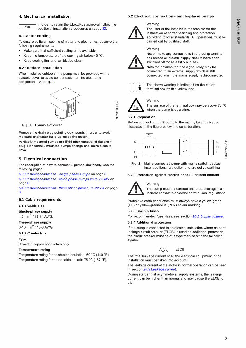
When installed outdoors, the pump must be provided with a suitable cover to avoid condensation on the electronic components. See fig. 1.
Fig. 1 Example of cover
Remove the drain plug pointing downwards in order to avoid moisture and water build-up inside the motor.
Vertically mounted pumps are IP55 after removal of the drain plug. Horizontally mounted pumps change enclosure class to IP54.
5. Electrical connectionFor description of how to connect E-pumps electrically, see the following pages:
5.2 Electrical connection - single-phase pumps on page 3
5.3 Electrical connection - three-phase pumps up to 7.5 kW on page 6
5.4 Electrical connection - three-phase pumps, 11-22 kW on page 8.
5.1 Cable requirements
5.1.1 Cable size
Single-phase supply
1.5 mm2 / 12-14 AWG.
Three-phase supply
6-10 mm2 / 10-8 AWG.
5.1.2 Conductors
Type
Stranded copper conductors only.
Temperature rating
Temperature rating for conductor insulation: 60 °C (140 °F).
Temperature rating for outer cable sheath: 75 °C (167 °F).
5.2 Electrical connection - single-phase pumps
5.2.1 Preparation
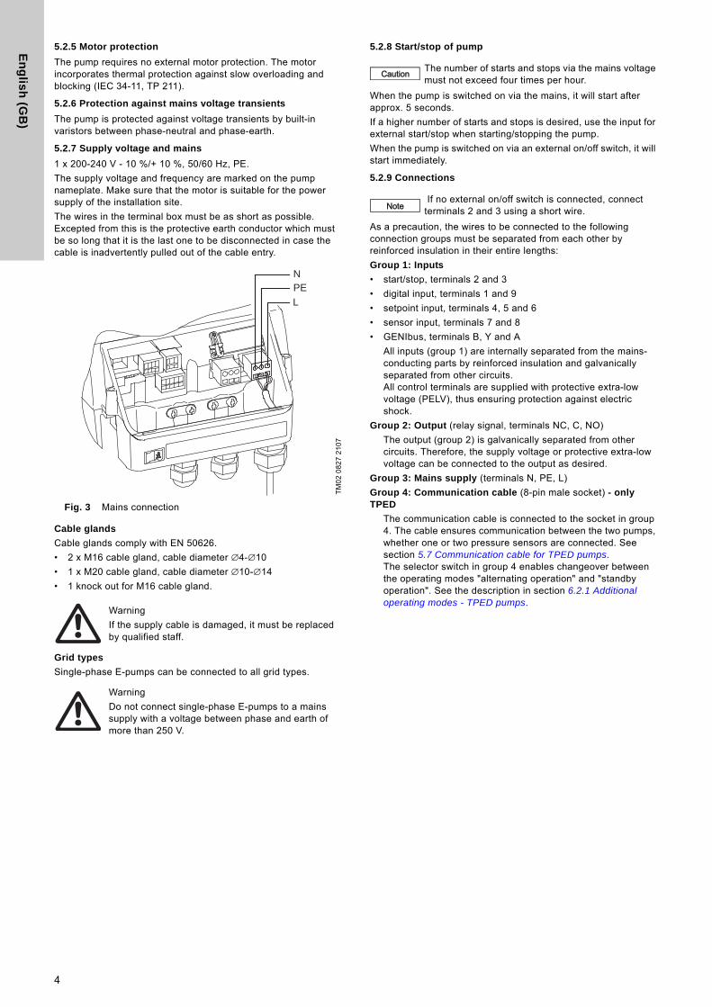
Before connecting the E-pump to the mains, take the issues illustrated in the figure below into consideration.
Fig. 2 Mains-connected pump with mains switch, backup fuse, additional protection and protective earthing
5.2.2 Protection against electric shock - indirect contact
Protective earth conductors must always have a yellow/green (PE) or yellow/green/blue (PEN) colour marking.
5.2.3 Backup fuses
For recommended fuse sizes, see section 20.1 Supply voltage.
5.2.4 Additional protection
If the pump is connected to an electric installation where an earth leakage circuit breaker (ELCB) is used as additional protection, the circuit breaker must be of a type marked with the following symbol:
The total leakage current of all the electrical equipment in the installation must be taken into account.
The leakage current of the motor in normal operation can be seen in section 20.3 Leakage current.
During start and at asymmetrical supply systems, the leakage current can be higher than normal and may cause the ELCB to trip.
NoteIn order to retain the UL/cURus approval, follow the additional installation procedures on page 32.
TM
02
85
14
03
04
Warning
The user or the installer is responsible for the installation of correct earthing and protection according to local standards. All operations must be carried out by qualified staff.
Warning
Never make any connections in the pump terminal box unless all electric supply circuits have been switched off for at least 5 minutes.
Note for instance that the signal relay may be connected to an external supply which is still connected when the mains supply is disconnected.
The above warning is indicated on the motor terminal box by this yellow label.
Warning
The surface of the terminal box may be above 70 °C when the pump is operating.
TM
02
07
92
01
01
Warning
The pump must be earthed and protected against indirect contact in accordance with local regulations.
N
PE
L
N
L
PE
ELCB
ELCB
3
En
glis
h (G
B)
5.2.5 Motor protection
The pump requires no external motor protection. The motor incorporates thermal protection against slow overloading and blocking (IEC 34-11, TP 211).
5.2.6 Protection against mains voltage transients
The pump is protected against voltage transients by built-in varistors between phase-neutral and phase-earth.
5.2.7 Supply voltage and mains
1 x 200-240 V - 10 %/+ 10 %, 50/60 Hz, PE.
The supply voltage and frequency are marked on the pump nameplate. Make sure that the motor is suitable for the power supply of the installation site.
The wires in the terminal box must be as short as possible. Excepted from this is the protective earth conductor which must be so long that it is the last one to be disconnected in case the cable is inadvertently pulled out of the cable entry.
Fig. 3 Mains connection
Cable glands
Cable glands comply with EN 50626.
• 2 x M16 cable gland, cable diameter ∅4-∅10
• 1 x M20 cable gland, cable diameter ∅10-∅14
• 1 knock out for M16 cable gland.
Grid types
Single-phase E-pumps can be connected to all grid types.
5.2.8 Start/stop of pump
When the pump is switched on via the mains, it will start after approx. 5 seconds.
If a higher number of starts and stops is desired, use the input for external start/stop when starting/stopping the pump.
When the pump is switched on via an external on/off switch, it will start immediately.
5.2.9 Connections
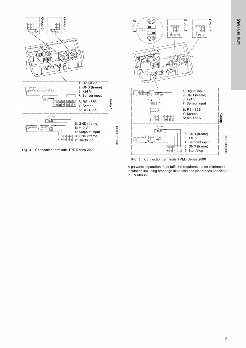
As a precaution, the wires to be connected to the following connection groups must be separated from each other by reinforced insulation in their entire lengths:
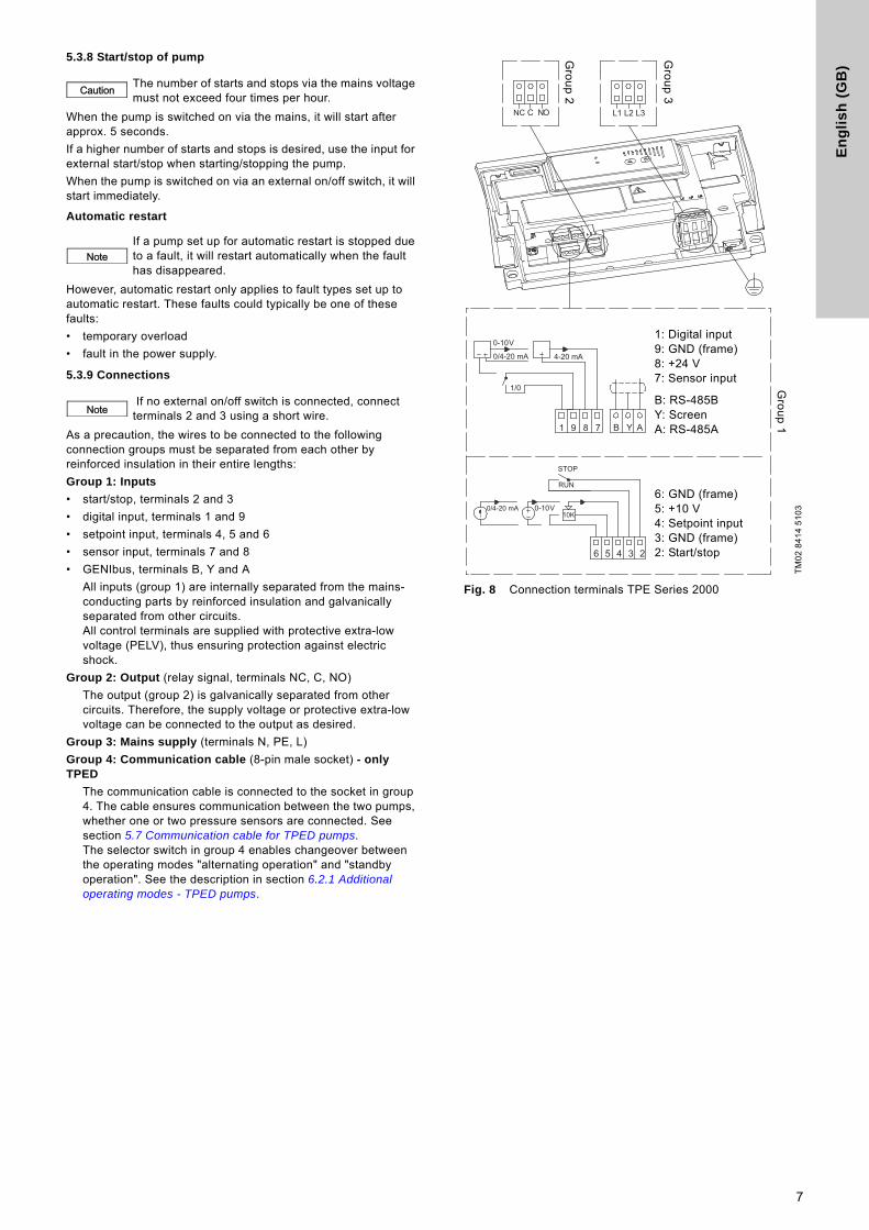
Group 1: Inputs
• start/stop, terminals 2 and 3
• digital input, terminals 1 and 9
• setpoint input, terminals 4, 5 and 6
• sensor input, terminals 7 and 8
• GENIbus, terminals B, Y and A
All inputs (group 1) are internally separated from the mains-conducting parts by reinforced insulation and galvanically separated from other circuits.All control terminals are supplied with protective extra-low voltage (PELV), thus ensuring protection against electric shock.
Group 2: Output (relay signal, terminals NC, C, NO)
The output (group 2) is galvanically separated from other circuits. Therefore, the supply voltage or protective extra-low voltage can be connected to the output as desired.
Group 3: Mains supply (terminals N, PE, L)
Group 4: Communication cable (8-pin male socket) - only TPED
The communication cable is connected to the socket in group 4. The cable ensures communication between the two pumps, whether one or two pressure sensors are connected. See section 5.7 Communication cable for TPED pumps.The selector switch in group 4 enables changeover between the operating modes "alternating operation" and "standby operation". See the description in section 6.2.1 Additional operating modes - TPED pumps.
TM
02
08
27
21
07
Warning
If the supply cable is damaged, it must be replaced by qualified staff.
Warning
Do not connect single-phase E-pumps to a mains supply with a voltage between phase and earth of more than 250 V.
PEL
N
Caution The number of starts and stops via the mains voltage must not exceed four times per hour.
Note If no external on/off switch is connected, connect terminals 2 and 3 using a short wire.
4
En
gli
sh
(G
B)
Fig. 4 Connection terminals TPE Series 2000
Fig. 5 Connection terminals TPED Series 2000
A galvanic separation must fulfil the requirements for reinforced insulation including creepage distances and clearances specified in EN 60335.
TM
02
07
95
09
04
0/1
10K
RUN
STOP
NC C NO N PE L
1 9 8 7
6 5 4 3 2
B Y A
0-10 V
0/4-20 mA 4-20 mA
0/4-20 mA 0-10 V
1: Digital input 9: GND (frame)8: +24 V7: Sensor input
B: RS-485BY: ScreenA: RS-485A
6: GND (frame) 5: +10 V4: Setpoint input3: GND (frame)2: Start/stop
Gro
up
1
Gro
up
3
Gro
up
2
TM
02
60
09
07
03
0/1
10K
RUN
STOP
NC C NO N PE L
1 9 8 7
6 5 4 3 2
B Y A
0-10 V0/4-20 mA 4-20 mA
0/4-20 mA 0-10 V
Gro
up
4
Gro
up
2
Gro
up
3
1: Digital input 9: GND (frame)8: +24 V7: Sensor input
B: RS-485BY: ScreenA: RS-485A
6: GND (frame) 5: +10 V4: Setpoint input3: GND (frame)2: Start/stop
Gro
up
1
5
En
glis
h (G
B)
5.3 Electrical connection - three-phase pumps up to 7.5 kW
5.3.1 Preparation
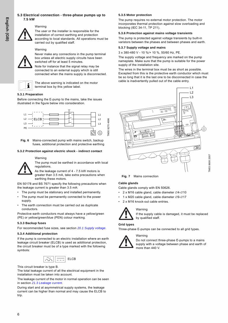
Before connecting the E-pump to the mains, take the issues illustrated in the figure below into consideration.
Fig. 6 Mains-connected pump with mains switch, backup fuses, additional protection and protective earthing
5.3.2 Protection against electric shock - indirect contact
EN 50178 and BS 7671 specify the following precautions when the leakage current is greater than 3.5 mA:
• The pump must be stationary and installed permanently.
• The pump must be permanently connected to the power supply.
• The earth connection must be carried out as duplicate conductors.
Protective earth conductors must always have a yellow/green (PE) or yellow/green/blue (PEN) colour marking.
5.3.3 Backup fuses
For recommended fuse sizes, see section 20.1 Supply voltage.
5.3.4 Additional protection
If the pump is connected to an electric installation where an earth leakage circuit breaker (ELCB) is used as additional protection, the circuit breaker must be of a type marked with the following symbols:
This circuit breaker is type B.The total leakage current of all the electrical equipment in the installation must be taken into account.
The leakage current of the motor in normal operation can be seen in section 21.3 Leakage current.
During start and at asymmetrical supply systems, the leakage current can be higher than normal and may cause the ELCB to trip.
5.3.5 Motor protection
The pump requires no external motor protection. The motor incorporates thermal protection against slow overloading and blocking (IEC 34-11, TP 211).
5.3.6 Protection against mains voltage transients
The pump is protected against voltage transients by built-in varistors between the phases and between phases and earth.
5.3.7 Supply voltage and mains
3 x 380-480 V - 10 %/+ 10 %, 50/60 Hz, PE.
The supply voltage and frequency are marked on the pump nameplate. Make sure that the pump is suitable for the power supply of the installation site.
The wires in the terminal box must be as short as possible. Excepted from this is the protective earth conductor which must be so long that it is the last one to be disconnected in case the cable is inadvertently pulled out of the cable entry.
Fig. 7 Mains connection
Cable glands
Cable glands comply with EN 50626.
• 2 x M16 cable gland, cable diameter ∅4-∅10
• 1 x M20 cable gland, cable diameter ∅9-∅17
• 2 x M16 knock-out cable entries.
Grid types
Three-phase E-pumps can be connected to all grid types.
Warning
The user or the installer is responsible for the installation of correct earthing and protection according to local standards. All operations must be carried out by qualified staff.
Warning
Never make any connections in the pump terminal box unless all electric supply circuits have been switched off for at least 5 minutes.
Note for instance that the signal relay may be connected to an external supply which is still connected when the mains supply is disconnected.
The above warning is indicated on the motor terminal box by this yellow label.
TM
00
92
70
46
96
Warning
The pump must be earthed in accordance with local regulations.
As the leakage current of 4 - 7.5 kW motors is greater than 3.5 mA, take extra precautions when earthing these motors.
L1
L2
L3
L2
L1
L3
PE
ELCB
ELCB
TM
03
86
00
20
07
Warning
If the supply cable is damaged, it must be replaced by qualified staff.
Warning
Do not connect three-phase E-pumps to a mains supply with a voltage between phase and earth of more than 440 V.
L1L2L3
L1
L2
L3
6
En
gli
sh
(G
B)
5.3.8 Start/stop of pump
When the pump is switched on via the mains, it will start after approx. 5 seconds.
If a higher number of starts and stops is desired, use the input for external start/stop when starting/stopping the pump.
When the pump is switched on via an external on/off switch, it will start immediately.
Automatic restart
However, automatic restart only applies to fault types set up to automatic restart. These faults could typically be one of these faults:
• temporary overload
• fault in the power supply.
5.3.9 Connections
As a precaution, the wires to be connected to the following connection groups must be separated from each other by reinforced insulation in their entire lengths:
Group 1: Inputs
• start/stop, terminals 2 and 3
• digital input, terminals 1 and 9
• setpoint input, terminals 4, 5 and 6
• sensor input, terminals 7 and 8
• GENIbus, terminals B, Y and A
All inputs (group 1) are internally separated from the mains-conducting parts by reinforced insulation and galvanically separated from other circuits.All control terminals are supplied with protective extra-low voltage (PELV), thus ensuring protection against electric shock.
Group 2: Output (relay signal, terminals NC, C, NO)
The output (group 2) is galvanically separated from other circuits. Therefore, the supply voltage or protective extra-low voltage can be connected to the output as desired.
Group 3: Mains supply (terminals N, PE, L)
Group 4: Communication cable (8-pin male socket) - only TPED
The communication cable is connected to the socket in group 4. The cable ensures communication between the two pumps, whether one or two pressure sensors are connected. See section 5.7 Communication cable for TPED pumps.The selector switch in group 4 enables changeover between the operating modes "alternating operation" and "standby operation". See the description in section 6.2.1 Additional operating modes - TPED pumps.
Fig. 8 Connection terminals TPE Series 2000
Caution The number of starts and stops via the mains voltage must not exceed four times per hour.
NoteIf a pump set up for automatic restart is stopped due to a fault, it will restart automatically when the fault has disappeared.
Note If no external on/off switch is connected, connect terminals 2 and 3 using a short wire.
TM
02
84
14
51
03
1 9 8 7 B Y A
0-10 V
0/4-20 mA 4-20 mA
1/0
NC C NO L1 L2 L3
10K
RUN
STOP
6 5 4 3 2
0/4-20 mA 0-10 V
1: Digital input 9: GND (frame)8: +24 V7: Sensor input
B: RS-485BY: ScreenA: RS-485A
6: GND (frame) 5: +10 V4: Setpoint input3: GND (frame)2: Start/stop
Gro
up
1
Gro
up
3
Gro
up
2
7
En
glis
h (G
B)
Fig. 9 Connection terminals TPED Series 2000
A galvanic separation must fulfil the requirements for reinforced insulation including creepage distances and clearances specified in EN 60335.
5.4 Electrical connection - three-phase pumps, 11-22 kW
5.4.1 Preparation
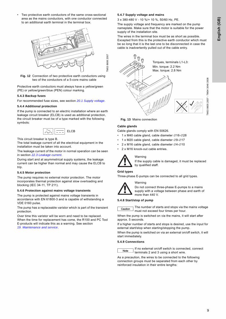
Before connecting the E-pump to the mains, take the issues illustrated in the figure below into consideration.
Fig. 10 Mains-connected pump with mains switch, backup fuses, additional protection and protective earthing
5.4.2 Protection against electric shock - indirect contact
EN 61800-5-1 specifies that the pump must be stationary and installed permanently when the leakage current is greater than 10 mA.
One of the following requirements must be fulfilled:
• A single protective earth conductor having a cross-sectional area of minimum 10 mm2.
Fig. 11 Connection of a single protective earth conductor using one of the conductors of a 4-core mains cable (with cross-sectional area of minimum 10 mm2)
TM
03
01
25
41
04
0/1
10K
RUN
STOP
1 9 8 7
6 5 4 3 2
B Y A
0-10 V0/4-20 mA 4-20 mA
0/4-20 mA 0-10 V
L3L2L1NOCNC
Gro
up
4
Gro
up
2
Gro
up
3
1: Digital input 9: GND (frame)8: +24 V7: Sensor input
B: RS-485BY: ScreenA: RS-485A
6: GND (frame) 5: +10 V4: Setpoint input3: GND (frame)2: Start/stop
Gro
up
1
Warning
The user or the installer is responsible for the installation of correct earthing and protection according to local standards. All operations must be carried out by qualified staff.
Warning
Never make any connections in the pump terminal box unless all electric supply circuits have been switched off for at least 5 minutes.
Note for instance that the signal relay may be connected to an external supply which is still connected when the mains supply is disconnected.
Warning
The surface of the terminal box may be above 70 °C when the pump is operating.
TM
00
92
70
46
96
Warning
The pump must be earthed in accordance with local regulations.
As the leakage current of 11-22 kW motors is greater than 10 mA, take extra precautions when earthing these motors.
TM
04
30
21
35
08
L1
L2
L3
L2
L1
L3
PE
ELCB
8
En
gli
sh
(G
B)
• Two protective earth conductors of the same cross-sectional area as the mains conductors, with one conductor connected to an additional earth terminal in the terminal box.
Fig. 12 Connection of two protective earth conductors using two of the conductors of a 5-core mains cable
Protective earth conductors must always have a yellow/green (PE) or yellow/green/blue (PEN) colour marking.
5.4.3 Backup fuses
For recommended fuse sizes, see section 20.1 Supply voltage.
5.4.4 Additional protection
If the pump is connected to an electric installation where an earth leakage circuit breaker (ELCB) is used as additional protection, the circuit breaker must be of a type marked with the following symbols:
This circuit breaker is type B.The total leakage current of all the electrical equipment in the installation must be taken into account.
The leakage current of the motor in normal operation can be seen in section 22.3 Leakage current.
During start and at asymmetrical supply systems, the leakage current can be higher than normal and may cause the ELCB to trip.
5.4.5 Motor protection
The pump requires no external motor protection. The motor incorporates thermal protection against slow overloading and blocking (IEC 34-11, TP 211).
5.4.6 Protection against mains voltage transients
The pump is protected against mains voltage transients in accordance with EN 61800-3 and is capable of withstanding a VDE 0160 pulse.
The pump has a replaceable varistor which is part of the transient protection.
Over time this varistor will be worn and need to be replaced. When the time for replacement has come, the R100 and PC Tool E-products will indicate this as a warning. See section 19. Maintenance and service.
5.4.7 Supply voltage and mains
3 x 380-480 V - 10 %/+ 10 %, 50/60 Hz, PE.
The supply voltage and frequency are marked on the pump nameplate. Make sure that the motor is suitable for the power supply of the installation site.
The wires in the terminal box must be as short as possible. Excepted from this is the protective earth conductor which must be so long that it is the last one to be disconnected in case the cable is inadvertently pulled out of the cable entry.
Fig. 13 Mains connection
Cable glands
Cable glands comply with EN 50626.
• 1 x M40 cable gland, cable diameter ∅16-∅28
• 1 x M20 cable gland, cable diameter ∅9-∅17
• 2 x M16 cable gland, cable diameter ∅4-∅10
• 2 x M16 knock-out cable entries.
Grid types
Three-phase E-pumps can be connected to all grid types.
5.4.8 Start/stop of pump
When the pump is switched on via the mains, it will start after approx. 5 seconds.
If a higher number of starts and stops is desired, use the input for external start/stop when starting/stopping the pump.
When the pump is switched on via an external on/off switch, it will start immediately.
5.4.9 Connections
As a precaution, the wires to be connected to the following connection groups must be separated from each other by reinforced insulation in their entire lengths:
TM
03
86
06
20
07
ELCB
TM
03
86
05
20
07
- T
M0
4 3
04
8 3
50
8
Warning
If the supply cable is damaged, it must be replaced by qualified staff.
Warning
Do not connect three-phase E-pumps to a mains supply with a voltage between phase and earth of more than 440 V.
Caution The number of starts and stops via the mains voltage must not exceed four times per hour.
NoteIf no external on/off switch is connected, connect terminals 2 and 3 using a short wire.
Torques, terminals L1-L3:
Min. torque: 2.2 NmMax. torque: 2.8 Nm
9

En
glis
h (G
B)
Group 1: Inputs
• start/stop, terminals 2 and 3
• digital input, terminals 1 and 9
• setpoint input, terminals 4, 5 and 6
• sensor input, terminals 7 and 8
• GENIbus, terminals B, Y and A
All inputs (group 1) are internally separated from the mains-conducting parts by reinforced insulation and galvanically separated from other circuits.All control terminals are supplied with protective extra-low voltage (PELV), thus ensuring protection against electric shock.
Group 2: Output (relay signal, terminals NC, C, NO)
The output (group 2) is galvanically separated from other circuits. Therefore, the supply voltage or protective extra-low voltage can be connected to the output as desired.
Group 3: Mains supply (terminals L1, L2, L3)
Group 4: Communication cable (8-pin male socket) - only TPED
The communication cable is connected to the socket in group 4. The cable ensures communication between the two pumps, whether one or two pressure sensors are connected. See section 5.7 Communication cable for TPED pumps.The selector switch in group 4 enables changeover between the operating modes "alternating operation" and "standby operation". See the description in section 6.2.1 Additional operating modes - TPED pumps.
Fig. 14 Connection terminals TPE Series 2000
Fig. 15 Connection terminals TPED Series 2000
A galvanic separation must fulfil the requirements for reinforced insulation including creepage distances and clearances specified in EN 61800-5-1.
TM
03
86
08
20
07
1: Digital input 9: GND (frame)8: +24 V7: Sensor input
B: RS-485BY: ScreenA: RS-485A
6: GND (frame) 5: +10 V4: Setpoint input3: GND (frame)2: Start/stop
Gro
up
1
Gro
up
2
Gro
up
3
TM
03
91
34
34
07
Group 4Group 2 Group 3
1: Digital input 9: GND (frame)8: +24 V7: Sensor input
B: RS-485BY: ScreenA: RS-485A
6: GND (frame) 5: +10 V4: Setpoint input3: GND (frame)2: Start/stop
Gro
up
1
10
En
gli
sh
(G
B)
5.5 Signal cables
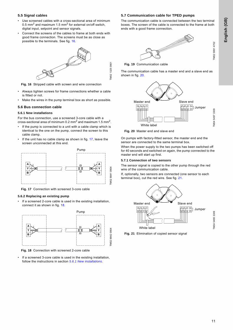
• Use screened cables with a cross-sectional area of minimum 0.5 mm2 and maximum 1.5 mm2 for external on/off switch, digital input, setpoint and sensor signals.
• Connect the screens of the cables to frame at both ends with good frame connection. The screens must be as close as possible to the terminals. See fig. 16.
Fig. 16 Stripped cable with screen and wire connection
• Always tighten screws for frame connections whether a cable is fitted or not.
• Make the wires in the pump terminal box as short as possible.
5.6 Bus connection cable
5.6.1 New installations
For the bus connection, use a screened 3-core cable with a cross-sectional area of minimum 0.2 mm2 and maximum 1.5 mm2.
• If the pump is connected to a unit with a cable clamp which is identical to the one on the pump, connect the screen to this cable clamp.
• If the unit has no cable clamp as shown in fig. 17, leave the screen unconnected at this end.
Fig. 17 Connection with screened 3-core cable
5.6.2 Replacing an existing pump
• If a screened 2-core cable is used in the existing installation, connect it as shown in fig. 18.
Fig. 18 Connection with screened 2-core cable
• If a screened 3-core cable is used in the existing installation, follow the instructions in section 5.6.1 New installations.
5.7 Communication cable for TPED pumps
The communication cable is connected between the two terminal boxes. The screen of the cable is connected to the frame at both ends with a good frame connection.
Fig. 19 Communication cable
The communication cable has a master end and a slave end as shown in fig. 20.
Fig. 20 Master end and slave end
On pumps with factory-fitted sensor, the master end and the sensor are connected to the same terminal box.
When the power supply to the two pumps has been switched off for 40 seconds and switched on again, the pump connected to the master end will start up first.
5.7.1 Connection of two sensors
The sensor signal is copied to the other pump through the red wire of the communication cable.
If, optionally, two sensors are connected (one sensor to each terminal box), cut the red wire. See fig. 21.
Fig. 21 Elimination of copied sensor signal
TM
02
13
25
09
01
TM
02
88
41
09
04
TM
02
88
42
09
04
A
Y
B
A
Y
B
123
123
Pump
A
Y
B
A
Y
B
1
2
1
2
PumpT
M0
2 5
99
1 4
70
2T
M0
4 5
49
7 3
30
9T
M0
4 5
49
5 3
30
9
Jumper
White label
Master end Slave end
Jumper
White label
Master end Slave end
11
En
glis
h (G
B)
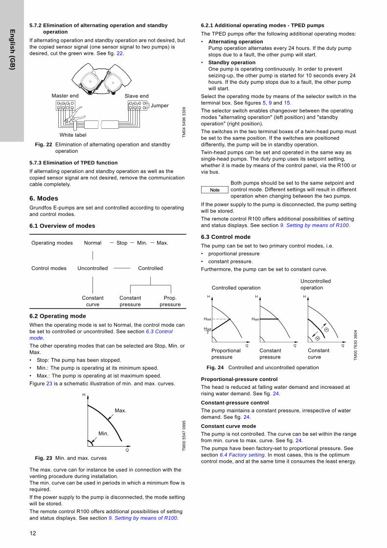
5.7.2 Elimination of alternating operation and standby operation
If alternating operation and standby operation are not desired, but the copied sensor signal (one sensor signal to two pumps) is desired, cut the green wire. See fig. 22.
Fig. 22 Elimination of alternating operation and standby operation
5.7.3 Elimination of TPED function
If alternating operation and standby operation as well as the copied sensor signal are not desired, remove the communication cable completely.
6. ModesGrundfos E-pumps are set and controlled according to operating and control modes.
6.1 Overview of modes
6.2 Operating mode
When the operating mode is set to Normal, the control mode can be set to controlled or uncontrolled. See section 6.3 Control mode.
The other operating modes that can be selected are Stop, Min. or Max.
• Stop: The pump has been stopped.
• Min.: The pump is operating at its minimum speed.
• Max.: The pump is operating at ist maximum speed.
Figure 23 is a schematic illustration of min. and max. curves.
Fig. 23 Min. and max. curves
The max. curve can for instance be used in connection with the venting procedure during installation.The min. curve can be used in periods in which a minimum flow is required.
If the power supply to the pump is disconnected, the mode setting will be stored.
The remote control R100 offers additional possibilities of setting and status displays. See section 9. Setting by means of R100.
6.2.1 Additional operating modes - TPED pumps
The TPED pumps offer the following additional operating modes:
• Alternating operationPump operation alternates every 24 hours. If the duty pump stops due to a fault, the other pump will start.
• Standby operationOne pump is operating continuously. In order to prevent seizing-up, the other pump is started for 10 seconds every 24 hours. If the duty pump stops due to a fault, the other pump will start.
Select the operating mode by means of the selector switch in the terminal box. See figures 5, 9 and 15.
The selector switch enables changeover between the operating modes "alternating operation" (left position) and "standby operation" (right position).
The switches in the two terminal boxes of a twin-head pump must be set to the same position. If the switches are positioned differently, the pump will be in standby operation.
Twin-head pumps can be set and operated in the same way as single-head pumps. The duty pump uses its setpoint setting, whether it is made by means of the control panel, via the R100 or via bus.
If the power supply to the pump is disconnected, the pump setting will be stored.
The remote control R100 offers additional possibilities of setting and status displays. See section 9. Setting by means of R100.
6.3 Control mode
The pump can be set to two primary control modes, i.e.
• proportional pressure
• constant pressure.
Furthermore, the pump can be set to constant curve.
Fig. 24 Controlled and uncontrolled operation
Proportional-pressure control
The head is reduced at falling water demand and increased at rising water demand. See fig. 24.
Constant-pressure control
The pump maintains a constant pressure, irrespective of water demand. See fig. 24.
Constant curve mode
The pump is not controlled. The curve can be set within the range from min. curve to max. curve. See fig. 24.
The pumps have been factory-set to proportional pressure. See section 6.4 Factory setting. In most cases, this is the optimum control mode, and at the same time it consumes the least energy.
TM
04
54
96
33
09
Operating modes Normal Stop Min. Max.
Control modes Uncontrolled Controlled
Constant curve
Constant pressure
Prop. pressure
TM
00
55
47
09
95
Jumper
White label
Master end Slave end
Q
H
Max.
Min.
NoteBoth pumps should be set to the same setpoint and control mode. Different settings will result in different operation when changing between the two pumps.
TM
00
76
30
36
042
setH
setH
H
Q
Hset
H
Q
H
Q
Controlled operationUncontrolled operation
Proportional pressure
Constant pressure
Constant curve
12
En
gli
sh
(G
B)
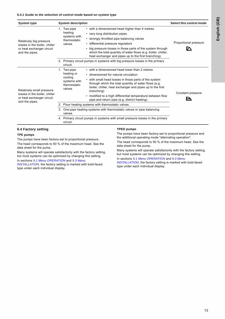
6.3.1 Guide to the selection of control mode based on system type
6.4 Factory setting
TPE pumps
The pumps have been factory-set to proportional pressure.
The head corresponds to 50 % of the maximum head. See the data sheet for the pump.
Many systems will operate satisfactorily with the factory setting, but most systems can be optimized by changing this setting.
In sections 9.1 Menu OPERATION and 9.3 Menu INSTALLATION, the factory setting is marked with bold-faced type under each individual display.
TPED pumps
The pumps have been factory-set to proportional pressure and the additional operating mode "alternating operation".
The head corresponds to 50 % of the maximum head. See the data sheet for the pump.
Many systems will operate satisfactorily with the factory setting, but most systems can be optimized by changing this setting.
In sections 9.1 Menu OPERATION and 9.3 Menu INSTALLATION, the factory setting is marked with bold-faced type under each individual display.
System type System description Select this control mode
Relatively big pressure losses in the boiler, chiller or heat exchanger circuit and the pipes.
1. Two-pipe heating systems with thermostatic valves
• with a dimensioned head higher than 4 metres
Proportional pressure
• very long distribution pipes
• strongly throttled pipe balancing valves
• differential pressure regulators
• big pressure losses in those parts of the system through which the total quantity of water flows (e.g. boiler, chiller, heat exchanger and pipes up to the first branching).
2. Primary circuit pumps in systems with big pressure losses in the primary circuit.
Relatively small pressure losses in the boiler, chiller or heat exchanger circuit and the pipes.
1. Two-pipe heating or cooling systems with thermostatic valves
• with a dimensioned head lower than 2 metres
Constant pressure
• dimensioned for natural circulation
• with small head losses in those parts of the system through which the total quantity of water flows (e.g. boiler, chiller, heat exchanger and pipes up to the first branching)
• modified to a high differential temperature between flow pipe and return pipe (e.g. district heating).
2. Floor heating systems with thermostatic valves.
3. One-pipe heating systems with thermostatic valves or pipe balancing valves.
4. Primary circuit pumps in systems with small pressure losses in the primary circuit.
13
En
glis
h (G
B)
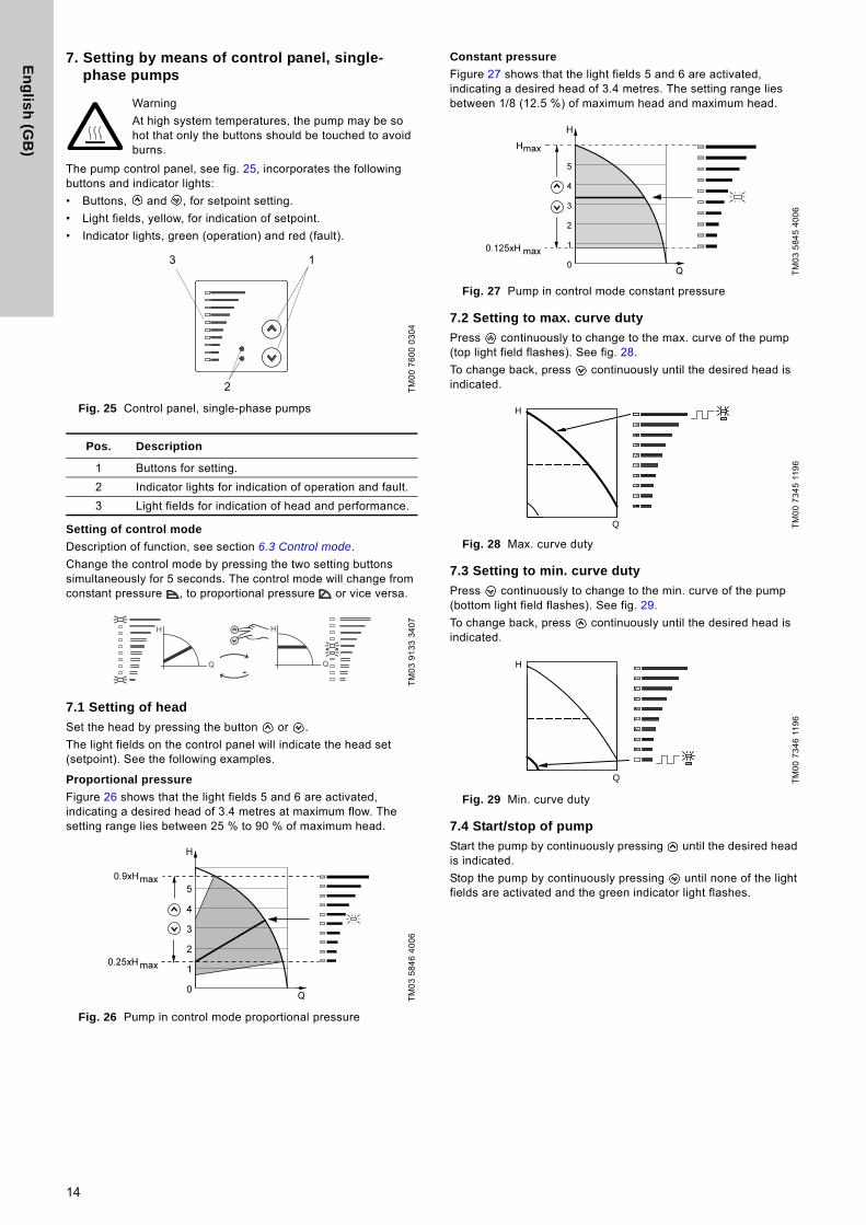
7. Setting by means of control panel, single-phase pumps
The pump control panel, see fig. 25, incorporates the following buttons and indicator lights:
• Buttons, and , for setpoint setting.
• Light fields, yellow, for indication of setpoint.
• Indicator lights, green (operation) and red (fault).
Fig. 25 Control panel, single-phase pumps
Setting of control mode
Description of function, see section 6.3 Control mode.
Change the control mode by pressing the two setting buttons simultaneously for 5 seconds. The control mode will change from constant pressure , to proportional pressure or vice versa.
7.1 Setting of head
Set the head by pressing the button or .
The light fields on the control panel will indicate the head set (setpoint). See the following examples.
Proportional pressure
Figure 26 shows that the light fields 5 and 6 are activated, indicating a desired head of 3.4 metres at maximum flow. The setting range lies between 25 % to 90 % of maximum head.
Fig. 26 Pump in control mode proportional pressure
Constant pressure
Figure 27 shows that the light fields 5 and 6 are activated, indicating a desired head of 3.4 metres. The setting range lies between 1/8 (12.5 %) of maximum head and maximum head.
Fig. 27 Pump in control mode constant pressure
7.2 Setting to max. curve duty
Press continuously to change to the max. curve of the pump (top light field flashes). See fig. 28.
To change back, press continuously until the desired head is indicated.
Fig. 28 Max. curve duty
7.3 Setting to min. curve duty
Press continuously to change to the min. curve of the pump (bottom light field flashes). See fig. 29.
To change back, press continuously until the desired head is indicated.
Fig. 29 Min. curve duty
7.4 Start/stop of pump
Start the pump by continuously pressing until the desired head is indicated.
Stop the pump by continuously pressing until none of the light fields are activated and the green indicator light flashes.
Warning
At high system temperatures, the pump may be so hot that only the buttons should be touched to avoid burns.
TM
00
76
00
03
04
Pos. Description
1 Buttons for setting.
2 Indicator lights for indication of operation and fault.
3 Light fields for indication of head and performance.
TM
03
91
33
34
07
TM
03
58
46
40
06
3 1
2
TM
03
58
45
40
06
TM
00
73
45
11
96
TM
00
73
46
11
96
H
Q
H
Q
14
En
gli
sh
(G
B)
8. Setting by means of control panel, three-phase pumps
The pump control panel incorporates the following buttons and indicator lights:
• Buttons, and , for setpoint setting.
• Light fields, yellow, for indication of setpoint.
• Indicator lights, green (operation) and red (fault).
Fig. 30 Control panel, three-phase pumps
8.1 Setting of control mode
Description of function, see section 6.3 Control mode.
Change the control mode by pressing (pos. 2) according to the following cycle:
• constant pressure,
• proportional pressure, .
8.2 Setting of head
Set the head by pressing the button or .
The light fields on the control panel will indicate the head set (setpoint). See the following examples.
Proportional pressure
Figure 31 shows that the light fields 5 and 6 are activated, indicating a desired head of 3.4 metres at maximum flow. The setting range lies between 25 % to 90 % of maximum head.
Fig. 31 Pump in control mode proportional pressure
Constant pressure
Figure 32 shows that the light fields 5 and 6 are activated, indicating a desired head of 3.4 metres. The setting range lies between 1/8 (12.5 %) of maximum head and maximum head.
Fig. 32 Pump in control mode constant-pressure
8.3 Setting to max. curve duty
Press continuously to change to the max. curve of the pump (MAX illuminates). See fig. 33.
To change back, press continuously until the desired head is indicated.
Fig. 33 Max. curve duty
Warning
At high system temperatures, the pump may be so hot that only the buttons should be touched to avoid burns.
TM
03
01
77
43
04
Pos. Description
1 and 2 Buttons for setting.
3 and 5Light fields for indication of • control mode (pos. 3)• head, performance and operating mode (pos. 5).
4Indicator lights for indication of• operation and fault• external control (EXT).
TM
03
90
61
33
07
15
4
3
2
TM
03
58
46
40
06
TM
03
58
45
40
06
TM
03
02
89
47
04
H
Q
15
En
glis
h (G
B)
8.4 Setting to min. curve duty
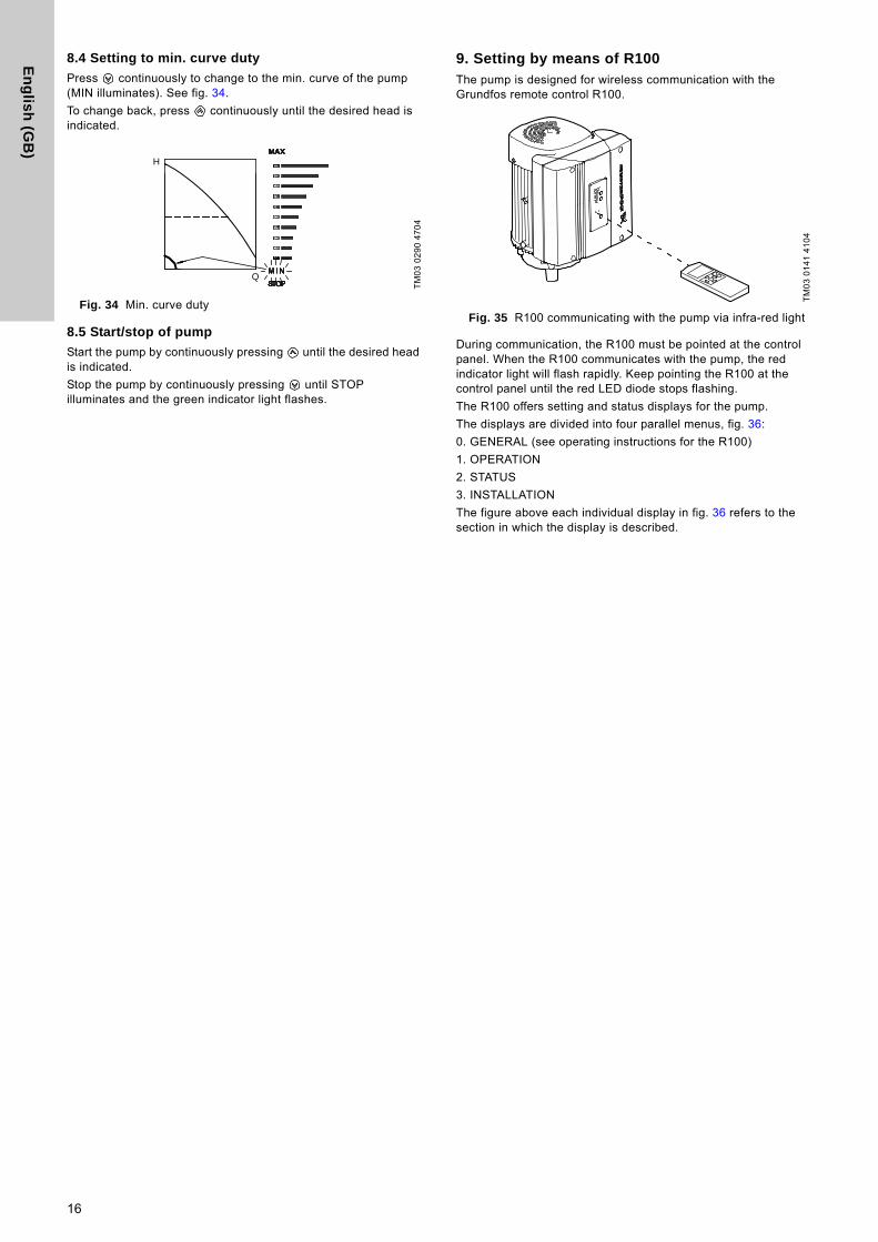
Press continuously to change to the min. curve of the pump (MIN illuminates). See fig. 34.
To change back, press continuously until the desired head is indicated.
Fig. 34 Min. curve duty
8.5 Start/stop of pump
Start the pump by continuously pressing until the desired head is indicated.
Stop the pump by continuously pressing until STOP illuminates and the green indicator light flashes.
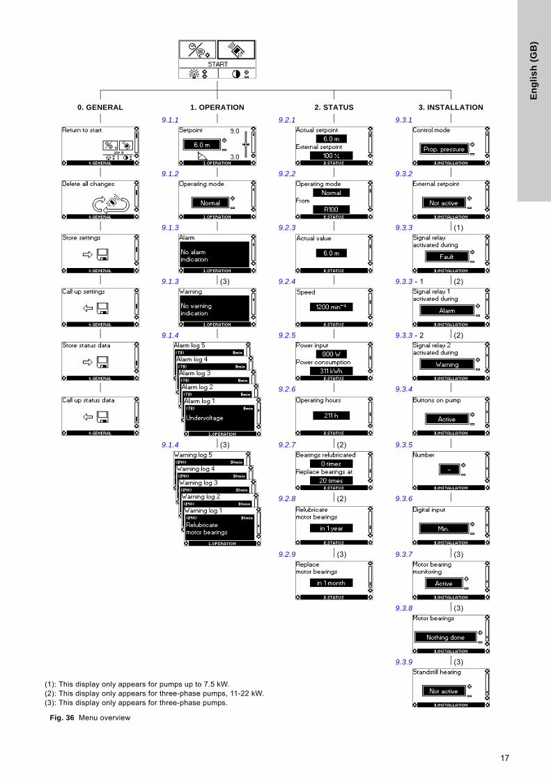
9. Setting by means of R100 The pump is designed for wireless communication with the Grundfos remote control R100.
Fig. 35 R100 communicating with the pump via infra-red light
During communication, the R100 must be pointed at the control panel. When the R100 communicates with the pump, the red indicator light will flash rapidly. Keep pointing the R100 at the control panel until the red LED diode stops flashing.
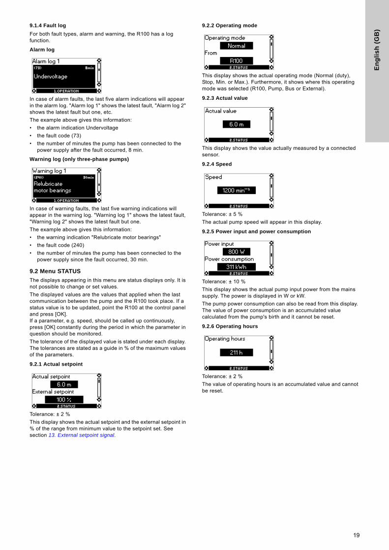
The R100 offers setting and status displays for the pump.
The displays are divided into four parallel menus, fig. 36:
0. GENERAL (see operating instructions for the R100)
1. OPERATION
2. STATUS
3. INSTALLATION
The figure above each individual display in fig. 36 refers to the section in which the display is described.
TM
03
02
90
47
04
H
Q
TM
03
01
41
41
04
16
En
gli
sh
(G
B)
Fig. 36 Menu overview
0. GENERAL 1. OPERATION 2. STATUS 3. INSTALLATION
9.1.1 9.2.1 9.3.1
9.1.2 9.2.2 9.3.2
9.1.3 9.2.3 9.3.3 (1)
9.1.3 (3) 9.2.4 9.3.3 - 1 (2)
9.1.4 9.2.5 9.3.3 - 2 (2)
9.2.6 9.3.4
9.1.4 (3) 9.2.7 (2) 9.3.5
9.2.8 (2) 9.3.6
9.2.9 (3) 9.3.7 (3)
9.3.8 (3)
9.3.9 (3)
(1): This display only appears for pumps up to 7.5 kW.(2): This display only appears for three-phase pumps, 11-22 kW.(3): This display only appears for three-phase pumps.
17

En
glis
h (G
B)
9.1 Menu OPERATION
The first display in this menu is this:
9.1.1 Setpoint
Setpoint set
Actual setpoint
Actual value
Set the desired setpoint in [m] in this display.
In control mode proportional pressure, the setting range is from 1/4 to 3/4 of maximum head.
In control mode constant pressure, the setting range is from 1/8 of maximum head to maximum head.
In control mode constant curve, the setpoint is set in % of the maximum curve. The curve can be set within the range from min. curve to max. curve.
Select one of the following operating modes:
• Stop
• Min. (min. curve)
• Max. (max. curve).
If the pump is connected to an external setpoint signal, the value in this display will be the maximum value of the external setpoint signal. See section 13. External setpoint signal.
Setpoint and external signal
The setpoint cannot be set if the pump is controlled via external signals (Stop, Min. curve or Max. curve). The R100 will give this warning: External control! Check if the pump is stopped via terminals 2-3 (open circuit) or set to min. or max. via terminals 1-3 (closed circuit).
See section 11. Priority of settings.
Setpoint and bus communication
The setpoint cannot be set either if the pump is controlled from an external control system via bus communication. The R100 will give this warning: Bus control! To override bus communication, disconnect the bus connection.
See section 11. Priority of settings.
9.1.2 Operating mode
Select one of the following operating modes:
• Normal (duty)
• Stop
• Min.
• Max.
The operating modes can be selected without changing the setpoint setting.
9.1.3 Fault indications
In E-pumps, faults may result in two types of indication: alarm or warning.
An alarm fault will activate an alarm indication in the R100 and cause the pump to change operating mode, typically to stop. However, for some faults resulting in alarm, the pump is set to continue operating even if there is an alarm.
A warning fault will activate a warning indication in the R100, but the pump will not change operating or control mode.
Alarm
In case of alarm, the cause will appear in this display.
Possible causes:
• No alarm indication
• Too high motor temperature
• Undervoltage
• Mains voltage asymmetry (11-22 kW)
• Overvoltage
• Too many restarts (after faults)
• Overload
• Underload (11-22 kW)
• Sensor signal outside signal range
• Setpoint signal outside signal range
• External fault
• Other fault.
If the pump has been set up to manual restart, an alarm indication can be reset in this display if the cause of the fault has disappeared.
Warning (only three-phase pumps)
In case of warning, the cause will appear in this display.
Possible causes:
• No warning indication
• Sensor signal outside signal range
• Relubricate motor bearings (only 11-22 kW). See section 19.2 Relubrication of motor bearings.
• Replace motor bearings, see section 19.3 Replacement of motor bearings
• Replace varistor (only 11-22 kW). See section 19.4 Replacement of varistor (only 11-22 kW).
A warning indication will disappear automatically once the fault has been remedied.
NoteThe indication "Warning" only applies to three-phase pumps.
18
En
gli
sh
(G
B)
9.1.4 Fault log
For both fault types, alarm and warning, the R100 has a log function.
Alarm log
In case of alarm faults, the last five alarm indications will appear in the alarm log. "Alarm log 1" shows the latest fault, "Alarm log 2" shows the latest fault but one, etc.
The example above gives this information:
• the alarm indication Undervoltage
• the fault code (73)
• the number of minutes the pump has been connected to the power supply after the fault occurred, 8 min.
Warning log (only three-phase pumps)
In case of warning faults, the last five warning indications will appear in the warning log. "Warning log 1" shows the latest fault, "Warning log 2" shows the latest fault but one.
The example above gives this information:
• the warning indication "Relubricate motor bearings"
• the fault code (240)
• the number of minutes the pump has been connected to the power supply since the fault occurred, 30 min.
9.2 Menu STATUS
The displays appearing in this menu are status displays only. It is not possible to change or set values.
The displayed values are the values that applied when the last communication between the pump and the R100 took place. If a status value is to be updated, point the R100 at the control panel and press [OK].If a parameter, e.g. speed, should be called up continuously, press [OK] constantly during the period in which the parameter in question should be monitored.
The tolerance of the displayed value is stated under each display. The tolerances are stated as a guide in % of the maximum values of the parameters.
9.2.1 Actual setpoint
Tolerance: ± 2 %
This display shows the actual setpoint and the external setpoint in % of the range from minimum value to the setpoint set. See section 13. External setpoint signal.
9.2.2 Operating mode
This display shows the actual operating mode (Normal (duty), Stop, Min. or Max.). Furthermore, it shows where this operating mode was selected (R100, Pump, Bus or External).
9.2.3 Actual value
This display shows the value actually measured by a connected sensor.
9.2.4 Speed
Tolerance: ± 5 %
The actual pump speed will appear in this display.
9.2.5 Power input and power consumption
Tolerance: ± 10 %
This display shows the actual pump input power from the mains supply. The power is displayed in W or kW.
The pump power consumption can also be read from this display. The value of power consumption is an accumulated value calculated from the pump's birth and it cannot be reset.
9.2.6 Operating hours
Tolerance: ± 2 %
The value of operating hours is an accumulated value and cannot be reset.
19
En
glis
h (G
B)
9.2.7 Lubrication status of motor bearings (only 11-22 kW)
This display shows how many times the motor bearings have been relubricated and when to replace the motor bearings.
When the motor bearings have been relubricated, confirm this action in the INSTALLATION menu. See section 9.3.8 Confirming relubrication/replacement of motor bearings (only three-phase pumps). When relubrication is confirmed, the figure in the above display will be increased by one.
9.2.8 Time till relubrication of motor bearings (only 11-22 kW)
This display shows when to relubricate the motor bearings. The controller monitors the operating pattern of the pump and calculates the period between bearing relubrications. If the operating pattern changes, the calculated time till relubrication may change as well.
The displayable values are these:
• in 2 years
• in 1 year
• in 6 months
• in 3 months
• in 1 month
• in 1 week
• Now!
9.2.9 Time till replacement of motor bearings (only three-phase pumps)
When the motor bearings have been relubricated, a prescribed number of times stored in the controller, the display in section 9.2.8 Time till relubrication of motor bearings (only 11-22 kW) will be replaced by the display below.
This display shows when to replace the motor bearings. The controller monitors the operating pattern of the pump and calculates the period between bearing replacements.
The displayable values are these:
• in 2 years
• in 1 year
• in 6 months
• in 3 months
• in 1 month
• in 1 week
• Now!
9.3 Menu INSTALLATION
9.3.1 Control mode
Select one of the following control modes (see fig. 24):
• Prop. pressure (proportional pressure)
• Const. pressure (constant pressure)
• Const. curve (constant curve).
How to set the desired performance, see section 9.1.1 Setpoint.
9.3.2 External setpoint
The input for external setpoint signal can be set to different signal types.
Select one of the following types:
• 0-10 V
• 0-20 mA
• 4-20 mA
• Not active.
If "Not active" is selected, the setpoint set by means of the R100 or on the control panel will apply.
If one of the signal types is selected, the actual setpoint is influenced by the signal connected to the external setpoint input. See section 13. External setpoint signal.
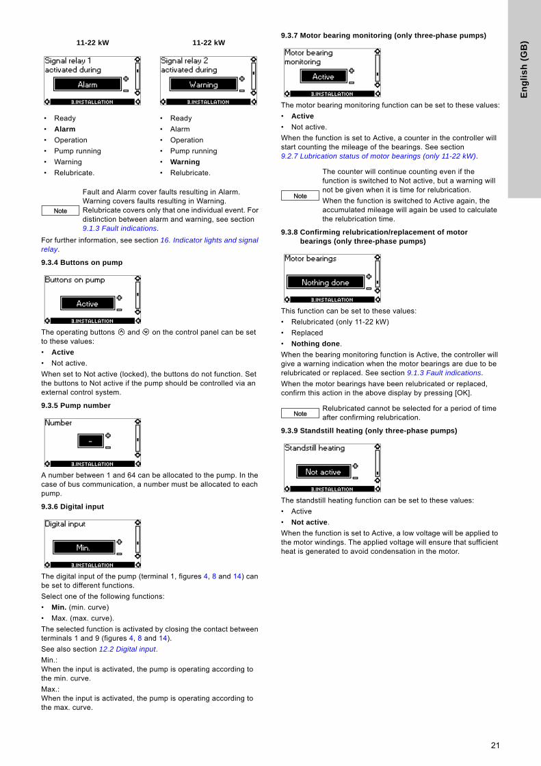
9.3.3 Signal relay
Pumps up to 7.5 kW have one signal relay. The factory setting of the relay will be Fault.
Pumps of 11-22 kW have two signal relays. Signal relay 1 is factory-set to Alarm and signal relay 2 to Warning.
In one of the displays below, select in which operating situation the signal relay should be activated.
For further information, see section 16. Indicator lights and signal relay.
NoteIf the pump is connected to a bus, the control mode cannot be selected via the R100. See section 14. Bus signal.
Up to 7.5 kW
• Ready
• Fault
• Operation
• Pump running (only three-phase pumps up to 7.5 kW)
• Warning (only three-phase pumps up to 7.5 kW).
20
En
gli
sh
(G
B)
For further information, see section 16. Indicator lights and signal relay.
9.3.4 Buttons on pump
The operating buttons and on the control panel can be set to these values:
• Active
• Not active.
When set to Not active (locked), the buttons do not function. Set the buttons to Not active if the pump should be controlled via an external control system.
9.3.5 Pump number
A number between 1 and 64 can be allocated to the pump. In the case of bus communication, a number must be allocated to each pump.
9.3.6 Digital input
The digital input of the pump (terminal 1, figures 4, 8 and 14) can be set to different functions.
Select one of the following functions:
• Min. (min. curve)
• Max. (max. curve).
The selected function is activated by closing the contact between terminals 1 and 9 (figures 4, 8 and 14).
See also section 12.2 Digital input.
Min.: When the input is activated, the pump is operating according to the min. curve.
Max.: When the input is activated, the pump is operating according to the max. curve.
9.3.7 Motor bearing monitoring (only three-phase pumps)
The motor bearing monitoring function can be set to these values:
• Active
• Not active.
When the function is set to Active, a counter in the controller will start counting the mileage of the bearings. See section 9.2.7 Lubrication status of motor bearings (only 11-22 kW).
9.3.8 Confirming relubrication/replacement of motor bearings (only three-phase pumps)
This function can be set to these values:
• Relubricated (only 11-22 kW)
• Replaced
• Nothing done.
When the bearing monitoring function is Active, the controller will give a warning indication when the motor bearings are due to be relubricated or replaced. See section 9.1.3 Fault indications.
When the motor bearings have been relubricated or replaced, confirm this action in the above display by pressing [OK].
9.3.9 Standstill heating (only three-phase pumps)
The standstill heating function can be set to these values:
• Active
• Not active.
When the function is set to Active, a low voltage will be applied to the motor windings. The applied voltage will ensure that sufficient heat is generated to avoid condensation in the motor.
11-22 kW 11-22 kW
• Ready
• Alarm
• Operation
• Pump running
• Warning
• Relubricate.
• Ready
• Alarm
• Operation
• Pump running
• Warning
• Relubricate.
Note
Fault and Alarm cover faults resulting in Alarm. Warning covers faults resulting in Warning.Relubricate covers only that one individual event. For distinction between alarm and warning, see section 9.1.3 Fault indications.
Note
The counter will continue counting even if the function is switched to Not active, but a warning will not be given when it is time for relubrication.
When the function is switched to Active again, the accumulated mileage will again be used to calculate the relubrication time.
NoteRelubricated cannot be selected for a period of time after confirming relubrication.
21
En
glis
h (G
B)
10. Setting by means of PC Tool E-productsSpecial setup requirements differing from the settings available via the R100 require the use of Grundfos PC Tool E-products. This again requires the assistance of a Grundfos service technician or engineer. Contact your local Grundfos company for more information.
11. Priority of settings The priority of settings depends on two factors:
1. control source
2. settings.
2. Settings
• Operating mode "Stop"
• Operating mode "Max." (max. curve)
• Operating mode "Min." (min. curve)
• Setpoint setting.
An E-pump can be controlled by different control sources at the same time, and each of these sources can be set differently. Consequently, it is necessary to set an order of priority of the control sources and the settings.
Priority of settings without bus communication
Example: If the E-pump has been set to operating mode Max. (max. frequency) via an external signal, such as digital input, the control panel or R100 can only set the E-pump to operating mode Stop.
Priority of settings with bus communication
Example: If the E-pump is operating according to a setpoint set via bus communication, the control panel or R100 can set the E-pump to operating mode Stop or Max., and the external signal can only set the E-pump to operating mode Stop.
12. External forced-control signals The pump has inputs for external signals for the forced-control functions:
• Start/stop of pump.
• Digital function.
12.1 Start/stop input
Functional diagram: Start/stop input
12.2 Digital input
By means of the R100, one of the following functions can be selected for the digital input:
• Min. curve
• Max. curve.
Functional diagram: Input for digital function
1. Control source
Control panel
R100
External signals (external setpoint signal, digital inputs, etc.)
Communication from another control system via bus
NoteIf two or more settings are activated at the same time, the pump will operate according to the function with the highest priority.
Priority Control panel or R100 External signals
1 Stop
2 Max.
3 Stop
4 Max.
5 Min. Min.
6 Setpoint setting Setpoint setting
PriorityControl panel
or R100External signals
Bus communication
1 Stop
2 Max.
3 Stop Stop
4 Max.
5 Min.
6 Setpoint setting
Start/stop (terminals 2 and 3)
Normal duty
Stop
Digital function (terminals 1 and 9)
Normal duty
Min. curve
Max. curve
Q
H
Q
H
Q
H
Q
H
Q
H
22
En
gli
sh
(G
B)
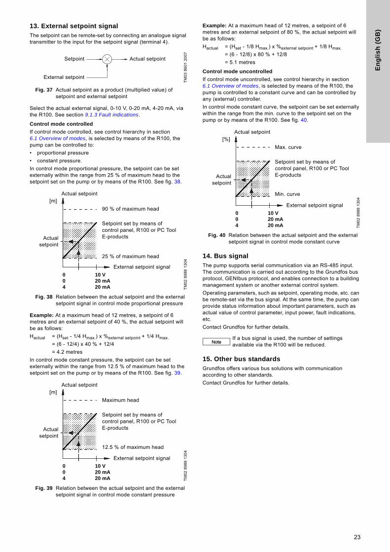
13. External setpoint signalThe setpoint can be remote-set by connecting an analogue signal transmitter to the input for the setpoint signal (terminal 4).
Fig. 37 Actual setpoint as a product (multiplied value) of setpoint and external setpoint
Select the actual external signal, 0-10 V, 0-20 mA, 4-20 mA, via the R100. See section 9.1.3 Fault indications.
Control mode controlled
If control mode controlled, see control hierarchy in section 6.1 Overview of modes, is selected by means of the R100, the pump can be controlled to:
• proportional pressure
• constant pressure.
In control mode proportional pressure, the setpoint can be set externally within the range from 25 % of maximum head to the setpoint set on the pump or by means of the R100. See fig. 38.
Fig. 38 Relation between the actual setpoint and the external setpoint signal in control mode proportional pressure
Example: At a maximum head of 12 metres, a setpoint of 6 metres and an external setpoint of 40 %, the actual setpoint will be as follows:
Hactual = (Hset - 1/4 Hmax.) x %external setpoint + 1/4 Hmax.
= (6 - 12/4) x 40 % + 12/4
= 4.2 metres
In control mode constant pressure, the setpoint can be set externally within the range from 12.5 % of maximum head to the setpoint set on the pump or by means of the R100. See fig. 39.
Fig. 39 Relation between the actual setpoint and the external setpoint signal in control mode constant pressure
Example: At a maximum head of 12 metres, a setpoint of 6 metres and an external setpoint of 80 %, the actual setpoint will be as follows:
Hactual = (Hset - 1/8 Hmax.) x %external setpoint + 1/8 Hmax.
= (6 - 12/8) x 80 % + 12/8
= 5.1 metres
Control mode uncontrolled
If control mode uncontrolled, see control hierarchy in section 6.1 Overview of modes, is selected by means of the R100, the pump is controlled to a constant curve and can be controlled by any (external) controller.
In control mode constant curve, the setpoint can be set externally within the range from the min. curve to the setpoint set on the pump or by means of the R100. See fig. 40.
Fig. 40 Relation between the actual setpoint and the external setpoint signal in control mode constant curve
14. Bus signal The pump supports serial communication via an RS-485 input. The communication is carried out according to the Grundfos bus protocol, GENIbus protocol, and enables connection to a building management system or another external control system.
Operating parameters, such as setpoint, operating mode, etc. can be remote-set via the bus signal. At the same time, the pump can provide status information about important parameters, such as actual value of control parameter, input power, fault indications, etc.
Contact Grundfos for further details.
15. Other bus standards Grundfos offers various bus solutions with communication according to other standards.
Contact Grundfos for further details.
TM
03
86
01
20
07
TM
02
89
88
13
04
TM
02
89
88
13
04
Setpoint
External setpoint
Actual setpoint
0 10 V0 20 mA4 20 mA
Actual setpoint
90 % of maximum head
Setpoint set by means of control panel, R100 or PC Tool E-products
25 % of maximum head
External setpoint signal
Actualsetpoint
[m]
0 10 V0 20 mA4 20 mA
Actual setpoint
Maximum head
Setpoint set by means of control panel, R100 or PC Tool E-products
12.5 % of maximum head
External setpoint signal
Actualsetpoint
[m]
TM
02
89
88
13
04
NoteIf a bus signal is used, the number of settings available via the R100 will be reduced.
0 10 V0 20 mA4 20 mA
Actual setpoint
Max. curve
Setpoint set by means of control panel, R100 or PC Tool E-products
Min. curve
External setpoint signal
Actualsetpoint
[%]
23
En
glis
h (G
B)
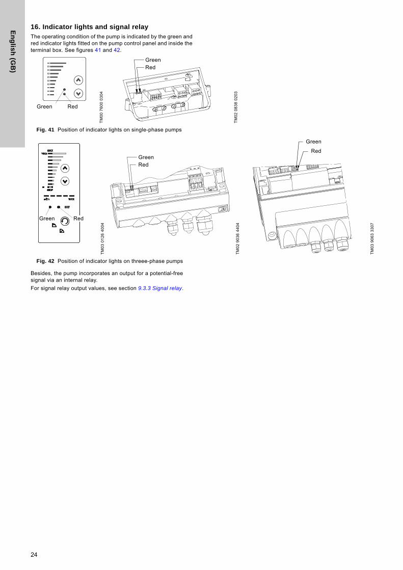
16. Indicator lights and signal relay The operating condition of the pump is indicated by the green and red indicator lights fitted on the pump control panel and inside the terminal box. See figures 41 and 42.
Fig. 41 Position of indicator lights on single-phase pumps
Fig. 42 Position of indicator lights on threee-phase pumps
Besides, the pump incorporates an output for a potential-free signal via an internal relay.
For signal relay output values, see section 9.3.3 Signal relay.
TM
00
76
00
03
04
TM
02
08
38
02
03
Green Red
GreenRed
TM
03
01
26
40
04
TM
02
90
36
44
04
TM
03
90
63
33
07
Green Red
GreenRed
Green
Red
24
En
gli
sh
(G
B)
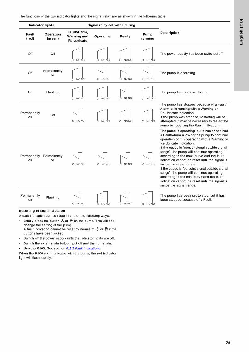
The functions of the two indicator lights and the signal relay are as shown in the following table:
Resetting of fault indication
A fault indication can be reset in one of the following ways:
• Briefly press the button or on the pump. This will not change the setting of the pump. A fault indication cannot be reset by means of or if the buttons have been locked.
• Switch off the power supply until the indicator lights are off.
• Switch the external start/stop input off and then on again.
• Use the R100. See section 9.1.3 Fault indications.
When the R100 communicates with the pump, the red indicator light will flash rapidly.
Indicator lights Signal relay activated during
DescriptionFault(red)
Operation (green)
Fault/Alarm, Warning and Relubricate
Operating ReadyPump
running
Off Off The power supply has been switched off.
OffPermanently
onThe pump is operating.
Off Flashing The pump has been set to stop.
Permanently on
Off
The pump has stopped because of a Fault/Alarm or is running with a Warning or Relubricate indication.If the pump was stopped, restarting will be attempted (it may be necessary to restart the pump by resetting the Fault indication).
Permanently on
Permanently on
The pump is operating, but it has or has had a Fault/Alarm allowing the pump to continue operation or it is operating with a Warning or Relubricate indication.If the cause is "sensor signal outside signal range", the pump will continue operating according to the max. curve and the fault indication cannot be reset until the signal is inside the signal range.If the cause is "setpoint signal outside signal range", the pump will continue operating according to the min. curve and the fault indication cannot be reset until the signal is inside the signal range.
Permanently on
FlashingThe pump has been set to stop, but it has been stopped because of a Fault.
NCNOC NCNOC NCNOC NCNOC
NCNOC C NO NC C NO NC C NO NC
NCNOC NCNOC C NO NC NCNOC
C NO NC NCNOC NCNOC NCNOC
C NO NC C NO NC C NO NC C NO NC
C NO NC NCNOC C NO NC NCNOC
25
En
glis
h (G
B)
17. Insulation resistance
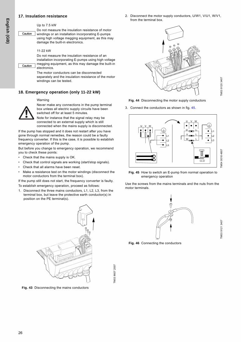
18. Emergency operation (only 11-22 kW)
If the pump has stopped and it does not restart after you have gone through normal remedies, the reason could be a faulty frequency converter. If this is the case, it is possible to establish emergency operation of the pump.
But before you change to emergency operation, we recommend you to check these points:
• Check that the mains supply is OK.
• Check that control signals are working (start/stop signals).
• Check that all alarms have been reset.
• Make a resistance test on the motor windings (disconnect the motor conductors from the terminal box).
If the pump still does not start, the frequency converter is faulty.
To establish emergency operation, proceed as follows:
1. Disconnect the three mains conductors, L1, L2, L3, from the terminal box, but leave the protective earth conductor(s) in position on the PE terminal(s).
Fig. 43 Disconnecting the mains conductors
2. Disconnect the motor supply conductors, U/W1, V/U1, W/V1, from the terminal box.
Fig. 44 Disconnecting the motor supply conductors
3. Connect the conductors as shown in fig. 45.
Fig. 45 How to switch an E-pump from normal operation to emergency operation
Use the screws from the mains terminals and the nuts from the motor terminals.
Fig. 46 Connecting the conductors
Caution
Up to 7.5 kW
Do not measure the insulation resistance of motor windings or an installation incorporating E-pumps using high voltage megging equipment, as this may damage the built-in electronics.
Caution
11-22 kW
Do not measure the insulation resistance of an installation incorporating E-pumps using high voltage megging equipment, as this may damage the built-in electronics.
The motor conductors can be disconnected separately and the insulation resistance of the motor windings can be tested.
Warning
Never make any connections in the pump terminal box unless all electric supply circuits have been switched off for at least 5 minutes.
Note for instance that the signal relay may be connected to an external supply which is still connected when the mains supply is disconnected.
TM
03
86
07
20
07
TM
03
91
20
34
07
TM
04
00
18
48
07
TM
03
91
21
34
07
26

En
gli
sh
(G
B)
4. Insulate the three conductors from each other by means of insulating tape or the like.
Fig. 47 Insulating the conductors
Fig. 48 Insulated conductors
19. Maintenance and service
19.1 Cleaning of the motor
Keep the motor cooling fins and fan blades clean to ensure sufficient cooling of the motor and electronics.
19.2 Relubrication of motor bearings
Pumps up to 7.5 kW
The motor bearings are of the closed type and greased for life. The bearings cannot be relubricated.
Pumps of 11-22 kW
The motor bearings are of the open type and must be relubricated regularly.The motor bearings are pre-lubricated on delivery. The built-in bearing monitoring function will give a warning indication on the R100 when the motor bearings are due to be relubricated.
When relubricating the first time, use the double quantity of grease as the lubricating channel is still empty.
The recommended grease type is a polycarbamide-based lubricating grease.
19.3 Replacement of motor bearings
Three-phase motors have built-in bearing monitoring function which will give a warning indication on the R100 when the motor bearings are due to be replaced.
19.4 Replacement of varistor (only 11-22 kW)
The varistor protects the pump against mains voltage transients. If voltage transients occur, the varistor will be worn over time and need to be replaced. The more transients, the more quickly the varistor will be worn. When it is time to replace the varistor, R100 and PC Tool E-products will indicate this as a warning.
A Grundfos technician is required for replacement of the varistor. Contact your local Grundfos company for assistance.
19.5 Service parts and service kits
For further information on service parts and service kits, visit www.grundfos.com, select country, select Grundfos Product Center.
TM
03
91
22
34
07
TM
03
91
23
34
07
Warning
Do not bypass the frequency converter by connecting the mains conductors to the U, V and W terminals.
This may cause hazardous situations for staff as the high voltage potential of the mains may be transferred to touchable components in the terminal box.
Caution Check the direction of rotation when starting up after switching to emergency operation.
NoteBefore relubrication, remove the bottom plug in the motor flange and the plug in the bearing cover to ensure that old and excess grease can escape.
Frame size
Quantity of grease[ml]
Drive end Non-drive end
MGE 160 13 13
MGE 180 15 15
27
En
glis
h (G
B)
20. Technical data - single-phase pumps
20.1 Supply voltage
1 x 200-240 V - 10 %/+ 10 %, 50/60 Hz - 2 %/+ 2 %, PE.
Recommended fuse size
Motor sizes up to 1.1 kW: Max. 10 A.
Standard as well as quick-blow or slow-blow fuses may be used.
20.2 Overload protection
The overload protection of the E-motor has the same characteristic as an ordinary motor protector. As an example, the E-motor can stand an overload of 110 % of Inom for 1 min.
20.3 Leakage current
The earth leakage current is less than 3.5 mA.
The leakage currents are measured in accordance with EN 61800-5-1.
20.4 Inputs/outputs
Start/stop
External potential-free switch. Voltage: 5 VDC. Current: < 5 mA.Screened cable: 0.5 - 1.5 mm2 / 28-16 AWG.
Digital
External potential-free switch. Voltage: 5 VDC. Current: < 5 mA.Screened cable: 0.5 - 1.5 mm2 / 28-16 AWG.
Setpoint signals
• Potentiometer0-10 VDC, 10 kΩ (via internal voltage supply).Screened cable: 0.5 - 1.5 mm2 / 28-16 AWG.Maximum cable length: 100 m.
• Voltage signal0-10 VDC, Ri > 50 kΩ.Tolerance: + 0 %/- 3 % at maximum voltage signal. Screened cable: 0.5 - 1.5 mm2 / 28-16 AWG.Maximum cable length: 500 m.
• Current signalDC 0-20 mA/4-20 mA, Ri = 175 Ω.Tolerance: + 0 %/- 3 % at maximum current signal. Screened cable: 0.5 - 1.5 mm2 / 28-16 AWG.Maximum cable length: 500 m.
Signal relay output
Potential-free changeover contact.Maximum contact load: 250 VAC, 2 A, cos 0.3 - 1. Minimum contact load: 5 VDC, 10 mA.Screened cable: 0.5 - 2.5 mm2 / 28-12 AWG.Maximum cable length: 500 m.
Bus input
Grundfos bus protocol, GENIbus protocol, RS-485. Screened 3-core cable: 0.2 - 1.5 mm2 / 28-16 AWG.Maximum cable length: 500 m.
21. Technical data - three-phase pumps up to 7.5 kW
21.1 Supply voltage
3 x 380-480 V - 10 %/+ 10 %, 50/60 Hz - 2 %/+ 2 %, PE.
Recommended fuse sizes
Motor sizes from 0.55 to 5.5 kW: Max. 16 A.Motor size 7.5 kW: Max. 32 A.
Standard as well as quick-blow or slow-blow fuses may be used.
21.2 Overload protection
The overload protection of the E-motor has the same characteristic as an ordinary motor protector. As an example, the E-motor can stand an overload of 110 % of Inom for 1 min.
21.3 Leakage current
The leakage currents are measured in accordance with EN 61800-5-1.
21.4 Inputs/output
Start/stop
External potential-free switch. Voltage: 5 VDC. Current: < 5 mA.Screened cable: 0.5 - 1.5 mm2 / 28-16 AWG.
Digital
External potential-free switch. Voltage: 5 VDC. Current: < 5 mA.Screened cable: 0.5 - 1.5 mm2 / 28-16 AWG.
Setpoint signals
• Potentiometer0-10 VDC, 10 kΩ (via internal voltage supply).Screened cable: 0.5 - 1.5 mm2 / 28-16 AWG.Maximum cable length: 100 m.
• Voltage signal0-10 VDC, Ri > 50 kΩ. Tolerance: + 0 %/- 3 % at maximum voltage signal. Screened cable: 0.5 - 1.5 mm2 / 28-16 AWG.Maximum cable length: 500 m.
• Current signalDC 0-20 mA/4-20 mA, Ri = 175 Ω.Tolerance: + 0 %/- 3 % at maximum current signal. Screened cable: 0.5 - 1.5 mm2 / 28-16 AWG.Maximum cable length: 500 m.
Signal relay output
Potential-free changeover contact.Maximum contact load: 250 VAC, 2 A, cos φ 0.3 - 1. Minimum contact load: 5 VDC, 10 mA.Screened cable: 0.5 - 2.5 mm2 / 28-12 AWG.Maximum cable length: 500 m.
Bus input
Grundfos bus protocol, GENIbus protocol, RS-485. Screened 3-core cable: 0.2 - 1.5 mm2 / 28-16 AWG.Maximum cable length: 500 m.
Motor size[kW]
Leakage current[mA]
0.55 to 3.0 (supply voltage < 460 V)0.55 to 3.0 (supply voltage > 460 V)
< 3.5< 5
4.0 - 5.5 < 5
7.5 < 10
28

En
gli
sh
(G
B)
22. Technical data - three-phase pumps, 11-22kW
22.1 Supply voltage
3 x 380-480 V - 10 %/+ 10 %, 50/60 Hz - 3 %/+ 3 %, PE.
Recommended fuse sizes
Standard as well as quick-blow or slow-blow fuses may be used.
22.2 Overload protection
The overload protection of the E-motor has the same characteristic as an ordinary motor protector. As an example, the E-motor can stand an overload of 110 % of Inom for 1 min.
22.3 Leakage current
The earth leakage current is greater than 10 mA.
The leakage currents are measured in accordance with EN 61800-5-1.
22.4 Inputs/output
Start/stop
External potential-free switch. Voltage: 5 VDC.Current: < 5 mA.Screened cable: 0.5 - 1.5 mm2 / 28-16 AWG.
Digital
External potential-free switch. Voltage: 5 VDC. Current: < 5 mA.Screened cable: 0.5 - 1.5 mm2 / 28-16 AWG.
Setpoint signals
• Potentiometer0-10 VDC, 10 kΩ (via internal voltage supply).Screened cable: 0.5 - 1.5 mm2 / 28-16 AWG.Maximum cable length: 100 m.
• Voltage signal0-10 VDC, Ri > 50 kΩ. Tolerance: + 0 %/- 3 % at maximum voltage signal. Screened cable: 0.5 - 1.5 mm2 / 28-16 AWG.Maximum cable length: 500 m.
• Current signalDC 0-20 mA/4-20 mA, Ri = 250 Ω.Tolerance: + 0 %/- 3 % at maximum current signal. Screened cable: 0.5 - 1.5 mm2 / 28-16 AWG.Maximum cable length: 500 m.
Signal relay output
Potential-free changeover contact.Maximum contact load: 250 VAC, 2 A, cos φ 0.3 - 1.Minimum contact load: 5 VDC, 10 mA.Screened cable: 0.5 - 2.5 mm2 / 28-12 AWG.Maximum cable length: 500 m.
Bus input
Grundfos bus protocol, GENIbus protocol, RS-485. Screened 3-core cable: 0.2 - 1.5 mm2 / 28-16 AWG.Maximum cable length: 500 m.
23. Other technical data
EMC (electromagnetic compatibility to EN 61800-3)
Contact Grundfos for further information.
Motor size [kW] Max. [A]
2-pole 4-pole
11 11 32
15 15 36
18.5 18.5 43
22 22 51
Motor [kW]Emission/immunity
2-pole 4-pole
- 0.12
EmissionMotors may be installed in residential areas (first environment), unrestricted distribution, corresponding to CISPR11, group 1, class B.
ImmunityMotors fulfil the requirements for both the first and second environment.
0.18 0.18
0.25 0.25
0.37 0.37
0.55 0.55
0.75 0.75
1.1 1.1
1.5 1.5
2.2 2.2
3.0 3.0
4.0 4.0
5.5 -
7.5 -
- 5.5 EmissionThe motors are category C3, corresponding to CISPR11, group 2, class A, and may be installed in industrial areas (second environment).If equipped with an external Grundfos EMC filter, the motors are category C2, corresponding to CISPR11, group 1, class A, and may be installed in residential areas (first environment).
- 7.5
11 11
15 15
18.5 18.5
22 -
Warning
When the motors are installed in residential areas, supplementary measures may be required as the motors may cause radio interference.
Motor sizes 11, 18.5 and 22 kW comply with EN 61000-3-12 provided that the short-circuit power at the interface point between the user's electrical installation and the public power supply network is greater than or equal to the values stated below. It is the responsibility of the installer or user to ensure, by consultation with the power supply network operator, if necessary, that the motor is connected to a power supply with a short-circuit power greater than or equal to these values:
Motor size[kW]
Short-circuit power[kVA]
11 1500
15 -
18.5 2700
22 3000
Note15 kW motors do not comply with EN 61000-3-12.
By installing an appropriate harmonic filter between the motor and the power supply, the harmonic current content will be reduced. In this way the 15 kW motor will comply with EN 61000-3-12.
ImmunityThe motors fulfil the requirements for both the first and second environment.
29
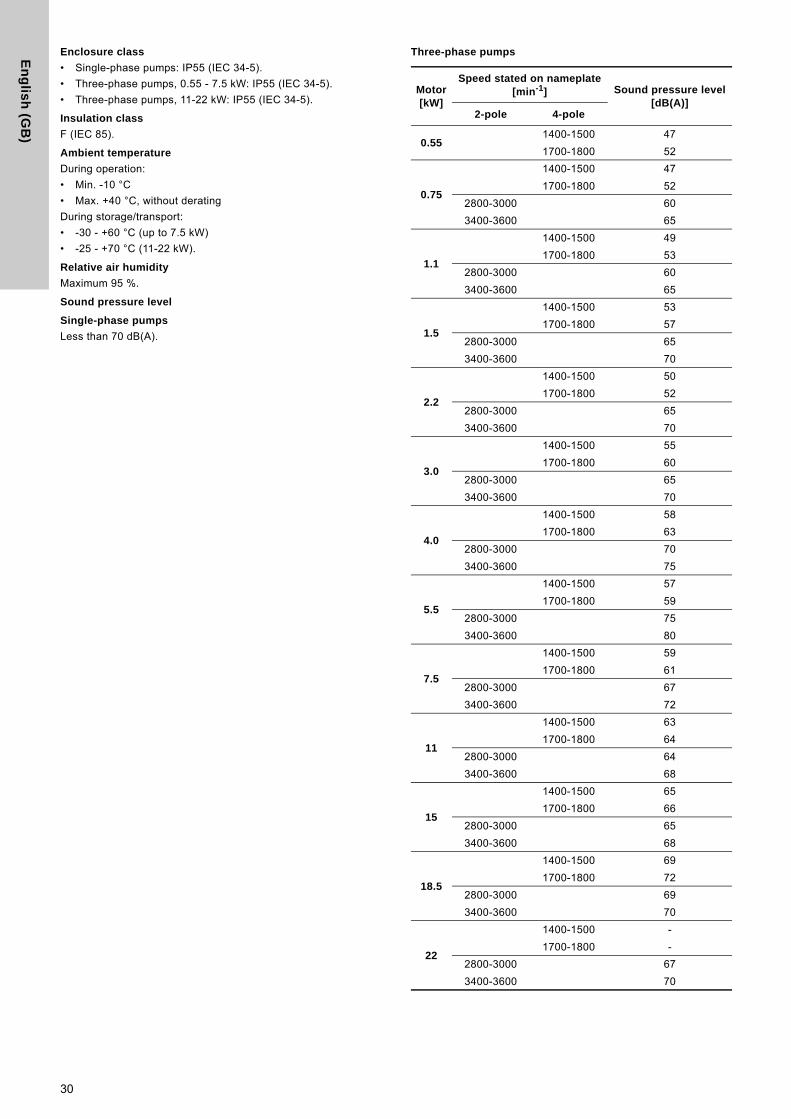
En
glis
h (G
B)
Enclosure class
• Single-phase pumps: IP55 (IEC 34-5).
• Three-phase pumps, 0.55 - 7.5 kW: IP55 (IEC 34-5).
• Three-phase pumps, 11-22 kW: IP55 (IEC 34-5).
Insulation class
F (IEC 85).
Ambient temperature
During operation:
• Min. -10 °C
• Max. +40 °C, without derating
During storage/transport:
• -30 - +60 °C (up to 7.5 kW)
• -25 - +70 °C (11-22 kW).
Relative air humidity
Maximum 95 %.
Sound pressure level
Single-phase pumps
Less than 70 dB(A).
Three-phase pumps
Motor[kW]
Speed stated on nameplate[min-1] Sound pressure level
[dB(A)]2-pole 4-pole
0.551400-1500 47
1700-1800 52
0.75
1400-1500 47
1700-1800 52
2800-3000 60
3400-3600 65
1.1
1400-1500 49
1700-1800 53
2800-3000 60
3400-3600 65
1.5
1400-1500 53
1700-1800 57
2800-3000 65
3400-3600 70
2.2
1400-1500 50
1700-1800 52
2800-3000 65
3400-3600 70
3.0
1400-1500 55
1700-1800 60
2800-3000 65
3400-3600 70
4.0
1400-1500 58
1700-1800 63
2800-3000 70
3400-3600 75
5.5
1400-1500 57
1700-1800 59
2800-3000 75
3400-3600 80
7.5
1400-1500 59
1700-1800 61
2800-3000 67
3400-3600 72
11
1400-1500 63
1700-1800 64
2800-3000 64
3400-3600 68
15
1400-1500 65
1700-1800 66
2800-3000 65
3400-3600 68
18.5
1400-1500 69
1700-1800 72
2800-3000 69
3400-3600 70
22
1400-1500 -
1700-1800 -
2800-3000 67
3400-3600 70
30

En
gli
sh
(G
B)
24. DisposalThis product or parts of it must be disposed of in an environmentally sound way:
1. Use the public or private waste collection service.
2. If this is not possible, contact the nearest Grundfos company or service workshop.
Subject to alterations.
31
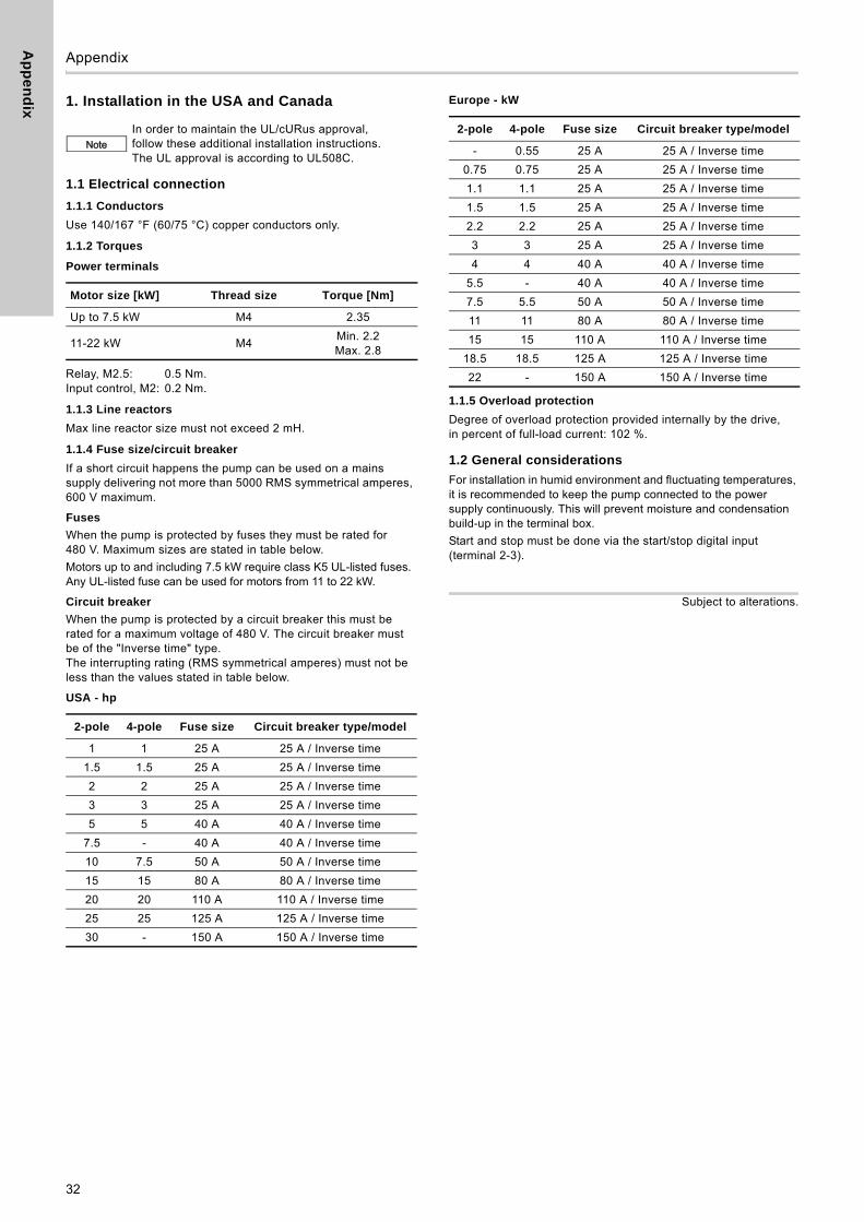
Ap
pe
nd
ix
32
Appendix 1
1. Installation in the USA and Canada
1.1 Electrical connection
1.1.1 Conductors
Use 140/167 °F (60/75 °C) copper conductors only.
1.1.2 Torques
Power terminals
Relay, M2.5: 0.5 Nm.Input control, M2: 0.2 Nm.
1.1.3 Line reactors
Max line reactor size must not exceed 2 mH.
1.1.4 Fuse size/circuit breaker
If a short circuit happens the pump can be used on a mains supply delivering not more than 5000 RMS symmetrical amperes, 600 V maximum.
Fuses
When the pump is protected by fuses they must be rated for 480 V. Maximum sizes are stated in table below.
Motors up to and including 7.5 kW require class K5 UL-listed fuses. Any UL-listed fuse can be used for motors from 11 to 22 kW.
Circuit breaker
When the pump is protected by a circuit breaker this must be rated for a maximum voltage of 480 V. The circuit breaker must be of the "Inverse time" type.The interrupting rating (RMS symmetrical amperes) must not be less than the values stated in table below.
USA - hp
Europe - kW
1.1.5 Overload protection
Degree of overload protection provided internally by the drive, in percent of full-load current: 102 %.
1.2 General considerations
For installation in humid environment and fluctuating temperatures, it is recommended to keep the pump connected to the power supply continuously. This will prevent moisture and condensation build-up in the terminal box.
Start and stop must be done via the start/stop digital input (terminal 2-3).
Subject to alterations.
NoteIn order to maintain the UL/cURus approval, follow these additional installation instructions. The UL approval is according to UL508C.
Motor size [kW] Thread size Torque [Nm]
Up to 7.5 kW M4 2.35
11-22 kW M4Min. 2.2Max. 2.8
2-pole 4-pole Fuse size Circuit breaker type/model
1 1 25 A 25 A / Inverse time
1.5 1.5 25 A 25 A / Inverse time
2 2 25 A 25 A / Inverse time
3 3 25 A 25 A / Inverse time
5 5 40 A 40 A / Inverse time
7.5 - 40 A 40 A / Inverse time
10 7.5 50 A 50 A / Inverse time
15 15 80 A 80 A / Inverse time
20 20 110 A 110 A / Inverse time
25 25 125 A 125 A / Inverse time
30 - 150 A 150 A / Inverse time
2-pole 4-pole Fuse size Circuit breaker type/model
- 0.55 25 A 25 A / Inverse time
0.75 0.75 25 A 25 A / Inverse time
1.1 1.1 25 A 25 A / Inverse time
1.5 1.5 25 A 25 A / Inverse time
2.2 2.2 25 A 25 A / Inverse time
3 3 25 A 25 A / Inverse time
4 4 40 A 40 A / Inverse time
5.5 - 40 A 40 A / Inverse time
7.5 5.5 50 A 50 A / Inverse time
11 11 80 A 80 A / Inverse time
15 15 110 A 110 A / Inverse time
18.5 18.5 125 A 125 A / Inverse time
22 - 150 A 150 A / Inverse time
Gru
nd
fos
co
mp
anie
s
ArgentinaBombas GRUNDFOS de Argentina S.A.Ruta Panamericana km. 37.500 Centro Industrial Garin1619 Garín Pcia. de B.A.Phone: +54-3327 414 444Telefax: +54-3327 45 3190
AustraliaGRUNDFOS Pumps Pty. Ltd. P.O. Box 2040 Regency Park South Australia 5942 Phone: +61-8-8461-4611 Telefax: +61-8-8340 0155
AustriaGRUNDFOS Pumpen Vertrieb Ges.m.b.H.Grundfosstraße 2 A-5082 Grödig/Salzburg Tel.: +43-6246-883-0 Telefax: +43-6246-883-30
BelgiumN.V. GRUNDFOS Bellux S.A. Boomsesteenweg 81-83 B-2630 Aartselaar Tél.: +32-3-870 7300 Télécopie: +32-3-870 7301
BelarusПредставительство ГРУНДФОС в Минске220125, Минскул. Шафарнянская, 11, оф. 56, БЦ «Порт»Тел.: +7 (375 17) 286 39 72/73Факс: +7 (375 17) 286 39 71E-mail: [email protected]
Bosna and HerzegovinaGRUNDFOS SarajevoZmaja od Bosne 7-7A,BH-71000 SarajevoPhone: +387 33 592 480Telefax: +387 33 590 465www.ba.grundfos.come-mail: [email protected]
BrazilBOMBAS GRUNDFOS DO BRASILAv. Humberto de Alencar Castelo Branco, 630CEP 09850 - 300São Bernardo do Campo - SPPhone: +55-11 4393 5533Telefax: +55-11 4343 5015
BulgariaGrundfos Bulgaria EOODSlatina DistrictIztochna Tangenta street no. 100BG - 1592 SofiaTel. +359 2 49 22 200Fax. +359 2 49 22 201email: [email protected]
CanadaGRUNDFOS Canada Inc. 2941 Brighton Road Oakville, Ontario L6H 6C9 Phone: +1-905 829 9533 Telefax: +1-905 829 9512
ChinaGRUNDFOS Pumps (Shanghai) Co. Ltd.10F The Hub, No. 33 Suhong RoadMinhang DistrictShanghai 201106PRCPhone: +86 21 612 252 22Telefax: +86 21 612 253 33
CroatiaGRUNDFOS CROATIA d.o.o.Buzinski prilaz 38, BuzinHR-10010 ZagrebPhone: +385 1 6595 400 Telefax: +385 1 6595 499www.hr.grundfos.com
Czech RepublicGRUNDFOS s.r.o.Čajkovského 21779 00 OlomoucPhone: +420-585-716 111Telefax: +420-585-716 299
DenmarkGRUNDFOS DK A/S Martin Bachs Vej 3 DK-8850 Bjerringbro Tlf.: +45-87 50 50 50 Telefax: +45-87 50 51 51 E-mail: [email protected]/DK
EstoniaGRUNDFOS Pumps Eesti OÜPeterburi tee 92G11415 TallinnTel: + 372 606 1690Fax: + 372 606 1691
FinlandOY GRUNDFOS Pumput AB Trukkikuja 1 FI-01360 Vantaa Phone: +358-(0) 207 889 500Telefax: +358-(0) 207 889 550
FrancePompes GRUNDFOS Distribution S.A. Parc d’Activités de Chesnes 57, rue de Malacombe F-38290 St. Quentin Fallavier (Lyon) Tél.: +33-4 74 82 15 15 Télécopie: +33-4 74 94 10 51
GermanyGRUNDFOS GMBHSchlüterstr. 3340699 ErkrathTel.: +49-(0) 211 929 69-0 Telefax: +49-(0) 211 929 69-3799e-mail: [email protected] in Deutschland:e-mail: [email protected]
GreeceGRUNDFOS Hellas A.E.B.E. 20th km. Athinon-Markopoulou Av. P.O. Box 71 GR-19002 Peania Phone: +0030-210-66 83 400 Telefax: +0030-210-66 46 273
Hong KongGRUNDFOS Pumps (Hong Kong) Ltd. Unit 1, Ground floor Siu Wai Industrial Centre 29-33 Wing Hong Street & 68 King Lam Street, Cheung Sha Wan Kowloon Phone: +852-27861706 / 27861741 Telefax: +852-27858664
HungaryGRUNDFOS Hungária Kft.Park u. 8H-2045 Törökbálint, Phone: +36-23 511 110Telefax: +36-23 511 111
IndiaGRUNDFOS Pumps India Private Limited118 Old Mahabalipuram RoadThoraipakkamChennai 600 096Phone: +91-44 2496 6800
IndonesiaPT. GRUNDFOS POMPAGraha Intirub Lt. 2 & 3Jln. Cililitan Besar No.454. Makasar, Jakarta TimurID-Jakarta 13650Phone: +62 21-469-51900Telefax: +62 21-460 6910 / 460 6901
IrelandGRUNDFOS (Ireland) Ltd. Unit A, Merrywell Business ParkBallymount Road LowerDublin 12 Phone: +353-1-4089 800 Telefax: +353-1-4089 830
ItalyGRUNDFOS Pompe Italia S.r.l. Via Gran Sasso 4I-20060 Truccazzano (Milano)Tel.: +39-02-95838112 Telefax: +39-02-95309290 / 95838461
JapanGRUNDFOS Pumps K.K.Gotanda Metalion Bldg., 5F, 5-21-15, Higashi-gotandaShiagawa-ku, Tokyo141-0022 JapanPhone: +81 35 448 1391Telefax: +81 35 448 9619
KoreaGRUNDFOS Pumps Korea Ltd.6th Floor, Aju Building 679-5Yeoksam-dong, Kangnam-ku, 135-916Seoul, KoreaPhone: +82-2-5317 600Telefax: +82-2-5633 725
LatviaSIA GRUNDFOS Pumps Latvia Deglava biznesa centrsAugusta Deglava ielā 60, LV-1035, Rīga,Tālr.: + 371 714 9640, 7 149 641Fakss: + 371 914 9646
LithuaniaGRUNDFOS Pumps UABSmolensko g. 6LT-03201 VilniusTel: + 370 52 395 430Fax: + 370 52 395 431
MalaysiaGRUNDFOS Pumps Sdn. Bhd.7 Jalan Peguam U1/25Glenmarie Industrial Park40150 Shah AlamSelangor Phone: +60-3-5569 2922Telefax: +60-3-5569 2866
MexicoBombas GRUNDFOS de México S.A. de C.V. Boulevard TLC No. 15Parque Industrial Stiva AeropuertoApodaca, N.L. 66600Phone: +52-81-8144 4000 Telefax: +52-81-8144 4010
NetherlandsGRUNDFOS NetherlandsVeluwezoom 351326 AE AlmerePostbus 220151302 CA ALMERE Tel.: +31-88-478 6336 Telefax: +31-88-478 6332E-mail: [email protected]
New ZealandGRUNDFOS Pumps NZ Ltd.17 Beatrice Tinsley CrescentNorth Harbour Industrial EstateAlbany, AucklandPhone: +64-9-415 3240Telefax: +64-9-415 3250
NorwayGRUNDFOS Pumper A/S Strømsveien 344 Postboks 235, Leirdal N-1011 Oslo Tlf.: +47-22 90 47 00 Telefax: +47-22 32 21 50
PolandGRUNDFOS Pompy Sp. z o.o.ul. Klonowa 23Baranowo k. PoznaniaPL-62-081 PrzeźmierowoTel: (+48-61) 650 13 00Fax: (+48-61) 650 13 50
PortugalBombas GRUNDFOS Portugal, S.A. Rua Calvet de Magalhães, 241Apartado 1079P-2770-153 Paço de ArcosTel.: +351-21-440 76 00Telefax: +351-21-440 76 90
RomaniaGRUNDFOS Pompe România SRLBd. Biruintei, nr 103 Pantelimon county IlfovPhone: +40 21 200 4100Telefax: +40 21 200 4101E-mail: [email protected]
RussiaООО Грундфос Россия109544, г. Москва, ул. Школьная, 39-41, стр. 1Тел. (+7) 495 564-88-00 (495) 737-30-00Факс (+7) 495 564 88 11E-mail [email protected]
Serbia Grundfos Srbija d.o.o.Omladinskih brigada 90b11070 Novi Beograd Phone: +381 11 2258 740Telefax: +381 11 2281 769www.rs.grundfos.com
SingaporeGRUNDFOS (Singapore) Pte. Ltd.25 Jalan Tukang Singapore 619264 Phone: +65-6681 9688 Telefax: +65-6681 9689
SlovakiaGRUNDFOS s.r.o.Prievozská 4D 821 09 BRATISLAVA Phona: +421 2 5020 1426sk.grundfos.com
SloveniaGRUNDFOS d.o.o.Šlandrova 8b, SI-1231 Ljubljana-ČrnučePhone: +386 31 718 808Telefax: +386 (0)1 5680 619E-mail: [email protected]
South AfricaGRUNDFOS (PTY) LTDCorner Mountjoy and George Allen RoadsWilbart Ext. 2Bedfordview 2008Phone: (+27) 11 579 4800Fax: (+27) 11 455 6066E-mail: [email protected]
SpainBombas GRUNDFOS España S.A. Camino de la Fuentecilla, s/n E-28110 Algete (Madrid) Tel.: +34-91-848 8800 Telefax: +34-91-628 0465
SwedenGRUNDFOS AB Box 333 (Lunnagårdsgatan 6) 431 24 Mölndal Tel.: +46 31 332 23 000Telefax: +46 31 331 94 60
SwitzerlandGRUNDFOS Pumpen AG Bruggacherstrasse 10 CH-8117 Fällanden/ZH Tel.: +41-44-806 8111 Telefax: +41-44-806 8115
TaiwanGRUNDFOS Pumps (Taiwan) Ltd. 7 Floor, 219 Min-Chuan Road Taichung, Taiwan, R.O.C. Phone: +886-4-2305 0868Telefax: +886-4-2305 0878
ThailandGRUNDFOS (Thailand) Ltd. 92 Chaloem Phrakiat Rama 9 Road,Dokmai, Pravej, Bangkok 10250Phone: +66-2-725 8999Telefax: +66-2-725 8998
TurkeyGRUNDFOS POMPA San. ve Tic. Ltd. Sti.Gebze Organize Sanayi Bölgesi Ihsan dede Caddesi,2. yol 200. Sokak No. 20441490 Gebze/ KocaeliPhone: +90 - 262-679 7979Telefax: +90 - 262-679 7905E-mail: [email protected]
UkraineБізнес Центр ЄвропаСтоличне шосе, 103м. Київ, 03131, Україна Телефон: (+38 044) 237 04 00 Факс.: (+38 044) 237 04 01E-mail: [email protected]
United Arab EmiratesGRUNDFOS Gulf DistributionP.O. Box 16768Jebel Ali Free ZoneDubaiPhone: +971 4 8815 166Telefax: +971 4 8815 136
United KingdomGRUNDFOS Pumps Ltd. Grovebury Road Leighton Buzzard/Beds. LU7 4TL Phone: +44-1525-850000 Telefax: +44-1525-850011
U.S.A.GRUNDFOS Pumps Corporation 17100 West 118th TerraceOlathe, Kansas 66061Phone: +1-913-227-3400 Telefax: +1-913-227-3500
UzbekistanGrundfos Tashkent, Uzbekistan The Representative Office of Grundfos Kazakhstan in Uzbekistan38a, Oybek street, TashkentТелефон: (+998) 71 150 3290 / 71 150 3291Факс: (+998) 71 150 3292
Addresses Revised 29.09.2015

96782378 1215
ECM: 1171867 The
nam
e G
rund
fos,
the
Gru
ndfo
s lo
go, a
nd b
e t
hin
k i
nn
ov
ate
are
regi
ster
ed tr
adem
arks
ow
ned
by G
rund
fos
Hol
ding
A/S
or G
rund
fos
A/S,
Den
mar
k. A
ll rig
hts
rese
rved
wor
ldw
ide.
© C
opyr
ight
Gru
ndfo
s H
oldi
ng A
/S
www.grundfos.com