tps92310 triac dimmable ac-dc led driver reference · pdf filetps92310 . triac dimmable ac-dc...
TRANSCRIPT
TPS92310 Triac Dimmable AC-DC LED Driver Reference Design
Literature Number: SLVU830 January, 2013

SLVU830
2 Triac Dimmable Off-Line Primary Side-Sensing Controller with PFC
Triac Dimmable Off-Line Primary Side-Sensing Controller with PFC 1 Introduction
This TPS92310 reference design presents the TPS92310 AC-DC controller in a configuration that is compatible with triac dimmers. The TPS92310 is designed to drive high-brightness light emitting diodes (LEDs) and features-programmable ON time, programmable delay, and zero-current detection. Additional features include cycle-by-cycle switch current limit, VCC under-voltage lockout, and output over-voltage protection.
2 Description This reference design provides a high-brightness LED driver based on the TPS92310 configured as a power factor corrected flyback regulator that is triac dimmable. It is designed to operate with an input voltage in the range of 90 VAC to 135 VAC with a 120-VAC nominal input voltage. This design is set up for a default output current of 340 mA with an output voltage range of 21 V to 27 V or approximately 6 to 8 LEDs depending on the forward voltage of each.
2.1 Typical Applications
This converter design describes an application of the TPS92310 as an LED driver with the specifications listed below. For applications with a different input voltage range or different output voltage range, refer to the TPS92310 datasheet.
2.2 Features
2.2.1 Connector Description
This section describes the connectors and test points on the reference design board and how to properly connect, setup, and use the TPS92310.
2.2.1.1 CN1
This connector is for the AC input to the board. Use the screw down terminals to connect Line and Neutral to the circuit. Pin 1 is marked LINE while pin 2 is marked NEUTRAL. Since no earth ground is used, these two are interchangeable.
2.2.1.2 LED+, LED–, CN2
Connect the LED string between these test points with the anode of one end connected to LED+ and the cathode of the other end connected to LED–. Alternatively, the screw down connector CN2 may be used. Pin 1 of CN2 is LED+ and pin 2 is LED–.

SLVU830
Triac Dimmable Off-Line Primary Side-Sensing Controller with PFC 3
3 Electrical Performance Specifications
Table 1. TPS92310 Triac Dimmable Electrical Performance Specifications
Parameter Test Conditions MIN TYP MAX Units Input Characteristics Voltage range 90 120 135 VAC Maximum input current At IOUT = 340 mA 85 mA Output Characteristics Output voltage, VOUT At IOUT = 340 mA 21 27 V Output load current, IOUT No Triac dimmer 323 340 357 mA Output current regulation At 120VAC input voltage ±5 % Output current ripple At IOUT = 340 mA 125 mApp Over-voltage protection level Output rising 28 30 32 V Systems Characteristics Switching frequency 48 kHz
Efficiency Input voltage = 120VAC, Load = 7 LEDs at 24.5 V 84 %
Power Factor Input voltage = 120VAC, Load = 7 LEDs at 24.5 V 0.943
Triac Dim range Dependent upon dimmer used 6:1 15:1

SLVU830
4 Triac Dimmable Off-Line Primary Side-Sensing Controller with PFC
4 Schematic
Figure 1. TPS92310 Dimmable Schematic

SLVU830
Triac Dimmable Off-Line Primary Side-Sensing Controller with PFC 5
5 Performance Data and Typical Characteristic Curves Figure 2 through Figure 10 present typical performance curves for the TPS92310 dimmable design.
5.1 Efficiency
Figure 2. Efficiency
5.2 Line Regulation
Figure 3. Line Regulation

SLVU830
6 Triac Dimmable Off-Line Primary Side-Sensing Controller with PFC
5.3 Power Factor
Figure 4. Power Factor
5.4 Output Current over Ambient Temperature
Figure 5. Output Current versus Temperature

SLVU830
Triac Dimmable Off-Line Primary Side-Sensing Controller with PFC 7
5.5 Triac Dimmer Response
Figure 6. Triac Maximum Level Waveform
Figure 7. 90 Degree Conduction Angle Waveform

SLVU830
8 Triac Dimmable Off-Line Primary Side-Sensing Controller with PFC
Figure 8. Triac Minimum Level Waveform
Att 10 dB*
*
*
*1 AVCLRWR
A SGL
6DB
RBW 9 kHzVBW 10 HzSWT 340 s
TDF
Ref 100 dBµV
Center 2.121320344 MHz Span 29.85 MHz
1 MHz 10 MHz
0
10
20
30
40
50
60
70
80
90
100
1
Marker 1 [T1 ] 25.91 dBµV 243.193957726 kHz
FCC15QPK
FCC15AVG
Date: 27.AUG.2012 12:21:09
Figure 9. 120VAC Line-Conducted Average EMI Scan
SLVU830
Triac Dimmable Off-Line Primary Side-Sensing Controller with PFC 9
Att 10 dB*
*
*
*1 AVCLRWR
A SGL
6DB
RBW 9 kHzVBW 10 HzSWT 340 s
TDF
Ref 100 dBµV
Center 2.121320344 MHz Span 29.85 MHz
1 MHz 10 MHz
0
10
20
30
40
50
60
70
80
90
100
1
Marker 1 [T1 ] 27.86 dBµV 243.193957726 kHz
FCC15QPK
FCC15AVG
Date: 27.AUG.2012 12:28:35
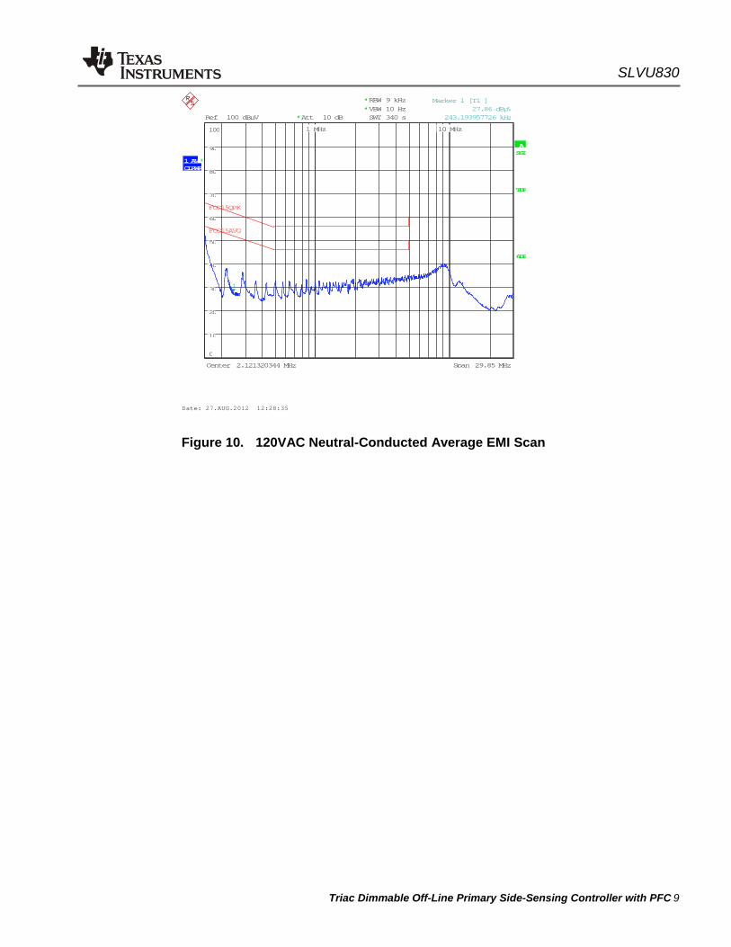
Figure 10. 120VAC Neutral-Conducted Average EMI Scan

SLVU830
10 Triac Dimmable Off-Line Primary Side-Sensing Controller with PFC
6 TPS92310 Dimmable Reference Design Printed-Circuit Board Layout Figure 11 and Figure 12 show the design of the TPS92310 dimmable printed-circuit board.
Figure 11. Top Layer and Top Overlay (Top view)
Figure 12. Bottom Layer and Bottom Overlay (Bottom view)
SLVU830
Triac Dimmable Off-Line Primary Side-Sensing Controller with PFC 11
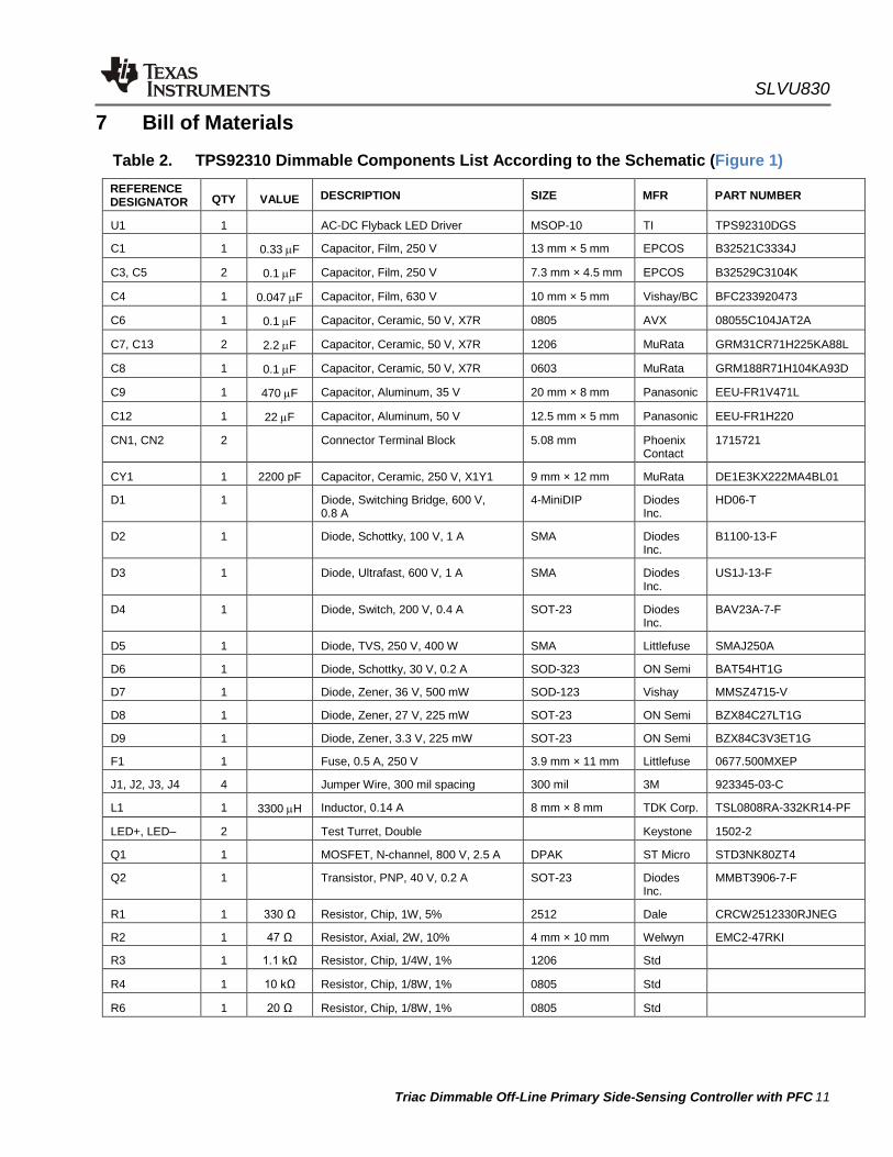
7 Bill of Materials
Table 2. TPS92310 Dimmable Components List According to the Schematic (Figure 1) REFERENCE DESIGNATOR QTY VALUE DESCRIPTION SIZE MFR PART NUMBER
U1 1 AC-DC Flyback LED Driver MSOP-10 TI TPS92310DGS
C1 1 0.33 µF Capacitor, Film, 250 V 13 mm × 5 mm EPCOS B32521C3334J
C3, C5 2 0.1 µF Capacitor, Film, 250 V 7.3 mm × 4.5 mm EPCOS B32529C3104K
C4 1 0.047 µF Capacitor, Film, 630 V 10 mm × 5 mm Vishay/BC BFC233920473
C6 1 0.1 µF Capacitor, Ceramic, 50 V, X7R 0805 AVX 08055C104JAT2A
C7, C13 2 2.2 µF Capacitor, Ceramic, 50 V, X7R 1206 MuRata GRM31CR71H225KA88L
C8 1 0.1 µF Capacitor, Ceramic, 50 V, X7R 0603 MuRata GRM188R71H104KA93D
C9 1 470 µF Capacitor, Aluminum, 35 V 20 mm × 8 mm Panasonic EEU-FR1V471L
C12 1 22 µF Capacitor, Aluminum, 50 V 12.5 mm × 5 mm Panasonic EEU-FR1H220
CN1, CN2 2 Connector Terminal Block 5.08 mm Phoenix Contact
1715721
CY1 1 2200 pF Capacitor, Ceramic, 250 V, X1Y1 9 mm × 12 mm MuRata DE1E3KX222MA4BL01
D1 1 Diode, Switching Bridge, 600 V, 0.8 A
4-MiniDIP Diodes Inc.
HD06-T
D2 1 Diode, Schottky, 100 V, 1 A SMA Diodes Inc.
B1100-13-F
D3 1 Diode, Ultrafast, 600 V, 1 A SMA Diodes Inc.
US1J-13-F
D4 1 Diode, Switch, 200 V, 0.4 A SOT-23 Diodes Inc.
BAV23A-7-F
D5 1 Diode, TVS, 250 V, 400 W SMA Littlefuse SMAJ250A
D6 1 Diode, Schottky, 30 V, 0.2 A SOD-323 ON Semi BAT54HT1G
D7 1 Diode, Zener, 36 V, 500 mW SOD-123 Vishay MMSZ4715-V
D8 1 Diode, Zener, 27 V, 225 mW SOT-23 ON Semi BZX84C27LT1G
D9 1 Diode, Zener, 3.3 V, 225 mW SOT-23 ON Semi BZX84C3V3ET1G
F1 1 Fuse, 0.5 A, 250 V 3.9 mm × 11 mm Littlefuse 0677.500MXEP
J1, J2, J3, J4 4 Jumper Wire, 300 mil spacing 300 mil 3M 923345-03-C
L1 1 3300 µH Inductor, 0.14 A 8 mm × 8 mm TDK Corp. TSL0808RA-332KR14-PF
LED+, LED– 2 Test Turret, Double Keystone 1502-2
Q1 1 MOSFET, N-channel, 800 V, 2.5 A DPAK ST Micro STD3NK80ZT4
Q2 1 Transistor, PNP, 40 V, 0.2 A SOT-23 Diodes Inc.
MMBT3906-7-F
R1 1 330 Ω Resistor, Chip, 1W, 5% 2512 Dale CRCW2512330RJNEG
R2 1 47 Ω Resistor, Axial, 2W, 10% 4 mm × 10 mm Welwyn EMC2-47RKI
R3 1 1.1 kΩ Resistor, Chip, 1/4W, 1% 1206 Std
R4 1 10 kΩ Resistor, Chip, 1/8W, 1% 0805 Std
R6 1 20 Ω Resistor, Chip, 1/8W, 1% 0805 Std

SLVU830
12 Triac Dimmable Off-Line Primary Side-Sensing Controller with PFC
R8 1 1.43 Ω Resistor, Chip, 1/4W, 1% 1206 Yageo RC1206FR-071R43L
R10 1 6.34 kΩ Resistor, Chip, 1/10W, 1% 0603 Std
R11 1 200 kΩ Resistor, Chip, 1/4W, 1% 1206 Std
R15 1 100 kΩ Resistor, Chip, 1/4W, 1% 1206 Std
R17 1 64.9 kΩ Resistor, Chip, 1/10W, 1% 0603 Std
R19 1 20 kΩ Resistor, Chip, 1/8W, 1% 0805 Std
R20 1 200 Ω Resistor, Chip, 1/8W, 1% 0805 Std
R21 1 100 Ω Resistor, Chip, 1/10W, 1% 0603 Std
R22 1 2 MΩ Resistor, Chip, 1/4W, 1% 1206 Std
R24 1 39.2 kΩ Resistor, Chip, 1/10W, 1% 0603 Std
T1 1 Transformer EE-16 Wurth 750341086
TP1, TP2 0 DNP Test Point, SMT Keystone 5015
VR1 1 Varistor, 300 VAC, 385 VDC, 30J 7 mm Radial EPCOS S07K300E2

SLVU830
Triac Dimmable Off-Line Primary Side-Sensing Controller with PFC 13
EVALUATION BOARD/KIT/MODULE (REF DESIGN) WARNINGS, RESTRICTIONS AND DISCLAIMER
For Feasibility Evaluation Only, in Laboratory/Development Environments. The REF DESIGN is not a complete product. It is intended solely for use for preliminary feasibility evaluation in laboratory / development environments by technically qualified electronics experts who are familiar with the dangers and application risks associated with handling electrical / mechanical components, systems and subsystems. It should not be used as all or part of a production unit.
Your Sole Responsibility and Risk. You acknowledge, represent and agree that:
1. You have unique knowledge concerning Federal, State and local regulatory requirements (including but not limited to Food and Drug Administration regulations, if applicable) which relate to your products and which relate to your use (and/or that of your employees, affiliates, contractors or designees) of the REF DESIGN for evaluation, testing and other purposes.
2. You have full and exclusive responsibility to assure the safety and compliance of your products with all such laws and other applicable regulatory requirements, and also to assure the safety of any activities to be conducted by you and/or your employees, affiliates, contractors or designees, using the REF DESIGN. Further, you are responsible to assure that any interfaces (electronic and/or mechanical) between the REF DESIGN and any human body are designed with suitable isolation and means to safely limit accessible leakage currents to minimize the risk of electrical shock hazard.
3. Since the REF DESIGN is not a completed product, it may not meet all applicable regulatory and safety compliance standards (such as UL, CSA, VDE, CE, RoHS and WEEE) which may normally be associated with similar items. You assume full responsibility to determine and/or assure compliance with any such standards and related certifications as may be applicable. You will employ reasonable safeguards to ensure that your use of the REF DESIGN will not result in any property damage, injury or death, even if the REF DESIGN should fail to perform as described or expected.
Certain Instructions. Exceeding the specified REF DESIGN ratings (including but not limited to input and output voltage, current, power, and environmental ranges) may cause property damage, personal injury or death. If there are questions concerning these ratings please contact a TI field representative prior to connecting interface electronics including input power and intended loads. Any loads applied outside of the specified output range may result in unintended and/or inaccurate operation and/or possible permanent damage to the REF DESIGN and/or interface electronics. Please consult the REF DESIGN User’s Guide prior to connecting any load to the REF DESIGN output. If there is uncertainty as to the load specification, please contact a TI field representative. During normal operation, some circuit components may have case temperatures greater than 60°C as long as the input and output ranges are maintained at nominal ambient operating temperature. These components include but are not limited to linear regulators, switching transistors, pass transistors, and current sense resistors which can be indentified using the REF DESIGN schematic located in the REF DESIGN User’s Guide. When placing measurement probes near these devices during normal operation, please be aware that these devices may be very warm to the touch. Agreement to Defend, Indemnify and Hold Harmless. You agree to defend, indemnify and hold TI, its licensors and their representatives harmless from and against any and all claims, damages, losses, expenses, costs and liabilities (collectively, “Claims”) arising out of or in connection with any use of the REF DESIGN that is not in accordance with the terms of this agreement. This obligation shall apply whether Claims arise under the law of tort or contract or any other legal theory, and even if the REF DESIGN fails to perform as described or expected.
Safety-Critical or Life-Critical Applications. If you intend to evaluate TI components for possible use in safety-critical applications (such as life support) where a failure of the TI product would reasonably be expected to cause severe personal injury or death, such as devices which are classified as FDA Class III or similar classification, then you must specifically notify TI of such intent and enter into a separate Assurance and Indemnity Agreement.
SLVU830
14 Triac Dimmable Off-Line Primary Side-Sensing Controller with PFC
IMPORTANT NOTICE Texas Instruments Incorporated and its subsidiaries (TI) reserve the right to make corrections, modifications, enhancements, improvements, and other changes to its products and services at any time and to discontinue any product or service without notice. Customers should obtain the latest relevant information before placing orders and should verify that such information is current and complete. All products are sold subject to TI’s terms and conditions of sale supplied at the time of order acknowledgment. TI warrants performance of its hardware products to the specifications applicable at the time of sale in accordance with TI’s standard warranty. Testing and other quality control techniques are used to the extent TI deems necessary to support this warranty. Except where mandated by government requirements, testing of all parameters of each product is not necessarily performed. TI assumes no liability for applications assistance or customer product design. Customers are responsible for their products and applications using TI components. To minimize the risks associated with customer products and applications, customers should provide adequate design and operating safeguards. TI does not warrant or represent that any license, either express or implied, is granted under any TI patent right, copyright, mask work right, or other TI intellectual property right relating to any combination, machine, or process in which TI products or services are used. Information published by TI regarding third-party products or services does not constitute a license from TI to use such products or services or a warranty or endorsement thereof. Use of such information may require a license from a third party under the patents or other intellectual property of the third party, or a license from TI under the patents or other intellectual property of TI. Reproduction of TI information in TI data books or data sheets is permissible only if reproduction is without alteration and is accompanied by all associated warranties, conditions, limitations, and notices. Reproduction of this information with alteration is an unfair and deceptive business practice. TI is not responsible or liable for such altered documentation. Information of third parties may be subject to additional restrictions. Resale of TI products or services with statements different from or beyond the parameters stated by TI for that product or service voids all express and any implied warranties for the associated TI product or service and is an unfair and deceptive business practice. TI is not responsible or liable for any such statements. TI products are not authorized for use in safety-critical applications (such as life support) where a failure of the TI product would reasonably be expected to cause severe personal injury or death, unless officers of the parties have executed an agreement specifically governing such use. Buyers represent that they have all necessary expertise in the safety and regulatory ramifications of their applications, and acknowledge and agree that they are solely responsible for all legal, regulatory and safety-related requirements concerning their products and any use of TI products in such safety-critical applications, notwithstanding any applications-related information or support that may be provided by TI. Further, Buyers must fully indemnify TI and its representatives against any damages arising out of the use of TI products in such safety-critical applications. TI products are neither designed nor intended for use in military/aerospace applications or environments unless the TI products are specifically designated by TI as military-grade or "enhanced plastic." Only products designated by TI as military-grade meet military specifications. Buyers acknowledge and agree that any such use of TI products which TI has not designated as military-grade is solely at the Buyer's risk, and that they are solely responsible for compliance with all legal and regulatory requirements in connection with such use. TI products are neither designed nor intended for use in automotive applications or environments unless the specific TI products are designated by TI as compliant with ISO/TS 16949 requirements. Buyers acknowledge and agree that, if they use any non-designated products in automotive applications, TI will not be responsible for any failure to meet such requirements. Following are URLs where you can obtain information on other Texas Instruments products and application solutions: Products Amplifiers Data Converters DSP Clocks and Timers Interface Logic Power Mgmt Microcontrollers RFID RF/IF and ZigBee® Solutions
amplifier.ti.com dataconverter.ti.com dsp.ti.com www.ti.com/clocks interface.ti.com logic.ti.com power.ti.com microcontroller.ti.com www.ti-rfid.com www.ti.com/lprf
Applications Audio Automotive Broadband Digital Control Medical Military Optical Networking Security Telephony Video & Imaging Wireless
www.ti.com/audio www.ti.com/automotive www.ti.com/broadband www.ti.com/digitalcontrol www.ti.com/medical www.ti.com/military www.ti.com/opticalnetwork www.ti.com/security www.ti.com/telephony www.ti.com/video www.ti.com/wireless
Mailing Address: Texas Instruments, Post Office Box 655303, Dallas, Texas 75265 Copyright © 2013, Texas Instruments Incorporated

IMPORTANT NOTICE
Texas Instruments Incorporated and its subsidiaries (TI) reserve the right to make corrections, enhancements, improvements and otherchanges to its semiconductor products and services per JESD46, latest issue, and to discontinue any product or service per JESD48, latestissue. Buyers should obtain the latest relevant information before placing orders and should verify that such information is current andcomplete. All semiconductor products (also referred to herein as “components”) are sold subject to TI’s terms and conditions of salesupplied at the time of order acknowledgment.
TI warrants performance of its components to the specifications applicable at the time of sale, in accordance with the warranty in TI’s termsand conditions of sale of semiconductor products. Testing and other quality control techniques are used to the extent TI deems necessaryto support this warranty. Except where mandated by applicable law, testing of all parameters of each component is not necessarilyperformed.
TI assumes no liability for applications assistance or the design of Buyers’ products. Buyers are responsible for their products andapplications using TI components. To minimize the risks associated with Buyers’ products and applications, Buyers should provideadequate design and operating safeguards.
TI does not warrant or represent that any license, either express or implied, is granted under any patent right, copyright, mask work right, orother intellectual property right relating to any combination, machine, or process in which TI components or services are used. Informationpublished by TI regarding third-party products or services does not constitute a license to use such products or services or a warranty orendorsement thereof. Use of such information may require a license from a third party under the patents or other intellectual property of thethird party, or a license from TI under the patents or other intellectual property of TI.
Reproduction of significant portions of TI information in TI data books or data sheets is permissible only if reproduction is without alterationand is accompanied by all associated warranties, conditions, limitations, and notices. TI is not responsible or liable for such altereddocumentation. Information of third parties may be subject to additional restrictions.
Resale of TI components or services with statements different from or beyond the parameters stated by TI for that component or servicevoids all express and any implied warranties for the associated TI component or service and is an unfair and deceptive business practice.TI is not responsible or liable for any such statements.
Buyer acknowledges and agrees that it is solely responsible for compliance with all legal, regulatory and safety-related requirementsconcerning its products, and any use of TI components in its applications, notwithstanding any applications-related information or supportthat may be provided by TI. Buyer represents and agrees that it has all the necessary expertise to create and implement safeguards whichanticipate dangerous consequences of failures, monitor failures and their consequences, lessen the likelihood of failures that might causeharm and take appropriate remedial actions. Buyer will fully indemnify TI and its representatives against any damages arising out of the useof any TI components in safety-critical applications.
In some cases, TI components may be promoted specifically to facilitate safety-related applications. With such components, TI’s goal is tohelp enable customers to design and create their own end-product solutions that meet applicable functional safety standards andrequirements. Nonetheless, such components are subject to these terms.
No TI components are authorized for use in FDA Class III (or similar life-critical medical equipment) unless authorized officers of the partieshave executed a special agreement specifically governing such use.
Only those TI components which TI has specifically designated as military grade or “enhanced plastic” are designed and intended for use inmilitary/aerospace applications or environments. Buyer acknowledges and agrees that any military or aerospace use of TI componentswhich have not been so designated is solely at the Buyer's risk, and that Buyer is solely responsible for compliance with all legal andregulatory requirements in connection with such use.
TI has specifically designated certain components as meeting ISO/TS16949 requirements, mainly for automotive use. In any case of use ofnon-designated products, TI will not be responsible for any failure to meet ISO/TS16949.
Products Applications
Audio www.ti.com/audio Automotive and Transportation www.ti.com/automotive
Amplifiers amplifier.ti.com Communications and Telecom www.ti.com/communications
Data Converters dataconverter.ti.com Computers and Peripherals www.ti.com/computers
DLP® Products www.dlp.com Consumer Electronics www.ti.com/consumer-apps
DSP dsp.ti.com Energy and Lighting www.ti.com/energy
Clocks and Timers www.ti.com/clocks Industrial www.ti.com/industrial
Interface interface.ti.com Medical www.ti.com/medical
Logic logic.ti.com Security www.ti.com/security
Power Mgmt power.ti.com Space, Avionics and Defense www.ti.com/space-avionics-defense
Microcontrollers microcontroller.ti.com Video and Imaging www.ti.com/video
RFID www.ti-rfid.com
OMAP Applications Processors www.ti.com/omap TI E2E Community e2e.ti.com
Wireless Connectivity www.ti.com/wirelessconnectivity
Mailing Address: Texas Instruments, Post Office Box 655303, Dallas, Texas 75265Copyright © 2013, Texas Instruments Incorporated