tr 126 980 - v13.0.0 - universal mobile telecommunications system (umts); lte ...€¦ · ·...
TRANSCRIPT
ETSI TR 1
Universal Mobile Tel
Multimedia telephony Media handling as
conferencing for Multim(3GPP TR 26.9
TECHNICAL REPORT
126 980 V13.0.0 (2016
elecommunications System (LTE;
y over IP Multimedia Subsyste aspects of multi-stream multipimedia Telephony Service for .980 version 13.0.0 Release 13
16-01)
(UMTS);
stem (IMS); ltiparty or IMS (MTSI) 13)

ETSI
ETSI TR 126 980 V13.0.0 (2016-01)13GPP TR 26.980 version 13.0.0 Release 13
Reference DTR/TSGS-0426980vd00
Keywords LTE,UMTS
ETSI
650 Route des Lucioles F-06921 Sophia Antipolis Cedex - FRANCE
Tel.: +33 4 92 94 42 00 Fax: +33 4 93 65 47 16
Siret N° 348 623 562 00017 - NAF 742 C
Association à but non lucratif enregistrée à la Sous-Préfecture de Grasse (06) N° 7803/88
Important notice
The present document can be downloaded from: http://www.etsi.org/standards-search
The present document may be made available in electronic versions and/or in print. The content of any electronic and/or print versions of the present document shall not be modified without the prior written authorization of ETSI. In case of any
existing or perceived difference in contents between such versions and/or in print, the only prevailing document is the print of the Portable Document Format (PDF) version kept on a specific network drive within ETSI Secretariat.
Users of the present document should be aware that the document may be subject to revision or change of status. Information on the current status of this and other ETSI documents is available at
http://portal.etsi.org/tb/status/status.asp
If you find errors in the present document, please send your comment to one of the following services: https://portal.etsi.org/People/CommiteeSupportStaff.aspx
Copyright Notification
No part may be reproduced or utilized in any form or by any means, electronic or mechanical, including photocopying and microfilm except as authorized by written permission of ETSI.
The content of the PDF version shall not be modified without the written authorization of ETSI. The copyright and the foregoing restriction extend to reproduction in all media.
© European Telecommunications Standards Institute 2016.
All rights reserved.
DECTTM, PLUGTESTSTM, UMTSTM and the ETSI logo are Trade Marks of ETSI registered for the benefit of its Members. 3GPPTM and LTE™ are Trade Marks of ETSI registered for the benefit of its Members and
of the 3GPP Organizational Partners. GSM® and the GSM logo are Trade Marks registered and owned by the GSM Association.

ETSI
ETSI TR 126 980 V13.0.0 (2016-01)23GPP TR 26.980 version 13.0.0 Release 13
Intellectual Property Rights IPRs essential or potentially essential to the present document may have been declared to ETSI. The information pertaining to these essential IPRs, if any, is publicly available for ETSI members and non-members, and can be found in ETSI SR 000 314: "Intellectual Property Rights (IPRs); Essential, or potentially Essential, IPRs notified to ETSI in respect of ETSI standards", which is available from the ETSI Secretariat. Latest updates are available on the ETSI Web server (https://ipr.etsi.org/).
Pursuant to the ETSI IPR Policy, no investigation, including IPR searches, has been carried out by ETSI. No guarantee can be given as to the existence of other IPRs not referenced in ETSI SR 000 314 (or the updates on the ETSI Web server) which are, or may be, or may become, essential to the present document.
Foreword This Technical Report (TR) has been produced by ETSI 3rd Generation Partnership Project (3GPP).
The present document may refer to technical specifications or reports using their 3GPP identities, UMTS identities or GSM identities. These should be interpreted as being references to the corresponding ETSI deliverables.
The cross reference between GSM, UMTS, 3GPP and ETSI identities can be found under http://webapp.etsi.org/key/queryform.asp.
Modal verbs terminology In the present document "shall", "shall not", "should", "should not", "may", "need not", "will", "will not", "can" and "cannot" are to be interpreted as described in clause 3.2 of the ETSI Drafting Rules (Verbal forms for the expression of provisions).
"must" and "must not" are NOT allowed in ETSI deliverables except when used in direct citation.
ETSI
ETSI TR 126 980 V13.0.0 (2016-01)33GPP TR 26.980 version 13.0.0 Release 13
Contents
Intellectual Property Rights ................................................................................................................................ 2
Foreword ............................................................................................................................................................. 2
Modal verbs terminology .................................................................................................................................... 2
Foreword ............................................................................................................................................................. 5
Introduction ........................................................................................................................................................ 5
1 Scope ........................................................................................................................................................ 6
2 References ................................................................................................................................................ 6
3 Definitions and abbreviations ................................................................................................................... 8
3.1 Definitions .......................................................................................................................................................... 8
3.2 Abbreviations ..................................................................................................................................................... 8
4 Overview .................................................................................................................................................. 9
5 Media Handling in Current 3GPP Conferencing ...................................................................................... 9
6 Use cases ................................................................................................................................................ 10
6.1 Overview .......................................................................................................................................................... 10
6.2 Use case A: Transcoding Free Continuous Presence........................................................................................ 10
6.2.1 Problem Description ................................................................................................................................... 11
6.2.2 Proposed Solution ....................................................................................................................................... 12
6.3 Use case B: Screen Sharing .............................................................................................................................. 13
6.3.1 Problem Description ................................................................................................................................... 13
6.3.2 Proposed Solution ....................................................................................................................................... 13
6.4 Use Case C: Bandwidth Handling .................................................................................................................... 15
6.4.1 Problem Description ................................................................................................................................... 15
6.4.2 Proposed Solution ....................................................................................................................................... 16
6.4.2.1 Single-stream to multi-stream ............................................................................................................... 16
6.4.2.2 Multi-stream to single-stream ............................................................................................................... 16
6.4.2.3 Multi-stream to multi-stream without bandwidth restriction ................................................................ 17
6.4.2.4 Multi-stream to multi-stream with minor bandwidth restrictions.......................................................... 18
6.4.2.5 Multi-stream to multi-stream with severe bandwidth restriction .......................................................... 18
6.4.2.6 Multi-stream UE to multi-stream UE in point-to-point ......................................................................... 19
6.5 Use Case D: Active Speaker Override ............................................................................................................. 19
6.5.1 Problem Description ................................................................................................................................... 20
6.5.2 Proposed Solution ....................................................................................................................................... 20
6.6 Use Case E: Pausing Unused Streams .............................................................................................................. 22
6.6.1 Problem Description ................................................................................................................................... 23
6.6.2 Proposed Solution ....................................................................................................................................... 24
6.7 Use Case F: Conference Rate Adaptation Considerations ................................................................................ 25
6.7.1 Problem Description ................................................................................................................................... 25
6.7.2 Proposed Solution ....................................................................................................................................... 25
6.8 Use Case G: Multi-stream Audio Steering or Panning ..................................................................................... 27
6.9 Use Case H: De-jitter Buffer Handling ............................................................................................................ 28
6.10 Use Case I: Audio Spatialization based on head-tracking ................................................................................ 29
6.11 Use Case J: Mixing at the Rendering Device – Media Handling, Distribution via Multi-Unicast ................... 30
6.11.1 Concurrent Codec Capabilities Exchange ................................................................................................... 31
6.11.1.1 Concurrent Decoding ............................................................................................................................ 31
6.11.1.2 Concurrent Encoding ............................................................................................................................ 31
6.11.1.3 Further Considerations in Concurrency ................................................................................................ 32
6.11.1.4 Prioritizing and Ignoring of Received Media Streams .......................................................................... 33
6.11.1.5 Conclusions ........................................................................................................................................... 33
6.12 Use Case K: Mixing at the Rendering Device – Media Handling, Distribution via Multicast ......................... 33
6.12.1 Session Establishment................................................................................................................................. 34
6.12.1.1 In the presence of a Conference Focus .................................................................................................. 34
ETSI
ETSI TR 126 980 V13.0.0 (2016-01)43GPP TR 26.980 version 13.0.0 Release 13
6.12.2 Media Handling .......................................................................................................................................... 34
6.12.2.1 In the absence of a Conference Focus for media handling .................................................................... 34
6.13 Use Case L: Mixing at the Rendering Device – Media Handling, Distribution via Single Source Multi-Unicast .............................................................................................................................................................. 35
6.13.1 Session Establishment................................................................................................................................. 36
6.13.2 Media Handling .......................................................................................................................................... 36
6.14 Use Case M: Provisioning of Talker ID ........................................................................................................... 37
6.14.1 Use Case Description .................................................................................................................................. 37
6.14.2 Problem Description ................................................................................................................................... 37
6.14.3 Suggested Solution ..................................................................................................................................... 38
6.15 Use Case N: Mixing at the Rendering Device – Media Handling, Concurrent Codec Capabilities Exchange .......................................................................................................................................................... 39
6.15.1 Format of the Concurrent Codec Capabilities Information ......................................................................... 39
6.15.1.1 Using Current SDP Parameters ............................................................................................................. 39
6.15.1.2 Using Compact SDP Parameters ........................................................................................................... 40
6.15.2 Protocol for Concurrent Codec Capabilities Exchange (CCCEx)............................................................... 40
6.15.2.1 Requirements for the CCCEx ................................................................................................................ 40
6.15.2.2 Potential Solution for the CCCEx ......................................................................................................... 40
6.15.3 Examples of Concurrent Codec Capabilities (CCC) Usage ........................................................................ 41
6.16 Use Case O: Media Distribution Without Conference Focus – Session Establishment Aspects ...................... 46
6.16.1 Session Establishment Without a Conference Focus in Multi-unicast Topology ....................................... 46
7 Conclusion .............................................................................................................................................. 47
Annex A: SDP examples for Multi-stream Multiparty Conference Media Handling ..................... 48
A.1 General ................................................................................................................................................... 48
A.2 MSMTSI video offer/answer examples.................................................................................................. 48
A.2.1 MSMTSI offer/answer towards an MTSI client ............................................................................................... 48
A.2.2 MSMTSI answer from an MSMTSI MRF ....................................................................................................... 50
A.2.3 MSMTSI answer from an MSMTSI client in terminal..................................................................................... 53
A.3 MSMTSI audio offer/answer examples.................................................................................................. 54
A.3.1 MSMTSI offer with multi-stream audio support .............................................................................................. 54
A.3.2 MSMTSI answer with multi-stream audio support .......................................................................................... 55
A.3.3 MSMTSI CCCEx SDP offer/answer example ................................................................................................. 56
Annex B: Change history ...................................................................................................................... 61
History .............................................................................................................................................................. 62

ETSI
ETSI TR 126 980 V13.0.0 (2016-01)53GPP TR 26.980 version 13.0.0 Release 13
Foreword This Technical Report has been produced by the 3rd Generation Partnership Project (3GPP).
The contents of the present document are subject to continuing work within the TSG and may change following formal TSG approval. Should the TSG modify the contents of the present document, it will be re-released by the TSG with an identifying change of release date and an increase in version number as follows:
Version x.y.z
where:
x the first digit:
1 presented to TSG for information;
2 presented to TSG for approval;
3 or greater indicates TSG approved document under change control.
y the second digit is incremented for all changes of substance, i.e. technical enhancements, corrections, updates, etc.
z the third digit is incremented when editorial only changes have been incorporated in the document.
Introduction Media handling of Multimedia Telephony Service over IMS, MTSI, are based on 3GPP SA4 TS 26.114 [1]. MTSI media handling is referred to by GSMA in GSMA PRD IR.92 [21] also known as VoLTE and GSMA PRD IR.94 [22] also known as video over LTE. MTSI clients can connect to conferencing IMS communication services. 3GPP conducted a study as part of a work item on Multi-stream Multiparty Conferencing Media-Handling for MTSI. The work objective is to specify an increment to MTSI client media-handling specification TS 26.114 to enable a mass-market multiparty communication service with excellent multiparty user experience and media quality. Such Operator communication service evolution would match proprietary communication services in quality with excellent efficiency and device reach.
The present document captures the study inputs, discussions and findings of the Multi-stream Multiparty Conference Media Handling (MMCMH) work item. It describes a set of use cases with corresponding problem descriptions and potential solutions. The conclusion gives recommendations as to what needs to be normatively specified to achieve the MMCMH work item objectives.
ETSI
ETSI TR 126 980 V13.0.0 (2016-01)63GPP TR 26.980 version 13.0.0 Release 13
1 Scope The Technical Report provides a study on the media handling aspects of Multi-stream Multiparty Conferencing for MTSI. The study focuses on enabling
- support to receive multi-stream audio/video at the terminals in a multiparty conferencing,
- support for at least two video contents, e.g. one main and one presentation,
- talker ID provisioning,
- compatibility with MTSI TS 26.114 and GSMA IR.94 (Video over LTE) [22] and GSMA IR.92 (VoLTE) [21], and
- applicability to both mobile and fixed access terminals
High-level use cases along with current limitations and recommendations are documented in the present document.
2 References The following documents contain provisions which, through reference in this text, constitute provisions of the present document.
- References are either specific (identified by date of publication, edition number, version number, etc.) or non-specific.
- For a specific reference, subsequent revisions do not apply.
- For a non-specific reference, the latest version applies. In the case of a reference to a 3GPP document (including a GSM document), a non-specific reference implicitly refers to the latest version of that document in the same Release as the present document.
[1] 3GPP TS 26.114 (V12.9.0): "IP Multimedia Subsystem (IMS); Multimedia Telephony, Media handling and interaction".
[2] S4-150097: "Updated New Work Item Description on MTSI Extension on Multi-stream Multiparty Conferencing Media Handling".
[3] 3GPP TS 24.147: "Conferencing Using IP Multimedia Core Network; Stage 3".
[4] 3GPP TS 24.605: "CONF Using IP Multimedia Core Network".
[5] 3GPP TS 22.228: "Service Requirements for IP Multimedia Core Network; Stage 1".
[6] 3GPP TS 23.218:"IP Multimedia Session Handling; IP Multimedia Call Model; Stage 2".
[7] 3GPP TS 24.228: "Signalling Flows for IP Multimedia Call Control Based on SIP and SDP; Stage 3".
[8] 3GPP TS 24.229: "IP Multimedia Call Control Protocol Based on SIP and SDP; Stage 3".
[9] 3GPP TR 22.948: "IP Multimedia Subsystem Convergent Multimedia Conferencing".
[10] 3GPP TR 29.847: "SIP Conferencing Models, Flows and Protocols".
[11] GSM Association: "WebRTC Codecs DRAFT v1.3", September 2014, http://www.gsma.com/newsroom/wp-content/uploads/WebRTC-Whitepaper-v13.pdf.
[12] IETF Internet Draft: "Using Simulcast in SDP and RTP Sessions", January 2015, https://datatracker.ietf.org/doc/draft-ietf-mmusic-sdp-simulcast/ .
[13] IETF RFC 4796: "The Session Description Protocol (SDP) Content Attribute", February 2007, https://datatracker.ietf.org/doc/rfc4796/.

ETSI
ETSI TR 126 980 V13.0.0 (2016-01)73GPP TR 26.980 version 13.0.0 Release 13
[14] GSM Association PRD IR.39: "IMS Profile for High Definition Video Conferencing (HDVC) v5.0", July 2014, http://www.gsma.com/newsroom/wp-content/uploads//IR.39-v5.0.pdf.
[15] IETF RFC 4582: "The Binary Floor Control Protocol (BFCP)", November 2006, https://datatracker.ietf.org/doc/rfc4582/.
NOTE A new version of this RFC is in the process of being published. See [17].
[16] IETF RFC 4583: "Session Description Protocol (SDP) Format for Binary Floor Control Protocol (BFCP) Streams", November 2006, https://datatracker.ietf.org/doc/rfc4583/.
NOTE: A new version of this RFC is in the process of being published. See [18].
[17] draft-ietf-bfcpbis-rfc4582bis-13: "The Binary Floor Control Protocol (BFCP), February 2015, WORK IN PROGRESS, https://datatracker.ietf.org/doc/draft-ietf-bfcpbis-rfc4582bis/.
[18] draft-ietf-bfcpbis-rfc4583bis-11: "Session Description Protocol (SDP) Format for Binary Floor Control Protocol (BFCP) Streams", February 2015, WORK IN PROGRESS, https://datatracker.ietf.org/doc/draft-ietf-bfcpbis-rfc4583bis/.
[19] IETF RFC 3550: "RTP: A Transport Protocol for Real-Time Applications", July 2003, https://datatracker.ietf.org/doc/rfc3550/.
[20] IETF RFC 5104: "Codec Control Messages in the RTP Audio-Visual Profile with Feedback (AVPF)", February 2008, https://datatracker.ietf.org/doc/rfc5104/.
[21] GSM Association PRD IR.92, "IR.92 IMS Profile for Voice and SMS", v9.0, April 2015, http://www.gsma.com/newsroom/wp-content/uploads//IR.92-v9.0.pdf.
[22] GSM Association PRD IR.94: "IR.94 IMS Profile for Conversational Video Service", v8.0.1, November 2014, http://www.gsma.com/newsroom/wp-content/uploads//IR.94-v8.01.pdf.
[23] Internet Draft, "RTP Stream Pause and Resume", March 2015, https://datatracker.ietf.org/doc/draft-ietf-avtext-rtp-stream-pause/ (submitted to IESG for publication).
[24] 3GPP TS 24.173: "IMS Multimedia Telephony Communication Service and Supplementary Services".
[25] IETF RFC 4353: "A Framework for Conferencing with the Session Initiation Protocol (SIP)", February 2006, https://datatracker.ietf.org/doc/rfc4353/.
[26] IETF RFC 3515: "The Session Initiation Protocol (SIP) Refer Method", April 2003, https://datatracker.ietf.org/doc/rfc3515/.
[27] IETF RFC 5939: "Session Description Protocol (SDP) Capability Negotiation", Sept. 2010.
[28] IETF RFC 6184: "RTP Payload Format for H.264 Video", May 2011, https://www.ietf.org/rfc/rfc6184.txt.
[29] draft-ietf-payload-rtp-h265, "RTP Payload Format for H.265/HEVC Video", https://tools.ietf.org/id/draft-ietf-payload-rtp-h265-14.txt.
[30] ITU-T Recommendation H.264: "Advanced video coding for generic audiovisual services".
[31] IETF RFC 3261: SIP: "Session Initiation Protocol", June 2002.
[32] 3GPP TR 21.905: "Vocabulary for 3GPP Specifications".
[33] IETF RFC 4796 (2007): "The Session Description Protocol (SDP) Content Attribute".
[34] IETF Internet Draft, draft-ietf-mmusic-sdp-simulcast-03 (2015): "Using Simulcast in SDP and RTP Sessions" (WORK IN PROGRESS).
[35] 3GPP TS 24.147: "Conferencing Using IP Multimedia Core Network; Stage 3".
[36] IETF RFC 4575 (2006): "A Session Initiation Protocol (SIP) Event Package for Conference State".
ETSI
ETSI TR 126 980 V13.0.0 (2016-01)83GPP TR 26.980 version 13.0.0 Release 13
[37] IETF RFC 4582 (2006): "The Binary Floor Control Protocol (BFCP)".
[38] IETF RFC 4583 (2006): "Session Description Protocol (SDP) Format for Binary Floor Control (BFCP) Streams".
[39] IETF Internet Draft, draft-ietf-avtext-rtp-stream-pause-10 (2015): "RTP Stream Pause and Resume" (WORK IN PROGRESS).
3 Definitions and abbreviations
3.1 Definitions For the purposes of the present document, the terms and definitions given in TR 21.905 [32] and the following apply. A term defined in the present document takes precedence over the definition of the same term, if any, in TR 21.905 [32].
Mode-set: Used for the AMR and AMR-WB codecs to identify the codec modes that can be used in a session. A mode-set can include one or more codec modes.
MSMTSI client: A multi-stream capable MTSI client supporting multiple streams. An MTSI client may support multiple streams, even of the same media type, without being an MSMTSI client. Such an MTSI client may, for example, add a second video to an ongoing video telephony session as shown in TS 26.114 Annex A.11.
MSMTSI MRF: An MSMTSI client implemented by functionality included in the MRFC and the MRFP.
MSMTSI client in terminal: An MSMTSI client that is implemented in a terminal or UE. The term "MSMTSI client in terminal" is used in the present document when entities such as MRFP, MRFC or media gateways are excluded.
MTSI client: A function in a terminal or in a network entity (e.g. a MRFP) that supports MTSI.
MTSI client in terminal: An MTSI client that is implemented in a terminal or UE. The term "MTSI client in terminal" is used in the present document when entities such as MRFP, MRFC or media gateways are excluded.
MTSI media gateway (or MTSI MGW): A media gateway that provides interworking between an MTSI client and a non MTSI client, e.g. a CS UE. The term MTSI media gateway is used in a broad sense, as it is outside the scope of the current specification to make the distinction whether certain functionality should be implemented in the MGW or in the MGCF.
Operational mode: Used for the EVS codec to distinguish between EVS Primary mode and EVS AMR-WB IO mode.
Simulcast: Simultaneously sending different encoded representations (simulcast formats) of a single media source (e.g. originating from a single microphone or camera) in different simulcast streams.
Simulcast format: The encoded format used by a single simulcast stream, typically represented by an SDP format and all SDP attributes that apply to that particular SDP format, indicated in RTP by the RTP header payload type field.
Simulcast stream: The RTP stream carrying a single simulcast format in a simulcast.
3.2 Abbreviations For the purposes of the present document, the abbreviations given in TR 21.905 [32] and the following apply. An abbreviation defined in the present document takes precedence over the definition of the same abbreviation, if any, in TR 21.905 [32].
AVC Advanced Video Coding BFCP Binary Floor Control Protocol CCM Codec Control Messages LTE Long Term Evolution MSRP Message Session Relay Protocol MSMTSI Multi-Stream Multimedia Telephony Service for IMS MTSI Multimedia Telephony Service for IMS
ETSI
ETSI TR 126 980 V13.0.0 (2016-01)93GPP TR 26.980 version 13.0.0 Release 13
SDP Session Description Protocol
4 Overview Clause 5 provides a high-level description of the media handling in current 3GPP conferencing. The rest of the document is organized as follows. clause 6 describes the use cases analysed in this study. Clause 7 provides the conclusion and recommendations for further standardization efforts. Annex A includes some SDP offer/answer examples.
5 Media Handling in Current 3GPP Conferencing The current 3GPP specifications mentioning conferencing or group communication is mainly focusing on (SIP) signalling aspects, and there is very little on media handling aspects. Those specifications include (list not intended to be exhaustive) [3], [4], [5], [6], [7], [8], [9] and [10].
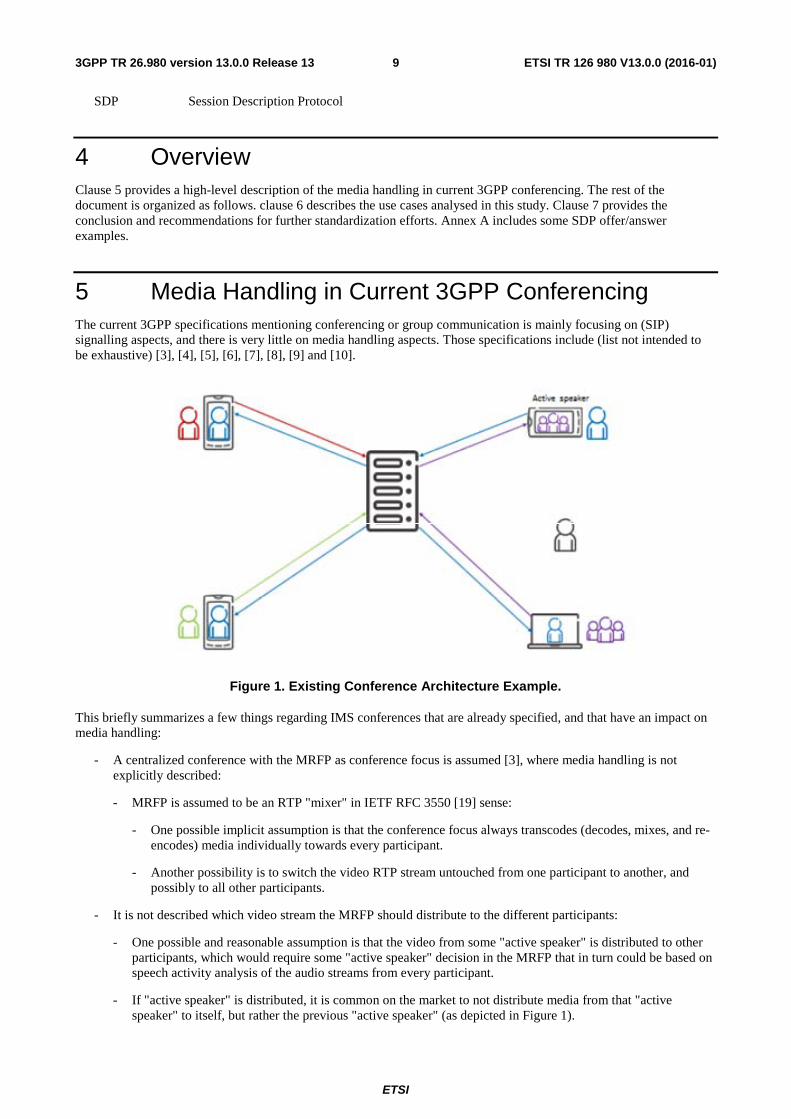
Figure 1. Existing Conference Architecture Example.
This briefly summarizes a few things regarding IMS conferences that are already specified, and that have an impact on media handling:
- A centralized conference with the MRFP as conference focus is assumed [3], where media handling is not explicitly described:
- MRFP is assumed to be an RTP "mixer" in IETF RFC 3550 [19] sense:
- One possible implicit assumption is that the conference focus always transcodes (decodes, mixes, and re-encodes) media individually towards every participant.
- Another possibility is to switch the video RTP stream untouched from one participant to another, and possibly to all other participants.
- It is not described which video stream the MRFP should distribute to the different participants:
- One possible and reasonable assumption is that the video from some "active speaker" is distributed to other participants, which would require some "active speaker" decision in the MRFP that in turn could be based on speech activity analysis of the audio streams from every participant.
- If "active speaker" is distributed, it is common on the market to not distribute media from that "active speaker" to itself, but rather the previous "active speaker" (as depicted in Figure 1).
ETSI
ETSI TR 126 980 V13.0.0 (2016-01)103GPP TR 26.980 version 13.0.0 Release 13
- Another possible assumption is that all, or at least most, participant videos are re-sized, composed, and transcoded into a checkerboard layout.
- A third possible assumption is that some type of floor control, e.g. based on Binary Floor Control Protocol (BFCP) [3] and [15], is used, where the usage details in that case are so far left unspecified.
- When MRFP is not transcoding, when changing from forwarding one participant's video to another participant's video, and since encoded video typically makes use of temporal redundancy, this change can only be made at a point in the video stream that does not depend on any previous part of that video stream – a so called "intra" picture. When deciding to make a change of forwarded video, the MRFP can trigger the UE to send such intra picture by issuing an RTCP CCM FIR command to the UE, as described in RFC 5104, and make the actual switch only when that intra picture arrives to the MRFP. Timing, reliability and bandwidth aspects of FIR transmission are described in RFC 5104. A MTSI UE is already required to support and react on FIR. When changing to a new source and if the new source is inactive (on hold or not established) then that stream has to be activated before the MRFP can switch to it.
- SIP conference call control includes three allowed options [3] and [8]:
- Each participating UE calls in to conference (SIP INVITE).
- The originating UE calls in to conference and requests it to call out to other participants (SIP INVITE with recipient list).
- A UE has an ongoing point-to-point or three-party call that is moved into a conference (SIP REFER).
- MRFC always includes "isFocus" tag in its SIP signalling [3] (regardless if it is a SIP request or response), which lets the UE know that it is signalling with a conference and not another UE.
- The conference may optionally make use of explicit floor control through Binary Floor Control Protocol (BFCP) [3] and [15]:
- The use of a floor control protocol allows explicitly, and even manually, controlling which participant's video is distributed to others by the MRFP.
- The use of this "application" media stream is negotiated through SDP [16].
- TCP transport of BFCP is assumed, possibly because this was until fairly recently the only specified transport in IETF, but many BFCP implementations on the market instead use UDP in a straightforward way, and there is well progressed work in IETF to describe this in an update to the BFCP RFC [17].
The MMCMH work item objectives include enabling multi-stream audio/video support at the terminals. In addition, as specified in the MMCMH WI objectives, the conference focus and the terminals may receive stereo streams for further processing and rendering. The clauses below present the multi-stream audio and video use cases, where the terminals receive and decode the multiple streams of audio/video and thumbnails, and render them at the terminal that is potentially transcoder-free. Conferencing using IP multimedia core network and with conference focus mixing (e.g. with MRFP) are addressed in 3GPP TS 24.147 and IETF RFC 4353.
6 Use cases
6.1 Overview This clause contains multimedia group communication use cases that enables multi-stream video and audio support at the terminals.
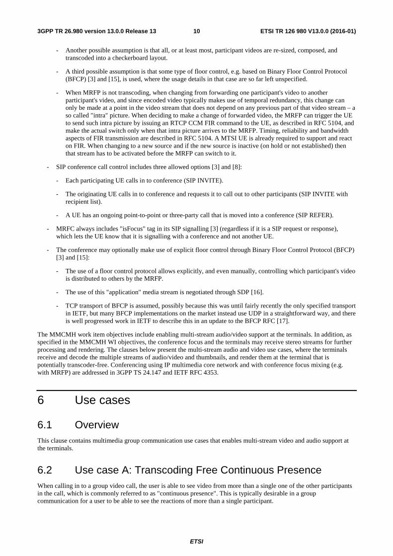
6.2 Use case A: Transcoding Free Continuous Presence When calling in to a group video call, the user is able to see video from more than a single one of the other participants in the call, which is commonly referred to as "continuous presence". This is typically desirable in a group communication for a user to be able to see the reactions of more than a single participant.
ETSI
ETSI TR 126 980 V13.0.0 (2016-01)113GPP TR 26.980 version 13.0.0 Release 13
In contrast, when receiving video from one participant at a time, several different approaches to choose that single participant are possible, subject to implementation in the conference focus. It may be that the active speaker is chosen, based on conference focus analysis of some (unspecified) voice activity measure of all participants. It may be based on a chair person's explicit and manual control of the conference focus, typically requiring a floor control protocol, such as for example BFCP, [15]. It can also be based on other approaches, such as for example an automatic, timed round-robin among all participants.
The participant layout or the number of participants simultaneously visible in a continuous presence layout is neither specified nor specifically restricted in this use case. An implementation will however always be limited, either by the receiving UE capability, or by group call network resources. Examples of receiving UE capability limitations are available display size, and decoding resources. Examples of network resource limitations are network bandwidth and conference focus processing capacity. Different UE implementations may typically have different amounts of limitation, and a solution could possibly accommodate that by letting the conference focus adapt the layout to individual UE.
Figure 2. Continuous presence example.
If the chosen layout is able to fit all participants in the group communication, no further action has to be taken. However, when the number of group participants is larger than the number of participants in the chosen layout, those participants have to be selected somehow, just as for the single video layout described above. The selection of participants to include in such continuous presence layout can be based on the same principles as for the single video case. For example, if a voice activity approach is used, the N currently most active speakers can be chosen. In that case, it is often desirable that the current active speaker is highlighted in some way, for example by using a larger video image size.
Typically, a separate composed video layout has to be created for each receiver, since it is often not desirable to show the receiving user as part of such composition. Specifically, the currently active speaker should also be shown something else than itself in active speaker position, for example the previously active speaker. If it is desirable to show a self-view video, this is much more efficient to solve locally in the sending UE, since that video then neither has to occupy any composition resources in the conference focus nor any downlink bandwidth. A video layout is possible to re-use in group communications where the total number of participants is at least two more than the number of participants included in the video layout.
The receiving user should ideally be able to impact the received layout, but it may also be decided by some policy implemented in the UE application, in the conference focus, or some combination.
6.2.1 Problem Description
Assuming that a UE can receive only a single video stream, creation of the composed "continuous presence" picture has to happen elsewhere, typically in the conference focus media handling part. Such composition requires decoding of video from all of the participants to be composed, re-sizing them to fit the layout, composing the layout in the decoded pixel domain, and re-encoding the resulting video. This transcoding operation introduces increased end-to-end delay

ETSI
ETSI TR 126 980 V13.0.0 (2016-01)123GPP TR 26.980 version 13.0.0 Release 13
and decreases video quality, similar to what is described in [11] (although that document focuses on transcoding between different video codecs). It also requires a significant amount of transcoding and video composition resources in the conference focus, per group video communication participant.
To summarize, the problem with this approach to continuous presence is threefold:
1. Increased end-to-end delay
2. Decreased video quality
3. Increased amount of resources in the conference focus
The increased bandwidth with respect to multi-stream vs. transcoding is considered in a separate use case in clause 6.4.
6.2.2 Proposed Solution
The suggested solution is instead using local video composition of decoded video in the receiving UE, meaning that it receives and independently decodes all of the video streams to be used for composition. The conference focus is then neither composing any continuous presence image nor transcoding it, but just forwarding video streams from the sending participants to appropriate receivers.
The composition can be part of the normal video display process and does not introduce any noticeable extra video delay. In addition, the video composition process is also under full control of the receiving UE, and leaves significant freedom to the local graphical user interface (GUI) to layout the different videos, and can easily (but optionally) allow the user of the receiving UE to impact such layout, without or with minimal changes to the conference focus or received video streams.
Figure 3. Transcoding-free multi-stream continuous presence example.
If the receiving UE is able to express capability for maximum number of received video streams and also their corresponding "sizes", it is fairly easy to use that information to construct meaningful local video layouts. For example, assuming that the conference focus uses voice activity detection for the group communication participants, and further assuming it is able to send videos for the N most active speakers, where the current active speaker is provided in normal resolution while the rest (N-1) is provided in low resolution ("thumbnails"). A conference focus having this information per connected UE can easily choose which, and which number of participant videos to forward to a specific UE.
To support that the active speaker is shown in normal size on receiving UE while thumbnails are smaller, the conference focus needs that active speaker to send a normal size video, while the others being shown as thumbnails may send smaller sized videos. To accommodate the previous active speaker to be shown in normal size as active speaker to the current active speaker (instead of itself), the previous active speaker may have to send both a normal sized video (to be forwarded by conference focus to current active speaker), and a small sized video (to be forwarded as thumbnail to other participants). This way of sending multiple simultaneous representations of the same content is called "simulcast" [12].

ETSI
ETSI TR 126 980 V13.0.0 (2016-01)133GPP TR 26.980 version 13.0.0 Release 13
This can be accomplished in SDP by letting the active speaker be described by the already present video m-line, and add a set of additional video m-lines (number can be decided by UE capability) to describe the additional (possibly thumbnail) videos. The advantages with this approach are that the number of and details for each additional thumbnail can be negotiated (and also rejected) independently. This approach is also fully in line with existing SDP semantics, where additional m-lines describe media that are sent in addition to and simultaneously with other m-lines (like, for example, the current audio and video m-lines).
When it comes to simulcast (see above), this is slightly different, and there is ongoing work in IETF on this issue. Different (and simultaneous) representations of the same video source should be described by a single m-line (see details in [12]). It is of course possible to express capability for and negotiate the use of simulcast.
Note that the way to implement multi-stream in this scenario does not require any specific video codec type. Any video codec type can be used, as long as the sending and receiving UE use compatible video codecs, described and negotiated by SDP, for example the mandatory TS 26.114 video codec H.264.
6.3 Use case B: Screen Sharing In a group video communication, it is sometimes desirable for a user to show something else than the video from the camera to the other participants, like a document, image or something else that can be shown on the user's local screen.
6.3.1 Problem Description
The basic problem is that there is no commonly accepted interchange format to transfer screen content between peers, although several proprietary formats do exist. It is in principle possible to send screen content as regular video, if encoding is adapted to that specific application (like, for example, high resolution and low frame rate), but general video coding is usually not optimal for the task.
It is not expected that 3GPP SA4 or the MMCMH Work Item particular could take on a task to define such format
That screen share content should also preferably be treated differently from "normal" video from a participant, such that the conference focus should not change what video to send to others based on voice activity. If it was changed based on voice activity, it would not be possible for another participant to comment on what is shown without having that commenting participant being shown instead of the screen share video. To make this distinction, the conference focus has to know this specific status of screen share video.
Typically, it is desirable to let only one participant at a time in a group communication to share its screen, which is then distributed to all other participants. In some scenarios, that can be controlled informally by regular social interaction between participants (for example using meeting audio and video communication), but in other scenarios it is preferable with more formal control by some type of meeting chair.
This problem is thus twofold:
1) The conference focus has to be able to distinguish between normal video and screen share to be able to apply another strategy what video to distribute to participants.
It should be possible to control that only a single one is sharing at any point in time, as well as who that is, and the needed formalism in this decision can differ.
6.3.2 Proposed Solution
It is noted that current HEVC extensions for screen content coding is in progress in the ISO/MPEG ITU-T JVC group. Thus, if the approach is taken to use video as screen content format, current H.264 or H.265 encoding can be used (possibly with specific encoder settings), at least as an interim solution, subject to normal UE capability negotiation, awaiting a more optimized format, like the ongoing screen content coding.
Thus, with the above assumptions, this use case can in principle be accomplished by functionality in the UE that can take video input from the UE screen instead of (or in addition to) from the camera.
To indicate the special screen share status of a video, it is proposed to adopt the approach taken by already existing equipment, using a separate video m-line in the SDP and label it with the already defined SDP "a=content" attribute [13], with a value of "slides".
ETSI
ETSI TR 126 980 V13.0.0 (2016-01)143GPP TR 26.980 version 13.0.0 Release 13
It can be noted that this is the approach taken by GSM Association in IR.39 "High Definition Video Conference (HDVC)" [14].
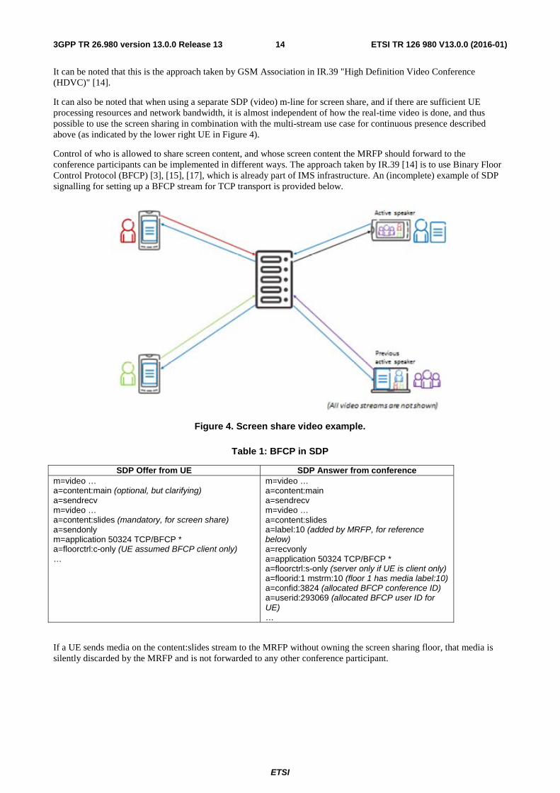
It can also be noted that when using a separate SDP (video) m-line for screen share, and if there are sufficient UE processing resources and network bandwidth, it is almost independent of how the real-time video is done, and thus possible to use the screen sharing in combination with the multi-stream use case for continuous presence described above (as indicated by the lower right UE in Figure 4).
Control of who is allowed to share screen content, and whose screen content the MRFP should forward to the conference participants can be implemented in different ways. The approach taken by IR.39 [14] is to use Binary Floor Control Protocol (BFCP) [3], [15], [17], which is already part of IMS infrastructure. An (incomplete) example of SDP signalling for setting up a BFCP stream for TCP transport is provided below.
Figure 4. Screen share video example.
Table 1: BFCP in SDP
SDP Offer from UE SDP Answer from conference m=video … a=content:main (optional, but clarifying) a=sendrecv m=video … a=content:slides (mandatory, for screen share) a=sendonly m=application 50324 TCP/BFCP * a=floorctrl:c-only (UE assumed BFCP client only) …
m=video … a=content:main a=sendrecv m=video … a=content:slides a=label:10 (added by MRFP, for reference below) a=recvonly a=application 50324 TCP/BFCP * a=floorctrl:s-only (server only if UE is client only) a=floorid:1 mstrm:10 (floor 1 has media label:10) a=confid:3824 (allocated BFCP conference ID) a=userid:293069 (allocated BFCP user ID for UE) …
If a UE sends media on the content:slides stream to the MRFP without owning the screen sharing floor, that media is silently discarded by the MRFP and is not forwarded to any other conference participant.
ETSI
ETSI TR 126 980 V13.0.0 (2016-01)153GPP TR 26.980 version 13.0.0 Release 13
The first screen sharing media a UE sends after being granted the screen sharing floorhas to be independently decodable, a "refresh point", meaning that the encoded mediawill not reference any previous media that the receivers may not have access to. An example of a refresh point is a video intra (or IDR) picture, in combination with and being preceded by the active parameter sets. The MRFP should not start forwarding screen sharing media to other receivers until a refresh point is received. If the MRFP does not receive a complete refresh point in a timely manner, a FIR should be sent towards the screen sharing UE, which should respond by including such refresh point at its earliest convenience. A UE receiving the screen share stream may similarly use FIR to ask for additional refresh points from the MRFP.
Whether or not screen sharing in the conference is moderated (by a BFCP floor chair) is a matter of conference configuration. How this configuration is made is outside the scope of the present document.
If there is a floor chair, BFCP floor requests from UE are forwarded by the MRFP to the floor chair for explicit approval, and grants or rejections are sent back to the requesting UE. If there is no floor chair, the decision to grant or reject floor requests is left to the MRFP. The details on how this decision is taken can be left to individual MRFP implementations, but possible alternatives include:
1) Always accepting new floor requests, possibly revoking the floor from a UE that is currently owning it
2) Only accepting new floor requests when no other UE owns it, requiring UE to always release the floor after sharing is done
Use of BFCP to control screen sharing can, as a simplistic alternative, also be optional. In that case, every UE that starts sending screen share media automatically gets the screen share floor, similar to either 1) or 2) above. In this case, the floor is automatically released when sending screen share media stops. In the simplest case and if this simple approach is considered sufficient, not even the MRFP needs to support BFCP. It should also be noted that without explicit floor control such as BFCP, no moderation is possible. If the MRFP supports BFCP with screen sharing, but not all UE in the conference do, the MRFP may generate BFCP floor requests and releases on behalf of the UEs not supporting BFCP, based on the simple approach above. An advantage with letting the MRFP generate BFCP requests and releases on behalf of non-BFCP UE is that the screen sharing floor can be moderated to some extent even for non-BFCP UE.
6.4 Use Case C: Bandwidth Handling This use case deal with how to control bandwidth for a UE with multistream capability in six different sub-scenarios, which must all be possible to handle and where different behaviour is needed:
a) A non-multistream capable UE calling in to a multistream-capable conference.
b) A multistream capable UE calling in to a multistream-capable conference, where the bandwidth usage desired by the UE application is less than the current network restriction (no effective limit).
c) A multistream capable UE calling in to a multistream-capable conference, where the bandwidth usage desired by the UE application is slightly greater than the current network restriction.
d) A multistream capable UE calling in to a multistream-capable conference, where the bandwidth usage desired by the UE application is significantly greater than the current network restriction (severe restrictions).
e) A multistream capable UE calling point-to-point to another multistream capable UE.
f) A multistream capable UE calling point-to-point to a non-multistream capable UE.
6.4.1 Problem Description
The number of media streams used between the conference and each individual participant UE, or point-to-point between UEs, will not exceed the UE or conference capability, andit willl thus be possible to decide through regular SDP Offer/Answer procedures.
The maximum amount of bandwidth occupied in total is limited by the available end-to-end bandwidth capacity, which is normally communicated to the UE through IMS procedures in combination with SDP Offer/Answer. This approach will be possible to use also with multiple media streams.

ETSI
ETSI TR 126 980 V13.0.0 (2016-01)163GPP TR 26.980 version 13.0.0 Release 13
The UE and the conference should each be given some reasonable amount of control over the division of this total IMS-decided total bandwidth among the different media streams, enough to be able to scale the use of multiple media streams with bandwidth availability in a way that makes sense for group video communication applications.
It will be possible to avoid using multistream functionality or additional bandwidth in cases where it is not applicable, for example in some cases when calling point-to-point.
6.4.2 Proposed Solution
This clause includes for clarification a set of example SDP fragments. It should be noted that these are not valid or complete SDP examples, but are for brevity and clarity just fragments, highlighting only bandwidth aspects of the SDP offer/answer process that are relevant to the accompanying text, and sometimes also contains clarifying comments (in brackets and italics) that would not be part of an actual SDP.
The SDP additions for multistream functionality (simulcast, thumbnails, screen sharing, and floor control; see other clauses), are all defined as SDP media-level attributes or as separate SDP m-lines, meaning that they are governed by existing SDP offer/answer rules.
6.4.2.1 Single-stream to multi-stream
If multistream functionality is not included in an SDP offer, it will also not be present in the SDP answer. The bandwidth use will then not differ from a non-multistream case, for example sub-use case a) above, where a non-multistream client calls in to a multistream-capable conference.
Table 2: Single-stream Offer to Multi-stream Conference
SDP Offer SDP Answer m=video … b=AS:500
a=sendrecv …
m=video … b=AS:500
a=sendrecv …
6.4.2.2 Multi-stream to single-stream
If multistream functionality is included in the SDP offer but rejected and disabled in the SDP answer, the negotiated bandwidth in the direction from the offerer to the answerer (in the answer) will not differ from a non-multistream case. The negotiated bandwidth in the direction from the answerer to the offerer (in the offer) is on the other hand applicable to the bandwidth needed with multistream functionality included, which will then be the bandwidth used by IMS and unnecessarily high as multistream functionality was negotiated away and will not be used.
When the offerer that offered multistream functionality learns from the SDP answer that the answerer will not make use of the multistream functionality, it can (if needed) send an updated SDP offer where the multistream functionality is disabled and the bandwidth adjusted accordingly. This second SDP offer/answer does not add to call setup time, since all media streams that are applicable to the session are already started, and the only modification needed is bandwidth allocation optimization. The resulting bandwidth use will not differ from a non-multistream case, for example in sub-use case f) above, where a multistream capable UE calls a non-multistream UE. It could be noted that in this specific point-to-point case, the offerer decision to send an updated SDP offer disabling multistream functionality can be assisted by the knowledge that it is a point-to-point call, since the "isFocus" SIP tag is not in the SIP message that carries the SDP answer.
ETSI
ETSI TR 126 980 V13.0.0 (2016-01)173GPP TR 26.980 version 13.0.0 Release 13
Table 3: Multi-stream Offer to Single-stream UE
1st SDP Offer 1st SDP Answer 2nd SDP Offer 2nd SDP Answer
m=video … (main) b=AS:500 a=sendrecv a= simulcast send p1 p2 m=video … (thumbnail 1) b=AS:80 a=recvonly m=video (thumbnail 2) b=AS:80 a=recvonly …
m=video … b=AS:500 a=sendrecv m=video 0 … m=video 0 … …
m=video … b=AS:500 a=sendrecv m=video 0 … m=video 0 … …
m=video … b=AS:500 a=sendrecv m=video 0 … m=video 0 … …
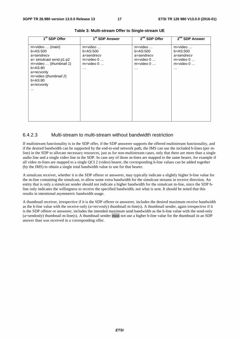
6.4.2.3 Multi-stream to multi-stream without bandwidth restriction
If multistream functionality is in the SDP offer, if the SDP answerer supports the offered multistream functionality, and if the desired bandwidth can be supported by the end-to-end network path, the IMS can use the included b-lines (per m-line) in the SDP to allocate necessary resources, just as for non-multistream cases, only that there are more than a single audio line and a single video line in the SDP. In case any of those m-lines are mapped to the same bearer, for example if all video m-lines are mapped to a single QCI 2 (video) bearer, the corresponding b-line values can be added together (by the IMS) to obtain a single total bandwidth value to use for that bearer.
A simulcast receiver, whether it is the SDP offerer or answerer, may typically indicate a slightly higher b-line value for the m-line containing the simulcast, to allow some extra bandwidth for the simulcast streams in receive direction. An entity that is only a simulcast sender should not indicate a higher bandwidth for the simulcast m-line, since the SDP b-line only indicates the willingness to receive the specified bandwidth, not what is sent. It should be noted that this results in intentional asymmetric bandwidth usage.
A thumbnail receiver, irrespective if it is the SDP offerer or answerer, includes the desired maximum receive bandwidth as the b-line value with the receive-only (a=recvonly) thumbnail m-line(s). A thumbnail sender, again irrespective if it is the SDP offerer or answerer, includes the intended maximum send bandwidth as the b-line value with the send-only (a=sendonly) thumbnail m-line(s). A thumbnail sender must not use a higher b-line value for the thumbnail in an SDP answer than was received in a corresponding offer.
ETSI
ETSI TR 126 980 V13.0.0 (2016-01)183GPP TR 26.980 version 13.0.0 Release 13
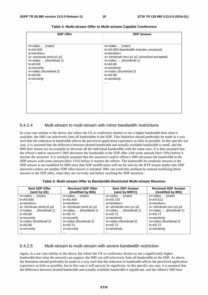
Table 4: Multi-stream Offer to Multi-stream Capable Conference
SDP Offer SDP Answer
m=video … (main) b=AS:500 a=sendrecv a= simulcast send p1 p2 m=video … (thumbnail 1) b=AS:80 a=recvonly m=video (thumbnail 2) b=AS:80 a=recvonly …
m=video … (main) b=AS:800 (bandwidth includes simulcast) a=sendrecv a= simulcast recv p1 p2 (simulcast accepted) m=video … (thumbnail 1) b=AS:80 a=sendonly m=video (thumbnail 2) b=AS:80 a=sendonly …
6.4.2.4 Multi-stream to multi-stream with minor bandwidth restrictions
In a use case similar to the above, but where the UE or conference desires to use a higher bandwidth than what is available, the IMS can selectively limit all bandwidths in the SDP. This limitation should preferably be made in a way such that the reduction in bandwidth affects the perceived application experience as little as possible. In this specific use case, it is assumed that the difference between desired bandwidth and actually available bandwidth is small, and the IMS here choses (as an example) to decrease all the individual bandwidths with the same ratio. It is thus assumed that the offerer's and/or answerer's IMS decreases the bandwidth in the SDP offer with some amount (here 10%) before it reaches the answerer. It is similarly assumed that the answerer's and/or offerer's IMS decreases the bandwidth in the SDP answer with some amount (here 15%) before it reaches the offerer. The bandwidth for sendonly streams in the SDP answer is not modified by IMS since that SDP modification will not be seen by the RTP stream sender (the SDP answerer) unless yet another SDP offer/answer is initiated. IMS can avoid this problem by instead modifying those streams in the SDP offer, when they are recvonly and before reaching the SDP answerer.
Table 5: Multi-stream Offer to Bandwidth-Restricted Multi-stream Receiver
Sent SDP Offer (sent by UE)
Received SDP Offer (modified by IMS)
Sent SDP Answer (sent by MRFC)
Received SDP Answer (modified by IMS)
m=video … (main) b=AS:500 a=sendrecv a= simulcast send p1 p2 m=video … (thumbnail 1) b=AS:80 a=recvonly m=video (thumbnail 2) b=AS:80 a=recvonly …
m=video … (main) b=AS:450 a=sendrecv a= simulcast send p1 p2 m=video … (thumbnail 1) b=AS:72 a=recvonly m=video (thumbnail 2) b=AS:72 a=recvonly …
m=video … (main) b=AS:720 a=sendrecv a= simulcast recv p1 p2 m=video … (thumbnail 1) b=AS:72 a=sendonly m=video (thumbnail 2) b=AS:72 a=sendonly …
m=video … (main) b=AS:612 a=sendrecv a= simulcast recv p1 p2 m=video … (thumbnail 1) b=AS:72 a=sendonly m=video (thumbnail 2) b=AS:72 a=sendonly …
6.4.2.5 Multi-stream to multi-stream with severe bandwidth restriction
Again, in a use case similar to the above, but where the UE or conference desires to use a significantly higher bandwidth than what the network can support, the IMS can still selectively limit all bandwidths in the SDP. As above, the limitation should preferably be made in a way such that the reduction in bandwidth affects the perceived application experience as little as possible, but in this case it will anyway be significant. In this specific use case, it is assumed that the difference between desired bandwidth and actually available bandwidth is significant, and the offerer's IMS here

ETSI
ETSI TR 126 980 V13.0.0 (2016-01)193GPP TR 26.980 version 13.0.0 Release 13
choses (as an example) to decrease a few of the bandwidths from the top of the SDP to what can be supported, and disables the last thumbnail (setting port to zero). The answerer's IMS (still as an example) has even worse conditions and reduces bandwidth even more. As for the previous example, it is not possible for IMS to disable or reduce bandwidth for RTP streams that are sendonly in the SDP answer (here thumbnails), unless an additional, subsequent SDP offer/answer is initiated. IMS can avoid this problem by instead modifying those streams in the SDP offer, when they are recvonly and before reaching the SDP answerer. How to best decrease bandwidth and/or disable streams is application-specific, included here only as an example and is not specified further. If the described methodology is followed, it can accommodate various different bandwidth-reduction approaches and be kept application-specific without requiring any changes to the UE.
Table 6: Multi-stream Offer to Severely Bandwidth-Restricted Multi-stream Receiver
Sent SDP Offer (sent by UE)
Received SDP Offer (modified by IMS)
Sent SDP Answer (sent by MRFC)
Received SDP Answer (modified by IMS)
m=video … (main) b=AS:500 a=sendrecv a= simulcast send p1 p2 m=video … (thumbnail 1) b=AS:80 a=recvonly m=video (thumbnail 2) b=AS:80 a=recvonly …
m=video … (main) b=AS:250 a=sendrecv a= simulcast send p1 p2 m=video … (thumbnail 1) b=AS:50 a=recvonly m=video 0 (thumbnail 2) …
m=video … (main) b=AS:300 a=sendrecv a= simulcast recv p1 p2 m=video … (thumbnail 1) b=AS:50 a=sendonly m=video 0 (thumbnail 2) …
m=video … (main) b=AS:250 a=sendrecv a= simulcast recv p1 p2 m=video ... (thumbnail 1) b=AS:50 a=sendonly m=video 0 (thumbnail 2) …
6.4.2.6 Multi-stream UE to multi-stream UE in point-to-point
The multi-stream capable UE sending the SIP INVITE cannot in general be assumed to know whether it will be talking to a conference or not before making the call, and will thus include its multi-stream capabilities in the SDP offer. It has been shown above that this will not have any negative impact if the called UE is a single-stream UE, since it will disable all non-supported functionality in the answer. If the called UE is a multi-stream UE, it does have capabilities corresponding to those in the offer, and could in principle enable the multi-stream also point-to-point. There would however hardly be any point in sending different simulcast versions between UEs, and there would also hardly be any use for thumbnails, so both of those should be disabled in the UE-to-UE case.
One way to distinguish this situation is to look at the presence of the "isFocus" tag in the SIP header. A conference will include this tag, but a UE will never include it. The UE receiving the SIP INVITE can therefore know that the call is not coming from a conference and can therefore safely disable all multi-stream functionality that does not make sense to use point-to-point between UE. The UE that sent the SIP INVITE can also see from the SIP response that the other party is not a conference, and know that is the reason for disabling multi-stream functionality. If the SIP response does not include the "isFocus" tag, and if multi-stream functionality is not disabled in the SDP answer, the offerer should probably use multi-stream functionality with some caution, if at all, under the assumption that the remote UE did not correctly handle the SDP offer/answer with the multi-stream functionality included and therefore generated an incorrect SDP answer.
A valid SDP example for this case will look the same as in Table 3 above.
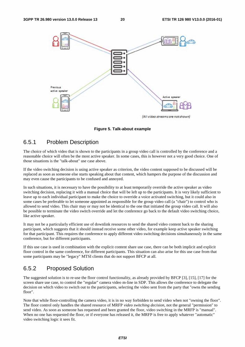
6.5 Use Case D: Active Speaker Override While in a group video call, one of the participants wants to show something specific to the entire group and let the group discuss about it, while everyone sees that same video. In Figure 5 below, the top right UE is the one sharing its video (of the car) to the others, but the lower right UE is the one that is active speaker (commenting what is shown). This is similar to a screen share situation (described in Use Case B), but uses a regular video camera instead of sending the contents of a screen. It should be possible for the user of the sending UE to understand when and if the video it is sending is forwarded to the other participants. It should also be possible for the user of the sending UE to see the reactions to the shared video by receiving a regular voice activated video from the other participants in the group.
ETSI
ETSI TR 126 980 V13.0.0 (2016-01)203GPP TR 26.980 version 13.0.0 Release 13
Figure 5. Talk-about example
6.5.1 Problem Description
The choice of which video that is shown to the participants in a group video call is controlled by the conference and a reasonable choice will often be the most active speaker. In some cases, this is however not a very good choice. One of those situations is the "talk-about" use case above.
If the video switching decision is using active speaker as criterion, the video content supposed to be discussed will be replaced as soon as someone else starts speaking about that content, which hampers the purpose of the discussion and may even cause the participants to be confused and annoyed.
In such situations, it is necessary to have the possibility to at least temporarily override the active speaker as video switching decision, replacing it with a manual choice that will be left up to the participants. It is very likely sufficient to leave up to each individual participant to make the choice to override a voice activated switching, but it could also in some cases be preferable to let someone appointed as responsible for the group video call (a "chair") to control who is allowed to send video. This chair may or may not be identical to the one that initiated the group video call. It will also be possible to terminate the video switch override and let the conference go back to the default video switching choice, like active speaker.
It may not be a particularly efficient use of downlink resources to send the shared video content back to the sharing participant, which suggests that it should instead receive some other video, for example keep active speaker switching for that participant. This requires the conference to apply different video switching decisions simultaneously in the same conference, but for different participants.
If this use case is used in combination with the explicit content share use case, there can be both implicit and explicit floor control in the same conference, for different participants. This situation can also arise for this use case from that some participants may be "legacy" MTSI clients that do not support BFCP at all.
6.5.2 Proposed Solution
The suggested solution is to re-use the floor control functionality, as already provided by BFCP [3], [15], [17] for the screen share use case, to control the "regular" camera video m-line in SDP. This allows the conference to delegate the decision on which video to switch out to the participants, selecting the video sent from the party that "owns the sending floor".
Note that while floor-controlling the camera video, it is in no way forbidden to send video when not "owning the floor". The floor control only handles the shared resource of MRFP video switching decision, not the general "permission" to send video. As soon as someone has requested and been granted the floor, video switching in the MRFP is "manual". When no one has requested the floor, or if everyone has released it, the MRFP is free to apply whatever "automatic" video switching logic it sees fit.

ETSI
ETSI TR 126 980 V13.0.0 (2016-01)213GPP TR 26.980 version 13.0.0 Release 13
By re-using BFCP functionality from screen share, the controlling party could either be each individual participant, or requests could alternatively be moderated by a floor chair. BFCP supports multiple floor handling, and camera share and document share simply use different floor identifications, which are communicated through SDP and can be used in BFCP signalling to choose which video to control.
The floor handling controls should be an integrated part of the video call UI, and could possibly be shown to the user only when in a group call, since the "isFocus" tag in SIP signalling [3] in combination with BFCP capability in SDP received from the remote party indicates this to the UE.
In the simplest controlled case, leaving floor control to the participants as a group, the conference always accepts all requests to become video sender. Any new request will automatically revoke any previous owner of the floor and replace it with the sender of the new request. It is likely that this approach will work well in most group video calls, leaving the control of who is sending to be based on regular social interaction among the group participants.
A UE that is granted the floor, as indicated through the BFCP "Granted" response, can indicate to the user in the graphical user interface that its video is now being seen by everyone. When the UE owning the floor releases it, the conference changes back to use the default switching principles, like voice activated.
The conference could also be configured (by means not yet specified here) to be moderated, in which case all requests for the "sending floor" will be explicitly granted or denied by an appointed floor chair. The chair can of course grant the floor also to itself. Otherwise, the functionality is the same as above.
The MRFP has to know which participant that currently owns the "sending floor", which makes it possible to apply a different video switching decision to that participant, not sending back the shared video content. Active speaker video switching is instead kept for that participant, enabling to show voiced reactions from other participants to the shared video content.
It should be noted that while current 3GPP specifications only refer to IETF RFC [15], [16] where TCP is used as BFCP transport, industry best current practice for BFCP is to use UDP transport and there are well progressed Internet Drafts for this [17], [18]. One of the key benefits when using UDP is the ability to leverage existing NAT traversal infrastructure, as described in Appendix B of [17]. Multi-stream MTSI UE should use UDP transport for BFCP according to those specifications, but may in addition support TCP transport. It would be preferable to update 3GPP specifications to allow for BFCP UDP transport.
The example below shows an SDP signalling fragment that hints how to enable the active speaker override functionality based on BFCP, including BFCP-controlled screen share to show their relation and identification:
Table 7: Active Speaker Override in SDP
SDP Offer from UE SDP Answer from conference m=video … a=content:main (optional, but clarifying) a=sendrecv m=video … a=content:slides (mandatory, for screen share) a=sendonly m=application … UDP/BFCP * a=bfcpver:1 2 (version 2 needed in list for UDP) a=floorctrl:c-only (UE assumed BFCP client only) …
m=video … a=content:main a=label:10 (added by MRFP, for reference below) a=sendrecv m=video … a=content:slides a=label:11 (added by MRFP, for reference below) a=recvonly a=application … UDP/BFCP * a=bfcpver:1 2 (also supports versions 1 and 2) a=floorctrl:s-only (server only if UE is client only) a=floorid:1 mstrm:10 (floor 1 has media label:10) a=floorid:2 mstrm:11 (floor 2 has media label:11) a=confid:3824 (allocated conference ID) a=userid:293069 (allocated UE user ID) …
The single BFCP m-line can handle multiple, separate floors. Each m-line to be controlled by BFCP has an associated "a=label:<x>" attribute with a unique but arbitrarily chosen value <x>.
Those label <x> values are related to BFCP floor identifications <y> through "a=floorid:<y> mstrm:<x>" attributes under the BFCP m-line. The BFCP floor identification values are used in the BFCP signalling stream between the UE and the MRFP when requesting and granting floors for the related media streams. The <x> and <y> identifiers may be chosen freely by the MRFP.

ETSI
ETSI TR 126 980 V13.0.0 (2016-01)223GPP TR 26.980 version 13.0.0 Release 13
This simple use of BFCP has very limited use of the "a=confid" and "a=userid" BFCP attributes, but the BFCP specification recommends that they are always included. The identifier values for those attributes may also be chosen freely by the MRFP, as long as each UE is given a unique userid value in the conference, and the same confid value is used for all UE in the conference.
The "a=bfcpver" attribute is needed when BFCP version 2 is used, which is in turn required for BFCP UDP transport.
6.6 Use Case E: Pausing Unused Streams While in a group video call using switched multi-stream in combination with simulcast, and if there are more participants in that call than what can be shown simultaneously as active speaker and thumbnails on the receiving UEs, the MRFP will at every point in time have some video streams that are not switched to any receiving UEs. Figure 6 below shows an example time instant of such group video call, showing all video streams in the call, marking the non-needed as dotted and therefore the ones desirable to pause. It could be noted that there will be an increasing number of paused streams with increasing number of participants, which also means that pausing improves scaling of total conference resource consumption with the group call size.
In this use case, it is only the MRFP that has the need to pause and resume streams, and only the MRFP has the information on which streams are needed or not. This also means that pause/resume operation is only needed for uplink streams. A different set of streams will be switched to receiving UE when active speaker changes, which is depicted in Figure below.
Figure 6. Pausing Example

ETSI
ETSI TR 126 980 V13.0.0 (2016-01)233GPP TR 26.980 version 13.0.0 Release 13
Figure 7. Pausing Example After Active Speaker Change
Some streams that were paused are now needed and must be resumed. Other streams that were previously needed can now be paused. For most streams, the pause/resume status is not changed, but the origin of the stream (shown as different colour) may have changed.
6.6.1 Problem Description
When the MRFP detects that active speaker has changed, the video stream from previous active speaker should no longer be forwarded as active speaker video to the group participants, and the video stream from the new active speaker should instead be used as active speaker video stream. If the video stream from this new active speaker was paused, it will now be resumed. It is assumed that the group participants want to see this new active speaker as soon as possible. The time from when the MRFP detects the new active speaker until it is shown on the receiver's displays should thus be minimized.
It would be possible to use the existing signalling channel between the UE and the MRFP and send SIP UPDATE from the MRFP, changing directionality of the affected streams. Pausing a sendrecv stream in SDP from the UE would become a sendonly stream in the updated MRFP offer, which in SIP is indistinguishable from putting the stream on hold [24].
This ambiguity in what type of pause is wanted is not desirable, and may even risk that the UE treats the call as on hold.
Holding a call typically lasts for some time, and it is reasonable for a UE to then close and release at least some of the most battery-consuming transport and codec resources. Resuming a call on hold is also typically not time critical, and it would be acceptable for the UE to for example re-initialize the camera and re-instantiate and re-initialize the video codec. The type of pause described in this use case however requires a more "hot" pause operation, where the UE is prepared for a low latency resume.
The frequency of such active speaker-triggered SIP UPDATE between MRFP and most group call participants could also be fairly high, like up to once every few seconds. This is at least significantly higher than the average time between group participants leaving or joining the call, which is probably otherwise the cause of most MRFP SIP signalling load. The amount of SIP/SDP information required on the signalling bearer will be significantly increased compared to when pause / resume is not used in this way, especially since multi-stream SDP can be significantly larger than without multi-stream. This may even impact ongoing media quality negatively due to the signalling bearer having higher priority than media.
An additional drawback with using SIP UPDATE and SDP is that current simulcast specification sends all simulcast versions under the same m-line, and it is not possible to change direction for individual streams, only for the entire m-line.

ETSI
ETSI TR 126 980 V13.0.0 (2016-01)243GPP TR 26.980 version 13.0.0 Release 13
Some of the uplink thumbnail simulcast streams may also have to be resumed when changing active speaker, due to that they were not previously viewed by any receiving UE, but that they are now desirable to show as thumbnail on some UE (replacing some other thumbnail, for example one that was quiet for a longer period of time). The desirable timing for such thumbnail change is almost as strict as the active speaker change described above, and the frequency of pausing and resuming thumbnails as seen from a single UE-MRFP connection may be even higher than active speaker changes.
All of the above suggests that using the currently available signalling channel between the UE and the MRFP, SIP UPDATE, is not any ideal solution to pause / resume streams, and another, faster and less resource-demanding solution should be found.
6.6.2 Proposed Solution
The suggested solution is to use RTP pause / resume as described by [23], which implements the pause / resume signalling as RTCP feedback messages. This has no SIP/SDP signalling impact on active speaker changes, and thus provides a resource efficient and sufficiently fast signalling solution.
This is an SDP signalling fragment example that hints how to negotiate this pause / resume functionality:
Table 8: Pause / resume in SDP
SDP Offer from UE SDP Answer from conference m=video … a=rtcp-fb:* ccm pause nowait …
m=video … a=rtcp-fb:* ccm pause nowait …
The fact that the "ccm pause" is present in the SDP answer means that RTCP pause / resume signalling can be used for the streams related to the affected m-line.
The "nowait" parameter tells the remote peer that the party sending the SDP believes the pause operation can take effect immediately, without concerns that there may be more simultaneous receivers of the stream than the MRFP that do not want to pause it. This is effectively always true when UE and MRFP are connected point-to-point (see [23] for further details), which is a situation that should in general be known by the UE and the MRFP. If "nowait" is present in SDP offer and answer, both ends believe they are connected point-to-point, there is no need to apply the hold-off delay described in [23], and pausing can thus occur immediately. Opposite examples, when MRFP and UE are not effectively point-to-point, could be when the MRFP implements an RTP Translator topology, or when the MRFP is connected to the UEs via an IP multicast network.
The MRFP may optionally not implement the ability to pause its own streams on peer request, but just include the functionality to pause the UE's streams. The UE may similarly and optionally not implement the ability to pause a peer's (like the MRFP) streams, but just include the functionality to pause its own streams. This type of limited configuration can also be negotiated in SDP, through the use of an optional "config" parameter to the "ccm pause" line:
Table 9: Pause / resume with limited configuration in SDP
SDP Offer from UE SDP Answer from conference m=video … a=rtcp-fb:* ccm pause config=3 nowait …
m=video … a=rtcp-fb:* ccm pause config=2 nowait …
If the UE specifies config=3 in the offer, it means that the UE can receive pause and resume requests and act on them, but will not send those requests itself. In this case, the SDP answer from the MRFP contains the "opposite" functionality and configuration, config=2.
It is recommended that both UE and MRFP implement full pause / resume capability (corresponding to "config=1", which is default if no "config" is included on the "ccm pause" line). A UE may optionally instead implement config=3, and an MRFP may optionally instead implement config=2.
ETSI
ETSI TR 126 980 V13.0.0 (2016-01)253GPP TR 26.980 version 13.0.0 Release 13
6.7 Use Case F: Conference Rate Adaptation Considerations While in a group video call using switched multi-stream, either uplink or downlink streams (or both) may experience channel capacity variations, requiring rate adaptation to keep within the channel limits and avoid packet loss and/or increased delay for media carried by the affected streams.
6.7.1 Problem Description
For the case when the conference MRFP performs individual transcoding for every MRFP-UE downlink, all downlink rate adaptations are independent and accounts only for the local downlink channel variations. When instead using video switching to avoid video transcoding in the MRFP, this also limits the possibility to do per-link rate adaptation to individual group participant UEs. Rate adaptation in a group call will therefore in principle be made end-to-end, instead of separately UE-to-MRFP and MRFP-to-UE. This poses a potential problem, since there are typically multiple receivers of the same, switched, video stream. There is also potentially a conflict of interest between UE receivers with different conditions that all want as good quality as possible, matching exactly their (end-to-end) channel.
When using multi-stream, there may be multiple streams sharing the same (varying) channel resources (bearer). Those resources will thus be distributed dynamically to the different streams in a way that avoids exceeding the total available channel capacity.
6.7.2 Proposed Solution
It is suggested to keep some separation of uplink (UE-MRFP) and downlink (MRFP-UE) in rate adaptation, letting the MRFP be involved in rate adaptation to the extent possible and feasible.
When rate adaptation is needed on the UE-MRFP uplink, this is basically the same as a point-to-point call from a rate adaptation perspective. The media quality resulting from rate adaptation on the uplink is then the starting point for any rate adaptation necessary on the downlink. Naturally, no received downlink media stream can be any better than what was achieved on the uplink, regardless of the individual downlink quality.
When the conference MRFP uses video switching to the largest extent possible, the same video streamwill fit all downlinks simultaneously. The aggregate rate adaptation feedback information from the MRFP to the stream sender will then have to reflect the worst observed UE-to-UE path.
An example of this is depicted in Figure 8 below, where the stream sender is located bottom right in the picture, and the affected receivers are top and bottom left. Rate adaptation feedback is indicated by a dashed arrow, and the related media stream is indicated through a dashed loop connected to the signalling arrow.
If there is a very large difference between a (few) worst path(s) and the other ones, the worst path(s) would affect many receivers to an unreasonably large extent. It may be possible to avoid this unwanted situation by letting the MRFP dynamically apply transcoding only towards downlink receiving UE that experiences particularly bad channel conditions.
Another way of avoiding unwanted quality degradations to downlink receivers with good channel conditions because there are other downlink receivers with much worse channel conditions is to utilize simulcast streams. If the stream that needs rate adaptation has a lower quality simulcast version, and if the needed rate adaptation is so substantial that the resulting quality would be similar to the lower quality simulcast version, the MRFP could simply switch the lower quality simulcast version to the UE that experiences bad channel conditions. An example of this is depicted in Figure 9 below.
As with the previous figure, rate adaptation feedback is indicated by a dashed arrow, and the related media stream is indicated through a dashed loop connected to the signalling arrow. A few things could be noted:
- There are no other receivers of the "large" simulcast version from the bottom right sender, but if there were, they would not have been affected by the upper right receiver no longer using it.
- The uplink rate adaptation of the "large" simulcast version is not affected by the MRFP rate adaptation decision to no longer use it.
- The upper right receiver is now instead receiving the "small" simulcast version, and any further rate adaptation needed to that version from either one of the other, left, receivers, will affect all receivers, as was described above.

3GPP TR 26.980 version 13.0.0 Release 13
- If the channel conditions for the upperthe "large" simulcast version, possibly
Figure 8. W
Figure 9. S
If downlink channel conditions towards a UEleast temporarily pause (similar but not identisharing the affected channel resource. This dodepicted in Figure 10 below, where both "thu
ETSI
ETSI TR 126 980263
er right receiver improve considerably, the MRFP could gly amended with the method described in Figure 8 above.
Worst Path Rate Adaptation Example
Simulcast Rate Adaptation Example
E become really bad, there is of course always a possibilintical to Video Use Case in clause 6.6) one or more downl does not impact other receivers of those streams. An examhumbnails" are (temporarily) stopped to the upper right re
80 V13.0.0 (2016-01)
d go back to sending ve.
bility to stop or at nlink streams ample of this is
receiver.

ETSI
ETSI TR 126 980 V13.0.0 (2016-01)273GPP TR 26.980 version 13.0.0 Release 13
Figure 10. Pruning Rate Adaptation Example
When the channel situation improves, the stopped/paused streams can be resumed again.
When multiple streams share a common channel resource, it is expected that the UE can know this and adapt the rate adaptation feedback information for the affected streams such as not to exceed the shared resource. When using TMMBR/TMMBN as rate adaptation feedback, the decision of bitrate allocation to individual streams (stream "priority") will be left to the receiving UE, since TMMBR/TMMBN scope is a single stream, not the entire shared resource. This is believed to be sufficient, until proven otherwise. A "joint" rate adaptation would require another rate adaptation technology and/or feedback format.
All rate adaptation aspects described above can be used in the same conference, some even simultaneously, subject to MRFP implementation and available channel conditions towards individual receiving UE.
6.8 Use Case G: Multi-stream Audio Steering or Panning Figure 11 shows an example use case where the audio from conference participants are directed or steered such that it appears that the participants A, B, and C are spatially distributed in a particular configuration. Head-related transfer function (HRTF) tools can be used to perform audio panning at the rendering device. Audio panning may reduce the fatigue to the participant D where the simultaneous talking of e.g. participant A and C is easily distinguished through spatial steering of audio. Audio panning may also enable the rendering device to choose to naturally vary the audio levels of participants before HRTF mixing. For example, participant D may prefer to give more importance to participant A's audio relative to participants B and C and selectively adjust the mixing gains in the personalized HRTF functions. In one example, the participant D may completely mute all participants except participant A during multiple active talkers. This achieves the same functionality as in Video Use Case D without requiring use of a conference focus, see clause 6.5. Further, participant D may also signal to the conference focus to manage the bit rate and audio bandwidth SDP negotiations based on talker preferences and depending on the rendering device capabilities.
Figure 12 shows a block diagram with decoded audio streams of talkers A, B, and C processed using the HRTFs. The HRTFs may be pre-computed based on a preferred virtual speaker location assignment. For example, the HRTF_A function may steer spatially the talker A's audio stream to be perceived to arrive from the left side (e.g. as shown in Figure 11). Similarly, HRTF_B and HRTF_C steer the talker B's and talker C's audio spatially to arrive as shown in Figure 11. The HRTFs may also include gain control to emphasize a preferred talker relative to others.
3GPP TR 26.980 version 13.0.0 Release 13
Figure 11. Audio panning of p
Figure 12. Multi-stream audio from pparticipa
6.9 Use Case H: De-jiFigure 13 shows a block diagram where multiconference focus will be equipped with multipsequential order (e.g. based on RTP_A, RTP_and re-encoding. At the rendering device the rthe conference focus may contribute to increaat both the conference focus and at the render
Furthermore, as described in MMCMH videoaudio is mixed/transcoded as per Figure 13 atvideo and audio streams may become a challecompensation for Audio and Video stream syat the rendering device. On the other hand, if the principles of 3GPP TS 24.147 are followe
Figure 14 shows a block diagram where multitimestamps unchanged by the conference focuthe receiving UE. This is in contrast to the scejitter buffer delays twice – once at the conferemedia handling at the rendering devices providetermine a desired bit rate per talker and HR
ETSI
ETSI TR 126 980283
f participants A, B, and C and rendering to partici
m participants A, B, and C are mixed at the renderipant D using personalized HRTFs.
jitter Buffer Handling ultiple audio stream RTP packets are received at the confeltiple de-jitter buffers to handle the multiple RTP audio paP_B, and RTP_C packet timestamps) for decoding and sue received mixed audio is decoded and played out. In effe
reased JBM delay along with transcoding delays. In additiering device will meet the TS 26.114 delay requirements.
eo use cases, if the multiple streams of video are not transat the conference focus, the aforementioned delay adjustmllenging problem. In such case, the logic for JBM and tran
synchronization may have to be performed both at the con if both video and audio streams are transcoded at the confwed.
ultiple audio stream RTP packets are received at the rendeocus. In this case, packets are exposed to de-jitter buffer descenario in Figure 13, where packets from a single stream erence focus, and once in the receiving UE. The MMCMHovides flexibility, based on the jitter and network delay ch
RTF mixing scenarios.
80 V13.0.0 (2016-01)
icipant D.
ering device of
ference focus. The packets and send in a subsequent mixing ffect, audio mixing at ition, the JBM design ts.
nscoded, while the stment between the transcoding delay onference focus and nference focus, then
dering device with r delays only once at m are exposed to de-H video and audio
characteristics, to

3GPP TR 26.980 version 13.0.0 Release 13
Figure 13. De-jitter buffer cont
Figure 14. De-jitter buffer cont
6.10 Use Case I: AudioFigure 15 shows an example use case where ttracking tools at the rendering device. The hefunctions to rotate the sound field as shown in
As shown in Figure 16, for audio spatializatioindividual talkers seating location.
ETSI
ETSI TR 126 980293
ntrol at the conference focus and at the rendering
ntrol at the rendering device with multiple audio
dio Spatialization based on head-te the audio from conference participants are steered basedhead-tracking information, for example, can be integrated in Figure 16.
tion, the head-tracking information can be taken into acco
80 V13.0.0 (2016-01)
ing device
io streams
tracking sed on the head ed into the HRTF
count along with the
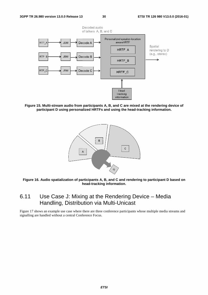
3GPP TR 26.980 version 13.0.0 Release 13
Figure 15. Multi-stream audio from pparticipant D using personal
Figure 16. Audio spatialization of parh
6.11 Use Case J: MixinHandling, Distribu
Figure 17 shows an example use case where tsignalling are handled without a central Confe
ETSI
ETSI TR 126 980303
m participants A, B, and C are mixed at the renderalized HRTFs and using the head-tracking inform
articipants A, B, and C and rendering to participahead-tracking information.
xing at the Rendering Device – Mebution via Multi-Unicast
e there are three conference participants whose multiple mnference Focus.
80 V13.0.0 (2016-01)
ering device of rmation.
ipant D based on
Media
e media streams and

3GPP TR 26.980 version 13.0.0 Release 13
Figure 17. Multi-stream media handlingenable m
Clause 6.4 of [25] describes three media distrmulti-unicast, multicast, and single-source musubclauses.
6.11.1 Concurrent Codec C
6.11.1.1 Concurrent Decoding
Media distribution via multi-unicast requires received from the other conference participaninstances it can operate concurrently. This limterminal, or requires that the terminal has the
Let,
- MaxDec be the maximum number of
- N be the number of participants in th
If a terminal does not ignore any media stream
N <= Ma
When sending an SDP Offer, the conference icallers to invite to the conference (i.e. N-1).
Furthermore, if each of the other terminals doalso be able to decode N-1 media streams. Th
N <= min(MaxDec
6.11.1.2 Concurrent Encoding
Media distribution via multi-unicast can requiare sent to the other participants. This can hapand the other participants select to use differe
This is illustrated in Figure 18 below where teterminals B and C. Terminal C supports EVS
ETSI
ETSI TR 126 980313
ing in a conference with media routed to the rend mixing to be performed at the UEs.
stribution models where distributed mixing is performed i multicast (SSM). Each of these models is analysed further
Capabilities Exchange
ing
es that a UE concurrently decode multiple audio and/or vidants. Each terminal has a computational limit to the numblimits the number of participants that can be in a conferenche ability to prioritize decoding certain streams and ignore
of decoders that can be run concurrently by the terminal
the conference, including the conference initiator
eams it receives then
MaxDec + 1 E
e initiator should respect the above limitation when decidi
does not prioritize and ignore media streams it receives, eTherefore the initiator has to consider the following limita
of each terminal) + 1 E
ing
quire that a UE concurrently encode multiple audio and/orhappen when the initiator offers more than one type of coderent codecs.
e terminal A has offered both EVS and AMR-WB in its SDS and responds with an SDP answer selecting EVS while
80 V13.0.0 (2016-01)
ndering devices to
d in a conference: her in the following
video streams ber decoder
ence with the ore others.
Eq. 6.11.1-1
iding how many
, each terminal will itation:
Eq. 6.11.1-2
/or video streams that odec for a media type
SDP offers to ile terminal B, which

ETSI
ETSI TR 126 980 V13.0.0 (2016-01)323GPP TR 26.980 version 13.0.0 Release 13
only supports up to AMR-WB, selected AMR-WB in its SDP Answer to terminal A. Terminals B and C also perform their own codec negotiation (e.g. set-up via the SIP REFER method from terminal A) in which they choose AMR-WB since terminal B does not support EVS.
Figure 18. Multi-stream audio handling with audio routed to the rendering device and audio mixing performed at the UE using different negotiated codecs.
As can be seen from Figure 18, Terminal A and Terminal C have to both encode their content in the EVS and AMR-WB formats concurrently.
Let, MaxEnc be the maximum number of encoders that can be run concurrently by the terminal.
Then a terminal initiating a conference with in-terminal mixing should consider the following limit:
min[# of types of codecs in the SDP offer, (N-1)] <= MaxEnc Eq. 6.11.1-3
Furthermore, as was seen in the previous example, the # of types of codecs will also be less than the MaxEnc of each terminal involved in the conference. Therefore the following limit should be followed:
min[# of types of codecs in the SDP offer, (N-1)] <= min(MaxEnc of each terminal) Eq. 6.11.1-4
6.11.1.3 Further Considerations in Concurrency
In a practical terminal implementation, the constraints described in clauses 6.11.1.1 and 6.11.1.2 must take into account that:
- For a given media type, the different types of codecs have different computational complexity requirements. This requires that the conference initiator consider the following for each codec it includes in the SDP Offer:
min(MaxEnc of each codec) and min(MaxDec of each codec) Eq. 6.11.1-5
- A terminal performs both encoding and decoding. If these processes run on the same processors then the MaxEnc and MaxDec will depend on how many instances of each operation (encode/decode) are running. Conceptually, the limitation can be generalized as follows:
complexity(operational encoders + operational decoders) <= complexity limit Eq. 6.11.1-6
A’s media to C
EVSB’s m
edia to
C
AMR-
WB
C’s media to A
EVS
C’s m
edia to
B
AMR-
WB
ETSI
ETSI TR 126 980 V13.0.0 (2016-01)333GPP TR 26.980 version 13.0.0 Release 13
- A terminal in a video conference performs both audio and video coding. If these processes run on the same processors then the MaxEnc and MaxDec will depend on how many instances of each operation for each media type are running. Conceptually, the limitation can be generalized as follows:
complexity(operational audio codecs + operational video codecs) <= complexity limit Eq. 6.11.1-7
6.11.1.4 Prioritizing and Ignoring of Received Media Streams
A terminal can extend its ability to handle a conference with N users even if
N > min(MaxDec of each terminal) + 1 Eq. 6.11.1-8
as long as the terminal and all the other terminals in the conference do not decode all of the media streams they receive. This requires that the terminals have a means for choosing which streams to prioritize and which ones to ignore.
In the case of speech, this selection could be made based on which streams are not in DTX mode. In most cases, talkers will naturally floor control each other as it is difficult to listen to more than two speakers at the same time. Therefore a terminal that can decode up to two or three concurrent audio streams could handle most audio conference configurations. However, it should be noted that there will still be some operational complexity increase with increasing N as the terminal has to inspect the voice packets (at least for size) from the media streams to determine which are active.
It is also possible for the terminal to attempt to prioritize the media streams with the loudest volumes. However, this requires decoding of the media from each stream to determine the loudest MaxDec streams. The terminal could save some complexity if the sampling/selecting is not performed for every voice frame, e.g. periodically at longer intervals.
For video, it is not as simple to dynamically select which streams to prioritize and ignore as there are not the same concepts of DTX and volume. Looking at other criteria such as the amount of movement will involve significant complexity. Simpler criteria such as looking at the size of video packets might be used to get a very rough idea of motion/new information in particular video streams.
Video has the additional challenge that most of the frames in the streams are differentially encoded wrt previous video frames in the stream. If a media stream is ignored it cannot simply be decoded again until an independently-decodable (e.g. IDR) frame, or a frame whose reference frame has already been pre-stored, is received.
6.11.1.5 Conclusions
When sending the SDP Offer for a conference that has in-terminal mixing, the conference initiator needs to consider, its computational constraints, i.e. the maximum number of concurrent encoders and decoders the conference initiator can operate. Before sending the SDP Offer, the conference initiator should also be informed of the computational constraints of the other conference participants, i.e. the maximum number of concurrent encoders and decoders each terminal can operate, and take these constraints into account.
6.12 Use Case K: Mixing at the Rendering Device – Media Handling, Distribution via Multicast
In a multicast model, each participant joins a common multicast group, and each participant sends a single copy of its media stream to that group. The underlying multicast infrastructure then distributes the media, so that each participant gets a copy.
The advantage of this distribution model over multi-unicast is that it does not require the sending terminal to send individual copies of the media to each of the other (N-1) participants. This could provide a big savings on the uplink capacity, uplink coverage, and terminal battery life for conferences with large N.
NOTE 1: FFS is the potential delay incurred by participants subscribing and setting up the multicast tree to receive media.
NOTE 2: Architectural impacts due to multicast need to be checked with SA2.
ETSI
ETSI TR 126 980 V13.0.0 (2016-01)343GPP TR 26.980 version 13.0.0 Release 13
6.12.1 Session Establishment
6.12.1.1 In the presence of a Conference Focus
If a Focus was involved in session establishment of a multicast session, the conference focus would convey the same information as the conference initiator, albeit with possibly different signalling methods. For example, the conference focus will initiate the dialog with N participants to set up a conference, but the session description associated with the dialog will allow media to be distributed via multicast to all the participants. The multicast IP addresses (public or private) associated with the multicast groups for each of the mandatory and recommended codecs are selected and assigned by the conference focus. The security considerations are handled by the conference focus through SIP authentication mechanisms.
6.12.2 Media Handling
6.12.2.1 In the absence of a Conference Focus for media handling
As multicast groups were designed primarily for streaming applications, some additional media handling needs to be specified when using this topology for conferencing.
If a terminal supports more than the mandatory codec(s) for a particular media type and wishes to receive media on the optional codec(s) then, as described in the previous clause, it will also register to receive the media in a multicast group carrying a mandatory codec. If more than one mandatory codec is offered by the conference initiator there are two possibilities for the participants:
1) Each listening participant has to register to listen to all the multicast groups carrying media from the mandatory codecs. When sending media, each sender only has to encode media using one of the mandatory codecs and send this media over the corresponding multicast group.
2) Each listening participant only has to register for one multicast group carrying media from one of the mandatory codecs. When sending media, each sender has to encode media using all of the mandatory codecs and send the media on all their corresponding multicast groups.
The second approach increases the encoding load for the sender while decreasing the decoding load of the receivers and is generally less desirable than the first approach as encoding is computationally more taxing than decoding.
Since media is always going to be sent on the mandatory multicast groups and all terminals will listen to these groups, no terminal is ever required to encode media using the optional codecs and their multicast groups. Even the conference initiator does not have to encode media using the optional codecs for which it has established and offered a multicast group to the other participants. However, terminals that are capable of concurrently encoding both a mandatory and optional codec should still encode using the optional codec if it provides better quality.
For each multicast group a terminal is listening to, the terminal should examine the sources (e.g. source IP address) of the media to determine which traffic is coming from the same participant and avoid decoding multiple versions of media coming from the same source. The terminal should compare the source information to any media received from other multicast groups it is listening to. If there is duplication of media representations, i.e. media coming from the same source with the same RTP timestamp or sequence number, the terminal should choose to decode the media from one of the codecs, preferably the one that offers the best quality. This choice could change on a per-frame-frame basis in the event that some loss is experienced for packets traversing through different multicast trees.
Once the media packet is chosen, the terminal should perform de-jitter buffering on that packet in relation to previously chosen packets for that media type from the same participant, but not necessarily the same codec type. Note that this switching of codec types being fed into the de-jitter buffer requires that the codec information is also maintained in the de-jitter buffer operation to ensure proper decoding after de-jittering.
Listening terminals will also examine the source of the media received to avoid decoding its own media when the terminal is also transmitting media to the multicast group. This is to prevent generating an echo of the speaker's transmission.
Terminals concurrently sending media using multiple codec types will encode media at the same time-frame boundaries and use the same timestamps and sequence numbers to allow the listeners to identify duplicate representations of the media type.

ETSI
ETSI TR 126 980 V13.0.0 (2016-01)353GPP TR 26.980 version 13.0.0 Release 13
Some of the following limitations have been identified for media distribution via multicast in 3GPP networks:
1) 3GPP terminals are generally assigned private IP addresses by the MNO, which can prevent multicast spanning trees from spanning different private IP address domains. As 3GPP PGWs currently do not support the ability to have the multicast trees span across different private IP address domains, this limits conferences using multicast distribution to terminals in the same operator's private IP address domain, i.e. where the private IP address assignments are unique.
2) There is a security risk as the joining of a multicast spanning tree is not authenticated, allowing an attacker to listen in on any multicast group conference.
3) There is no standardized mechanism in 3GPP networks that enables the terminal to request assignment of an available multicast IP address for its use.
NOTE: The media handling described in this clause also applies to the case where a central Focus is used to establish the session.
6.13 Use Case L: Mixing at the Rendering Device – Media Handling, Distribution via Single Source Multi-Unicast
The limitations of multicast distribution listed in clause 6.12 can be mitigated by using a simple Focus for media handling. The configuration, described as single-source multi-unicast, uses the Focus to essentially perform the function of the multicast routers, i.e. replicating media and sending it down to the appropriate receivers. Figure 19 illustrates this topology where media from A is replicated and unicast by the Focus to users B, C, and D.
Figure 19. Single-Source Multi-unicast Topology.
This configuration provides the following benefits:
- The media sender only has to send one copy of each encoded packet to the Focus, minimizing the uplink bandwidth, similar to the uplink efficiency of the multicast case.
- The unicast traffic sent to and from the Focus can traverse Network Address Translator (NAT) boxes serving MNO's private IP address domains, thus enabling the conference to span multiple private IP address domains.
- Provided with the appropriate credentials and keys, the Focus can authenticate users attempting to listen in on, and send media to, the conference.

ETSI
ETSI TR 126 980 V13.0.0 (2016-01)363GPP TR 26.980 version 13.0.0 Release 13
- There is no need to reserve or be assigned a multicast IP address for the conference. The Focus is assigned its own unique (possibly private) IP address using standard assignment protocols supported in the operator's network, e.g. DHCP.
- The Focus does not have to perform any transcoding, merely replication of media traffic. Not only is this less-computationally expensive, it would also allow the media traffic sent to be encrypted end-to-end as the Focus does not have to decrypt the media in order to replicate and send it to all the receivers.
Note that this single-source multi-unicast topology can be understood as a particular implementation of the solution described in clause 6.2.
In particular, in clause 6.2, to support that the active speaker is shown in normal size at the receiving terminal while thumbnails are smaller. The conference focus needs that active speaker to send a normal size video, while the others being shown as thumbnails may send smaller sized videos. To accommodate the previous active speaker to be shown in normal size as active speaker to the current active speaker, the previous active speaker may have to send both a normal sized video (to be forwarded by conference focus to current active speaker), and a small sized video (to be forwarded as thumbnail to other participants). This way of sending multiple simultaneous representations of the same content is called "simulcast". In SSMU, each participant encodes media using at least one mandatory codec for the media type. If a participant chooses to encode using an optional codec then it simulcasts this along with the mandatory codec media for the same media type. So, essentially while in continuous presence case, the normal size and thumbnail are simulcast based on active/inactive talker, the SSMU media handling is based on mandatory/optional codec. In one way, these two use cases fall into the category of media distribution of multiple encoded streams of the same media.
6.13.1 Session Establishment
The conference using a single-source multi-unicast topology can be established using the same mechanisms as for establishing general Focus-based conferences. The conference scheduler or initiator can use out-of-band means to inform all of the participants of the Focus' IP address and conference details. The initiator could provide a list of the authorized participants to the Focus along with security credentials (e.g. PIN/PASSWORD) that enable the Focus to authenticate users joining the session. The initiator could even instruct the Focus to directly contact each of the participants to authenticate and connect them to the conference bridge.
When setting up individual sessions with the call participants, the Focus offers the codecs that were offered or pre-selected by the conference initiator. The Focus could choose only to offer the mandatory codecs provided by the conference initiator, which would guarantee that all terminals use these mandatory codecs and no transcoding would be required.
The Focus could also choose to offer some optional codecs to improve conference quality or performance. To avoid transcoding and support use of optional codecs, the Focus has to offer the optional codecs as being simulcast with a corresponding mandatory codec stream for the same media type, i.e. the participants wishing to receive an optional codec media stream will also listen for the mandatory codec media stream. Similarly, a participant sending media using an optional codec will also simulcast a representation of the same media using the mandatory codec for that media type. This is in case one of the participants is unable to encode or decode its media using the optional codec stream.
To avoid the need to transcode any media and also enable in-terminal mixing of media in the participants without exceeding their concurrent codec capabilities, the terminals and Focus can use the concurrent codec capabilities format described in clause 6.15.1 and the exchange protocol described in clause 6.15.2.
Note that after all the individual sessions between the Focus and participants are established, the Focus could re-negotiate the codecs to disable transmission and reception of optional codec media if there are no, or a very limited number of, participants who can decode or encode the optional codec stream.
6.13.2 Media Handling
As explained in clause 6.13.1, the conference participants perform the following procedures which are similar to those described in clause 6.12.2.
- Each participant encodes media using at least one mandatory codec for the media type.
- If a participant chooses to encode using an optional codec then it simulcasts this along with the mandatory codec media for the same media type. When simulcasting the media the sender uses the same RTP timestamps and sequence numbers for the different representations of the same source content.
ETSI
ETSI TR 126 980 V13.0.0 (2016-01)373GPP TR 26.980 version 13.0.0 Release 13
- Each participant is configured to be able to decode media received from any (if multiple) of the mandatory codecs for the media type.
- If a participant receives optional codec media for a media type, it can decide whether to decode this optional media or the mandatory codec representation (if available) for the same source content, which is identified by the same RTP timestamp or sequence number. The receiver should use the better quality representation when it is available.
- The Focus can replicate optional codec media and send it to any participants who have selected to receive the optional codec media.
- The Focus replicates and sends to all other participants (those not able to decode the optional codec) any incoming media using mandatory codecs. For robustness (e.g. transmission over a more reliable channel), the Focus could also choose to send the mandatory codec to terminals that are receiving the optional codec stream.
6.14 Use Case M: Provisioning of Talker ID In a point-to-point call, traditional and well-established methods can be used to identify the remote party. For an outgoing call, the remote party identification is used by the originating user already when choosing whom to call. In an IMS context, the remote user is identified through its Public User Identity, likely often taken from the originating user's address book, or from some public or private directory service. Unless supplementary services such as call forwarding are used, the originating user can be reasonably certain who the remote party is. For an incoming call, the remote party's Public User Identity can be presented to the local user, given that number presentation service is enabled, and the remote user has not blocked its Public User Identity from being presented. The situation becomes slightly different when multiple UEs participate in a conference.
6.14.1 Use Case Description
In this use case, multiple UEs and thus users are connected to a multi-party conference.
It is assumed that a user is in general interested in knowing the identity of the other participants in the conference. It is further assumed that it is in general interesting to know not only a list of intended or actual participants, but also actually who is who, and in particular who is currently speaking or being shown (when video media is used in the conference). This identification is preferably made as user-friendly as possible on a human interaction level, meaning that it is presented to the UE user as participants' names or aliases ("friendly name"), not just a UE identification number such as the Public User Identity.
A UE receiving a media stream is given identification information relating a participant name with that media stream, and can therefore present the media together with the participant name. Examples can be visually highlighting a participant's name in a list when that participant is speaking, or including some visual marker related to a video or image of the speaking participant. Also non-speaking participants that are presented by image or video are possible to identify by relating their "friendly names" with the visual media. Exactly how that presentation is implemented can be left up to the UE graphical interface, as long as the necessary association is possible.
The provided participant identification is supported by the underlying IMS system, such that the identity in a subscriber database for the UE can be used, rather than some user-provided name. This can be a desirable feature whenever it is important for the participating users to have a solid authentication of conference participants.
A user not desiring to reveal any identity is still capable of participating in such conference. In this case, an anonymous but still unique identity (within the scope of the conference) can be assigned to the anonymous user by the conference focus. By that, it is possible for other users to consistently recognize a speaker, even if no "real" identity is known.
6.14.2 Problem Description
It cannot be assumed that a user is always capable of identifying who is speaking or is shown in the conference solely based on recognizing their voice or even by looking at them (if image or video are available), so some other type of identification is desirable.

ETSI
ETSI TR 126 980 V13.0.0 (2016-01)383GPP TR 26.980 version 13.0.0 Release 13
In a multi-party conference with a conference focus, the participating UE either called in to the focus, or was called by the focus. Thus, the point-to-point type identification information available to the UE user is the focus itself, or maybe some service number that indirectly refers to the focus. As seen from that point-to-point call, there is no information available in the context of the conference call itself what other users are participating. This has long been the case for multi-party voice calls to a conference bridge and various (often more or less proprietary) methods are used to provide participant lists, recently often through web-based solutions. Some of those include a static list of call participants, while others also include a dynamic indication of who is currently speaking.
That type of identification functionality is desirable, but is currently not defined in a conference focus context.
6.14.3 Suggested Solution
Identification of active speakers in a conference entirely without conference focus involves multiple point-to-point calls being placed between the participants, and thus regular per-call, point-to-point number presentation methods can be used as identification. Detection and presentation of ID for active speaker(s) becomes a local matter for the receiving UE, matching some media activity measure and Public User Identity between the call legs included in the conference, presenting it in some suitable way to the UE user.
In a multi-party conference using a conference focus, it can be seen from the participant list in an XML-based conference roster which users that were invited to the conference, and which have actually joined the conference. A UE can obtain that information by subscribing to the RFC 4575 [6] conference event package from the conference focus, as described by TS 24.147 [3].
The conference focus can use methods from regular AS call control in TS 24.229 [8] (clause 5.7.1.4) to determine who a user calling in is, and can populate the conference roster sent to subscribing conference participants based on that. The IMS Public User Identity contains an optional Display Name field that should (if available) be the preferred identity information contained in the conference roster <user> element <display-text> sub-element value presented to the UE user. If a UE receives entries in a conference roster that do not have any user Display Name, the UE can, just as for regular point-to-point calls, map received Public User Identities in the <user>'s element <associated-aors> sub-element with entries from the local address book to display a remote party friendly name to the UE user. The same can be done in case <display-text> contains a Public User Identity instead of a friendly name.
The conference roster <user> element has an <endpoint> sub-element, which in turn has a <status> sub-element that can take a set of pre-defined values, including "connected" and "disconnected". This can be used by the conference focus to list not only joined participants, but also participants that are somehow invited or expected to join the conference (by means out of scope for the present document) but that did not join (yet).
To be able to indicate dynamic identity information such as who is active speaker, the participant identification described above will relate to a media level identification that is traceable end-to-end from media sender, across the conference focus, all the way to the media receiver. It is assumed that the conference focus has both participant level and media level identifications from all participants, as discussed above. It is further assumed that the conference focus also has information about what media streams are switched to different participants, including what switching criteria that are used, such as active speaker.
It should be noted that the change rate of active speaker can be as high as in the order of once every couple of seconds. It should also be noted that the potential number of receivers of such information is in general fairly high, since the solution should scale to a large number of participants. Therefore, sending explicit (for example SIP-based) dynamic identification notifications from the conference focus to all affected receivers can be very resource demanding, and is therefore not seen as a feasible approach.
Instead, existing identification already present in the media stream should be preferred, combining it with participant identification described above. A unique media ID in the affected RTP session is already available through the SSRC field in the RTP [5] header of every RTP media packet. This can be related to the participant identification in the conference roster through the <user> element's <endpoint>, <media>, and <src-id> sub-element hierarchy, where <src-id> is required to contain the related RTP stream SSRC value. By this, a receiving UE can learn the friendly name of a media stream source simply by looking in a received media RTP packet header for the SSRC value, and match that with the corresponding remote identification from the received conference roster.
This is however complicated slightly from an SSRC identification perspective by the fact that the conference focus sits in the media path between the UE originating media and the UE receiving media.
ETSI
ETSI TR 126 980 V13.0.0 (2016-01)393GPP TR 26.980 version 13.0.0 Release 13
A conference focus has a choice in how it uses RTP in the conference, even when it has already chosen to switch media and thus does not perform any transcoding. This affects in what way UEs are interconnected on an RTP protocol level, which becomes of importance in any multi-party scenario, and is commonly referred to as RTP Topologies [7] and [8]. In brief, the conference focus can either pass RTP streams through without changing SSRC values, or it can re-packetize the payload from incoming RTP packets into other RTP packets, marking them with an SSRC of its own choice. There are different benefits, disadvantages, and trade-offs related with both approaches (described in [7] and [8]), neither of which will be discussed further here.
If the conference focus chooses to change incoming SSRC values, itwill also keep that information aligned with what is sent as <src-id> in the conference roster. That can be achieved in two ways; either the conference focus announces its own SSRC values in the conference roster (consistently re-mapping all received SSRC information), or it keeps the SSRC of the original RTP sender in <src-id> in the roster and instead adds the original SSRC value to the RTP header (optional) CSRC field.
Both alternatives will work if a receiving UE maps a received CSRC towards <src-id> in the roster, and uses the received SSRC to map towards <src-id> when there is no CSRC. If the UE receives an SSRC or CSRC that are not represented in the conference roster, it does not know the original sender of the stream and thus cannot present any media identification to the UE user.
To populate the <src-id> values in the conference roster, the conference focus thus needs to know what SSRC values are used by the sending participants. The conference focus can inspect RTP header SSRC in received packets from participants, and send an updated roster when there is media from a newly joining participant. All SSRC in the roster will be unique in the scope of the conference, so a new roster will also have to be sent when and if there are changes in SSRC values from participants, for example due to SSRC collisions [5].
6.15 Use Case N: Mixing at the Rendering Device – Media Handling, Concurrent Codec Capabilities Exchange
When sending the SDP Offer for a conference that has in-terminal mixing, the conference initiator needs to consider, its computational constraints, i.e. the maximum number of concurrent encoders and decoders the conference initiator can operate. Before sending the SDP Offer, the conference initiator should also be informed of the computational constraints of the other conference participants, i.e. the maximum number of concurrent encoders and decoders each terminal can operate, and take these constraints into account.
6.15.1 Format of the Concurrent Codec Capabilities Information
6.15.1.1 Using Current SDP Parameters
The CCC information described the clause 6.11.1 can be communicated in the SDP offer as described below.
The concurrent encoder capabilities can be described using the simulcast attribute. For each codec that can be operated concurrently, the SDP format tokens (usually corresponding to RTP payload) for each of these codecs are listed in the send direction, indicating that they can be simulcast by the source.
The concurrent decoder capabilities can be described using multiple m lines. For example, if a terminal can receive and decode up to N-1 AMR-NB or AMR-WB audio streams, the SDP offer would list N-1 m lines, with each m line listing that either AMR-NB or AMR-WB can be received.
If the terminal has the ability to trim the number of received media streams to what it actually decodes, it can advertise more m lines than it actually has the concurrent decoding capabilities for.
If the terminal has limitations on the number of RTP streams it can concurrently send or receive, it indicates this by limiting the number of codecs that it lists in the simulcast attribute and limiting the number of m lines which it can receive, respectively.
As codecs have different levels of computational complexity, the number of concurrent encoders and decoders that can be used in a session can vary with the types of codecs being offered. To be able to express these different sets of codecs and number of participants, the terminal can use the SDPCapNeg protocol specified in RFC 5939 Error! Reference source not found. to describe these different sets as separate SDPCapNeg configurations. For example, a terminal may list an actual configuration with EVS, AMR-WB, and AMR-NB codecs and the ability to support 4 other participants, and another configuration supporting only AMR-WB and AMR-NB but supporting up to 8 other participants.

ETSI
ETSI TR 126 980 V13.0.0 (2016-01)403GPP TR 26.980 version 13.0.0 Release 13
6.15.1.2 Using Compact SDP Parameters
As the number of concurrent decoding streams (and therefore, the number other participants in a conference) that the terminal can support increases, so does the number of m lines in SDP. Also, as the number of different types of codecs with different computational complexities are supported, the number of SDPCapNeg configurations offered also increases. Also, when concurrently supporting different types of media (audio, video, screen share), the number of SDPCapNeg configurations can increase to support the different combinations of these media in a session, e.g. audio only, audio+video, audio+video+screen share. All of these factors will greatly increase the size of the SDP offer when using the SDP parameters described in the previous clause.
An alternative approach is to define a new SDP attribute that could communicate the CCC information in a more compact format, defined in ABNF as follows:
codec_list = "a" "=" "codec_list" ":" codeclist ":" "ENC:" combination [*63(";" combination)] ":" "DEC:" combination [*63(";" combination)] codeclist = "{" codec SP level SP [profile] "};" *15(";{" codec SP level SP [profile] "}") combination = 1*32(num SP codec_idx) codec = byte-string ; byte-string defined in RFC 4566 level = 1*3DIGIT profile = 1*3DIGIT num = %d1-16 codec_idx = %d1-16
codec is the media type name of a codec as defined in the RTP payload format for that codec, e.g. "video/H264" for H.264 as defined in [28] and "video/H265" for H.265 as defined in [29], respectively.
level specifies the level of the codec, e.g. for H.264 and H.265 the value is equal to level_idc as defined in [3] and level-id as defined in [29], respectively, and when the codec is EVS, the value of this field being 1, 2, 3 and 4 specifies NB, WB, SWB and FB, respectively.
profile, which is optional, specifies the profile of the codec, e.g. for H.264 and H.265 the value is equal to profile_idc as defined in [30] and profile-id as defined in [29], respectively.
num specifies the maximum number of supported concurrent encoders (when the combination follows "ENC") or decoders (when the combination follows "DEC") of the specified codec at the specified level and profile (when present).
codec_idx specifies that the index to the list codeclist of the specified codec at the specified level and profile (when present).
If the terminal has the ability to trim the number of received media streams it actually decodes, it can advertise a num value that is larger than it actually has the concurrent decoding capabilities for.
6.15.2 Protocol for Concurrent Codec Capabilities Exchange (CCCEx)
6.15.2.1 Requirements for the CCCEx
From the analysis provided in clause 6.11.1, the following requirements can be applied to the CCCEx protocol:
1) Can exchange CCC before a call is ever initiated, e.g.
a) when users enter each other's contact information into a directory on the terminal;
b) when user the codec capabilities of a terminal change (via download or swapping of terminal hardware),
2) Can exchange CCC at call set-up, if needed.
6.15.2.2 Potential Solution for the CCCEx
The SIP OPTIONS method specified in RFC 3261 [31] can be used to query the capabilities of another client/user agent by asking the agent to send a copy of the SDP it would offer describing its capabilities. This SDP will contain the CCC information as described in the previous clause.

ETSI
ETSI TR 126 980 V13.0.0 (2016-01)413GPP TR 26.980 version 13.0.0 Release 13
The OPTIONS request can be made well in-advance of a conference call and the SDP response be stored in a profile for the queried terminal. Or, immediately before setting up a conference, the conference initiator could query the capabilities of all the terminals it plans to invite for which it does not have the information pre-stored.
6.15.3 Examples of Concurrent Codec Capabilities (CCC) Usage
Table 10 shows example concurrent codec combinations supported at the terminal. For illustration purposes, only an audio example is shown here. As shown in Table 10, the terminal may have identified three possible CCCEx combinations through profiles (shown for 6 participants). SDP offer examples from the terminal to the MRF for each of the profiles A, B, and C are shown. If the terminal decides to send the SDP offer associated with the profile A, the MRF may then send an SDP answer as shown using the simulcast attribute and multiple m-lines.

ETSI
ETSI TR 126 980 V13.0.0 (2016-01)423GPP TR 26.980 version 13.0.0 Release 13
Table 10: CCCEx using SDP through simulcast and multiple m-audio lines
Number of
participants
Concurrent Codec Combinations
supported at the terminal
SDP offer examples from the terminal to the MRF for profiles A, B, and C
(for illustration purposes, only audio is shown below);
The terminal would send one of the SDP offers associated with the
CCCEx of profile A or B or C in the examples shown below.
SDP Answer from the MRF to the terminal up on receiving,
e.g. SDP offer A (N=6)
N <= 6 [Enc/send: AMR, AMR-WB, EVS] [Dec/recv: 1 AMR, 1 AMR-WB, 3 EVS] [Enc/send: AMR-WB, EVS] [Dec/recv: 1 AMR-WB, 4 EVS] [Enc/send: AMR, EVS] [Dec/recv: 1 AMR, 5 EVS]
A
m=audio 49200 RTP/AVP 99 100 101 a=rtpmap:99 AMR/8000/1 a=rtpmap:100 AMR-WB/16000/1 a=rtpmap:101 EVS/16000/1 a=simulcast: send 99;100;101 recv 99,100,101 ... m=audio 49300 RTP/AVP 99 100 101 a=rtpmap:99 AMR/8000/1 a=rtpmap:100 AMR-WB/16000/1 a=rtpmap:101 EVS/16000/1 a=simulcast: recv 99,100,101 ... m=audio 49400 RTP/AVP 99 100 101 a=rtpmap:99 AMR/8000/1 a=rtpmap:100 AMR-WB/16000/1 a=rtpmap:101 EVS/16000/1 a=simulcast: recv 99,100,101 ... m=audio 49500 RTP/AVP 99 100 a=rtpmap:99 AMR/8000/1 a=rtpmap:100 AMR-WB/16000/1 a=simulcast: recv 99,100 ... m=audio 49600 RTP/AVP 99 a=rtpmap:99 AMR/8000/1 a=recv 99 ...
m=audio 49200 RTP/AVP 99 100 101 a=rtpmap:99 AMR/8000/1 a=rtpmap:100 AMR-WB/16000/1 a=rtpmap:101 EVS/16000/1 a=simulcast: recv 99;100;101 send 99,100,101 ... m=audio 49300 RTP/AVP 99 100 101 a=rtpmap:99 AMR/8000/1 a=rtpmap:100 AMR-WB/16000/1 a=rtpmap:101 EVS/16000/1 a=simulcast: send 99,100,101 ... m=audio 49400 RTP/AVP 99 100 a=rtpmap:99 AMR/8000/1 a=rtpmap:100 AMR-WB/16000/1 a=simulcast: send 99,100 ... m=audio 49500 RTP/AVP 99 a=rtpmap:99 AMR/8000/1 a=send 99 ... m=audio 49600 RTP/AVP 99 a=rtpmap:99 AMR/8000/1 a=send 99 ...
B
m=audio 49200 RTP/AVP 100 101 a=rtpmap:100 AMR-WB/16000/1 a=rtpmap:101 EVS/16000/1 a=simulcast: send 100;101 recv 100,101 ... m=audio 49300 RTP/AVP 100 101 a=rtpmap:100 AMR-WB/16000/1 a=rtpmap:101 EVS/16000/1 a=simulcast: recv 100,101 ... m=audio 49400 RTP/AVP 100 101 a=rtpmap:100 AMR-WB/16000/1 a=rtpmap:101 EVS/16000/1 a=simulcast: recv 100,101 ... m=audio 49500 RTP/AVP 100 101 a=rtpmap:100 AMR-WB/16000/1 a=rtpmap:101 EVS/16000/1 a=simulcast: recv 100,101 ... m=audio 49600 RTP/AVP 100 a=rtpmap:100 AMR-WB/16000/1 a=recv 100 ...

ETSI
ETSI TR 126 980 V13.0.0 (2016-01)433GPP TR 26.980 version 13.0.0 Release 13
Number of
participants
Concurrent Codec Combinations
supported at the terminal
SDP offer examples from the terminal to the MRF for profiles A, B, and C
(for illustration purposes, only audio is shown below);
The terminal would send one of the SDP offers associated with the
CCCEx of profile A or B or C in the examples shown below.
SDP Answer from the MRF to the terminal up on receiving,
e.g. SDP offer A (N=6)
C
m=audio 49200 RTP/AVP 99 101 a=rtpmap:99 AMR/8000/1 a=rtpmap:101 EVS/16000/1 a=simulcast send 99;101 recv 99,101 ... m=audio 49300 RTP/AVP 99 101 a=rtpmap:99 AMR/8000/1 a=rtpmap:101 EVS/16000/1 a=simulcast recv 99,101 ... m=audio 49400 RTP/AVP 99 101 a=rtpmap:99 AMR/8000/1 a=rtpmap:101 EVS/16000/1 a=simulcast recv 99,101 ... m=audio 49500 RTP/AVP 99 101 a=rtpmap:99 AMR/8000/1 a=rtpmap:101 EVS/16000/1 a=simulcast recv 99,101 ... m=audio 49600 RTP/AVP 99 101 a=rtpmap:99 AMR/8000/1 a=rtpmap:101 EVS/16000/1 a=simulcast recv 99,101 ... m=audio 49700 RTP/AVP 99 a=rtpmap:99 AMR/8000/1 a=recv 99 ...
Table 11 shows the case when the MRF determines fewer participants (N=6) are in the multiparty conference than what terminal offered through SDP (N=10), and in the SDP answer indicates that the MSMTSI MRF will send 5 streams to the terminal.

ETSI
ETSI TR 126 980 V13.0.0 (2016-01)443GPP TR 26.980 version 13.0.0 Release 13
Table 11: CCCEx using SDP through simulcast and multiple m-audio lines
Number of
participants
Concurrent Codec Combinations
supported at the terminal (consider
one profile)
SDP offer examples from the terminal to the MRF (for illustration purposes,
only audio is shown below); supporting 9 m-lines
SDP Answer from the MRF to the terminal up on receiving,
e.g. SDP offer A (But there are only 6 participants
in the call) N= 10 [Enc/send: AMR, AMR-
WB, EVS] [Dec/recv: 3 AMR, 3 AMR-WB, 3 EVS]
m=audio 49200 RTP/AVP 99 100 101 a=rtpmap:99 AMR/8000/1 a=rtpmap:100 AMR-WB/16000/1 a=rtpmap:101 EVS/16000/1 a=simulcast: send 99;100;101 recv 99,100,101 ... m=audio 49300 RTP/AVP 99 100 101 a=rtpmap:99 AMR/8000/1 a=rtpmap:100 AMR-WB/16000/1 a=rtpmap:101 EVS/16000/1 a=simulcast: recv 99,100,101 ... m=audio 49400 RTP/AVP 99 100 101 a=rtpmap:99 AMR/8000/1 a=rtpmap:100 AMR-WB/16000/1 a=rtpmap:101 EVS/16000/1 a=simulcast: recv 99,100,101 ... m=audio 49500 RTP/AVP 99 100 a=rtpmap:99 AMR/8000/1 a=rtpmap:100 AMR-WB/16000/1 a=simulcast: recv 99,100 ... m=audio 49600 RTP/AVP 99 100 a=rtpmap:99 AMR/8000/1 a=rtpmap:100 AMR-WB/16000/1 a=simulcast: recv 99,100 ... m=audio 49700 RTP/AVP 99 100 a=rtpmap:99 AMR/8000/1 a=rtpmap:100 AMR-WB/16000/1 a=simulcast: recv 99,100 ... m=audio 49800 RTP/AVP 99 a=rtpmap:99 AMR/8000/1 a=recv 99 ... m=audio 49900 RTP/AVP 99 a=rtpmap:99 AMR/8000/1 a=recv 99 ... m=audio 49100 RTP/AVP 99 a=rtpmap:99 AMR/8000/1 a=recv 99 ...
m=audio 49200 RTP/AVP 99 100 101 a=rtpmap:99 AMR/8000/1 a=rtpmap:100 AMR-WB/16000/1 a=rtpmap:101 EVS/16000/1 a=simulcast: recv 99;100;101 send 99,100,101 ... m=audio 49300 RTP/AVP 99 100 101 a=rtpmap:99 AMR/8000/1 a=rtpmap:100 AMR-WB/16000/1 a=rtpmap:101 EVS/16000/1 a=simulcast: send 99,100,101 ... m=audio 49400 RTP/AVP 100 101 a=rtpmap:100 AMR-WB/16000/1 a=rtpmap:101 EVS/16000/1 a=simulcast: send 100,101 ... m=audio 49500 RTP/AVP 99 100 a=rtpmap:99 AMR/8000/1 a=rtpmap:100 AMR-WB/16000/1 a=simulcast: send 99,100 ... m=audio 49600 RTP/AVP 99 a=rtpmap:99 AMR/8000/1 a=send 99 ... m=audio 0 RTP/AVP 99 100 ... m=audio 0 RTP/AVP 99 100 ... m=audio 0 RTP/AVP 99 100 ... m=audio 0 RTP/AVP 99 100 ...
Table 12 shows the case where the MRF determines two new participants (total N= 8) joined the multiparty conference since the SDP offer/answer in Table 11 (with N=10). The MRF then sends a second SDP offer to the terminal as shown in Table 12. The MRF may know based on the first SDP offer from the terminal (as in Table 11), that the terminal is capable of concurrently receiving and decoding 9 audio streams and can send a second SDP offer to allow for up to 10 participants. Further, an MSMTSI terminal can receive more audio streams than it is capable of decoding concurrently at a given time. In such case, the MSMTSI terminal can choose which streams to prioritize and which ones to ignore.
ETSI
ETSI TR 126 980 V13.0.0 (2016-01)453GPP TR 26.980 version 13.0.0 Release 13
Table 12: CCCEx using SDP through simulcast and multiple m-audio lines
SDP offer example from the terminal to the MRF (N=10)
SDP Answer from the MRF to the terminal up on receiving the SDP
offer; MRF determines that there are
only N=6 participants in the multiparty conference at this time
and send the SDP answer
(Two new participants joined the conference after first SDP
offer/answer) Second SDP offer from MRF to
the terminal, N=8
m=audio 49200 RTP/AVP 99 100 101 a=rtpmap:99 AMR/8000/1 a=rtpmap:100 AMR-WB/16000/1 a=rtpmap:101 EVS/16000/1 a=simulcast: send 99;100;101 recv 99,100,101 ... m=audio 49300 RTP/AVP 99 100 101 a=rtpmap:99 AMR/8000/1 a=rtpmap:100 AMR-WB/16000/1 a=rtpmap:101 EVS/16000/1 a=simulcast: recv 99,100,101 ... m=audio 49400 RTP/AVP 99 100 101 a=rtpmap:99 AMR/8000/1 a=rtpmap:100 AMR-WB/16000/1 a=rtpmap:101 EVS/16000/1 a=simulcast: recv 99,100,101 ... m=audio 49500 RTP/AVP 99 100 a=rtpmap:99 AMR/8000/1 a=rtpmap:100 AMR-WB/16000/1 a=simulcast: recv 99,100 ... m=audio 49600 RTP/AVP 99 100 a=rtpmap:99 AMR/8000/1 a=rtpmap:100 AMR-WB/16000/1 a=simulcast: recv 99,100 ... m=audio 49700 RTP/AVP 99 100 a=rtpmap:99 AMR/8000/1 a=rtpmap:100 AMR-WB/16000/1 a=simulcast: recv 99,100 ... m=audio 49800 RTP/AVP 99 a=rtpmap:99 AMR/8000/1 a=recv 99 ... m=audio 49900 RTP/AVP 99 a=rtpmap:99 AMR/8000/1 a=recv 99 ... m=audio 49100 RTP/AVP 99 a=rtpmap:99 AMR/8000/1 a=recv 99 ...
m=audio 49200 RTP/AVP 99 100 101 a=rtpmap:99 AMR/8000/1 a=rtpmap:100 AMR-WB/16000/1 a=rtpmap:101 EVS/16000/1 a=simulcast: recv 99;100;101 send 99,100,101 ... m=audio 49300 RTP/AVP 99 100 101 a=rtpmap:99 AMR/8000/1 a=rtpmap:100 AMR-WB/16000/1 a=rtpmap:101 EVS/16000/1 a=simulcast: send 99,100,101 ... m=audio 49400 RTP/AVP 100 101 a=rtpmap:100 AMR-WB/16000/1 a=rtpmap:101 EVS/16000/1 a=simulcast: send 100,101 ... m=audio 49500 RTP/AVP 99 100 a=rtpmap:99 AMR/8000/1 a=rtpmap:100 AMR-WB/16000/1 a=simulcast: send 99,100 ... m=audio 49600 RTP/AVP 99 a=rtpmap:99 AMR/8000/1 a=send 99 ... m=audio 0 RTP/AVP 99 100 ... m=audio 0 RTP/AVP 99 100 ... m=audio 0 RTP/AVP 99 100 ... m=audio 0 RTP/AVP 99 100 ...
m=audio 49200 RTP/AVP 99 100 101 a=rtpmap:99 AMR/8000/1 a=rtpmap:100 AMR-WB/16000/1 a=rtpmap:101 EVS/16000/1 a=simulcast: recv 99;100;101 send 99,100,101 ... m=audio 49300 RTP/AVP 99 100 101 a=rtpmap:99 AMR/8000/1 a=rtpmap:100 AMR-WB/16000/1 a=rtpmap:101 EVS/16000/1 a=simulcast: send 99,100,101 ... m=audio 49400 RTP/AVP 100 101 a=rtpmap:100 AMR-WB/16000/1 a=rtpmap:101 EVS/16000/1 a=simulcast: send 100,101 ... m=audio 49500 RTP/AVP 99 100 a=rtpmap:99 AMR/8000/1 a=rtpmap:100 AMR-WB/16000/1 a=simulcast: send 99,100 ... m=audio 49600 RTP/AVP 99 a=rtpmap:99 AMR/16000/1 a=send 99 ... m=audio 49700 RTP/AVP 99 a=rtpmap:99 AMR/8000/1 a=send 99 ... m=audio 49800 RTP/AVP 100 a=rtpmap:100 AMR-WB/16000/1 a=send 100 ...

ETSI
ETSI TR 126 980 V13.0.0 (2016-01)463GPP TR 26.980 version 13.0.0 Release 13
6.16 Use Case O: Media Distribution Without Conference Focus – Session Establishment Aspects
In this clause, session establishment aspects without conference focus are presented for media handling and distribution via multi-unicast and multi-cast topology.
6.16.1 Session Establishment Without a Conference Focus in Multi-unicast Topology
One method to establish a session without a Focus is to make extensive use the SIP REFER method as defined in [26].
The initiator (Terminal A) first establishes one-to-one SIP dialogs with each of the other (N-1) participants (Terminals B and C). Once the dialogs are established, Terminal A then issues multiple SIP REFERs to each of the other participants requesting them to establish a session with each of the other (N-2) participants. This is done by including the SIP URI indicating INVITE to the other terminals as the Refer-To URI.
For example, Terminal A issues a REFER to Terminal B, requesting B to send a SIP INVITE to Terminal C. For redundancy and to minimize conference set-up delay, Terminal A should also send a reciprocal REFER to Terminal C, requesting C to send a SIP INVITE to Terminal B. If there were more participants, e.g. a fourth Terminal D, Terminal A would send at least one additional REFER each to Terminals B and C requesting that they also send INVITEs to Terminal D. Again, to introduce redundancy and minimize conference set-up delay, terminal A should also send a REFER to terminal D requesting that it also send INVITEs to Terminals B and C.
When redundant INVITEs are requested by the conference initiator via the REFERs, a terminal that receives a REFER requesting it to send an INVITE to a terminal from which it has already received an INVITE should no longer send an INVITE to that terminal.
To decrease overall SIP signalling load in the network at the cost of potentially increasing the conference set-up time, the conference initiator may decide not to request redundant INVITEs be sent among the participants. For example, if the participants are numbered 1 to N, with 1 being the conference initiator, the conference sends the following:
- A SIP REFER to terminal 2 requesting that the terminal send INVITEs to terminals 3 to N
- A SIP REFER to terminal 3 requesting that the terminal send INVITEs to terminals 4 to N
- A SIP REFER to terminal M requesting that the terminal send INVITEs to terminals M+1 to N
NOTE: It is for further study whether a special indication has to be given to terminals receiving a REFER to indicate that they do not terminate the existing SIP dialogs and media session with the other terminals, and also do not send an INVITE to a terminal from which it has already received an INVITE. This could make use of a newly 3GPP feature tag to indicate to the terminal that it is to maintain multiple media streams and SIP dialogs for multi-unicast media delivery.
One method to establish a session without a Focus is for the conference initiator to invite the other participants to join the multicast group over which the media is to be delivered. Once all the participants join a multicast group they can all transmit and receive media from that group using the multicast IP address. The conference initiator may select and assign the multicast IP groups (e.g. public or operator controlled private IP address) associated with the mandatory and recommended codecs.
If the conference initiator wishes to offer the use of multiple codecs for a particular media type then the initiator establishes a multicast group for each of the codecs to be used. Furthermore, at least one of these multicast groups will be assigned to a codec that is supported by all the terminals (i.e. a mandatory codec). This guarantees that all the invited participants will have at least one multicast group from which they can decode the media.

ETSI
ETSI TR 126 980 V13.0.0 (2016-01)473GPP TR 26.980 version 13.0.0 Release 13
7 Conclusion The present document has identified a number of new and compelling use cases that provide advanced conferencing services by supporting the session establishment and transport of multiple media streams between conference participants. The report then studies the session establishment and media handling procedures needed to support the identified use cases and potential solutions.
ETSI
ETSI TR 126 980 V13.0.0 (2016-01)483GPP TR 26.980 version 13.0.0 Release 13
Annex A: SDP examples for Multi-stream Multiparty Conference Media Handling
A.1 General This annex gives a few examples of media portions from possible SDP offers and answers involving an MSMTSI client and/or MSMTSI MRF. It is not feasible to cover all possible variants of different communication scenarios and MSMTSI capabilities and hence these examples should be regarded as just a few examples of many possible alternatives. For brevity, these examples do not make use of all functionality (like robustness etc.) or list all codecs that could be used in a real SDP offer/answer, and for the same reason also limits the number of supported streams compared to what could be used in a real SDP offer/answer.
A.2 MSMTSI video offer/answer examples
A.2.1 MSMTSI offer/answer towards an MTSI client This offer includes sending two different simulcast streams for the main video, receiving two thumbnail videos, both sending and receiving screenshare video, and has support for BFCP to control screenshare and (possibly) main video, which are all features that can be supported by MSMTSI but that are not supported by a regular MTSI client. All audio is omitted in this example, for brevity, but could be added according to the other examples (e.g. in clause A.3) in this annex.
Video levels are in this example aligned with the maximum size of the video stream, and the maximum receive bandwidth limit is set by the "b="-line rather than just implicitly by the video level bandwidth limit.
The main video is listed as the first video "m="-line and is also explicitly identified through "a=content:main".
One subsequent "m="-line is explicitly identified as screenshare video, using "a=content:slides".
The rest of the video "m="-lines indicate support for two additional, receive-only video thumbnails.
All video "m="-lines offer support for RTP level pause/resume, indicated through "a=rtcp-fb:* ccm pause". The "nowait" parameter is set, indicating that the MSMTSI client expects the RTP media streams to be sent point-to-point on RTP level. That can for example be either between MSMTSI clients in terminal, or between an MSMTSI client in terminal and an MSMTSI MRF. In either case, the "nowait" parameter indicates it is not expected that multiple receivers of the RTP streams are able to send RTCP back to request RTP level pause/resume.
BFCP support is offered with client role.
Blank lines are here added in the SDP for improved readability, but are not be included in an actual SDP. SDP lines specifically interesting to this example are highlighted in bold, which would also not be the case in an actual SDP.
Table A.1: Example SDP offer from MSMTSI towards MTSI
SDP offer m=video 49154 RTP/AVPF 101 102
b=AS:1060
b=RS:0
b=RR:2500
a=rtpmap:101 H264/90000
a=rtpmap:102 H264/90000
a=fmtp:101 packetization-mode=0; profile-level-id=42e01f; \
sprop-parameter-sets=Z0KADZWgUH6Af1A=,aM46gA==

ETSI
ETSI TR 126 980 V13.0.0 (2016-01)493GPP TR 26.980 version 13.0.0 Release 13
a=fmtp:102 packetization-mode=0; profile-level-id=42e00c; \
sprop-parameter-sets=J0LgDJWgUH6Af1A=,KM46gA==
a=imageattr:101 send [x=1280,y=720] [x=848,y=480] [x=640,y=360] [x=320,y=240] recv [x=1280,y=720,q=0.6] [x=848,y=480] [x=640,y=360] [x=320,y=240]
a=imageattr:102 send [x=176,y=144] [x=224,y=176] [x=320,y=180] recv [x=176,y=144] [x=224,y=176] [x=320,y=180,q=0.6]
a=simulcast: send pt:101;102 recv pt:101
a=content:main
a=rtcp-rsize
a=rtcp-fb:* trr-int 5000
a=rtcp-fb:* nack
a=rtcp-fb:* nack pli
a=rtcp-fb:* ccm fir
a=rtcp-fb:* ccm tmmbr
a=rtcp-fb:* ccm pause nowait
a=extmap:4 urn:3gpp:video-orientation
m=video 49156 RTP/AVPF 103
b=AS:800
b=RS:0
b=RR:2500
a=rtpmap:103 H264/90000
a=fmtp:103 packetization-mode=0; profile-level-id=42e01f; \
sprop-parameter-sets=Z0KADZWgUH6Af1A=,aM46gA==
a=imageattr:103 send [x=1280,y=720] [x=848,y=480] [x=640,y=360] recv [x=1280,y=720,q=0.6] [x=848,y=480] [x=640,y=360]
a=content:slides
a=rtcp-rsize
a=rtcp-fb:* trr-int 5000
a=rtcp-fb:* nack
a=rtcp-fb:* nack pli
a=rtcp-fb:* ccm fir
a=rtcp-fb:* ccm tmmbr
a=rtcp-fb:* ccm pause nowait
a=extmap:4 urn:3gpp:video-orientation
m=video 49158 RTP/AVPF 104
b=AS:240
b=RS:0
b=RR:2500
a=rtpmap:104 H264/90000
a=fmtp:104 packetization-mode=0; profile-level-id=42e00c
a=imageattr:104 recv [x=176,y=144] [x=224,y=176] [x=320,y=180,q=0.6]
a=recvonly
a=rtcp-rsize
a=rtcp-fb:* trr-int 5000
a=rtcp-fb:* nack
a=rtcp-fb:* nack pli
a=rtcp-fb:* ccm fir
a=rtcp-fb:* ccm tmmbr
a=rtcp-fb:* ccm pause nowait
a=extmap:4 urn:3gpp:video-orientation
m=video 49160 RTP/AVPF 105

ETSI
ETSI TR 126 980 V13.0.0 (2016-01)503GPP TR 26.980 version 13.0.0 Release 13
b=AS:240
b=RS:0
b=RR:2500
a=rtpmap:105 H264/90000
a=fmtp:105 packetization-mode=0; profile-level-id=42e00c
a=imageattr:105 recv [x=176,y=144] [x=224,y=176] [x=320,y=180,q=0.6]
a=recvonly
a=rtcp-rsize
a=rtcp-fb:* trr-int 5000
a=rtcp-fb:* nack
a=rtcp-fb:* nack pli
a=rtcp-fb:* ccm fir
a=rtcp-fb:* ccm tmmbr
a=rtcp-fb:* ccm pause nowait
a=extmap:4 urn:3gpp:video-orientation
m=application 50324 TCP/BFCP *
a=floorctrl:c-only
a=setup:actpass
a=connection:new
Table A.2: Example SDP answer from MTSI towards MSMTSI
SDP answer m=video 49154 RTP/AVPF 101
b=AS:450
b=RS:0
b=RR:2500
a=rtpmap:101 H264/90000
a=fmtp:101 packetization-mode=0; profile-level-id=42e00d; \
sprop-parameter-sets=J0LgDJWgUH6Af1A=,KM46gA==;
a=imageattr:101 send [x=320,y=240] recv [x=320,y=240]
a=rtcp-fb:* trr-int 5000
a=rtcp-fb:* nack
a=rtcp-fb:* nack pli
a=rtcp-fb:* ccm fir
a=rtcp-fb:* ccm tmmbr
a=extmap:4 urn:3gpp:video-orientation
m=video 0 RTP/AVPF 103
m=video 0 RTP/AVPF 104
m=video 0 RTP/AVPF 105
m=application 0 TCP/BFCP *
The answerer, being an MTSI client, knows of no MSMTSI features, but has correctly disabled all of them in the SDP answer, according to generic SDP offer/answer rules, keeping unsupported "m="-lines with port set to zero, leaving the session effectively identical to a regular MTSI session with a single video and mono audio.
A.2.2 MSMTSI answer from an MSMTSI MRF This example assumes the same offer as in Table A.1, which is thus not repeated here, but the answerer is here an MSMTSI MRF, supporting all of the offered MSMTSI-specific features. All audio is omitted in this example, for brevity, but could be added according to any of the other examples in this annex.

ETSI
ETSI TR 126 980 V13.0.0 (2016-01)513GPP TR 26.980 version 13.0.0 Release 13
Note that the "isFocus" tag, identifying this answer as an MRF, is included as part of SIP headers and is thus not visible in the SDP in this example.
The MSMTSI MRF accepts to receive the two offered simulcast streams for the main video. Then, the MSMTSI MRF can send video for the two supported thumbnails, and can also control both main video and screenshare video through BFCP.
It can be noted that the MSMTSI MRF needs to keep all payload type formats that it accepts to use for simulcast on the "m="-line in the answer.
The MSMTSI MRF is, by including the RTP-level "nowait" parameter on the "a=rtcp-fb:* ccm pause" line in the SDP answer, confirming that it will effectively be the offering MSMTSI clients only peer regarding exchange of RTP level pause/resume messages, and no hold-off period will therefore be necessary when resuming paused streams (see [X7]).
The "a=label" lines are added by the MSMTSI MRF to support identification of BFCP-controlled "m="-lines, relating BFCP floor identifications to "m="-lines through "a=floorid" lines under the BFCP "m="-line. In this example, both the main video and the screenshare video "m="-lines are floor controlled. The thumbnail videos are however not floor controlled, so there are no "a=label" lines for those "m="-lines.
Blank lines are here added in the SDP for improved readability, but are not be included in an actual SDP. SDP lines specifically interesting to this example are highlighted in bold, which would also not be the case in an actual SDP.
Table A.3: Example SDP answer from MSMTSI MRF towards MSMTSI
SDP answer m=video 49154 RTP/AVPF 101 102
b=AS:1060
b=RS:0
b=RR:2500
a=rtpmap:101 H264/90000
a=rtpmap:102 H264/90000
a=fmtp:101 packetization-mode=0; profile-level-id=42e01f; \
sprop-parameter-sets=Z0KADZWgUH6Af1A=,aM46gA==
a=fmtp:102 packetization-mode=0; profile-level-id=42e00c; \
sprop-parameter-sets=J0LgDJWgUH6Af1A=,KM46gA==
a=imageattr:101 send [x=1280,y=720] [x=848,y=480] [x=640,y=360] [x=320,y=240] recv [x=1280,y=720,q=0.6] [x=848,y=480] [x=640,y=360] [x=320,y=240]
a=imageattr:102 send [x=176,y=144] [x=224,y=176] [x=320,y=180] recv [x=176,y=144] [x=224,y=176] [x=320,y=180,q=0.6]
a=simulcast: recv pt:101;102 send pt:101
a=content:main
a=label:m
a=rtcp-rsize
a=rtcp-fb:* trr-int 5000
a=rtcp-fb:* nack
a=rtcp-fb:* nack pli
a=rtcp-fb:* ccm fir
a=rtcp-fb:* ccm tmmbr
a=rtcp-fb:* ccm pause nowait
a=extmap:4 urn:3gpp:video-orientation
m=video 49156 RTP/AVPF 103
b=AS:800
b=RS:0
b=RR:2500
a=rtpmap:103 H264/90000
a=fmtp:103 packetization-mode=0; profile-level-id=42e01f; \
sprop-parameter-sets=Z0KADZWgUH6Af1A=,aM46gA==
ETSI
ETSI TR 126 980 V13.0.0 (2016-01)523GPP TR 26.980 version 13.0.0 Release 13
a=imageattr:103 send [x=1280,y=720] [x=848,y=480] [x=640,y=360] recv [x=1280,y=720,q=0.6] [x=848,y=480] [x=640,y=360]
a=content:slides
a=label:s
a=rtcp-rsize
a=rtcp-fb:* trr-int 5000
a=rtcp-fb:* nack
a=rtcp-fb:* nack pli
a=rtcp-fb:* ccm fir
a=rtcp-fb:* ccm tmmbr
a=rtcp-fb:* ccm pause nowait
a=extmap:4 urn:3gpp:video-orientation
m=video 49158 RTP/AVPF 104
b=AS:240
b=RS:0
b=RR:2500
a=rtpmap:104 H264/90000
a=fmtp:104 packetization-mode=0; profile-level-id=42e00c; \
sprop-parameter-sets=J0LgDJWgUH6Af1A=,KM46gA==
a=imageattr:104 send [x=176,y=144] [x=224,y=176] [x=320,y=180,q=0.6]
a=sendonly
a=rtcp-rsize
a=rtcp-fb:* trr-int 5000
a=rtcp-fb:* nack
a=rtcp-fb:* nack pli
a=rtcp-fb:* ccm fir
a=rtcp-fb:* ccm tmmbr
a=rtcp-fb:* ccm pause nowait
a=extmap:4 urn:3gpp:video-orientation
m=video 49160 RTP/AVPF 105
b=AS:240
b=RS:0
b=RR:2500
a=rtpmap:105 H264/90000
a=fmtp:105 packetization-mode=0; profile-level-id=42e00c; \
sprop-parameter-sets=J0LgDJWgUH6Af1A=,KM46gA==
a=imageattr:105 send [x=176,y=144] [x=224,y=176] [x=320,y=180,q=0.6]
a=sendonly
a=rtcp-rsize
a=rtcp-fb:* trr-int 5000
a=rtcp-fb:* nack
a=rtcp-fb:* nack pli
a=rtcp-fb:* ccm fir
a=rtcp-fb:* ccm tmmbr
a=rtcp-fb:* ccm pause nowait
a=extmap:4 urn:3gpp:video-orientation
m=application 50324 TCP/BFCP *
a=floorctrl:s-only
a=floorid:1 mstrm:m
a=floorid:2 mstrm:s
a=confid:23984
ETSI
ETSI TR 126 980 V13.0.0 (2016-01)533GPP TR 26.980 version 13.0.0 Release 13
a=userid:48249
a=setup:active
a=connection:new
A.2.3 MSMTSI answer from an MSMTSI client in terminal This example assumes the same offer as in clause A.2, which is thus not repeated here, but the answerer is here an MSMTSI client in terminal, supporting all of the offered MSMTSI-specific features, although not all of them are feasible to use between MSMTSI clients in terminal. All audio is omitted in this example, for brevity, but could be added according to any of the other examples in this annex.
The answering MSMTSI client has no reason to send any thumbnail videos to another MSMTSI client in terminal, and has thus disabled them. There is no need for simulcast, meaning that the simulcast attribute is removed from the SDP and simulcast will not be used. It can however act as BFCP server and can also support simultaneous main video and screen sharing, which are both kept.
Blank lines are here added in the SDP for improved readability, but are not be included in an actual SDP. SDP lines specifically interesting to this example are highlighted in bold, which would also not be the case in an actual SDP.
Table A.4: Example SDP answer from MSMTSI towards another MSMTSI
SDP answer m=video 49154 RTP/AVPF 101
b=AS:1060
b=RS:0
b=RR:2500
a=rtpmap:101 H264/90000
a=fmtp:101 packetization-mode=0; profile-level-id=42e01f; \
sprop-parameter-sets=Z0KADZWgUH6Af1A=,aM46gA==
a=imageattr:101 send [x=1280,y=720] [x=848,y=480] [x=640,y=360] [x=320,y=240] recv [x=1280,y=720,q=0.6] [x=848,y=480] [x=640,y=360] [x=320,y=240]
a=content:main
a=rtcp-rsize
a=rtcp-fb:* trr-int 5000
a=rtcp-fb:* nack
a=rtcp-fb:* nack pli
a=rtcp-fb:* ccm fir
a=rtcp-fb:* ccm tmmbr
a=rtcp-fb:* ccm pause nowait
a=extmap:4 urn:3gpp:video-orientation
m=video 49156 RTP/AVPF 103
b=AS:800
b=RS:0
b=RR:2500
a=rtpmap:103 H264/90000
a=fmtp:103 packetization-mode=0; profile-level-id=42e01f; \
sprop-parameter-sets=Z0KADZWgUH6Af1A=,aM46gA==
a=imageattr:103 send [x=1280,y=720] [x=848,y=480] [x=640,y=360] recv [x=1280,y=720,q=0.6] [x=848,y=480] [x=640,y=360]
a=content:slides
a=label:10
a=rtcp-rsize
a=rtcp-fb:* trr-int 5000
a=rtcp-fb:* nack

ETSI
ETSI TR 126 980 V13.0.0 (2016-01)543GPP TR 26.980 version 13.0.0 Release 13
a=rtcp-fb:* nack pli
a=rtcp-fb:* ccm fir
a=rtcp-fb:* ccm tmmbr
a=rtcp-fb:* ccm pause nowait
a=extmap:4 urn:3gpp:video-orientation
m=video 0 RTP/AVPF 104
m=video 0 RTP/AVPF 105
m=application 50324 TCP/BFCP *
a=floorctrl:s-only
a=floorid:1 mstrm:10
a=confid:237
a=userid:278
a=setup:passive
a=connection:new
A.3 MSMTSI audio offer/answer examples
A.3.1 MSMTSI offer with multi-stream audio support This offer includes multi-stream audio, sending simulcast with multiple codecs for the main audio, receiving two additional audio participants for local rendering, and receiving codec simulcast for all received audio streams. All video is omitted in this example, for brevity, but could be added according to any of the other examples in this annex.
Three different codecs are offered as audio simulcast in the send direction, separated by semicolons. In the simulcast receive direction, a single stream is offered, explicitly accepting three different alternative simulcast formats, separated by comma, which means that the used audio codec (RTP payload format) is allowed to change from one RTP packet to the next.
Blank lines are here added in the SDP for improved readability, but are not be included in an actual SDP. SDP lines specifically interesting to this example are highlighted in bold, which would also not be the case in an actual SDP.
Table A.5: Example SDP offer from MSMTSI multi-stream audio
SDP offer m=audio 49152 RTP/AVP 98 97 99
b=AS:42
a=tcap:1 RTP/AVPF
a=pcfg:1 t=1
a=rtpmap:98 EVS/16000/1
a=fmtp:98 br=13.2-24.4; bw=wb-swb; max-red=220
a=rtpmap:97 AMR-WB/16000/1
a=fmtp:97 mode-change-capability=2; max-red=220
a=rtpmap:99 AMR/8000/1
a=fmtp:99 mode-change-capability=2; max-red=220
a=ptime:20
a=maxptime:240
a=simulcast: send pt:97;98;99 recv pt:97,98,99
m=audio 49154 RTP/AVP 101 102 103
b=AS:42
a=tcap:1 RTP/AVPF
a=pcfg:1 t=1

ETSI
ETSI TR 126 980 V13.0.0 (2016-01)553GPP TR 26.980 version 13.0.0 Release 13
a=recvonly
a=rtpmap:101 EVS/16000/1
a=fmtp:101 br=13.2-24.4; bw=wb-swb; max-red=220
a=rtpmap:102 AMR-WB/16000/1
a=fmtp:102 mode-change-capability=2; max-red=220
a=rtpmap:103 AMR/8000/1
a=fmtp:103 mode-change-capability=2; max-red=220
a=ptime:20
a=maxptime:240
a=simulcast: recv pt:101,102,103
m=audio 49156 RTP/AVPF 104 105 106
b=AS:42
a=tcap:1 RTP/AVPF
a=pcfg:1 t=1
a=recvonly
a=rtpmap:104 EVS/16000/1
a=fmtp:104 br=13.2-24.4; bw=wb-swb; max-red=220
a=rtpmap:105 AMR-WB/16000/1
a=fmtp:105 mode-change-capability=2; max-red=220
a=rtpmap:106 AMR/8000/1
a=fmtp:106 mode-change-capability=2; max-red=220
a=ptime:20
a=maxptime:240
a=simulcast: recv pt:104,105,106
A.3.2 MSMTSI answer with multi-stream audio support This answer builds on the offer in clause A.3.1, includes multi-stream audio, accepting to receive simulcast with multiple codecs for the main audio, sending two additional audio participants for local rendering, and sending codec simulcast for all received audio streams. All video is omitted in this example, for brevity, but could be added according to any of the other examples in this annex.
The three different codecs from the offer are accepted as audio simulcast in the receive direction, separated by semicolons. In the simulcast send direction, a single stream is accepted, explicitly listing three different alternative simulcast formats, separated by comma, which means that the used audio codec (RTP payload format) may change from one RTP packet to the next.
As in clause A.2.2, it can be noted that the MSMTSI MRF needs to keep all payload type formats that it accepts to use for simulcast on the "m="-line in the answer.
Blank lines are here added in the SDP for improved readability, but are not be included in an actual SDP. SDP lines specifically interesting to this example are highlighted in bold, which would also not be the case in an actual SDP.
Table A.6: Example SDP answer from MSMTSI MRF accepting multi-stream audio
SDP answer m=audio 49152 RTP/AVPF 98 97 99
b=AS:113
a=acfg:1 t=1
a=rtpmap:98 EVS/16000/1
a=fmtp:98 br=13.2-24.4; bw=wb-swb; max-red=220
a=rtpmap:97 AMR-WB/16000/1
a=fmtp:97 mode-change-capability=2; max-red=220
a=rtpmap:99 AMR/8000/1
a=fmtp:99 mode-change-capability=2; max-red=220
a=ptime:20

ETSI
ETSI TR 126 980 V13.0.0 (2016-01)563GPP TR 26.980 version 13.0.0 Release 13
a=maxptime:240
a=simulcast: recv pt:97;98;99 send pt:98,97,99
m=audio 49154 RTP/AVPF 101 102 103
b=AS:42
a=acfg:1 t=1
a=sendonly
a=rtpmap:101 EVS/16000/1
a=fmtp:101 br=13.2-24.4; bw=wb-swb; max-red=220
a=rtpmap:102 AMR-WB/16000/1
a=fmtp:102 mode-change-capability=2; max-red=220
a=rtpmap:103 AMR/8000/1
a=fmtp:103 mode-change-capability=2; max-red=220
a=ptime:20
a=maxptime:240
a=simulcast: send pt:101,102,103
m=audio 49156 RTP/AVPF 104 105 106
b=AS:42
a=acfg:1 t=1
a=sendonly
a=rtpmap:104 EVS/16000/1
a=fmtp:104 br=13.2-24.4; bw=wb-swb; max-red=220
a=rtpmap:105 AMR-WB/16000/1
a=fmtp:105 mode-change-capability=2; max-red=220
a=rtpmap:106 AMR/8000/1
a=fmtp:106 mode-change-capability=2; max-red=220
a=ptime:20
a=maxptime:240
a=simulcast: send pt:104,105,106
A.3.3 MSMTSI CCCEx SDP offer/answer example Table A.7 shows example concurrent codec combinations supported at the terminal. All video is omitted in this example, for brevity, but could be added according to any of the other examples in this annex. As shown in Table A.7, the terminal may have identified three possible CCCEx combinations through profiles (shown for 6 participants). SDP offer examples from the terminal to the MRF for profile A is shown in Table A.8. The MSMTSI MRF may then send an SDP answer as shown using the simulcast attribute and multiple m-lines in Table A.9 enabling a multi-stream multiparty conference (among 6 participants).
Table A.7: Example concurrent codec capability configurations in an MSMTSI terminal
Number of participants
CCCEx combinations supported at the MSMTSI terminal
N = 6
A. [Encoder/send: AMR, AMR-WB, EVS] [Decoder/recv: 1 AMR, 1 AMR-WB, 3 EVS]
B. [Encoder/send: AMR-WB, EVS] [Decoder/recv: 1 AMR-WB, 4 EVS]
C. [Encoder/send: AMR, EVS] [Decoder/recv: 1 AMR, 5 EVS]

ETSI
ETSI TR 126 980 V13.0.0 (2016-01)573GPP TR 26.980 version 13.0.0 Release 13
Table A.8: Example SDP offer for CCCEx example configuration A from MSMTSI terminal
SDP offer m=audio 49152 RTP/AVP 96 97 98
b=AS:42
a=tcap:1 RTP/AVPF
a=pcfg:1 t=1
a=rtpmap:96 EVS/16000/1
a=fmtp:96 br=13.2-24.4; bw=wb-swb; max-red=220
a=rtpmap:97 AMR-WB/16000/1
a=fmtp:97 mode-change-capability=2; max-red=220
a=rtpmap:98 AMR/8000/1
a=fmtp:98 mode-change-capability=2; max-red=220
a=ptime:20
a=maxptime:240
a=simulcast: send pt:96;97;98 recv pt:96,97,98
m=audio 49154 RTP/AVP 101 102 103
b=AS:42
a=tcap:1 RTP/AVPF
a=pcfg:1 t=1
a=recvonly
a=rtpmap:101 EVS/16000/1
a=fmtp:101 br=13.2-24.4; bw=wb-swb; max-red=220
a=rtpmap:102 AMR-WB/16000/1
a=fmtp:102 mode-change-capability=2; max-red=220
a=rtpmap:103 AMR/8000/1
a=fmtp:103 mode-change-capability=2; max-red=220
a=ptime:20
a=maxptime:240
a=simulcast: recv pt:101,102,103
m=audio 49156 RTP/AVPF 104 105 106
b=AS:42
a=tcap:1 RTP/AVPF
a=pcfg:1 t=1
a=recvonly
a=rtpmap:104 EVS/16000/1
a=fmtp:104 br=13.2-24.4; bw=wb-swb; max-red=220
a=rtpmap:105 AMR-WB/16000/1
a=fmtp:105 mode-change-capability=2; max-red=220
a=rtpmap:106 AMR/8000/1
a=fmtp:106 mode-change-capability=2; max-red=220
a=ptime:20
a=maxptime:240
a=simulcast: recv pt:104,105,106
m=audio 49158 RTP/AVP 107 108
b=AS:42
a=tcap:1 RTP/AVPF
a=pcfg:1 t=1
a=recvonly
a=rtpmap:107 AMR-WB/16000/1
a=fmtp:107 mode-change-capability=2; max-red=220

ETSI
ETSI TR 126 980 V13.0.0 (2016-01)583GPP TR 26.980 version 13.0.0 Release 13
a=rtpmap:108 AMR/8000/1
a=fmtp:108 mode-change-capability=2; max-red=220
a=ptime:20
a=maxptime:240
a=simulcast: recv pt:107,108
m=audio 49160 RTP/AVPF 109
b=AS:29
a=tcap:1 RTP/AVPF
a=pcfg:1 t=1
a=recvonly
a=rtpmap:109 AMR/8000/1
a=fmtp:109 mode-change-capability=2; max-red=220
a=ptime:20
a=maxptime:240
a=simulcast: recv pt:109
Table A.9: Example SDP answer from MSMTSI MRF accepting multi-stream audio and enabling a conference with 6 participants (for SDP offer in Table A.8)
SDP answer m=audio 49152 RTP/AVPF 96 97 98
b=AS:113
a=acfg:1 t=1
a=rtpmap:96 EVS/16000/1
a=fmtp:96 br=13.2-24.4; bw=wb-swb; max-red=220
a=rtpmap:97 AMR-WB/16000/1
a=fmtp:97 mode-change-capability=2; max-red=220
a=rtpmap:98 AMR/8000/1
a=fmtp:98 mode-change-capability=2; max-red=220
a=ptime:20
a=maxptime:240
a=simulcast: recv pt:96;97;98 send pt:96,97,98
m=audio 49154 RTP/AVPF 101 102 103
b=AS:42
a=acfg:1 t=1
a=sendonly
a=rtpmap:101 EVS/16000/1
a=fmtp:101 br=13.2-24.4; bw=wb-swb; max-red=220
a=rtpmap:102 AMR-WB/16000/1
a=fmtp:102 mode-change-capability=2; max-red=220
a=rtpmap:103 AMR/8000/1
a=fmtp:103 mode-change-capability=2; max-red=220
a=ptime:20
a=maxptime:240
a=simulcast: send pt:101,102,103
m=audio 49156 RTP/AVPF 105 106
b=AS:42
a=acfg:1 t=1
a=sendonly
a=rtpmap:105 AMR-WB/16000/1

ETSI
ETSI TR 126 980 V13.0.0 (2016-01)593GPP TR 26.980 version 13.0.0 Release 13
a=fmtp:105 mode-change-capability=2; max-red=220
a=rtpmap:106 AMR/8000/1
a=fmtp:106 mode-change-capability=2; max-red=220
a=ptime:20
a=maxptime:240
a=simulcast: send pt:105,106
m=audio 49158 RTP/AVP 108
b=AS:29
a=tcap:1 RTP/AVPF
a=pcfg:1 t=1
a=rtpmap:108 AMR/8000/1
a=fmtp:108 mode-change-capability=2; max-red=220
a=ptime:20
a=maxptime:240
a=send 108
m=audio 49160 RTP/AVPF 109
b=AS:29
a=tcap:1 RTP/AVPF
a=pcfg:1 t=1
a=recvonly
a=rtpmap:109 AMR/8000/1
a=fmtp:109 mode-change-capability=2; max-red=220
a=ptime:20
a=maxptime:240
a=send pt:109
Table A.10 shows example where the MSMTSI MRF identifies there are only four participants in the conference and disables the two "m="lines.
Table A.10: Example SDP answer from MSMTSI MRF accepting multi-stream audio and enabling a conference with 4 participants (for SDP offer in Table A.8)
SDP answer m=audio 49152 RTP/AVPF 96 97 98
b=AS:113
a=acfg:1 t=1
a=rtpmap:96 EVS/16000/1
a=fmtp:96 br=13.2-24.4; bw=wb-swb; max-red=220
a=rtpmap:97 AMR-WB/16000/1
a=fmtp:97 mode-change-capability=2; max-red=220
a=rtpmap:98 AMR/8000/1
a=fmtp:98 mode-change-capability=2; max-red=220
a=ptime:20
a=maxptime:240
a=simulcast: recv pt:96;97;98 send pt:96,97,98
m=audio 49154 RTP/AVPF 101 102 103
b=AS:42
a=acfg:1 t=1
a=sendonly
a=rtpmap:101 EVS/16000/1
a=fmtp:101 br=13.2-24.4; bw=wb-swb; max-red=220

ETSI
ETSI TR 126 980 V13.0.0 (2016-01)603GPP TR 26.980 version 13.0.0 Release 13
a=rtpmap:102 AMR-WB/16000/1
a=fmtp:102 mode-change-capability=2; max-red=220
a=rtpmap:103 AMR/8000/1
a=fmtp:103 mode-change-capability=2; max-red=220
a=ptime:20
a=maxptime:240
a=simulcast: send pt:101,102,103
m=audio 49156 RTP/AVPF 105 106
b=AS:42
a=acfg:1 t=1
a=sendonly
a=rtpmap:105 AMR-WB/16000/1
a=fmtp:105 mode-change-capability=2; max-red=220
a=rtpmap:106 AMR/8000/1
a=fmtp:106 mode-change-capability=2; max-red=220
a=ptime:20
a=maxptime:240
a=simulcast: send pt:105,106
m=audio 0 RTP/AVP 108
m=audio 0 RTP/AVP 109

ETSI
ETSI TR 126 980 V13.0.0 (2016-01)613GPP TR 26.980 version 13.0.0 Release 13
Annex B: Change history
Change history Date TSG SA# TSG Doc. CR Rev Subject/Comment Old New 2015-12 70 SP-150661 Presented to TSG SA#70 for approval 1.0.0 2015-12 70 SP-150814 TR number included. Presented to TSG SA#70 for approval 1.0.0 1.0.1 2015-12 70 Approved at TSG 70 1.0.1 13.0.0

ETSI
ETSI TR 126 980 V13.0.0 (2016-01)623GPP TR 26.980 version 13.0.0 Release 13
History
Document history
V13.0.0 January 2016 Publication