tr-203 - broadband forum · 6.5.1 3gpp femtocell connecting to broadband access network .....35...
TRANSCRIPT

TECHNICAL REPORT
© The Broadband Forum. All rights reserved.
TR-203 Interworking between Next Generation Fixed and
3GPP Wireless Networks
Issue: 1
Issue Date: August 2012

Interworking between Next Generation Fixed and 3GPP Wireless Networks TR-203 Issue 1
August 2012 © The Broadband Forum. All rights reserved 2 of 68
Notice
The Broadband Forum is a non-profit corporation organized to create guidelines for broadband
network system development and deployment. This Broadband Forum Technical Report has
been approved by members of the Forum. This Broadband Forum Technical Report is not
binding on the Broadband Forum, any of its members, or any developer or service provider. This
Broadband Forum Technical Report is subject to change, but only with approval of members of
the Forum. This Technical Report is copyrighted by the Broadband Forum, and all rights are
reserved. Portions of this Technical Report may be copyrighted by Broadband Forum members.
This Broadband Forum Technical Report is provided AS IS, WITH ALL FAULTS. ANY
PERSON HOLDING A COPYRIGHT IN THIS BROADBAND FORUM TECHNICAL
REPORT, OR ANY PORTION THEREOF, DISCLAIMS TO THE FULLEST EXTENT
PERMITTED BY LAW ANY REPRESENTATION OR WARRANTY, EXPRESS OR
IMPLIED, INCLUDING, BUT NOT LIMITED TO, ANY WARRANTY:
(A) OF ACCURACY, COMPLETENESS, MERCHANTABILITY, FITNESS FOR A
PARTICULAR PURPOSE, NON-INFRINGEMENT, OR TITLE;
(B) THAT THE CONTENTS OF THIS BROADBAND FORUM TECHNICAL REPORT ARE
SUITABLE FOR ANY PURPOSE, EVEN IF THAT PURPOSE IS KNOWN TO THE
COPYRIGHT HOLDER;
(C) THAT THE IMPLEMENTATION OF THE CONTENTS OF THE TECHNICAL REPORT
WILL NOT INFRINGE ANY THIRD PARTY PATENTS, COPYRIGHTS,
TRADEMARKS OR OTHER RIGHTS.
By using this Broadband Forum Technical Report, users acknowledge that implementation may
require licenses to patents. The Broadband Forum encourages but does not require its members
to identify such patents. For a list of declarations made by Broadband Forum member
companies, please see http://www.broadband-forum.org. No assurance is given that licenses to
patents necessary to implement this Technical Report will be available for license at all or on
reasonable and non-discriminatory terms.
ANY PERSON HOLDING A COPYRIGHT IN THIS BROADBAND FORUM TECHNICAL
REPORT, OR ANY PORTION THEREOF, DISCLAIMS TO THE FULLEST EXTENT
PERMITTED BY LAW (A) ANY LIABILITY (INCLUDING DIRECT, INDIRECT, SPECIAL,
OR CONSEQUENTIAL DAMAGES UNDER ANY LEGAL THEORY) ARISING FROM OR
RELATED TO THE USE OF OR RELIANCE UPON THIS TECHNICAL REPORT; AND (B)
ANY OBLIGATION TO UPDATE OR CORRECT THIS TECHNICAL REPORT.
Broadband Forum Technical Reports may be copied, downloaded, stored on a server or
otherwise re-distributed in their entirety only, and may not be modified without the advance
written permission of the Broadband Forum.
The text of this notice must be included in all copies of this Broadband Forum Technical Report.

Interworking between Next Generation Fixed and 3GPP Wireless Networks TR-203 Issue 1
August 2012 © The Broadband Forum. All rights reserved 3 of 68
Issue History
Issue Number Approval Date Publication Date Issue Editor Changes
1 21 August 2012 10 September 2012 Alan Kavanagh
Kalyani Bogineni
Roberto David
Carnero Ros
Original
Comments or questions about this Broadband Forum Technical Report should be directed to
Editors Alan Kavanagh
Kalyani Bogineni
Roberto David Carnero Ros
Ericsson
Verizon
Ericsson
End-to-End Architecture
WG Chairs
Dave Thorne
Dave Allan
BT
Ericsson
Vice Chair Sven Ooghe Alcatel-Lucent
Chief Editor Michael Hanrahan Huawei

Interworking between Next Generation Fixed and 3GPP Wireless Networks TR-203 Issue 1
August 2012 © The Broadband Forum. All rights reserved 4 of 68
TABLE OF CONTENTS
EXECUTIVE SUMMARY .......................................................................................................7
1 PURPOSE AND SCOPE ...................................................................................................8
1.1 PURPOSE ......................................................................................................................8
1.2 SCOPE ..........................................................................................................................8 1.3 OUT OF SCOPE ..............................................................................................................9
2 REFERENCES AND TERMINOLOGY........................................................................ 10
2.1 CONVENTIONS ............................................................................................................ 10
2.2 REFERENCES .............................................................................................................. 10 2.3 DEFINITIONS............................................................................................................... 12
2.4 ABBREVIATIONS ......................................................................................................... 14
3 TECHNICAL REPORT IMPACT ................................................................................. 17
3.1 ENERGY EFFICIENCY .................................................................................................. 17
3.2 IPV6........................................................................................................................... 17 3.3 SECURITY ................................................................................................................... 17
3.4 PRIVACY .................................................................................................................... 17
4 USE CASES FOR INTERWORKING BETWEEN NEXT GENERATION FIXED
AND 3GPP WIRELESS ACCESS ......................................................................................... 18
4.1 FIXED MOBILE DATA PATH MODEL ............................................................................ 18
4.2 INTRODUCTION ........................................................................................................... 19 4.3 INTERNET ACCESS WITH PARENTAL CONTROL AND PERSONAL FIREWALL ..................... 19 4.4 VOICE/MULTIMEDIA AND CHARGING .......................................................................... 20
4.5 VIDEO ........................................................................................................................ 21 4.6 3G FEMTO .................................................................................................................. 23
4.7 APPLICATION MOBILITY ............................................................................................. 24 4.8 DUAL-WAN CONNECTED DEVICE ............................................................................... 25
5 INTERWORKING REFERENCE ARCHITECTURE ................................................. 26
5.1 INTERWORKING FRAMEWORK ..................................................................................... 28
6 INTERWORKING ARCHITECTURE REQUIREMENTS ......................................... 30
6.1 COMMON INTERWORKING ARCHITECTURE REQUIREMENTS.......................................... 30
6.2 REQUIREMENTS FOR AUTHENTICATION OF A 3GPP UE CONNECTED TO WLAN............ 31 6.2.1 Authentication Model #1: Authentication in a trusted fixed broadband access
network ............................................................................................................................. 32
6.2.2 Authentication Model #2: Authentication in an untrusted fixed broadband access
network ............................................................................................................................. 32
6.3 REQUIREMENTS FOR POLICY CONTROL AND ACCOUNTING ........................................... 32 6.4 REQUIREMENTS FOR WIFI ACCESS .............................................................................. 33
6.4.1 IP addressing requirements.................................................................................... 33 6.4.2 Access control requirements .................................................................................. 33
6.4.3 Quality of Service requirements ............................................................................. 33
Interworking between Next Generation Fixed and 3GPP Wireless Networks TR-203 Issue 1
August 2012 © The Broadband Forum. All rights reserved 5 of 68
6.4.4 Session Continuity for WiFi Access ........................................................................ 34 6.4.5 WLAN Offload Requirements ................................................................................. 34
6.5 REQUIREMENTS FOR FEMTOCELLS ............................................................................... 35 6.5.1 3GPP femtocell connecting to Broadband access network ..................................... 35
6.5.2 Admission Control Requirements ........................................................................... 35 6.5.3 Quality of service Requirements ............................................................................. 35
6.5.4 LIPA (Local IP Access) to the customer premises network ..................................... 36 6.5.5 SIPTO (Selected IP Traffic Offload) for femtocell .................................................. 36
6.6 REQUIREMENTS FOR SIMULTANEOUS WIRELESS MULTI-ACCESS .................................. 36
7 AAA INTERWORKING ARCHITECTURE ................................................................ 37
7.1 AAA INTERWORKING ................................................................................................. 37 7.2 DESCRIPTION AND FUNCTIONALITY OF REFERENCE POINTS STA AND SWA ................... 38
7.2.1 Translation Agent for Interworking between BBF and Mobile Network Providers.. 38
7.3 ACCOUNTING INTERWORKING ..................................................................................... 39 7.3.1 Accounting Interworking Scenarios........................................................................ 39
8 INTERWORKING POLICY CONTROL ..................................................................... 45
8.1 POLICY CONTROL NETWORK LOGICAL FUNCTION ....................................................... 45
8.2 INTERWORKING OPTIONS............................................................................................. 47 8.3 REQUIREMENTS FOR POLICY CONTROL ........................................................................ 47
8.3.1 S9a Session establishment for a 3GPP UE accessing the fixed network via WLAN . 47 8.3.2 PCRF Discovery .................................................................................................... 49 8.3.3 QoS Interworking with 3GPP PCC ........................................................................ 50
8.3.4 QoS Interworking principles for DSCP marking .................................................... 50 8.4 3GPP-BBF INTERWORKING CASE ............................................................................... 51
8.4.1 General .................................................................................................................. 51 8.4.2 Parameters exchanged from the PCRF to the BPCF over S9a ................................ 51
8.4.3 Parameter exchanged from the BPCF to the PCRF over S9a ................................. 53
9 NOMADICITY AND ROAMING .................................................................................. 54
9.1 NOMADICITY OF A 3GPP UE DEVICE IN A FIXED BROADBAND NETWORK ...................... 54 9.2 ROAMING OF A 3GPP DEVICE IN FMC ......................................................................... 54
APPENDIX I. 3GPP BACKGROUND ................................................................................ 57
APPENDIX II. IP ADDRESS DOMAINS ........................................................................ 58
APPENDIX III. QOS INTERWORKING.......................................................................... 62
APPENDIX IV. METHODS TO CONFIGURE QOS IN A FEMTO ACCESS POINT .. 64
Interworking between Next Generation Fixed and 3GPP Wireless Networks TR-203 Issue 1
August 2012 © The Broadband Forum. All rights reserved 6 of 68
List of Figures
Figure 1 – FM Data Path Model ................................................................................................ 18 Figure 2 – Kids accessing services from the Home Service Provider ......................................... 20
Figure 3 – Father travels while call ongoing. Call is originally initiated from 3GPP Wide Area to
Enterprise Network in Office ............................................................................................. 21
Figure 4 – Children watching IPTV show over 3GPP Radio while travelling Home .................. 22 Figure 5 - Children arrive home and IPTV session is continued over the Residential fixed WiFi
broadband connection ........................................................................................................ 22 Figure 6 – Subscriber installs a FAP in the Home Network and the fixed SP has an agreement
with the mobility provider for service delivery back to the Mobile network ....................... 23 Figure 7 - Application Mobility, session moved from 3GPP macro network to fixed broadband
network and different device attached to fixed network only.............................................. 24
Figure 8 – Dual WAN Connected CPE with 3GPP Radio Access as backup connection ............ 25 Figure 9 – Trusted WLAN Interworking Reference Architecture ............................................... 26
Figure 10 – Untrusted WLAN Interworking Reference Architecture ......................................... 27 Figure 11 – Femto interworking reference architecture .............................................................. 28
Figure 12 – 3GPP Interworking Reference Architecture ............................................................ 29 Figure 13 – Translation Agent for Interworking between RADIUS and DIAMETER protocols
between the BBF AAA and 3GPP AAA domains .............................................................. 39 Figure 14 – Single RADIUS Accounting session for Home Routed and WiFi Offloaded traffic at
the BNG ............................................................................................................................ 41
Figure 15 – Two RADIUS Accounting Sessions, one for Home Routed traffic and another for
traffic routed out to the Internet at the BNG ....................................................................... 42
Figure 16 – RADIUS Accounting Sessions for Home Routed traffic to the Mobile Network ..... 43 Figure 17 – Fixed Service Provider offering Wholesale access .................................................. 44
Figure 18 – Broadband Domain Elements and Interfaces ........................................................... 45 Figure 19 – 3GPP-BBF roaming ............................................................................................... 54
Figure 20 – 3GPP-BBF roaming combined with 3GPP roaming ................................................ 55 Figure 21 – IP address domains commonly used for WiFi access with IPv4 .............................. 58
Figure 22 – IP address domains commonly used for WiFi access with IPv6 .............................. 59 Figure 23 – IP address domains commonly used for femto access with IPv4 ............................. 60 Figure 24 – IP address domains commonly used for femto access with IPv6 ............................. 61
Figure 25 – FAP Reference Model ............................................................................................ 64 Figure 26 – Static method of configuring QoS in FAP ............................................................... 67
Figure 27 – Dynamic/Signaled method of configuring QoS in FAP ........................................... 67
List of Tables
Table 1 – S9a Informational Elements exchanged in the PCRF to BPCF direction .................... 51 Table 2 – S9a Informational Elements exchanged in BPCF to PCRF Direction ......................... 53 Table 3 – QCI to DSPC mapping based on 3GPP TS 23.203 and RFC 4594 .............................. 63

Interworking between Next Generation Fixed and 3GPP Wireless Networks TR-203 Issue 1
August 2012 © The Broadband Forum. All rights reserved 7 of 68
Executive Summary
TR-203 is the result of a cooperative project between the Broadband Forum and 3GPP that was
initiated in 2008. TR-203 describes Interworking use cases based on 3GPP UE devices moving
between the 3GPP Mobile Network and the fixed broadband network and vice versa as well as a
use case describing a Dual Access WAN Residential Gateway. TR-203 describes the business
requirements for Interworking between the Next Generation Fixed and 3GPP Wireless Access as
well as defining Interworking Reference Architectures to support these use cases and business
requirements. A follow on Technical Report will define the functional requirements of the
Interworking Reference Architectures.

Interworking between Next Generation Fixed and 3GPP Wireless Networks TR-203 Issue 1
August 2012 © The Broadband Forum. All rights reserved 8 of 68
1 Purpose and Scope
1.1 Purpose
With the introduction of IP enabled mobile devices, a potential commonality of network
technology between wireless and wireline service delivery has emerged. As the widespread
growth of mobile devices continues at an enormous rate and they become more ubiquitous, this
commonality has meant that the services offered have started to become less dependent on the
type of access network, i.e. fixed or wireless, and more about getting connectivity regardless of
the access type. Fixed Mobile Convergence is a trend impacting almost all Telecommunication
and Information industries, providing the subscribers access to services anywhere anytime
regardless of the Access network type to which they are connected. This provides Service
Providers (SP) with the opportunity to provide more ubiquitous service coverage to the end user.
The purpose of TR-203 is to define business requirements and an Interworking Reference
Architecture to support extension to BBF specifications that facilitate Interworking with the
3GPP Evolved Packet Core network. The overall framework has been developed in collaboration
with 3GPP and it is complemented by the following 3GPP specifications TS 22.278 [2], TS
22.220 [1], TR 23.402 [9], TS 23.139 [5], TS 23.203 [6], TS 29.212 [10] and TS 29.215 [11].
1.2 Scope
Fixed Mobile Convergence generally refers to permitting a subscriber to access services over
fixed and wireless networks. The FMC Interworking architecture needs to support service
providers offering both fixed network access and 3GPP wireless access network, as well as
separate access providers offering either fixed or 3GPP wireless access types and offering the
other access type in conjunction with another provider.
The scope of this work is the definition of an Interworking architectural framework for the
underlying functions and defining requirements for possible protocol interworking necessary to
support the documented use cases and requirements. These use cases define the services which
are within the scope of this document. This document considers the interworking of networks to
provide services over both fixed and wireless networks and, in particular, focuses on the
following Service Provider models:
A fixed SP and 3GPP SP collaborating to deliver services across both networks. The
following functions have been considered:
o Exchange of subscriber policies across access networks for QoS control
o WiFi Offloading
o Roaming between access providers including authentication and accounting of the
subscriber
o Security
o Service Assurance
A Service Provider offering both fixed and 3GPP wireless access and services. The
following functions have been considered:
o WiFi Offloading
Interworking between Next Generation Fixed and 3GPP Wireless Networks TR-203 Issue 1
August 2012 © The Broadband Forum. All rights reserved 9 of 68
o Security
o Service Assurance
o Mobility between 3GPP and fixed access networks
With regard to 3GPP’s 3-phase BBAI approach, this work item supports building blocks 1 and 2:
Building Block I:
Interworking between 3GPP and BBF architectures for authentication, including identities, on top of the Release 10 baseline architecture;
Policy and QoS interworking between 3GPP and BBF architectures considering the following scenarios:
o When H(e)NB is being used and traffic is routed back to the EPC
o When WLAN is being used and traffic is routed back to the EPC
o Multi-access PDN Connectivity
o IP Flow Mobility and seamless WLAN Offload
Building Block II (building on the interworking functionality of Building Block I):
Policy and QoS interworking between 3GPP and BBF architectures considering the following scenarios:
o When WLAN is being used and traffic is offloaded in the local wireline network (i.e. non-seamless WLAN Offload)
o Mobility between 3GPP and fixed access networks
1.3 Out of Scope
The policy and charging converged scenario for a single service provider is out of scope.
Mobile backhaul is out of scope, except for backhaul using 3GPP HeNb devices.
Business requirements not pertaining to 3GPP subscribers are out of scope.
Nodal requirements in the fixed network are out of scope and will be covered in future BBF
Technical Reports.

Interworking between Next Generation Fixed and 3GPP Wireless Networks TR-203 Issue 1
August 2012 © The Broadband Forum. All rights reserved 10 of 68
2 References and Terminology
2.1 Conventions
In this Technical Report, several words are used to signify the requirements of the specification.
These words are always capitalized. More information can be found be in RFC 2119.
MUST This word, or the term “REQUIRED”, means that the definition is an
absolute requirement of the specification.
MUST NOT This phrase means that the definition is an absolute prohibition of the
specification.
SHOULD This word, or the term “RECOMMENDED”, means that there could
exist valid reasons in particular circumstances to ignore this item, but
the full implications need to be understood and carefully weighed
before choosing a different course.
SHOULD NOT This phrase, or the phrase "NOT RECOMMENDED" means that there
could exist valid reasons in particular circumstances when the
particular behavior is acceptable or even useful, but the full
implications need to be understood and the case carefully weighed
before implementing any behavior described with this label.
MAY This word, or the term “OPTIONAL”, means that this item is one of
an allowed set of alternatives. An implementation that does not
include this option MUST be prepared to inter-operate with another
implementation that does include the option.
2.2 References
The following references are of relevance to this Technical Report. At the time of publication,
the editions indicated were valid. All references are subject to revision; users of this Technical
Report are therefore encouraged to investigate the possibility of applying the most recent edition
of the references listed below.
A list of currently valid Broadband Forum Technical Reports is published at www.broadband-
forum.org.
Document Title Source Year
[1] TS 22.220 Service Requirements for
Home Node B (HNB) and
Home eNodeB (HeNB)
(Stage-1)
3GPP Release-11

Interworking between Next Generation Fixed and 3GPP Wireless Networks TR-203 Issue 1
August 2012 © The Broadband Forum. All rights reserved 11 of 68
[2] TS 22.278 Service requirements for the
Evolved Packet System
(Stage-1)
3GPP Release-11
[3] TS 23.002 Network architecture 3GPP Release-11
[4] TS 23.003 Numbering Addressing and
Identification
3GPP 2011
[5] TS 23.139 3GPP system-fixed
broadband Access
Interworking (Stage-2)
3GPP Release-11
[6] TS 23.203 Policy and Control
Architecture (stage-2)
3GPP Release-11
[7] TS 23.237 IP Multimedia Subsystem
(IMS) Service Continuity
(Stage-2)
3GPP Release-11
[8] TS 23.401 GPRS Enhancements for E-
UTRAN Access (Stage-2)
3GPP Release-11
[9] TS 23.402 Architecture enhancements
for Non-3GPP accesses
(stage-2)
3GPP Release-11
[10] TS 29.212 Policy and Charging Control
(PCC) over Gx/Sd reference
point
3GPP Release 11
[11] TS 29.215 Policy and Charging Control
(PCC) over S9 reference
point
3GPP Release 11
[12] TR-069
Amendment 4
CPE WAN Mgmt Protocol BBF 2011
[13] TR-101
Issue 2
Migration to Ethernet-Based
Broadband Aggregation
BBF 2011
[14] TR-134 Broadband Policy Control
Framework
BBF 2012
[15] WT-145 Multi-service Broadband
Network Functional Modules
and Architecture
BBF WIP
[16] WT-146 IP Subscriber Sessions BBF WIP
[17] WT-291 Nodal Requirements for
Interworking between Next
Generation Fixed and 3GPP
Wireless Access
BBF WIP

Interworking between Next Generation Fixed and 3GPP Wireless Networks TR-203 Issue 1
August 2012 © The Broadband Forum. All rights reserved 12 of 68
[18] IR.34 Inter-Service Provider IP
Backbone Guidelines
GSMA 4.9
[19] RFC 2119 Key words for use in RFCs to
Indicate Requirement Levels
IETF 2005
[20] RFC 2782 A DNS RR for specifying the
location of services (DNS
SRV)
IETF 2000
[21] RFC 3588 DIAMETER Base Protocol IETF 2003
[22] RFC 4594 Standard Configuration of
DiffServ Service Classes
IETF 2006
[23] IEEE 802.1x Port Based Network Access
Control
IEEE 2008
2.3 Definitions
The following terminology is used throughout this Technical Report.
3GPP Access
Authentication
3GPP based access authentication is executed across a SWa/STa
reference point as depicted in the EPS architecture.
3GPP Allocation and
Retention Priority
(ARP)
The 3GPP QoS parameter ARP contains information about the priority
level, the pre-emption capability and the pre-emption vulnerability.
This parameter is defined in 3GPP TS 23.203 [6].
3GPP Guaranteed
Bit Rate (GBR)
The 3GPP Guaranteed Bit Rate parameter (GBR) is the bandwidth
value exclusively dedicated to a 3GPP UE device on a per data flow
basis. This parameter is defined in 3GPP TS 23.203.
3GPP GBR Service An IP service provided to a 3GPP UE device with reserved
(guaranteed) bit-rate resources.
3GPP Maximum Bit
Rate (MBR)
The 3GPP Maximum Bit rate parameter (MBR) is the upper bound on
the resources that can be allocated to a service provided to a mobile
terminal. This parameter is defined in 3GPP TS 23.203.
3GPP Non GBR
Service
An IP service provided to a 3GPP UE device with no reserved
(guaranteed) bit-rate resources.
3GPP QoS Class
Identifier
3GPP QoS Class Identifier (QCI) is a scalar that is used as a reference
to a node-specific set of parameters and values that control packet
forwarding treatment (e.g. scheduling weights, admission thresholds,
queue management thresholds, link layer protocol configuration, etc.)
to be provided for a specific mobile service. This parameter is defined
in 3GPP TS 23.203.
Interworking between Next Generation Fixed and 3GPP Wireless Networks TR-203 Issue 1
August 2012 © The Broadband Forum. All rights reserved 13 of 68
3GPP QoS Rule A set of information enabling the detection of a 3GPP service data flow
and defining its associated 3GPP QoS parameters. The 3GPP QoS rules
are defined in 3GPP TS 23.203.
3GPP routed
connectivity
When a 3GPP-UE is attached to a WLAN or to a 3GPP femtocell, the
IP traffic from the 3GPP UE (both transmitted from and received by
the UE) is routed through the 3GPP domain, e.g. via ePDG and/or PDN
GW, traversing the BBF network.
For 3GPP routed traffic seamless IP connectivity is supported, since
the anchor point for mobility is located in 3GPP network.
NOTE: This scenario is similar to the roaming setup between two
3GPP operators, in particular to the Home routed scenario when traffic
reaches a network element in Home PLMN.
3GPP Tunnel
Authentication
Tunnel Authentication refers to the procedure by which the UE and the
ePDG perform mutual authentication during the IPSec tunnel
establishment between the UE and the ePDG.
3GPP UE 3GPP User Equipment (UE) is an end-user device that allows access to
network services. The interface between the UE and the 3GPP network
is the radio interface. The User Equipment consists of the UICC
(Universal Integrated Circuit Card) and the ME (Mobile Equipment).
The UE is defined in TS 23.002 [3].
APN The Access Point Name (APN) is defined in 3GPP TS 23.003 [4]. It is
typically a Fully Qualified Domain Name that resolves to a 3GPP
GGSN or PDN for a given service as requested by the 3GPP UE.
It is composed of two parts:
1. The APN Network Identifier: this defines to which external
network the GGSN/PGW is connected and optionally a
requested service by the MS. This part of the APN is
mandatory.
2. The APN Operator Identifier: this defines in which PLMN
GPRS/EPS backbone the GGSN/PGW is located. This part
of the APN is optional.
BBF routed
connectivity
When a 3GPP-UE is attached to a WLAN or to a 3GPP femtocell, the
IP traffic from the 3GPP UE (both transmitted from and received by
the UE) is routed out to the fixed network services and/or to the
Internet from the BBF network without traversing the 3GPP EPC.
NOTE: This scenario is identified by 3GPP terminology as “non-
seamless WLAN Offload in BBF network” or “SIPTO@LN” for UE
connected to 3GPP femtocell.
IMSI The International Mobile Subscriber Identity is a unique identification
number, stored on a SIM inside the phone or mobile device, and used
to identify a 3GPP subscriber. The IMSI is defined in 3GPP TS 23.003

Interworking between Next Generation Fixed and 3GPP Wireless Networks TR-203 Issue 1
August 2012 © The Broadband Forum. All rights reserved 14 of 68
Local Access
Connectivity
When a 3GPP-UE is attached to a WLAN or to a 3GPP femtocell, the
3GPP UE has direct connectivity to local applications (e.g. an email
server) or other devices located in the same customer premises network
without the data traffic traversing fixed broadband network.
(note: known as Local IP access (LIPA) in case of connection through
3GPP femtocell).
Nomadism Ability of the user to change his network access point of attachment,
but in so doing, the user's service session is completely stopped and
then restarted, i.e., there is no session continuity or hand-over. It is
assumed that the normal usage pattern is for users to shut down their
service session before moving to another access point.
Roaming This is the ability of a 3GPP device to access services according to
their user profile while moving outside of their subscribed home
network, i.e. by using an access point of a visited network. This
requires the ability of the 3GPP UE device to get access in the visited
network.
WiFi Offloading WiFi Offload or WLAN (Wireless LAN) Offload is a capability of a
UE that supports WLAN radio access in addition to 3GPP radio access
to route specific IP flows via the WLAN access without traversing the
3GPP EPC. These IP flows are identified by user preferences, local
operating environment information and via policies that are pre-
configured by the operator, the UE or dynamically set by the operator.
2.4 Abbreviations
This Technical Report uses the following abbreviations:
3GPP Third Generation Partnership Project
3GPP UE 3GPP User Equipment
AAA Authentication Authorization Accounting
AKA Authentication and Key Agreement
AN Access Node
APN Access Point Name
ARP Allocation and Retention Priority
BBERF Bearer Binding and Event Reporting Function
BPCF Broadband Policy Control Function
CPE Customer Premises Equipment
DRA Diameter Routing Agent
DSCP Differentiated Services Code Point
Interworking between Next Generation Fixed and 3GPP Wireless Networks TR-203 Issue 1
August 2012 © The Broadband Forum. All rights reserved 15 of 68
EAP Extensible Authentication Protocol
eBNG Evolved Broadband Network Gateway
EPC Evolved Packet Core
ePDG Evolved Packet Data Gateway
FAP Femtocell Access Point
FM Fixed Mobile
FMC Fixed Mobile Convergence
GBR Guaranteed Bit Rate
H(e)NB Home eNodeB
H-PCRF Home Policy and Charging Rules Function
H-PLMN Home Public Land Mobile Network
IKEv2 Internet Key Exchange version 2
IMSI International Mobile Subscriber Identity
IFOM IP Flow Mobility
IP-CAN IP Connectivity Access Network
LIPA Local IP Access
LTE Long Term Evolution
MAPCON Multi Access PDN Connectivity
MBR Maximum Bit Rate
NAI Network Access Identifier
NA(P)T Network Address (and Port) Translation
PCC Policy and Charging Control
PCEF Policy and Charging Enforcement Function
PCRF Policy and Charging Rules Function
PDN Packet Data Network
PDP Policy Decision Point
PEP Policy Enforcement Point
P-GW PDN Gateway
QCI QoS Class Identifier
QoE Quality of Experience
QoS Quality of Service
RADIUS Remote Authentication Dial In User Service

Interworking between Next Generation Fixed and 3GPP Wireless Networks TR-203 Issue 1
August 2012 © The Broadband Forum. All rights reserved 16 of 68
RAN Radio Access Network
RG Residential Gateway
SeGW Security Gateway
S-GW Serving Gateway
SIM Subscriber Identity Module
SIPTO Selected IP Traffic Offload
SP Service Provider
TR Technical Report
UDP User Datagram Protocol
USIM Universal Subscriber Identity Module
UE User Equipment
V-PCRF Visited Policy and Charging Rules Function
V-PLMN Visited Public Land Mobile Network
WAN Wireline Acces network
WG Working Group
WiFi Wireless LAN
WIP Work in Progress
WLAN Wireless Local Area Network.
WT Working Text

Interworking between Next Generation Fixed and 3GPP Wireless Networks TR-203 Issue 1
August 2012 © The Broadband Forum. All rights reserved 17 of 68
3 Technical Report Impact
3.1 Energy Efficiency
TR-203 may have a slight impact on Energy Efficiency for a given service that is always
available.
3.2 IPv6
TR-203 requires no changes to other BBF TRs on the subject of IPv6.
3.3 Security
All aspects of security for the interworking solution are handled in 3GPP specifications. TR-203 may
require changes to other BBF TRs with respect to security.
3.4 Privacy
Next Generation Fixed and 3GPP Wireless Interworking implies the exchange of customer specific
information – like authentication credentials, subscriber identity (i.e. 3GPP IMSI) and QoS Rules –
by inter-domain interfaces in both the user plane (e.g. S2a) and the control plane (e.g S9a, STa/SWa).
Therefore the interworking solution needs to provide enhanced privacy (and indeed security)
mechanisms to ensure that customer data cannot be misappropriated. Examples of mechanisms for
enhancing privacy are 3GPP UE authentication through EAP-AKA/SIM or the set-up of encrypted
tunnels in the user plane.
Interworking between Next Generation Fixed and 3GPP Wireless Networks TR-203 Issue 1
August 2012 © The Broadband Forum. All rights reserved 18 of 68
4 Use Cases for Interworking between Next Generation Fixed and 3GPP
Wireless Access
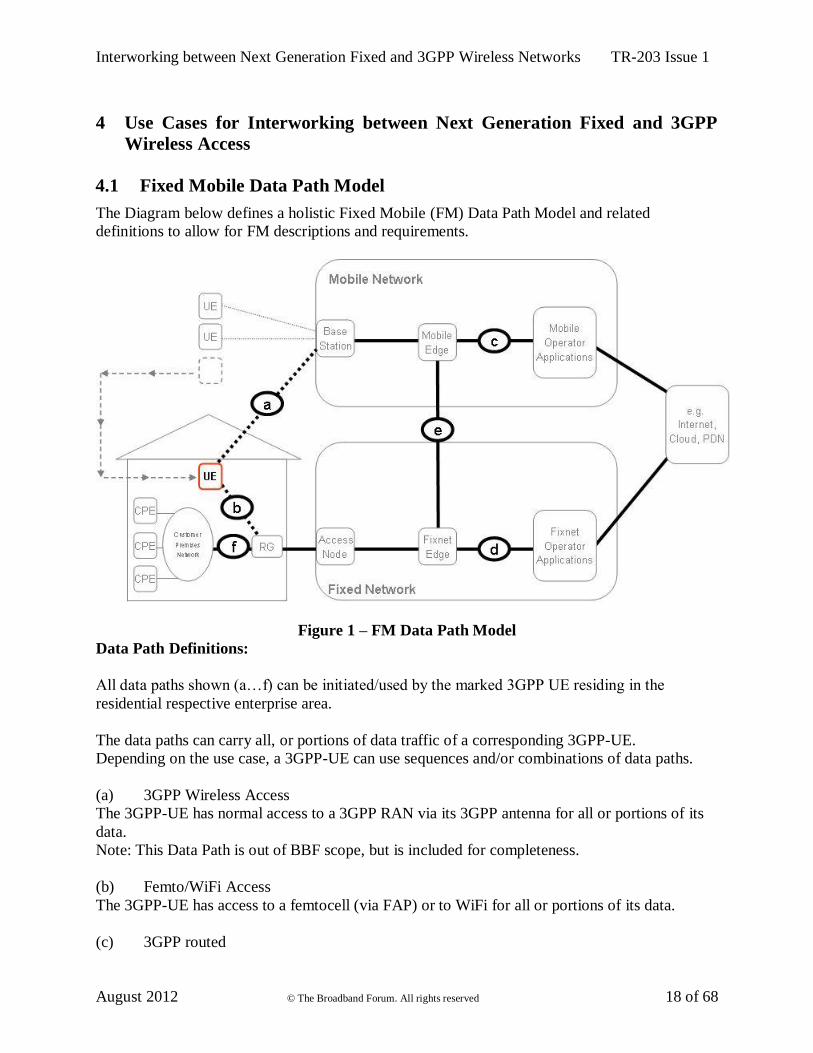
4.1 Fixed Mobile Data Path Model
The Diagram below defines a holistic Fixed Mobile (FM) Data Path Model and related
definitions to allow for FM descriptions and requirements.
Figure 1 – FM Data Path Model
Data Path Definitions:
All data paths shown (a…f) can be initiated/used by the marked 3GPP UE residing in the
residential respective enterprise area.
The data paths can carry all, or portions of data traffic of a corresponding 3GPP-UE.
Depending on the use case, a 3GPP-UE can use sequences and/or combinations of data paths.
(a) 3GPP Wireless Access
The 3GPP-UE has normal access to a 3GPP RAN via its 3GPP antenna for all or portions of its
data.
Note: This Data Path is out of BBF scope, but is included for completeness.
(b) Femto/WiFi Access
The 3GPP-UE has access to a femtocell (via FAP) or to WiFi for all or portions of its data.
(c) 3GPP routed
Interworking between Next Generation Fixed and 3GPP Wireless Networks TR-203 Issue 1
August 2012 © The Broadband Forum. All rights reserved 19 of 68
The 3GPP-UE’s flows (all or portions of) as connected by (a) or (b) are routed to the applications
of the appropriate 3GPP network Operator or attached services (e.g. internet-based services).
Note: This Data Path is out of BBF scope but included for completeness.
(d) BBF routed
The 3GPP-UE’s flows (all or portions of) as connected by (a) or (b) are routed to the applications
of the appropriate BBF network Operator or attached services (e.g. internet-based services).
(e) FM Interface
Two cases can be distinguished:
The 3GPP-UE’s flows (all or portions of) as connected by (b) are routed to the 3GPP network.
The 3GPP-UE’s flows (all or portions of) as connected by (a) are routed to the BBF network.
Datapath (e) assumes a private peering arrangement between fixed and 3GPP networks.
(f) Wired Wireline Local Access
The 3GPP-UE’s flows (all or portions of) as connected by (b) are routed to local devices via the
RG.
4.2 Introduction
The following use cases are for the Interworking between Next Generation Fixed and 3GPP
Wireless Access for 3GPP UE devices only. These use cases include public and enterprise
network fixed access types and a reasonable set of permutations of fixed access types. These
include WiFi provided by Non-3GPP SP’s, fixed access such as Ethernet and H(e)NB for 3GPP
UE devices to move between the different access types and Service Providers. These are
deployed in a variety of fixed served access locations such as broadband Home Networks, public
Hot Spots, community WiFi, Business Intranets and Public Zones.
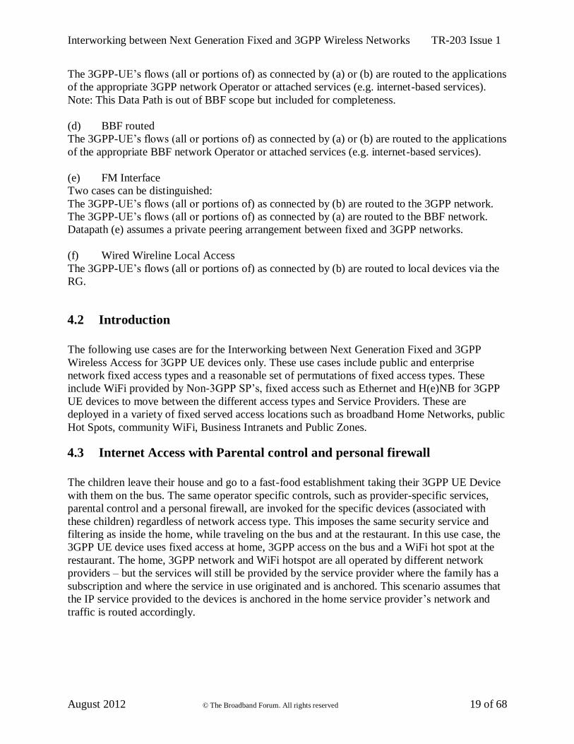
4.3 Internet Access with Parental control and personal firewall
The children leave their house and go to a fast-food establishment taking their 3GPP UE Device
with them on the bus. The same operator specific controls, such as provider-specific services,
parental control and a personal firewall, are invoked for the specific devices (associated with
these children) regardless of network access type. This imposes the same security service and
filtering as inside the home, while traveling on the bus and at the restaurant. In this use case, the
3GPP UE device uses fixed access at home, 3GPP access on the bus and a WiFi hot spot at the
restaurant. The home, 3GPP network and WiFi hotspot are all operated by different network
providers – but the services will still be provided by the service provider where the family has a
subscription and where the service in use originated and is anchored. This scenario assumes that
the IP service provided to the devices is anchored in the home service provider’s network and
traffic is routed accordingly.
Interworking between Next Generation Fixed and 3GPP Wireless Networks TR-203 Issue 1
August 2012 © The Broadband Forum. All rights reserved 20 of 68
Figure 2 – Kids accessing services from the Home Service Provider
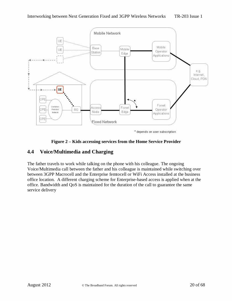
4.4 Voice/Multimedia and Charging
The father travels to work while talking on the phone with his colleague. The ongoing
Voice/Multimedia call between the father and his colleague is maintained while switching over
between 3GPP Macrocell and the Enterprise femtocell or WiFi Access installed at the business
office location. A different charging scheme for Enterprise-based access is applied when at the
office. Bandwidth and QoS is maintained for the duration of the call to guarantee the same
service delivery

Interworking between Next Generation Fixed and 3GPP Wireless Networks TR-203 Issue 1
August 2012 © The Broadband Forum. All rights reserved 21 of 68
Figure 3 – Father travels while call ongoing. Call is originally initiated from 3GPP Wide
Area to Enterprise Network in Office
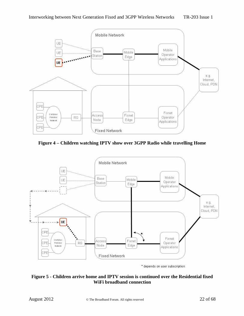
4.5 Video
The children in the backseat of the car are watching an Internet TV show on their laptop using a
3GPP Radio Access Network connection to the Internet TV Provider while travelling home from
the grandparent’s house. Once home, the terminal detects indoor WiFi coverage where the
subscriber has a WiFi Residential Gateway connected to the fixed broadband network. The user
may select to switch the connection or the terminal may automatically select to switch the IP
connection to the fixed broadband connection and enable the user to resume watching the same
TV show on the same laptop, possibly with a better quality picture as allowed by the available
bandwidth, user-specific policy, network policy and QoS setting.
Interworking between Next Generation Fixed and 3GPP Wireless Networks TR-203 Issue 1
August 2012 © The Broadband Forum. All rights reserved 22 of 68
Figure 4 – Children watching IPTV show over 3GPP Radio while travelling Home
Figure 5 - Children arrive home and IPTV session is continued over the Residential fixed
WiFi broadband connection

Interworking between Next Generation Fixed and 3GPP Wireless Networks TR-203 Issue 1
August 2012 © The Broadband Forum. All rights reserved 23 of 68
4.6 3G Femto
A subscriber desires to improve coverage and access speed for their 3G device in their home.
They purchase and install a small Home NodeB (HNB) or Home eNodeB (H(e)NB) (FAP)
device for their home. This device attaches to the home LAN and establishes a connection back
to the subscriber’s mobility service provider network via the fixed broadband network. The
mobility provider cooperates with the broadband access provider to deliver proper bandwidth
and QoS to support a good Quality of Experience (QoE) for calls and data sessions from 3GPP
UEs made within the home for mobility network-based services. The femtocell also allows some
types of data traffic to be shared with the home LAN, including traffic for Internet applications.
Local traffic can be discerned and accounted for differently than traffic that is carried on the
mobile network.
Figure 6 – Subscriber installs a FAP in the Home Network and the fixed SP has an
agreement with the mobility provider for service delivery back to the Mobile network

Interworking between Next Generation Fixed and 3GPP Wireless Networks TR-203 Issue 1
August 2012 © The Broadband Forum. All rights reserved 24 of 68
4.7 Application Mobility
A subscriber desires to use an application on his mobile device, and then wishes to change the
device they are using to a fixed Home Network attached device. Like the use case described in
section 4.4, a multimedia call is handed over from the mobility macro network to a home
network, but instead of remaining on the same device, the father chooses to transfer the
multimedia call to a Media Device connected to a large screen TV display and resumes the call
on that device. Bandwidth and QoS is maintained for the large screen experience to be
meaningful. Accounting and settlement is supported between the application and network service
providers.
Figure 7 - Application Mobility, session moved from 3GPP macro network to fixed
broadband network and different device attached to fixed network only
As an example, mechanisms for providing IMS application mobility between different UEs are
described in 3GPP TS 23.237 [7].

Interworking between Next Generation Fixed and 3GPP Wireless Networks TR-203 Issue 1
August 2012 © The Broadband Forum. All rights reserved 25 of 68
4.8 Dual-WAN connected device
A subscriber has an RG connected through the fixed broadband network. The RG also has an
embedded 3G modem that provides a back-up WAN connection through the 3GPP mobile
network, when the fixed broadband network is unavailable.
The subscriber is using broadband services, such as IP telephony, IPTV and web access. When
the fixed broadband network gets disconnected inadvertently, some of the ongoing
communications are automatically switched to the backup WAN connection and through the
3GPP network: the voice conversation is not disturbed by this event and continues seamlessly;
HD-TV is interrupted as the bandwidth of the mobile network does not support that service;
Internet service is maintained, but with a reduced bandwidth.
Similarly, when the fixed broadband network is re-established, communications ongoing through
the 3GPP network switch are switched back seamlessly to the fixed broadband network, without
perceptible interruption by the end-user.
A sub use case of this scenario is where the 3GPP connectivity is only established upon failure of
the fixed WAN connectivity. In this scenario service is disrupted when the WAN connection
switches from fixed to the 3GPP network, or vice versa.
Note that additional capabilities in the BBF network may be required to support this use case.
Figure 8 – Dual WAN Connected CPE with 3GPP Radio Access as backup connection
Interworking between Next Generation Fixed and 3GPP Wireless Networks TR-203 Issue 1
August 2012 © The Broadband Forum. All rights reserved 26 of 68
5 Interworking Reference Architecture
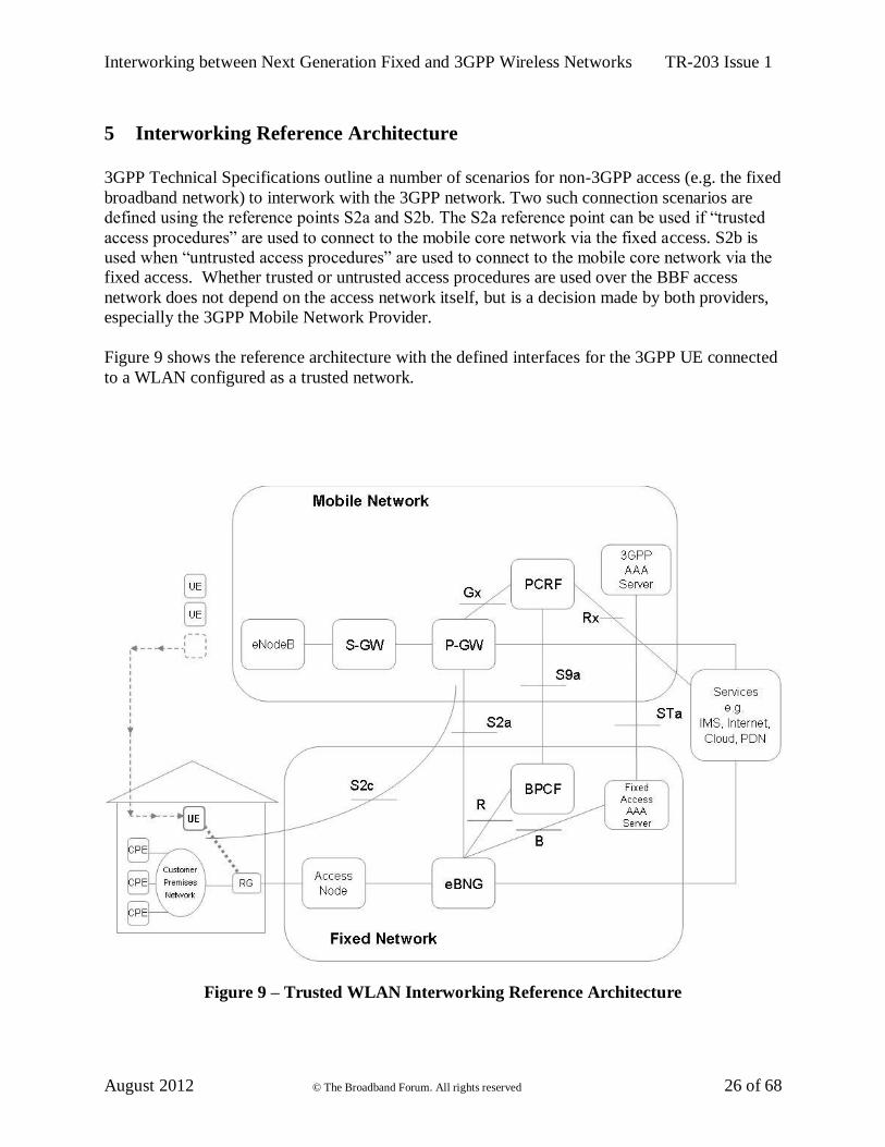
3GPP Technical Specifications outline a number of scenarios for non-3GPP access (e.g. the fixed
broadband network) to interwork with the 3GPP network. Two such connection scenarios are
defined using the reference points S2a and S2b. The S2a reference point can be used if “trusted
access procedures” are used to connect to the mobile core network via the fixed access. S2b is
used when “untrusted access procedures” are used to connect to the mobile core network via the
fixed access. Whether trusted or untrusted access procedures are used over the BBF access
network does not depend on the access network itself, but is a decision made by both providers,
especially the 3GPP Mobile Network Provider.
Figure 9 shows the reference architecture with the defined interfaces for the 3GPP UE connected
to a WLAN configured as a trusted network.
Figure 9 – Trusted WLAN Interworking Reference Architecture

Interworking between Next Generation Fixed and 3GPP Wireless Networks TR-203 Issue 1
August 2012 © The Broadband Forum. All rights reserved 27 of 68
With S2a, the 3GPP PDN Gateway interfaces directly with the eBNG as shown in Figure 9.
When the 3GPP UE connects via the WiFi AP, the fixed network proxies the 3GPP UE
authentication signaling to authenticate with the home 3GPP network using 3GPP-based access
authentication methods.
Figure 10 shows the case of a 3GPP UE connected via WLAN to the BBF network configured
as an untrusted network.
Figure 10 – Untrusted WLAN Interworking Reference Architecture
The 3GPP UE connects to the 3GPP network by means of an IPSec tunnel established between
the 3GPP UE and the ePDG in the 3GPP network, shown here as the SWu reference interface.
SWu supports 3GPP UE-initiated IPSec tunnel establishment, user data packet transmission
within the tunnel and tunnel teardown. The SWn interface is defined between the ePDG and the
eBNG and is only used to carry the IP traffic between the eBNG and ePDG. Note that even
though these procedures are described for “untrusted access”, it is assumed that there is a
business agreement and trust relationship between the BBF access provider and the 3GPP
Evolved Packet Core provider in order to allow, for example, policy interworking.

Interworking between Next Generation Fixed and 3GPP Wireless Networks TR-203 Issue 1
August 2012 © The Broadband Forum. All rights reserved 28 of 68
Figure 11 depicts the reference architecture for the femtocell scenario.
Figure 11 – Femto interworking reference architecture
For all the three possible reference architectures, S9a interface is used for interconnecting Policy
Managers between fixed and wireless service provider domains.
5.1 Interworking Framework
This Section describes the required Interworking functions from the perspective of the BBF fixed
access network. Interworking needs to be looked at from both the user plane and control plane
perspectives. The following diagram illustrates this:

Interworking between Next Generation Fixed and 3GPP Wireless Networks TR-203 Issue 1
August 2012 © The Broadband Forum. All rights reserved 29 of 68
Figure 12 – 3GPP Interworking Reference Architecture
A 3GPP UE attaches to a BBF fixed broadband network and needs to access a service provided
by the Evolved Packet System (EPS). Irrespective of whether WiFi access or femtocell access is
used, two types of Interworking are required: Control Plane Interworking and User Plane
Interworking.
Some user plane traffic to and from the 3GPP UE will be transparent to the BBF network as in
the case of S2c and S2b. This includes:
Traffic related to the service over the S1 or Iuh reference point (e.g. VoIP)
Traffic related to communication between the UE and components inside the EPS over
the S2a, S2b, SWu (IPsec) and S2c reference point (e.g. attachment, mobility signaling)
Where the control planes from both networks need to interconnect, then control plane traffic is
generated. This comprises:
AAA interconnection (STa, SWa) in the case where 3GPP UEs are authenticated in the
BBF network using identities provided by the 3GPP network
Policy interconnection (S9a) in the case where policy requests, responses or events are to
be exchanged. The reference points involved on the BBF side are A, B and R. S9a would
act as an implementation of the BPCF’s I reference point.
Note: local user plane traffic offloading in the BBF network is not shown in the diagram above.

Interworking between Next Generation Fixed and 3GPP Wireless Networks TR-203 Issue 1
August 2012 © The Broadband Forum. All rights reserved 30 of 68
6 Interworking Architecture Requirements
This section describes requirements that must be satisfied by the Next Generation Fixed and
3GPP Wireless Access interworking architecture.
6.1 Common Interworking Architecture Requirements
This section contains the common requirements for the Next Generation Fixed and 3GPP –
Wireless Access Interworking solution.
[R-1] The Interworking solution MUST support 3GPP UE connectivity to a 3GPP Mobile
Network Provider over the broadband network via WiFi, wireline and femtocell.
[R-2] The Interworking solution SHOULD be able to maintain the end-to-end QoS of ongoing
service sessions when a terminal moves between a 3GPP network and a fixed broadband
network.
[R-3] The Interworking solution MUST support at least the following categories of service:
Voice, Video, Text Messaging, Instant messaging, and Data Services.
[R-4] The Interworking solution MUST be capable of uniquely identifying the 3GPP UE
connected to the fixed broadband network that is authenticated by the Home 3GPP
network.
[R-5] The Interworking solution MUST provide security so that a breach in one access network
would not compromise the security of other access types or networks.
[R-6] The Interworking solution SHOULD provide reasonable protection against threats and
attacks present in the Internet.
[R-7] The Interworking solution MUST support EAP-AKA/SIM authentication and the
transport of encrypted traffic for the 3GPP UE
[R-8] The Interworking solution SHOULD NOT interfere with service delivery or inter-access
handovers in a way that is noticeable to end-users or service providers.
[R-9] The Interworking solution MUST NOT prevent Lawful Intercept in the presence of
offloading 3GPP UE traffic through the fixed broadband network.
[R-10] The Interworking solution MUST ensure that no unauthorized user can obtain a
legitimate IP address.
[R-11] The Interworking solution MUST provide a mechanism to support QoS agreements
between the 3GPP Mobile Network Provider and the fixed broadband network provider.
Interworking between Next Generation Fixed and 3GPP Wireless Networks TR-203 Issue 1
August 2012 © The Broadband Forum. All rights reserved 31 of 68
[R-12] The Interworking solution MUST provide a mechanism to hide network topologies
between a 3GPP and a BBF network operator.
[R-13] When a 3GPP UE device is attached to a BBF network, the Interworking solution MUST
support access to fixed services and the Internet through the BBF network.
[R-14] The Interworking solution MUST support connectivity for routing parts of the traffic
through the BBF network and the remainder back to the 3GPP network.
[R-15] The Interworking solution MUST allow the BBF network to respond to resource requests
from the 3GPP Network Provider.
[R-16] The Interworking solution MUST support IP network mobility and roaming between
3GPP wireless accesses and fixed WiFi broadband accesses.
[R-17] The Interworking solution MUST ensure that responses to requests for dynamic resource
management from the 3GPP network provider are sent within the limits acceptable to the
3GPP network provider.
[R-18] The Interworking solution MUST be able to authenticate the 3GPP UE device attaching
to WiFi using 3GPP access authentication methods.
[R-19] The Interworking solution MUST support transport of encrypted traffic for the 3GPP UE
and mobile provider EPC Core network.
[R-20] The eBNG MUST support the S2a interface for trusted access.
Note: detailed requirements will follow in WT-291 [17].
6.2 Requirements for Authentication of a 3GPP UE connected to WLAN
This section provides a set of requirements for authenticating a 3GPP UE in the fixed broadband
access network connected via a WLAN and provides examples of applications that can be
enabled by such authentication. A solution for authenticating 3GPP UEs is described in WT-146
[16].
Two Authentication models exist when a 3GPP UE is connected to a non-3GPP Access network
and is authenticated by the devices Home 3GPP Network. These two models differ as to whether
the Non-3GPP Access Network is considered Trusted or Untrusted by the Home 3GPP Network.
The Non-3GPP network may be considered trusted or untrusted, partly based on support of
secure features, but also based on the relationship between the operators, and any other elements
considered relevant. For example the same BBF network might be considered trusted by mobile
operator A, but untrusted by mobile operator B.
Authentication Model #1 Trusted Non-3GPP Access Network Provider: The Non-
3GPP Access Network such as the Next Generation Fixed Broadband Network is

Interworking between Next Generation Fixed and 3GPP Wireless Networks TR-203 Issue 1
August 2012 © The Broadband Forum. All rights reserved 32 of 68
considered Trusted by the Home 3GPP Network provider when it fulfills all the
security features deemed necessary by the Home 3GPP Network provider. The
Home 3GPP Network Provider owns the 3GPP device subscription. This is also
the case where the fixed and 3GPP wireless network providers have a business
agreement to permit the 3GPP UE to access the fixed broadband network services
like Internet and localized services where the fixed and wireless access network
share the EPS network.
Authentication Model #2 Untrusted Non-3GPP Access Network Provider: The
Non-3GPP Access Network is considered Untrusted by Home 3GPP network
when it does not fulfill the security features required by the Home 3GPP Network
Provider. In this case, the fixed and 3GPP wireless network providers do not have
a business agreement in place.
6.2.1 Authentication Model #1: Authentication in a trusted fixed broadband
access network
Access authentication is used for Access Control in the fixed broadband network, to permit or
deny the 3GPP UE access, and the use of resources. The Authentication signaling is proxied by
the fixed broadband network and sent back to the Home 3GPP AAA/HSS server for
authentication.
[R-21] The Interworking Solution MUST support the proxying of EAP-AKA/SIM authentication
to the Home 3GPP Service Provider Network.
6.2.2 Authentication Model #2: Authentication in an untrusted fixed
broadband access network
In an Untrusted Access Network, the 3GPP UE is authenticated to the Home 3GPP network
where the authentication signaling is tunneled over the fixed broadband access network and is
not visible to the fixed broadband Service Provider. This authentication type is referred to as
Tunnel Authentication whereby the 3GPP UE establishes an IPSec Tunnel to the evolved
Packet Data Gateway (ePDG) and performs mutual authentication during the IPSec Tunnel
establishment to the ePDG. The ePDG is a node in the Home 3GPP Network.
6.3 Requirements for Policy Control and Accounting
[R-22] The Interworking solution MUST be able to work within a policy framework. Note: such
policy framework is described in section 8.1.
[R-23] The Interworking solution MUST support the interconnection of policy and accounting
systems between the 3GPP and fixed broadband network for offloading in the case of
WiFi and femto Access.
Interworking between Next Generation Fixed and 3GPP Wireless Networks TR-203 Issue 1
August 2012 © The Broadband Forum. All rights reserved 33 of 68
[R-24] The Interworking Solution MUST support the secure exchange of policy information
with the 3GPP provider.
[R-25] The Interworking solution MUST support accounting models for WLAN access and
femto access.
[R-26] The BPCF in fixed broadband network MUST support the S9a interface.
[R-27] The Interworking solution MUST support the exchange of accounting information
between the fixed and 3GPP networks for the purpose of billing.
[R-28] In the case of S2a, the Interworking solution SHOULD support multiple QoS class
allocation inside the same IP tunnel by mapping the inner IP QoS marking to the outer IP
header at the tunnel ingress.
6.4 Requirements for WiFi Access
[R-29] The Interworking Solution SHOULD support the identification of IP flows from a 3GPP
UE behind a Residential Gateway (RG) /WLAN Access Points (AP).
6.4.1 IP addressing requirements
[R-30] The 3GPP UE MUST be able to obtain locally, one or more IPv4 addresses and/or IPv6
addresses/IPv6 Prefixes.
[R-31] The Interworking solution MUST ensure that the 3GPP UE, using any of the
aforementioned addresses, can reach its 3GPP home network.
[R-32] The Interworking solution MUST support IP Address allocation methods as required by
the 3GPP UE device.
6.4.2 Access control requirements
[R-33] The Interworking Solution MUST support access control on 3GPP UEs that are
attempting to connect via WiFi, based on the subscriber’s SIM/USIM card or a local
authentication method such as a WPA or HotSpot 2.0.
6.4.3 Quality of Service requirements
The following requirements are applicable to WiFi access when the Interworking agreement
includes support for QoS.
Interworking between Next Generation Fixed and 3GPP Wireless Networks TR-203 Issue 1
August 2012 © The Broadband Forum. All rights reserved 34 of 68
[R-34] The Interworking solution MUST provide mechanisms to support QoS functionality
between the 3GPP network provider and the fixed broadband network provider.
[R-35] The Interworking solution MUST support maintaining end-to-end QoS when the 3GPP
UE moves from 3GPP network to WiFi Access attached to the fixed broadband network,
and the fixed access network supports the required QoS.
[R-36] The Interworking Solution MUST support being able to change QoS, when the 3GPP UE
moves from 3GPP network to the WiFi Access attached to the fixed broadband, and fixed
access network does not provide the same QoS as the macro network.
6.4.4 Session Continuity for WiFi Access
The following are applicable for scenarios where there is an Interworking agreement between the
3GPP network provider and the fixed broadband network provider which supports IP session
continuity.
[R-37] The Interworking solution MUST provide mechanisms to support IP session continuity
(IP address preservation) when WiFi access is used as agreed between the 3GPP mobile
network provider and the fixed broadband network provider.
[R-38] In the case of the S2a interface, the Interworking solution MUST be able to maintain the
same IP address for handovers from 3GPP Macro to WLAN and vice versa.
6.4.5 WLAN Offload Requirements
This section describes the scenarios where part or all of the traffic from a UE WLAN interface is
BBF-routed (i.e. routed from the RG through the BNG without traversing the 3GPP network. See
Figure 1, path (b) – (d)). These scenarios assume that the mobile service provider entrusts the
fixed mobile provider for the policy control of the offloaded traffic. Moreover, session
continuity can no longer be rendered by the 3GPP provider since the data path is no longer
3GPP-routed (i.e. no longer traverses 3GPP core network).
6.4.5.1 General requirements
[R-39] The Interworking Solution MUST be able to support policy enforcement for the WLAN
offload traffic.
6.4.5.2 Requirements specific to Partial WLAN Offload
[R-40] The Interworking solution MUST support selected flows of a UE’s traffic going through
WiFi being 3GPP-routed whereas the remaining parts are BBF-routed.

Interworking between Next Generation Fixed and 3GPP Wireless Networks TR-203 Issue 1
August 2012 © The Broadband Forum. All rights reserved 35 of 68
[R-41] The Interworking solution MUST support QoS and accounting for both types of traffic
defined in [R-40].
6.5 Requirements for femtocells
6.5.1 3GPP femtocell connecting to Broadband access network
The 3GPP specifications support 3GPP femtocells (H(e)NB) connected over a Next Generation
fixed broadband network by establishing a secure connection from the femtocell using IPSec to
the Security Gateway (SeGW) located in the 3GPP network. The HeNb authenticates to the
SeGW via mutual authentication. The mutual authentication is part of the IKEv2 tunnel
establishment procedure and it is based on device certificates and USIM credentials installed in
the H(e)NB. This authentication process is invisible to the Broadband access network, since it
does not involve any Broadband access network elements. From the femtocell’s point of view
the precondition is the assignment of an IP address from the BBF network (i.e. the interface
between the femtocell and the RG) and the 3GPP UE devices connected to this femtocell
obtaining an IP address from the EPC network.
When a 3GPP UE is connecting to the H(e)NB, the authentication and any signaling between the
3GPP UE and the 3GPP network is transparent to the broadband access network, since this
traffic is passing within the IPSec tunnel from the HeNB to the SeGW.
6.5.2 Admission Control Requirements
[R-42] It MUST be possible to perform flow admission control on the femtocell where there is
statically provisioned bandwidth in the backhaul provided by the fixed broadband
provider.
[R-43] It MUST be possible to perform flow admission control on the femtocell within the
backhaul bandwidth that is set when the femtocell establishes connectivity with the 3GPP
provider network. This bandwidth allocation for the aggregated IPSec tunnel is not
performed on a per-call basis.
[R-44] It MUST be possible to perform flow admission control on the femtocell that is
coordinated with flow admission control on the backhaul, where the fixed broadband
provider supports admission control.
6.5.3 Quality of service Requirements
[R-45] The Interworking solution MUST support maintaining end-to-end QoS when the 3GPP
UE moves from 3GPP network to FAP attached to the fixed broadband network, and the
fixed access network supports the required QoS.
Interworking between Next Generation Fixed and 3GPP Wireless Networks TR-203 Issue 1
August 2012 © The Broadband Forum. All rights reserved 36 of 68
6.5.4 LIPA (Local IP Access) to the customer premises network
[R-46] The interworking solution MUST enable support for Local IP Access to the customer
premises network without traffic leaving that network, in order to provide access for a
directly connected 3GPP UE (i.e. using femtocell radio access) to other IP capable
devices in the home.
[R-47] The Interworking Solution MUST support simultaneous access from a 3GPP UE to both
the 3GPP provider’s core network, and to the customer premises network.
6.5.5 SIPTO (Selected IP Traffic Offload) for femtocell
[R-48] The Interworking solution MUST support Selected IP Traffic Offload i.e. from the 3GPP
provider network.
[R-49] The Interworking Solution MUST be able to support only the IP traffic from a given
3GPP UE associated with a particular IP network being offloaded.
[R-50] The Interworking Solution MUST support offloading selected IP traffic for a 3GPP UE
without adversely affecting other IP traffic on the same 3GPP UE.
6.6 Requirements for Simultaneous Wireless Multi-Access
A (dual radio) UE can be attached to:
one 3GPP access,
one WiFi access
one 3GPP access and WiFi access simultaneously.
Simultaneous Multi-Access is the case where the 3GPP UE has two IP connections established at
the same time, one over the 3GPP Access Network (path (a)-(c)) and another connection to the
fixed broadband network via WiFi (path (b)-(e)-(c)). This encompasses the MAPCON scenarios
(cf. 3GPP TR 23.861) and the IFOM scenarios (cf. 3GPP TS 23.261).
[R-51] The Interworking Solution MUST be able to support two simultaneous IP connections,
one via 3GPP access and the other via WiFi access
[R-52] The Interworking Solution MUST be able to provide network selection policies to allow
the UE to select the appropriate IP connection.

Interworking between Next Generation Fixed and 3GPP Wireless Networks TR-203 Issue 1
August 2012 © The Broadband Forum. All rights reserved 37 of 68
7 AAA Interworking Architecture
This section describes the AAA Control Plane interaction between the fixed broadband network
and 3GPP Mobile Network Providers over the STa/SWa reference points to support
authentication of a 3GPP UE device in a fixed broadband network, and the generation of
accounting data for 3GPP UE devices.
7.1 AAA Interworking
Trusted Interworking requires 3GPP UE authentication by proxying in the BBF network using an
interconnection of the fixed-line AAA server with the mobile network’s AAA server. In the
untrusted Interworking scenario this is optional. The AAA servers in each Network Provider’s
domain have a trust relationship established and, when a 3GPP UE attaches to the BBF network,
it is authenticated by its home 3GPP network through the BBF network.
[R-53] The Interworking Solution MUST support the identification of the home 3GPP provider
for a given 3GPP UE when it provides service to that 3GPP UE on behalf of that 3GPP
provider.
[R-54] The Interworking solution MUST support proxying authentication signaling between the
3GPP UE and its home 3GPP network.
[R-55] The Interworking solution MUST support the ability to distinguish between different
traffic flows based on the IP header information for the purposes of AAA.
[R-56] The Interworking solution MUST support accounting for a 3GPP UE based upon QoS or
bandwidth resources for a specific traffic flow.
[R-57] The Interworking solution MUST support a 3GPP UE gaining authorized access to
services owned by the 3GPP provider, even when those services are provided by a
different service provider.
[R-58] The Interworking solution MUST provide the access network provider identification of
the BBF network in the authentication request proxied to the 3GPP AAA server.
[R-59] The Interworking Solution MUST support the communication of IMSI (3GPP TS 23.003
[4]) associated with the 3GPP UE from the 3GPP AAA to the fixed AAA in order to
identify the 3GPP UE.

Interworking between Next Generation Fixed and 3GPP Wireless Networks TR-203 Issue 1
August 2012 © The Broadband Forum. All rights reserved 38 of 68
7.2 Description and Functionality of reference points STa and SWa
The STa reference point is defined between the Trusted non-3GPP IP access network and the
3GPP AAA Server or Proxy. The STa reference point transports the authentication messages
towards the 3GPP AAA. The STa reference point transports access authentication, authorization,
mobility parameters and charging-related information such as RADIUS accounting session data
in a secure manner.
The SWa reference point is defined between the Untrusted non-3GPP IP access and the 3GPP
AAA server or Proxy. The SWa reference point transports authentication and authorization
information in a secure manner and can also be used to authenticate and authorise the 3GPP UE
in the untrusted scenario (such as those devices connected via S2b interface). The 3GPP UE and
the ePDG perform mutual authentication during the IPSec tunnel establishment between the
3GPP UE and the ePDG. This mutual authentication is transparent to the fixed access network.
Before the IPSec tunnel establishment between the 3GPP UE and the ePDG is performed, the
3GPP UE needs to obtain IP connectivity across the fixed access network, which requires an
access authentication within the fixed broadband network (see the authentication methods
described in WT-146 [16]).
[R-60] The interworking solution MUST support proxying the authentication signaling to the
3GPP AAA Server or Proxy over the STa reference point.
[R-61] The interworking solution MUST support proxying the authentication signaling to the
3GPP AAA Server over the SWa reference point.
7.2.1 Translation Agent for Interworking between BBF and Mobile Network
Providers
Most fixed broadband networks have AAA Servers that are based on RADIUS whereas the
3GPP Providers’ AAA servers use Diameter. Therefore, in order for the fixed broadband
network to support the STa and SWa for authentication signaling, authorization and accounting
data, an Interworking function is required to translate between the RADIUS protocol and
Diameter protocol. This is achieved with the use of a Translation Agent (TA) as shown in Figure
13.
[R-62] The Interworking solution MUST support a Translation Agent residing in the BBF
network to facilitate authentication signalling initiated in the BBF network over the STa
or SWa reference points

Interworking between Next Generation Fixed and 3GPP Wireless Networks TR-203 Issue 1
August 2012 © The Broadband Forum. All rights reserved 39 of 68
Figure 13 – Translation Agent for Interworking between RADIUS and DIAMETER
protocols between the BBF AAA and 3GPP AAA domains
7.3 Accounting Interworking
Three deployment models are considered for exchanging accounting information between the
fixed and mobile network Service Providers, these are:
The Service Providers have agreements with each other for accounting.
A fixed Service Provider routes traffic back to the Home 3GPP Network, which in this
case is the 3GPP Network SP, when required to do so.
Fixed Service Provider offers Wholesale Service to the Mobile Network.
When a 3GPP UE roams from the Mobile Network into the fixed broadband network, traffic
from the mobile device is routed back to its Home Network, i.e. the 3GPP Mobile Network. In
other cases, traffic is offloaded and routed by the fixed network SP. In order for the fixed SP to
“charge” the mobile network SP for this Home routed traffic, accounting of the traffic is required
for this 3GPP UE for Home routed traffic.
The accounting records at the BNG would typically be generated based on Volume Based
Accounting for 3GPP Home Routed Traffic when the 3GPP UE device is connected to the fixed
broadband connection via the fixed subscribers Home RG. In other scenarios, such as WiFi hot
spots, accounting may be performed by other network nodes. The fixed SP may require a more
granular accounting scheme in order to provide a “Tiered charging model” for the 3GPP SP
based on the “class of service” of traffic – for example, the QoS of traffic based on the DSCP
markings in IP packets sent/received from the 3GPP UE.
Note that the fixed broadband network AAA may be segregated into several AAAs for different
access or network segments, for example one AAA performing accounting for data carried of
WiFi hotspots and a separate AAA accounting for data carried over the mobile backhaul to the
3GPP Mobile Network.
7.3.1 Accounting Interworking Scenarios
In today’s fixed networks, accounting is typically performed using RADIUS Accounting at the
BNG based on Time or Volume Based Accounting for fixed subscribers connected via the RG.
For the Interworking solution, the RADIUS Accounting may be performed by nodes such as the
RG and/or BNG would do RADIUS Accounting for traffic to/from the 3GPP Mobile device

Interworking between Next Generation Fixed and 3GPP Wireless Networks TR-203 Issue 1
August 2012 © The Broadband Forum. All rights reserved 40 of 68
under the deployment scenarios noted below, and send this accounting session data to the fixed
Broadband AAA Server.
In order for the fixed broadband network Provider to charge the Mobile Network Provider for
traffic originating from the 3GPP UE, the fixed broadband network performs RADIUS
Accounting Session for traffic that is routed back to the 3GPP UEs Home Mobile Network, i.e.
Home Routed Traffic, and possibly another RADIUS Accounting Session for traffic routed out
locally to the Internet for example.

Interworking between Next Generation Fixed and 3GPP Wireless Networks TR-203 Issue 1
August 2012 © The Broadband Forum. All rights reserved 41 of 68
7.3.1.1 Single RADIUS Accounting for home and local routed traffic
In Figure 14, where the fixed SP and mobile SP are a single SP, the fixed SP performs a “single
RADIUS Accounting Session for both traffic routed back to the Home Mobile Network and
traffic routed out locally via the BNG”. The accounting information is then sent to the 3GPP
Network Provider’s AAA so that it may perform the necessary charging/billing of data for this
3GPP UE.
Note: In the HeNB case there are scenarios whereby all traffic is not routed via the BNG. This is
applicable to all 4 accounting scenarios.
Figure 14 – Single RADIUS Accounting session for Home Routed and WiFi Offloaded
traffic at the BNG

Interworking between Next Generation Fixed and 3GPP Wireless Networks TR-203 Issue 1
August 2012 © The Broadband Forum. All rights reserved 42 of 68
7.3.1.2 Two RADIUS Accounting sessions for home and local routed traffic
In Figure 15 the fixed network SP has a business agreement with the mobile network SP and
does two RADIUS Accounting Sessions, one for Home Routed traffic to the mobile network and
the other for traffic routed locally to the Internet or external service via the BNG.
Figure 15 – Two RADIUS Accounting Sessions, one for Home Routed traffic and another
for traffic routed out to the Internet at the BNG
7.3.1.3 Single RADIUS Accounting for home routed traffic
In Figure 16 the fixed network SP has a business agreement with the mobile network SP as in
figure 12. However the fixed SP does not account for traffic sent out locally to the Internet. This
is because the 3GPP UE is connected to its fixed WiFi Home Network and the fixed SP does not
account for traffic routed out locally for this 3GPP mobile device any differently than for any
other traffic coming from its Home Network connection. Therefore in this scenario the fixed SP
only sends the mobile network SP one RADIUS Accounting session for the 3GPP Home Routed

Interworking between Next Generation Fixed and 3GPP Wireless Networks TR-203 Issue 1
August 2012 © The Broadband Forum. All rights reserved 43 of 68
Traffic. Traffic that is routed locally at the BNG is part of the fixed line RADIUS Accounting for
the user’s High Speed Internet (fixed line) Subscription.
Figure 16 – RADIUS Accounting Sessions for Home Routed traffic to the Mobile Network
7.3.1.4 RADIUS Accounting for wholesale model
In Figure 17 the fixed SP is providing Wholesale Service for the mobile network SP. In this
scenario one accounting session is generated for traffic that is routed back to the mobile network
SP and one may be generated for traffic routed out locally via the BNG. These two accounting
Sessions are sent back to the mobile network SP to perform the necessary charging/billing for
this 3GPP mobile subscriber, or in the case where the 3GPP UE connects to its WiFi Access
Point in the Home, only traffic that is routed back to the mobile network SP is accounted for on a
per 3GPP UE basis and traffic routed out locally via the BNG is accounted for as part of its fixed
line access subscription.

Interworking between Next Generation Fixed and 3GPP Wireless Networks TR-203 Issue 1
August 2012 © The Broadband Forum. All rights reserved 44 of 68
Figure 17 – Fixed Service Provider offering Wholesale access
In all of these scenarios, the fixed SP may wish to charge not just based on volume, but also on
class of service, for example based on DSCP or destination IP Address. This provides a more
granular type of accounting from which a more tiered and flexible charging/Pricing models can
be built by the fixed and 3GPP network Service Providers.
[R-63] The Interworking solution SHOULD be able to support generating distinct accounting
information for traffic Home routed back to the mobile network, and traffic routed locally
by the fixed broadband network.

Interworking between Next Generation Fixed and 3GPP Wireless Networks TR-203 Issue 1
August 2012 © The Broadband Forum. All rights reserved 45 of 68
8 Interworking Policy Control
8.1 Policy Control Network Logical Function
The set of Network Logical Functions that require information flows for processing policy
decisions and enforcement can be drawn from the Broadband Domain Elements and Interfaces
shown in Figure 18.
Figure 18 – Broadband Domain Elements and Interfaces
Figure 18 depicts the interfaces with a 3GPP wireless domain that would serve as input sources
to BBF wireline domain functions for the wireless-fixed Interworking case:
The interface between the Broadband Policy Control Function (BPCF) and the 3GPP
Policy and Charging Rules Function (PCRF). The current interface between PCRF
functions in 3GPP is S9. The enhanced version of this interface, which 3GPP has
designated S9a, is intended to support Interworking between BBF and 3GPP networks.
The interface between the 3GPP AAA server and the BBF domain AAA counterpart is
either the SWa or the STa interface, depending on the type of incoming call/session
(3GPP TS 23.139 [5]).
Aggregation
ETHETHCPE
User1
User1
Customer PremAccess & Aggregation
Access Node
DSLAMBRAS/BNG
Regional BB Network
TUVA10
MDF
L2TS
IP
PEP
R
A
G
L
PEP
M/Q
RepositoryRepositoryRepository
B
C
D
PEPNodal viewof TR-101TransportNetwork
Functionalview of Control Layer
PDP
Functional view of Application Layer
Security Proxy/Gateway
E
3GPP/AAASWa/STa
(PCRF)
(BPCF)
S9a

Interworking between Next Generation Fixed and 3GPP Wireless Networks TR-203 Issue 1
August 2012 © The Broadband Forum. All rights reserved 46 of 68
The policy decisions are taken in the 3GPP wireless domain and pertinent information needs to
be transported via appropriate interfaces to the logical functions in the BBF domain. The
following assumptions are made.
Policy information will be derived from an Application Function (AF) in the 3GPP
wireless domain. The pertinent information from the 3GPP AF will be submitted by the
3GPP PCRF to the BPCF via the S9a interface.
All parameters/attributes transported by the 3GPP PCRF to the BPCF via S9a are as
defined by 3GPP protocols.
For authorization and authentication of a 3GPP user on a BBF access network, the 3GPP
AAA infrastructure and BBF AAA infrastructure will exchange parameters using the STa
or SWa interface as appropriate.
As noted above, all architectural implementations for all defined Broadband Forum use cases
will require a unique set of information exchanges.
The set of information exchanges with the appropriate [Logical Function, Source] combinations
(cf. TR-134), is as follows.
a. [Logical Function => AAA, Information Source => SWa/STa Interface] – This provides
the authorization and authentication information from the 3GPP domain to the BBF AAA
proxy via the SWa or STa interfaces as the case may be.
b. [[Logical Function => BPCF, Information Source => S9a Interface] – This is the
exchange of information over the S9a interface whereby parameters/attributes are sent
from the 3GPP PCRF to the BPCF over the S9a interface
c. [Logical Function => S9a Interface (to remote PCRF in 3GPP domain), Information
Source => PDP/BPCF] – This flow of information from the PDP/BPCF towards the
3GPP PCRF initiates the establishment of an S9a session.
d. [Logical Function => PDP/BPCF; Information Source => AAA] – The AAA
information is conveyed by the BBF AAA proxy to the PDP/BPCF.
e. [Logical Function => PEP; Information Source => PDP/BPCF] – The PDP/BPCF
processes all information flows conveyed to it and then conveys the required information
to the PEP.
f. [Logical Function => PDP/BPCF; Information Source => PEP] – The PEP responds
back to the PDP/BPCF with policy enforcement status information.
g. [Logical Function => S9a Interface (to remote PCRF in 3GPP domain); Information
Source => PDP/BPCF] – The PDP/BPCF responds back to the 3GPP PCRF via the S9a
interface with information on acceptance or rejection of the incoming call/session.

Interworking between Next Generation Fixed and 3GPP Wireless Networks TR-203 Issue 1
August 2012 © The Broadband Forum. All rights reserved 47 of 68
8.2 Interworking options
A fixed broadband access network may contain a BPCF as defined in TR-134 [14], WT-145
[15], and WT-146 [16]. To provide Interworking of Policy Control between BBF and 3GPP
architectures, there is a need to provide interworking between the PCRF and the BPCF in the
fixed broadband network. This Interworking between the BPCF and PCRF relies on the S9a
interface.
In a typical TR-101 [13] defined fixed broadband access network that supports QoS and
attachment control, the interaction between policy controllers can be used to authorize access
attachment as well as authorize use of an established set of QoS capabilities. No call-by-call
bandwidth reservations or other dynamic policies are supported in this simple model. However,
devices can roam into such a wireline network, and can be offered session-independent per-hop
QoS behaviors that provide the required Quality of Experience (QoE) for end users.
In an enhanced wireline access network, more dynamic behaviors are possible, including
providing policy capabilities that allow QoS, bandwidth, and access control for various
application sessions that a roaming device may establish.
Hybrid approaches are also possible. Consider a FAP that relies on a wireline access network to
provide connectivity to other networks, including the home mobile network. The femtocell
provides connectivity to various 3GPP UEs that may be used to access services from one or more
service providers. The FAP may establish basic network access that allows it to send traffic
through the wireline access using available QoS markings within a given overall policy. Such a
policy is not session specific in the traditional sense, but could be described as an access session
for a FAP – something that current wireless policy does not typically manage. Once access is
established for a femtocell, it may provide dynamic sessions to 3GPP UEs through the usual
interactions with the mobile provider core network.
8.3 Requirements for policy control
8.3.1 S9a Session establishment for a 3GPP UE accessing the fixed network
via WLAN
When a 3GPP UE connects to a fixed broadband network via WLAN, the device first attempts to
perform an authentication procedure. Authentication may be performed in one of two ways:
3GPP access authentication or tunnel authentication. 3GPP access authentication results in S9a
session establishment initiated from the BPCF. For the case where 3GPP access authentication
is not performed (i.e. tunnel authentication is performed), the PCRF sends information and
triggers the BPCF to initiate S9a session establishment.
[R-64] The BPCF MUST indicate to the PCRF that the 3GPP UE is making use of the fixed
broadband access.
Interworking between Next Generation Fixed and 3GPP Wireless Networks TR-203 Issue 1
August 2012 © The Broadband Forum. All rights reserved 48 of 68
8.3.1.1 BPCF triggered S9a Session establishment
As part of the Interworking between the fixed and wireless 3GPP networks, the BPCF and PCRF
establish a connection via S9a which is based on Diameter. The BPCF, acting as a client,
initiates the S9a session towards the PCRF which acts as a server. When the BPCF initiates S9a
session it includes the IMSI of the 3GPP UE (if available), IP address assigned to the 3GPP UE,
the APN indication (if available). In addition, the PCRF may request the BPCF to initiate the S9a
session as described in next Section.
When the S9a session is established between the BPCF and PCRF, a unique client generated
“session-id” is created to identify the particular session associated with the 3GPP UE. These
sessions however run over the same S9a connection between two Diameter peer nodes given that
further S9a sessions per 3GPP UE are between the same network domains, i.e. same realms
between the Diameter nodes.
[R-65] The BPCF MUST be able to initiate an S9a session after successful access authentication
of a 3GPP UE connected via WiFi in the fixed broadband network.
[R-66] The BPCF MUST be able to include in the request to PCRF the IMSI of the 3GPP UE (if
available), the IP address assigned to the 3GPP UE, the APN indication (if available).
8.3.1.2 PCRF-triggered S9a Session establishment
The PCRF can trigger the BPCF to initiate S9a session establishment if it becomes aware (e.g.
via tunnel authentication to the 3GPP network) that a 3GPP UE has attached via the BBF access
to WLAN or when the UE perform an attachment to the H(e)NB, and the PCRF is able to find a
corresponding BPCF. The BPCF should be capable of receiving the trigger information from the
PCRF, which may include the IMSI, APN, in case of UE connected to the WLAN, the local UE
IP address assigned to the 3GPP UE or the IP address locally assigned to the H(e)NB by the
fixed broadband network (and the UDP port numbers when there is a NAT). In this way, the
BPCF can initiate S9a session establishment and associate the aggregate IP traffic plane (tunnel)
used by a 3GPP UE with the S9a session towards the PCRF.
[R-67] The BPCF MUST be able to initiate S9a session establishment with the 3GPP PCRF as a
result of a trigger received from the PCRF.
[R-68] The BPCF MUST be able to receive the IMSI of the 3GPP UE, the IP address assigned to
the 3GPP UE, the IP address assigned to the H(e)NB, and the UDP port number when
there is a NAT.

Interworking between Next Generation Fixed and 3GPP Wireless Networks TR-203 Issue 1
August 2012 © The Broadband Forum. All rights reserved 49 of 68
8.3.2 PCRF Discovery
A 3GPP Core network may include more than one PCRF and 3GPP allows different network
node configurations. For example, it is possible to define a specific PCRF and PDN connection,
or a specific PCRF serving a specific 3GPP UE for any kind of PDN connection. The 3GPP
PCRF is the anchor point for all S9a, Gx, and Gxx sessions related to the same 3GPP IP-CAN
sessions. This allows the PCRF to enforce the suitable QoS for the service flow connections
related to the same IP-CAN session when the 3GPP UE is simultaneously connected to different
access networks. The selection of PCRF can be based on the IMSI and in the APN if available.
The 3GPP UE home network may be known to the BPCF, if the 3GPP UE has performed EAP-
based authentication when the 3GPP UE connected to the Broadband access network, as the
home network is derived from the IMSI and the IMSI is included in the realm part of the NAI.
Alternatively, the 3GPP UE IMSI is sent by the PCRF during S9a session establishment. The
home network can be derived from IMSI as defined in 3GPP TR 23.003 [4].
The 3GPP APN is sent by the 3GPP UE to the 3GPP EPC network when the 3GPP UE starts a
new PDN connection. However in s2b and s2c scenarios this information is sent directly to the
3GPP EPC network and it is not visible to the BBF network. In this case, the APN is sent by the
PCRF to the BPCF when triggering the S9a session establishment to the BPCF.
Note: It is for further study how the APN information is sent from the 3GPP UE to the 3GPP
EPC via the Broadband Access network in the s2a scenario. This will be clarified in WT-291.
In order to ensure that in 3GPP networks all sessions for Gx, S9, Gxa/Gxc and Rx for a given
3GPP IP-CAN session reach the same PCRF when multiple and separately addressable PCRFs
have been deployed in 3GPP Network Provider, a "DIAMETER Routing Agent (DRA)"
function may be used. This mechanism is not required in networks that utilize a single PCRF per
DIAMETER realm. The DRA function located in the 3GPP network is contacted by the BPCF to
initiate the s9a session only if more than one PCRF is deployed in the 3GPP Provider’s Network.
The interaction between the DRA and the PCRF is outside the scope of the BBF. However the
BPCF must be able to interact with the PCRF or with the DRA, if deployed in 3GPP EPC
network, for establishing the S9a session.
For Policy sessions initiated from the BPCF to PCRF the following requirements are applicable:
[R-69] The BPCF MUST support the discovery of the 3GPP PCRF based on the IMSI and APN
when available.
[R-70] The BPCF MUST support preconfiguration of knowledge needed to identify the
appropriate PCRF.
[R-71] The BPCF MUST support the discovery of a 3GPP PCRF using a Diameter Routing
Agent function located in the 3GPP mobile network.

Interworking between Next Generation Fixed and 3GPP Wireless Networks TR-203 Issue 1
August 2012 © The Broadband Forum. All rights reserved 50 of 68
[R-72] The BPCF MUST send the 3GPP user identity (3GPP UE IMSI) and optionally APN
information as part of S9a session establishment procedures.
8.3.3 QoS Interworking with 3GPP PCC
The QoS rules defined by 3GPP use 4 QoS parameters: QoS Class Identifier (QCI), Allocation
and Retention Priority (ARP), Guaranteed Bit Rate (GBR), and Maximum Bit Rate (MBR).
These are not the same as broadband access network QoS parameters, therefore a mapping
mechanism must be supported.
The desired QoS in the fixed access domain can be determined by appropriate selection of a QoS
indicator such as Diffserv Code Point (DSCP), EXP Bit, or P-Bit. The indicator depends on the
underlying technology (e.g., MPLS or Ethernet). The choice of the indicator and its value is
determined by the service providers based on Service Level Agreements (SLA) and offered
performance.
An illustrative example of an LTE QCI to DSCP mapping scheme is shown in Appendix III.
[R-73] The Interworking solution MUST be able to support the mapping of the 3GPP QoS
parameters defined in 3GPP TS 23.203 [6] (i.e. QCI information, ARP, GBR, MBR)
received from the 3GPP network via the S9a Reference Point into QoS parameters
supported by BBF node, e.g. guaranteed QoS, DSCP, etc. The mapping MUST be
configurable.
[R-74] The Interworking solution MUST support admission control for services provided to
3GPP UE based on 3GPP QoS parameters, i.e. QCI, ARP, GBR and MBR, received from
PCRF via the S9a reference point.
[R-75] The BPCF SHOULD be able to send a counter-offer to the PCRF when requested
resources for a service data flow with the requested QoS parameters such as UL/DL BW
and QoS class can not be granted by the BPCF.
8.3.4 QoS Interworking principles for DSCP marking
The BBF access network may use the packet filters (i.e. 3GPP UE local IP address and source
UDP port number when there is a NAT) received from 3GPP EPC during admission control to
classify packets. If the outer IP header of the packet matches one of the configured packet filters,
the BBF access network schedules the packet based on the DSCP value of the packet; otherwise,
if the outer IP header of the packet does not match any of the packet filters received from 3GPP
EPC, the BBF access network will process the packet according to local policy, e.g. to re-mark
the packet with lower priority in case of system congestion or apply a default packet treatment.
[R-76] If the Broadband access network receives packet filters for admitted flows from 3GPP
EPC through S9a then it MUST be able to schedule traffic based on the DSCP markings
of any packets that match the received filters.

Interworking between Next Generation Fixed and 3GPP Wireless Networks TR-203 Issue 1
August 2012 © The Broadband Forum. All rights reserved 51 of 68
[R-77] If the Broadband access network does not receive packet filters from the 3GPP EPC
through S9a, then the fixed broadband network MUST be able to apply local policies.
8.4 3GPP-BBF Interworking Case
8.4.1 General
The S9a specification is based on the 3GPP Gxx variant of the S9 protocol. 3GPP TS 23.139 [5]
and TS 23.203 [6] define modifications/enhancements to support use cases and requirements for
the 3GPP-BBF Interworking.
The PCRF sends the local IP Address and port of the IPSec tunnel over the S9a interface. This
information serves two purposes:
1. Enables the BBF network to determine the entities in the BBF access (AN, BNG) where the
3GPP femto or the 3GPP WLAN 3GPP UE connects to.
2. In conjunction with the DSCP value derived from the QCI DSCP mapping, it identifies a
service data flow through the IPSec tunnel at the BNG
[R-78] User plane packets for a 3GPP UE in the BBF domain MUST be identified using the IP
address and UDP port, received by the BPCF over the S9a interface.
8.4.2 Parameters exchanged from the PCRF to the BPCF over S9a
This table contains the QoS Informational Elements sent over the S9a interface from the PCRF
to the BPCF.
Table 1 – S9a Informational Elements exchanged in the PCRF to BPCF direction
Parameter Parameter Type Description
QoS Rules Mandatory, Grouped, Multiple
Occurrence
A QoS Rule consists of a
QoS-Rule-Name and
associated attributes (QoS
Information, flow-
description)
QoS Information Mandatory Consists of QCI, GBR
UL/DL, MBR UL/DL and
ARP

Interworking between Next Generation Fixed and 3GPP Wireless Networks TR-203 Issue 1
August 2012 © The Broadband Forum. All rights reserved 52 of 68
Parameter Parameter Type Description
QCI Mandatory The QoS Control Index
(QCI) is a scalar that
defines the QoS attribute of
a particular service. QoS
attributes consist of
resource type (GBR or non-
GBR), priority (used for
packet forwarding over the
air interface at the femto),
packet delay and packet loss
Guaranteed Bit Rate (GBR)
UL / DL
Optional GBR Services
Maximum Bit Rate (MBR)
UL/DL
Optional Non-GBR Services
Priority (ARP) Mandatory The Allocation-Retention-
Priority IE includes the
priority of the connection
and whether it can pre-empt
another connection (or be
pre-empted) in case of
resource limitation. The
ARP represents the priority
of the user and is used for
admission control when the
connection is established.
Connections with low ARP
are dropped in the case of
congestion
Flow Description / Topology
info (IP@ of IPSec tunnel)
Conditional This Informational Element
enables the fixed broadband
network to determine the
Network Elements the
3GPP femto connects to. If
the 3GPP WLAN UE is
authenticated in the fixed
broadband network, this
parameter is not sent
UE Identity Mandatory This parameter represents
the identity of the UE, i.e.
the 3GPP IMSI

Interworking between Next Generation Fixed and 3GPP Wireless Networks TR-203 Issue 1
August 2012 © The Broadband Forum. All rights reserved 53 of 68
Parameter Parameter Type Description
UE Local IP address Mandatory This parameter represents
either the public IP address
assigned to the UE by the
BBF domain in the no-NAT
case, or the public IP
address assigned by BBF
domain to the NATed RG
that is used for this UE
8.4.3 Parameter exchanged from the BPCF to the PCRF over S9a
The BPCF evaluates the request for resource allocation in the BBF access network, and, if
accepted, simply responds with a positive acknowledgement. The table below lists the
parameters sent to the PCRF in case of failure or “counter-offer”.
Table 2 – S9a Informational Elements exchanged in BPCF to PCRF Direction
Parameter Parameter Type Description
Rejection of request Optional The BPCF performs admission control based
on the BW requirements of the S9a session
and access/rejects the request
“Counter Offer” / QoS
Information
Optional The BPCF may provide a “counter offer” to
the PCRF in terms of acceptable UL/DL
bandwidth for one or more service flows in a
S9a session. The “counter offer” is specified
using QoS Information parameter
UE Identity Mandatory This parameter represents the identity of the
UE, i.e. the 3GPP IMSI
UE Local IP address Mandatory This parameter represents either the public
IP address assigned to the UE by the BBF
domain in the no-NAT case, or the public IP
address assigned by BBF domain to the
NATed RG that is used for this UE

Interworking between Next Generation Fixed and 3GPP Wireless Networks TR-203 Issue 1
August 2012 © The Broadband Forum. All rights reserved 54 of 68
9 Nomadicity and Roaming
9.1 Nomadicity of a 3GPP UE device in a fixed broadband network
Nomadicity of a 3GPP UE implies a teardown and subsequent reconnection of the device when
moving from one access to another. For example, a 3GPP UE could move from its Home-PLMN
to a WiFi access in the fixed broadband, or to a H(e)NB, also in the fixed broadband domain, and
subsequently return to its Home-PLMN. In each case, the 3GPP UE’s current connection to the
network is torn down before being re-established on the new access. This implies an IP Session
disconnection and new IP session being established with the new access network. In all these
locations, the user should have access to services as per his service profile.
9.2 Roaming of a 3GPP device in FMC
Since the term roaming is already used by 3GPP as the ability to access a 3GPP HPLMN via a
3GPP VPLMN (see 3GPP TS 23.402 [9]), a new term called 3GPP-BBF Roaming is defined for
roaming between BBF and 3GPP networks.
When a 3GPP UE moves from 3GPP access to non-3GPP access provided by a BBF network, it
uses the Interworking solution described in this Technical Report. In the case where both
networks are operated by different service providers, we denote this as 3GPP-BBF Roaming.
Figure 19 – 3GPP-BBF roaming

Interworking between Next Generation Fixed and 3GPP Wireless Networks TR-203 Issue 1
August 2012 © The Broadband Forum. All rights reserved 55 of 68
Femtocell access is not regarded as roaming.
3GPP-BBF Roaming can be combined with 3GPP roaming. A 3GPP UE would then access a
3GPP H-PLMN through BBF access and a V-PLMN.
Figure 20 – 3GPP-BBF roaming combined with 3GPP roaming
Subject to roaming agreements between the mobile operators, it may be possible for a 3GPP UE
to access a BBF network that has a business agreement with the visited 3GPP mobile network
but not with the 3GPP UE’s Home mobile Network Provider
[R-79] The Interworking solution MUST be able to support multiple 3GPP network providers
connecting to the same BBF network.

Interworking between Next Generation Fixed and 3GPP Wireless Networks TR-203 Issue 1
August 2012 © The Broadband Forum. All rights reserved 56 of 68
[R-80] The Interworking solution MUST be able to support 3GPP-BBF Roaming between a
BBF network and one or more Visited 3GPP Network providers.

Interworking between Next Generation Fixed and 3GPP Wireless Networks TR-203 Issue 1
August 2012 © The Broadband Forum. All rights reserved 57 of 68
Appendix I. 3GPP Background
3GPP has defined a Policy and Charging Control (PCC) architecture that provides tools for
service-aware policy and charging control. Policy control includes support for controlling the
QoS (e.g. QoS class and bit rate) authorized for services. Charging control enables IP flow based
charging, including, for example, online credit control.
This PCC architecture is designed to be access agnostic. It provides support for multiple radio
access technologies and is extensible. The PCC architecture consists of the Policy and Charging
Rules Function (PCRF) which acts as the policy decision point, and the Policy and Charging
Enforcement Function (PCEF). Depending on the architecture and protocols used, a Bearer
Binding and Event Reporting Function (BBERF) could also be used. The BBERF contains a
subset of the PCEF functionality to handle, for example, resource reservation in the access
network as well as event reporting to the PCRF. The location of the PCEF and BBERF depends
on the type of access network and core network. In the 3GPP Evolved Packet System, the PCEF
is always located in the PDN GW while the BBERF location depends on the type of access
technology. The functions of the PCRF, PCEF and BBERF are defined in 3GPP TS 23.203 [4].
The PCRF has an interface called Rx, over which an Application Function (AF) can send service
information, including resource requirements and IP flow related parameters. The PCRF
communicates with the PCEF over the Gx interface. If the BBERF is applicable in the
architecture, the PCRF also interfaces to the BBERF, via Gxx (note that the Gx and Gxx are
different interfaces).
The Gx interface supports requests for PCC decisions from the Policy and Charging
Enforcement Function (PCEF) to the PCRF, as well as provisioning the PCEF as a result of a
PCC decision. Gx also supports the reporting of events from PCEF to the PCRF. The Gx
interface is defined in 3GPP TS 23.203 [6].
The Gxx interface supports requests for QoS decision from the Bearer Binding and Event
Reporting Function (BBERF) to PCRF as well as provisioning the PCEF as a result of a QoS
decision. Gxx also supports the reporting of events from the BBERF to the PCRF. The Gxx
interface is defined in 3GPP TS 23.203.
The S9 interface is between two PCRF nodes and used to support roaming. In the roaming case,
where a user of a “home 3GPP provider” uses the access network of a “visited network”, a PCRF
in the home network controls the policies to be applied in the visited 3GPP network. The policies
are sent from the Home 3GPP PCRF to the Visited 3GPP network PCRF over the S9 interface.
Depending on the provider agreements, S9 can provide Gx or Gxx types of interworking
between the 3GPP home network and 3GPP visited network.
For connections where traffic is routed via the 3GPP core network, the S9 interface enables the
PCRF to provide dynamic QoS control policies from a Policy Server (acting as V-PCRF). The
S9 interface is defined in 3GPP TS 23.203. For roaming with a local IP access (PCEF and, if
applicable, BBERF in the visited network), the S9 reference point enables the H-PCRF have
dynamic PCC control of both the PCEF and, if applicable, BBERF (via the V-PCRF)

Interworking between Next Generation Fixed and 3GPP Wireless Networks TR-203 Issue 1
August 2012 © The Broadband Forum. All rights reserved 58 of 68
Appendix II. IP address domains
This appendix explains the different IP addressing domains most commonly used in FMC
interworking to help the reader understand the related requirements in the normative sections of
this document.
Note: Although not show, other options such as bridged RG’s are not precluded. Further,
transition stages from IPv4 to IPv6 are not shown.
WiFi access with IPv4
A 3GPP UE attaches to a WiFi network inside the broadband home network and uses a tunnel
towards a gateway in the mobile network. Three different IP address domains need to be
considered:
AN BNGRG
Fixed coreFixed-lineaggregation
Broadband Home
3GPP UE
Mobile network
Gateway
Addresses in fixed-line BBF domain and at interconnection pointResidential addresses
Addresses valid in mobile network
App
tunnel
mobile network Domain (e.g., EPC)
IP addresses in different domains
Figure 21 – IP address domains commonly used for WiFi access with IPv4
The RG has received an IP address from the BBF network that is globally reachable inside the
fixed-line network domain (green domain).
The UE receives a residential IP address that is only valid inside the broadband home network
(blue domain). The RG provides a NA(P)T function to access the fixed line network.
The gateway to the mobile network is reachable inside the fixed-line network on an interface that
uses an IP address of this domain.
Having established connectivity to the gateway across the broadband home network and the
fixed-line network (IP) domains, the 3GPP UE executes procedures to set up a tunnel towards
this gateway and receives an IP address from the mobile network’s IP address domain (red
domain). The UE can now use the IP address from the mobile network domain to communicate
with any application located there.

Interworking between Next Generation Fixed and 3GPP Wireless Networks TR-203 Issue 1
August 2012 © The Broadband Forum. All rights reserved 59 of 68
Thus, depending on the network domain, the UE is reachable using different IP addresses. Layer
4 port numbers of TCP/IP sessions may also have only local, per-domain significance. This may
need to be taken into account when specifying a policy information model for FMC.
WiFi access with IPv6
In the case of an IPv6 deployment, the RG does not need to perform NA(P)T. The IP addresses
in the residential network are part of the BBF network domain.
AN BNGRG
Fixed coreFixed-lineaggregation
Broadband Home
3GPP UE
Mobile network
Gateway
Addresses in fixed-line BBF domain, residential domain, and at interconnection point
Addresses valid in mobile network
App
tunnel
mobile network Domain (e.g., EPC)
IP addresses in different domains
Figure 22 – IP address domains commonly used for WiFi access with IPv6
As shown in the figure above, the UE receives two IP addresses, one from the green (BBF)
domain and one from the red (3GPP domain).
Femtocell access with IPv4
A UE attaches to a FAP inside the broadband home network. The FAP maintains a tunnel
towards a gateway in the mobile network. Again, three different IP address domains need to be
considered:

Interworking between Next Generation Fixed and 3GPP Wireless Networks TR-203 Issue 1
August 2012 © The Broadband Forum. All rights reserved 60 of 68
AN BNGRG
Fixed coreFixed-lineaggregation
Broadband Home
3GPP UE
Mobile network
Gateway
Addresses in fixed-line BBF domain and at interconnection pointResidential addresses
Addresses valid in mobile network
App
tunnel
mobile network Domain (e.g., EPC)
Femto cellAccess point
Radio
access
IP addresses in different domains
Management interface
Figure 23 – IP address domains commonly used for femto access with IPv4
The RG has received an IP address from the BBF network that is globally reachable inside the
fixed-line network domain (green domain). The FAP receives a residential IP address that is
only valid inside the broadband home network (blue domain). The RG provides a NA(P)T
function to access the fixed line network. The gateway to the mobile network is reachable inside
the fixed-line network on an interface that uses an IP address of this domain.
Having established connectivity to the gateway across the broadband home network and the
fixed-line network (IP) domains, the FAP executes procedures to set up a tunnel towards this
gateway. The 3GPP UE communicates with the mobile network using this tunnel and receives an
IP address from the mobile network’s IP address domain (red domain). For management
purposes, the femtocell also receives an IP address from this domain. The UE can now use the IP
address from the mobile network domain to communicate with any application located there.
Thus, depending on the network domain, the UE / femtocell is reachable using different IP
addresses. Layer 4 port numbers of TCP/IP sessions may also have only local per-domain
significance. This may need to be taken into account when specifying a policy information
model for FMC use cases.
Femto access with IPv6
In the case of an IPv6 deployment, the RG does not need to perform NA(P)T. The IP addresses
in the residential network are part of the BBF network domain.
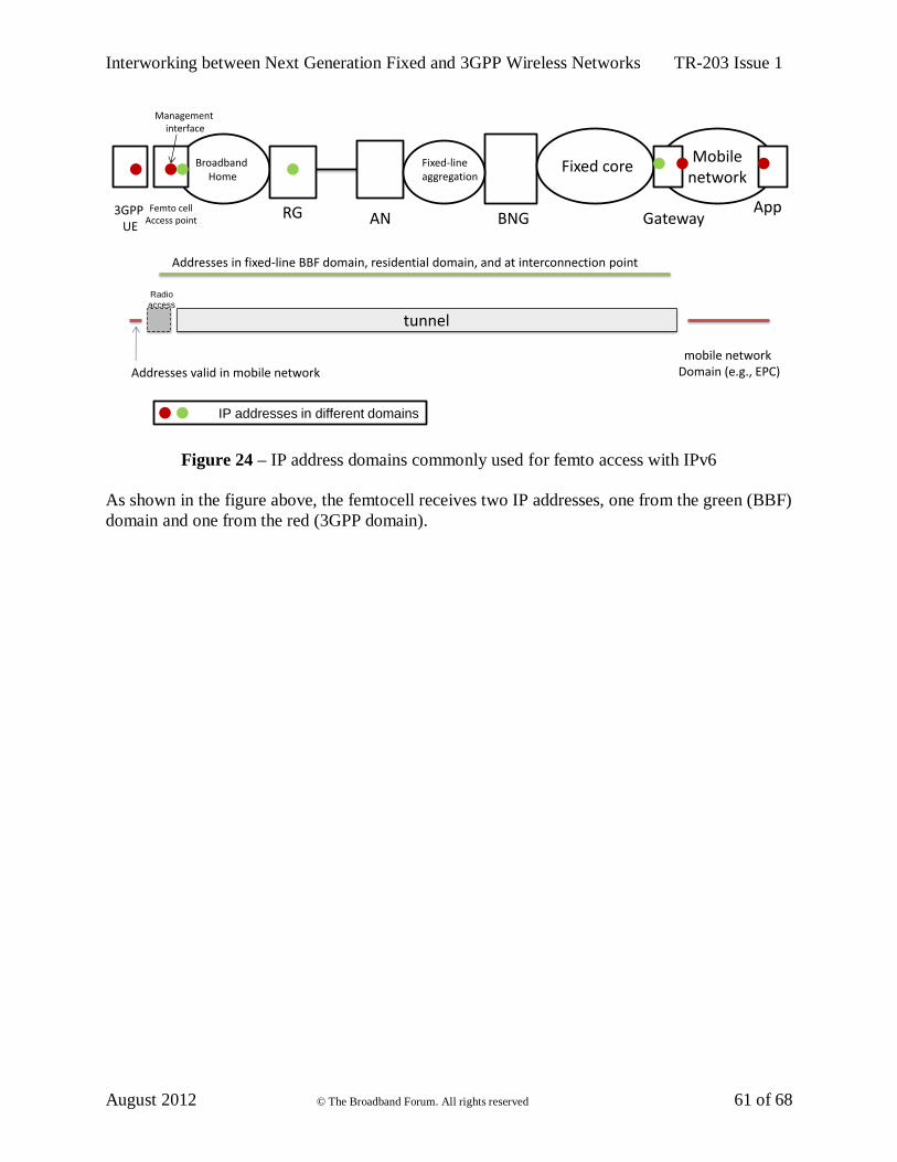
Interworking between Next Generation Fixed and 3GPP Wireless Networks TR-203 Issue 1
August 2012 © The Broadband Forum. All rights reserved 61 of 68
AN BNGRG
Fixed coreFixed-lineaggregation
Broadband Home
3GPP UE
Mobile network
Gateway
Addresses valid in mobile network
App
tunnel
mobile network Domain (e.g., EPC)
Femto cellAccess point
Radio
access
IP addresses in different domains
Management interface
Addresses in fixed-line BBF domain, residential domain, and at interconnection point
Figure 24 – IP address domains commonly used for femto access with IPv6
As shown in the figure above, the femtocell receives two IP addresses, one from the green (BBF)
domain and one from the red (3GPP domain).

Interworking between Next Generation Fixed and 3GPP Wireless Networks TR-203 Issue 1
August 2012 © The Broadband Forum. All rights reserved 62 of 68
Appendix III. QoS Interworking
GSMA document IR.34 [18] defines the recommended mapping of traffic classes to DSCP
values over IP interconnection network between network operators for roaming purposes.
RFC4594 [22] also provides a recommended relationship between traffic classes and DSCP
assignment. The objective is to enable wireless sessions to be transported between wireless
access and egress networks via an IP backbone network (this is the so-called IPX). The latter
utilizes DSCP values to specify the desired QoS in the IP domain. Hence there is translation at
the interfaces between the IP backbone and the wireless access and egress networks where the
UMTS and LTE QCI values are mapped into DSCP values. Taking into account the relationship
between QoS characteristics (including traffic classes) and 3GPP QCI values defined in TS
23.203 [6], Table 3 shows an example of mapping of QCI values into DSCP values.

Interworking between Next Generation Fixed and 3GPP Wireless Networks TR-203 Issue 1
August 2012 © The Broadband Forum. All rights reserved 63 of 68
Table 3 – QCI to DSPC mapping based on 3GPP TS 23.203 and RFC 4594
QCI Resource
Type Priority
Packet
Delay
Budget
Packet
Error
Loss
Rate
UMTS QoS
Parameters Example
Services
Diffserv
Peer-Hop
Behaviour
DSCP code Traffic Class THP
1
GBR
2 100 ms 10-2 Conversational N/A Conversational
Voice EF
101110, 101100
2 4 150 ms 10-3
Conversational N/A Conversational
Video (Live
Streaming)
AF41/AF42/
AF43
100010,100100,
100110
3 3 50 ms 10-3 Streaming N/A Real Time
Gaming CS5
101000, 101001
4 5 300 ms 10-6
Streaming N/A Non-
Conversational
Video
(Buffered
Streaming)
CS3
011000, 011001
5
Non-
GBR
1 100 ms 10-6 Interactive 1 IMS Signalling A/V-Sig 010001
6 6
300 ms 10-6
Interactive 1 Video
(Buffered
Streaming)
TCP-based
(e.g., www, e-
mail, chat, ftp,
p2p file
sharing,
progressive
video, etc.)
AF31/AF32/
AF33
011010,011100,
011110
7 7 100 ms
10-3
Interactive 2 Voice,Video
(Live
Streaming)
Interactive
Gaming
AF21/AF22/
AF23
011010,011100,
011110
8 8
300ms 10-6
Interactive 3 Video
(Buffered
Streaming)
TCP-based
(e.g., www, e-
mail, chat, ftp,
p2p file
sharing,
progressive
video, etc.)
AF11/AF12/
AF13
001010,001100,
001110
9 9
Background N/A
DF/CS0
000000
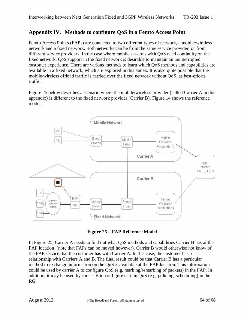
Interworking between Next Generation Fixed and 3GPP Wireless Networks TR-203 Issue 1
August 2012 © The Broadband Forum. All rights reserved 64 of 68
Appendix IV. Methods to configure QoS in a Femto Access Point
Femto Access Points (FAPs) are connected to two different types of network, a mobile/wireless
network and a fixed network. Both networks can be from the same service provider, or from
different service providers. In the case where mobile sessions with QoS need continuity on the
fixed network, QoS support in the fixed network is desirable to maintain an uninterrupted
customer experience. There are various methods to learn which QoS methods and capabilities are
available in a fixed network, which are explored in this annex. It is also quite possible that the
mobile/wireless offload traffic is carried over the fixed network without QoS, as best-efforts
traffic.
Figure 25 below describes a scenario where the mobile/wireless provider (called Carrier A in this
appendix) is different to the fixed network provider (Carrier B). Figure 14 shows the reference
model.
Figure 25 – FAP Reference Model
In Figure 25, Carrier A needs to find out what QoS methods and capabilities Carrier B has at the
FAP location (note that FAPs can be moved however). Carrier B would otherwise not know of
the FAP service that the customer has with Carrier A. In this case, the customer has a
relationship with Carriers A and B. The final result could be that Carrier B has a particular
method to exchange information on the QoS is available at the FAP location. This information
could be used by carrier A to configure QoS (e.g. marking/remarking of packets) in the FAP. In
addition, it may be used by carrier B to configure certain QoS (e.g. policing, scheduling) in the
RG.

Interworking between Next Generation Fixed and 3GPP Wireless Networks TR-203 Issue 1
August 2012 © The Broadband Forum. All rights reserved 65 of 68
Fixed network providers may not have a homogeneous set of QoS capabilities across the entirety
network segments of their network. Even where they do, there may still be differences between
different fixed network service providers.
Each time the FAP boots up in a different location, the following processes need to be executed:
1. Registration (including Relocation/Re-registration). A FAP needs to register its location
(e.g. via GPS) with Carrier A. Carrier A needs to know the location of the customer in
some cases, e.g. for (emergency calls. Carrier A may also learn whether or not this
customer is connected to a fixed network provided by the same carrier. In the former
case, none of the following steps may be needed. However, in this scenario it is assumed
that the customer is connected to carrier B for fixed network services, in which case the
next steps are needed. A first time registration could result in a QoS mapping table (e.g.
which markings to use for which packets) for the FAP. A change of location of the FAP
(relocation) may or may not result in a new QoS mapping table for the FAP.
2. Carrier A learns who Carrier B is, and what QoS Carrier B has in the location of the
common customer. This could be static information, e.g. the customer could specify this
manually; however, this annex explores an electronic/automated method. For example,
for a FAP to stream its data over the fixed network back to the wireless/mobile network,
the public IP address of the secure tunnel end-point of the RG could be used. By means
of established DNS methods (e.g. reverse lookup), Carrier A can find out who carrier B is
(domain or Fully Qualified Domain Name). Service records (SRV records), described in
IETF RFC 2782 [20], specify data in the Domain Name System defining the location, i.e.
the hostname and port number of carrier B’s services. For example, Carrier B could share
QoS information based on requests made to a web server indicated via an SRV record for
the ISP. Similarly, DNS could use an SRV record to learn about physical geo-location of
the RG or FAPs.
3. Determine if carrier B offers QoS. Once Carrier A learns how to communicate with
Carrier B regarding QoS. Carrier A needs to know whether Carrier B supports QoS in the
location of the customer’s FAP. Here it is assumed that Carrier B will not expose an
entire network map to Carrier A with all the QoS details of its network footprint, (which
could change over time – albeit slowly) but will support some form of a query interface
for location specific QoS questions. The answer could simply be yes or no. If the answer
is no, then the process can stop. However, if the answer is yes, the next step would apply.
4. Determine whether the customer needs to purchase a different service package with
carrier B to support the FAP traffic. This may be needed to ensure that Carrier B can
fulfill the QoS needs from a bandwidth perspective. It is possible that the customer has
subscribed to the lowest speed tier with Carrier B and now wants to support a FAP that
exceeds the bandwidth capabilities of the lowest speed tier of the customers bandwidth
cap. Carrier A may respond with the max number of simultaneous sessions supported and
bandwidth as per Carrier A’s service with the customer.
Interworking between Next Generation Fixed and 3GPP Wireless Networks TR-203 Issue 1
August 2012 © The Broadband Forum. All rights reserved 66 of 68
5. Determining the QoS mechanism with Carrier B (at the customer location): Static or
Dynamic. Carrier B may have various methods to request QoS. One method could be a
static configuration (e.g. an OSS/NMS) method. Figure 26 shows possible interactions
between Carrier A and Carrier B in the case where Carrier B supports a static method
only. Figure 27 shows possible interactions between Carrier A and B in case Carrier B
supports a dynamic/signaled (e.g. by means of policy control interworking through S9a).
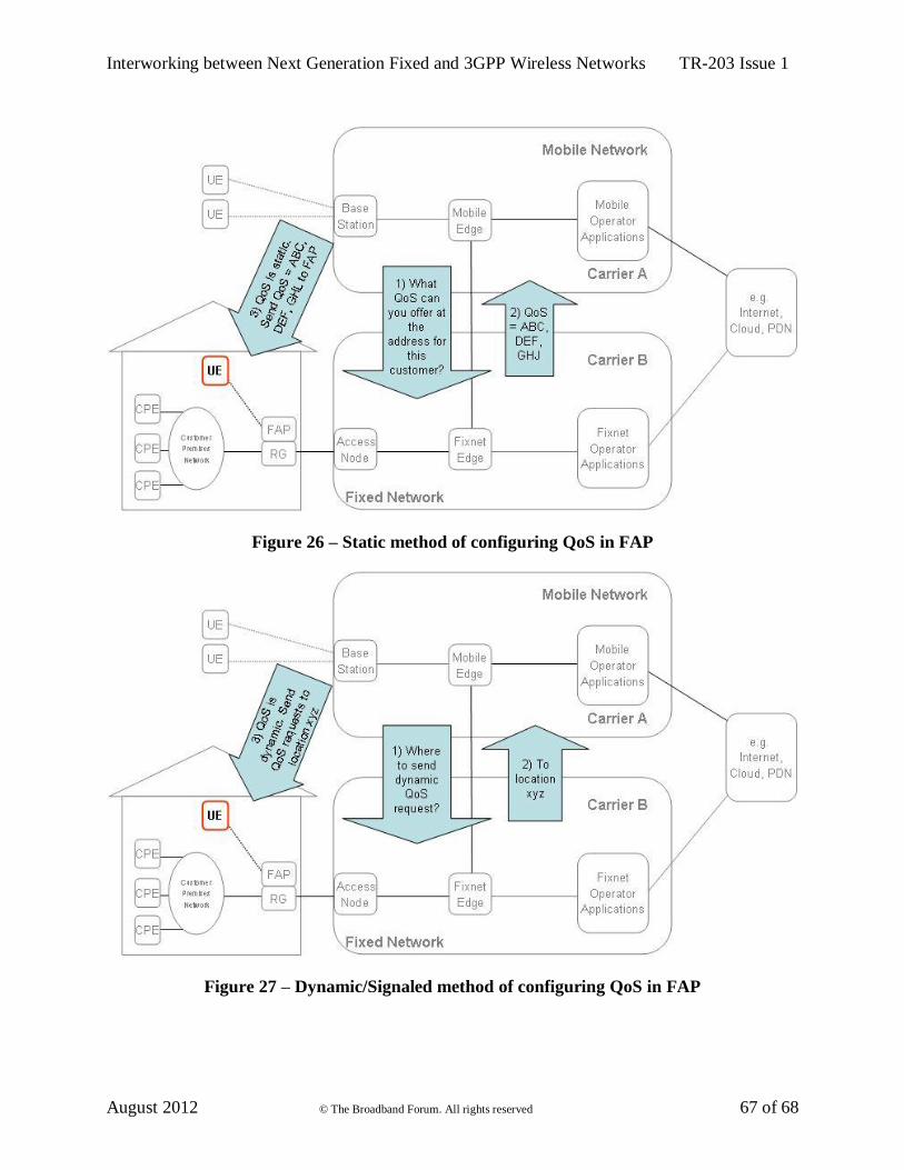
Interworking between Next Generation Fixed and 3GPP Wireless Networks TR-203 Issue 1
August 2012 © The Broadband Forum. All rights reserved 67 of 68
Figure 26 – Static method of configuring QoS in FAP
Figure 27 – Dynamic/Signaled method of configuring QoS in FAP
Interworking between Next Generation Fixed and 3GPP Wireless Networks TR-203 Issue 1
August 2012 © The Broadband Forum. All rights reserved 68 of 68
6. Methods to configure the FAP in the case of static QoS mechanism or dynamic QoS
mechanism. In this case, a QoS mapping table may be pushed (e.g. via TR-069 [12]) into
the FAP. Figure 26 and Figure 27 shows the type of communication for this purpose.
End of Broadband Forum Technical Report TR-203