tr-450xl-4 - tadano
TRANSCRIPT
TR-450XL-4TR-450XL-4TR-450XL-4TR-450XL-4TR-450XL-4TR-450XL-4TR-450XL-4TR-450XL-4TR-450XL-4TR-450XL-4TR-450XL-4TR-450XL-4TR-450XL-4TR-450XL-4TR-450XL-4TR-450XL-4TR-450XL-4TR-450XL-4TR-450XL-4TR-450XL-4TR-450XL-4TR-450XL-4TR-450XL-4TR-450XL-445 Ton Capacity (40.8 Metric Tons)
TR-450XL-445 Ton Capacity (40.8 Metric Tons)
TR-450XL-445 Ton Capacity (40.8 Metric Tons)
TR-450XL-445 Ton Capacity (40.8 Metric Tons)45 Ton Capacity (40.8 Metric Tons)45 Ton Capacity (40.8 Metric Tons)45 Ton Capacity (40.8 Metric Tons)45 Ton Capacity (40.8 Metric Tons)45 Ton Capacity (40.8 Metric Tons)45 Ton Capacity (40.8 Metric Tons)45 Ton Capacity (40.8 Metric Tons)45 Ton Capacity (40.8 Metric Tons)45 Ton Capacity (40.8 Metric Tons)45 Ton Capacity (40.8 Metric Tons)45 Ton Capacity (40.8 Metric Tons)45 Ton Capacity (40.8 Metric Tons)45 Ton Capacity (40.8 Metric Tons)45 Ton Capacity (40.8 Metric Tons)45 Ton Capacity (40.8 Metric Tons)
HYDRAULIC ROUGH TERRAIN CRANEHYDRAULIC ROUGH TERRAIN CRANEHYDRAULIC ROUGH TERRAIN CRANEHYDRAULIC ROUGH TERRAIN CRANEHYDRAULIC ROUGH TERRAIN CRANEHYDRAULIC ROUGH TERRAIN CRANEHYDRAULIC ROUGH TERRAIN CRANEHYDRAULIC ROUGH TERRAIN CRANEHYDRAULIC ROUGH TERRAIN CRANEHYDRAULIC ROUGH TERRAIN CRANEHYDRAULIC ROUGH TERRAIN CRANEHYDRAULIC ROUGH TERRAIN CRANEHYDRAULIC ROUGH TERRAIN CRANEHYDRAULIC ROUGH TERRAIN CRANEHYDRAULIC ROUGH TERRAIN CRANEHYDRAULIC ROUGH TERRAIN CRANEHYDRAULIC ROUGH TERRAIN CRANEHYDRAULIC ROUGH TERRAIN CRANEHYDRAULIC ROUGH TERRAIN CRANE
DIMENSIONSDIMENSIONSDIMENSIONSDIMENSIONSDIMENSIONSDIMENSIONSDIMENSIONSDIMENSIONSDIMENSIONSDIMENSIONSDIMENSIONSDIMENSIONSDIMENSIONSDIMENSIONSDIMENSIONS
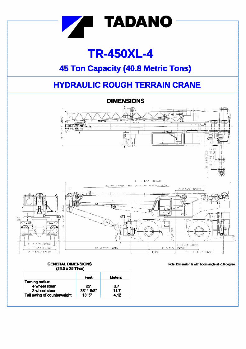
GENERAL DIMENSIONS (23.5 x 25 Tires)
Feet MetersTurning radius: 4 wheel steer 22' 6.7 2 wheel steer 38' 4-5/8" 11.7Tail swing of counterweight 13' 5" 4.12
GENERAL DIMENSIONS (23.5 x 25 Tires)
Feet MetersTurning radius: 4 wheel steer 22' 6.7 2 wheel steer 38' 4-5/8" 11.7Tail swing of counterweight 13' 5" 4.12
Note: Dimension is with boom angle at -0.8 degree. GENERAL DIMENSIONS (23.5 x 25 Tires)
Feet MetersTurning radius: 4 wheel steer 22' 6.7 2 wheel steer 38' 4-5/8" 11.7Tail swing of counterweight 13' 5" 4.12
Note: Dimension is with boom angle at -0.8 degree. GENERAL DIMENSIONS (23.5 x 25 Tires)
Feet MetersTurning radius: 4 wheel steer 22' 6.7 2 wheel steer 38' 4-5/8" 11.7Tail swing of counterweight 13' 5" 4.12
Note: Dimension is with boom angle at -0.8 degree. GENERAL DIMENSIONS (23.5 x 25 Tires)
Feet MetersTurning radius: 4 wheel steer 22' 6.7 2 wheel steer 38' 4-5/8" 11.7Tail swing of counterweight 13' 5" 4.12
Note: Dimension is with boom angle at -0.8 degree. GENERAL DIMENSIONS (23.5 x 25 Tires)
Feet MetersTurning radius: 4 wheel steer 22' 6.7 2 wheel steer 38' 4-5/8" 11.7Tail swing of counterweight 13' 5" 4.12
Note: Dimension is with boom angle at -0.8 degree. GENERAL DIMENSIONS (23.5 x 25 Tires)
Feet MetersTurning radius: 4 wheel steer 22' 6.7 2 wheel steer 38' 4-5/8" 11.7Tail swing of counterweight 13' 5" 4.12
Note: Dimension is with boom angle at -0.8 degree. GENERAL DIMENSIONS (23.5 x 25 Tires)
Feet MetersTurning radius: 4 wheel steer 22' 6.7 2 wheel steer 38' 4-5/8" 11.7Tail swing of counterweight 13' 5" 4.12
Note: Dimension is with boom angle at -0.8 degree. GENERAL DIMENSIONS (23.5 x 25 Tires)
Feet MetersTurning radius: 4 wheel steer 22' 6.7 2 wheel steer 38' 4-5/8" 11.7Tail swing of counterweight 13' 5" 4.12
GENERAL DIMENSIONS (23.5 x 25 Tires)
Feet MetersTurning radius: 4 wheel steer 22' 6.7 2 wheel steer 38' 4-5/8" 11.7Tail swing of counterweight 13' 5" 4.12
GENERAL DIMENSIONS (23.5 x 25 Tires)
Feet MetersTurning radius: 4 wheel steer 22' 6.7 2 wheel steer 38' 4-5/8" 11.7Tail swing of counterweight 13' 5" 4.12
GENERAL DIMENSIONS (23.5 x 25 Tires)
Feet MetersTurning radius: 4 wheel steer 22' 6.7 2 wheel steer 38' 4-5/8" 11.7Tail swing of counterweight 13' 5" 4.12
GENERAL DIMENSIONS (23.5 x 25 Tires)
Feet MetersTurning radius: 4 wheel steer 22' 6.7 2 wheel steer 38' 4-5/8" 11.7Tail swing of counterweight 13' 5" 4.12
GENERAL DIMENSIONS (23.5 x 25 Tires)
Feet MetersTurning radius: 4 wheel steer 22' 6.7 2 wheel steer 38' 4-5/8" 11.7Tail swing of counterweight 13' 5" 4.12
GENERAL DIMENSIONS (23.5 x 25 Tires)
Feet MetersTurning radius: 4 wheel steer 22' 6.7 2 wheel steer 38' 4-5/8" 11.7Tail swing of counterweight 13' 5" 4.12
GENERAL DIMENSIONS (23.5 x 25 Tires)
Feet MetersTurning radius: 4 wheel steer 22' 6.7 2 wheel steer 38' 4-5/8" 11.7Tail swing of counterweight 13' 5" 4.12
GENERAL DIMENSIONS (23.5 x 25 Tires)
Feet MetersTurning radius: 4 wheel steer 22' 6.7 2 wheel steer 38' 4-5/8" 11.7Tail swing of counterweight 13' 5" 4.12
GENERAL DIMENSIONS (23.5 x 25 Tires)
Feet MetersTurning radius: 4 wheel steer 22' 6.7 2 wheel steer 38' 4-5/8" 11.7Tail swing of counterweight 13' 5" 4.12
GENERAL DIMENSIONS (23.5 x 25 Tires)
Feet MetersTurning radius: 4 wheel steer 22' 6.7 2 wheel steer 38' 4-5/8" 11.7Tail swing of counterweight 13' 5" 4.12
GENERAL DIMENSIONS (23.5 x 25 Tires)
Feet MetersTurning radius: 4 wheel steer 22' 6.7 2 wheel steer 38' 4-5/8" 11.7Tail swing of counterweight 13' 5" 4.12
GENERAL DIMENSIONS (23.5 x 25 Tires)
Feet MetersTurning radius: 4 wheel steer 22' 6.7 2 wheel steer 38' 4-5/8" 11.7Tail swing of counterweight 13' 5" 4.12
GENERAL DIMENSIONS (23.5 x 25 Tires)
Feet MetersTurning radius: 4 wheel steer 22' 6.7 2 wheel steer 38' 4-5/8" 11.7Tail swing of counterweight 13' 5" 4.12
GENERAL DIMENSIONS (23.5 x 25 Tires)
Feet MetersTurning radius: 4 wheel steer 22' 6.7 2 wheel steer 38' 4-5/8" 11.7Tail swing of counterweight 13' 5" 4.12
GENERAL DIMENSIONS (23.5 x 25 Tires)
Feet MetersTurning radius: 4 wheel steer 22' 6.7 2 wheel steer 38' 4-5/8" 11.7Tail swing of counterweight 13' 5" 4.12
GENERAL DIMENSIONS (23.5 x 25 Tires)
Feet MetersTurning radius: 4 wheel steer 22' 6.7 2 wheel steer 38' 4-5/8" 11.7Tail swing of counterweight 13' 5" 4.12
GENERAL DIMENSIONS (23.5 x 25 Tires)
Feet MetersTurning radius: 4 wheel steer 22' 6.7 2 wheel steer 38' 4-5/8" 11.7Tail swing of counterweight 13' 5" 4.12
GENERAL DIMENSIONS (23.5 x 25 Tires)
Feet MetersTurning radius: 4 wheel steer 22' 6.7 2 wheel steer 38' 4-5/8" 11.7Tail swing of counterweight 13' 5" 4.12
GENERAL DIMENSIONS (23.5 x 25 Tires)
Feet MetersTurning radius: 4 wheel steer 22' 6.7 2 wheel steer 38' 4-5/8" 11.7Tail swing of counterweight 13' 5" 4.12
GENERAL DIMENSIONS (23.5 x 25 Tires)
Feet MetersTurning radius: 4 wheel steer 22' 6.7 2 wheel steer 38' 4-5/8" 11.7Tail swing of counterweight 13' 5" 4.12
GENERAL DIMENSIONS (23.5 x 25 Tires)
Feet MetersTurning radius: 4 wheel steer 22' 6.7 2 wheel steer 38' 4-5/8" 11.7Tail swing of counterweight 13' 5" 4.12
GENERAL DIMENSIONS (23.5 x 25 Tires)
Feet MetersTurning radius: 4 wheel steer 22' 6.7 2 wheel steer 38' 4-5/8" 11.7Tail swing of counterweight 13' 5" 4.12
GENERAL DIMENSIONS (23.5 x 25 Tires)
Feet MetersTurning radius: 4 wheel steer 22' 6.7 2 wheel steer 38' 4-5/8" 11.7Tail swing of counterweight 13' 5" 4.12
GENERAL DIMENSIONS (23.5 x 25 Tires)
Feet MetersTurning radius: 4 wheel steer 22' 6.7 2 wheel steer 38' 4-5/8" 11.7Tail swing of counterweight 13' 5" 4.12
GENERAL DIMENSIONS (23.5 x 25 Tires)
Feet MetersTurning radius: 4 wheel steer 22' 6.7 2 wheel steer 38' 4-5/8" 11.7Tail swing of counterweight 13' 5" 4.12
GENERAL DIMENSIONS (23.5 x 25 Tires)
Feet MetersTurning radius: 4 wheel steer 22' 6.7 2 wheel steer 38' 4-5/8" 11.7Tail swing of counterweight 13' 5" 4.12
GENERAL DIMENSIONS (23.5 x 25 Tires)
Feet MetersTurning radius: 4 wheel steer 22' 6.7 2 wheel steer 38' 4-5/8" 11.7Tail swing of counterweight 13' 5" 4.12
GENERAL DIMENSIONS (23.5 x 25 Tires)
Feet MetersTurning radius: 4 wheel steer 22' 6.7 2 wheel steer 38' 4-5/8" 11.7Tail swing of counterweight 13' 5" 4.12
GENERAL DIMENSIONS (23.5 x 25 Tires)
Feet MetersTurning radius: 4 wheel steer 22' 6.7 2 wheel steer 38' 4-5/8" 11.7Tail swing of counterweight 13' 5" 4.12
GENERAL DIMENSIONS (23.5 x 25 Tires)
Feet MetersTurning radius: 4 wheel steer 22' 6.7 2 wheel steer 38' 4-5/8" 11.7Tail swing of counterweight 13' 5" 4.12
GENERAL DIMENSIONS (23.5 x 25 Tires)
Feet MetersTurning radius: 4 wheel steer 22' 6.7 2 wheel steer 38' 4-5/8" 11.7Tail swing of counterweight 13' 5" 4.12
GENERAL DIMENSIONS (23.5 x 25 Tires)
Feet MetersTurning radius: 4 wheel steer 22' 6.7 2 wheel steer 38' 4-5/8" 11.7Tail swing of counterweight 13' 5" 4.12
GENERAL DIMENSIONS (23.5 x 25 Tires)
Feet MetersTurning radius: 4 wheel steer 22' 6.7 2 wheel steer 38' 4-5/8" 11.7Tail swing of counterweight 13' 5" 4.12
GENERAL DIMENSIONS (23.5 x 25 Tires)
Feet MetersTurning radius: 4 wheel steer 22' 6.7 2 wheel steer 38' 4-5/8" 11.7Tail swing of counterweight 13' 5" 4.12
GENERAL DIMENSIONS (23.5 x 25 Tires)
Feet MetersTurning radius: 4 wheel steer 22' 6.7 2 wheel steer 38' 4-5/8" 11.7Tail swing of counterweight 13' 5" 4.12
GENERAL DIMENSIONS (23.5 x 25 Tires)
Feet MetersTurning radius: 4 wheel steer 22' 6.7 2 wheel steer 38' 4-5/8" 11.7Tail swing of counterweight 13' 5" 4.12
GENERAL DIMENSIONS (23.5 x 25 Tires)
Feet MetersTurning radius: 4 wheel steer 22' 6.7 2 wheel steer 38' 4-5/8" 11.7Tail swing of counterweight 13' 5" 4.12
GENERAL DIMENSIONS (23.5 x 25 Tires)
Feet MetersTurning radius: 4 wheel steer 22' 6.7 2 wheel steer 38' 4-5/8" 11.7Tail swing of counterweight 13' 5" 4.12
GENERAL DIMENSIONS (23.5 x 25 Tires)
Feet MetersTurning radius: 4 wheel steer 22' 6.7 2 wheel steer 38' 4-5/8" 11.7Tail swing of counterweight 13' 5" 4.12
GENERAL DIMENSIONS (23.5 x 25 Tires)
Feet MetersTurning radius: 4 wheel steer 22' 6.7 2 wheel steer 38' 4-5/8" 11.7Tail swing of counterweight 13' 5" 4.12
GENERAL DIMENSIONS (23.5 x 25 Tires)
Feet MetersTurning radius: 4 wheel steer 22' 6.7 2 wheel steer 38' 4-5/8" 11.7Tail swing of counterweight 13' 5" 4.12
GENERAL DIMENSIONS (23.5 x 25 Tires)
Feet MetersTurning radius: 4 wheel steer 22' 6.7 2 wheel steer 38' 4-5/8" 11.7Tail swing of counterweight 13' 5" 4.12
GENERAL DIMENSIONS (23.5 x 25 Tires)
Feet MetersTurning radius: 4 wheel steer 22' 6.7 2 wheel steer 38' 4-5/8" 11.7Tail swing of counterweight 13' 5" 4.12
GENERAL DIMENSIONS (23.5 x 25 Tires)
Feet MetersTurning radius: 4 wheel steer 22' 6.7 2 wheel steer 38' 4-5/8" 11.7Tail swing of counterweight 13' 5" 4.12
GENERAL DIMENSIONS (23.5 x 25 Tires)
Feet MetersTurning radius: 4 wheel steer 22' 6.7 2 wheel steer 38' 4-5/8" 11.7Tail swing of counterweight 13' 5" 4.12
GENERAL DIMENSIONS (23.5 x 25 Tires)
Feet MetersTurning radius: 4 wheel steer 22' 6.7 2 wheel steer 38' 4-5/8" 11.7Tail swing of counterweight 13' 5" 4.12
GENERAL DIMENSIONS (23.5 x 25 Tires)
Feet MetersTurning radius: 4 wheel steer 22' 6.7 2 wheel steer 38' 4-5/8" 11.7Tail swing of counterweight 13' 5" 4.12
GENERAL DIMENSIONS (23.5 x 25 Tires)
Feet MetersTurning radius: 4 wheel steer 22' 6.7 2 wheel steer 38' 4-5/8" 11.7Tail swing of counterweight 13' 5" 4.12
GENERAL DIMENSIONS (23.5 x 25 Tires)
Feet MetersTurning radius: 4 wheel steer 22' 6.7 2 wheel steer 38' 4-5/8" 11.7Tail swing of counterweight 13' 5" 4.12
GENERAL DIMENSIONS (23.5 x 25 Tires)
Feet MetersTurning radius: 4 wheel steer 22' 6.7 2 wheel steer 38' 4-5/8" 11.7Tail swing of counterweight 13' 5" 4.12
GENERAL DIMENSIONS (23.5 x 25 Tires)
Feet MetersTurning radius: 4 wheel steer 22' 6.7 2 wheel steer 38' 4-5/8" 11.7Tail swing of counterweight 13' 5" 4.12
GENERAL DIMENSIONS (23.5 x 25 Tires)
Feet MetersTurning radius: 4 wheel steer 22' 6.7 2 wheel steer 38' 4-5/8" 11.7Tail swing of counterweight 13' 5" 4.12
GENERAL DIMENSIONS (23.5 x 25 Tires)
Feet MetersTurning radius: 4 wheel steer 22' 6.7 2 wheel steer 38' 4-5/8" 11.7Tail swing of counterweight 13' 5" 4.12
GENERAL DIMENSIONS (23.5 x 25 Tires)
Feet MetersTurning radius: 4 wheel steer 22' 6.7 2 wheel steer 38' 4-5/8" 11.7Tail swing of counterweight 13' 5" 4.12
GENERAL DIMENSIONS (23.5 x 25 Tires)
Feet MetersTurning radius: 4 wheel steer 22' 6.7 2 wheel steer 38' 4-5/8" 11.7Tail swing of counterweight 13' 5" 4.12
GENERAL DIMENSIONS (23.5 x 25 Tires)
Feet MetersTurning radius: 4 wheel steer 22' 6.7 2 wheel steer 38' 4-5/8" 11.7Tail swing of counterweight 13' 5" 4.12
GENERAL DIMENSIONS (23.5 x 25 Tires)
Feet MetersTurning radius: 4 wheel steer 22' 6.7 2 wheel steer 38' 4-5/8" 11.7Tail swing of counterweight 13' 5" 4.12
CRANE SPECIFICATIONSBOOM DRUM - Grooved 15-3/4"(0.40m) root diameter x 22-3/4"Four section full power synchronized telescoping boom, (0.578m) wide. Wire rope: 345' of 3/4"diameter rope (105m of33.5'~108.3' (10.2m~33m), of round hexagonal box construction 19mm). Drum capacity: 905' (276m) 6 layers. Maximum linewith four sheaves, 15-5/8" (0.396m) root diameter, at boom head. pull (permissible): 14,272lbs. (6,474kg)*. Maximum line speed:The synchronization system consists of a double acting telescope 534FPM (163m/min).cylinder, two extension cable and retraction cable. Hydraulic cylinder fitted with holding valve. Two easily removable wire rope * Maximum permissible line pull may be affected by wire ropeguards, rope dead end provided on both side of boom head. Strength.Boom telescope sections are supported by wear pads both vertically and horizontally. WIRE ROPE - Warrington seal wire, extra improved plow steel,
Preformed, independent wire rope core, right regular lay.BOOM ELEVATION - By a double acting hydraulic cylinder 3/4"(19 mm) 6X37 class
with holding valve. Elevation -0.8o~80o, combination controls forhand or foot operation. Boom angle indicator. HOOK BLOCKS
1. 45 ton (40.8 metric ton) - 4 sheaves with swivel hook andJIB - Double stage lattice type, 5o, 25o or 45o offset (tilt type). safety latch, for 3/4"(19mm) wire rope.Single sheave, 15-5/8"(0.396m) root diameter, at base and top jib 2. 5.5 ton (5.0 metric ton) - Weighted hook with swivel andhead. Stored alongside base boom section. Jib length is safety latch, for 3/4"(19mm) wire rope.28.9' (8.8m) or 50' (15.2m). Self stowing jib mounting pins.
AUXILIARY LIFTING SHEAVE (SINGLE TOP) (OPTIONAL) - HYDRAULIC SYSTEMSingle sheave, 17-5/16"(0.44m) root diameter. Mounted to mainboom head for single line work (stowable). PUMPS - Two variable piston pumps for crane functions.
Tandem gear pump for steering, swing and optional equipment.ANTI-TWO BLOCK - Pendant type over-winding cut out Powered by carrier engine. Pump disconnect for crane isdevice with audio-visual (FAILURE lamp/BUZZER) warning engaged/ disengaged by rotary switch from operator's cab.system.
CONTROL VALVES - Multiple valves actuated by pilotpressure with integral pressure relief valves.
SWINGHydraulic axial piston motor driven through planetary swing RESERVOIR - 148 gallon (560 lit.) capacity. External sight
speed reducer. Continuous 360o full circle swing on ball bearing level gauge.turntable at 2.7rpm. Equipped with manually locked/releasedswing brake. A swing lock (360o positive swing lock) for pick and FILTRATION - 26 micron return filter, full flow with bypasscarry and travel modes, manually engaged in cab. Twin swing protection, located inside of hydraulic reservoir. Accessible forSystem: Free swing or lock swing controlled by selector switch easy replacement.on right hand of front console.
OIL COOLER - Air cooled fan type.HOIST
MAIN HOIST - Variable speed type with grooved drum driven CAB AND CONTROLSby hydraulic axial piston motor through planetary winch speed reducer. Power load lowering and raising. Equipped with Both crane and drive operations can be performed from oneautomatic brake (neutral brake) and counterbalance valve. cab mounted on rotating superstructure.Controlled independently of auxiliary hoist. Equipped with cable follower and drum rotation indicator. Left side, 1 man type, steel construction with sliding door
access and safety glass windows opening at side. DoorDRUM - Grooved 15-3/4"(0.40m) root diameter x 22-3/4" window is powered control. Windshield glass window and roof(0.578m) wide. Wire rope: 597' of 3/4"diameter rope (182m of glass window are shatter-resistant. Tilt-telescoping steering 19mm). Drum capacity: 905' (276m) 6 layers. Maximum line wheel. Adjustable control lever stands for swing, boom hoist,pull (permissible): 14,272lbs. (6,474kg)*. Maximum line speed: boom telescoping, auxiliary hoist and main hoist. Control lever534FPM (163m/min). stands can change neutral positions and tilt for easy access to
cab. Engine throttle knob. Foot operated controls: boom hoist, AUXILIARY HOIST (OPTIONAL) - Variable speed type boom telescoping, service brake and engine throttle.with grooved drum by hydraulic axial piston motor throughplanetary winch speed reducer. Power load lowering and Dash-mounted engine start/stop, monitor lamps, cigaretteraising. Equipped with automatic brake (neutral brake) and lighter, drive selector switch, parking brake switch, steeringcounterbalance valve. Controlled independently of main hoist. mode select switch, power window switch, pump engaged/Equipped with cable follower and drum rotation indicator. disengaged switch, swing brake switch, telescoping/auxiliary
winch select switch, outrigger controls, swing free-lock selector switch and ashtray.
Instruments - Torque converter oil temperature, engine watertemperature, air pressure, fuel, speedometer, tachometer andhour meter. Hydraulic oil pressure is monitored and displayed on the AML-L display panel.
2
Tadano electronic LOAD MOMENT INDICATOR system Operator's right hand console includes transmission gear(AML-L) including: selector and sight level bubble. Upper console includes
Control lever lockout function working light switch, roof washer and wiper switch, oilLoad radius and/or boom angle and/or swing range cooler switch, emergency outrigger set up key switchpreset function and air conditioning control switch. Swing lock leverWarning buzzer and 3 way adjustable seat with high back and seat belt.Boom angle/boom length/jib offset angle/loadradius/rated lifting capacities/actual loads read outRatio of actual load moment to rated load moment NOTE:Each crane motion speed is based on unladenindication conditions.Slow elevation stop functionSlow swing stop function (swing range restricted only)Working condition register switchExternal warning lamp
TADANO AML-L monitors outrigger extended length andautomatically programs the corresponding "RATED LIFTINGCAPACITIES" table.
CARRIER SPECIFICATIONSSUSPENSION - Front: Semi-elliptic leaf springs with hydraulic
TYPE - Rear engine, left hand steering, driving axle 2-way lockout device. Rear: Semi-elliptic leaf springs with hydraulicselected type by manual switch, 4x2 front drive, 4x4 front and lockout device.rear drive.
BRAKE SYSTEMS - Service: Air over hydraulic disc brakes onFRAME - High tensile steel, all welded mono-box construction. all 4 wheels. Parking/Emergency: Spring applied-air released
brake acting on input shaft of front axle. Auxiliary: Electro-TRANSMISSION - Electronically controlled full automatic pneumatic operated exhaust brake.transmission. Torque converter driving full powershift withdriving axle selector. 6 forward and 2 reverse speeds, constant TIRES - 23.5-25 20PR(OR)mesh.
4 speeds - high range - 2 wheel drive; 4 wheel drive OUTRIGGERS - Four hydraulic, beam and jack outriggers.4 speeds - low range - 4 wheel drive Vertical jack cylinders equipped with integral holding valve. Each
outrigger beam and jack is controlled independently from cab.TRAVEL SPEED - 30 mph (48 km/h) Beams extend to 22'11-5/8" (7.0 m) center-line and retract to
within 9' 10-1/8" (3.0 m) overall width with floats. Outrigger jackAXLE - Front: Full floating type, steering and driving axle with floats are attached thus eliminating the need of manually planetary reduction. Rear: Full floating type, steering and driving attaching and detaching them. Controls and sight bubble locatedaxle with planetary reduction and non-spin rear differential. in upper structure cab. Three outrigger extension lengths are
provided with corresponding "RATED LIFTING CAPACITIES" forSTEERING- Hydraulic power steering controlled by steering crane duty in confined areas.wheel. Three steering modes available: 2 wheel front, 4 wheel Mid. Extension 16' 4-7/8" center to centercoordinated and 4 wheel crab. Mid. Extension 21' 3-7/8" center to center
Max. extension 22' 11-5/8" center to center
ENGINEModel Mitsubishi 6D16-TLEE Radiator Fin and tube core, thermostat controlledType Direct injection diesel Fan, in.(mm) Suction type, 6-blade, 23.6 (600) dia.No. of cylinders 6 Starting 24 voltCombustion 4 cycle, turbo charged and after cooled Charging 24 volt system, negative groundBoreXStroke, in.(mm) 4.646 X 4.528 (118X115) Battery 2-120 amp. HourDisplacement, cu. in (liters) 460 (7.545) Compressor, air, CFM(l /min) 9.2 CFM (260) at 2,800rpmAir inlet heater 24 volt preheat Horsepower (kW) Gross 223 (166) at 2,700rpmAir cleaner Dry type, replaceable element Torque, Max. ft-lb (kgm) 521 (72) at 1,300rpmOil filter Full flow with replaceable element Capacity, gal.(liters)Fuel filter Full flow with replaceable element Cooling water 3.4 (13)Fuel tank, gal.(liters) 79.2 (300), right side of carrier Lubrication 3.7 ~ 4.2 (14 ~ 16)Cooling Liquid pressurized, recirculating by-pass Fuel 79.2 (300)
3
- Four section full power synchronized boom 33.5'~108.3' - Tinted safety glass(10.2 m~33 m) - Front windshield wiper and washer
- 28.9'~50' (8.8 m~15.2 m) bi-fold lattice jib - Roof window wiper and washerwith 5o, 25o or 45o pinned offset (tilt type) with self storing pins. - Power window (Door of the cab)
- Auxiliary lifting sheave (single top) stowable - Rear view mirrors (right and left side)- Boom hoist foot control - Mirror for main and auxiliary hoists- Boom telescoping foot control - 3 way adjustable seat with high back and seat belt- Boom angle indicator - Tilt-telescoping steering wheel- Variable speed main hoist with grooved drum, cable follower - Self centering finger control levers with pilot control
and 597' of 3/4" cable. - Cab floor mat- Drum rotation indicator (thumper type) main and auxiliary hoist - Cigarette lighter- Tadano twin swing system - Back-up alarm- 360o positive swing lock - Low oil pressure/high water temp. warning device (visual)- 4 X 4 X 4 drive/steering - Rear steer centering light- Disc brakes - Fenders- Hydraulic lockout suspension - Air cleaner dust indicator- Non-spin rear differential - Towing hooks-Front and rear- 23.5-25 20PR (OR) tires - Lifting eyes- Independently controlled outriggers - Tool storage compartment- Three outrigger extension positions - Full instrumentation package- Self-storing outrigger pads - Pump disconnect in operator's cab- Outrigger extension length detector - Air dryer- Outrigger hose protection - Water separator with filter- Mitsubishi 6D16-TLEE turbo charged after cooled engine - Flood lights and work lights
(223HP) with exhaust brake - Tire inflation kit- Electronic controlled automatic transmission driven by torque - Hydraulic oil cooler
converter - 24 volt electric system- Engine over-run alarm - 45 ton (40.8 metric ton) 4 sheave hook block- Complete highway light package - 5.5 ton (5.0 metric ton) hook with swivel- Anti-Two block device (overwind cutout) - Hook block tie down (front bumper)- Electronic crane monitoring system - Weighted hook storage compartment- Tadano electronic load moment indicator system (AML-L)
including- Control lever lockout function- Working radius and/or boom angle and/or tip height and/or
swing range preset function- Warning buzzer - Variable speed auxiliary hoist with grooved drum, cable - Boom angle / boom length / jib offset angle / working radius / follower and 279' of 5/8" cable.
rated loads / actual loads read out - Hot water cab heater and air conditioner- Slow elevation stop function - Propane heater (less tank)- Slow swing stop function (swing range restricted only)- Working condition register switch- External warning lamp
HOISTING SPECIFICATIONSLINE SPEEDS AND PULLS DRUM WIRE ROPE CAPACITIES
F.P.M m/min Lbs. kgf Lbs. kgf Feet Meters Feet MetersHigh 367 112 15,698 7,121 14,272 6,474 123.0 37.5 123.0 37.5High 400 122 14,647 6,644 13,315 6,040 134.2 40.9 257.2 78.4High 433 132 13,520 6,133 12,292 5,576 145.3 44.3 402.5 122.7High 466 142 12,557 5,696 11,417 5,179 156.5 47.7 559.0 170.4High 502 153 11,721 5,317 10,657 4,834 167.7 51.1 726.7 221.5High 534 163 10,989 4,985 9,991 4,532 178.8 54.5 905.5 276.0
1 Developed by machinery with first layer of wire rope, but not based DRUM DIMENSIONSon rope strength or other limitation in machinery or equipment. Inch mm
2 Line speeds based only on hook block, not loaded. Root diameter 15-3/4" 4003 Sixth layer of wire rope is not recommended for hoisting Length 22-3/4" 578
operations. Flange diameter 25-3/8" 6454 Permissible line pull may be affected by wire rope strength.
6th35
4th
12nd
6
Wireropelayer
STANDARD EQUIPMENT
5th
3rd234
Layer Speed
1st
OPTIONAL EQUIPMENT
Main and auxiliary drum grooved lagging
Line speeds2 Line pulls 3/4" (19mm) wire ropeAvailable1 Permissible4
Rope per layer Total wire rope
Main or auxiliary hoist - 15'-3/4" (0.4m) drum
4
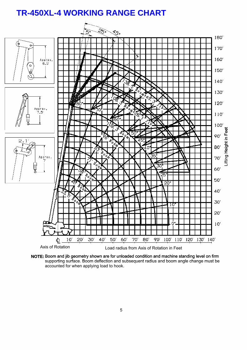
TR-450XL-4 WORKING RANGE CHART
Lift
ing
He
igh
t in
Fe
et
Lift
ing
He
igh
t in
Fe
et
Lift
ing
He
igh
t in
Fe
et
Boom and jib geometry shown are for unloaded condition and machine standing level on firmsupporting surface. Boom deflection and subsequent radius and boom angle change must beaccounted for when applying load to hook.
Load radius from Axis of Rotation in FeetAxis of Rotation
NOTE: Boom and jib geometry shown are for unloaded condition and machine standing level on firmsupporting surface. Boom deflection and subsequent radius and boom angle change must beaccounted for when applying load to hook.
NOTE:
5
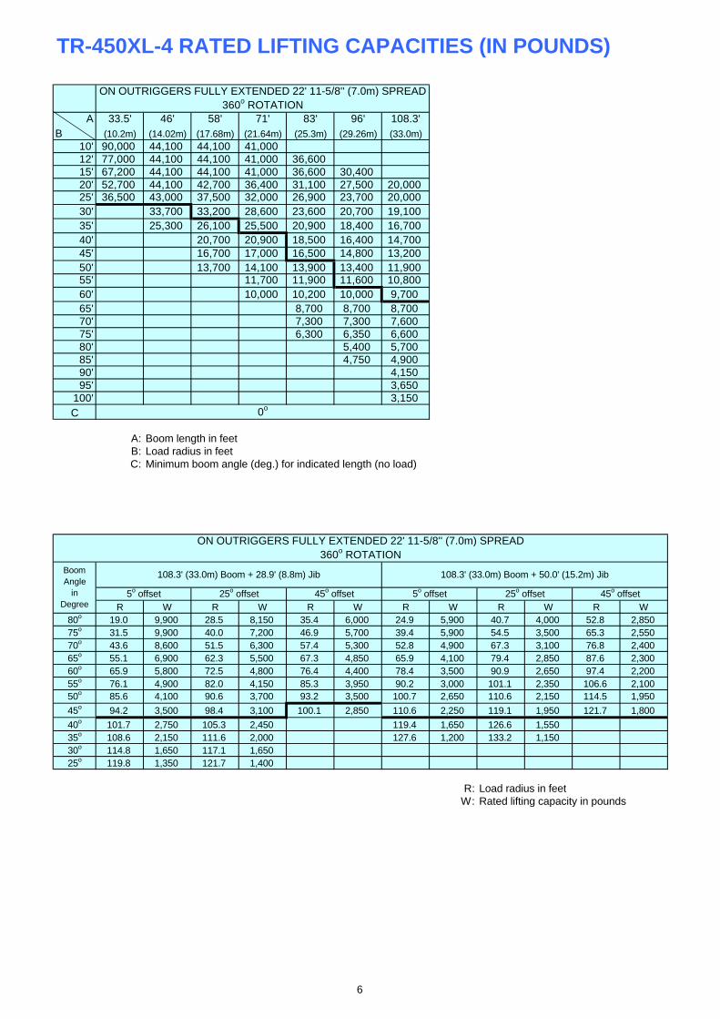
TR-450XL-4 RATED LIFTING CAPACITIES (IN POUNDS)
A 33.5' 46' 58' 71' 83' 96' 108.3'B (10.2m) (14.02m) (17.68m) (21.64m) (25.3m) (29.26m) (33.0m)
10' 90,000 44,100 44,100 41,00012' 77,000 44,100 44,100 41,000 36,60015' 67,200 44,100 44,100 41,000 36,600 30,40020' 52,700 44,100 42,700 36,400 31,100 27,500 20,00025' 36,500 43,000 37,500 32,000 26,900 23,700 20,00030' 33,700 33,200 28,600 23,600 20,700 19,10035' 25,300 26,100 25,500 20,900 18,400 16,70040' 20,700 20,900 18,500 16,400 14,70045' 16,700 17,000 16,500 14,800 13,20050' 13,700 14,100 13,900 13,400 11,90055' 11,700 11,900 11,600 10,80060' 10,000 10,200 10,000 9,70065' 8,700 8,700 8,70070' 7,300 7,300 7,60075' 6,300 6,350 6,60080' 5,400 5,70085' 4,750 4,90090' 4,15095' 3,650
100' 3,150C
A: Boom length in feetB: Load radius in feetC: Minimum boom angle (deg.) for indicated length (no load)
R W R W R W R W R W R W80o 19.0 9,900 28.5 8,150 35.4 6,000 24.9 5,900 40.7 4,000 52.8 2,85075o 31.5 9,900 40.0 7,200 46.9 5,700 39.4 5,900 54.5 3,500 65.3 2,55070o 43.6 8,600 51.5 6,300 57.4 5,300 52.8 4,900 67.3 3,100 76.8 2,40065o 55.1 6,900 62.3 5,500 67.3 4,850 65.9 4,100 79.4 2,850 87.6 2,30060o 65.9 5,800 72.5 4,800 76.4 4,400 78.4 3,500 90.9 2,650 97.4 2,20055o 76.1 4,900 82.0 4,150 85.3 3,950 90.2 3,000 101.1 2,350 106.6 2,10050o 85.6 4,100 90.6 3,700 93.2 3,500 100.7 2,650 110.6 2,150 114.5 1,950
45o 94.2 3,500 98.4 3,100 100.1 2,850 110.6 2,250 119.1 1,950 121.7 1,800
40o 101.7 2,750 105.3 2,450 119.4 1,650 126.6 1,55035o 108.6 2,150 111.6 2,000 127.6 1,200 133.2 1,15030o 114.8 1,650 117.1 1,65025o 119.8 1,350 121.7 1,400
R: Load radius in feetW: Rated lifting capacity in pounds
360o ROTATIONON OUTRIGGERS FULLY EXTENDED 22' 11-5/8'' (7.0m) SPREAD
0o
108.3' (33.0m) Boom + 28.9' (8.8m) Jib 108.3' (33.0m) Boom + 50.0' (15.2m) JibBoomAngle
inDegree
ON OUTRIGGERS FULLY EXTENDED 22' 11-5/8'' (7.0m) SPREAD360o ROTATION
5o offset 25o offset 5o offset 25o offset 45o offset45o offset
6
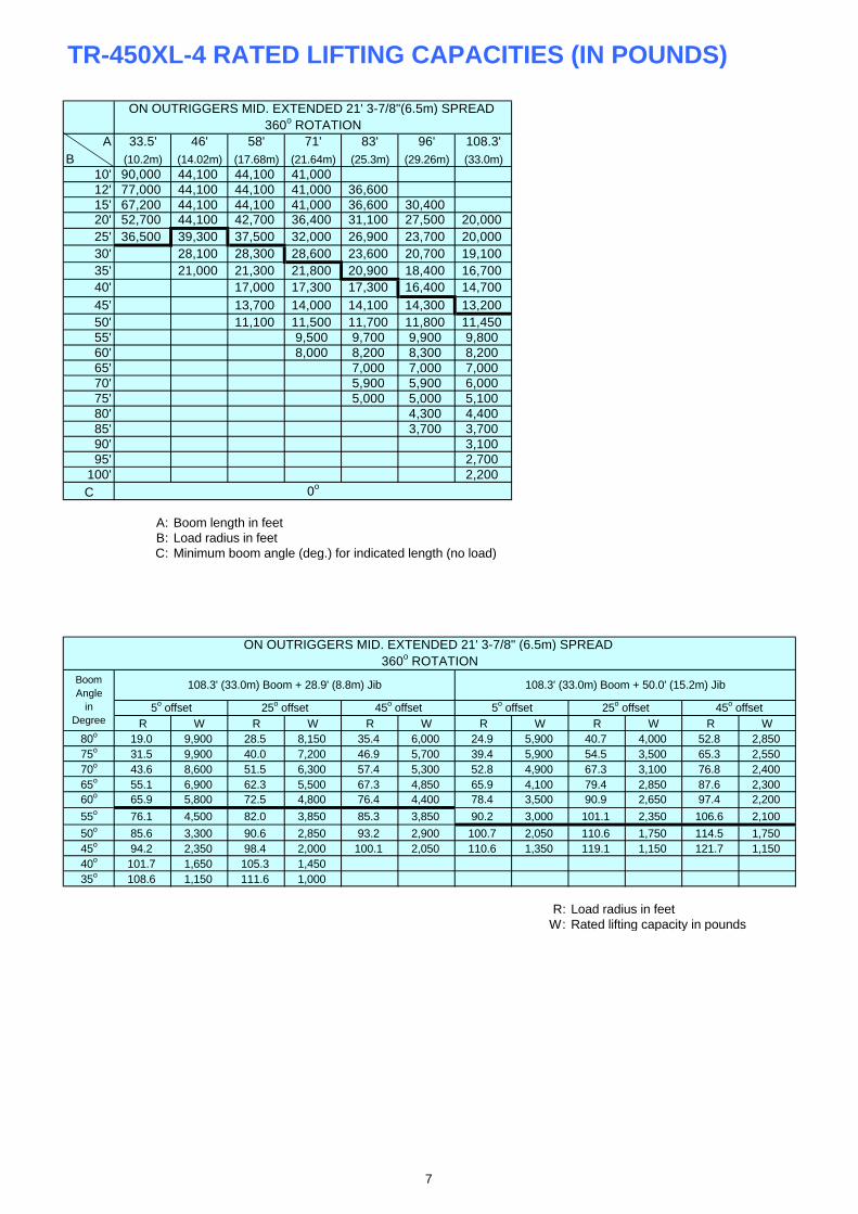
TR-450XL-4 RATED LIFTING CAPACITIES (IN POUNDS)
A 33.5' 46' 58' 71' 83' 96' 108.3'B (10.2m) (14.02m) (17.68m) (21.64m) (25.3m) (29.26m) (33.0m)
10' 90,000 44,100 44,100 41,00012' 77,000 44,100 44,100 41,000 36,60015' 67,200 44,100 44,100 41,000 36,600 30,40020' 52,700 44,100 42,700 36,400 31,100 27,500 20,00025' 36,500 39,300 37,500 32,000 26,900 23,700 20,00030' 28,100 28,300 28,600 23,600 20,700 19,10035' 21,000 21,300 21,800 20,900 18,400 16,70040' 17,000 17,300 17,300 16,400 14,70045' 13,700 14,000 14,100 14,300 13,20050' 11,100 11,500 11,700 11,800 11,45055' 9,500 9,700 9,900 9,80060' 8,000 8,200 8,300 8,20065' 7,000 7,000 7,00070' 5,900 5,900 6,00075' 5,000 5,000 5,10080' 4,300 4,40085' 3,700 3,70090' 3,10095' 2,700
100' 2,200C
A: Boom length in feetB: Load radius in feetC: Minimum boom angle (deg.) for indicated length (no load)
R W R W R W R W R W R W80o 19.0 9,900 28.5 8,150 35.4 6,000 24.9 5,900 40.7 4,000 52.8 2,85075o 31.5 9,900 40.0 7,200 46.9 5,700 39.4 5,900 54.5 3,500 65.3 2,55070o 43.6 8,600 51.5 6,300 57.4 5,300 52.8 4,900 67.3 3,100 76.8 2,40065o 55.1 6,900 62.3 5,500 67.3 4,850 65.9 4,100 79.4 2,850 87.6 2,30060o 65.9 5,800 72.5 4,800 76.4 4,400 78.4 3,500 90.9 2,650 97.4 2,200
55o 76.1 4,500 82.0 3,850 85.3 3,850 90.2 3,000 101.1 2,350 106.6 2,100
50o 85.6 3,300 90.6 2,850 93.2 2,900 100.7 2,050 110.6 1,750 114.5 1,75045o 94.2 2,350 98.4 2,000 100.1 2,050 110.6 1,350 119.1 1,150 121.7 1,15040o 101.7 1,650 105.3 1,45035o 108.6 1,150 111.6 1,000
R: Load radius in feetW: Rated lifting capacity in pounds
BoomAngle
inDegree
ON OUTRIGGERS MID. EXTENDED 21' 3-7/8" (6.5m) SPREAD 360o ROTATION
5o offset 25o offset 5o offset 25o offset 45o offset45o offset
360o ROTATIONON OUTRIGGERS MID. EXTENDED 21' 3-7/8"(6.5m) SPREAD
0o
108.3' (33.0m) Boom + 28.9' (8.8m) Jib 108.3' (33.0m) Boom + 50.0' (15.2m) Jib
7
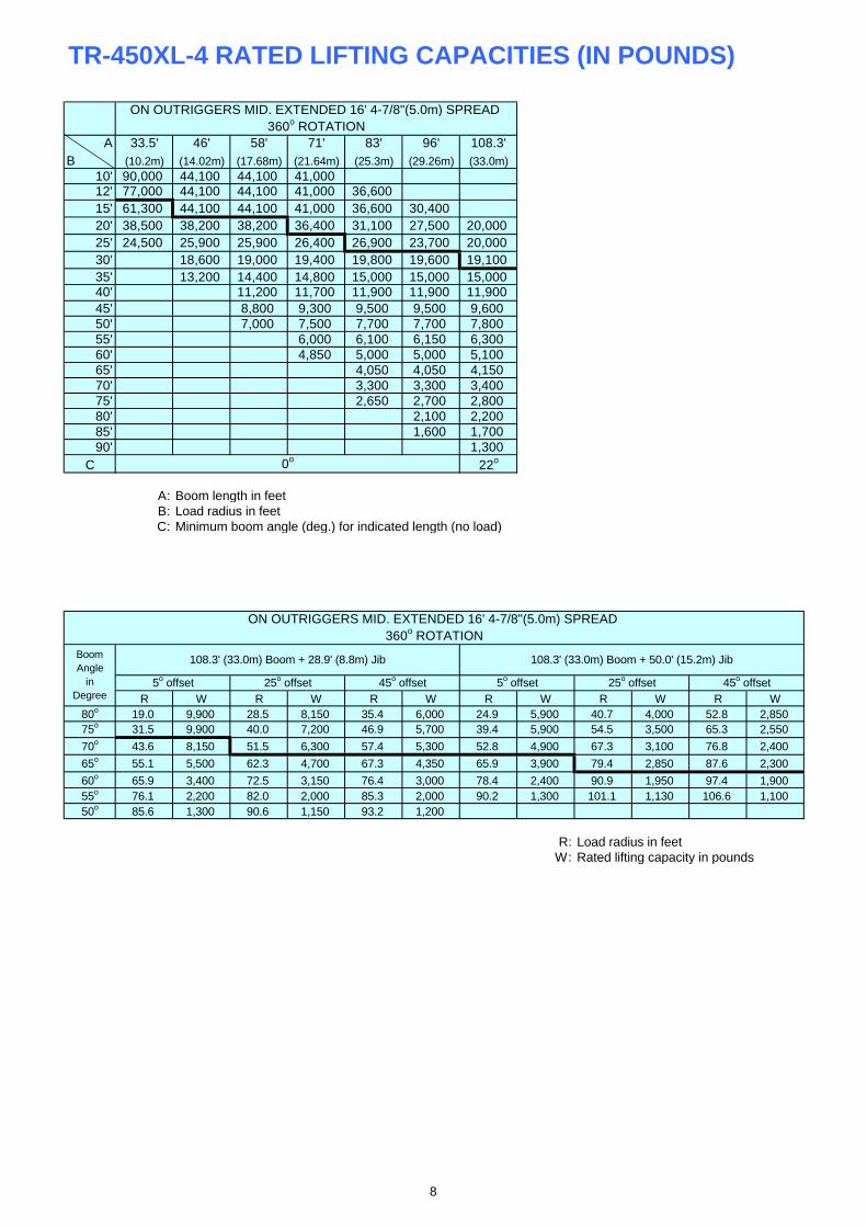
TR-450XL-4 RATED LIFTING CAPACITIES (IN POUNDS)
A 33.5' 46' 58' 71' 83' 96' 108.3'B (10.2m) (14.02m) (17.68m) (21.64m) (25.3m) (29.26m) (33.0m)
10' 90,000 44,100 44,100 41,00012' 77,000 44,100 44,100 41,000 36,60015' 61,300 44,100 44,100 41,000 36,600 30,40020' 38,500 38,200 38,200 36,400 31,100 27,500 20,00025' 24,500 25,900 25,900 26,400 26,900 23,700 20,00030' 18,600 19,000 19,400 19,800 19,600 19,10035' 13,200 14,400 14,800 15,000 15,000 15,00040' 11,200 11,700 11,900 11,900 11,90045' 8,800 9,300 9,500 9,500 9,60050' 7,000 7,500 7,700 7,700 7,80055' 6,000 6,100 6,150 6,30060' 4,850 5,000 5,000 5,10065' 4,050 4,050 4,15070' 3,300 3,300 3,40075' 2,650 2,700 2,80080' 2,100 2,20085' 1,600 1,70090' 1,300
C 22o
A: Boom length in feetB: Load radius in feetC: Minimum boom angle (deg.) for indicated length (no load)
R W R W R W R W R W R W80o 19.0 9,900 28.5 8,150 35.4 6,000 24.9 5,900 40.7 4,000 52.8 2,85075o 31.5 9,900 40.0 7,200 46.9 5,700 39.4 5,900 54.5 3,500 65.3 2,550
70o 43.6 8,150 51.5 6,300 57.4 5,300 52.8 4,900 67.3 3,100 76.8 2,400
65o 55.1 5,500 62.3 4,700 67.3 4,350 65.9 3,900 79.4 2,850 87.6 2,300
60o 65.9 3,400 72.5 3,150 76.4 3,000 78.4 2,400 90.9 1,950 97.4 1,90055o 76.1 2,200 82.0 2,000 85.3 2,000 90.2 1,300 101.1 1,130 106.6 1,10050o 85.6 1,300 90.6 1,150 93.2 1,200
R: Load radius in feetW: Rated lifting capacity in pounds
360o ROTATIONON OUTRIGGERS MID. EXTENDED 16' 4-7/8"(5.0m) SPREAD
108.3' (33.0m) Boom + 28.9' (8.8m) Jib 108.3' (33.0m) Boom + 50.0' (15.2m) Jib
0o
BoomAngle
inDegree
ON OUTRIGGERS MID. EXTENDED 16' 4-7/8"(5.0m) SPREAD 360o ROTATION
5o offset 25o offset 5o offset 25o offset 45o offset45o offset
8
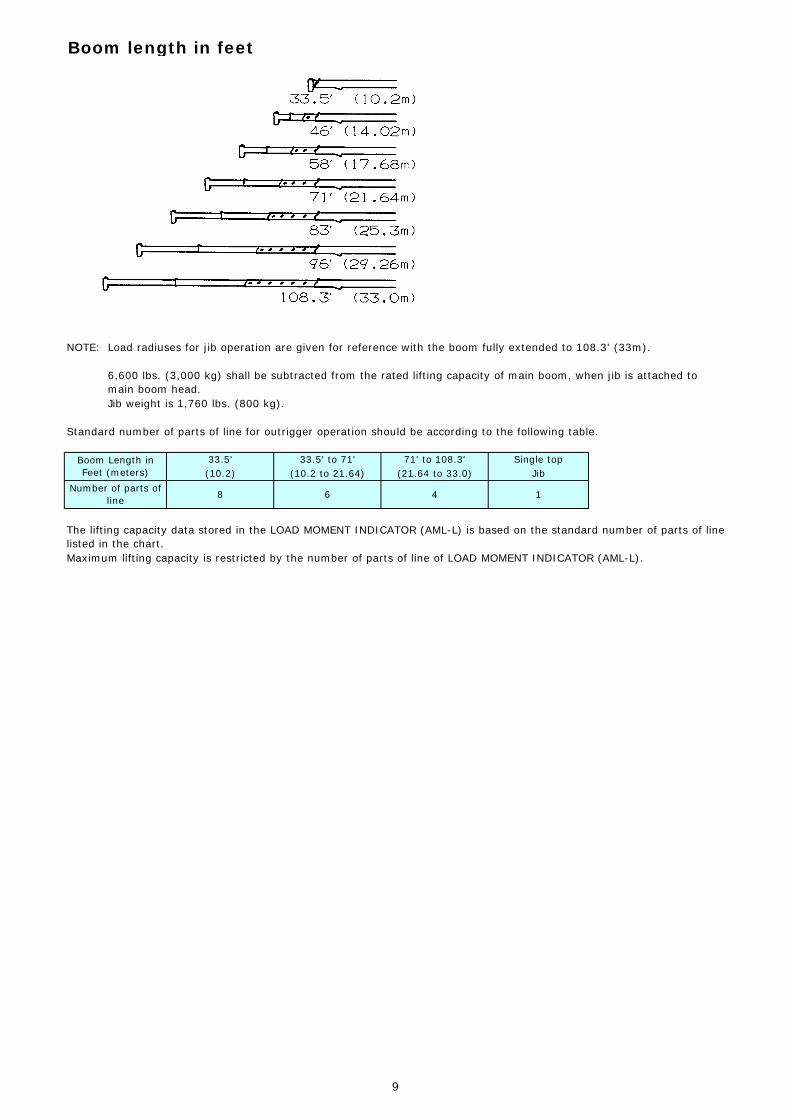
Boom length in feet
NOTE: Load radiuses for jib operation are given for reference with the boom fully extended to 108.3' (33m).
Jib weight is 1,760 lbs. (800 kg).
Standard number of parts of line for outrigger operation should be according to the following table.
Maximum lifting capacity is restricted by the number of parts of line of LOAD MOMENT INDICATOR (AML-L).
The lifting capacity data stored in the LOAD MOMENT INDICATOR (AML-L) is based on the standard number of parts of linelisted in the chart.
Boom Length inFeet (meters)
Number of parts ofline
71' to 108.3'(21.64 to 33.0)
4 18 6
6,600 lbs. (3,000 kg) shall be subtracted from the rated lifting capacity of main boom, when jib is attached tomain boom head.
Single topJib
33.5'(10.2)
33.5' to 71'(10.2 to 21.64)
9
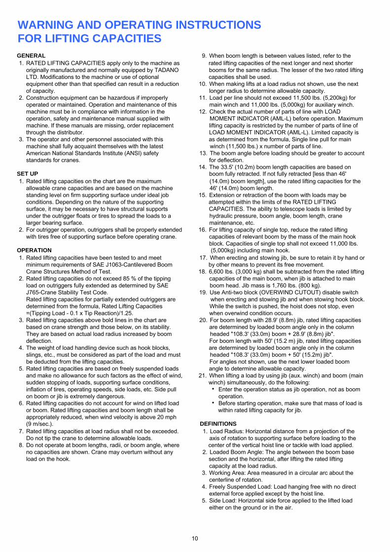
WARNING AND OPERATING INSTRUCTIONSFOR LIFTING CAPACITIESGENERAL 9. When boom length is between values listed, refer to the1. RATED LIFTING CAPACITIES apply only to the machine as rated lifting capacities of the next longer and next shorter
originally manufactured and normally equipped by TADANO booms for the same radius. The lesser of the two rated liftingLTD. Modifications to the machine or use of optional capacities shall be used.equipment other than that specified can result in a reduction 10. When making lifts at a load radius not shown, use the nextof capacity. longer radius to determine allowable capacity.
2. Construction equipment can be hazardous if improperly 11. Load per line should not exceed 11,500 lbs. (5,200kg) foroperated or maintained. Operation and maintenance of this main winch and 11,000 lbs. (5,000kg) for auxiliary winch.machine must be in compliance with information in the 12. Check the actual number of parts of line with LOADoperation, safety and maintenance manual supplied with MOMENT INDICATOR (AML-L) before operation. Maximummachine. If these manuals are missing, order replacement lifting capacity is restricted by the number of parts of line ofthrough the distributor. LOAD MOMENT INDICATOR (AML-L). Limited capacity is
3. The operator and other personnel associated with this as determined from the formula, Single line pull for mainmachine shall fully acquaint themselves with the latest winch (11,500 lbs.) x number of parts of line.American National Standards Institute (ANSI) safety 13. The boom angle before loading should be greater to accountstandards for cranes. for deflection.
14. The 33.5' (10.2m) boom length capacities are based onSET UP boom fully retracted. If not fully retracted [less than 46'1. Rated lifting capacities on the chart are the maximum (14.0m) boom length], use the rated lifting capacities for the
allowable crane capacities and are based on the machine 46' (14.0m) boom length.standing level on firm supporting surface under ideal job 15. Extension or retraction of the boom with loads may beconditions. Depending on the nature of the supporting attempted within the limits of the RATED LIFTINGsurface, it may be necessary to have structural supports CAPACITIES. The ability to telescope loads is limited byunder the outrigger floats or tires to spread the loads to a hydraulic pressure, boom angle, boom length, cranelarger bearing surface. maintenance, etc.
2. For outrigger operation, outriggers shall be properly extended 16. For lifting capacity of single top, reduce the rated liftingwith tires free of supporting surface before operating crane. capacities of relevant boom by the mass of the main hook
block. Capacities of single top shall not exceed 11,000 lbs.OPERATION (5,000kg) including main hook.1. Rated lifting capacities have been tested to and meet 17. When erecting and stowing jib, be sure to retain it by hand or
minimum requirements of SAE J1063-Cantilevered Boom by other means to prevent its free movement.Crane Structures Method of Test. 18. 6,600 lbs. (3,000 kg) shall be subtracted from the rated lifting
2. Rated lifting capacities do not exceed 85 % of the tipping capacities of the main boom, when jib is attached to mainload on outriggers fully extended as determined by SAE boom head. Jib mass is 1,760 lbs. (800 kg).J765-Crane Stability Test Code. 19. Use Anti-two block (OVERWIND CUTOUT) disable switchRated lifting capacities for partially extended outriggers are when erecting and stowing jib and when stowing hook block.determined from the formula, Rated Lifting Capacities While the switch is pushed, the hoist does not stop, even=(Tipping Load - 0.1 x Tip Reaction)/1.25. when overwind condition occurs.
3. Rated lifting capacities above bold lines in the chart are 20. For boom length with 28.9' (8.8m) jib, rated lifting capacitiesbased on crane strength and those below, on its stability. are determined by loaded boom angle only in the columnThey are based on actual load radius increased by boom headed "108.3' (33.0m) boom + 28.9' (8.8m) jib". deflection. For boom length with 50' (15.2 m) jib, rated lifting capacities
4. The weight of load handling device such as hook blocks, are determined by loaded boom angle only in the columnslings, etc., must be considered as part of the load and must headed "108.3' (33.0m) boom + 50' (15.2m) jib". be deducted from the lifting capacities. For angles not shown, use the next lower loaded boom
5. Rated lifting capacities are based on freely suspended loads angle to determine allowable capacity. and make no allowance for such factors as the effect of wind, 21. When lifting a load by using jib (aux. winch) and boom (mainsudden stopping of loads, supporting surface conditions, winch) simultaneously, do the following:inflation of tires, operating speeds, side loads, etc. Side pull Enter the operation status as jib operation, not as boomon boom or jib is extremely dangerous. operation.
6. Rated lifting capacities do not account for wind on lifted load Before starting operation, make sure that mass of load isor boom. Rated lifting capacities and boom length shall be within rated lifting capacity for jib.appropriately reduced, when wind velocity is above 20 mph(9 m/sec.). DEFINITIONS
7. Rated lifting capacities at load radius shall not be exceeded. 1. Load Radius: Horizontal distance from a projection of theDo not tip the crane to determine allowable loads. axis of rotation to supporting surface before loading to the
8. Do not operate at boom lengths, radii, or boom angle, where center of the vertical hoist line or tackle with load applied.no capacities are shown. Crane may overturn without any 2. Loaded Boom Angle: The angle between the boom baseload on the hook. section and the horizontal, after lifting the rated lifting
capacity at the load radius.3. Working Area: Area measured in a circular arc about the
centerline of rotation.4. Freely Suspended Load: Load hanging free with no direct
external force applied except by the hoist line.5. Side Load: Horizontal side force applied to the lifted load
either on the ground or in the air.
10
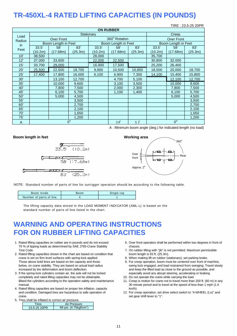
TR-450XL-4 RATED LIFTING CAPACITIES (IN POUNDS)
A : Minimum boom angle (deg.) for indicated length (no load)
Boom length in feet Working area
Standard number of parts of line for outrigger operation should be according to the following table.
WARNING AND OPERATING INSTRUCTIONSFOR ON RUBBER LIFTING CAPACITIES1. Rated lifting capacities on rubber are in pounds and do not exceed 6. Over front operation shall be performed within two degrees in front of
75 % of tipping loads as determined by SAE J765-Crane Stability chassis.Test Code. 7. On rubber lifting with "jib" is not permitted. Maximum permissible
2. Rated lifting capacities shown in the chart are based on condition that boom length is 83 ft. (25.3m).crane is set on firm level surfaces with spring-lock applied. 8. When making lift on rubber (stationary), set parking brake.Those above bold lines are based on tire capacity and those 9. For creep operation, boom must be centered over front of machine,below, on crane stability. They are based on actual load radius swing lock engaged, and load restrained from swinging. Travel slowlyincreased by tire deformation and boom deflection. and keep the lifted load as close to the ground as possible, and
3. If the spring-lock cylinders contain air, the axle will not be locked especially avoid any abrupt steering, accelerating or braking.completely and rated lifting capacities may not be obtainable. 10. Do not operate the crane while carrying the load.Bleed the cylinders according to the operation safety and maintenance 11. Creep is motion for crane not to travel more than 200 ft. (60 m) in anymanual. 30 minute period and to travel at the speed of less than 1 mph (1.6
4. Rated lifting capacities are based on proper tire inflation, capacity km/h).and condition. Damaged tires are hazardous to safe operation of 12. For creep operation, set drive select switch to "4-WHEEL (Lo)" andcrane. set gear shift lever to "1".
5. Tires shall be inflated to correct air pressure.
1,6501,200
0o
TIRE : 23.5-25 20PR
58'(17.68m)
83'(25.3m)
58'(17.68m)
ON RUBBERCreep
Over Front
4,500
18,70015,80012,700
3,5002,7002,100
9,6007,5005,700
7,8006,1005,000
32,00026,40020,00015,40012,10010,000
35,70030,800
14,1007,3005,1003,500
25,20018,50010,800
22,50017,50010,5006,9004,7003,1002,000
6,100
9,6007,5005,700
17,800
28,000
Boom Length in Feet
Stationary360o Rotation
Boom Length in FeetOver Front
Boom Length in Feet
25,50017,400
33.5'(10.2m)
83'(25.3m)
22,00016,9009,9006,100
LoadRadius
inFeet
33.5'(10.2m)
58'(17.68m)
83'(25.3m)
33.5'(10.2m)
37,00033,700
1,200
2,700
4,5003,500
13,10010,000 7,800
2,100
29,00022,500
1,100
68 psi. (4.75kgf/cm2)
The lifting capacity data stored in the LOAD MOMENT INDICATOR (AML-L) is based on thestandard number of parts of line listed in the chart.
Tires
Number of parts of lineBoom
23.5-25 20PR
1
75'A 30o 51o0o
Boom mode
Air Pressure
10'
30' 12,70016,00018,700
38,50033,600
4
12'15'20'25'
35'
5,000
1,650
Single top
Overfront
NOTE:
Approx. 2o
50'1,4002,30040'
45'
65'70'
55'60'
Rear
360o
11
WARNING AND OPERATING INSTRUCTIONSFOR USING THE LOAD MOMENT INDICATOR (AML-L)1. When operating crane on outriggers: However, pay attention to the following :
h Before outrigger operation, spring-lock in the over-front (1) For stationary operation :or over-rear area of the boom. h The front capacities are attainable only when the over(Locking and releasing cannot be performed in other state.) front position symbol comes on. When the boom is
h Keep pressing the switch to the "LOCK" side until the more than 2 degrees from centered over front ofspring lock confirmation lamp changes from flashing to chassis, 360o capacities are in effect.lighting, and lower the body to the full. h When a load is lifted in the front position and then(Outrigger operation and crane operation cannot be swung to the side area, make sure the value of theperformed without spring-locking.) LOAD MOMENT INDICATOR (AML-L) is below the
h Set P.T.O. switch to "ON". 360o lifting capacity.h Press the outrigger mode select key to register for the (2) For creep operation :
outrigger operation. Press the set key, then the h The creep capacities are attainable only when boomoutrigger mode indicative symbol changes from is in the straight forward position of chassis and theflickering to lighting. over front position symbol is on. If boom is not in the
h Press the boom mode select key to register the boom straight forward position of chassis, never lift load.mode, then the boom mode indicative symbol changes 3. A swing dose not automatically stop even if the cranefrom lighting to flickering. Each time the boom mode becomes overloaded.select key is pressed, the mode changes. Press the set 4. During crane operation, make sure that the displays onkey to select the status that corresponds to the actual front panel are in accordance with actual operatingstate of the boom, then the boom mode indicative conditions.symbol changes from flickering to lighting. 5. The displayed values of LOAD MOMENT INDICATOR
h When erecting and stowing jib, select the status of jib (AML-L) are based on freely suspended loads andset (jib state indicative symbol flicker). make no allowance for such factors as the effect of
2. When operating crane on rubber: wind, sudden stopping of loads, supporting surfaceh spring-lock in the over-front or over-rear area of the boom. conditions, inflation of tire, operating speed, side loads,
(Locking and releasing cannot be performed in other state.) etc. For safe operation, it is recommended whenh Keep pressing the switch to the "LOCK" side until the extending and lowering boom or swinging, lifting loads
spring lock confirmation lamp changes from flashing to shall be appropriately reduced.lighting, and lower the body to the full. 6. LOAD MOMENT INDICATOR (AML-L) is intended as(Crane operation cannot be performed without spring- an aid to the operator. Under no condition should it belocking.) relied upon to replace use of capacity charts and
h Set P.T.O. switch to "ON". operating instructions. Sole reliance upon LOADh Press the on-tire mode select key. The on-tire mode MOMENT INDICATOR (AML-L) aids in place of good
indicative symbol comes on. Each time the on-tire operating practice can cause an accident. The operatormode select key is pressed, the mode changes. must exercise caution to assure safety.Select the creep operation, the on-tire modeindicative symbol flicker.
h Press the boom mode select key to register the boommode.
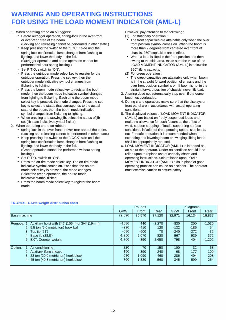
TR-450XL-4 Axle weight distribution chart
Base machine 35,570 37,120 32,971 16,134 16,837
Remove: 1. Auxiliary hoist with 345' (105m) of 3/4" (19mm) 440 -2,270 -830 200 -1,0302. 5.5 ton (5.0 metric ton) hook ball -410 120 -132 -186 543. Top jib (21') -600 70 -240 -272 324. Base jib (28.8') -2,070 820 -567 -939 3725. EXT. Counter weight 890 -2,650 -798 404 -1,202
Option: 1. Air conditioning 70 150 100 32 682. Auxiliary lifting sheave 390 -240 68 177 -1093. 22 ton (20.0 metric ton) hook block 1,090 -460 286 494 -2084. 45 ton (40.8 metric ton) hook block 1,320 -560 345 599 -254
630760
-530-1,250-1,760
220
PoundsGVW Front
150
Rear
-1830
72,690
-290
KilogramsGVW Front Rear
12

MEMO
TADANO AMERICA CORPORATION4300 CAMPBELL ROAD, HOUSTON, TEXAS 77041-9116U.S.A.PHONE: (713) 895-9400 EXT.315FAX: (713) 895-0352http://www.tadano-cranes.com/
Form No. TDN-GR-450XL-1-00101/US-01
13