trabajo 1 - upmwikifab.dimf.etsii.upm.es/wikifab/images/0/0f/trab0984_2012.pdfspecial machine for...
TRANSCRIPT

04 Chamfering
Special machine for chamfering pipe ends
1 Clamping cylinder2 Machine frame3 Machined workpiece4 Output roller conveyor5 Distributor6 Linear unit7 Roller conveyor magazine8 Pneumatic cylinder9 Insertion arm
10 Rotary drive11 Ejector12 Cutter head13 Electrical motor14 Spindle unit15 Stop16 Hydraulic cushioning
cylinder
2 Examples of pneumatic applications18
Functional sequence
1
2
3
4
5
6
7
8
9
10
11
12 13
14
15 16
17
Pipe sections are frequently required in random lengths and with chamferedends. The working units at each end of this special machine can be adjusted fordifferent workpiece lengths. The handling system used to insert and remove theworkpieces can be of a relatively simple design using pneumatic actuators. Inthe example shown, the workpieces are taken from a roller conveyor magazineand output to another roller conveyor magazine after machining. The workpiecesare clamped during machining; i.e. the tool executes the necessary motion. Thefeed motion of the slides can be made smoother if a hydraulic cushioningcylinder is connected in parallel with the working motion.
Suitable components: Linear unit SLT... or DFM... or DGPL-...-HD...Pneumatic single pilot valves VL...Semi-rotary drive DSR... Proximity switch SME... Hydraulic cushioning cylinder YDR...Mounting flange YSRF... Short stroke cylinder ADVU... Round cylinder DSEU...Mounting accessories
Trabajo 1
Instrumentación en Ingeniería Mecánica 2012

2 Examples of pneumatic applications34
Functional sequence
1
2
32
2
4
2
5
6
7
Certain workpieces tend to deform easily during processing and clamping. In theinterests of accuracy and to prevent deformity, these must be fitted with atemporary clamp sleeve to allow further processing. This is achieved by usingthe system shown above, which is partially automated. The clamp sleeves arefirst placed into a carrier by hand. The workpiece is then moved into the clam-ping position against the stop of the more powerful right-hand cylinder. This isfollowed by longitudinal pressing. After this, the stop cylinder retracts again,allowing the feed cylinder in a second action to push the finished workpieceonto the outward transfer conveyor belt. The clamp sleeves must be removedagain after processing has been completed. The workpieces are moved by handfrom the conveyors to the side setdown area.
Suitable components: Flat cylinder DZH...Mounting accessories Twin cylinder ADVUT...Safety start block for two-handed operation Pneumatic single pilot valve VL...Proximity switch SM... Fittings Standard cylinder DNC....Standard cylinder DNC-Q...Foot mounting HNG...
20 Press-fitting
Press-fitting clamp sleeves
1 Basic workpiece2 Pneumatic cylinder3 Clamp sleeve (workpiece
to be fitted)4 Support table5 Setdown area for finished
workpieces6 Conveyor chain drive7 Motor for conveyor
Trabajo 2
Instrumentación en Ingeniería Mecánica 2012

2 Examples of pneumatic applications 37
Functional sequence
1
2
3
4
5
6
7 5 8
9
10
11
12
The example shows the feed to a deburring press. The handling device picks upthe oriented castings from the conveyor using a twin-jaw gripper and positionsthem one at a time over the aperture plate and under the plunger. After debur-ring, the workpieces are fed by gravitational force into a collecting bin. Theswivel arm is equipped with a counterweight to prevent eccentric loads whichwould lead to excess guide wear. The end positions are equipped with adjust-able hydraulic cushioning cylinders. This motion sequence could, of course, alsobe achieved by using other configurations of pneumatic drives, such as a multi-axis handling devices with Cartesian coordinates using linear axes.
Suitable components: Rotary drive DRQD... and adapter plate Parallel gripper HGP... Proximity switch SM...Pneumatic single pilot valve VL... or valve terminal CP...Drive unit DFM... or SLT...Mounting accessories Fittings
23 Deburring
Deburring castings
1 Press2 Deburring plunger3 Aperture plate4 Gripper5 Deburred workpiece
(casting)6 Output chute7 Conveyor belt8 Stop9 Counterweight
10 Swivel unit11 Lifting slide12 Mounting bracket
37
Trabajo 3
Instrumentación en Ingeniería Mecánica 2012
2 Examples of pneumatic applications 39
Functional sequence
1
2
a b
3
4
5
6
78
9
10
11
6
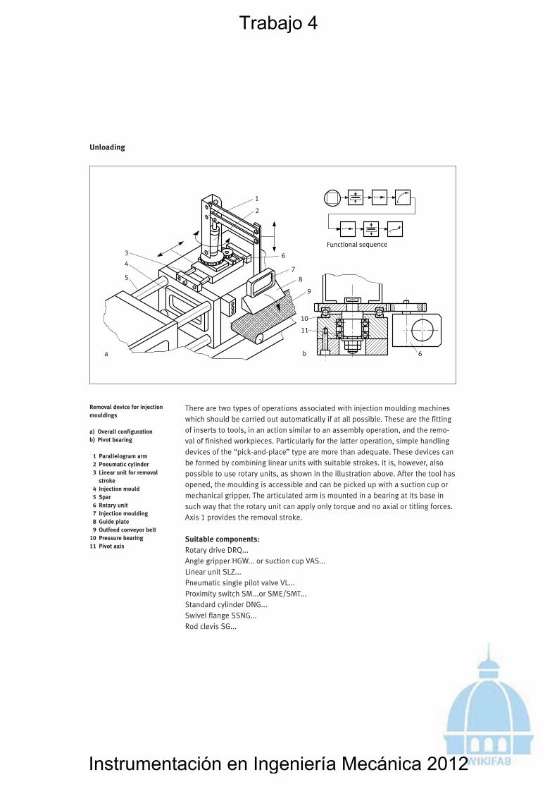
There are two types of operations associated with injection moulding machineswhich should be carried out automatically if at all possible. These are the fittingof inserts to tools, in an action similar to an assembly operation, and the remo-val of finished workpieces. Particularly for the latter operation, simple handlingdevices of the “pick-and-place” type are more than adequate. These devices canbe formed by combining linear units with suitable strokes. It is, however, alsopossible to use rotary units, as shown in the illustration above. After the tool hasopened, the moulding is accessible and can be picked up with a suction cup ormechanical gripper. The articulated arm is mounted in a bearing at its base insuch way that the rotary unit can apply only torque and no axial or titling forces.Axis 1 provides the removal stroke.
Suitable components: Rotary drive DRQ... Angle gripper HGW... or suction cup VAS... Linear unit SLZ... Pneumatic single pilot valve VL... Proximity switch SM...or SME/SMT... Standard cylinder DNG... Swivel flange SSNG... Rod clevis SG...
25 Unloading
Removal device for injectionmouldings
a) Overall configurationb) Pivot bearing
1 Parallelogram arm2 Pneumatic cylinder3 Linear unit for removal
stroke4 Injection mould5 Spar6 Rotary unit7 Injection moulding8 Guide plate9 Outfeed conveyor belt
10 Pressure bearing11 Pivot axis
39
Trabajo 4
Instrumentación en Ingeniería Mecánica 2012

2 Examples of pneumatic applications56
Functional sequence
1
12
3
4 5 6
7
88
9
10
11 12
13
In the assembly of bushes using a longitudinal pressing action, it is very impor-tant that the two components to be assembled are in precise coaxial alignmentto each other. To achieve this in the example shown, a counterholding clampsleeve is first applied to the basic component, and a centring mandrel is thenrun through this component to the bush located on the other side. This opera-tion produces axial alignment to within very close tolerances. The bush is thusintroduced into the bore during the press-fitting operation. All motions are pro-duced by pneumatic actuators. These motions include the separation of thebushes from the stack magazine and the clamping of the basic component bythe two linear units. These operations are followed by the actual assembly of thetwo workpieces, during which the centring mandrel is pushed back, finallyreturning to its initial position. The clamping of the basic component ensuresthat no impermissible forces act on the transfer system or workpiece carrier. Atthe end of the operation, the two linear units return to their initial position,allowing the workpiece carrier to be moved on without obstruction.
Suitable components: Standard cylinder ESN... Round cylinder DSW... Guide unit DFM... Pneumatic single pilot valve... Proximity switch SM... Fittings, Mounting accessories
42 Assembly
Assembly station for bearingbushes
1 Magazine2 Joining part (bearing
bush)3 Basic assembly
component4 Centring mandrel cylinder5 Counterholding and clam-
ping sleeve6 Tapered centring
attachment7 Distributor drive cylinder8 Linear unit9 V-support for joining part
10 Distributor pin11 Clamp claw for basic
component12 Workpiece carrier13 Transfer system roller
conveyor
Trabajo 5
Instrumentación en Ingeniería Mecánica 2012

2 Examples of pneumatic applications58
Functional sequence
1
2
3
4
5
6
7
8 910
11
Shaft circlips are often used to secure components in mechanical-engineeringdevices. Various mechanisms have been developed to allow the fitting of thesecirclips. In the above example, circlips are separated out of a magazine by a slideand brought to a spreading station. Once each circlip has been spread, it is fixedinto place in the robotised holding device by a tapered piece. When this comesinto contact with the assembly module, the tapered piece retracts and the circlipnow snaps into place in the slot at the end of the shaft. It is important that thecirclip should not be stretched excessively during this operation, which couldlead to plastic deformation. The opening of the gripper fingers is thus duly con-trolled by a spreading-force regulator. The radial gripper at the same time pre-cisely defines the axis centre to which the handling device is aligned. The fittinghead can also be mounted on a pneumatic handling device.
Suitable components: Three-point gripper HGD... Compact cylinder ADVUL... Pressure regulator LR... Pneumatic single pilot valve...Standard cylinder ESN... or slide SLG... Proximity switch SM... Fittings Mounting accessories
44 Assembly
Assembly device to fit circlipsto shafts
1 Circlip magazine2 Fitting head3 Tapered piece4 Feed slide5 Three-point gripper6 Lifting plate7 Spreading-force regulator8 Circlip9 Gripper finger
10 Joining part11 Basic assembly
component
Trabajo 6
Instrumentación en Ingeniería Mecánica 2012
2 Examples of pneumatic applications 59
Functional sequence1
234
5
6
7
8
9
10
13
11
12
8
17
1018
16Clearance
14
15
12
19
a b
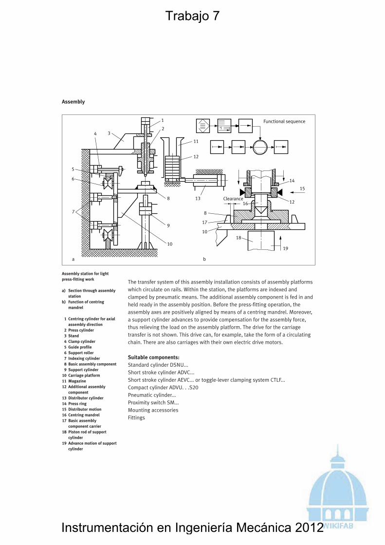
45 Assembly
Assembly station for lightpress-fitting work
a) Section through assembly station
b) Function of centring mandrel
1 Centring cylinder for axial assembly direction
2 Press cylinder3 Stand4 Clamp cylinder5 Guide profile6 Support roller7 Indexing cylinder8 Basic assembly component9 Support cylinder
10 Carriage platform11 Magazine12 Additional assembly
component13 Distributor cylinder14 Press ring15 Distributor motion16 Centring mandrel 17 Basic assembly
component carrier18 Piston rod of support
cylinder19 Advance motion of support
cylinder
The transfer system of this assembly installation consists of assembly platformswhich circulate on rails. Within the station, the platforms are indexed andclamped by pneumatic means. The additional assembly component is fed in andheld ready in the assembly position. Before the press-fitting operation, theassembly axes are positively aligned by means of a centring mandrel. Moreover,a support cylinder advances to provide compensation for the assembly force,thus relieving the load on the assembly platform. The drive for the carriagetransfer is not shown. This drive can, for example, take the form of a circulatingchain. There are also carriages with their own electric drive motors.
Suitable components: Standard cylinder DSNU...Short stroke cylinder ADVC...Short stroke cylinder AEVC... or toggle-lever clamping system CTLF... Compact cylinder ADVU. . .S20 Pneumatic cylinder... Proximity switch SM... Mounting accessoriesFittings
59
Trabajo 7
Instrumentación en Ingeniería Mecánica 2012
2 Examples of pneumatic applications72
Functional sequence
1
2 3 4 5
6
7
8
9
10
11
12
13
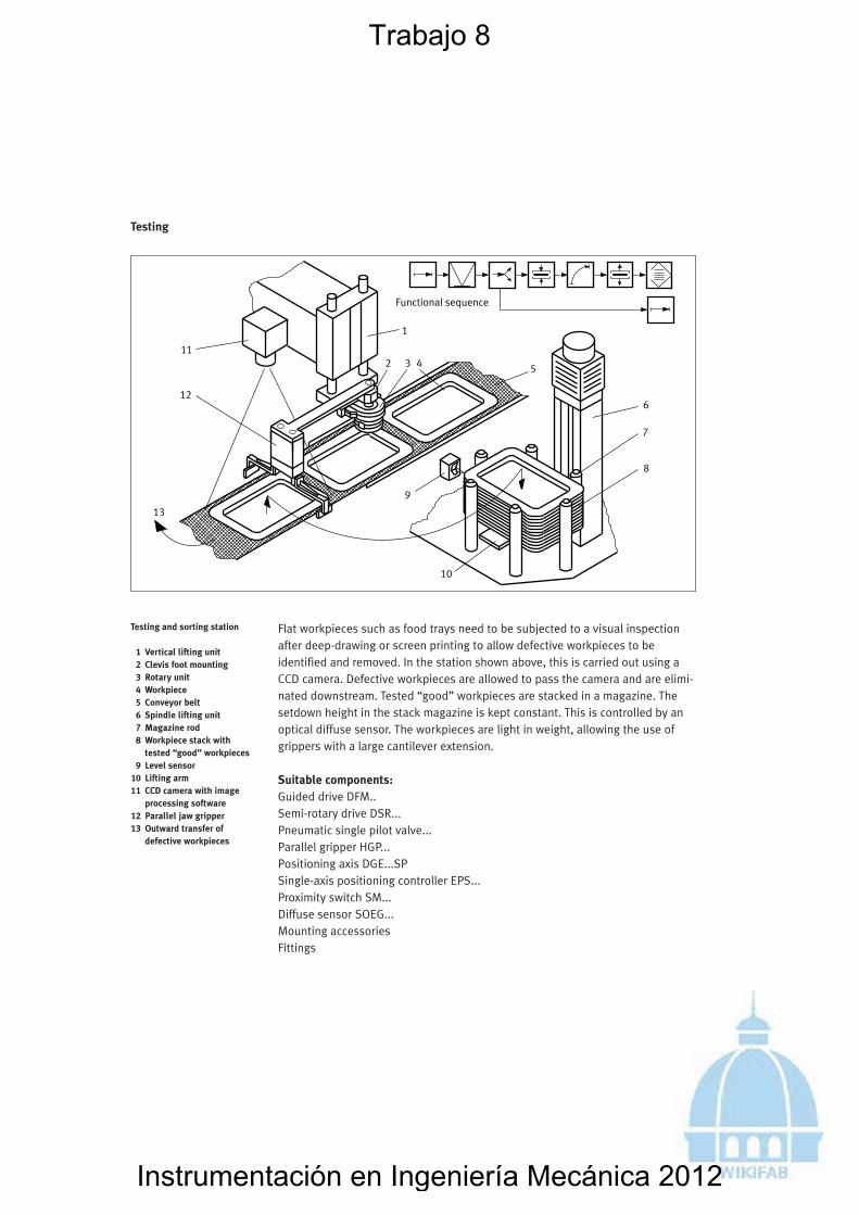
Flat workpieces such as food trays need to be subjected to a visual inspectionafter deep-drawing or screen printing to allow defective workpieces to beidentified and removed. In the station shown above, this is carried out using aCCD camera. Defective workpieces are allowed to pass the camera and are elimi-nated downstream. Tested “good” workpieces are stacked in a magazine. Thesetdown height in the stack magazine is kept constant. This is controlled by anoptical diffuse sensor. The workpieces are light in weight, allowing the use ofgrippers with a large cantilever extension.
Suitable components: Guided drive DFM.. Semi-rotary drive DSR... Pneumatic single pilot valve... Parallel gripper HGP... Positioning axis DGE...SPSingle-axis positioning controller EPS... Proximity switch SM... Diffuse sensor SOEG... Mounting accessories Fittings
58 Testing
Testing and sorting station
1 Vertical lifting unit2 Clevis foot mounting3 Rotary unit4 Workpiece5 Conveyor belt6 Spindle lifting unit7 Magazine rod8 Workpiece stack with
tested “good” workpieces9 Level sensor
10 Lifting arm11 CCD camera with image
processing software12 Parallel jaw gripper13 Outward transfer of
defective workpieces
Trabajo 8
Instrumentación en Ingeniería Mecánica 2012
2 Examples of pneumatic applications 93
Functional sequence
1
2
3
4
5
6
7
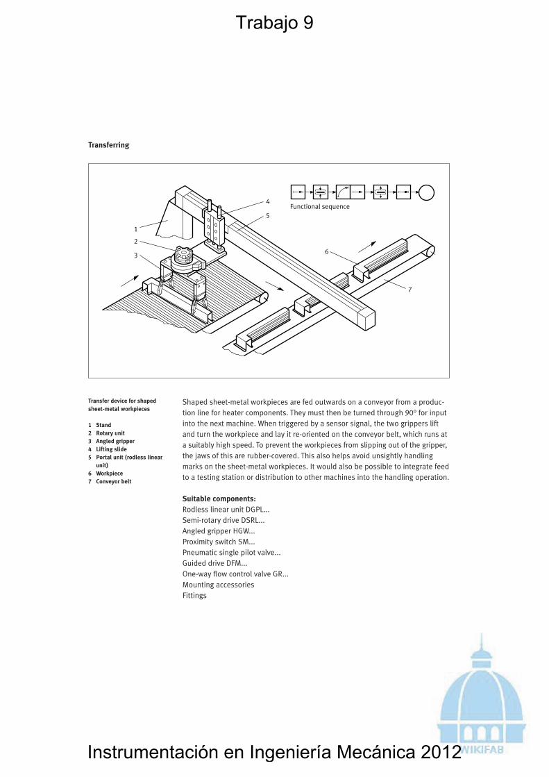
Shaped sheet-metal workpieces are fed outwards on a conveyor from a produc-tion line for heater components. They must then be turned through 90° for inputinto the next machine. When triggered by a sensor signal, the two grippers liftand turn the workpiece and lay it re-oriented on the conveyor belt, which runs ata suitably high speed. To prevent the workpieces from slipping out of the gripper,the jaws of this are rubber-covered. This also helps avoid unsightly handlingmarks on the sheet-metal workpieces. It would also be possible to integrate feedto a testing station or distribution to other machines into the handling operation.
Suitable components:Rodless linear unit DGPL...Semi-rotary drive DSRL...Angled gripper HGW...Proximity switch SM...Pneumatic single pilot valve...Guided drive DFM... One-way flow control valve GR...Mounting accessoriesFittings
79 Transferring
Transfer device for shapedsheet-metal workpieces
1 Stand2 Rotary unit3 Angled gripper4 Lifting slide5 Portal unit (rodless linear
unit)6 Workpiece7 Conveyor belt
93
Trabajo 9
Instrumentación en Ingeniería Mecánica 2012

2 Examples of pneumatic applications 95
Functional sequence12
3
45
6
3
7
3 8 89
10
9a b
The transfer of workpieces from one system section to another is often combinedwith the formation of new setdown patterns, for example as a necessary pre-paration for packing. The illustration shows how bottles pass through work-stations in groups of 3 and are then, still in these groups, pushed onto a lateralaccumulation zone. The lateral ejection operation is started when the sensorconfirms that a complete group of 3 bottles has arrived. It may be possible toeliminate the need for a stop slide if the ejector slide is also able to provide thisfunction (Fig. b). A further design simplification can be achieved by using drivecylinders with non-rotating piston rods or oval pistons.
Suitable components:Standard cylinder ESN... or flat cylinder DZF...Compact cylinder AEVU... or AEVULQ...Proximity switch SM...One-way flow control valve GR...Diffuse sensor SOEG...Mounting accessoriesFittings
81 Re-positioning
Bottle re-positioning device
a) Overall view of installation
b) Variant using a non-rotating piston rod
1 Filling station2 Beverage bottle3 Stop-slide cylinder4 Conveyor belt5 Lateral accumulation zone6 Multiple closure device7 Sensor8 Pneumatic cylinder9 Ejector slide
10 Protection against torsion
95
Trabajo 10
Instrumentación en Ingeniería Mecánica 2012
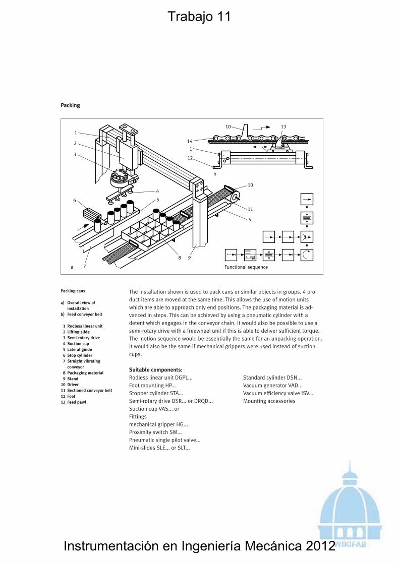
The installation shown is used to pack cans or similar objects in groups. 4 pro-duct items are moved at the same time. This allows the use of motion unitswhich are able to approach only end positions. The packaging material is ad-vanced in steps. This can be achieved by using a pneumatic cylinder with adetent which engages in the conveyor chain. It would also be possible to use asemi-rotary drive with a freewheel unit if this is able to deliver sufficient torque.The motion sequence would be essentially the same for an unpacking operation.It would also be the same if mechanical grippers were used instead of suctioncups.
Suitable components:Rodless linear unit DGPL... Standard cylinder DSN...Foot mounting HP... Vacuum generator VAD...Stopper cylinder STA... Vacuum efficiency valve ISV...Semi-rotary drive DSR... or DRQD... Mounting accessoriesSuction cup VAS... orFittingsmechanical gripper HG...Proximity switch SM...Pneumatic single pilot valve...Mini-slides SLE... or SLT...
2 Examples of pneumatic applications100
Functional sequencea
b
1
1
2
3
4
56
7
8 9
10
11
5
1310
14
12
85 Packing
Packing cans
a) Overall view of installation
b) Feed conveyor belt
1 Rodless linear unit2 Lifting slide3 Semi-rotary drive4 Suction cup5 Lateral guide6 Stop cylinder7 Straight vibrating
conveyor8 Packaging material9 Stand
10 Driver11 Sectioned conveyor belt12 Foot13 Feed pawl
Trabajo 11
Instrumentación en Ingeniería Mecánica 2012

2 Examples of pneumatic applications
The illustration shows a solution for the feed and removal of round parts on anautomatic lathe. A v-shaped height adjustable carrier accepts a blank workpiecefrom the magazine and lifts this to the centre of the chuck axis. In this position,it is pushed into the chuck by a ram (not shown). After machining, the finishedworkpiece falls into a tray which then tips towards an outlet chute. The entiredevice is mounted on a base plate and can be attached to prepared areas onmachine tools. During machining, the workpiece-carrying components must beswivelled into a parking position out of the way of machining chips.
Suitable components:Standard cylinder ESN...Standard cylinder DNG...or DNC...Proximity switch SM...Pneumatic cylinderClevis foot mounting LBG...Rod eye SGS...One-way flow control valve GR...Trunnion support LNZ...Mounting accessoriesFittings
103
Functional sequence
1
2
3
45
6
7 8
9
10
11
12
3
13
88 Feeding
Magazine feed for an auto-matic lathe
1 Magazine for cylindrical workpieces
2 Workpiece (blank)3 Pneumatic cylinder4 Four-link mechanism
(double rocker)5 Outlet chute6 Finished workpiece7 Pneumatic cylinders for
feed function8 Collet chuck9 Tool slide
10 Feed device11 Removal device12 Articulated joint13 Angle lever
103
Trabajo 12
Instrumentación en Ingeniería Mecánica 2012
2 Examples of pneumatic applications
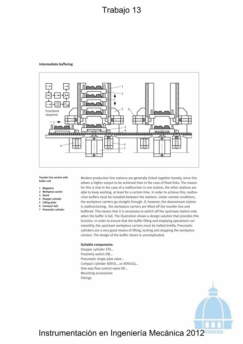
Modern production line stations are generally linked together loosely, since thisallows a higher output to be achieved than in the case of fixed links. The reasonfor this is that in the case of a malfunction in one station, the other stations areable to keep working, at least for a certain time. In order to achieve this, malfun-ction buffers must be installed between the stations. Under normal conditions,the workpiece carriers go straight through. If, however, the downstream stationis malfunctioning, the workpiece carriers are lifted off the transfer line andbuffered. This means that it is necessary to switch off the upstream station onlywhen the buffer is full. The illustration shows a design solution that provides thisfunction. In order to ensure that the buffer filling and emptying operations runsmoothly, the upstream workpiece carriers must be halted briefly. Pneumaticcylinders are a very good means of lifting, locking and stopping the workpiececarriers. The design of the buffer stores is uncomplicated.
Suitable components:Stopper cylinder STA...Proximity switch SM...Pneumatic single pilot valve...Compact cylinder ADVUL...or ADVULQ...One-way flow control valve GR...Mounting accessoriesFittings
113
Functionalsequence
1
2
3 4
56
47
4
98 Intermediate buffering
Transfer line section withbuffer unit
1 Magazine2 Workpiece carrier3 Stand4 Stopper cylinder5 Lifting plate6 Conveyor belt7 Pneumatic cylinder
113
Trabajo 13
Instrumentación en Ingeniería Mecánica 2012

Buffer stores have the task of decoupling pieces of production equipment fromeach other and thus providing loose linkage which results in better overallsystem performance in cases of individual machine malfunctions. The illustrationshows a buffer store which accepts bar material (for example, with diameters of10 to 30 mm and lengths of 150 to 600 mm) from a conveyor belt, stores thistemporarily and outputs to a machine tool on demand. All the necessary motionscan be produced using pneumatic components. The workpieces which arepushed off the roller conveyor pass to the inserter and are stored in the stackmagazine. On removal from this, the workpieces are separated by a rotary feeddevice and fed to the machine tool by a three-axis handling unit. The systemachieves a cycle time of around 5 seconds.
Suitable components:Compact cylinder AEVU...Standard cylinder DNC...Foot mounting HNC...Semi-rotary drive DSR...Linear unit DPZJ...Parallel gripper HGP...Proximity switch SM...Pneumatic single pilot valve...Mounting accessories and fittings
2 Examples of pneumatic applications114
Functional sequence
1
23
4
5 6 7
8
9
10
11
12
13
99 Intermediate buffering
Feeding and buffering of barworkpieces
1 Pusher cylinder2 Roller conveyor (linking
conveyor)3 Inserter4 Spring-loaded detent5 Feeder6 Rotary drive7 Output chute8 Rotary/linear unit9 Stack magazine
10 Linear unit11 Gripper12 Clamping device13 Machine tool
Trabajo 14
Instrumentación en Ingeniería Mecánica 2012