trabajos de fÍsica - famaf unc · trabajos de fÍsica nº 12/2010 electric instability-induced...
TRANSCRIPT

UNIVERSIDAD NACIONAL DE CÓRDOBA
FACULTAD DE MATEMÁTICA, ASTRONOMÍA Y FÍSICA ______________________________________________________________________
SERIE “A”
TRABAJOS DE FÍSICA
Nº 12/2010
Electric instability-induced hexagonal and cellular structures in the nematic state
L. E. Aguirre - A. P. Mammana - E. Anoardo
Editores: Ricardo C. Zamar–Miguel A. Chesta ____________________________________________________________
CIUDAD UNIVERSITARIA – 5000 CÓRDOBA
REPÚBLICA ARGENTINA

Electric instability-induced hexagonal and cellular structures in the nematic state
L. E. Aguirre1, A. P. Mammana2 and E. Anoardo1
1 - Facultad de Matemática, Astronomía y Física, Universidad Nacional de Córdoba, and IFEG – CONICET. Córdoba – Argentina.
2 - ABINFO. Campinas – Brazil.
An investigation of electrically-induced structures in the nematic phase has been made by using optical video microscopy. Cellular patterns and hexagonal structures were observed in electro-optical cells with gaps of 127µm and 250µm, in response to a combined AC/DC excitation voltage. It is found that a regular hexagonal pattern grows-up for a particularAC/DC ratio of 0.5. The frequency dependence of the AC threshold voltage and the critical wave number of the structure was analyzed. The role of surface flexoelectric interactions is discussed.
PACS: 42.70.Df, 61.30.Gd, 78.20.Jq, 83.80.Xz.
Keywords: nematic, hexagonal pattern, cellular pattern, electric field.

Introduction
It was recently observed that acoustic manipulation of the molecular order in
nematic 4-pentyl-4'-cyanobiphenyl (5CB) could strongly affect the proton spin-lattice relaxation dispersion [1]. It was suggested that three dimensional (3D) order structures developing in the sample volume could be responsible of this result. This lead us to think in the possibility that certain external perturbations could induce order structures in the bulk, as an extension of the phenomena that takes place in inhomogeneous Fredericksz’s transitions in glass cells (2D). For this reason, and considering the intrinsic technical difficulties in a direct analysis of bulk structures, we decided to work in glass cells with progressive increasing gaps, in order to switch from a 2D regime to a bulk regime, while preserving the applicability of optical methods.
Pattern formation of periodic structures in nematic liquid crystals following the
application of external fields has been deeply studied during the last 20 years. Magnetic, electric and acoustic fields were probed. Important differences can be attributed to each of these cases, although some common underlying features can be identified. For instance, charge injection effects and electro-hydrodynamic (EHD) instabilities are exclusive of the electric case. A plenty of publications deal with different patterns, particularly for cells excited with electric fields and filled with liquid crystals having different physical parameters. The vast majority of the reported studies were performed in thin glass-cells of the order or less than 50µm thickness. Although some effects are by the date clearly established, there are still unclear situations and irreconcilable interpretations in the literature. Theoretical descriptions are in general complex, thus ending in general with simplified models. In the rest of the paper we refer to the electric case.
EHD destabilization is the most commonly argued process, associated to the presence of charges within the liquid crystal in the cell. Charges may be generated by electrolytic separation [2], injection from the electrodes (Felici instability) [3] or due to the characteristic conductance anisotropy of the nematic media (Carr-Helfrich instability) [4]. Charge injection may be due to thermo-ionic emission [5]. The space charge is driven by the electric field thus inducing a convective flow, in analogy to the Bernard’s thermal convection in fluids. EHD instability is easily observable in nematic compounds having negative dielectric anisotropy ∆ε and positive conductivity anisotropy ∆σ, and less frequently, when ∆ε> 0 and ∆σ < 0 [6]. It has been rarely observed in liquid crystals having a large positive ∆ε with positive ∆σ, while several related features remain unclear for this case. Starting from planar order with a large positive ∆ε, the Fréedericksz transition takes place at low voltages. Therefore, before the set-up of the EHD instability, the cell becomes homeotropically ordered, thus preventing the Carr-Helfrich instability [7]. Under these conditions, the Felici instability manifests.
The flexoelectric effect represents the linear coupling between the electric field and
the liquid crystal distortion [8]. Alternatively, it is possible to define the “gradient flexoelectric effect” between an electric field gradient and the liquid crystal order [9]. It may have a dipolar or quadrupolar (mostly) character and becomes relevant mainly at time independent (DC) or low-frequency alternating (AC) fields. Although the

flexoelectric interaction is usually considered to be dominant close to the electrode surfaces [10], flexoelectric domains may also exist in the bulk [11,12]. While the dielectric interaction causing the Fréedericksz transition is not sensitive to the electric field polarity (quadratic in field), the linear flexoelectric, like other surface polarization processes, are field polarity-sensitive. This fact concludes with completely different situations in the middle bulky cell and close to the electrodes, especially in thick cells. Weak anchoring favors the flexo-polarization at surface boundaries [13]. Even the molecular structure and the interaction with the solid surface at the boundary plays a role in the surface polarization [14,15].
Under certain circumstances, it may happen that a static structure originates close to
the electrode surface. This scenario can be met when linear terms become relevant in response to polar surface instabilities under the action of a DC field (or low-frequency AC field or, a combination of DC and high-frequency AC). At high frequencies, the AC field does not contribute to the linear terms. Static structures may form if the electric field intensity is weak enough to avoid a relevant EHD process. With field increase, the EHD convective flow manifest, and the set-up of the resulting pattern may follow the already existing static “non-convective” structure, thus showing a similar optical texture [16].
In thick cells, reorientation-mediated flow can also contribute to destabilize the
molecular orientation. In such cases, a back-flow may follow the Fréedericksz transition, thus adding an additional hydrodynamic torque [17]. The hydrodynamic model for EHD instabilities in nematics, considering the Maxwell equations, elastic, viscous and electric torques and fluid flow, could successfully explain the cases where dielectric and conductivity anisotropies have contrary signs. For such cases, it was considered that the role of the flexoelectric term was minor, even in the conductive regime (low AC frequencies) [18]. However, it was found that the hydrodynamic theory cannot explain the EHD instability growing from planar order when ∆ε< 0 and ∆σ <0, unless the flexoelectric interaction is considered [19]. The theory also fails when ∆ε> 0 and ∆σ >0. For this last case, cellular patterns where recently observed at both planar and homeotropic orders [20]. EHD was claimed to be the dominant mechanism. With increasing voltage, the cellular structure turns into rolls. In contrast to these, the cellular pattern showed to be nearly frequency independent. The authors claim that the cellular structure originates at the center of the cell (20µm thickness), while the rolls do form at the electrode surfaces. The inclusion of flexoelectric interaction in the equations seemed to be insufficient to explain the patterns, particularly in the homeotropic case. A closed explanation of the observed patterns, specially the cellular structure, is still pending.
In this work we deal with electric excitation of electro-optical cells of different gaps
filled with a liquid crystal having both positive dielectric and conductive anisotropies. We progressively increase the gap of the cell with the purpose of examining the thickness dependence of the observed patterns, within a regime where the physical conditions that influence the nematic director at the surface electrodes are markedly different to those occurring at the center of the cell. The cell gap was still thin enough in order to observe the transmitted light by optical means. The main focus of this study concerns to the investigation of the combined action of AC and an offset DC excitation of the cell. As a salient characteristic of the obtained results, regular hexagonal patterns could be observed in cells of 127µm and 250µm. Experimental evidence suggests that the hexagonal structure is a consequence of the interaction of circularly expanding
reorientational fronts, originated at spatially-localized more or less equidistant centers formed at the electrode surface.
Experimental and results
The electro-optical cells were built using transparent glass electrodes prepared by
sputtering ITO (Indium Tin Oxide) on one side of the glass decks. Superficial treatment was done by rubbing a deposition of PVA (Polyvinyl alcohol, layer thickness of 0.3-0.6µm). Cells with gaps of 50, 127 and 250µm were prepared using calibrated kapton separators. After checking the gap by optical interferometry, cells were filled with 5CB. Cells with thinner gaps were filled by capillarity.
All experiments were done at 298K. The video microscopy set-up was based on an
Olympus BH2-SC microscope equipped with a RCA TC2014/X video camera. Video signals were digitized using an Encore ENLTV-FM PCI board, having a resolution of 720x576 at 30fps. Crossed polarizers were used to enhance the contrast of the images. The polarizer was placed in parallel to the initial alignment of the nematic director in the cell, while the analyzer was perpendicular. Electro-optical cells were powered with an Agilent 33220A function generator, with delivery voltages from 0Vpp to 20Vpp. A sinusoidal AC voltage of 50Hz was used in the experiments. For a pure AC voltage over a threshold value, a homogeneous Freedericksz transition takes place, turning the cell into a homeotropic state. This behavior was independent of the gap thickness.
A DC offset was added to the AC signal once the cell was in equilibrium (after a
Fréedericksz transition). The offset intensity was increased in steps of 0.5Vpp. No optical changes were detected in the cell up to a critical threshold value of the offset, corresponding to a ratio R≈0.5 between the AC and DC voltages. From now on, we mention AC voltage values for R≈0.5.
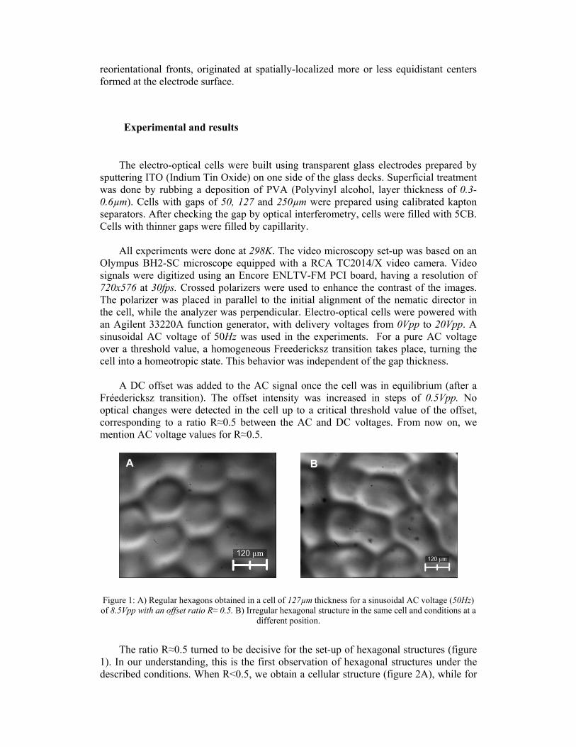
Figure 1: A) Regular hexagons obtained in a cell of 127µm thickness for a sinusoidal AC voltage (50Hz) of 8.5Vpp with an offset ratio R≈ 0.5. B) Irregular hexagonal structure in the same cell and conditions at a
different position.
The ratio R≈0.5 turned to be decisive for the set-up of hexagonal structures (figure
1). In our understanding, this is the first observation of hexagonal structures under the described conditions. When R<0.5, we obtain a cellular structure (figure 2A), while for
A B

R>0.5, a chaotic flowing state is reached (figure 2B). This result was independent of the sign of the offset voltage. The same equilibrium patterns follow the sudden application of the combined AC/DC voltage to a relaxed cell. It was experimentally verified that the individual action of the AC or DC voltages does not allow the formation of hexagonal structures, within the voltage ranges scanned in our experiments. The cellular structure has the same characteristic wavelength of the hexagonal pattern, and its formation process is similar. It should be stressed that once the structure sets-up reaching an equilibrium state, the positional order is preserved. Flow can be clearly observed is the chaotic state, but not during the formation of the cellular pattern. If the AC or the DC voltage is further increased (at R<0.5), the cellular domains tend to fusion into roll-like domains (Figure 4A).
Figure 2: A) Cellular pattern obtained in cells of 127µm thickness for an AC/DC ratio below 0.5. B)
Flowing structure obtained for an AC/DC ratio above 0.5 (same cell).
Figure 3 resumes a phase diagram for the cell of 127µm.
Figure 3: phase diagram for the cell of 127µm. The shadowed region indicates the transition region
between structures.
A B

Now we describe in detail the set-up process of the hexagonal pattern. After application of the combined AC/DC voltage with R≈0.5, a Fréedericksz transition takes place. Slowly but immediately after the cell has switched to a homeotropic state, light spots evolving to Maltese crosses can be observed (Figure 4B). Repeating the experiment after erasing the memory of the system (by heating the cell up to the clearing point), it was possible to verify that the position at which the bright spots starts to form are completely random. A circularly propagating instability start to develop from the spots/crosses until they interact between each other forming a cellular pattern in a time of about 3 minutes. This pattern evolves to a stable hexagonal structure after a time of the order of 17minutes. A similar result is obtained in the cell of 250µm. After switching-off the electric field, the cell becomes dark in a time of 40s. A sequence of pictures of the time evolution of the process was added as auxiliary material, see http://www.famaf.unc.edu.ar/publicaciones/documents/serie_a/secuencia.pdf .
Figure 4: A) Fusion of cellular domains into roll-like domains after increasing the DC voltage (R<0.5).
B) Bright spots/crosses following the Fréedericksz transition in the cell of 127µm.
Figure 5 shows that the centers of the hexagonal structures coincide with bright
spots, particularly when the microscope focal plane is set close to the surface boundary region. However, as soon as the focus is shifted inwards in the cell, the brilliant centers disappear, thus indicating that the nematic director distortions originating the spots/crosses are mainly located close to the surface.
Figure 5: A) Hexagonal formation at the electrode surface in the cell of 127µm. The in-depth resolution is 5µm. Bright spots are clearly located at the center of the hexagons. B) Same structure but with the focus
A B
A B

of the microscope shifted about 30µm inwards in the cell. The absence of the bright spots suggests that the set-up process of the structure takes place at the electrode surface boundary.
After removal of the electric perturbation the cell turns back to the homogeneous
state. Nevertheless, if the electric excitation is reapplied within a given time delay, the hexagonal pattern is recovered in a few seconds. The relaxation time of the hexagonal structure was measured by increasing the time delay between the removal and reapplication of the electric perturbation. When this delay gets longer than the relaxation time of the structure, the cell shows a new transition to a homogeneous state. Measured times were 15 and 17 minutes for the cells of 127 and 250µm respectively. For longer times, the whole process starts from the beginning: Fréedericksz transition followed by the evolution to the hexagonal structure.
No regular hexagonal structures were observed in the cell of 50µm, only the cellular pattern. A hexagonal radius of 100µm was measured for the 127µm cell while a value of 200µm was measured for the thicker cell of 250µm. Threshold values of the AC perturbation were 5Vpp for 127µm gap and 8Vpp for 250µm. Once the hexagonal pattern was established, the stability of the structure was proved up to 24hs. That is, after leaving the cell powered with both AC and DC offset for a time of several hours, the pattern was unchanged. The relaxation time of the structure showed to be independent of the time the cell was powered.
Both the threshold value of the AC/DC field (with R≈0.5) and the critical wave number q=2d/λ (where d is the cell thickness and λ the pattern associated wavelength) remain almost frequency independent at frequencies higher than 10Hz (figures 5 and 6). In addition, it was observed that the threshold increases with the cell thickness, although the dependence was not linear.
Figure 6: Threshold voltage in the cell of 127µm as a function of the AC frequency.

Figure 7: Frequency dependence of the critical wave number q in the cell of 127µm.
Discussion Following the Fréedericksz transition, when the electric field is high enough, a
strong splay-bend deformation occurs close to the surface, while a full homeotropic alignment takes place at the center of the cell. This condition is stable as far as the electric voltage applied to the cell is maintained.
The fact that the threshold voltage depends on the cell thickness, although not in a
linear way, suggest that a field-effect is present. We assume that charge accumulation within a thickness of the order of the Debye screening length (∼0,5µm) happens. However, with the experimental information we have, we cannot speculate about the origin of it (electrolytic separation, thermoionic emission, etc.). The PVA shell may partially prevent the injection of ions from the electrodes, being however this blocking process not completely efficient. Due to surface imperfections and topological defects, the presence of undesirable dust particles and/or other elements dissolved in the liquid crystal and, the nematic director distortions close to the surface, the electric field in this region is not uniform. The electric field gradient interacts with the surface charges, which in turn interacts themselves, thus generating a nonuniform charge distribution along the surface. In addition, at the surface, the nematic director symmetry breaks out and a macroscopic surface polarization develops [15]. The relative contribution to this process due to the AC field is minor. At low DC voltages, surface polarization and charge distribution may be effective without the establishment of a relevant electric current across the cell, particularly at the lowest temperature of the mesophase [5]. No structures were observed in identical cells without the PVA surface treatment at the same conditions. This fact reveals the critical role of the surface manipulation in the resulting patterns.
Following the described scenario, strong local distortions of the molecular
orientations will occur at surface positions where the electric field gradients are strong.

In consequence, localized flexoelectric energy builds-up at these surface positions [13,21]. Due to the fact that the dielectric response of the cell (Fréedericksz transition, a few seconds) is much faster than the subsequent evolution (pattern formation, several minutes), there is no practical difference in the application of the DC field after the cell has reached its equilibrium with the AC field, or in the simultaneous application of the DC/AC fields. In both cases, we may consider that during the charge rearrangement surface director reorientations local flexoelectric energy enhancement, the cell is already in a quasi-homeotropic state. The charge distribution along the surface turns the anchoring energy dependent on the value of the DC offset [22]. Also the surface polarization affects the anchoring properties [23]. Anchoring conditions when the cell is powered may result weak enough to favor the formation of Maltese crosses, isogyres or bright spots, indicating the surface positions where the director is strongly distorted [5,17,24]. The same result was reported in the literature under similar conditions but in a cell of 50µm [7], result that was also reproduced in this work using the 50µm cell.
As it can be clearly observed in the video, a circularly expanding instability
propagates outwards from the crosses/spots. This process takes several minutes. A much localized flow can be observed, probably due to an incipient dissipative process. However, the propagating instability does not seem to be associated with flow. When two different propagating fronts interact, they stabilize forming a wall. As the propagating kernels (spots) tends to be equidistributed in an hexagonal matrix (see figures 3B and 4A), the interacting fronts stabilize giving-up a hexagonal texture. It is commonly observed that electric instabilities governing the pattern distribution are closely equispaced. For instance, for the cases of crosses/spots-like domains [16,17,24-26] and cellular patterns [21,27].
The circularly propagating instability may have two different origins. One
possibility is that once the local flexoelectric interaction sets-up, localized violent molecular reorientations induce a reorientational front that propagates outwards. A second possibility may be associated to an EHD instability that sets-up via traveling waves [28]. This may be possible mainly in the conductive regime and close to the cut-off frequency. In any case, nor the EHD mechanism leading to the onset of traveling waves nor the role of the flexoelectric interaction in the formation of cellular patterns are fully understood.
The same cellular pattern showed in figure 2A was also found in the cells of 50µm
and 250µm. Due to the relative low AC voltages we have used, the DC offset was necessary to the formation of the pattern. In all cases, the characteristic wavelength was similar to the cell thickness, thus suggesting a dissipative character of the structure. Our pattern resembles the cellular structure obtained by Nakagawa et al. in a homeotropic cell of 25µm, filled with 5CB and powered with DC voltage only [27], and the circular domains observed by Heilmeier in nematic samples with ∆ε> 0 [29]. Nakagawa et al. explains their observations in terms of EHD instability of Felici-type, based on the fact that flow can directly be observed in the microscopic image. In contrast, Heilmeier interpreted the circular pattern in terms of a static deformation of the director field, originated in a flexoelectric interaction. Increasing the DC voltage, Nakagawa found that the cellular domains start to fusion into elongated roll-like patterns. In our case, a similar situation occurs independently of the cell thickness (Figure 4A). So clearly a dissipative process takes place over a certain threshold. The cellular patterns recently observed by Kumar et al. in 5CB using 20µm-cells, at both homeotropic and planar
geometries, where also interpreted in terms of EHD instabilities [20]. Specially, for the planar case, their cellular structure shows-up a clear hexagonal matrix. A difference to the previously mentioned cases (and ours) is that only an AC voltage of 4Hz was used. Another difference is that the characteristic wavelength of the cellular structure ranges from 3 to 4 times the cell thickness, while in Nakagawa and ours nearly coincides with it. The authors suggest that the cellular patterns originate at the center of the cell, in contrast with our finding that the structure clearly evolves from a defect network originated at the surface (figures 3B and 4).
Irregular hexagonal honeycomb-like domains were also observed in electro-optical
cells of 120µm filled with a 5CB mixture, by combining a laser beam with a DC electric excitation [30]. Domain sizes and evolution times are coincident with our results.
Finally, the chaotic roll-like structure obtained for R>0.5 (figure2B) is a clear
consequence of the onset of an EHD instability. A similar pattern was reported by Rout et al. for 8CB under DC excitation, and interpreted in terms of the Felici-type EHD instability [5].
Conclusions
A clear understanding of the physical mechanisms driving the onset of cellular patterns in electro-optical cells is still lacking. In view of the microscopic observations we have made and other available in the literature, we conclude:
- It seems to be clear that the equilibrium structures have a dissipative character. This may be general for all values of R over the threshold (Fréedericksz transition).
- Although is harder to justify, we do think that a defect network forms at the surface boundary as a consequence of a charge distribution and surface polarizations, providing the conditions for strong localized flexoelectric interactions. This process is faster than the onset of the EHD instability. We consider Figure 5 as supporting the idea of a surface-localized process. This process may be relevant in the presence of a DC voltage.
- Irrespective of its nature, circularly propagating processes ends with a stable hexagonal texture when R≈0.5. This process, while possibly initiated at the surface, propagates into the cell (as can be clearly observed by scanning the microscope focal plane along the cell thickness).
- For both the cellular and hexagonal patterns, we support the idea that a non-convective structure sets-up at the surface before an EHD process develops. During this evolution, the static structure is followed by a EHD instability that fits into the already existing texture [16]. In any case, the final pattern is extremely stable over long times (probed up to 12 hours), thus suggesting that the flow of matter is very weak and localized. - Taking into account that the z-resolution of the microscope is enough to discern between the walls of the cell and the center of it, we conclude that the cellular and hexagonal patterns exist in the center of the cell as well.
- The frequency independence of q and the threshold AC voltage, from a few Hz (with R≈0.5), clearly suggest a relevant role of the DC offset in the pattern formation process. - The need of a ratio R≈0.5 for the onset of a hexagonal pattern suggest the matching of two different processes, one driven by the AC component and the other by the offset. If the DC component increases (R<0), a cellular pattern is obtained. On the contrary, if the AC component is dominant (at least for 50Hz), a roll-like structure is obtained. This result supports the idea previously exposed: when the DC mechanisms are active, like linear interactions at the surface, a cellular texture is formed. When the AC process dominates, a dielectric quenching of the polar surface instability takes place, and the EHD instability prevails. However, in view of results available in the literature [20,30], a low AC frequency or only a DC voltage may be enough to set-up hexagonal structures as well. Extension of these experiments to cells of 20µm, 650µm and 800µm are in progress.
However, we advance that the hexagonal structures here reported for R≈0.5 cannot be observed at cells thinner than 50 µm, nor for the thicker cells of 650µm and 800µm. Pure EHD hexagonal structures could be formed in thin cells in the absence of DC [20]. Since the EDH instability is field-dependent, dissipative structures could probably be observed in thicker cells at higher voltages. However, the formation of cellular and hexagonal patterns in this limit remains unclear.
From the present study it remains clear that hexagonal stable structures may occur in
cells between 120µm and 250µm, at a simultaneous AC (sinusoidal 50Hz)/DC excitation with R≈0.5, at room temperature (about 23ºC).
Acknowledgements This work was supported by CONICET (PIP6420) and Secyt-UNC from Argentina, and CTI and Associação Brasileira de Informática (ABINFO) from Brazil. The authors acknowledges the kind assistance of L. A. Castro de Almeida during cells preparation at the CTI. We also thank Prof. Edgardo Avila for the access to the video microscopy facility at FaMAF. Beneficial discussions with Dr. Agnes Buka (Academy of Sciences from Hungary) are also acknowledged.
References
[1] E. Anoardo and R. Kimmich, J. Chem. Phys. 440, 352 (2007). [2] R. A. Kashnow and H. S. Cole, Mol. Cryst. Liq. Cryst. 23, 329 (1973). [3] N. Felici, Rev. Gen. Electr. 78, 17 (1969). [4] W. Helfrich, J. Chem. Phys. 51, 4092 (1969). [5] D. K. Rout and R. N. P. Choudhary, J. Phys. D: Appl. Phys. 22, 289 (1989). [6] L. M. Blinov, Sov. Phys.-Usp. 17, 658 (1975). [7] E. I. Rjumtsev and S. G. Polushin, Liq. Cryst. 13, 623 (1993). [8] P. G. de Gennes and J. Prost, The Physics of Liquid Crystals, Clarendon Press,
Oxford (1993). [9] H. P. Hinov, I. Bivas, M. D. Mitov, K. Shoumarov and Y. Marinov, Liq. Cryst. 30,
1293 (2003).

[10] W. Helfrich, Appl. Phys. Lett. 24, 451 (1974). [11] Y. P. Bobylev and S. A. Pikin, Eksp. Teor. Fiz. 72, 369 (1977). [12] Y. Marinov, H. P. Hinov and A. G. Petrov, J. Otoelectr. Adv. Mat. 7, 277 (2005). [13] M. Monkade, Ph. Martinot-Lagarde and G. Durand, Europhys. Lett. 2, 299 (1986). [14] N. M. Shtykov, V. P. Panov and M. I. Barnik, J. Exp. Theo. Phys. 91, 126 (2000). [15] L. M. Blinov, M. I. Barnik, M. Ozaki, N. M. Shtykov and K. Yoshino, Phys. Rev E
62, 8091 (2000). [16] O. D. Laventrovich, V. G. Nazarenko, V. V. Sergan and G. Durand, Phys. Rev. A
45, R6969 (1992). [17] L. M. Blinov, J. Phys. Colloque C3 40, 247 (1979). [18] L. Kramer, E. Bodenschatz, W. Pesch, W. Thom and W. Zimmermann, Liq. Cryst.
5, 699 (1989). [19] A. Krekhov, W. Pesch, N. Éber, T. Tóth-Katona and A. Buka, Phys. Rev. E 77,
021705 (2008). [20] P. Kumar, J. Heuer, T. Tóth-Katona, N. Éber and A. Buka, Phys. Rev. E 81,
020702 (2010). [21] A. G. Petrov and A. Derzhanski, Mol. Cryst. Liq. Cryst. (Lett.) 41, 41 (1977). [22] GBarbero, D. Olivero, N. Scaramuzza, G. Strangio and C. Versace, Phys Rev. E
69, 021713 (2004). [23] A.V. Zakharov, R.Y. Dong, Phys. Rev. E 64, 042701 (2001). [24] H. P. Hinov and L. K. Vistin, J. Phys. 40, 269 (1979). [25] D. K. Rout and R. N. P. Choudhary, Liq. Cryst. 4, 393 (1989). [26] I. I. Smalyukh, S. V. Shiyanovskii and O. D. Lavrentovich, Chem. Phys. Lett. 336,
88 (2001). [27] M. Nakagawa and T. Akahane, J. Phys. Soc. Jpn. 52, 3773 (1983). [28] S. Kai and W. Zimmermann, Prog. Theo. Phys. Sppl. 99, 458 (1989). [29] G. H. Helmeier, Advan. Chem. Ser. 63, 68 (1967). [30] L. Song and W.-K. Lee, Opt. Commun. 259, 293 (2006).