trace-based approach to editability and correspondence …ceur-ws.org/vol-1396/p51-hidaka.pdf ·...
TRANSCRIPT

Trace-based Approach to Editability and Correspondence
Analysis for Bidirectional Graph Transformations
Soichiro HidakaNational Institute of Informatics, Japan
Martin BillesTechnical University of Darmstadt, Germany
[email protected] Minh Tran
Daimler Center for IT Innovations, Technical University of Berlin, [email protected]
Kazutaka MatsudaTohoku University
Abstract
Bidirectional graph transformation is expected to play an importantrole in model-driven software engineering where artifacts are often re-fined through compositions of model transformations, by propagatingchanges in the artifacts over transformations bidirectionally. However,it is often difficult to understand the correspondence among elementsof the artifacts. The connections view elements have among each otherand with source elements, which lead to restrictions of view editability,and parts of the transformation which are responsible for these rela-tions, are not apparent to the user of a bidirectional transformationprogram.
These issues are critical for more complex transformations. In this pa-per, we propose an approach to analyzing the above correspondenceas well as to classifying edges according to their editability on the tar-get, in a compositional framework of bidirectional graph transformationwhere the target of a graph transformation can be the source of anothergraph transformation. These are achieved by augmenting the forwardsemantics of the transformations with explicit correspondence traces.By leveraging this approach, it is possible to solve the above issues,without executing the entire backward transformation.
Keywords: Bidirectional Graph Transformation, Traceability,Editability
Copyright c© by the paper’s authors. Copying permitted for private and academic purposes.
In: A. Cunha, E. Kindler (eds.): Proceedings of the Fourth International Workshop on Bidirectional Transformations (Bx 2015),L’Aquila, Italy, July 24, 2015, published at http://ceur-ws.org
51

1 Introduction
Bidirectional transformations has been attracting interdisciplinary studies [5, 20]. In model-driven softwareengineering where artifacts are often refined through compositions of model transformations, bidirectional graphtransformation is expected to play an important role, because it enables us to propagate changes in the artifactsover transformations bidirectionally.
GS GV
F
G′
V
edit
G′
S
B
A bidirectional transformation consists of forward (F) and backward (B) transforma-tions [5, 20]. F takes a source model (here a source graph [15, 16]) GS and transformsit into a view (target) graph GV . B takes an updated view graph G′
V and returns anupdated source graph G′
S , with possibly propagated updates.
In many, especially complex transformations, it is not immediately apparentwhether a view edge has its origin in a particular source edge or a part (for example,operators or variables) in the transformation, and what that part is. Thus, it is noteasy to tell where edits to the view edge are propagated back to. Moreover, in a setting in which usual strongwell-behaved properties like PutGet [8] is relaxed to permit the backward transformation to be only partiallydefined, like WPutGet (WeakPutGet) [13, 16], it is not easy to predict whether a particular edit to the viewsucceeds. In particular, backward transformation rejects updates if (1) the label of the edited view edge appearsas a constant of the transformation1, (2) a group of view edges that are originated from the same source edgeare edited inconsistently or (3) edits of view edges lead to changes in control flow (i.e., different branch is takenin the conditional expressions) in the transformation. If a lot of edits are made at once, it becomes increasinglydifficult for the user to predict whether these edits are accepted by backward transformation. Bidirectionaltransformations are known for being hard to comprehend and predict [7]. Two features are desirable: 1) Explicithighlighting of correspondence between source, view and transformation 2) Classification of artifacts accordingto their editability. This way, prohibited edits leading to violation of predefined properties (well-behavedness)can be recognized by the user early.
Our bidirectional transformation framework called GRoundTram (Graph Roundtrip Transformation forModels) [18, 15, 16] features compositionality (e.g., the target of a sub-transformation can be the source of an-other sub-transformation), a user-friendly surface syntax, a tool for validating both models and transformationswith respect to KM3 metamodels, and an performance optimization mechanism via transformation rewriting.It suffers from the above issues. To fix this, we have incorporated these features by augmenting the forwardsemantics with explicit trace information. Our main contribution is to externalize enough trace informationthrough the augmentation and to utilize the information for correspondence and editability analysis. For theuser, corresponding elements in the artifacts are highlighted with different colors according to editability andother properties.
There are some existing work with similar objectives. Traceability is studied enthusiastically in model-drivenengineering [9, 25]. Van Amstel et al. [30] proposed a visualization of traces, but in the unidirectional modeltransformation setting. We focus on the backward transformation to give enough information on editabilityof the views for the programmer of the transformation and the users who edit the views. For classification ofelements in the view, Matsuda and Wang’s work [24], an extension of the semantic approach [31] to generalbidirectionalization, is also capable of a similar classification, while we reserve opportunities to recommend avariety of consistent changes for more complex branching conditions. In addition, our approach can trace betweennodes of the graph, not just edges. More details can be found in the related work section (Section 6).
The rest of the paper is organized as follows: Section 2 overviews our motivation and goal with a running ex-ample. More involved examples can be found on our project website at http://www.prg.nii.ac.jp/projects/gtcontrib/cmpbx/. Section 3 summarizes the semantics of our underlying graph data model, core graph lan-guage UnCAL [3], and its bidirectional interpretation [13]. Section 4 introduces an augmented semantics ofUnCAL to generate trace information for the correspondence and editability analysis. Section 5 explains howthe augmented forward semantics can be leveraged to realize correspondence and editability analysis. An imple-mentation is found at the above website. Section 6 discusses related work, and Section 7 concludes the paper withfuture work. The long version of our paper [12] includes some non-essential technical details that are omitted inthis paper.
1In this case, the constant in the transformation is pointed out so that user can consider changing it in the transformation directly.
52

{&}26
25country
15country
9
country
24name
22people
19language
17
continent
23Japan
21ethnicGroup
20Japanese
18Japanese
16Asia
14name
12people
3
continent
1
language
13Germany
11ethnicGroup
10German
8name
6people
continent
language
7Austria
5ethnicGroup
4Austrian
2Europe
0German
Figure 1: Example Source Graph
{&}0
13result
14
result
3language
7located
10ethnic
4language
8located
12
ethnic
1German
2German
5Europe
6Europe
9Austrian
11German
Figure 2: View Graph Generated by Trans-formation of the Graph in Fig. 1
2 Motivating Example
This section exemplifies the importance of the desirable features mentioned in Sect. 1. Let us consider the sourcegraph in Fig. 1 consisting of fact book information about different countries, and suppose we want to extract theinformation for European countries as the view graph in Fig. 2. This transformation can be written in UnQL(the surface language as a syntactic sugar of the target language UnCAL) as below.
select {result: {ethnic: $e, language: $lang , located: $cont}}where {country: {name:$g , people: {ethnicGroup: $e},
language: $lang , continent: $cont}} in $db,{$l :$Any} in $cont , $l = Europe
Listing 1: Transformation in UnQL
S1: In the view graph (Fig. 2), three edges have identical labels “German” (3,German, 1), (4, German, 2)and (12, German, 11), but have different origins in the source graph and are produced by different parts inthe transformation. For example, the edge ζ = (3, German, 1) is the language of Germany and is a copy ofthe edge (1,German, 0) of the source graph (Fig. 1). On the other hand, ζ has nothing to do with the edge(11,German, 10) of the source graph despite identical labels. This later edge denotes the ethnic group instead. Inaddition, ζ is copied by the graph variable $lang in the select part of the transformation. Other graph variablesand edge constructors do not participate in creating ζ. It would be much easier for the user to understand, ifthe system visually highlights corresponding elements between source graph, view graph and transformation toincrease comprehensibility.S2: In this example, the non-leaf edges of the view graph (“result”, “located”, “language” and “ethnic”) areconstant edges in the sense that they cannot be modified by the user in the view. Ideally, the system shouldmake such constant edges easily recognizable to prevent the edits in the view and guide the user to make an editto the constant in the transformation instead.S3: In another scenario, the user decides that the language of Germany should better be called “German (Ger-many)” and the language of Austria be called “Austrian German” and thus rename the view edges (3, German, 1)and (4, German, 2) to (3, German (Germany), 1) and (4, Austrian German, 2) accordingly. However, the back-ward transformation rejects this modification because these two view edges originate from the language “German”in a single edge of the source graph. The backward propagation of two edits would conflict at the source edge.Ideally, the system would highlight groups of edges that could cause the conflict, and would prohibit triggeringthe backward transformation in that case.S4: Finally, suppose both of the edges labeled “Europe” in the view graph are edited to “Eurasia”. Althoughthis time these updates would be propagated to the same originating source edge (3, Europe, 2) without conflict,since the transformation depends on the label of this edge, changing it would lead to the selection of anotherconditional path in the transformation in a subsequent forward transformation. The renaming would cause anempty view after a round-trip of backward and forward transformation. To prevent this, such edits are rejected
53

in our system. Changes in the control flow are very difficult or impossible to predict if the transformation is toocomplex. We can assist the prediction by highlighting the conditional branches involved.Formal property As a remark, our editability checking is sound in the sense that the edits that passed thechecking always succeed. We provide a proof sketch in Section 5.
Using this property and analysis, additional interesting observations can be made. In the Class2RDB exampleon our project website, there is no edge in the view for which the above last warning is caused. Thus, thetransformation is ”fully polymorphic” in the sense that all edges that come from source graph are free from labelinspection in the transformation. Note that this editability property may not be fully determined by just lookingat the transformation. Non-polymorphic transformations may still produce views that avoid the warning. Forexample,
select $g where {a:$g} in $db
is not polymorphic, but the edits on edges in the view never cause condition expressions to be changed, becausethey are not inspected (they are inspected by bulk semantics explained in the next section but left unreachable).Tracing mechanism Though the editability analysis is powerful enough to, for example, cope with complexinteractions between graph variables and label variables, the underlying idea is simple. For the analysis of a chainof transformations, if an edge ζ is related to ζ ′ in the first transformation and ζ ′ is related to ζ ′′ in the secondtransformation, then trace information allows to relate ζ and ζ ′′, possibly with the occurrence information ofthe language constructs in the transformation that created these edges. The variable binding environment isextended to cope with this analysis.Support of editing operations other than edge renaming As another remark, this paper focuses onupdates on edge labels, and trace information is designed as such. However, we can relatively easily extend thedata structure of the trace to cope with edge deletion. The data structure already supports node tracing, soinsertion operation can be supported by highlighting the node in the source on which a graph will be inserted.Support of permissive bidirectional transformation The bidirectional transformation we are dealing withunder relaxed notion of consistency, i.e., WeakPutGet as mentioned in the introduction, in fact is permissivein users edits. For example, in the above scenario S3, if the user edits only one of the view edge, then thebackward transformation successfully propagates the changes to the source edge, though the updated view graphon the whole is not perfectly consistent if we define source s and view v to be consistent if and only if gets = vwhere get is the forward transformation, because another forward transformation from the updated source wouldpropagate the new edge label to the other copy edge in the view graph. The perfectly consistent view graphwould have been the one which all the edges originating from a common source edge are updated to the samevalue. However, it might be hard for the users to identify all these copies. Therefore, our system accepts updatesin which only one copy is updated in the view. Borrowing the notion of degree of consistency by Stevens [28],such updated views are (strictly) less consistent than the perfect one but still tolerated.
3 Preliminaries
We use the UnCAL (Unstructured CALculus) query language [3]. UnCAL has an SQL-like syntactic sugarcalled UnQL (Unstructured Query Language) [3]. Listing 1 is written in UnQL. Bidirectional execution of graphtransformation in UnQL is achieved by desugaring the transformation into UnCAL and then bidirectionallyinterpreting it [13]. This section explains the graph data model we use, as well as the UnCAL and UnQLlanguages.
3.1 UnCAL Graph Data Model
UnCAL graphs are multi-rooted and edge-labeled with all information stored in edge labels ranging over Label ∪{ε} (Labelε), node labels are only used as identifiers. There is no order between outgoing edges of a node.The notion of graph equivalence is defined by bisimulation; so equivalence between the graphs is efficientlydetermined [3], and graphs can be normalized [16] up to isomorphism.
Fig. 3 shows examples of our graphs. We represent a graph by a quadruple (V, E, I, O). V is the set of nodes,E the set of edges ranging over the set Edgeε, where an edge is represented by a triple of source node, label anddestination node. I : Marker → V is a function that identifies the roots (called input nodes) of a graph. Here,Marker is the set of markers of which element is denoted by &x . We may call a marker in dom(I) (domain of I) aninput marker. A special marker & is called the default marker. O ⊆ V ×Marker assigns nodes with markers calledoutput markers. If (v, &m) ∈ O, v is called an output node. Intuitively output nodes serve as ”exit points” where
54

1
3
5
b
a
a
a
2 4
c
6
b
d
1
3
5
b
d
d
d
2
d
4
b
& &
(a) (b)
Figure 3: Cyclic graph examples
e ::= {} | {l : e} | e ∪ e | &x := e | &y | ()| e ⊕ e | e @ e | cycle(e) { constructor }| $g { graph variable }| if l = l then e else e { conditional }| let $g = e in e | llet $l = l in e { variable binding }| rec(λ($l , $g).e)(e) { structural recursion application }
l ::= a | $l { label (a ∈ Label) and label variable }
Figure 4: Core UnCAL Language
input nodes serve as ”entry points”. For example, the graph in Fig. 3 (a) is represented by (V,E, I, O), whereV = {1, 2, 3, 4, 5, 6}, E = {(1, a, 2), (1, b, 3), (1, b, 4), (2, a, 5), (3, a, 5), (5, d, 6), (6, c, 3)}, I = {& 7→ 1}, and O = {}.Each component of the quadruple is denoted by the “.” syntax, such as g.V for V of graph g = (V, E, I, O).
The type of a graphs is defined as the pair of the set of its input markers X and the set of output markers Y,
denoted by DBXY . The graph in Fig. 3 (a) has type DB
{&}∅ . The superscript may be omitted, if the set is {&},
and the subscript likewise, if the set is empty. The type of this graph is simply denoted by DB .
3.2 UnCAL Query Language
Graphs can be created in the UnCAL query language [3], where there are nine graph constructors (Fig. 4) whosesemantics is illustrated in Fig. 5. We use hooked arrows (↪→) stacked with the constructor to denote thecomputation by the constructors where the left-hand side is the operand(s) and the right-hand side is the result.
There are three nullary constructors. () constructs a graph without any nodes or edges, so F [[()]] ∈ DB∅,where F [[e]] denotes the (forward) evaluation of expression e. The constructor {} constructs a graph with a nodewith default input marker (&) and no edges, so F [[{}]] ∈ DB . &y constructs a graph similar to {} with additionaloutput marker &y associated with the node, i.e., F [[&y ]] ∈ DB{&y}.
The edge constructor { : } takes a label l and a graph g ∈ DBY , constructs a new root with the defaultinput marker with an edge labeled l from the new root to g.I(&); thus {l : g} ∈ DBY . The union g1 ∪ g2 of
{} & ()∅
&y &
&y
gε
εcycle
g1
&x1
&xm
...
&x1
&xm
... &y1
&yn
...
&x1
&xm
...
&y1
&yn
...
g1
g2
g1
g2
ε εε ε&x1
&xm&x
1&x
m
&x1
&xm
∪
... ...
...
&y1
&ym′&y′
1&y′
n′... ... &y
1&y
m′&y′
1&y′
n′... ...
l
g1
g1
{_:_}
&
&l
&y1
&ym
... &y1
&ym
...
&x:=
&x.&y1
&x.&ym
...
g1
g
&y1
&ym
...
...&z1
&zn
...&z1
&zn
⊕g1
g2
&x1
&xm&y
1&y
n... ...
g1
g2
&x1
&xm
&y1
&yn
... ...
1& &
mx x ′′ ′…
1& &
ny y ′′ ′…
1& &
mx x ′′ ′…
1& &
ny y ′′ ′…
ε ε
@
g1
&z1
&zk
...
&x1
&xm
g2
...&y1
&yn
g1
...
&x1
&xm
g2
...&y1
&yn
... ...
1& &
mx x ′′ ′…
1& &
kz z ′′ ′…
1& &
mx x ′′ ′…
Figure 5: Graph Constructors of UnCAL
55

graphs g1 ∈ DBXY1
and g2 ∈ DBXY2
with the identical set of input markers X = {&x 1, . . . , &xm}, constructs mnew input nodes for each &x i ∈ X , where each node has two ε-edges to g1.I(&x i) and g2.I(&x i). Here, ε-edges aresimilar to ε-transitions in automata and used to connect components during the graph construction. Clearly,g1 ∪ g2 ∈ DBX
Y1∪Y2.
The input node renaming operator := takes a marker &x and a graph g ∈ DBYZ with Y = {&y1, . . . , &ym},
and returns a graph whose input markers are prepended by &x , thus (&x := g) ∈ DB&x .YZ where the dot “.”
concatenates markers and forms a monoid with & , i.e., &.&x = &x .& = &x for any marker &x ∈ Marker , and&x .Y = {&x .&y1, . . . , &x .&ym} for Y = {&y1, . . . , &ym}. In particular, when Y = {&}, the := operator just assigns a
new name to the root of the operand, i.e., (&x := g) ∈ DB{&x}Y for g ∈ DBY .
The disjoint union g1 ⊕ g2 of two graphs g1 ∈ DBXX ′ and g2 ∈ DBY
Y′ with X ∩ Y = ∅, the resultant graph
inherits all the markers, edges and nodes from the operands, thus g1 ⊕ g2 ∈ DBX∪YX ′∪Y′ .
The remaining two constructors connect output and input nodes with matching markers by ε-edges. g1 @ g2
appends g1 ∈ DBXX ′∪Z and g2 ∈ DBX ′∪Z′
Y by connecting the output and input nodes with a matching subset
of markers X ′, and discards the rest of the markers, thus g1 @ g2 ∈ DBXY . An idiom &x ′@g2 projects (selects)
one input marker &x ′ and renames it to default (&), while discarding the rest of the input markers (making themunreachable). The cycle construction cycle(g) for g ∈ DBX
X∪Y with X ∩ Y = ∅ works similarly to @ but in anintra-graph instead of inter-graph manner, by connecting output and input nodes of g with matching markersX , and constructs copies of input nodes of g, each connected with the original input node by an ε-edge. Theoutput markers in Y are left as is.
It is worth noting that any graph in the data model can be expressed by using these UnCAL constructors (upto bisimilarity), where the notion of bisimilarity is extended to ε-edges [3].
The semantics of conditionals is standard, but the condition is restricted to label equivalence comparison.There are two kinds of variables: label variables and graph variables. Label variables, denoted $l , $l1 etc., bindlabels while graph variables denoted $g , $g1 etc., bind graphs. They are introduced by structural recursionoperator rec, whose semantics is explained below by example. The variable binders let and llet having standardmeanings are our extensions used for optimization by rewriting [14].
We take a look at the following concrete transformation in UnCAL that replaces every label a by d andcontracts edges labeled c.
rec(λ($l , $g). if $l = a then {d : &1}2
else if $l = c then {ε : &3}4
else {$l : &5}6)($db)7
If the graph variable $db is bound to the graph in Fig. 3 (a), the result of the transformation will be the one inFig. 3 (b). We call the first operand of rec the body expression and the second operand the argument expression.In the above transformation, the body is an if conditional, while the argument is the variable reference $db.We use $db as a special global variable to represent the input of the graph transformation. For the sake ofbidirectional evaluation (and also used in our tracing in this paper), we superscribe UnCAL expressions withtheir code position p ∈ Pos where Pos is the set of position numbers. For instance, in the example above, the
numbers 1 and 2 in {d : &1}2denote the code positions of the graph constructors & and {d : &}, respectively.
Fig. 6 shows the bulk semantics of rec for the example. It is “bulk” because the body of rec can be evaluatedin parallel for each edge and the subgraph reachable from the target node of the edge (which are correspondinglybound to variables $l and $g in the body).
In the bulk semantics, the node identifier carries some information which has the following structure [13]StrID :
StrID ::= SrcID| Code Pos Marker| RecN Pos StrID Marker| RecE Pos StrID Edge,
where the base case (SrcID) represents the node identifier in the input graph, Code p &x denotes the nodesconstructed by {}, { : }, &y , ∪ and cycle where &x is the marker of the corresponding input node of theoperand(s) of the constructor. Except for ∪, the marker is always default and thus omitted. RecN p v &zdenotes the node created by rec at position p for node v of the graph resulting from evaluating the argumentexpression. For example, in Fig. 6, the node
�� ��RN 7 1 , originating from node 1, is created by rec at position 7
56

RE 7 (C 5) (5,d,6)
RE 7 (C 6) (5,d,6)
d
RN 7 4RN 7 3
RN 7 6
RN 7 2
RN 7 1
RN 7 5
RE 7 (C 1) (1,a,2)
RE 7 (C 2) (1,a,2)
d
RE 7 (C 1) (2,a,5)
RE 7 (C 2) (2,a,5)
d
RE 7 (C 5) (1,b,4)
RE 7 (C 6) (1,b,4)
b
RE 7 (C 3) (6,c,3)
RE 7 (C 4) (6,c,3)
ε
RE 7 (C 1) (3,a,5)
RE 7 (C 2) (3,a,5)
RE 7 (C 5) (1,b,3)
RE 7 (C 6) (1,b,3)
b
d
&
Figure 6: Bulk Semantics by Example
(RecN is abbreviated to RN in the figure for simplicity, and similarly Code to C and RecE to RE). We have sixsuch nodes, one for each in the input graph. Then we evaluate the body expression for each binding of $l and$g . For the edge (1, a, 2), the result will be ({(C 2), (C 1)}, {(C 2, d, C 1)}, {& 7→ C 2}, {(C 2, &)}), with the nodesC 2 and C 1 constructed by { : } and &, respectively. For the shortcut edges, an ε-edge is generated similarly.Then each node v of such results for edge ζ is wrapped with the trace information RE like RE p v ζ for rec atposition p. These results are surrounded by round squares drawn with dashed lines in Fig. 6. They are thenconnected together according to the original shape of the graph as depicted in Fig. 6. For example, the input
node�� ��RE 7 (C 2) (1, a, 2) is connected with
�� ��RN 7 1 . After removing the ε-edges and flattening the node IDs, we
obtain the result graph in Fig. 3 (b).Our bidirectional transformation in UnCAL is based on its bidirectional evaluation, whose semantics is given
by F [[ ]] and B[[ ]] as follows. F [[e]]ρ = G is the forward semantics applied to UnCAL query e with source variableenvironment ρ, which includes a global variable binding $db the input graph. B[[e]](ρ,G′) = ρ′ produces theupdated source ρ′ given the updated view graph G′ and the original source ρ.
Bidirectional transformations need to satisfy round-trip properties [5, 27], while ours satisfy the GetPut andWPutGet properties [13], which are:
FJeKρ = GV
BJeK(ρ,GV ) = ρ(GetPut)
BJeK(ρ,G′V ) = ρ′ FJeKρ′ = G′′
V
BJeK(ρ, G′′V ) = ρ′ (WPutGet)
where GetPut says that when the view is not updated after forward transformation, the result of the followingbackward transformation agrees with the original source, and W(Weak)PutGet (a.k.a. weak invertibility [6],a weaker notion of PutGet [8] or Correctness [27] or Consistency [2] because of the rather arbitrary variablereference allowed in our language) demands that for a second view graph G′′
V which is returned by FJeKρ′, thatbackward transformation BJeK(ρ, G′′
V ) using this second view graph as well as the original source environment ρ(from the first round of forward transformation) returns ρ′ again unchanged.
In the backward evaluation of rec, the final ε-elimination to hide them from the user is reversed to restore theshape of Fig. 6, and then the graph is decomposed with the help of the structured IDs, and then the decomposedgraph is used for the backward evaluation of each body expression. The backward evaluation produces theupdated variable bindings (in this body expression we get the bindings for $l , $g and $db and merge them to getthe final binding of $db). For example, the update of the edge label of (1, b, 3) in the view to x is propagated viathe backward evaluation of the body {$l : &}, which produces the binding of $l updated with x and is reflectedto the source graph with edge (1, b, 3), replaced by (1, x, 3).
UnQL as a Textual Surface Syntax of Bidirectional Graph Transformation
We use the surface language UnQL [3] for bidirectional graph transformation. An UnQL expression can betranslated into UnCAL, a process referred to as desugaring. We highlight the essential part of the translationin the following. Please refer to [3, 19, 17] for details. The expression (directly after the select clause) appears
57

in the innermost body of the nested rec in the translated UnCAL. The edge constructor expression is directlypassed through, while the graph variable pattern in the where clause and corresponding references are translatedinto combinations of graph variable bindings in nested recs as well as references to them in the body of recs.The following example translates an UnQL expression into an equivalent UnCAL one.
select {res:$db}where {a:$g} in $db,
{b:$g} in $db⇒
rec(λ($l ,$g). if $l = athen rec(λ($l ′,$g). if $l ′ = b
then {res:$db}else {})($db)
else {})($db).
4 Trace-augmented Forward Semantics of UnCAL
This section describes the forward semantics of UnCAL augmented with explicit correspondence traces. In thetrace, every view edge and node is mapped to a corresponding source edge or node or a part of the transformation.The path taken in the transformation is also recorded in the trace for the view elements.
The trace information is utilized for (1) correspondence analysis, where a selected source element is contrastedwith its corresponding view element(s) by highlighting them, and likewise, a selected view element is contrastedwith its corresponding parts in source and transformation, and for (2) editability analysis, classifying edges byorigins to (2-1) pre-reject the editing of edges that map to the transformation, (2-2) pre-reject the conflictingediting of view edges whose edit would be propagated to the same source edge, (2-3) warn the edit that couldviolate WPutGet by changing branching behavior of if by highlighting the branch conditions that are affectedby the edit.
The augmented forward evaluation F [[ ]] : Expr → Env → Graph × Trace takes an UnCAL expression and anenvironment as arguments, and produces a target graph and trace. The shaded part represents the augmentedpart and we apply the same shading in the following. The trace maps an edge ∈ Edge (resp. a node ∈ Node)to a source edge (resp. source node) or a code position, preceded by zero or more code positions that representthe corresponding language constructs involved in the transformation that produced the edge (resp. the node).The preceding parts are used for the warning in (2-3) above. Thus
Trace = Edge ∪ Node → TraceE ∪ TraceV
TraceE ::= Pos : TraceE | [Edge | Pos]TraceV ::= Pos : TraceV | [Node | Pos]
The environment Env represents bindings of graph variables and label variables. Each graph variable ismapped to a graph with a trace, while each label variable is mapped to a label with a trace that contains onlyedge mapping. Thus
Env = Var → (Graph × Trace) ∪ (Label × TraceE).
Given source graph gs, the top level environment ρ0 is initialized as follows.
ρ0 = {$db 7→ (gs, {ζ 7→ [ζ] | ζ ∈ gs.E} ∪ {v 7→ [v] | v ∈ gs.V})} (InitEnv)
As idioms used in the following, we introduce two auxiliary functions of type Trace → Trace: prepp to prependcode position p ∈ Pos to traces, and recep,ζ to “wrap” the nodes in the domain of traces with RecE constructorto adjust to bulk semantics.
prepp t = { x 7→ p:τ | (x 7→ τ) ∈ t}recep,ζ t = {(f x) 7→ τ | (x 7→ τ) ∈ t}
where fx =
{(RecE p u ζ, l, RecE p v ζ) if x = (u, l, v) ∈ EdgeRecE p x ζ if x ∈ Node
Now we describe the semantics F [[ ]]. The graph component returned by the semantics is the same as thatof [13] and recapped in Section 3, so we focus here on the trace parts. The subscripts on the left of the constructorexpressions represent the result graph of the constructions. For the constructors, we only show the semantics of
58

some representative ones. See the long version [12] for the rest.
F [[{}p]]ρ = (G{}p, {G.I(&) 7→ [p]}) (T-emp)
F [[e1 ∪p e2]]ρ = (G(g1 ∪p g2), (t1 ∪ t2 ∪ {v 7→ [p] | (&x 7→ v) ∈ G.I}))where ((g1, t1), (g2, t2)) = (F [[e1]]ρ, F [[e2]]ρ)
(Uni)
F [[{eL : e}p]]ρ = (G{l : g}p, {(G.I(&), l, g.I(&)) 7→ τ, G.I(&) 7→ [p]} ∪ t)
where ((l, τ), (g, t)) = (FL[[eL]]ρ,F [[e]]ρ)
(Edg)
For the constructor {}, the trace maps the only node (G.I(&)) created, to the code position p of the construc-tor (T-emp). The binary graph constructors ∪, ⊕ and @ returns the traces of both subexpressions, in additionto the trace created by themselves. The graph union’s trace maps newly created input nodes to the code posi-tion (Uni). For the edge-constructor (Edg), the correspondence between the created edge and its trace createdby the label expression eL is established, while the newly created node is mapped to the code position of theconstructor.
For label expression evaluation FL[[ ]] : ExprL → Env → Label × TraceE, the trace that associates the label tothe corresponding edge or code position is accompanied with the resultant label value.
FL[[ap]]ρ = (a, [p]) (Lcnst)
FL[[$lp]]ρ = (l, p : τ)where (l, τ) = ρ($l)
(Lvar)
Label literal expressions (Lcnst) record their code positions, while label variable reference expressions (Lvar)add their code positions to the traces that are registered in the environment.
The label variable binding expression (Llet) registers the trace to the environment and passes it to theforward evaluation of the body expression e. Graph variable binding expression (Let) is treated similarly,except it handles graphs and their traces. Graph variable reference (Var) retrieves traces from the environmentand add the code position of the variable reference to it.
F [[lletp $l = eL in e]]ρ = F [[e]]ρ∪{$l 7→(l,p : τ)}where (l, τ) = FL[[eL]]ρ
(Llet)
F [[letp $g = e1 in e2]]ρ = F [[e2]]ρ∪{$g 7→(g,prepp t)}where (g, t) = F [[e1]]ρ
(Let)
F [[$gp]]ρ = (g, prepp t)
where (g, t) = ρ($g)
(Var)
F[[ifp(eL = e′
L) then etrue
else efalse
]]
ρ
= (g, prepp t)
where ((l, ), (l′, )) = (FL[[eL]], FL[[e′L]])
b = (l = l′)(g, t) = F [[eb]]ρ
(If)
Structural recursion rec (Rec) introduces a new environment for the label ($l) and graph ($g) variable thatincludes traces inherited from the traces generated by the argument expression ea, augmented with the codeposition p of rec. gv denotes the subgraph of graph g that is reachable from node v. tv denotes a trace that arerestricted to the subgraph reachable from node v. The function M : Edge → (Graph × Trace) takes an edge andreturns the pair of the graph created by the body expression eb for the edge, and the trace associated with thegraph. tζ is the trace generated by adjusting the trace returned by M with the node structure introduced by rec.composep
rec is the bulk semantics explained in Sect. 3.2 using Fig. 6, for the input graph g and the input/outputmarker Z of eb, where VRecN denotes the nodes with structured ID RecN.
59
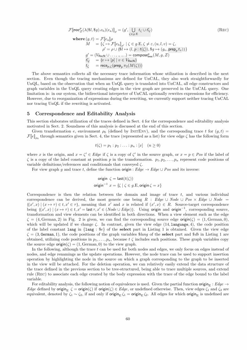
F [[recpZ(λ($l , $g).eb)(ea)]]ρ = (g′,
∪ζ∈g.E
tζ ∪ t′V)
where (g, t) = F [[ea]]ρM = {ζ 7→ F [[eb]]ρ′ | ζ ∈ g.E, ζ 6= ε, (u, l, v) = ζ,
ρ′ = ρ ∪ {$l 7→ (l, p : t(ζ)), $g 7→ (gv, prepp tv)}}g′ = (VRecN ∪ . . . , , , ) = composep
rec(M, g, Z)t′V = {v 7→ [p] | v ∈ VRecN}tζ = recep,ζ(prepp π2(M(ζ)))
(Rec)
The above semantics collects all the necessary trace information whose utilization is described in the nextsection. Even though the tracing mechanisms are defined for UnCAL, they also work straightforwardly forUnQL, based on the observation that when an UnQL query is translated into UnCAL, all edge constructors andgraph variables in the UnQL query creating edges in the view graph are preserved in the UnCAL query. Onelimitation is: in our system, the bidirectional interpreter of UnCAL optionally rewrites expressions for efficiency.However, due to reorganization of expressions during the rewriting, we currently support neither tracing UnCALnor tracing UnQL if the rewriting is activated.
5 Correspondence and Editability Analysis
This section elaborates utilization of the traces defined in Sect. 4 for the correspondence and editability analysismotivated in Sect. 2. Soundness of this analysis is discussed at the end of this section.
Given transformation e, environment ρ0 (defined by InitEnv), and the corresponding trace t for (g, t) =F [[e]]ρ0
through semantics given in Sect. 4, the trace (represented as a list) for view edge ζ has the following form
t(ζ) = p1 : p2 : . . . : pn : [x] (n ≥ 0)
where x is the origin, and x = ζ ′ ∈ Edge if ζ is a copy of ζ ′ in the source graph, or x = p ∈ Pos if the label ofζ is a copy of the label constant at position p in the transformation. p1, p2, . . . , pn represent code positions ofvariable definitions/references and conditionals that conveyed ζ.
For view graph g and trace t, define the function origin : Edge → Edge ∪ Pos and its inverse:
origin ζ = last(t(ζ))
origin−1 x = {ζ | ζ ∈ g.E, origin ζ = x}
Correspondence is then the relation between the domain and image of trace t, and various individualcorrespondence can be derived, the most generic one being R : Edge ∪ Node ∪ Pos × Edge ∪ Node ={(x′, x) | (x 7→ τ) ∈ t, x′ ∈ τ}, meaning that x′ and x is related if (x′, x) ∈ R. Source-target correspondencebeing {(x′, x) | (x 7→ τ) ∈ t, x′ = last τ, x′ ∈ (Node ∪ Edge)}. Using origin and origin−1, corresponding source,transformation and view elements can be identified in both directions. When a view element such as the edgeζ = (4, German, 2) in Fig. 2 is given, we can find the corresponding source edge origin(ζ) = (1, German, 0),which will be updated if we change ζ. In contrast, given the view edge (14, language, 4), the code positionof the label constant lang in {lang : $e} of the select part in Listing 1 is obtained. Given the view edgeζ = (3, German, 1), the code positions of the graph variables $lang of the select part and $db in Listing 1 areobtained, utilizing code positions in p1, . . . , pn, because t ζ includes such positions. These graph variables copythe source edge origin(ζ) = (1, German, 0) to the view graph.
In the following, although the trace t can be used for both nodes and edges, we only focus on edges instead ofnodes, and edge renamings as the update operations. However, the node trace can be used to support insertionoperation by highlighting the node in the source on which a graph corresponding to the graph to be insertedin the view will be attached. For the deletion operation, we can relatively easily extend the data structure ofthe trace defined in the previous section to be tree-structured, being able to trace multiple sources, and extendrule (Rec) to associate each edge created by the body expression with the trace of the edge bound to the labelvariable.
For editability analysis, the following notion of equivalence is used. Given the partial function originE : Edge →Edge defined by originE ζ = origin(ζ) if origin(ζ) ∈ Edge, or undefined otherwise. Then, view edges ζ1 and ζ2 areequivalent, denoted by ζ1 ∼ ζ2, if and only if originE ζ1 = originE ζ2. All edges for which originE is undefined are
60

considered equivalent. The equivalence class for edge ζ is denoted by [ζ]∼. We define our updates as upd : Updwhere Upd = Edge → Label , an expression and its environment at position p as expr : Pos → Expr × Env ,and update propagation along trace t as prop : Env → Upd → Env . Then, our editability analysis is defined asfollows.
Definition 1 (Editability checking). Given (g, t) = F [[e]]ρ0and update upd on g, editability checking succeeds if
all the following three conditions are satisfied.1. For all updated edges ζ, other view edges in [ζ]∼ are unchanged or consistently updated, i.e.,
∀ζ ∈ dom(upd).∀ζ ′ ∈ [ζ]∼.ζ ′ /∈ dom(upd) ∨ upd(ζ) = upd(ζ ′).2. For every if eB . . . expression in the backward evaluation path, applying the edit to the binding does not
change the condition, i.e., ∀p ∈ {∪[p | p ∈ t(ζ), p ∈ Pos] | ζ ∈ dom(upd)}, expr(p) = (if eB . . . , ρ),F [[eB]]ρ =F [[eB]]prop(ρ,upd). For the case of label variables, this interference can be checked by $l ∈ FV(eB), ρ′($l) =
( , τ), last(τ) = ζ ′ for ζ ′ = originE ζ. Weakened version for graph variables is: ∀$g ∈ FV(eB).(g′, t′) =ρ′($g),∀ζ ′′ ∈ g′.E. last(t′((ζ ′′)) 6= originE(ζ) for all ζ ∈ dom(upd).
3. No edited edge trace to code position, i.e., ∀ζ ∈ dom(upd). origin(ζ) /∈ Pos.
Further, we recap all the three run-time errors to reject updates [13] as (1) failure at environment merging ](”inconsistent change detected”), (2) failure at B[[if . . .]] (”branch behavior changed”) and (3) failure at BL[[a]](”nomodifications allowed for label literals.”). Then the following lemmas hold.
Lemma 1. Condition 1 in Def. 1 is false iff error (1) occurs.
Lemma 2. Error (2) implies condition 2 in Def. 1 is false.
Lemma 3. Condition 3 in Def. 1 is false iff error (3) occurs.
Based on these lemmas, we have the following theorem.
Theorem 1 (Soundness of editability analysis). Given forward transformation (g, t) = F [[e]]ρ0and update upd
on g to g′, success of editability checking in Def. 1 implies B[[e]](ρ0, g′) defined and results in prop(ρ0, upd).
Thus edit on the view edge ζ with ζ ′ = originE ζ defined is propagable to ζ ′ in the source graph by B[[]], whenthe checking in Def. 1 succeeds. An edit on the view edge ζ with origin(ζ) = p ∈ Pos is not propagable to thesource by Lemma 3. Editing label constant at p in the transformation would achieve the edits, with possible sideeffects through other copies of the label constant.
Consider the example in Listing 1 with the source graph of Fig. 1 and view graph of Fig. 2. We get four equiv-alence classes, one each for the source edges (1, German, 0), (3, Europe, 2), (5, Austrian, 4) and (11, German, 10),as well as the class that violate condition 3. For view edge ζ = (3, German, 1), we have (4, German, 2) ∈ [ζ]∼ viaoriginE ζ = (1, German, 0), so these equivalent edges can be selected simultaneously, inconsistent edits on whichcan be prevented (Lem. 1). Direct edits of the view edge ζ = (0, result, 14) are suppressed since origin ζ ∈ Pos(Lem. 3). On condition 2, when the view edge ζ = (7, Europe, 5) is given, all the code positions in t ζ ′′ forζ ′′ ∈ originE
−1(originE ζ) are checked if the positions represent conditionals that refer variables, change of thosebinding would change the conditions and would be rejected by B. We obtain the position for variable reference$l in the condition ($l = Europe) for warning.
Soundness Proof of the Editability Analysis
Cases in which completeness is lost: Note that system may choose the weakened version of condition 2, andjust issue warning (i.e., whenever the edge being updated has common source edge with any variable referenceoccurring free in any of the conditional expressions along the execution path), because when condition includesnot only the simple label comparison expressions but also graph emptiness checking by isEmpty, the cost of fullychecking the change of the condition may amount to re-executing the most part of the forward transformation.If this warning-only strategy is chosen, backward transformation may succeed despite this warning, because thewarning does not necessarily mean condition value changes. Therefore, the checking is not complete (may warnsome safe updates). We argue that this “false alarm” is not so problematic in practice, with the following reasons.The argument of isEmpty usually includes select to test an existence of certain graph pattern. So we furtheranalyze conditions in select down to simple label equivalence check. If the argument is a bare graph variablereference, then we analyze its binder. If the graph variable is $db (the entire input graph), then any changes
61

cause false alarms. This predicate may be used only for debugging purpose to exclude empty source graphs, butotherwise we don’t think we frequently encounter this situation.
Now we provide a proof sketch. First, we prove Lemma 3. We do this by parallel case analysis on augmentedforward semantics and backward semantics [13].Base case No edit is possible for {}, () and &y that produce no edge. For a transformation {a : e′}p and the
view graph as va //G, since a is a constant, augmented forward semantics generates code position p as
trace, which violates condition 3 when a is being updated. Backward semantics rejects with error (3).Inductive case
Transformation {$l : e′}p and the view graph as vl //G: Update on l to l′ will be handled by the
backward semantics of $l , which updates its reference. Suppose it is introduced by an expression llet $l =a in {$l : e′} . . .. Then binding $l 7→ l′ is generated and it is passed to the backward evaluation of labelexpression a, which is constant. So no value other than a is allowed. So backward transformation fails witherror (3). The trace generates code position of label constant a, which also signals violation of condition 3.If $l is bound by rec(λ($l , ).{$l : e1})(e2), then the update is also translated to the argument expression e2,so if corresponding part in e2 originates from a label constant, then the condition is violated and backwardtransformation fails similarly.e1 ∪ e2, e1 ⊕ e2, e1 @ e2 : We reduce the backward transformation to that of subexpressions, assumingdecomposition operation for each operator. So assuming Lemma 3 for these subexpressions, Lemma 3 holdsfor entire expression. Similar argument applies for cycle(e), & := e and if then e1 else e2.rec(e1)(e2): What is produced as a trace depends on e1 and e2. Assuming the decomposition of targetgraph, the backward evaluation is reduced to those of e1 and e2. The only interesting case is a graph variablereference as (sub) expression. The update on the target graph that was produced by the variable referenceis reduced to updated graph variable bindings, and the bound graph is aggregated for each edge in the inputgraph that was produced by e2, and passed to the backward evaluation of e2. The trace, on the other hand,is produced by e2 and combined with the trace by e1. If e1 is a graph variable reference, then the (sub)trace induced from the trace from e2 is used, so the edge that trace back to constant is inherited in thetrace of the result of rec, so attempt to update an edge that traces back to the constant produced by e2
and carried by the graph variable reference is signaled with condition 3. So, assuming Lemma 3 on e2 byinduction hypothesis, Lemma 3 holds for the entire expression.Thus conclude the proof for Lemma 3.
Next we prove Lemma 1. When violation of 1 is signaled, multiple edge labels with the same equivalence classis updated to different values. The proof can be conducted similarly to the case for Lemma 3, except that wefocus on multiple edge labels generated by different subexpressions of the transformation.{$l : $g}: Suppose bindings $l 7→ a and $g 7→ {b : G} are generated by updates on the target graph. Further,suppose these bindings are generated by rec(λ($l ′, ). rec(λ($l , $g).{$l : $g})({$l ′ : {$l ′ : {}}}))($db) as the innerbody expression of rec and $db is bound to graph {x : {}}. Then, backward evaluation of the argument expressionin the inner rec, i.e., {$l ′ : {$l ′ : {}}} will produce the bindings $l ′ 7→ a and $l ′ 7→ b for the first label expression$l ′ and the label construction expression {$l ′ : {}}, respectively, and merge these bindings by ] operator relativeto original binding $l ′ 7→ x. Then backward transformation fails because of the conflicting bindings. In thiscase, the augmented forward semantics also allocate the top and the following edge the same origin edge, so theupdate signals violation of condition 1. So violation of condition 1 coincides failed backward transformation.Similar situation can be observed for graph constructors ∪, ⊕ and @ that unifies the graphs, when conflictingupdates are attempted to edges originated from identical edges. The merge phase for the subexpressions in thebackward transformation causes the failure. Note that the duplicate is propagated through variable bindings,so conflicting updates can be detected within the target graph created by a single graph variable reference, likelet $g ′ = rec(λ($l ′, ). rec(λ($l , $g).{$l : $g})({$l ′ : {$l ′ : {}}}))($db) in $g ′. The failure takes place in the letexpression in this case. We omit the detailed case analysis here.
For the Lemma 2, its proof is straightforward by the warning algorithm in the long version. Note that ifwe exclude the update on target that causes violation of condition 2, we have soundness and completeness. Ingeneral, we only have soundness. This concludes the proof sketch.
6 Related Work
Our novelty is to analyze editability using traces in compositional bidirectional graph transformations.Tracing mechanism. Traceability is studied enthusiastically in model-driven engineering (MDE) [9, 25]. Van
62

Amstel et al. proposed a visualization framework TraceVis for chains of ATL model transformations [30].Systematic augmentation of the trace-generating capability with model transformations [22] is achieved byhigher-order model transformations [29]. Although they also trace between source, transformation and target,we also use the trace for editability analysis. We can help improve this kind of unidirectional tool. Grain size oftransformation trace in TraceVis is at ATL rule level, while our trace is more fine grained. If TraceVis refinesthe transformation trace to support inspection of guards (conditions), they can also support control flow changeanalysis. To do so, ATL engine may be extended to maintain the variable binding environment similar to oursat run-time, and use it to trace bindings within the guards.
Our own previous work [13] introduced the trace generation mechanism, but the main objective was thebidirectionalization itself. The notion of traces has been extensively studied in a more general context ofcomputations, like provenance traces [4] for the nested relational calculus.
Triple Graph Grammars (TGG) [26] and frameworks based on them are studied extensively and are appliedto MDE [1] including traceability [11]. They are based on graph rewriting rules consisting of triples of source andtarget graph pattern, and the correspondence graph in-between which explicitly contains the trace information.Grammar rules are used to create new elements in source, correspondence and view graphs consistently. Byiterating over items in the correspondence graph, incremental TGG approaches can also work with updatesand deletions of elements [10]. The transformation language UnQL is compositional in that the target of a(sub)transformation can be the source of another (sub)transformation, while TGG is not. Our tracing overcompositions are achieved by keeping track of variable bindings.
Xiong et al. [32]’s traces are editing operations (including deletion, insertion and replacement) embedded inmodel elements. They are translated along with transformation (in ATL bytecode). They check control flowchanges in these embedded operations after finishing backward transformations and reject updates when thesechanges are detected. ATL level trace could have been computed using our approach for correspondence analysis.
Target Element Classification and Editability Analysis. Model element classification has been studiedin the context of Precedence Triple Graph Grammars [23]. Though the motivation is not directly related toours, their classification is indeed similar in the sense that both group elements in graphs. The difference is thatthe equivalence class in [23] is defined such that all the elements in the class are affected in a similar manner(e.g., created simultaneously) while in our equivalence class, members are defined only on the target side, andthey are originated from the same source edge, so edits on any member result in edits on the source edge. Theequivalence class in [23] may correspond to the subgraph created by the same ”bulk” by the body expressionof rec with respect to common edge produced by the argument expression, so that when the common edge isdeleted, then all the edges in the bulk are deleted simultaneously.
Another well-studied bidirectional transformation framework called semantic bidirectionalization [31] gener-ates a table of correspondence between elements in the source and those in the target to guide the reflection ofupdates over polymorphic transformations, without inspecting the forward transformation code (thus called se-mantic). The entries in the target side of the table can be considered as equivalence classes to detect inconsistentupdates on multiple target elements corresponding identical source element. Although UnCAL transformationsare not polymorphic in general because of the label comparison in the if conditionals with constant labels, pro-hibiting the semantic bidirectionalization approach. Matsuda and Wang [24] relaxed this limitation by run-timerecording and change checking of the branching behaviors to reject updates causing such change. They also copewith data constructed during transformation (corresponding to constant edges in our transformation). So ourframework is close to theirs, though we utilize the syntax of transformation. We can trace nodes (though wefocused on edge tracing in this paper) while theirs cannot.
Hu et al. [21] treat duplications explicitly by a primitive Dup. They do not highlight duplicates in the view,rather they rely on another forward transformation to complete the propagation among duplicates.
7 Conclusion
In this paper, we proposed, within a compositional bidirectional graph transformation framework based onstructural recursion, a technique for analyzing the correspondence between source, transformation and target aswell as to classifying edges according to their editability. We achieve this by augmenting the forward semanticswith explicit correspondence traces. The incorporation of this technique into the GUI enables the user to clearlyvisualize the correspondence. Moreover, prohibited edits such as changing a constant edge and updating a groupof edges inconsistently are disabled. This allows the user to predict violated updates and thus do not attemptthem at the first place. In this paper we only focused on edge-reaming as edit operation but the proposed
63

framework can also support edge-deletion by slight extension, while insertion handling can be supported by thepresent node tracing.
As a future work, we would like to utilize the proposed framework to optimize the performance of edge deletionand subgraph insertion using the backward transformation semantics for in-place update semantics, because wecurrently handle these update operations by different algorithms. In particular, insertions use a general inversionstrategy which is costly. We already have limited support in this direction, however we are still to establishformal bidirectional properties for complex expressions. Leveraging the traces in the forward semantics indicatingwhich edge is involved in the branching behavior, we could safely determine the part that accepts the insertionor deletion of that part reusing the in-place update semantics, thus achieving “cheap backward transformation”.The proposed mechanism can be used for any other trace-based approaches, unidirectional or bidirectional, aswe discussed in Section 6, and we would like to pursue this direction as well.
Acknowledgments The authors would like to thank Zhenjiang Hu, Hiroyuki Kato and other IPL members,and AtlanMod team for their valuable comments. We also thank the reviewers for their constructive feedbacks.The project was supported by the International Internship Program of the National Institute of Informatics.
References
[1] Carsten Amelunxen, Felix Klar, Alexander Konigs, Tobias Rotschke, and Andy Schurr. Metamodel-basedtool integration with MOFLON. In ICSE ’08, pages 807–810. ACM, 2008.
[2] Francois Bancilhon and Nicolas Spyratos. Update semantics of relational views. ACM Trans. DatabaseSyst., 6(4):557–575, 1981.
[3] Peter Buneman, Mary Fernandez, and Dan Suciu. UnQL: a query language and algebra for semistructureddata based on structural recursion. The VLDB Journal, 9(1):76–110, 2000.
[4] James Cheney, Umut A. Acar, and Amal Ahmed. Provenance traces. CoRR, abs/0812.0564, 2008.
[5] Krzysztof Czarnecki, J. Nathan Foster, Zhenjiang Hu, Ralf Lammel, Andy Schurr, and James F. Terwilliger.Bidirectional transformations: A cross-discipline perspective. In ICMT’09, pages 260–283, 2009.
[6] Zinovy Diskin, Yingfei Xiong, Krzysztof Czarnecki, Hartmut Ehrig, Frank Hermann, and Fernando Orejas.From state- to delta-based bidirectional model transformations: The symmetric case. In MODELS’11,volume 6981 of LNCS, pages 304–318. 2011.
[7] Romina Eramo, Alfonso Pierantonio, and Gianni Rosa. Uncertainty in bidirectional transformations. InProc. 6th International Workshop on Modeling in Software Engineering (MiSE), pages 37–42. ACM, 2014.
[8] J. Nathan Foster, Michael B. Greenwald, Jonathan T. Moore, Benjamin C. Pierce, and Alan Schmitt.Combinators for bidirectional tree transformations: A linguistic approach to the view-update problem.ACM Trans. Program. Lang. Syst., 29(3), 2007.
[9] Ismenia Galvao and Arda Goknil. Survey of traceability approaches in model-driven engineering. In EDOC’07, pages 313–324. IEEE Computer Society, 2007.
[10] Holger Giese and Robert Wagner. From model transformation to incremental bidirectional model synchro-nization. Software & Systems Modeling, 8(1):21–43, 2008.
[11] Esther Guerra, Juan de Lara, Dimitrios S. Kolovos, and Richard F. Paige. Inter-modelling: From theory topractice. In MODELS’10, pages 376–391. Springer-Verlag, 2010.
[12] Soichiro Hidaka, Martin Billes, Quang Minh Tran, and Kazutaka Matsuda. Trace-based approach toeditability and correspondence analysis for bidirectional graph transformations. Technical report, May2015. http://www.prg.nii.ac.jp/projects/gtcontrib/cmpbx/tesem.pdf.
[13] Soichiro Hidaka, Zhenjiang Hu, Kazuhiro Inaba, Hiroyuki Kato, Kazutaka Matsuda, and Keisuke Nakano.Bidirectionalizing graph transformations. In ICFP’10, pages 205–216. ACM, 2010.
64

[14] Soichiro Hidaka, Zhenjiang Hu, Kazuhiro Inaba, Hiroyuki Kato, Kazutaka Matsuda, Keisuke Nakano, andIsao Sasano. Marker-directed optimization of UnCAL graph transformations. In LOPSTR’11, RevisedSelected Papers, volume 7225 of LNCS, pages 123–138, July 2012.
[15] Soichiro Hidaka, Zhenjiang Hu, Kazuhiro Inaba, Hiroyuki Kato, and Keisuke Nakano. GRoundTram: Anintegrated framework for developing well-behaved bidirectional model transformations (short paper). InASE’11, pages 480–483. IEEE, 2011.
[16] Soichiro Hidaka, Zhenjiang Hu, Kazuhiro Inaba, Hiroyuki Kato, and Keisuke Nakano. GRoundTram:An Integrated Framework for Developing Well-Behaved Bidirectional Model Transformations. Progressin Informatics, (10):131–148, March 2013. Journal version of [15].
[17] Soichiro Hidaka, Zhenjiang Hu, Hiroyuki Kato, and Keisuke Nakano. Towards compostional approach tomodel transformations for software development. Technical Report GRACE-TR08-01, GRACE Center,National Institute of Informatics, August 2008.
[18] Soichiro Hidaka, Zhenjiang Hu, Hiroyuki Kato, and Keisuke Nakano. A compositional approach to bidi-rectional model transformation. In ICSE New Ideas and Emerging Results track, ICSE Companion, pages235–238. IEEE, 2009.
[19] Soichiro Hidaka, Zhenjiang Hu, Hiroyuki Kato, and Keisuke Nakano. Towards a compositional approach tomodel transformation for software development. In Proc. of the 2009 ACM symposium on Applied Computing(SAC), pages 468–475. ACM, 2009.
[20] Soichiro Hidaka and James F. Terwilliger. Preface to the third international workshop on bidirectionaltransformations. In Workshops of the EDBT/ICDT 2014, pages 61–62, 2014.
[21] Zhenjiang Hu, Shin-Cheng Mu, and Masato Takeichi. A programmable editor for developing structureddocuments based on bidirectional transformations. In PEPM ’04, pages 178–189, 2004.
[22] Frederic Jouault. Loosely Coupled Traceability for ATL. In ECMDA Traceability Workshop (ECMDA-TW),pages 29–37, 2005.
[23] Marius Lauder, Anthony Anjorin, Gergely Varro, and Andy Schurr. Efficient model synchronization withprecedence triple graph grammars. In ICGT’12, pages 401–415. Springer-Verlag, 2012.
[24] Kazutaka Matsuda and Meng Wang. “bidirectionalization for free” for monomorphic transformations.Science of Computer Programming, 2014. DOI:10.1016/j.scico.2014.07.008.
[25] Richard F. Paige, Nikolaos Drivalos, Dimitrios S. Kolovos, Kiran J. Fernandes, Christopher Power, Goran K.Olsen, and Steffen Zschaler. Rigorous identification and encoding of trace-links in model-driven engineering.Softw. Syst. Model., 10(4):469–487, October 2011.
[26] Andy Schurr. Specification of graph translators with triple graph grammars. In WG ’94, volume 903 ofLNCS, pages 151–163, June 1995.
[27] Perdita Stevens. Bidirectional model transformations in QVT: semantic issues and open questions. Softwareand System Modeling, 9(1):7–20, 2010.
[28] Perdita Stevens. Bidirectionally tolerating inconsistency: Partial transformations. In FASE’14, volume 8411of LNCS, pages 32–46, 2014.
[29] Massimo Tisi, Frederic Jouault, Piero Fraternali, Stefano Ceri, and Jean Bezivin. On the use of higher-ordermodel transformations. In ECMDA-FA’09, volume 5562 of LNCS, pages 18–33, 2009.
[30] Marcel F. van Amstel, Mark G. J. van den Brand, and Alexander Serebrenik. Traceability visualization inmodel transformations with TraceVis. In ICMT’12, pages 152–159, 2012.
[31] Janis Voigtlander. Bidirectionalization for free! (pearl). In POPL ’09, pages 165–176. ACM, 2009.
[32] Yingfei Xiong, Dongxi Liu, Zhenjiang Hu, Haiyan Zhao, Masato Takeichi, and Hong Mei. Towards automaticmodel synchronization from model transformations. In ASE’07, pages 164–173, November 2007.
65