tracer sc system controller for bas systems · tracer® sc system controller fortracer building...
TRANSCRIPT

Tracer® SC System Controller
ForTracer Building Automated Systems
May 2015 BAS-PRC031N-EN
Product Catalog

© 2015Trane All rights reserved BAS-PRC031N-EN
Copyright
This document and the information in it are the property ofTrane, and may not be used orreproduced in whole or in part without written permission.Trane reserves the right to revise thispublication at any time, and to make changes to its content without obligation to notify any personof such revision or change.
Trademarks
All trademarks referenced in this document are the trademarks of their respective owners.

Table of Contents
Product Introduction . . . . . . . . . . . . . . . . . . . . . . . . . . . . . . . . . . . . . . . . . . . . . . . . . . . . 5
Tracer Building Automation System . . . . . . . . . . . . . . . . . . . . . . . . . . . . . . . . . . 6
Tracer SC System Architecture . . . . . . . . . . . . . . . . . . . . . . . . . . . . . . . . . . . . . . 7
BAS R’newal™ Program . . . . . . . . . . . . . . . . . . . . . . . . . . . . . . . . . . . . . . . . . . . . 8
Tracer® Communication Bridges . . . . . . . . . . . . . . . . . . . . . . . . . . . . . . . . . . . . . 8
Tracer SC Facilities . . . . . . . . . . . . . . . . . . . . . . . . . . . . . . . . . . . . . . . . . . . . . . . . . 9
User Interface . . . . . . . . . . . . . . . . . . . . . . . . . . . . . . . . . . . . . . . . . . . . . . . . . . . . . . . . . 10
Alarms . . . . . . . . . . . . . . . . . . . . . . . . . . . . . . . . . . . . . . . . . . . . . . . . . . . . . . . . . . 10
Data Logs . . . . . . . . . . . . . . . . . . . . . . . . . . . . . . . . . . . . . . . . . . . . . . . . . . . . . . . . 11
Schedules . . . . . . . . . . . . . . . . . . . . . . . . . . . . . . . . . . . . . . . . . . . . . . . . . . . . . . . . 12
Overrides . . . . . . . . . . . . . . . . . . . . . . . . . . . . . . . . . . . . . . . . . . . . . . . . . . . . . . . . 13
Reports . . . . . . . . . . . . . . . . . . . . . . . . . . . . . . . . . . . . . . . . . . . . . . . . . . . . . . . . . . 14
Graphics and the Tracer Graphics Editor . . . . . . . . . . . . . . . . . . . . . . . . . . . . . 15
Graphical and Bindable Widgets . . . . . . . . . . . . . . . . . . . . . . . . . . . . . . . . . . . . 17
Navigation Tree . . . . . . . . . . . . . . . . . . . . . . . . . . . . . . . . . . . . . . . . . . . . . . . . . . . 18
User Security . . . . . . . . . . . . . . . . . . . . . . . . . . . . . . . . . . . . . . . . . . . . . . . . . . . . . 18
System Control . . . . . . . . . . . . . . . . . . . . . . . . . . . . . . . . . . . . . . . . . . . . . . . . . . . . . . . . 19
Area Application . . . . . . . . . . . . . . . . . . . . . . . . . . . . . . . . . . . . . . . . . . . . . . . . . . 19
Variable Air Systems (VAS) . . . . . . . . . . . . . . . . . . . . . . . . . . . . . . . . . . . . . . . . 19
Chilled Plant Control (CPC) . . . . . . . . . . . . . . . . . . . . . . . . . . . . . . . . . . . . . . . . . 19
Trane EarthWise™ Systems . . . . . . . . . . . . . . . . . . . . . . . . . . . . . . . . . . . . . . . . 20
Tracer Graphical Programming (TGP2) . . . . . . . . . . . . . . . . . . . . . . . . . . . . . . 20
Unit Control . . . . . . . . . . . . . . . . . . . . . . . . . . . . . . . . . . . . . . . . . . . . . . . . . . . . . . . . . . . 22
BACnet (MS/TP) Unit Controllers Supported by Tracer SC . . . . . . . . . . . . . . 22
BACnet/IP Unit Controllers Supported by Tracer SC . . . . . . . . . . . . . . . . . . . 22
Air-Fi Wireless Unit Controllers Supported by Tracer SC . . . . . . . . . . . . . . . 22
LonTalk Unit Controllers Supported by Tracer SC . . . . . . . . . . . . . . . . . . . . . 22
Trane Legacy Unit Controllers (Comm3/4) Supported by Tracer SC . . . . . . 23
Resources . . . . . . . . . . . . . . . . . . . . . . . . . . . . . . . . . . . . . . . . . . . . . . . . . . . . . . . . . . . . 24
Specifications . . . . . . . . . . . . . . . . . . . . . . . . . . . . . . . . . . . . . . . . . . . . . . . . . . . . . . . . . 25
Hardware Components . . . . . . . . . . . . . . . . . . . . . . . . . . . . . . . . . . . . . . . . . . . . . . . . 28
Tracer SC System Controller . . . . . . . . . . . . . . . . . . . . . . . . . . . . . . . . . . . . . . . 28
Dimensions . . . . . . . . . . . . . . . . . . . . . . . . . . . . . . . . . . . . . . . . . . . . . . . . . . . . . . 29
Trane PM014 Power Supply Module . . . . . . . . . . . . . . . . . . . . . . . . . . . . . . . . . 29
Tracer® BACnet® Terminator . . . . . . . . . . . . . . . . . . . . . . . . . . . . . . . . . . . . . . . 30
BAS-PRC031N-EN 3

Medium Enclosure (optional) . . . . . . . . . . . . . . . . . . . . . . . . . . . . . . . . . . . . . . . 30
Large Enclosure (optional) . . . . . . . . . . . . . . . . . . . . . . . . . . . . . . . . . . . . . . . . . 32
4 BAS-PRC031N-EN

Product Introduction
Tracer® SC allows you to streamline facility management without reinventing the entire system.AddingTracer SC to your system provides a flexible, cost effective solution for buildingautomation, and managing the facility climate that can extend to lighting and energy consumption.
Accessible from most PCs, tablets and smart phones,Tracer SC eliminates the need for a dedicatedcomputer and monitor so you can manage system performance whenever and wherever it isconvenient.Tracer SC controller's simplified, Web-based management tool reduces scheduling,reporting and system application chores to simple "point and click" tasks.The intuitive online toolsprovide improved efficiencies, increased tenant comfort and reduced energy costs, which result inoperational cost-savings and a better bottom line.
Occupant comfort and energy savings• Tracer SC includes several factory engineered HVAC applications
that have been developed by HVAC system experts and tested on tens of thousands of facilities to ensure that your facility operates at its peak performance. These applications provide consistent comfort and improved indoor air quality, while reducing energy requirements.
• For any building owner concerned with energy, indoor air quality, and the environment, Trane EarthWise™ Systems represent a design philosophy whose time has come. EarthWise Systems provide documented sustainability of high efficiency and low emissions over the entire lifetime of the building.
• Tracer Graphical Programming (TGP2) is a powerful graphical program that can be used to customize factory applications or control non-HVAC equipment.
Access your facility from anywhere• Tracer SC is web-enabled and accessible from virtually any device
with a web browser. All of the most popular device types, operating systems, and browsers are supported.
• The Tracer® BAS Operator Suite is a mobile app that allows you to monitor and manage buildings from virtually anywhere, giving you greater freedom and constant peace of mind.
Support for open, standard protocols• Open, standard protocols are the key to enabling communication
among Trane and non-Trane HVAC equipment, as well as other complementary facility systems. These protocols enable communication across systems and vendors to ensure that your building operates at its best on day one and beyond.
• Tracer SC natively communicates to BACnet® and LonTalk controllers and is listed as a BACnet Building Controller (B-BC) by BACnet Test Labs (BTL).
• Tracer SC supports Trane®Air-Fi™ Wireless, providing standard wireless BACnet over Zigbee™ building automation between Trane BACnet controllers and zone sensors.
Support for Trane®Air-Fi™ Wireless• Trane Air-Fi Wireless brings maximum flexibility to your building
automation system.• For contractors, it significantly simplifies building controls projects
by minimizing the engineering, estimating and project management tasks associated with communication link. For building owners, it provides easier and more cost-effective controls upgrades and building expansion projects.
• Trane technology helps prepare your facilities for the future of building information. Trane Air-Fi Wireless runs BACnet protocol over ZigBee building automation standards. Trane Wireless COMM is the first HVAC manufacturer to be Zigbee Certified.
BAS-PRC031N-EN 5

Product Introduction
Tracer Building Automation System
From our industry-leading building automation systems to equipment controls and sensors,Traneoffers a complete controls portfolio to enable you to operate buildings at peak energy andoperational efficiency.
Trane controls are built on open, scalable platforms.They provide options to integrate with yourexisting equipment and controls, regardless of brand, and give you the latitude to easily expandinto other systems within your building, multiple buildings and buildings you'll add in the future.
6 BAS-PRC031N-EN

Product Introduction
Tracer SC System Architecture
Tracer SC is at the heart of aTracer building automation system.Tracer SC provides a web-basedfront end for your facility that can be accessed with most PCs, tablets and smart phones.Tracer SCincludes powerful, factory-engineered applications that are designed to provide the perfectbalance of energy efficiency and user comfort.Tracer SC communicates with a variety ofTrane andnon-Trane controllers using open, standard protocols, including BACnet and LonTalk. A diagramdepicting the high-level system architecture is shown in Figure 1.
Figure 1. Tracer building automation system structure
PC/Tablet/Phone with Web Browser
BAS-PRC031N-EN 7

Product Introduction
BAS R’newal™ Program
BAS R’newal is a newTrane building control systems upgrade program that helps customerstransition to our currentTracer SC system.The program makes it easier to upgrade existinginstalledTracer systems and non-Trane systems to the latest technologies including web-access,mobile access, intuitive user interfaces, and advanced features enabled byTrane IntelligentServices (TIS).The BAS R’newal program is enabled byTracer Communication Bridges, the detailsof which can be found in the following section.
Find out more about BAS R’newal at http://www.trane.com/commercial/north-america/us/en/services/upgrade-improve/r_newal_-programs.html.
Tracer® Communication Bridges
Tracer® Communications Bridges integrate legacy control products into currentTracer systems formonitoring and control purposes. See Figure 2, p. 9 for aTracer SC configuration that includesTracer communication bridges.
Tracer Communications Bridges use legacy communications protocols to access points stored inprevious-generation field-level controllers.The Bridges then convert the points to BACnet objectsand properties, which makes them available for system use through the BACnet/IPcommunications protocol.
Comm2 to BACnet/IP
This bridge is used to integrate up to three UCP1-controlled chillers (CenTraVac and Series-R) intoTracer systems for monitoring and control purposes. For more information, refer to the “Comm2to BACnet/IP Product Data Sheet,” BAS-PRC070.
Comm3/4 toTracer SC (enables the BAS R’newal program)
This bridge enables Comm3 and Comm4 devices to be integrated intoTracer SC systems, similarto current generation devices.The latest features and capabilities ofTracer SC can be accessedwithout needing to replace the existing Comm3 and Comm4 devices. For more information, referto the “Comm 3/4 toTracer SC Product Data Sheet,” BAS-PRC084.
N2 to BACnet/IP (enables the BAS R’newal program)
This bridge integrates Johnson Controls, Inc., N2 communicating controllers intoTraneTracercontrol systems.The N2 Bridge converts the N2 controllers into virtual BACnet devices for easyintegration intoTracer SC. For more information, refer to the“N2 to BACnet/IP Product Data Sheet,”BAS-PRC082.
8 BAS-PRC031N-EN

Product Introduction
Tracer SC Facilities
ATracer SC facility is defined as one Application SC and one or more associated Base SCs. A singlebuilding or site can contain more than one facility. See Figure 2 for an example of an SC facilityconfiguration.
The following attributes apply toTracer SC facilities:
• ATracer SC facility is limited to one Application SC.
• ATracer SC facility has one or more Base SCs.
• ATracer SC facility can support a maximum 240 devices.
• ATracer SC facility may be limited to 120 devices depending on the communications involved(see the following table for device capability).
Device Capability
Figure 2. Example of a single SC facility configuration
Communication Type Single SC Multi SC
Air-Fi™ Wireless Up to 120 devices Up to 240 devices
BACnet/MSTP Up to 120 devices Up to 240 devices
BACnet/IP Up to 240 devices Up to 240 devices
COMM 3/4/LON(individual or any combination)
Up to 120 devices Up to 120 devices
BAS-PRC031N-EN 9
r
ion
en
Expnavitree
Systenaviglinks
User Interface
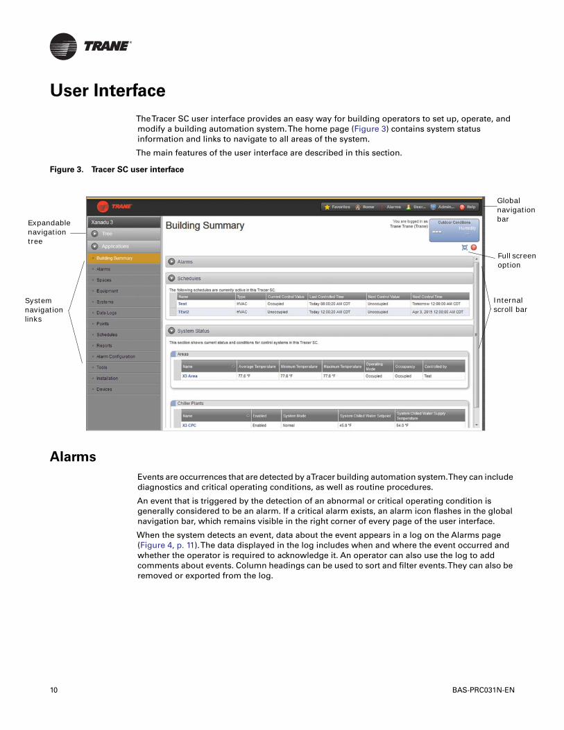
TheTracer SC user interface provides an easy way for building operators to set up, operate, andmodify a building automation system.The home page (Figure 3) contains system statusinformation and links to navigate to all areas of the system.
The main features of the user interface are described in this section.
Alarms
Events are occurrences that are detected by aTracer building automation system.They can includediagnostics and critical operating conditions, as well as routine procedures.
An event that is triggered by the detection of an abnormal or critical operating condition isgenerally considered to be an alarm. If a critical alarm exists, an alarm icon flashes in the globalnavigation bar, which remains visible in the right corner of every page of the user interface.
When the system detects an event, data about the event appears in a log on the Alarms page(Figure 4, p. 11).The data displayed in the log includes when and where the event occurred andwhether the operator is required to acknowledge it. An operator can also use the log to addcomments about events. Column headings can be used to sort and filter events.They can also beremoved or exported from the log.
Figure 3. Tracer SC user interface
Internal scroll ba
Global navigatbar
Full screoption
andable gation
m ation
10 BAS-PRC031N-EN

User Interface
The alarm handling capabilities ofTracer SC allow users to receive, view, acknowledge, and makecomments on building alarms.
Users can categorize alarms to determine how they appear in theAlarm log.A category is assignedto one of 255 priorities. In previous versions ofTracer SC, alarm categories were limited to fourtypes: Severe, Critical, Advisory, and Information. As ofTracer SC version 4.0, users can createadditional categories and select an accompanying icon. Benefits of customizing alarm categoriesinclude the ability to send a specific alarm to a specific person, and to differentiate criticalequipment alarms from others.
Data Logs
Data logs, also referred to as trends, allow users to produce a variety of data samples at definedintervals to show the historical and current status of the facility. Data logs record, in real-time, thevalue of a data point in the system and the time at which the value was recorded.
Data logs can be viewed in real-time, or at a later time.They can also be printed and saved. Withthe proper security access, system users can configure (create, delete, and update) and manage(clear, enable, and disable) data logs in the system. (See Figure 5, p. 12 for an example of a datalog.)
Figure 4. Alarms log
BAS-PRC031N-EN 11

User Interface
Schedules
Scheduling is one of a facility’s most important energy-saving strategies. It ensures that equipmentruns only when needed. Use schedules to:
• Keep equipment running at minimal energy-use levels on weekends and holidays
• Create exceptions to the standard schedule
• Perform optimal start and stop of equipment to optimize energy use while maintaining comfortrequirements
• Change setpoints at specific times of day
From the home page, you can select:
• All Schedules, which shows all schedules in the system
• Active Schedules, which shows only the active schedules in the system
Figure 6, p. 13 shows an example of an All Schedules page.
Figure 5. Data Logs example
12 BAS-PRC031N-EN

User Interface
Overrides
A typical challenge that facility managers have is maintaining the balance between automatic andmanual system control.Tracer SC provides multiple methods of overriding equipment,applications, and points while also ensuring that the proper balance of automatic and manualsystem control is kept.These methods include:
Permanent Overrides
The most typical use of a permanent override is through applications.Tracer SC provides the abilityto determine which user or application has performed an override to quickly determine who hasoverridden a setpoint.
Temporary Overrides
A common challenge in facilities is inadvertent overrides.Tracer SC provides a default overrideoption for users, which allows an override to expire after a period of time.This ensures thattemporary overrides do not inadvertently become permanent overrides.
All items in Override Report
It can be difficult to track down overrides that have become permanent and are causing a facilityto act differently than a facility manager expects.Tracer SC includes a standard report that allowsa user to quickly identify all points within the system that have been overridden. See Figure 7, p. 14.
Figure 6. Schedules
BAS-PRC031N-EN 13

User Interface
Reports
Standard reports forTrane equipment are available fromTracer SC.These reports provide avaluable source of data that can be used for record-keeping and troubleshooting.
Report types include:• Site reports• VAS commissioning reports• Points reports• Chiller reports
Report features include:
• Scheduling reports to run during specific date periods and run frequencies
• Specifying file storage options for scheduled reports
• Exporting reports to save to your PC as CSV, HTML, or PDF files
• Editing scheduled reports
See Figure 8, p. 15.
Figure 7. All Items in Override Report
14 BAS-PRC031N-EN

User Interface
Graphics and theTracer Graphics Editor
With theTracer Graphics Editor (TGE), available through theTracerTU service tool, users cancreate, edit, and publish graphics for use onTracer SC. Graphics on theTracer SC monitor andcontrol building equipment and applications.They can display data related to climate, lighting, andother controllable operations.They can be used to change setpoints and to override equipmentoperation.
TGE can be used to align graphical elements, determine which elements appear on top, andperform cut, copy, and paste functions.
Graphics can include:
• Any data that is available in the system as a numerical or text value
• Analog values that can change colors if they deviate from a desired value
• Multiple graphic images in JPEG, GIF, and animated GIF formats
• Visual elements from the building, such as floor plans or exterior views from CAD drawings
• Digital photography in JPG and GIF formats
• Animated images to represent binary and analog values
• Target buttons that provide links to related sources
• User controls including push buttons, check boxes, drop-down list boxes, and entry fields
Figure 8. Reports
BAS-PRC031N-EN 15
User Interface
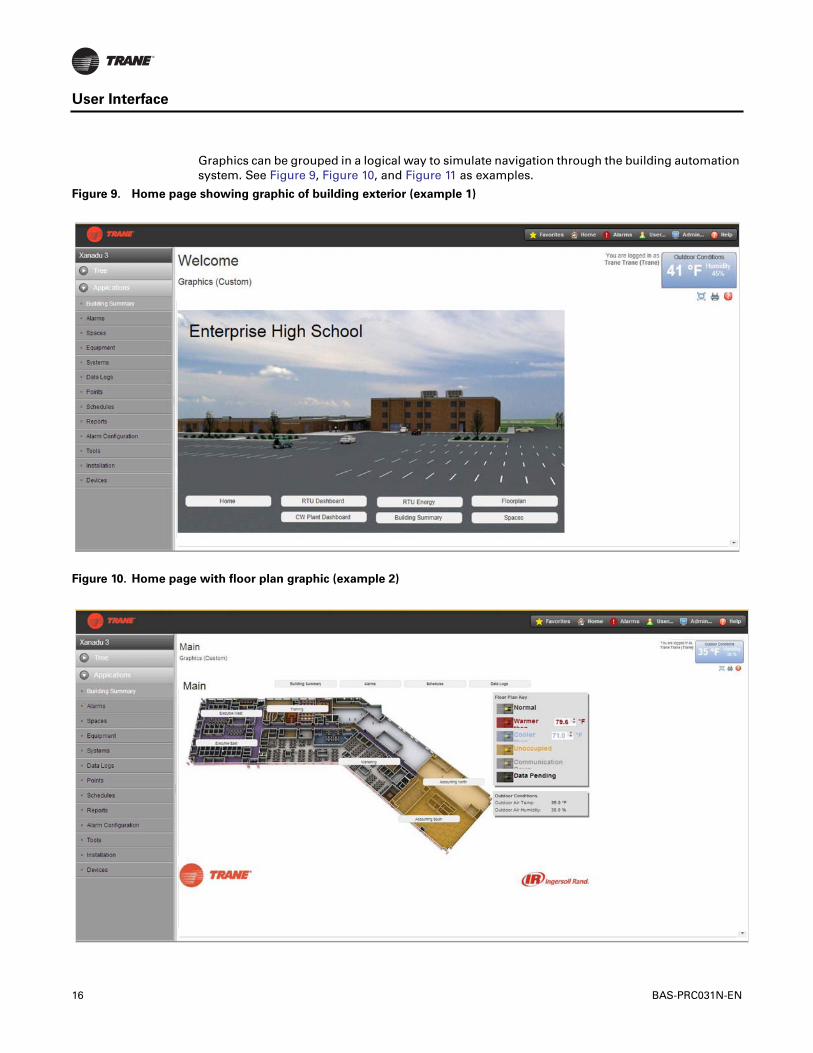
Graphics can be grouped in a logical way to simulate navigation through the building automationsystem. See Figure 9, Figure 10, and Figure 11 as examples.
Figure 9. Home page showing graphic of building exterior (example 1)
Figure 10. Home page with floor plan graphic (example 2)
16 BAS-PRC031N-EN

User Interface
Graphical and Bindable Widgets
New inTracer SC V4.1 is the option to incorporate graphical and bindable widgets intoTracer SCcustom pages. Graphical widget components provide a visual representation of an analog processsuch as the current temperature or the current level of a water tank. Bindable widgets providecontrol and display of system controls and states in a simplified way.The following figure providesan example of each.
Figure 12. Widget examples
Figure 11. Equipment status graphic (example 3)
Bindable widget (Override)
Graphical widget (gauge)
BAS-PRC031N-EN 17

User Interface
NavigationTree
The navigation tree contains the logically ordered and grouped content of all the elements of yourHVAC system.The navigation tree populates automatically when spaces, systems, points, andequipment are installed. A navigation tree provides an alternate way to navigate through the userinterface (Figure 13).
The navigation tree consists of nodes, display text, and icons.You build the tree by choosingdisplay text for nodes, arranging the nodes, and assigning associated graphics to them.Thegraphics represent equipment and areas of the facility.
User Security
A sophisticated password system protects aTracer system from unauthorized access. Operatorsare assigned a role, which defines their access rights. Operators have access only to those featuresthat are defined in their roles. Several predefined roles can be selected from theTracer SC interfaceand roles can also be customized.An operator with administrative-level security can manage usersand roles and has the ability to reset passwords.
Figure 13. Navigation tree example
Click to open the navigation tree
Click to expand the contents of a node
Use the edit bar to move nodes, rename nodes, add graphics, or remove items from the tree
18 BAS-PRC031N-EN
System Control
Tracer SC includes a powerful system control engine. EveryTracer SC ships with several factoryengineered HVAC applications, support forTrane Earthwise™ Systems, and a powerful customgraphical programming language.
Area Application
The Area application coordinates groups of equipment that represent the tenant or occupantorganization within a building, which allows for standard calculations/functions and a simplifieduser interaction with the facility.TheArea application allows users to assign unit controllers, binaryoutputs, and binary values as members of a common area.The area application can be configuredto use multiple algorithms, along with area temperatures and humidity inputs, to make aneconomizing decision.
The Area application also supports:
• Optimal start/stop
• Humidity pulldown
• Night purge
• Unoccupied heating/cooling setpoints
• Unoccupied humidify/dehumidify
• Timed override functions
Additionally, the Area application allows users to efficiently perform a single operation, such aschanging a setpoint, creating a schedule, performing an override, and apply it to all members ofthe area. For more information, see the “Air Systems forTracer SC Applications Guide”,BAS-APG007.
Variable Air Systems (VAS)
The Variable-Air-Volume Air System (VAS) coordinates the control of air handlers, rooftop units,and variable air volume terminal units.TheTracer SC VAS includes valuable tools to help managetasks that were previously problematic and time consuming, such as:
• Determining Heat/Cool mode for changeover systems
• Coordinating AHU and VAV box operation
• Commissioning VAV boxes
• Scheduling common spaces
• Optimizing ventilation
• Optimizing duct static pressure
For more information, see the “Air Systems forTracer SC Applications Guide”, BAS-APG007.
Chilled Plant Control (CPC)
The Chiller Plant Control (CPC) application permits users to configure a chiller plant for optimalefficiency and reliability, and provides a means for monitoring and controlling the daily operation.Depending upon the many possible chiller plant configurations and design differences, the CPCapplication can do the following:
• Provide overall chiller plant status information and alarms to local and remoteTracer SC users
• Enable or disable chiller plants
• Start, stop, and monitor the status of system chilled water pumps
• Calculate individual chilled water setpoints for individual chillers in series chiller plants
BAS-PRC031N-EN 19
System Control
• Request when chillers are added or subtracted according to building load requirements anduser-specified add and subtract logic
• Rotate chillers according to user-defined intervals
• Remove chillers from the rotation in the event
For more information, see the “Chiller Plant Control forTracer SC Application Guide”,BAS-APG012.
Trane EarthWise™ Systems
For any building owner concerned with energy, indoor air quality, and the environment,Trane'sEarthWise Systems represent a design philosophy whose time has come. EarthWise and EarthWiseElite Systems, by definition, provide documented sustainability of high efficiency and lowemissions over the entire lifetime of the building.
Trane EarthWise Systems include:
• Low Flow, LowTemperature CentraVac™ Chilled Water Systems
• Ice Enhanced, Air-Cooled Chiller Plant
• Intelligent Variable Air System for chilled-water applications
• Intelligent Variable Air System for IntelliPak™ rooftop applications
• Central Geothermal Systems
Find out more about EarthWise at http://www.trane.com/commercial/north-america/us/en/products-systems/earthwise-systems.html
Tracer Graphical Programming (TGP2)
Tracer Graphical Programming (TGP2) is a powerful graphical program that allows you tocustomizeTracer system applications.TGP2 routines are typically used for sequencing equipment,calculating setpoints and values, and performing shutdown sequences. See Figure 14, p. 21 for anexample.
Note: TGP2 is available through theTracerTU service tool.
20 BAS-PRC031N-EN

System Control
Figure 14. TGP2 example
BAS-PRC031N-EN 21

Unit Control
Unit controllers provide all necessary unit control functions.They operate associated unitaryequipment, while ensuring that all built-in safety features are enabled and that diagnostics areissued.
Each controller is designed to operate in stand-alone mode.Therefore, if system control fails, unitoperation can continue.
Unit controllers installed on aTracer SC can be a combination of the following BACnet and LonTalkunit controllers:
BACnet (MS/TP) Unit Controllers Supported byTracer SC
• Tracer UC210 unit controller for variable-air-volume (VAV) equipment
• Tracer UC400 unit controller for variable-air-volume (VAV) equipment
• Tracer UC400 unit controller for programmable equipment
• Tracer UC800/AdaptiView unit controller for CenTraVac chillers
• BCI-I: BACnet communications interface for IntelliPak system
• BCI-C: BACnet communications interface for chillers
• BCI-R: BACnet communications interface for ReliaTel
• Non-Trane BACnet (MS/TP) devices
BACnet/IP Unit Controllers Supported byTracer SC
• Tracer UC600 Programmable controller
• Non-Trane BACnet/IP devices
Air-Fi Wireless Unit Controllers Supported byTracer SC
• Tracer UC210 unit controller for variable-air-volume (VAV) equipment
• Tracer UC400 unit controller for variable-air-volume (VAV) equipment
• Tracer UC400 unit controller for programmable equipment
• Tracer UC600 unit controller for Air Handler (AHU) equipment
• Tracer UC600 unit controller for programmable equipment
LonTalk Unit Controllers Supported byTracer SC
• Tracer AH540/541 air-handler controller
• Tracer MP501 multi-purpose controller
• Tracer MP503 input/output module
• Tracer MP580/581 programmable controller
• Tracer VV550/551 VAV controller
• Tracer ZN510/511 zone controller
• Tracer ZN517 unit controller
• Tracer ZN520/521 zone controller
• Tracer ZN523 zone controller
• Tracer ZN524 water-source heat pump unit controller
• Tracer ZN525 zone controller
22 BAS-PRC031N-EN

Unit Control
• Tracer CH530 chiller controller
• Tracer CH532 chiller controller
• LCI-C: LonTalk communications interface for chillers
• LCI-I: LonTalk communications interface for IntelliPak systems
• LCI-R: LonTalk communications interface for ReliaTel systems
• Non-Trane LonTalk devices using SCC, DAC, and chiller profiles, devices that support LonTalkstandard network generic variables, and devices with Standard Network VariableTypes(SNVTs)
Trane Legacy Unit Controllers (Comm3/4) Supported byTracer SC
Note: The following devices are supported through the use of Legacy Comm Bridge.
• Variable Air Volume (VAV I, II, III, IV)
• IntelliPak
• Voyager
• Commercial Self-Contained (CSC)
• Thermostat Control Module (TCM)
• Programmable Control Module (PCM)
• Universal Programmable Control Module (UPCM)
• Terminal Unit Controller (TUC)
• Centrifugal Chillers (UCP2)
• Helical Rotary Chillers (UCP2)
• CGX Chillers
• Series-R Chillers (RTA/RTW)
BAS-PRC031N-EN 23

Resources
The following resources are available for managingTracer building automation systems:
Tracer SC Installation, setup, and operation
• Tracer SC System Controller Installation and Setup Guide (BAS-SVX31)• Tracer SC online help• Tracer SC Installation Instructions (X39641154)• BACnet Wiring Best Practices andTroubleshooting (BAS-SVX51)
Programming
• Tracer Graphical Programming (TGP2) Editor
• Tracer Graphical Programming (TGP2) Application Guide (BAS-APG008) and online help
• Tracer UC400/UC600 withTracer SC Programming Guide (BAS-SVP06)
HVAC applications
• Tracer SC Air Systems Application Guide (BAS-APG007)• Tracer SC Chiller Plant Control Application Guide (BAS-APG012)
Service tools
• TracerTU ServiceTool Getting Started Guide (TTU-SVN01) and online help• Rover Operation and Setup Guide (EMTX-SVX01) and online help
Tracer Summit (for Legacy Comm Bridge)
• Tracer Summit Daily Operations Guide (BMTX-SVU01)
GraphicsTools
• Tracer Graphics Editor (TGE) User Guide (BAS-SVU06)• Working with Standard GraphicTemplates (BAS-SVU15)• Offline Graphics Creation (BAS-SVU16-EN)• Centralized Services
Software updates
• TracerTU ServiceTool Getting Started Guide (TTU-SVN01)
Web sites
• MyTraneControls.com: A free Web site designed to assistTracer building automation systemowners and operators.
Tracer BAS training courses
• TheTrane College of Building Automation offers a comprehensive portfolio of technicalcourses on the operation, installation, and programming ofTracer building automationsystems. Refer to http://www.trane.com/commercial/north-america/us/en/products-systems/education-training/training/controls-and-automation.html.
Service, maintenance, troubleshooting
In addition to the resources listed above:• Trane Product Support• Warranty information
24 BAS-PRC031N-EN

Specifications
This section contains specifications forTracer SC system controllers and forTracer buildingautomation systems.
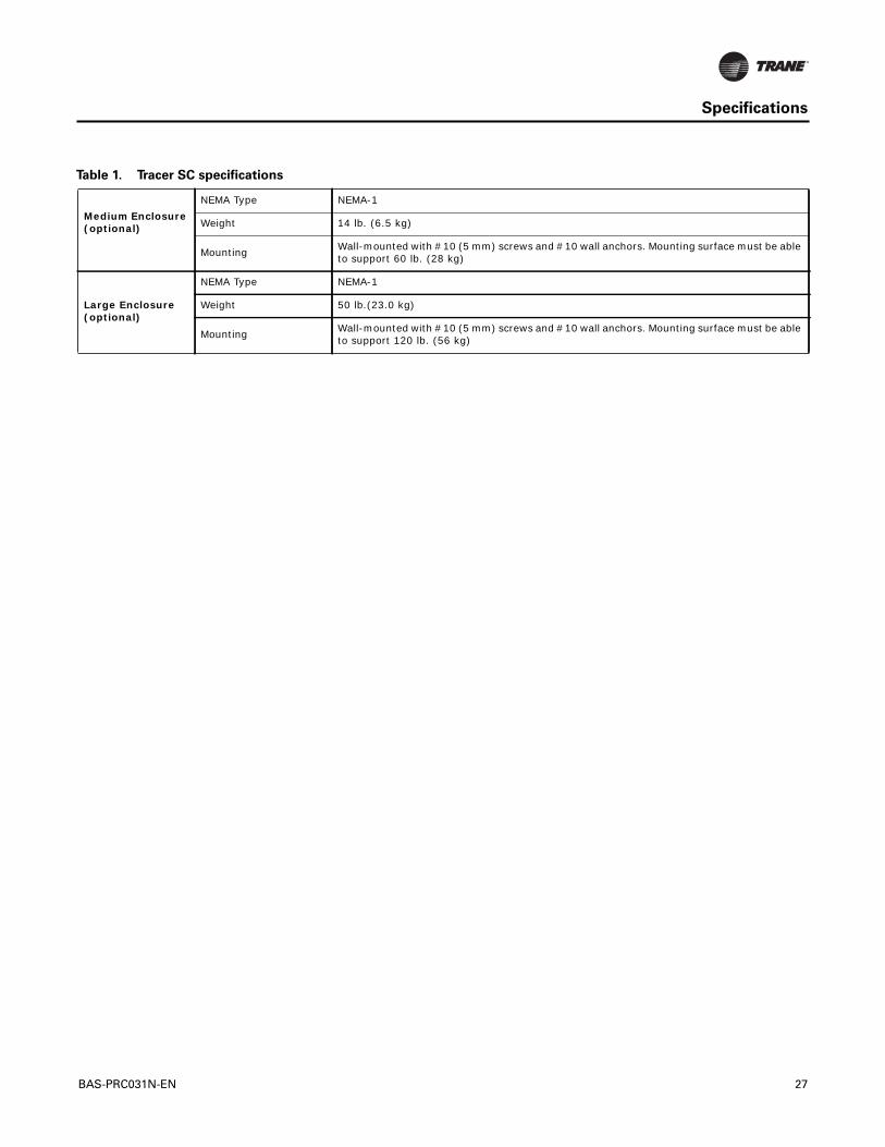
Table 1. Tracer SC specifications
Client Software Requirements
PC or Mac
Microsoft® Windows 7, 8:• Internet Explorer™ version 9.0 or higher• Mozilla Firefox® latest version • Google Chrome™ latest versionMac®OS :
• Mozilla Firefox® latest version • Google Chrome™ latest version • Safari® latest version
Tablet/Phone
iOS (iPad®/ iPhone®) latest version:• Safari (latest version)• Mozilla FireFox (latest version)• Google Chrome (latest version)Android (latest version)• Google Chrome (latest version)• Mozilla FireFox (latest version)Windows Mobile – (latest version)• Stock browser only
Concurrent Users • Five
Supported Languages
Up to four languages are supported per Tracer SC.• English• Chinese (Simplified/Traditional)• French • French Canadian• Portuguese (Brazil)• German• Indonesian• Japanese• Korean• Spanish (Latin America)• Thai• Polish• Arabic
BAS-PRC031N-EN 25

Specifications
Tracer SC system controller
Power requirements From PM014 Power Supply: 24 Vdc @ 0.3A; 14VA max (PM014 input VA)
Operating environment• Temperature: From –40°F to 122°F (–40°C to 50°C) • Relative humidity: From 10% to 90%, non-condensing
Storage environment • Temperature: From –40°F to 158°F (–40°C to 70°C) • Relative humidity: From 5% to 95%, non-condensing
Agency Listings
UL: • UL-864/UUKL listed (when installed and programmed in accordance with the Engineered
Smoke Control System Application Guide, BAS-APG019-EN) • UL-916-PAZX – energy management• CUL-C22.2-signal devices – Canada FCC:• FCC part 15, Class A CECE:• Emissions EN61326:1998 Class B• Immunity EN61326:1998• Commercial Safety EN61010-1:2001 ISO:• 9001:2008
Processor PowerPC405 Core
Memory• FLASH 400 MB• SDRAM 256 MB
Battery • No battery required. The clock is maintained for a minimum of three days by the super capacitor. All other programs are backed up by nonvolatile memory.
Protocol Communication
BACnet
Tracer building automation systems communicates with BACnet devices that support:• Communications based on the BACnet ASHRAE/ANSI 2012 standard • ENV-1805-1/ENV-13321-1• 10BASE-T/100BASE-TX dedicated Ethernet (ISO/IEC 8802-3) or Transmission Control
Protocol/Internet Protocol (TCP/IP) compatible networkTracer SC is listed by BACnet Test Labs (BTL) as a BACnet Building Controller (B-BC). Listing information can be found at: http://www.bacnetinternational.net
LonTalk
Tracer building automation systems communicates with LonTalk devices that support:• Communications based on the EIA-709.1 (LonTalk) standard• LonTalk standard network variable types (SNVTs)• FTT-10A or FT-X1 transceivers• Twisted-pair physical media (Level 4 wiring)
Device Limits
Tracer SC facility (Combination of all protocols)• Up to 240 devicesBACnet (Per link/Per facility)• Tracer UC200 Series - 60/240• Tracer UC400 Series - 60/240• Tracer UC600 Series- 10/20• Tracer UC800 Series - 60/240• BCI Series - 60/240• Trane Communicating Thermostats - 60/120• Non-Trane BACnet - 32/240LonTalk (Per link/Per facility)• AH Series - 120/120• CH Series - 120/120• VV Series - 120/120• ZN Series - 120/120 • MP503 - 120/120• MP580 - 20/20• Trane Communicating Thermostats - 120/120• Non-Trane LON - 120/120Air-Fi Wireless (Per network/per facility)• WCI - 30/240
Table 1. Tracer SC specifications
26 BAS-PRC031N-EN
Specifications
Medium Enclosure (optional)
NEMA Type NEMA-1
Weight 14 lb. (6.5 kg)
Mounting Wall-mounted with #10 (5 mm) screws and #10 wall anchors. Mounting surface must be able to support 60 lb. (28 kg)
Large Enclosure (optional)
NEMA Type NEMA-1
Weight 50 lb.(23.0 kg)
Mounting Wall-mounted with #10 (5 mm) screws and #10 wall anchors. Mounting surface must be able to support 120 lb. (56 kg)
Table 1. Tracer SC specifications
BAS-PRC031N-EN 27

Hardware Components
The SC system controller itself and additional hardware options are described in this section.
• Tracer SC system controller components
• Trane PM014 power supply module
• Tracer BACnet terminator
• Medium enclosure
• Large enclosure
Tracer SC System Controller
TheTracer SC system controller components are labeled in Figure 15.
Figure 15. Tracer SC system controller components
LonTalk
BACnet MS/TP LINK 1
BACnet MS/TP LINK 2
Status LED
Inter-module connector (IMC) for power
Inter-module connector (IMC) for power
BACnet LEDs
LonTalk LEDs
Power button
LonTalk service LED
LonTalk service pin
Ethernet LEDs
USB port for service tool connection
7-segment display
Rotary switches
SD card port
RS-232 serial connection (factory use only) Ethernet network connection 1
(supports BACnet and TCP/IP - recommended for building LAN connections)
Ethernet network connection (supports TCP/IP - recommended for direct connection to PC
USB host (future)
28 BAS-PRC031N-EN

Hardware Components
Dimensions
Trane PM014 Power Supply Module
TheTrane PM014 power supply module provides 24 Vdc forTrane inter-module communication(IMC) buses (Figure 17, p. 29). IMC buses are used in components ofTrane building automationsystems, including theTracer SC system controller. Refer to the “Power Supply ModuleInstallation, Operation, andTroubleshooting Guide”, BAS-SVX33.
Figure 16. Tracer SC system controller dimensions
5.65 in (143.6 mm)
2.40 in (60.8 mm)
1.93 in (49 mm)
4.00 in (101.6 mm)
Figure 17. PM014 power supply module (dimensions)
2424VACVAC
XFMRXFMROUTOUT2424VACVAC
4.0 in. (102 mm)
4.2 in. (107.6 mm)
2.4 in. (60.9 mm)
2.4in. (60.9 mm)
1.8 in. (45.7 mm)
BAS-PRC031N-EN 29
Hardware Components
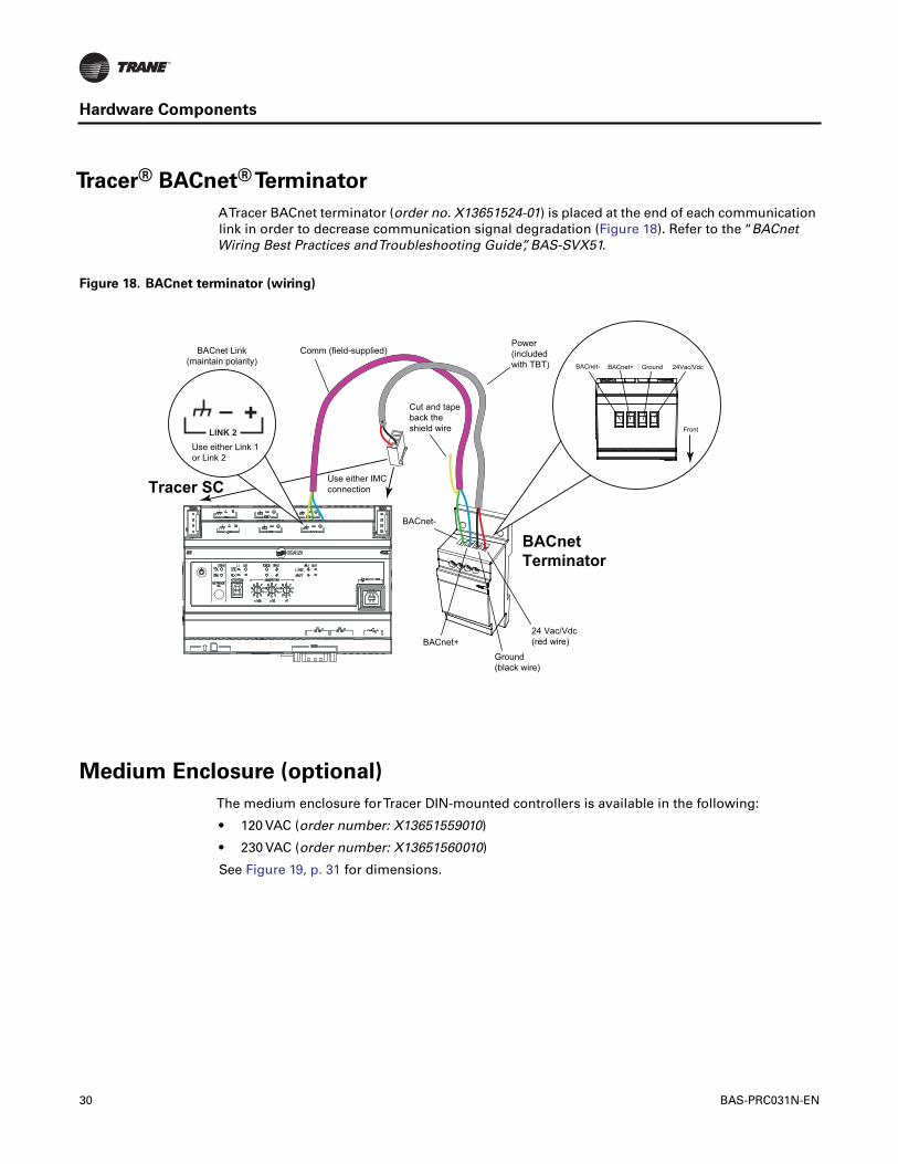
Tracer® BACnet® Terminator
ATracer BACnet terminator (order no. X13651524-01) is placed at the end of each communicationlink in order to decrease communication signal degradation (Figure 18). Refer to the “BACnetWiring Best Practices andTroubleshooting Guide”, BAS-SVX51.
Medium Enclosure (optional)
The medium enclosure forTracer DIN-mounted controllers is available in the following:
• 120 VAC (order number: X13651559010)
• 230 VAC (order number: X13651560010)
See Figure 19, p. 31 for dimensions.
Figure 18. BACnet terminator (wiring)
BACnet-
Use either IMCconnection
BACnet+
Tracer SC
BACnetTerminator
Ground(black wire)
Power(includedwith TBT)
Comm (field-supplied)
24 Vac/Vdc(red wire)
Cut and tapeback the shield wire
BACnet- BACnet+ Ground 24Vac/Vdc
FrontLINK 2
BACnet Link(maintain polarity)
Use either Link 1or Link 2
+–
30 BAS-PRC031N-EN
Hardware Components
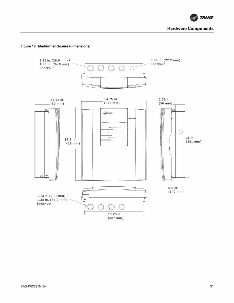
Figure 19. Medium enclosure (dimensions)
1.13 in. (28.6 mm) + 1.38 in. (34.9 mm) Knockout
0.88 in. (22.2 mm) Knockout
1.13 in. (28.6 mm) + 1.38 in. (34.9 mm) Knockout
14.75 in. (373 mm)
31.13 in. (80 mm)
2.25 in. (56 mm)
16.5 in. (418 mm)
15 in. (381 mm)
5.5 in. (140 mm)
13.25 in. (337 mm)
BAS-PRC031N-EN 31

Hardware Components
Large Enclosure (optional)
The large enclosure forTracer DIN-mounted controllers is available in the following:
• 120 VAC
– solid door (order number: X1365155201)
– display-capable door (order number: X1365155301)
• 230 VAC DualTransformer
– solid door (order number: X1365155401)
– display-capable door (order number: X1365155501)
Figure 20. Large enclosure (dimensions)
Knockouts for 0.75/1.0 in. (19/25 mm) conduits
Knockout for 19 mm (0.75 in.) conduit
24.4 in. (618.4 mm)
23.6 in. (600.4 mm)
28.8
in.
(732
.4 m
m)
29.1
in.
(732
.9 m
m)
4.2 in. (106.6 mm)
32 BAS-PRC031N-EN

Trane optimizes the performance of homes and buildings around the world. A business of Ingersoll Rand, the leader increating and sustaining safe, comfortable and energy efficient environments,Trane offers a broad portfolio of advancedcontrols and HVAC systems, comprehensive building services, and parts. For more information, visit www.Trane.com.
Trane has a policy of continuous product and product data improvement and reserves the right to change design and specifications without notice.
We are committed to using environmentally
conscious print practices that reduce waste.
© 2015Trane All rights reserved
BAS-PRC031N-EN 04 May 2015
Supersedes BAS-PRC031M-EN (28 Feb 2015)