tracking - boston university
TRANSCRIPT

Tracking
Xttpp →
from CDF
Tracking: Find charged particles in event and preciselymeasure the directions and magnitude of theirmomenta, that is, p.

Different Aspects of Tracking
Many different technologies are employed in tracking, such as,multi-wire proportional chambers (MWPC), drift chambers,time projection chambers (TPC), silicon strips, silicon pixels,emulsions, bubble chambers, etc.
Due to time limitations, I will mainly talk about drift chambers.
Due to time (and knowledge) limitations, I will concentrateon the physics of drift chambers (ignoring almostcompletely pattern recognition and track fitting).

Drift ChambersThis talk will focus on drift chambers.
ChargedParticle
E
++
++
+
+++
_
__
__
__
_3 cmforATLASMDT
Electrons “drift”towards wire atroughly constantspeed.Measuring timegives distance toabout 100µ.
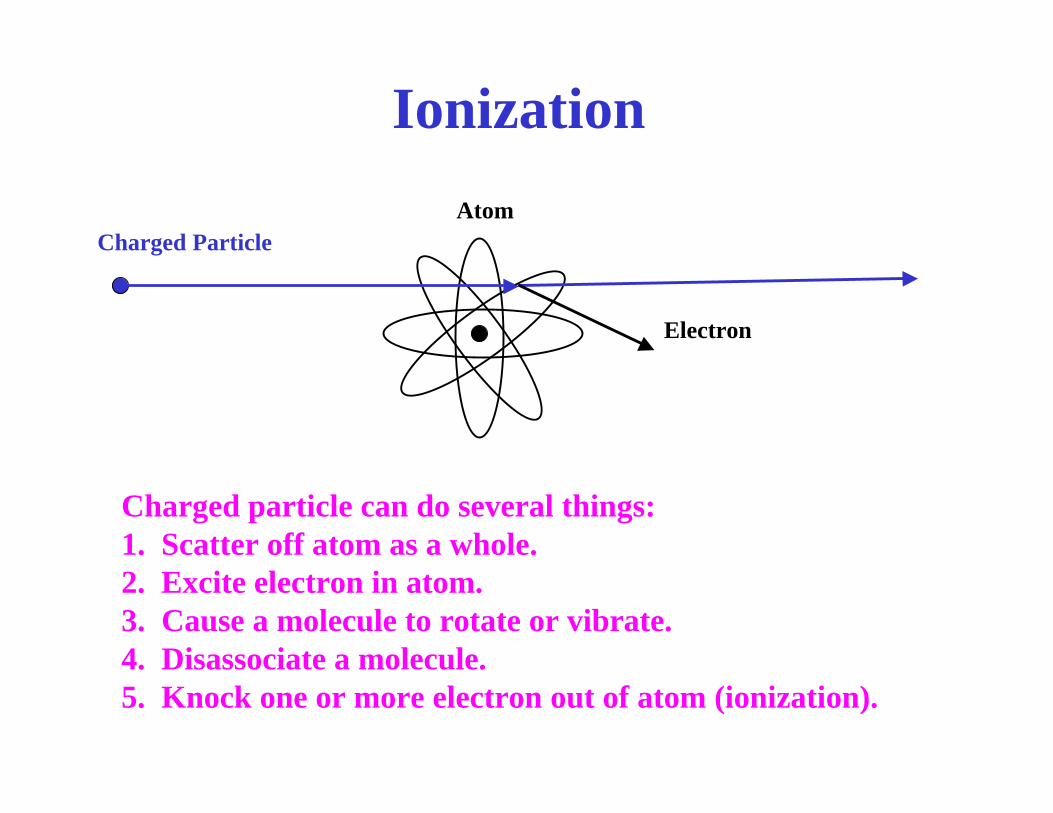
Ionization
Ionization
Charged Particle
Electron
Atom
Charged particle can do several things:1. Scatter off atom as a whole.2. Excite electron in atom.3. Cause a molecule to rotate or vibrate.4. Disassociate a molecule.5. Knock one or more electron out of atom (ionization).

Bethe-Bloch EquationTo get the rate of energy loss, we fold the fundamentalparticle-electron cross section with the propertiesof the atom (energy levels, number of electrons, etc.).
Bethe, Bloch, and others did this, giving the Bethe-Blochequation:
( )
βγδ−β−
γββ
ρπ−=2I
Tcm2ln
1z
AZ
cmrN4dxdE
22
max222
e21
222
e2e0
Avogadro
Classical electron radiusMax K.E. of e
Density Correction
Atomic mass
Atomic number
Mean excitation energy(188 eV for Argon)0.3071 Mev/g cm-2
Energy lostper unitlength
Note that dE/dx depends on fundamental constants, propertiesof the gas, and β.

Energy Loss
( )2cmg/MevdxdE1 −
ρ

Energy Loss II
( )2cmg/MevdxdE1 −
ρ
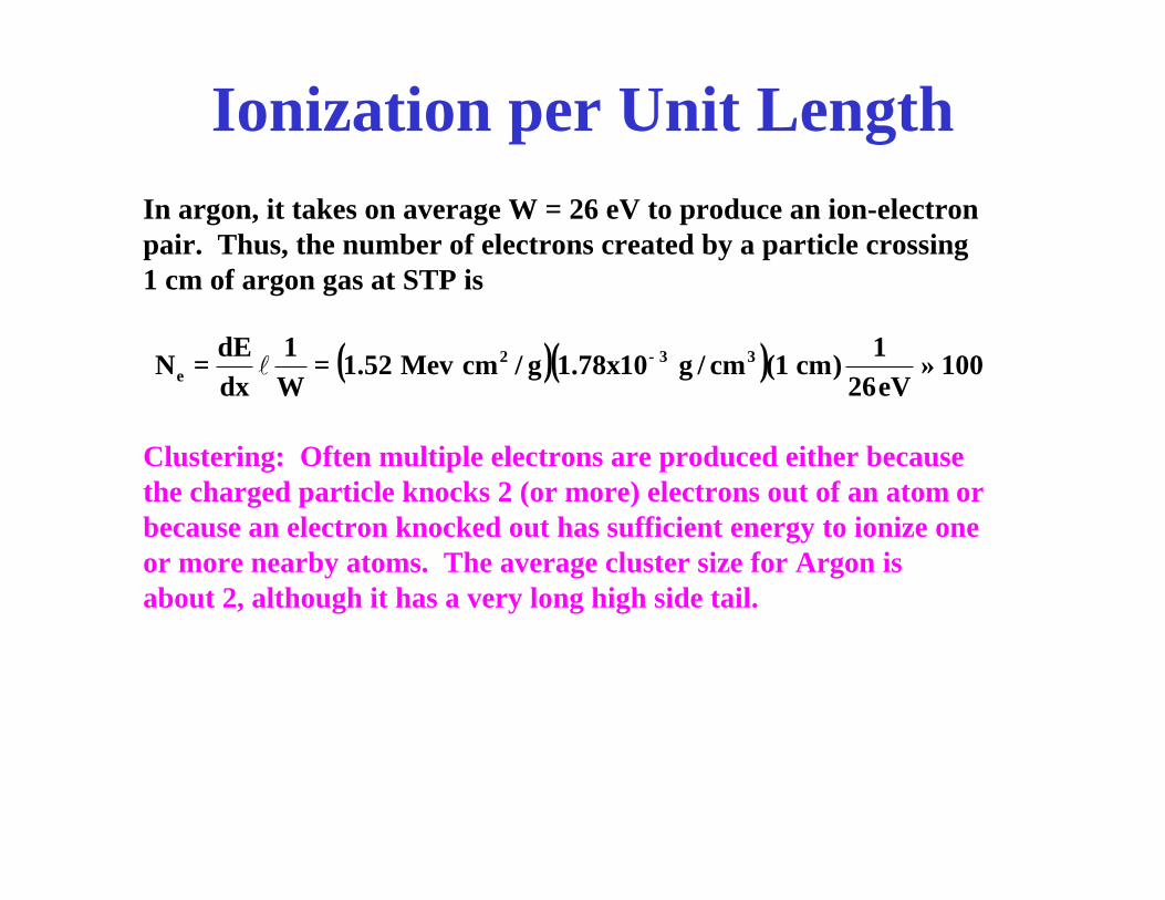
Ionization per Unit LengthIn argon, it takes on average W = 26 eV to produce an ion-electron pair. Thus, the number of electrons created by a particle crossing1 cm of argon gas at STP is
Clustering: Often multiple electrons are produced either because the charged particle knocks 2 (or more) electrons out of an atom or because an electron knocked out has sufficient energy to ionize one or more nearby atoms. The average cluster size for Argon isabout 2, although it has a very long high side tail.
( )( ) 100eV261
)cm1(cm/g10x78.1g/cmMev52.1W1
dxdE
N 332e ≈== −l

Delta RaysSometimes a particle knocks an electron outof the atom with sufficient energy to travel severalcentimeters or more.These electrons are known as delta rays.They can further ionize the gas - often in unwanted ways.
Particle
δ that gives time too early
δ that gives extra hits
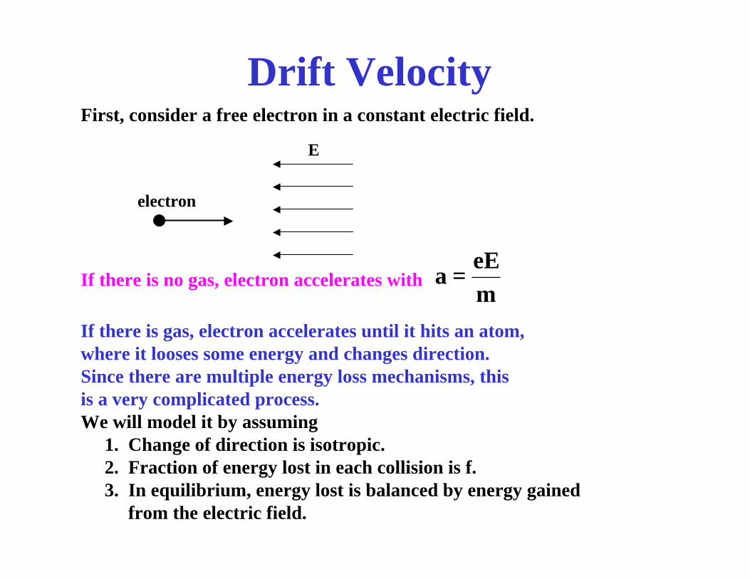
Drift VelocityFirst, consider a free electron in a constant electric field.
E
electron
If there is no gas, electron accelerates withmeE
a =
If there is gas, electron accelerates until it hits an atom,where it looses some energy and changes direction.Since there are multiple energy loss mechanisms, thisis a very complicated process.We will model it by assuming
1. Change of direction is isotropic.2. Fraction of energy lost in each collision is f.3. In equilibrium, energy lost is balanced by energy gained
from the electric field.

Drift Velocity Model
uvv ranrrr
+=electron
Atom τ = mean time between collisionsn = number density of atomsσ = cross sectionx = mean distance in drift
direction between collisionsf = fraction of energy lost per
collissionM = mass per moleculeρ = density
( )
( )
eEuxeEEux
mvfE
onacceleraticonstant meE
u
gain
221
lost
τ==τ=
=
τ=
E
Setting the energy lost equalto the energy gained, gives
2f
meEM
2f
mneE
u2
ρσ=
σ=
vran is random velocity due to scattering.u is the non-random component due to electric field.

Drift Velocity ExampleTypical numbers are E = 2 kV/cm and σ = 5x10-20 m2. We willtake standard temperature and pressure for the gas.
For Argon, electrons don’t have enough energy to excite atoms,so electrons “bounce” off entire atom, giving f ≈ 10-4. Plugginginto the formula gives u = 10 µ/ns.
For Methane, electrons in the relevant energy range can excitethe molecules (primarily rotation) giving f ≈ 10-2. Plugging into the formula gives u = 100 µ/ns.

Measured Drift VelocitiesArgon-Methane Argon-Ethane
Dri
ft V
eloc
ity
u (µ
/ns)
Dri
ft V
eloc
ity
u (µ
/ns)
Electric Field E (kV/cm) Electric Field E (kV/cm)
u = 85 µ/ns
u = 22 µ/ns
Note: dotted line for each mixture is 50 µ/ns.
100 % CH4
10 % CH4

Lorentz AngleIf there are both E and B fields, the electrons don’t “drift” along the E field.They drift an an angle ψ (known as the Lorentz angle).
EBelectron
ψ
An effective equation for the drift velocity is
where K represents the “friction” term.
uKBueEeFrrrrr
−×+=
In equilibrium, the total force is zero, giving , where u0 is thedrift speed when B = 0. E
Butan 0=ψ

Drift Distance vs Time (r-t) Relation
For real chambers, the electric field is seldom constant. Consider the drift tubes in the ATLAS muon system - they are tubes 3 cm in diameter, up to several meters long, with a 50 µm diameter gold-plated tungsten-rhenium wire down the center. The high voltage is 2.35 kV.
In cases like this (and more complicated ones), the relationship betweenthe drift distance and the drift time is normally determined experimentally.
Must be able to measure time that test particle passes through andthe position of the test particle in the drift tube.
This can be done with test beam, cosmic rays, or data from the experiment.

Measuring (r-t) Relation
Multilayersof tubes
Scintillators for triggeringand measuring time.
For each tube hit, fit track to other hits (to avoid bias) and determineposition in that tube. Get time from scintillators.

ATLAS MDT r-t Relation

DiffusionCollisions are a random process. Thus, if we start with an electron ata given position and let it drift, the distance covered in a given timewill have fluctuations. Consider a simple 1-d model in the drift direction where the mean free path is λ and the mean drift speed is u. Suppose in time t, the electronmakes N collisions.The probability P(l) of going a distance l between collisions is
( ) λ−
=l
ll e
1P
The variation in the distance traveled in N collisions is found by
( ) ( ) ( )2222
L
22222
i
2i
jiji
2
i
2i
jiji
jj
ii
2
N
1ii
N
1ii
NLL
NN2NNNL
L
NLL
λ=−=σ
λ+=λ+λ−=+=⇒
+==
λ==⇒=
∑∑
∑∑∑∑
∑∑
≠
≠
==
lll
lllll
ll
Diffusion II
2u
t2L
t2N
DDt2N2
22L
λ=
λ=
λ=⇒≡λ=σ
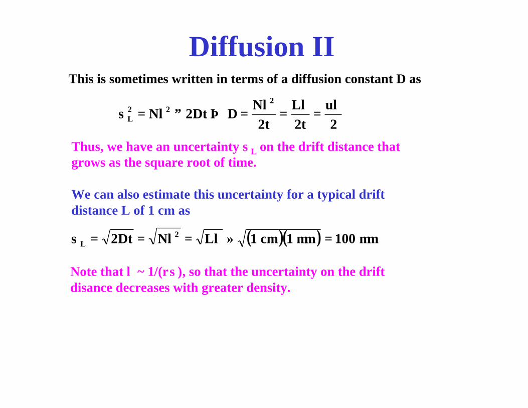
This is sometimes written in terms of a diffusion constant D as
Thus, we have an uncertainty σL on the drift distance thatgrows as the square root of time.
We can also estimate this uncertainty for a typical driftdistance L of 1 cm as
( )( ) m100m1cm1LNDt2 2L µ=µ≈λ=λ==σ
Note that λ ~ 1/(ρσ), so that the uncertainty on the driftdisance decreases with greater density.

AvalancheWhen drifting electrons get close to the wire, the electric field is high andthe electrons gain sufficient energy between collisions to ionize atoms/molecules.These ionization electrons can in turn further ionize the gas. This givesan exponentially increasing number of electrons.
Simple model: Avalanche starts when energy gained by driftingelectron between collision is e∆V = I0 (the ionization potentialof the atom). Each time the electrons pass through a potential change of ∆V, the number of electron doubles.
Gas Gain
where r0 is the radius at which avalanche starts. Let λ be the mean free path.
V)a(V)r(V 0
2G ∆−
=

Gas Gain
ρσ
=
ρσ
=
λ
=λ=∆=
ab
lnI
eVMr
ab
lnr
eVM
ab
lnr
eVeEVeI
0
0
0
For argon at STP with V = 2kV, I0 = 18 eV, and σ = 5 x 10-21 m2,r = 60 µm = 2.3 a.
( )
ρσ
==a/blnI
eVMln
)a/bln(I2lneV
I)r(eV
2lnGln000
0
Under the conditions we are assuming, G = 5 x 10⁵.
Note that G is roughly exponential in V and thatρρ∆
≈ρρ∆
=∆
12)a/bln(I
2lneVGG
0

Avalanche SimulationSimulation of an avalanche. The Note that it begins a few diameters from the wire and develops somewhat unevenly, but most of the avalanche is on one side. Also, the avalanche spreads a few diameters along the wire.
Matoba, et al., IEEE Trans. Nucl.Sci., NS-32, 541 (1985)

Signal Extraction
A rough schematics of a common signal electronics connection is shown.
HV BlockingCapacitor
ASD(amplifier,shaper,discriminator

Current due to image chargeElectrons from avalanche do not leave sense wireimmediately, even for ideal electronics.To see this, consider an avalanche near a groundedconducting sphere (for which I can do the calculations).
A
q-q
A
q
q’R
E
r’r
∞==−
=
−=′
r for 0 R r for q
rR
)r(ErqR
urqR
dtdr
rqR
dtqd
i 2ion22 µ−=−=−=′
−=
i
Note: signal depends on movement of positive ions.

Current Due To Image Charge IIA more careful treatment of the cylindrical case (based on energy and work methods) gives
)a(E2a
twherett
1
ab
ln
q)t(i 0
0 µ=
+
=
Note that the signal still depends on the positive ion motion.
For V = 2 kV, a = 25 µm, b = 1.5 cm, and typical = 1.5 cm2 V-1 s -1,t0 = 6.6 ns.

Signal Shape and DurationLook at i(t) and fraction of charge collected for q = 1 pC andt0 = 5 ns.

Space ChargeThe number of positive ions in an avalanche is comparableto the surface charge on the sense wire for a length ofa few diameters along the wire.
Thus, the local distortions of the electric field are significant.
Because of their low drift speeds and the long distances theymust drift to cathode, positive ions remain in the drift volumefor long times.
If the rate of particle passing through the drift cell ishigh enough, the cloud of positive ions that haven’tcleared (known as space charge) have significant detrimentaleffects on the performance.

AgeingHydrocarbon molecules struck by charged particles oravalanche electrons can ionize or disassociate.They makes them chemically active and they can formlonger chains.This gives long chain hydrocarbons that can “freeze out”onto the sense wires, adversely affecting performance.
C
H
H
H
H
particle
C
H
H
H
H C
H
H
H
H+
C
H
H
H
C
H
H
H
HH
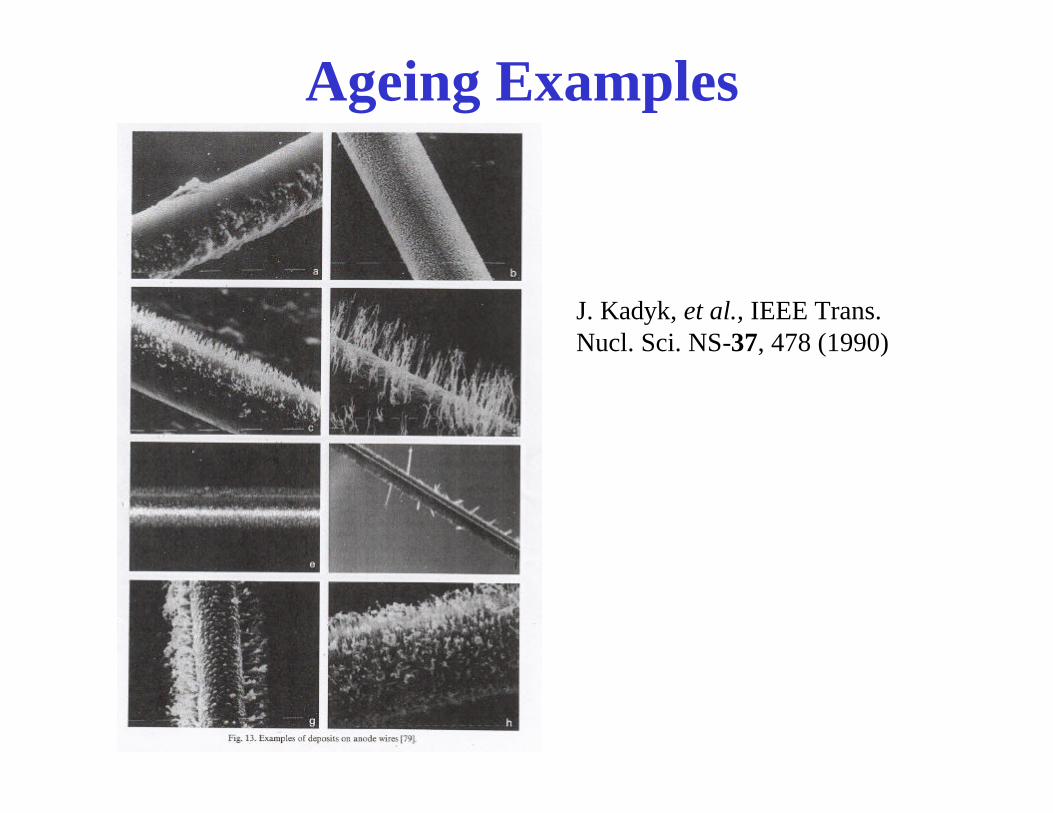
Ageing Examples
J. Kadyk, et al., IEEE Trans.Nucl. Sci. NS-37, 478 (1990)

Gas selectionSelection of gas is a compromise among many things:
1. Low electron affinity (noble gas)2. Large ionization (heavy noble gas)3. Cost (usually means people choose argon) 4. Must have quenching (methane, ethane, alcohol,
carbon dioxide, etc., etc., etc.)5. Drift velocity6. Resolution (diffusion)7. Lorentz angle8. Gas Gain9. Positive ion mobility10. Multiple scattering11. Ageing
Momentum Measurement
We want the direction and magnitude of the momentum.
The uncertainty on direction is usually less importantfor the physics (except for secondary vertex detection).
The uncertainty on the magnitude is determined bythe hit resolution (usually dominated by diffusion)and the relationship between the geometry andthe momentum.

Drift Direction
The best momentum resolution is obtained if
1. the drift direction is perpendicular to the track direction and
2. the drift direction is perpendicular to the B field.
Remember that the actual drift direction is given by the Lorentz
angle in addition to the E field.

Drift Chamber in Solenoidal Field
B
B is along beam direction (z).
Tracks are roughly radial.
We want direction in azimuthaldireciton.

Solenoidal Momentum Resolution
R
s
Bqp
R T=
L
Interaction point
sagitta
Solenoid
The resolution on PT is relatedto the resolution on s, which inturn is related to the hitresolution (~100 microns).
ATLAS has a 2 Tesla solenoidwith a radius of 1.25 m, givinga resolution of about 4% fora 100 GeV/c track.
4N720
qBLPs
qBLP
P8qBL
R8L
s
2s
2T
P
2
T
T
22
T +σ
=σ⇒
=⇒
==
Stat.factor
Alignment
In order to take advantage of resolution, we must know thelocation (at least relative) of all the wires to better thanthe resolution.
This is done with1. Precision construction2. Surveying3. Optical alignment (lasers, cameras, lenses)4. Lasers simulating tracks5. Tracks

Pattern Recognitionand Track Fitting
Pattern is recognition is the process of deciding which hits go on which tracks. It is often the most CPU intensive step in data reconstruction.
Track fitting is the process of determining the best estimate of the track parameters (for example, helix parameters in a solenoidal chamber) from a set of hits.
These are two very important and interesting topics,about which I will say nothing further, except thatmany of the tools used here are becoming usesfulin physics analyses, such as, Kalman filters, Hough transforms, and neural nets.

Example Track

ATLAS Detector

Part of the ATLAS Endcap Muon Chambers
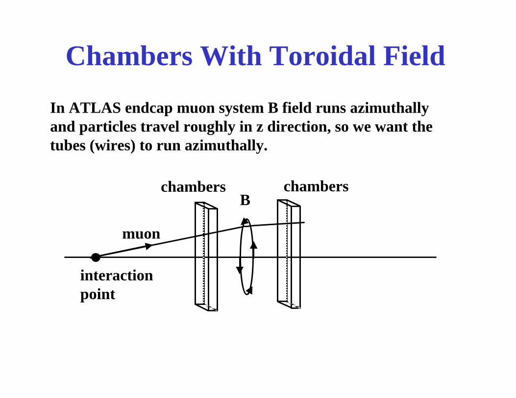
Chambers With Toroidal Field
In ATLAS endcap muon system B field runs azimuthally and particles travel roughly in z direction, so we want the tubes (wires) to run azimuthally.
Bchamberschambers
muon
interactionpoint

Resolution With Toroidal Field
Assume constantB out of page
B
R R
L
L
Assume N equal spaced hitsbefore and after B field.
Difference in slopes b of the two lines depends on p (and Band .
Let δs be the hit resolution.
l
l
N hits
N hits
θ
( )( )
Ls
N6
eBp
bbeB
p
beB
pbbbtan
peB
mveB
Rtan
2
2
12
δ=∆δ
∆=δ
∆=⇒∆≡−=θ
=γ
==θ
ll
l
lll
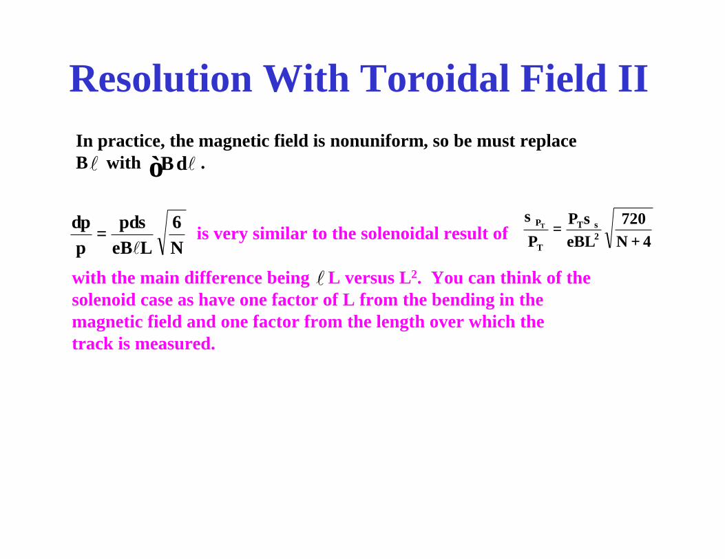
Resolution With Toroidal Field II
N6
LeBsp
pp
lδ
=δ
is very similar to the solenoidal result of 4N720
eBLP
P 2sT
T
PT
+σ
=σ
with the main difference being L versus L2. You can think of thesolenoid case as have one factor of L from the bending in themagnetic field and one factor from the length over which thetrack is measured.
l
In practice, the magnetic field is nonuniform, so be must replaceB with .l ∫ ldB

Conclusion
−+−+ µµµµ→→→ 00ZZHgg
Simulation of an eventin ATLAS detector.White lines are the fourmuons. The other tracksare due to particlesfrom quarks in protons.
Drift chambers are important tracking detectors. They are complexbut much about them can be understood with a few simple modelscontaining reasonable parameters.