traction power system requirements · any light rail system high voltage (hv) network, the traction...
TRANSCRIPT

S
uper
sede
d by
T L
R E
L 00
001
ST
v2.0
, 22/
12/2
017
Traction Power System Requirements
T LR EL 00001 ST
Standard
Version 1.0
Issued date: 25 May 2017
© State of NSW through Transport for NSW 2017

T LR EL 00001 ST Traction Power System Requirements
Version 1.0 Issued date: 25 May 2017
Sup
erse
ded
by T
LR
EL
0000
1 S
T v2
.0, 2
2/12
/201
7
Important message
This document is one of a set of standards developed solely and specifically for use on Transport Assets (as defined in the Asset Standards Authority Charter). It is not suitable for any other purpose. The copyright and any other intellectual property in this document will at all times remain the property of the State of New South Wales (Transport for NSW). You must not use or adapt this document or rely upon it in any way unless you are providing products or services to a NSW Government agency and that agency has expressly authorised you in writing to do so. If this document forms part of a contract with, or is a condition of approval by a NSW Government agency, use of the document is subject to the terms of the contract or approval. To be clear, the content of this document is not licensed under any Creative Commons Licence. This document may contain third party material. The inclusion of third party material is for illustrative purposes only and does not represent an endorsement by NSW Government of any third party product or service. If you use this document or rely upon it without authorisation under these terms, the State of New South Wales (including Transport for NSW) and its personnel does not accept any liability to you or any other person for any loss, damage, costs and expenses that you or anyone else may suffer or incur from your use and reliance on the content contained in this document. Users should exercise their own skill and care in the use of the document. This document may not be current and is uncontrolled when printed or downloaded. Standards may be accessed from the Asset Standards Authority website at www.asa.transport.nsw.gov.au
© State of NSW through Transport for NSW 2017

T LR EL 00001 ST Traction Power System Requirements
Version 1.0 Issued date: 25 May 2017
Standard governance
Owner: Lead Electrical Engineer, Asset Standards Authority
Authoriser: Chief Engineer, Asset Standards Authority
Approver: Executive Director, Asset Standards Authority on behalf of the ASA Configuration Control Board
Document history
Version Summary of changes
1.0 First issue
For queries regarding this document, please email the ASA at [email protected] or visit www.asa.transport.nsw.gov.au
© State of NSW through Transport for NSW 2017 S
uper
sede
d by
T L
R E
L 00
001
ST
v2.0
, 22/
12/2
017

T LR EL 00001 ST Traction Power System Requirements
Version 1.0 Issued date: 25 May 2017
Preface The Asset Standards Authority (ASA) is a key strategic branch of Transport for NSW (TfNSW).
As the network design and standards authority for NSW Transport Assets, as specified in the
ASA Charter, the ASA identifies, selects, develops, publishes, maintains and controls a suite of
requirements documents on behalf of TfNSW, the asset owner.
The ASA deploys TfNSW requirements for asset and safety assurance by creating and
managing TfNSW's governance models, documents and processes. To achieve this, the ASA
focuses on four primary tasks:
• publishing and managing TfNSW's process and requirements documents including TfNSW
plans, standards, manuals and guides
• deploying TfNSW's Authorised Engineering Organisation (AEO) framework
• continuously improving TfNSW’s Asset Management Framework
• collaborating with the Transport cluster and industry through open engagement
The AEO framework authorises engineering organisations to supply and provide asset related
products and services to TfNSW. It works to assure the safety, quality and fitness for purpose of
those products and services over the asset's whole-of-life. AEOs are expected to demonstrate
how they have applied the requirements of ASA documents, including TfNSW plans, standards
and guides, when delivering assets and related services for TfNSW.
Compliance with ASA requirements by itself is not sufficient to ensure satisfactory outcomes for
NSW Transport Assets. The ASA expects that professional judgement be used by competent
personnel when using ASA requirements to produce those outcomes.
About this document
The purpose of this document is to set out the requirements for the configuration and
performance of traction power systems for light rail.
This standard is a first issue.
© State of NSW through Transport for NSW 2017 Page 4 of 46 S
uper
sede
d by
T L
R E
L 00
001
ST
v2.0
, 22/
12/2
017

T LR EL 00001 ST Traction Power System Requirements
Version 1.0 Issued date: 25 May 2017
Table of contents 1. Introduction .............................................................................................................................................. 7
2. Purpose .................................................................................................................................................... 7 2.1. Scope ..................................................................................................................................................... 7 2.2. Application ............................................................................................................................................. 8 3. Reference documents ............................................................................................................................. 8
4. Terms and definitions ........................................................................................................................... 10
5. Traction power system fundamentals ................................................................................................. 12
6. Traction power system capacity .......................................................................................................... 12 6.1. Traction power system capacity requirements .................................................................................... 12 6.2. Traction power demand modelling ...................................................................................................... 13 7. Traction power stray current minimisation and mitigation – light rail system assets ................... 14 7.1. Earthing of running rails ....................................................................................................................... 14 7.2. Monitoring of track insulation ............................................................................................................... 15 7.3. Load sharing by rectifiers ..................................................................................................................... 15 7.4. Stray current collection mesh .............................................................................................................. 15 7.5. Track insulation resistance .................................................................................................................. 16 7.6. Embedded track systems .................................................................................................................... 17 7.7. Electrical configuration of track slab reinforcing .................................................................................. 18 7.8. Separation of earthing systems ........................................................................................................... 18 8. Traction power stray current minimisation and mitigation – utility assets ..................................... 19 8.1. Utility asset configuration ..................................................................................................................... 19 8.2. Interference limits for non-cathodically protected assets .................................................................... 19 8.3. Interference limits for cathodically protected assets ............................................................................ 20 8.4. Measurement protocol ......................................................................................................................... 20 8.5. Monitoring ............................................................................................................................................ 20 8.6. Active mitigation devices ..................................................................................................................... 21 9. Earthing, bonding, stray direct current and lightning protection .................................................... 21 9.1. Principles document ............................................................................................................................ 21 9.2. Design documentation ......................................................................................................................... 21 9.3. Alternating current earthing ................................................................................................................. 22 9.4. Lightning protection ............................................................................................................................. 25 9.5. Direct current bonding system ............................................................................................................. 26 10. Traction power reliability, availability, maintainability and safety ................................................... 27 10.1. Traction power reticulation system robustness ............................................................................... 27 10.2. Direct current touch voltages ........................................................................................................... 27 10.3. High voltage system fault levels ...................................................................................................... 27 10.4. Ambient conditions .......................................................................................................................... 27 10.5. Electrical protection ......................................................................................................................... 27 10.6. Voltage limiting device study ........................................................................................................... 28 10.7. Hazard log........................................................................................................................................ 28 10.8. Public awareness and advertising of new works ............................................................................. 29 11. Traction power electromagnetic compatibility ................................................................................... 30
12. Electrical safety system ........................................................................................................................ 32
© State of NSW through Transport for NSW 2017 Page 5 of 46 S
uper
sede
d by
T L
R E
L 00
001
ST
v2.0
, 22/
12/2
017

T LR EL 00001 ST Traction Power System Requirements
Version 1.0 Issued date: 25 May 2017
13. Management of work around light rail infrastructure ........................................................................ 32
14. Power quality ......................................................................................................................................... 34
15. Energy use ............................................................................................................................................. 34 16. Operations Control Centre ................................................................................................................... 34 16.1. Operations Control Centre functionality and performance relating to traction power system ......... 34 16.2. Operations Control Centre general and non-traction power system requirements ......................... 35 16.3. Electrical supervisory control and data acquisition system ............................................................. 35 17. Documentation, labelling and records ................................................................................................ 36 Appendix A Track insulation resistance test method (normative) .................................................... 37 A.1. Relationship to EN 50122-2 test method ............................................................................................. 37 A.2. Test method ......................................................................................................................................... 37 A.3. Readiness review ................................................................................................................................ 39 A.4. Rail resistance ..................................................................................................................................... 39 A.5. Placement of the voltage reference electrode (half-cell) (Ev) ............................................................. 39 A.6. Placement of the current injection reference electrode (EI) ................................................................ 40 A.7. Measuring equipment .......................................................................................................................... 40 A.8. Calculation ........................................................................................................................................... 40 A.9. Error study ........................................................................................................................................... 41 A.10. Safety ............................................................................................................................................... 41 Appendix B Example track insulation resistance test calculation (informative) ............................. 42
Appendix C Non-cathodically protected structures ............................................................................ 43
Appendix D Cathodically protected structures ................................................................................... 44 D.1. Structure categories ............................................................................................................................. 44
© State of NSW through Transport for NSW 2017 Page 6 of 46 S
uper
sede
d by
T L
R E
L 00
001
ST
v2.0
, 22/
12/2
017

T LR EL 00001 ST Traction Power System Requirements
Version 1.0 Issued date: 25 May 2017
1. Introduction The traction power system for a light rail system is essential to the reliable and effective
operation of the light rail service. Electric power is drawn from the electricity network,
transformed to the traction voltage level and reticulated for use by the light rail vehicles (LRVs).
The traction voltage level is sufficient that contact by persons will cause serious injury or death
and the traction voltage is reticulated in the public domain using bare conductors with which the
LRVs make contact. Accordingly, it is essential that a light rail traction power system is
configured and operated to ensure the safety of persons.
The traction current is direct current (dc) and so any 'stray current' might give rise to electrolytic
corrosion of buried metallic assets near the light rail system. Accordingly, it is essential that a
light rail traction power system is configured and operated to ensure that the integrity of buried
metallic assets is not compromised. This principle applies to light rail system assets, other
TfNSW assets and the assets of other parties including utilities.
2. Purpose The purpose of this document is to set out the requirements for the function, configuration and
performance of traction power systems for light rail on a whole of system basis. Associated
system-level procedural requirements are also set out in this document.
2.1. Scope This document applies to traction power systems for light rail as integrated systems, including
any light rail system high voltage (HV) network, the traction power substations and the traction
power reticulation system. This document specifies high-level requirements that apply across all
elements of the traction power system.
Specific requirements for supplying HV networks are set out in T LR EL 00002 ST High Voltage
Supply.
Specific requirements for light rail system HV networks are set out in T LR EL 00003 ST High
Voltage Network.
Specific requirements for traction power substations are set out in T LR EL 00004 ST Traction
Power Substations.
Specific requirements for dc traction power reticulation are set out in T LR EL 00005 ST Direct
Current Traction Power Reticulation.
Specific requirements for non-traction power supplies are set out in T LR EL 00006 ST Non-
Traction Power Supplies.
© State of NSW through Transport for NSW 2017 Page 7 of 46 S
uper
sede
d by
T L
R E
L 00
001
ST
v2.0
, 22/
12/2
017

T LR EL 00001 ST Traction Power System Requirements
Version 1.0 Issued date: 25 May 2017
Specific requirements for traction power supply infrastructure and LRV interface requirements
are set out in T LR EL 00007 ST Traction Power Supply Infrastructure and Light Rail Vehicle
Interface Requirements.
2.2. Application The requirements of this document apply to new and altered light rail system infrastructure.
Unless otherwise stated, application is not retrospective to existing infrastructure that is not
otherwise being altered.
This standard is intended to be used by Authorised Engineering Organisations (AEOs) that
undertake work on traction power systems for light rail.
3. Reference documents The following documents are cited in the text. For dated references, only the cited edition
applies. For undated references, the latest edition of the referenced document applies.
International standards
EN 12954:2001 Cathodic Protection of buried or immersed metallic structures – General
principles and application for pipelines
EN 13509 Cathodic Protection Measurement Techniques
EN 50121 (all parts) Railway applications - Electromagnetic compatibility
EN 50122-1:2011 Railway applications - Fixed installations – Electrical safety, earthing and the
return circuit – Part 1: Protective provisions against electric shock
EN 50122-2:2010 Railway applications – Fixed installations – Electrical safety, earthing and the
return circuit – Part 2: Provisions against the effects of stray currents caused by d.c. traction
systems
EN 50162:2004 Protection against corrosion by stray current from direct current systems
IEC 60850 Railway applications – Supply voltages of traction systems
Australian standards
AS 2067:2016 Substations and high voltage installations exceeding 1 kV a.c.
AS 2832 (all parts) Cathodic protection of metals
AS 4292.1 Railway safety management, Part 1: General requirements
AS/NZS 61000.6.3 Electromagnetic compatibility (EMC) – Part 6.3: Generic standards –
Emission standard for residential, commercial and light-industrial environments
© State of NSW through Transport for NSW 2017 Page 8 of 46 S
uper
sede
d by
T L
R E
L 00
001
ST
v2.0
, 22/
12/2
017

T LR EL 00001 ST Traction Power System Requirements
Version 1.0 Issued date: 25 May 2017
AS 62271.202 High-voltage switchgear and controlgear – Part 202: High-voltage/low-voltage
prefabricated substation
AS 7722:2016 EMC Management
AS 7722:2016 is an Australian RISSB standard
AS/NZS 1768 Lightning protection
AS/NZS 3835 (all parts) Earth potential rise – Protection of telecommunications network users,
personnel and plant
AS/NZS 4853 Electrical hazards on metallic pipelines
AS/NZS 7000 Overhead line design
AS/NZS 3000 Electrical installations (known as the Australian/New Zealand Wiring Rules)
AS/NZS 60479.1 Effects of current on human beings and livestock – Part 1: General aspects
Transport for NSW standards
EP 00 00 00 13 SP Electrical Power Equipment – Design Ranges of Ambient Conditions
EP 12 20 00 01 SP Bonding of Overhead Wiring Structures to Rail
EP 19 00 00 02 SP Protection System Requirements for the High Voltage Network
T MU TE 81002 ST Telecommunication Equipment – Network Management
T LR EL 00002 ST High Voltage Supply
T LR EL 00003 ST High Voltage Network
T LR EL 00004 ST Traction Power Substations
T LR EL 00005 ST Direct Current Traction Power Reticulation
T LR EL 00006 ST Non-Traction Power Supplies
T LR EL 00007 ST Traction Power Supply Infrastructure and Light Rail Vehicle Interface
Requirements
T MU HF 00001 ST Human Factors Integration – General Requirements
T MU TE 61007 ST Time Synchronisation of Industrial Automation and Control Systems,
version 1.0
Other reference documents
Energy Networks Association, ENA EG1 - 2006 Substation Earthing Guide
Energy Networks Australia, ENA Doc 001-2008 National Electricity Network Safety Code
© State of NSW through Transport for NSW 2017 Page 9 of 46 S
uper
sede
d by
T L
R E
L 00
001
ST
v2.0
, 22/
12/2
017
T LR EL 00001 ST Traction Power System Requirements
Version 1.0 Issued date: 25 May 2017
NSW Government, Department of Water and Energy (now NSW Department of Industry,
Division of Resources and Energy), Code of Practice – Electricity Transmission and Distribution
Asset Management
NSW Electrolysis Committee 1990, Guide for Measurement of Interference Caused by Cathodic
Protection and Railway Drainage Systems (the red book)
UK Office of Rail Regulation, Tramway Technical Guidance Note 3, Design Standards Stray
Current Management
4. Terms and definitions The following terms and definitions apply in this document:
ac alternating current
APS aesthetic power system (proprietary Alstom term)
dc direct current
DCCB direct current circuit breaker
double point indication separate SCADA indications of the fully open state, and the fully
closed state (relates to 'double-point information' as defined in AS 60870.1.3)
EMC electromagnetic compatibility
EPR earth potential rise
EVMC electric vehicle maintenance centre; a maintenance centre for light rail vehicles including
any of: maintenance area; cleaning area; vehicle exterior wash; wheel lathe. It may also include
a stabling area. However, a stabling area alone does not constitute an EVMC.
feeder circuit status evaluator equipment that continuously monitors and reports via SCADA
the status of a 750 V dc feeder as: live, safe to rail connect, dead or rail connected
HV high voltage
I2t the product of current squared and time (proportional to the energy dissipated in a
resistance)
LPS lightning protection system
LRV light rail vehicle
LV low voltage
OCC Operations Control Centre
OHW overhead wiring
OLE overhead line equipment
© State of NSW through Transport for NSW 2017 Page 10 of 46 S
uper
sede
d by
T L
R E
L 00
001
ST
v2.0
, 22/
12/2
017

T LR EL 00001 ST Traction Power System Requirements
Version 1.0 Issued date: 25 May 2017
overhead conductor system (OCS) the set of infrastructure required to connect the traction
power feeder cables to the LRV pantograph, including:
• OLE systems
• rigid conductor rail systems
quiescent potential the average potential between a buried asset and the reference half-cell at
a time when no LRVs are operating
RMS Roads and Maritime Services
RTU remote terminal unit
SCADA supervisory control and data acquisition
supplying HV network an electricity network that supplies electricity to a light rail system at
high voltage
(effective) touch voltage (Ute) voltage between conductive parts when touched simultaneously
by a person or an animal
Note 1: The value of the effective touch voltage can be appreciably influenced by the
impedance of the person or the animal in electric contact with these conductive parts.
Note 2: The conductive path through the body is conventionally from hand to both feet
(horizontal distance of 1 m) or from hand to hand.
(as defined in IEC 60050-195-05-11)
TPS traction power substation
traction power reticulation system the set of infrastructure required to connect the traction
power substations to the light rail vehicles, including the following:
• traction power feeder cables
• overhead conductor system
• segmented third rail system
• traction return conductors
The traction power reticulation system excludes all aspects of the running rails except only so
far as they function as traction return conductors.
traction power system the set of infrastructure required to convert the incoming supply from
the supplying HV network to the traction voltage and deliver that supply to the light rail vehicles.
This includes the following:
• traction power substations
• traction power reticulation system
© State of NSW through Transport for NSW 2017 Page 11 of 46 S
uper
sede
d by
T L
R E
L 00
001
ST
v2.0
, 22/
12/2
017

T LR EL 00001 ST Traction Power System Requirements
Version 1.0 Issued date: 25 May 2017
TRAD transformer-rectifier assisted drainage
TT Terra-Terra (earthing system)
VLD voltage limiting device
5. Traction power system fundamentals This section sets out the fundamental features of light rail traction power systems for the
purposes of standardisation and consistency with light rail systems already established in NSW.
The traction power system shall be a 750 V dc nominal system in accordance with IEC 60850
Railway applications – Supply voltages of traction systems.
The negative return for the traction power system shall normally be through the running rails.
Negative return cables in parallel with the running rails are permitted where required to reduce
voltage drop.
In a wire-free area where traction return from the LRVs is not required, the negative return may
be carried in cables only.
The negative rail-to-earth voltage at any point on a light rail system shall not exceed a level that
results in the effective touch voltage exceeding the maximum permissible level allowed in
accordance with EN 50122-1:2011.
Note: EN 50122-1:2011 includes a special limit applying to workshops and similar
locations.
The negative rail to earth voltage at the traction power substations shall be limited to a
maximum of 60 V. Under contingency conditions, a higher negative rail to earth voltage at a
traction power substation may be permissible subject to a satisfactory safety case and analysis
demonstrating that cascade tripping of traction power substation (TPS) voltage limiting devices
(VLDs) will not occur – see Section 10.6 for further information. In any case, the negative rail to
earth voltage at the traction power substations shall not exceed the maximum permissible
effective touch voltage allowed in accordance with EN 50122-1:2011.
6. Traction power system capacity 6.1. Traction power system capacity requirements
The traction power system shall have sufficient capacity to support the nominated proposed
service level in a defined area with a defined passenger loading, under the nominated
contingencies, with appropriate provision made for future extension from any nominated
terminus.
The supplying HV network is an electricity network that supplies electricity to a light rail system
at HV. The supplying HV network shall have sufficient capacity to support the nominated © State of NSW through Transport for NSW 2017 Page 12 of 46 S
uper
sede
d by
T L
R E
L 00
001
ST
v2.0
, 22/
12/2
017

T LR EL 00001 ST Traction Power System Requirements
Version 1.0 Issued date: 25 May 2017
proposed service level in a defined area with a defined passenger loading, under the nominated
contingencies, with appropriate provision made for future extension from any nominated
terminus.
Capacity planning shall be undertaken having cognisance of the practical implementation in
which capacity comes in coarse-sized discrete blocks. Incremental increases are
disproportionately costly and so it is prudent to make provision for foreseeable future increase in
demand. Accordingly, it may be appropriate that the service level used for determining the
required capacity of the traction power system is the service level for some future time rather
than the 'day one' service level.
6.2. Traction power demand modelling The traction power system infrastructure shall be sized based on traction system modelling
including computer-generated simulations of the electrical system using proven traction power
system software. The model shall be based on information for the vertical alignment and LRV
characteristics – any changes to this shall be reflected in updates to the traction power demand
modelling and resulting report. The modelling shall test the adequacy of the proposed traction
power system infrastructure elements in relation to at least the following factors:
• thermal capacity of each element, having appropriate regard to the thermal time-constant
of that element
• LRV voltage
• rail to earth voltage
• an appropriate margin between safe electrical protection settings for the 750 V dc feeders
and the maximum traction load on each feeder
The model shall confirm TPS capacity, location, average power demand and peak power
demand.
The model shall quantify the total energy consumption per hour for both peak and non-peak
operations. It shall also quantify the total braking energy lost per hour on board the LRVs as
heat for both peak and non-peak operations, that is, the total energy lost as heat in the friction
brakes or in the rheostatic braking resistors, which could not be recovered by regenerative
braking.
The model shall analyse negative rail potentials for the entire alignment, focusing on touch
potentials for areas within 2 m of the traction return rails as required by EN 50122-1:2011.
The modelling shall be undertaken for the following:
• conditions of maximum design passenger loading in the peak direction and a lesser agreed
passenger loading in the contra-peak direction
© State of NSW through Transport for NSW 2017 Page 13 of 46 S
uper
sede
d by
T L
R E
L 00
001
ST
v2.0
, 22/
12/2
017

T LR EL 00001 ST Traction Power System Requirements
Version 1.0 Issued date: 25 May 2017
• the most onerous design ambient conditions
• non-conservative driver behaviour, up to the constraints imposed by the technical systems
The traction power model shall utilise the final rail alignment, LRV performance and
characteristic details and shall make allowance for the intended level of signal priority. The
model shall include operation in all required contingencies, such as any single TPS being
offline. The analysis shall consider perturbations in operation to ensure that the traction power
reticulation system has the capacity to supply foreseeable coincident peak demands from
multiple LRVs.
Any load-flow study for the HV alternating current (ac) system shall be based upon the worst-
case direct current (dc) system loading.
After LRV operations commence, measurements shall be undertaken to validate the
assumptions in the model regarding the electrical load for the auxiliaries on the LRVs, the
traction loads and the regenerative braking current.
7. Traction power stray current minimisation and mitigation – light rail system assets
7.1. Earthing of running rails The traction power system for the main lines shall be 'unearthed' to minimise stray current in
accordance with EN 50122-2:2010 Railway applications – Fixed installations - Electrical safety,
earthing and the return circuit -- Part 2: Provisions against the effects of stray currents caused
by d.c. traction systems. There shall be no intentional connection to earth potential under
normal operating conditions.
The traction power system for an electric vehicle maintenance centre (EVMC) shall be either
'unearthed' or 'earthed'.
An 'earthed' system is permissible for an EVMC only if it does not cause the main line rails to be
earthed under normal conditions (except as LRVs transit insulated rail joints). Under degraded
mode (rectifier outage), it is permissible for the main line rails to be earthed for up to eight hours
per year to allow the EVMC to be fed from the main line system, subject to there being no
unacceptable stray current electrolysis corrosion impact on third party buried assets.
Insulated rail joints separating earthed and unearthed traction power systems shall not be
located where LRVs are expected to remain stationary.
The traction power system shall be configured such that the traction return earthing, bonding
and isolation complies with the specific requirements of EN 50122-2:2010 and AS 2832 (all
parts) Cathodic protection of metals relating to the control and mitigation of stray currents.
© State of NSW through Transport for NSW 2017 Page 14 of 46 S
uper
sede
d by
T L
R E
L 00
001
ST
v2.0
, 22/
12/2
017
T LR EL 00001 ST Traction Power System Requirements
Version 1.0 Issued date: 25 May 2017
7.2. Monitoring of track insulation The rail to earth voltage at an appropriate set of locations shall be continuously monitored and
interpreted to alert the operator to changed conditions indicative of increased levels of stray
current. This system shall be designed to provide early warning of emerging stray current
issues, providing the opportunity for intervention before the situation becomes problematic for
the utility asset operators.
7.3. Load sharing by rectifiers Traction rectifiers shall be configured to minimise load sharing by rectifiers not immediately
adjacent to the section within which the load current is being drawn. This is required to reduce
the average longitudinal voltage in the rail and so reduce the voltage driving stray current.
7.4. Stray current collection mesh A stray current collection mesh shall not be used.
Note: Not using a stray current collection mesh is consistent with Tramway Technical
Guidance Note 3, 'Design Standards Stray Current Management' Section 9a,
published by the UK Office of Rail Regulation.
http://orr.gov.uk/__data/assets/pdf_file/0012/5070/TTGN3.pdf.
Where steel meshes or similar reinforcement are used as part of the track form for structural
reasons or as a crack control measure then the light rail design team shall review whether this
should continue to be electrically connected. However, in that case they shall not be connected
to the traction return circuit. Detailed specifications and design for this shall be developed during
the design of the track forms.
Connection of the steel reinforcement to the negative bus at the substation will encourage a
significantly greater stray current flow from the rails as compared to allowing the steel
reinforcement to remain isolated from the negative bus. The steel reinforcement is then termed
a stray current collection system as it will encourage stray currents to flow in it and return to the
substation through a stray current collector cable as compared to flowing in the general mass of
earth or via other less conductive paths bonded to the rail.
Reinforcing should not be used to collect stray current and return this to the substation negative.
Note: This does not preclude the use of a mesh (in the form of the reinforcing steel or
otherwise) to monitor stray current or for use in locating track insulation faults. These
uses of the reinforcing are entirely appropriate, and even necessary, and are not
precluded by the requirements of this section.
The issue with a stray current collection mesh is that it will not only intercept stray current
flowing out from the rails, it will also provide a much improved path for stray current from the soil
© State of NSW through Transport for NSW 2017 Page 15 of 46 S
uper
sede
d by
T L
R E
L 00
001
ST
v2.0
, 22/
12/2
017

T LR EL 00001 ST Traction Power System Requirements
Version 1.0 Issued date: 25 May 2017
to return to the substation negative. It is not possible to create a mesh that will collect current
from its upper surface only.
The use of a stray current collection mesh, especially where the stray current collection mesh is
not in its entirety under the tracks, is to reduce the loop resistance for the stray current path and
so increase the magnitude of the stray current. This effect might be significantly diminished
where there is complete cover by the mesh except for the situation at substations – either the
mesh is discontinuous at the substations in which case there will be potential differences and
current will flow between the two sections of mesh via the soil, or the mesh will be continuous in
which case current will flow between substations via the mesh, leading to voltage drop along the
mesh and again potentially driving stray current as the mesh is far less well insulated from the
soil than the rail is.
To minimise stray current flow in normal service, this stray current collection system is to be
operated normally open and it shall be specified in the operational instructions to be operated
closed for short periods as is necessary to fault find or proactively maintain the traction system.
7.5. Track insulation resistance The track insulation resistance acceptance criteria for 'unearthed' track (two rails) shall be not
less than 10 Ω·km. The track insulation resistance acceptance criteria shall be greater than
10 Ω·km to the extent required to ensure that the level of stray current interference on buried
assets does not exceed the agreed limits without any need for restrictions on regenerative
braking by LRVs, and without the use of active mitigation devices.
Note: see Section 8.6 regarding active mitigation devices.
In establishing the track insulation resistance acceptance criteria for commissioning and
re-commissioning, the designer shall make allowance for degradation and contamination so that
the projected long-term track insulation resistance shall meet the requirement set out in this
section.
The measured track insulation resistance shall not be less than the established track insulation
resistance acceptance criteria.
The track insulation resistance shall be measured inclusive of all circuits normally connected to
the rails or traction return circuit in the length of track under test connected as they would
normally be.
Track insulation resistance may be measured under 'dry' conditions. Special drying processes in
preparation for the test shall not be used.
Normal maintenance cleaning may be undertaken prior to the test. Special cleaning processes
and the application of substances such as water repellents prior to the test shall not be used.
© State of NSW through Transport for NSW 2017 Page 16 of 46 S
uper
sede
d by
T L
R E
L 00
001
ST
v2.0
, 22/
12/2
017

T LR EL 00001 ST Traction Power System Requirements
Version 1.0 Issued date: 25 May 2017
The track insulation resistance shall be measured in accordance with the test method set out in
Appendix A (normative).
7.6. Embedded track systems
7.6.1. Type approval The embedded track system forms a significant portion of the light rail infrastructure, has a
relatively long asset life, and is not easily replaced. Accordingly, the track insulation system for
embedded track shall be an ASA type approved system.
Guidance for type approval is given in T MU MD 00005 GU Type Approval of Products.
Type approval for the track insulation system shall be obtained from ASA before track system
materials (rails, track insulation and so on) are ordered, and before detailed design is
progressed based on a specific track insulation system. Due to the cost and schedule
implications, it is not appropriate to proceed at risk.
For any boot-based track insulation system, the integrity of the system shall be demonstrated in
relation to the following:
• any joints or seams
• penetrations for cable connections
• points and crossings
• rail welds
• penetrations for track drains
• clamping forces required to position the rail prior to embedment
• environmental moisture
• movement under LRV wheel loads
• resistance to damage during handling and installation
The integrity in relation to each shall be demonstrated for a reasonable range of variability, not
simply the ideal configuration.
Demonstration of boot-based track insulation system integrity shall take the form of detailed
drawings and diagrams addressing each of the issues listed above and supported by either
properly documented evidence of previous satisfactory performance in relation to the listed
issues or sample test results.
Demonstration to the satisfaction of the ASA is a requirement for type approval.
The track system shall be maintainable within the actual operating constraints on track access.
© State of NSW through Transport for NSW 2017 Page 17 of 46 S
uper
sede
d by
T L
R E
L 00
001
ST
v2.0
, 22/
12/2
017

T LR EL 00001 ST Traction Power System Requirements
Version 1.0 Issued date: 25 May 2017
To be considered maintainable in this context, it shall be reasonably practicable to reinstate the
track insulation following rail replacement to meet the track insulation resistance acceptance
criteria.
If an alternate track insulation system is necessary for rail replacement then the alternate track
insulation system shall be identified and type approval shall be in place for the alternate track
insulation system at the time of initial commissioning.
7.6.2. Progressive assurability of track insulation Due to the great difficulty normally experienced in locating and rectifying track insulation defects
in embedded track systems, any embedded track system shall be designed to facilitate
progressive assurance of the track insulation.
One hundred per cent sampling for assurance is required.
7.7. Electrical configuration of track slab reinforcing Metallic reinforcing within concrete sections shall be connected together electrically between
intervals not greater than as determined in accordance with EN 50122-2:2010 to limit the
longitudinal voltage to less than the protection criteria. Also see Section 7.4.
A shorter connected section length shall be used if required to facilitate the efficient localisation
of track insulation faults.
Each electrically separate section of a concrete structure within which the reinforcing has been
made electrically continuous shall be provided with a test point compliant with AS 2832.5
Cathodic protection of metals – Part 5: Steel in concrete structures.
Insulated sections in reinforced concrete and isolating joints in metallic services shall be
coordinated such that they do not compromise the integrity of one another.
7.8. Separation of earthing systems To limit the flow of stray current, the earthing systems of a light rail system and incidentally
earthed structures associated with the light rail system shall generally be separated from the
following:
• the earthing system(s) of the local electricity distributor
• conductive utility services
The principles to be adopted shall be determined at the concept design phase and documented
in the earthing and bonding principles document as required in Section 9.1.
For various low voltage (LV) services, the specific strategy for separation will depend on the risk
associated with the technical system being supplied. See T LR EL 00006 ST Non-Traction
Power Supplies for specific requirements. © State of NSW through Transport for NSW 2017 Page 18 of 46 S
uper
sede
d by
T L
R E
L 00
001
ST
v2.0
, 22/
12/2
017

T LR EL 00001 ST Traction Power System Requirements
Version 1.0 Issued date: 25 May 2017
8. Traction power stray current minimisation and mitigation – utility assets
8.1. Utility asset configuration The light rail infrastructure shall include appropriate measures to prevent stray dc traction return
current from entering utility services.
Where utility assets are altered or relocated to accommodate a light rail system, all such altered
or relocated utility assets shall be configured to minimise their susceptibility to stray current
corrosion and to facilitate monitoring and investigation of stray current issues.
8.2. Interference limits for non-cathodically protected assets The average shifts in the potential of non-cathodically protected buried structures relative to the
quiescent potential should ideally be 0 mV but shall not exceed the limits stated in Table 1 of
Appendix C. Interference measurements for the evaluation of average values shall be taken
over a 24 hour period, as a minimum, less the quiescent period.
In the case of earth electrodes, the possibility of low-conductivity deposits on the surface of the
earth electrode shall be considered.
In the absence of any industry accepted methods that can measure stray traction interference
without the IR drop error, locating the reference electrode close to the structure or structure
coupon can reduce the error but by no means eliminate it.
Given that IR drop is proportional to soil resistivity, that is, high resistivity areas result in high soil
voltage drop (IR drop), the assessment criteria that considers the soil resistivity and a nominal
IR drop as specified in Table 1 of EN 50162:2004 is reasonable.
Details regarding instantaneous potential shifts beyond limits for anodic and cathodic shifts are
documented in AS 2832.1, the NSW Electrolysis Committee's Guide for Measurement of
Interference Caused by Cathodic Protection and Railway Drainage Systems (known as the red
book) and EN 50162:2004. An instantaneous anodic shift above 300 mV is not acceptable –
see Annex C of EN 50162:2004.
The limits specified in this standard are default values that shall be ratified in consultation with
the specific asset owner.
The actual limits adopted for any asset shall take into account asset condition, risk arising from
failure and asset management regime.
© State of NSW through Transport for NSW 2017 Page 19 of 46 S
uper
sede
d by
T L
R E
L 00
001
ST
v2.0
, 22/
12/2
017
T LR EL 00001 ST Traction Power System Requirements
Version 1.0 Issued date: 25 May 2017
8.3. Interference limits for cathodically protected assets The average shifts in the potential of cathodically protected buried structures relative to the
protection criteria shall not exceed the limits stated in the Table 2, Table 3 and Table 4 in
Appendix D. The limits are in accordance with the requirements of the NSW Electrolysis
Committee's Guide for Measurement of Interference Caused by Cathodic Protection and
Railway Drainage Systems. Interference measurements for the evaluation of average values
shall be taken over a 24 hour period, as a minimum, less the quiescent period.
In areas where frequent excursions beyond the protection criteria stated in Appendix D occur
due to the presence of stray traction currents, structure potentials shall also be assessed
against the criteria noted in Section 2.2.2.6.2 of AS 2832.1:2015.
The criteria for excursions depend upon the polarization category, magnitude and duration of
each excursion relative to the recording period. Measurement for the evaluation of excursions
shall be taken over a 24 hour period, as a minimum, including the quiescent period.
The limits specified in this document are default values which shall be ratified in consultation
with the specific asset owner.
The actual limits adopted for any asset shall take into account asset condition, risk arising from
failure, and asset management regime.
8.4. Measurement protocol The potential on buried assets shall be measured in accordance with the NSW Electrolysis
Committee's Guide for Measurement of Interference Caused by Cathodic Protection and
Railway Drainage Systems. EN 13509 Cathodic Protection Measurement Techniques provides
further information.
The locations of the test connection to the structure and the reference half-cell shall be
photographed to facilitate repeatability of the measurement.
Due to the possible presence of mains frequency voltages and currents it is essential that only
instruments with appropriate anti-aliasing filters be used.
8.5. Monitoring Stray current interference on buried assets shall be monitored.
Where there are a number of assets of the same type in the same area, it is permissible to
monitor stray current interference only on identified representative assets.
The selection of representative assets shall be as agreed with the asset owner and shall
consider risk.
© State of NSW through Transport for NSW 2017 Page 20 of 46 S
uper
sede
d by
T L
R E
L 00
001
ST
v2.0
, 22/
12/2
017

T LR EL 00001 ST Traction Power System Requirements
Version 1.0 Issued date: 25 May 2017
The stray current interference monitoring interval for each class of buried assets shall be as
agreed with the asset owner and shall consider risk. See T LR EL 00005 ST Direct Current
Traction Power Reticulation for an example of how this might be done.
8.6. Active mitigation devices Drainage bonds and transformer-rectifier assisted drainage (TRAD) shall only be used as a last
resort in the management of stray current.
Suitable ducts (not less than 32 mm) shall be provided at intervals of not less than 400 m along
any section of embedded track to provide for connections from rail to the outer edge of the track
slab on both sides of the rail alignment for the possible future connection of active stray current
mitigations or for the connection of the rail reference to stray current interference monitoring
equipment. Consideration shall be given to providing the required ducts in conjunction with
cross-bond locations. It is preferred that the duct provides for a connection to a cross-bond
cable at a suitable point rather than a direct connection to rail to reduce the number of
connections direct to the rail. See T LR EL 00005 ST for an example of how this might be done.
9. Earthing, bonding, stray direct current and lightning protection
9.1. Principles document A document shall be prepared and provided to TfNSW setting out the principles adopted for
earthing, bonding, stray dc current mitigation and lightning protection for a light rail system. This
document shall cover the principles adopted to ensure the safe and effective separation of
earthing systems to minimise stray current effects.
9.2. Design documentation Documentation shall be prepared and provided to TfNSW detailing the design process for
earthing, bonding and electrolysis systems and shall incorporate details and requirements for all
applicable life cycle stages including but not limited to the following:
• system definition and concept
• design
• installation details and construction support
• testing and commissioning
• system integration
• maintenance requirements
© State of NSW through Transport for NSW 2017 Page 21 of 46 S
uper
sede
d by
T L
R E
L 00
001
ST
v2.0
, 22/
12/2
017

T LR EL 00001 ST Traction Power System Requirements
Version 1.0 Issued date: 25 May 2017
• decommissioning requirements
These documents shall demonstrate the safe conditions and compliant operation of the
following systems:
• ac earthing system
• lightning protection system
• dc bonding system
• stray dc current management
9.3. Alternating current earthing
9.3.1. Alternating current earthing principles
Light rail facilities, including TPSs, stops and depot shall be designed to ensure that touch
voltages and accessible voltages are in accordance with EN 50122-1:2011.
The HV earthing and bonding systems shall be in accordance with Section 8 of AS 2067:2016
Substations and high voltage installations exceeding 1 kV a.c.
Where the LV earthing and bonding system is combined with the HV earthing and bonding
system, it shall comply with AS/NZS 3000 Electrical installations (known as the Australian/New
Zealand Wiring Rules).
Where the LV earthing and bonding system is combined with the HV earthing and bonding
system, it shall comply with AS 62271.202 High-voltage switchgear and controlgear – Part 202:
High-voltage/low-voltage prefabricated substation.
The configurations shall be determined through a detailed design process that shall be based
on consideration of earth potential rise (EPR) and the elimination or management of resulting
step, touch and transfer potentials under fault conditions.
Step and touch safety limits shall be taken as the upper limit of the range in which the potential
may be accepted if no further measures can practically be included in the design to reduce the
potential further.
Step, touch and transfer potentials may be reduced by reducing the absolute EPR or through
management of voltage gradients. Gradient control measures shall only be applied where
TfNSW has control of the site and can ensure that such arrangements remain effective.
The earthing system design shall include appropriate treatment of nearby metallic structures.
© State of NSW through Transport for NSW 2017 Page 22 of 46 S
uper
sede
d by
T L
R E
L 00
001
ST
v2.0
, 22/
12/2
017

T LR EL 00001 ST Traction Power System Requirements
Version 1.0 Issued date: 25 May 2017
9.3.2. Earthing system configuration
The earth system shall be composed of buried electrodes (mesh, rod electrodes and bare
conductors) along with bonding conductors connecting the electrode system to the equipment
or earth bars.
HV earth grids shall be designed to ensure that there is no reliance on a single conductor
connection to electrodes or any part of the grid, which if broken may cause non-compliance with
the applied safety standards.
9.3.3. Earthing system design process
The general design process for light rail ac earthing systems shall follow the process outlined in
Figure 8.1 of AS 2067:2016. The design process shall include the following as a minimum:
• data gathering:
o site investigation and hazard assessment
o soil resistivity measurements and soil structure modelling
o existing earth grid measurements
o feeding arrangements and associated fault level and clearing time calculation
• design compliance criteria:
o The step and touch safety limits shall be derived in accordance with both
ENA EG1-2006 Substation Earthing Guide and AS/NZS 60479.1 Effects of current on
human beings and livestock – Part 1: General aspects. The more onerous of the limits
derived from either ENA EG1-2006 or AS/NZS 60479.1 shall form the upper limits of
the tolerable region for each contact scenario (for example, step, hand to hand, and
hand to both feet). In the case of AS/NZS 60479.1, the limits based on wet contact
conditions shall be used. In the case of ENA EG1-2006, '50 kg limits' shall be applied
to all external areas with public access, and '70 kg limits' shall be applied to internal
areas of the TPS.
o Consideration shall be given to the differentiation of allowable voltage for step and
touch limits, which shall be based on the degree of access (public or restricted).
o Allowance shall be made for the impact of water and wet conditions.
o When calculating fault pathways, the resistivity of concrete shall be based on the
assumption that the concrete is wet, and the resistance of footwear worn in public
areas shall be assumed to be zero.
o Special consideration shall be given for land where a swimming pool has been or
could be built (that is, for all residential land abutting the light rail alignment). The
© State of NSW through Transport for NSW 2017 Page 23 of 46 S
uper
sede
d by
T L
R E
L 00
001
ST
v2.0
, 22/
12/2
017

T LR EL 00001 ST Traction Power System Requirements
Version 1.0 Issued date: 25 May 2017
designer shall use the 'let-go' threshold defined in AS/NZS 60479.1 as the upper touch
safety limit.
o The transfer potential limits upon any continuous underground service shall be
determined in accordance with AS/NZS 4853 Electrical hazards on metallic pipelines.
o The transfer potential limits upon any telecommunications service shall comply with
the above design compliance criteria requirements in addition to AS/NZS 3835 (all
parts) Earth potential rise – Protection of telecommunications network users,
personnel and plant.
o The transfer potential limits for communications equipment shall comply with the
design target criteria derived from ENA EG1-2006 and AS/NZS 60479.1.
• design:
o fault current modelling and distribution
o earth grid design based on standard and modified arrangements
o EPR, step, touch, and transfer potential modelling and analysis
o risk assessment for interference with other utilities
o maintainability and accessibility considerations
o lightning protection design
o sensitivity analysis
o construction drawings as required
• post design considerations:
o commissioning test plans
o network integration plan (as required)
o specific maintenance considerations (as required)
o decommissioning considerations (as required)
© State of NSW through Transport for NSW 2017 Page 24 of 46 S
uper
sede
d by
T L
R E
L 00
001
ST
v2.0
, 22/
12/2
017

T LR EL 00001 ST Traction Power System Requirements
Version 1.0 Issued date: 25 May 2017
9.4. Lightning protection
9.4.1. Integration with earthing system Although the lightning protection system (LPS) requirements may differ from the power
frequency earthing design, where possible, considerations for LPS shall be incorporated into the
earthing design.
9.4.2. Lightning protection assessment The lightning protection assessment and design shall comply with AS/NZS 1768 Lightning
protection and shall include the following:
• transient analysis of earth grid
• lightning protection assessment
• protection system design (as required)
• surge protection and insulation coordination design (as required)
Lightning protection for HV aerial lines shall be in accordance with AS/NZS 7000 Overhead line
design.
9.4.3. Operations Control Centre If required by the risk assessment as defined by AS/NZS 1768, the associated lightning
protection system of the Operations Control Centre shall be designed to Protection Level I as
described in AS/NZS 1768.
9.4.4. Overhead wiring system For areas not protected by high-rise buildings or similar protective structures, lightning strikes to
the overhead wiring (OHW) system are considered a credible risk and require appropriate
controls in accordance with AS/NZS 1768.
Bonding to rail of double insulated OHW structures is not mandatory in accordance with
EN 50122-1:2011 clause 6.2.3.2. However, the lightning withstand level of the light rail double
insulation system might not exceed the lightning surge voltages created due to lightning strikes
on the contact wire. This is particularly the case where discrete insulators rather than non-
conductive members are used in which case flashover of the OHW insulation at a lightning
strike is considered certain rather than just possible. VLDs shall be provided to mitigate the risk
associated with livening an OHW structure near the light rail passenger stops and other
locations where persons congregate. This is additional to the requirements of EN 50122-1:2011.
If an overhead line equipment (OLE) pole is located somewhat remotely from the light rail
alignment, as is often the case with poles supporting spans at intersections, it is preferred that
© State of NSW through Transport for NSW 2017 Page 25 of 46 S
uper
sede
d by
T L
R E
L 00
001
ST
v2.0
, 22/
12/2
017

T LR EL 00001 ST Traction Power System Requirements
Version 1.0 Issued date: 25 May 2017
the span be of non-conducting material. This eliminates the risk of a lightning flashover from the
OLE to the pole and so the need to install a VLD on such an OLE pole. If the use of
non-conductive span material is not feasible, the insulators shall be arranged in such a manner
to ensure that any flashover occurs to an OLE pole that is fitted with a VLD and is close to the
light rail alignment, rather than at an OLE pole remote from the light rail alignment.
The OHW structures and the overhead line equipment may be considered to provide lightning
interception control for a station stop where the geometry is suitable.
Where OLE poles are shared for other electrical systems such as roadway lighting or traffic
signals, a VLD in accordance with Section 9.5 shall be provided and the insulation level of the
non-traction system coordinated accordingly.
9.5. Direct current bonding system Direct current touch voltages associated with the traction return system and traction
electrification system supports shall be mitigated using equipotential bonding and isolation in
accordance with EN 50122-1:2011 and EN 50122-2:2010.
The risk mitigation strategies from EP 12 20 00 01 SP Bonding of Overhead Wiring Structures
to Rail shall be used in the light rail design so that OHW structures within 10 m of a passenger
stop shall be protected by a bond to rail through a VLD. Following a lightning strike, if a
750 V dc power follow through fault occurs, the VLD shall conduct and cause sufficient fault
current to flow to trip the supplying direct current circuit breakers (DCCBs) effectively instantly.
The touch potential risk due to a live structure in the highly frequented area of a passenger stop
shall be mitigated.
The recommended VLD is Dehn or Siemens type 'SDS 2' part number '923 117' or equivalent
that has a spark over voltage of 350 V ± 20%. These units have a spark gap with a parallel
lightning surge protection path to assist in making the spark gap self-restore after a lightning
impulse and thus reduce impact on maintenance where 750 V dc power follow through faults do
not occur. If the VLD does not self-restore following an incident that caused it to conduct, the
rails will be left with a much lower resistance to earth at that location until the damaged VLD is
located and replaced. This will result in elevated levels of stray current for a period. The
compromise of the track insulation should be detected and alarmed by the track insulation
monitoring system (see Section 7.2). Accordingly, VLDs should only be provided where
necessary.
The provision of a VLD shall ensure that if the insulation between the OLE and the structure is
compromised, sufficient current shall flow to ensure that the over-current protection operates
and the DCCB trips to remove supply.
If the insulation between the OLE and the structure is compromised and no VLD is provided at
that structure, the fault shall result in the rail potential being depressed below earth potential
© State of NSW through Transport for NSW 2017 Page 26 of 46 S
uper
sede
d by
T L
R E
L 00
001
ST
v2.0
, 22/
12/2
017

T LR EL 00001 ST Traction Power System Requirements
Version 1.0 Issued date: 25 May 2017
and the earth potential around the structure concerned rising above earth potential. The
resulting change in rail to earth voltages should be detected and alarmed by the track insulation
monitoring system (See Section 7.2).
10. Traction power reliability, availability, maintainability and safety
10.1. Traction power reticulation system robustness The traction power system shall be configured so that all main line traction power reticulation
system sections are fed by two dc circuit breakers. Except at the end of the lines, this shall be
fed by one DCCB at each adjacent TPS.
If dual end feeding of traction power reticulation system sections is required for reliability of
supply, all sections (including sections in the depot) shall be fed by two DCCBs. Where the two
DCCBs are at the same TPS at the end of the line or for stabling, and so on, it is acceptable
that the system be operated with one of the two DCCBs normally open.
10.2. Direct current touch voltages Direct current touch voltages associated with the traction return system and traction
electrification system supports shall be mitigated through the use of equipotential bonding and
isolation in accordance with EN 50122-1:2011 and EN 50122-2:2010.
10.3. High voltage system fault levels The traction power system and HV network equipment shall be capable of withstanding the
maximum prospective fault level under all reasonably foreseeable feeding conditions and with
an appropriate allowance for reasonably foreseeable upgrades to the supplying HV network(s).
10.4. Ambient conditions The traction power system shall operate satisfactorily and without accelerated degradation over
the range of ambient conditions specified in EP 00 00 00 13 SP Electrical Power Equipment –
Design Ranges of Ambient Conditions.
10.5. Electrical protection HV ac protection shall be in accordance with the principles set out in Section 4 of
EP 19 00 00 02 SP Protection System Requirements for the High Voltage Network. The specific
protection elements provided shall be consistent with the relevant provisions of Section 6.1 to
Section 6.6 of EP 19 00 00 02 SP.
© State of NSW through Transport for NSW 2017 Page 27 of 46 S
uper
sede
d by
T L
R E
L 00
001
ST
v2.0
, 22/
12/2
017

T LR EL 00001 ST Traction Power System Requirements
Version 1.0 Issued date: 25 May 2017
A HV protection study shall be undertaken to determine the appropriate settings to ensure that
all credible faults are detected and to verify that appropriate discrimination shall be achieved.
For the 750 V dc system, a protection principles document shall be prepared setting out the
approach to be adopted to ensure that all credible fault types shall be detected and cleared in a
timely and fail-safe manner. The fault types considered shall include (but not be limited to) the
following:
• positive to negative fault at most distant point from the DCCB, including an allowance for
the largest credible arc voltage and all elements of the fault loop including any VLD
bonding cable
• positive to positive cable screen if screened cables are used
It is not expected that the electrical protection system will be able to detect a fallen contact wire
in the case where the wire does not make contact with the rail or a bonded object. This
contingency shall be addressed in a hazard log – see Section 10.7.
Where TPS bypass switches are provided, the protection principles document shall describe
how effective protection is assured in the case that the bypass switches are closed.
A 750 V dc protection study shall be undertaken to determine the appropriate settings to ensure
that all credible faults are detected and that sufficient margin exists between the maximum
allowable setting and the maximum load current to avoid nuisance tripping.
10.6. Voltage limiting device study For an 'unearthed' traction power system as required in accordance with Section 7.1, if the rail
to earth resistance is uniform, at any instant the average rail to earth voltage across the light rail
system will be zero with the voltage at some points being positive while at other points it will be
negative. When a VLD operates and connects the traction return rails to earth at one point, the
rail to earth voltage at other points may increase.
A VLD study shall be undertaken to establish that foreseeable excursions in rail to earth voltage
will not result in cascade operation of VLDs.
10.7. Hazard log Hazards related to the traction power system shall be tracked in a hazard log, either at a light
rail system level or at the level of the light rail traction power system. The types of hazards
tracked in the hazard log shall include, but not be limited to, the following:
• electric shock to persons from direct contact, including the case of a fallen contact wire
where the electrical protection does not operate
• electric shock to persons from indirect contact
© State of NSW through Transport for NSW 2017 Page 28 of 46 S
uper
sede
d by
T L
R E
L 00
001
ST
v2.0
, 22/
12/2
017

T LR EL 00001 ST Traction Power System Requirements
Version 1.0 Issued date: 25 May 2017
• electrical burn and blast injury to persons
• other hazards arising from fallen OLE conductors
• manual handling of traction power system equipment in the course of installation or
maintenance
• interface between road motor vehicles and traction power system equipment and
structures
• stray current electrolysis damage to buried assets
• hazards arising from the unplanned interruption of traction supply
10.8. Public awareness and advertising of new works An effective public awareness campaign shall be conducted prior to new light rail OLE being
energised in areas accessible to the public to warn of the electrical hazard both in normal
operations and in incident situations. The public awareness campaign shall include illustration of
the electrically hazardous elements of the system and appropriate directions to persons to avoid
the hazards.
Where new OLE is to be erected across a roadway and it is foreseeable that over-height
vehicles are likely to use that route, consideration shall be given to erecting a temporary
warning banner supported on ropes at the proposed height of the contact wire for a period of at
least three months prior to the actual erection of the contact wire to ensure that regular users of
the route are aware of the imminent change.
An effective ongoing public awareness campaign shall be conducted to maintain awareness of
the electrical hazard and appropriate actions to avoid the hazard.
Any public awareness and advertising works should integrate and align with existing Centre for
Road Safety campaigns and road safety messaging.
© State of NSW through Transport for NSW 2017 Page 29 of 46 S
uper
sede
d by
T L
R E
L 00
001
ST
v2.0
, 22/
12/2
017

T LR EL 00001 ST Traction Power System Requirements
Version 1.0 Issued date: 25 May 2017
11. Traction power electromagnetic compatibility The traction power system shall be considered in the preparation of the light rail system level
electromagnetic compatibility (EMC) management plan. EMC management planning shall be
undertaken in accordance with AS 7722:2016 EMC Management. AS 7722:2016 defines the
minimum effort required to manage the risk associated with EMC and to ensure compliance with
legal and regulatory, and safety and reliability requirements. There may be particular situations
where a more detailed assessment is required.
Light rail operators are responsible for ensuring that any EMC risks introduced by new or
altered systems and products are controlled so far as is reasonably practicable (SFAIRP).
EMC management activities shall be carried out by persons who have competence in EMC.
A competent person is someone who has appropriate qualifications, skills and experience to
successfully plan and execute EMC assurance activities.
Responsibility for EMC management shall be determined and assigned over the relevant life
cycle stage of the system of interest and to comply with AS 4292 Railway safety management
Part 1:General requirements, in particular interface requirements.
An EMC threat matrix in accordance with details provided in AS 7722:2016 (EMC threat matrix)
shall be provided and maintained for the life of the light rail system.
An EMC safety argument shall be developed as part of the integrated system safety argument.
EMC records shall be collected and retained to support the safety assurance case.
The light rail operator shall review EMC compliance of existing installations when legislative and
safety requirements change – this shall be included in the EMC management plan.
EMC management arrangements shall include planning, analysis, execution, assurance and
reporting of all EMC management activities on the new or altered system of interest.
Engineering standards in force for design, construction, testing and maintenance of rail systems
and immunisation against electromagnetic interference whether as a threat or victim shall be
complied with.
Appendix B of AS 7722:2016 provides a sample structure for an EMC control plan.
The light rail operator shall have specific implementation guidance for EMC to support
AS 7722:2016.
The light rail infrastructure shall be designed to be compatible with the existing electromagnetic
environment within the light rail route.
The light rail system shall be designed and constructed so that no part of the light rail system
interferes electromagnetically with the safe and proper operation of any other part or parts of the
light rail system.
© State of NSW through Transport for NSW 2017 Page 30 of 46 S
uper
sede
d by
T L
R E
L 00
001
ST
v2.0
, 22/
12/2
017

T LR EL 00001 ST Traction Power System Requirements
Version 1.0 Issued date: 25 May 2017
The light rail system shall be designed and constructed so that no part of the light rail system
interferes electromagnetically with the safe and proper operation of any equipment or systems
external to the light rail system (any third party equipment or systems). In considering this
requirement in the context of the traction power system, particular attention shall be given to
equipment affected by quasi-dc magnetic fields such as the following:
• magnetic resonance imaging (MRI) machines
• electron microscopes
• superconducting quantum interference devices (SQuIDs)
• road vehicle detection induction loops
In some cases, the most practical approach to preventing interference with particularly sensitive
systems external to the light rail system will be to modify or relocate those sensitive external
systems. This is an acceptable approach.
The light rail system shall be designed so that electromagnetic emission and immunity levels of
each element, and the complete light rail system, complies with the limits set out in the relevant
standards prescribed in AS 7722:2016.
The light rail system shall be designed so that electromagnetic emissions comply with the
Australian Radiation Protection and Nuclear Safety Agency (ARPANSA) guidelines for emitted
radiation.
Any LV powered equipment installed with a traffic controller (including LV supply to traffic
signals) shall have appropriate approvals; that is, electrical safety and EMC compliance
including compliance to AS 61000.6.3 Electromagnetic compatibility (EMC) Part 6.3: Generic
standards – Emission standard for residential, commercial and light-industrial environments.
© State of NSW through Transport for NSW 2017 Page 31 of 46 S
uper
sede
d by
T L
R E
L 00
001
ST
v2.0
, 22/
12/2
017

T LR EL 00001 ST Traction Power System Requirements
Version 1.0 Issued date: 25 May 2017
12. Electrical safety system There shall be electrical network safety rules prepared and maintained for the light rail system.
The electrical network safety rules for the light rail system shall address the following issues:
• conditions for undertaking work on or near the traction power system and HV network
equipment
• operation of switchgear
• making safe electrical equipment for work on or near that equipment, including the access
permit process
• incident response
• electrical safety system competencies of personnel
• selection, care and use of specialist electrical operating tools and equipment
• the maintenance and use of operating diagrams
The electrical network safety rules for a light rail system shall be prepared with cognisance of
ENA Doc 001-2008 National Electricity Network Safety Code and the NSW Code of Practice
Electricity Transmission and Distribution Asset Management.
Persons shall sign-on and sign-off an access authority. Personal locks would not normally be
used.
13. Management of work around light rail infrastructure A light rail hazard zone shall be a space defined within the light rail environment that contains
light rail transport infrastructure including overhead line equipment (OHLE), rail lines and the
track slab and LRVs. The light rail hazard zone shall encompass both the electrical exclusion
zone and the developed kinematic envelope (DKE). In determining the extent of the space
defined to be the light rail hazard zone for a light rail system the electrical exclusion zone shall
be consistent with the Worksafe NSW's (formerly WorkCover NSW) Work Near Overhead
Power Lines Code of Practice.
A cross section diagram of the light rail hazard zone shall be maintained and made publically
available. An example is provided in Figure 1.
© State of NSW through Transport for NSW 2017 Page 32 of 46 S
uper
sede
d by
T L
R E
L 00
001
ST
v2.0
, 22/
12/2
017

T LR EL 00001 ST Traction Power System Requirements
Version 1.0 Issued date: 25 May 2017
© State of NSW through Transport for NSW 2017 Page 33 of 46
Figure 1 – Example light rail hazard zone
A management system shall be in place to ensure that work is not undertaken in the following
situations, unless appropriate controls are in place for HV and electric traction system related
hazards:
• within the light rail hazard zone
• where it is foreseeable that persons, equipment or materials might be required to, or might
inadvertently, come within the light rail hazard zone
Where applicable any such management system shall integrate with the, traffic management
plans necessary for work on the road corridor.
A management system shall be in place to ensure that any proposals to erect structures or
infrastructure over or infringing on the light rail hazard zone are reviewed, and approved if
acceptable prior to work commencing.
Sup
erse
ded
by T
LR
EL
0000
1 S
T v2
.0, 2
2/12
/201
7

T LR EL 00001 ST Traction Power System Requirements
Version 1.0 Issued date: 25 May 2017
14. Power quality Requirements relating to the power quality (including harmonics) impacts of the light rail system
on the supplying HV network are set out in T LR EL 00002 ST High Voltage Supply.
Requirements relating to any light rail traction power substations equipment needed to manage
any prospective non-compliance with requirements in T LR EL 00002 ST are set out in
T LR EL 00004 ST Traction Power Substations.
15. Energy use Energy usage should generally be minimised where this can be achieved without adversely
affecting safety, service delivery or customer amenity.
Consideration shall be given to deploying techniques and equipment to decrease the amount of
total braking energy lost on board the LRVs as heat.
16. Operations Control Centre 16.1. Operations Control Centre functionality and
performance relating to traction power system There shall be an operator responsible for the operation of the HV and traction infrastructure on
duty at the Operations Control Centre (OCC) all times.
The following shall be available to the operator at the desk having oversight of the HV and
traction infrastructure for a light rail system:
• electrical SCADA display and control
• electrical SCADA logs
• view closed-circuit television (CCTV) for substations and available light rail alignment
• high reliability phone communications with supplying HV network’s control room and
emergency services control rooms
• driver radio
• initiate zonal mass trip
• telephone connection to the public telecommunications network via not less than two
physically diverse paths
• up-to-date hard copies of operating diagrams
• hard copies of all procedural instructions relating to the operation of the HV and traction
infrastructure
© State of NSW through Transport for NSW 2017 Page 34 of 46 S
uper
sede
d by
T L
R E
L 00
001
ST
v2.0
, 22/
12/2
017

T LR EL 00001 ST Traction Power System Requirements
Version 1.0 Issued date: 25 May 2017
16.2. Operations Control Centre general and non-traction power system requirements The OCC interfaces with multiple disciplines and contains different systems for the operational
requirements of a light rail system.
Systems for an OCC shall be in accordance with the following:
• general requirements including location of computer equipment, data latency, availability
and interfaces to other systems shall be in accordance with the relevant light rail OCC
requirements (contact the Lead Electrical Engineer, ASA for further information)
• telecommunication system security shall be in accordance with T MU SY 10002 ST Cyber
Security for Operational Systems
• telecommunication system availability shall be in accordance with T MU TE 41001 ST
Packet Switched Networks Wired – Local, metropolitan and wide area networks
• user interfaces shall be in accordance with human factor standard T MU HF 00001 ST
Human Factors Integration – General Requirements
16.3. Electrical supervisory control and data acquisition system An electrical supervisory control and data acquisition (SCADA) system comprising of a master
station and remote terminal units (RTUs) shall be provided to support operations. The system
shall have a user interface within the main control centre with the ability to monitor the entire
electrical system and administer controls in real time. The system shall be configured in such a
way that it provides a clear picture of the status of the electrical network and shall display state
changes to the operators via the user interface and log all changes.
The system shall provide for monitoring and control of electrical equipment and equipment
associated with the electrical system at the following locations:
• traction power network substations and locations
• stops
• stabling yards
• signalling power supply locations
• the OCC
All changes on the network shall be time stamped. Time synchronisation shall occur such that
each change of state of an input to an RTU shall be recorded with a time stamp with an
accuracy of ±1 ms. See Section 5 of T MU TE 61007 ST Time Synchronisation of Industrial
Automation and Control Systems, version 1.0 for time protocols.
© State of NSW through Transport for NSW 2017 Page 35 of 46 S
uper
sede
d by
T L
R E
L 00
001
ST
v2.0
, 22/
12/2
017

T LR EL 00001 ST Traction Power System Requirements
Version 1.0 Issued date: 25 May 2017
The master station shall be able to interface to RTUs using more than one common SCADA
protocol using TCP/IP. The master station shall be capable of using DNP3.0 and at least one
other standard, common, non-proprietary electrical SCADA protocol, such as IEC 60870-5.
It shall also have interfaces to provide data transfer to external systems using a standard,
common application programming interface.
The features of the electrical SCADA software package shall include, but not be limited to, the
following:
• display analogue and status variables with logical navigation between displays
• display electrical equipment with appropriate symbols, colours and animations commonly
used in the industry in Australia
• display the status of traction power sections
• alarm management, providing alarm logs
• calculated variables
• trending of analogue values
• facilities for administration and configuration of the SCADA system, including graphics
generation allowing preparation of 'animated mimic' schematic displays
• report generation, providing standard reports and allowing preparation of user defined
periodic reports for operational and historic purposes
• manual data entry for data not acquired automatically or not currently acquired due to
communication or RTU failure
• security, to prevent unauthorised access via operator workstations or remote access
• ability to have different personnel roles with differing access rights for viewing, control and
configuration change
• diagnostics, to allow SCADA system fault detection and rectification
• communications system monitoring
• online operator help
17. Documentation, labelling and records All labels and documentation shall be in the English language.
All cables shall be appropriately identified at each end, and within cable pits.
© State of NSW through Transport for NSW 2017 Page 36 of 46 S
uper
sede
d by
T L
R E
L 00
001
ST
v2.0
, 22/
12/2
017

T LR EL 00001 ST Traction Power System Requirements
Version 1.0 Issued date: 25 May 2017
Appendix A Track insulation resistance test method (normative)
A.1. Relationship to EN 50122-2 test method The test method described in this Appendix is based on the method described in
EN 50122-2:2010 Annex A3 – Conductance per length for track sections without civil structure.
While the EN 50122-2:2010 Annex A3 method relies on cutting the rails to separate the section
under test, this method relies on measuring the current in each rail at each end of the section
under test and calculating the leakage current as the difference between current injected into,
and the current leaving, the section under test.
A.2. Test method The specific track insulation resistance in Ω·km is calculated from the length of track under test,
the rail to earth voltage and the leakage current (from R = L × V/I).
For a multi-track light rail system, the specific track insulation resistance shall be measured for
all tracks together, as each track will be in the zone of the electric field around the others.
The test set-up is shown in Figure 2.
© State of NSW through Transport for NSW 2017 Page 37 of 46 S
uper
sede
d by
T L
R E
L 00
001
ST
v2.0
, 22/
12/2
017
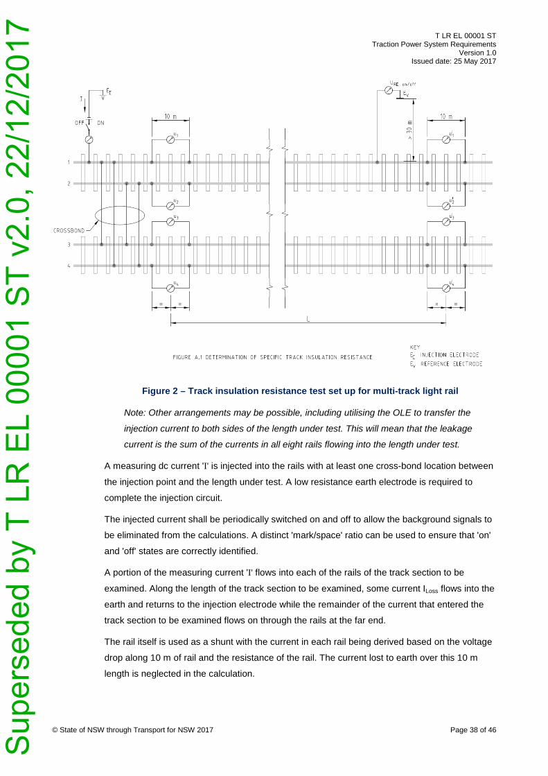
T LR EL 00001 ST Traction Power System Requirements
Version 1.0 Issued date: 25 May 2017
© State of NSW through Transport for NSW 2017 Page 38 of 46
Figure 2 – Track insulation resistance test set up for multi-track light rail
Note: Other arrangements may be possible, including utilising the OLE to transfer the
injection current to both sides of the length under test. This will mean that the leakage
current is the sum of the currents in all eight rails flowing into the length under test.
A measuring dc current 'I' is injected into the rails with at least one cross-bond location between
the injection point and the length under test. A low resistance earth electrode is required to
complete the injection circuit.
The injected current shall be periodically switched on and off to allow the background signals to
be eliminated from the calculations. A distinct 'mark/space' ratio can be used to ensure that 'on'
and 'off' states are correctly identified.
A portion of the measuring current 'I' flows into each of the rails of the track section to be
examined. Along the length of the track section to be examined, some current ILoss flows into the
earth and returns to the injection electrode while the remainder of the current that entered the
track section to be examined flows on through the rails at the far end.
The rail itself is used as a shunt with the current in each rail being derived based on the voltage
drop along 10 m of rail and the resistance of the rail. The current lost to earth over this 10 m
length is neglected in the calculation.
Sup
erse
ded
by T
LR
EL
0000
1 S
T v2
.0, 2
2/12
/201
7

T LR EL 00001 ST Traction Power System Requirements
Version 1.0 Issued date: 25 May 2017
The injection current should be of sufficient magnitude to generate a rail potential significantly
higher than background levels (at least 300% of background).
Greater certainty in the measurement can be achieved by varying the injection current over a
range of values (for example, 20 A, 50 A, 100 A). Inconsistent results should be investigated
rather than simply being averaged into an overall result – at higher voltage levels a lower result
may indicate that very marginal insulation is broken down. Care shall be taken to ensure that
hazardous voltages do not result on the rails or around the reference electrode for the current
injection.
Reversing the injection current and repeating the test will also provide greater certainty in the
measurement by eliminating any polar effects. The results of otherwise equivalent tests of
opposite polarities should be averaged.
A.3. Readiness review A test readiness review should be conducted to ensure that the following conditions exist:
• all normal connections to that rail are in place as required in accordance with Section 7.5
• the rail is clean and dry as permitted in accordance with Section 7.5
• there are no short circuited VLDs or foreign objects which might adversely affect the test.
A.4. Rail resistance The unit resistance of the rail (RRail) shall be verified by measurement using a 4-probe
resistance measurement over the longest practical test length of rail supported on suitable
insulation. If the measured value is significantly different to the value provided by the rail
supplier, the discrepancy shall be investigated and resolved.
A.5. Placement of the voltage reference electrode (half-cell) (Ev) The voltage reference electrode shall be remote from the track, and remote from the reference
electrode for the current injection to get a true reference for the general mass of earth.
Annex A3 of EN 50122-2:2010 indicates >30 m from the section of track under test and >50 m
from the reference for the current injection (EI). The adequacy of the separation in any actual
test set up shall be checked by using a second reference electrode (Ev2) and checking for a
voltage gradient around the proposed voltage electrode (Ev) position.
© State of NSW through Transport for NSW 2017 Page 39 of 46 S
uper
sede
d by
T L
R E
L 00
001
ST
v2.0
, 22/
12/2
017

T LR EL 00001 ST Traction Power System Requirements
Version 1.0 Issued date: 25 May 2017
A.6. Placement of the current injection reference electrode (EI) The reference electrode for the current injection shall be carefully located and configured to
minimise the resulting gradient at the voltage reference location. See Section A.5. The
arrangement for the reference electrode for current injection shall also be such that the resulting
voltage gradient around the length of track under test is minimised. For an accurate
measurement, the current shall flow 'via the general mass of earth' and not via a direct path
between the length of track under test and the current injection electrode. Testing should be
conducted to confirm this.
Ideally, the reference electrode for the current injection should have a lower resistance to earth
than the total track system. Otherwise, the larger portion of the injected voltage will appear
between the injection electrode and the general mass of earth rather than between the rail and
the general mass of earth.
A.7. Measuring equipment The measurement of the current in the rails by the voltage drop technique is something that
involves small differences in large numbers. Accordingly, the following strategies are
recommended:
• use data loggers rather than simple meters
• ensure that the loggers have appropriate anti-aliasing filters to reject 50 Hz mains
frequency effects
• ensure that all the data loggers are time synchronised
• do an initial pre-reading with all the data loggers monitoring the same source
• ensure that the values for all eight rails and the voltage reference correspond to the same
time interval. Sort the steady values corresponding to the 'on' period from those
corresponding to the 'off' period and then do the calculation averaging over a period
sufficient to take account of any variations in the data.
A.8. Calculation RRE = L × N × URE/ILoss
where:
RRE is the specific resistance between track and earth for a single track in Ω·km
L is the length of the section to be measured in kilometres (km)
L should not exceed 2 km (consistent with EN 50122-2:2010 Annex A3)
© State of NSW through Transport for NSW 2017 Page 40 of 46 S
uper
sede
d by
T L
R E
L 00
001
ST
v2.0
, 22/
12/2
017

T LR EL 00001 ST Traction Power System Requirements
Version 1.0 Issued date: 25 May 2017
N is the number of tracks
URE is the voltage between the rail and earth in volts (V) = URE, on - URE, off
ILoss is the sum of the currents entering the section to be measured at the injection end,
less the sum of the currents leaving the section to be measured at the far end, in
amperes (A)
= I1 + I2 + I3 + I4 - I1’ - I2’ - I3’ - I4’
Lm is the measurement length over which the voltage drop in the rail is measured
= 10 m
I1 = L+ × (U+, on – U1, off) / RRail, similarly for I2, I3, I4, I1’, I2’, I3’, and I4’
RRail is the resistance of the rail in Ω/m
A.9. Error study An error study shall be conducted taking account of the absolute and relative errors. The total
error in the determination of RRE shall be less than +/- 10%.
A.10. Safety A safety plan for the test shall be prepared prior to the test and shall be adhered to in the
conduct of the test.
In particular, the safety plan shall address prospective touch potential at all relevant locations
along the rail alignment and also including in the vicinity of the reference electrode for the
current injection (EI). The safety plan shall consider contingencies including the possibilities of a
cable becoming disconnected or an insulator being short-circuited.
The source of injection current shall be current limited to protect against short circuit and shall
have its open circuit voltage limited to a safe level consistent with the safety plan for the test
and risk mitigations in place.
© State of NSW through Transport for NSW 2017 Page 41 of 46 S
uper
sede
d by
T L
R E
L 00
001
ST
v2.0
, 22/
12/2
017

T LR EL 00001 ST Traction Power System Requirements
Version 1.0 Issued date: 25 May 2017
Appendix B Example track insulation resistance test calculation (informative)
These calculations are based on the following values where:
N = 2
L = 2 km
I = 10 A
RRail = 40 × 10-6°Ω/m
Lm = 10 m
Assume that the total length of the system is 10 km, that the injection point is at the mid-point,
and that the track insulation resistance is uniform.
Accordingly,
I1 = I2 = I3 = I4 = I/8 = 1.25 A
This would be measured as
U1 = U2 = U3 = U4 = 500 µV
I1 = I2 = I3 = I4 = 500 × 10-6 / (40 × 10-6 × 10) = 1.25 A
If
U1‘ = U2‘ = U3‘ = U4 = 300 µV
Then
I1‘ = I2‘ = I3‘ = I4‘ = 300 × 10-6 / (40 × 10-6 × 10) = 0.75 A
So
ILoss = 1.25 + 1.25 + 1.25 + 1.25 – 0.75 – 0.75 – 0.75 – 0.75 = 2 A
Then if
URE, on – URE, off = 5 V = URE
And
RRE = 2 × 2 × 5 / 2 = 10 Ω·km
© State of NSW through Transport for NSW 2017 Page 42 of 46 S
uper
sede
d by
T L
R E
L 00
001
ST
v2.0
, 22/
12/2
017

T LR EL 00001 ST Traction Power System Requirements
Version 1.0 Issued date: 25 May 2017
Appendix C Non-cathodically protected structures
The average shifts in the potential of non-cathodically protected buried structures relative to the
Quiescent Potential shall not exceed the limits shown in Table 1 (Excluding IR-drop unless
otherwise noted):
Table 1 – Interference limits for non-catholically protected structures
Asset category Maximum anodic shift
Maximum cathodic shift
Cast iron and carbon steel structures, not embedded in concrete
20 mV [1] -100 mV
Stainless steel structures not embedded in concrete.
20 mV -100 mV
Carbon steel structures, embedded in concrete [4] (Including IR Drop)
200 mV [2] 500 mV [3]
Copper structures, not embedded in concrete. 20 mV -200 mV
Notes:
[1] EN 50162:2004 Table 1.
[2] EN 50162:2004 Section 6.2.
[3] In the case of earth electrodes the possibility of low-conductivity deposits on the
surface of the earth electrode shall be considered.
[4] The risk of corrosion is very dependent on the condition of the concrete covering. If
good covering with high pH then risk is low even with significant anodic potential
shifts. If poor then any anodic shift will increase the risk. See NSW electrolysis
committee's 'Guide for Measurement of Interference Caused by Cathodic Protection
and Railway Drainage Systems' for alternate criteria.
© State of NSW through Transport for NSW 2017 Page 43 of 46 S
uper
sede
d by
T L
R E
L 00
001
ST
v2.0
, 22/
12/2
017

T LR EL 00001 ST Traction Power System Requirements
Version 1.0 Issued date: 25 May 2017
Appendix D Cathodically protected structures D.1. Structure categories
The separation of underground structures into categories is considered necessary to account
for the varying risk profile of certain structures with regards to safety risk and economic value.
Where the consequence of failure is higher more restrictive interference criteria is required than
less risk-prone structures.
CAT 1 is the highest category and these structures include the following:
• high pressure (> 250 kPa) gas and petroleum pipelines
• LPG and propane gas tanks
• ATC coaxial, trunk and junction telecommunication cables
• underground power cables of 11 kV and greater, including associated pilot cables
• pipelines containing toxic materials
CAT 2 structures include the following:
• all steel and other metallic pipelines containing flammable materials not included in CAT 1
• ATC main telecommunication cables
• all steel, cast iron and ductile iron water pipelines equal to or greater than 600 mm
diameter
• underground power distribution cables 240 V and greater but less than 11 kV and
associated pilot cables
• electrical system earthing structures
CAT 3 structures include the following:
• all metallic water pipelines not already included in CAT 2
• ATC subscriber's telecommunication cables
• all other LV (< 415 V) cables which do not form part of the main distribution system, for
example, street lighting and other individual service cables
The average shifts in the potential of non-cathodically protected buried structures relative to the
acceptable protection potential shall not exceed the following limits (excluding IR-drop):
© State of NSW through Transport for NSW 2017 Page 44 of 46 S
uper
sede
d by
T L
R E
L 00
001
ST
v2.0
, 22/
12/2
017

T LR EL 00001 ST Traction Power System Requirements
Version 1.0 Issued date: 25 May 2017
Table 2 – Interference and protection criteria for cathodically protected structures – CAT 1
Structure type
Theoretical level of protection (mV)
Acceptable level of protection (mV) - Stray current present
Acceptable level of protection (mV) - Free from stray current
Actual measured potential to earth (mV)**
Criteria for interference Max. anodic shift (mV)
Criteria for interference Max. cathodic shift (mV)
Steel* -850 -1100 -1000 more anodic than acceptable 10 100
Steel* -850 -1100 -1000 acceptable to -2500 20 100
Steel* -850 -1100 -1000 more cathodic than -2500 20 10
Lead -650 -850 -800 more anodic than acceptable 10 150
Lead -650 -850 -800 acceptable to -1400 20 100
Lead -650 -850 -800 more cathodic than -1400 30 20
Table 3 – Interference and protection criteria for cathodically protected structures – CAT 2
Structure type
Theoretical level of protection (mV)
acceptable level of protection (mV) - Stray current present
acceptable level of protection (mV) - Free from stray current
Actual measured potential to earth (mV)**
Criteria for interference Max. anodic shift (mV)
Criteria for interference Max. cathodic shift (mV)
Steel*, ductile and cast iron
-850 -1100 -1000 more anodic than acceptable 20 100
Steel*, ductile and cast iron
-850 -1100 -1000 acceptable to -2500 20 100
Steel*, ductile and cast iron
-850 -1100 -1000 more cathodic than -2500 30 50
Lead -650 -850 -800 more anodic than acceptable 20 150
© State of NSW through Transport for NSW 2017 Page 45 of 46
Sup
erse
ded
by T
LR
EL
0000
1 S
T v2
.0, 2
2/12
/201
7

T LR EL 00001 ST Traction Power System Requirements
Version 1.0 Issued date: 25 May 2017
Structure type
Theoretical level of protection (mV)
acceptable level of protection (mV) - Stray current present
acceptable level of protection (mV) - Free from stray current
Actual measured potential to earth (mV)**
Criteria for interference Max. anodic shift (mV)
Criteria for interference Max. cathodic shift (mV)
Lead -650 -850 -800 acceptable to -1400 30 100
Lead -650 -850 -800 more cathodic than -1400 40 50
Table 4 – Interference and protection criteria for cathodically protected structures – CAT 3
Structure type
Theoretical level of protection (mV)
acceptable level of protection (mV) - Stray current present
acceptable level of protection (mV) - Free from stray current
Actual measured potential to earth (mV)**
Criteria for interference Max. anodic shift (mV)
Criteria for interference Max. cathodic shift (mV)
Steel* -850 -1100 -1000 more anodic than acceptable 20 100
Steel* -850 -1100 -1000 acceptable to -2500 40 100
Steel* -850 -1100 -1000 more cathodic than -2500 60 50
Lead -650 -850 -800 more anodic than acceptable 20 200
Lead -650 -850 -800 acceptable to -1400 40 100
Lead -650 -850 -800 more cathodic than -1400 60 50
Copper -650 -850 -700 more anodic than acceptable 20 200
Copper -650 -850 -700 acceptable to -1000 40 100
Copper -650 -850 -700 more cathodic than -1000 60 50
Notes:
* Refer to Table 1 in EN 12954: 2001 for details of protection potential criteria, critical potentials and free potentials of steel for varying austenitic or ferritic
alloys, ambient and electrolytic conditions.
** Earth is a reference to copper/copper sulfate half cell
© State of NSW through Transport for NSW 2017 Page 46 of 46
Sup
erse
ded
by T
LR
EL
0000
1 S
T v2
.0, 2
2/12
/201
7