traction systems, general power supply …
TRANSCRIPT

GOVERNMENT OF INDIA
MINISTRY OF URBAN DEVELOPMENT
REPORT OF THE SUB-COMMITTEE ON
TRACTION SYSTEMS, GENERAL POWER SUPPLY ARRANGEMENTS AND ENERGY EFFICIENT SYSTEMS
FOR METRO RAILWAYS
NOVEMBER 2013


Sub-Committee on Traction System, Power Supply & Energy Efficiency Ministry of Urban Development
Final Report
October 2013 Page 2 of 89
Preface 1. Urban centres have been the dynamos of growth in India. This has placed severe stress
on the cities and concomitant pressure on its transit systems. A meaningful and sustainable mass transit system is vital sinew of urbanisation. With success of Delhi’s Metro System, government is encouraging cities with population more than 2 milion to have Metro systems. Bangalore, Chennai, Kolkata, Hyderabad are being joined by smaller cities like Jaipur, Kochi and Gurgaon. It is expected that by end of the Twelfth Five Year Plan India will have more than 400 km of operational metro rail (up from present 223 km).
The National Manufacturing Competitiveness Council (NMCC) has been set up by the Government to provide a continuing forum for policy dialogue to energise and sustain the growth of manufacturing industries in India. A meeting was organized by NMCC on May 03, 2012 and one of the agenda items in that meeting was “Promotion of Manufacturing for Metro System in India as well as formation of Standards for the same”. In view of the NMCC meeting and heavy investments planned in metro systems, thereafter, Ministry of Urban Development (MOUD) have taken the initiative to form a committee for “Standardization and Indigenization of Metro Rail Systems” in May 2012.
The Committee had a series of meetings in June-August 2012 and prepared a Base Paper. With a view to promote domestic manufacturing for Metro System and formation of standards for such systems in India, as suggested in the base paper Ministry of Urban Development has constituted further Sub-Committees which are under:
- Traction system - Rolling stock - Signalling system - Fare Collection System - Operation & Maintenance - Track structure - Simulation Tools
2. The Sub-Committee on Traction Systems, General Power Supply Arrangement and
Energy Efficient Systems for Metros was constituted vide MOUD’s orders dated MOUD F.No.K-14011/26/2012-MRTS/Coord. dated 25th July 2012 and F.No.K-14011/26/2012-MRTS/Coord. Dated 16th Aug 2012, and has the following members: Shri Satish Kumar Director/Elec/DMRC Convener Shri R.N.Lal Advisor/DMRC (Co-opted) Shri Sumit Chatterjee Advisor to OSD (UT)/MOUD Shri Sujeet Mishra Director/TI/RDSO Shri S.Ramasubbu CGM/Elec/CMRL Shri B.G.Mallya CEE/Traction/BMRCL Shri Anil Jangid Consultant, IUT Shri Mangal Dev Director/Alstom Projects India Ltd. Shri Anupam Arora Chief Manager Marketing / Smartgrid-Rail electrification
/ Siemens Ltd. Ms Reeti Sujith Executive Officer/CII Shri Samir Narula General Manager/Medha Servo Drives Pvt. Ltd Shri S.V.R.Srinivas Additional Municipal Commissioner / MMRDA Dr.Rajiv Kumar Secretary General, FICCI Shri D.S.Rawat Secretary General/ASSOCHAM

Sub-Committee on Traction System, Power Supply & Energy Efficiency Ministry of Urban Development
Final Report
October 2013 Page 3 of 89
3. The detailed terms of reference of the sub-committee is given in Annexure I terms of reference of the Sub-Committee on Traction Systems, General Power Supply Arrangement and Energy Efficient Systems broadly included the following: (i) Traction Systems 750V/1500V dc third rail or 25kV ac OCS
(ii) General Power Supply: Internal Power Supply Distribution System
(iii) Energy Efficient Systems
4. The Sub-Committee had 06 meetings spread over ten days and has since completed the
assigned task, which effort has culminated into this Report. Major contents of the Report are chapters on traction system, power distribution system, energy efficiency measures and scope of further studies. The key findings of the investigation are given in Executive Summary. After the report was submitted in March 2013, observations of three officers were received from MoUD in July/August 2013. On consideration of their observations/input, certain paragraphs viz., 0.1.3, 0.1.4, 0.6, 1.2, 2.6.2, 2.6.5, 2.6.5.4 ofthe earlier report have been amplified and some factual information has been added in these paragraphs. However, these do not change the main recommendations.
(SATISH KUMAR) Director (Elect.),DMRC (upto 31.03.2013)
Presently Principal Adviser (Electrical), DMRC Convener Sub Committee on
Traction System, GPSA & EES For Metro Railways
Sub-Committee on Traction System, Power Supply & Energy Efficiency Ministry of Urban Development
Final Report
October 2013 Page 4 of 89
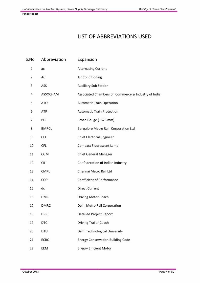
! ! LIST!OF!ABBREVIATIONS!USED!
! ! !
S.No! Abbreviation! Expansion!!
1! ac! Alternating!Current!
2! AC! Air!Conditioning!
3! ASS! Auxiliary!Sub!Station!
4! ASSOCHAM! Associated!Chambers!of!!Commerce!&!Industry!of!India!
5! ATO! Automatic!Train!Operation!
6! ATP! Automatic!Train!Protection!
7! BG! Broad!Gauge!(1676!mm)!
8! BMRCL! Bangalore!Metro!Rail!!Corporation!Ltd!
9! CEE! Chief!Electrical!Engineer!
10! CFL! Compact!Fluorescent!Lamp!!
11! CGM! Chief!General!Manager!
12! CII! Confederation!of!Indian!Industry!
13! CMRL! Chennai!Metro!Rail!Ltd!
14! COP! Coefficient!of!Performance!
15! dc! Direct!Current!
16! DMC! Driving!Motor!Coach!
17! DMRC! Delhi!Metro!Rail!Corporation!
18! DPR! Detailed!Project!Report!
19! DTC! Driving!Trailer!Coach!
20! DTU! Delhi!Technological!University!
21! ECBC! Energy!Conservation!Building!Code!
22! EEM! Energy!Efficient!Motor!

Sub-Committee on Traction System, Power Supply & Energy Efficiency Ministry of Urban Development
Final Report
October 2013 Page 5 of 89
23! EMC! Electro!Magnetic!Compatibility!
24! EMI! Electro!Magnetic!Interference!
25! FICCI!!Federation!of!Indian!Chambers!of!Commerce!&!Industry!
26! GIS! Gas!Insulated!Switchgear/Substation!
27! GTKM! Gross!Ton!Kilometers!
28! HSCB! High!Speed!Circuit!Breaker!
29! HT! High!Tension!
30! IIT! Indian!Institute!of!Technology!
31! IPR! Intellectual!Property!Rights!!
32! IR! Indian!Railways!
33! IUT! Institute!of!Urban!Transport!
34! KMRCL! Kolkata!!Metro!Rail!Corporation!Ltd!
35! kV! Kilo!Volts!
36! kVA! Kilo!Volt!Amperes!
37! kWh! Kilo!Watt!Hour!
38! LCD! Liquid!Crystal!Display!
39! LED! Light!Emitting!Diode!
40! LEED! Leadership!in!Energy!&!Environmental!Design!
41! LRT! Light!Rail!Transit!
42! LT! Low!Tension!
43! MC! Motor!Coach!
44! MMRDA! Mumbai!Metropolitan!Region!Development!Authority!
45! MOUD! Ministry!of!Urban!Development!!
46! MRTS! Mass!Rapid!Transit!System!
47! NMCC! National!Manufacturing!Competitiveness!Council!
48! O&M! Operation!&!Maintenance!

Sub-Committee on Traction System, Power Supply & Energy Efficiency Ministry of Urban Development
Final Report
October 2013 Page 6 of 89
49! OCS! Overhead!Catenary!System!
50! OHE! Over!Head!Equipment!!
51! PCC! Point!of!Common!Coupling!
52! PHPDT! Peak!Hour!Peak!Direction!Traffic!
53! PSD! Platform!Screen!Door!
54! PV! Photo!Voltaic!
55! PVC! Price!Variation!Clause!
56! RATP!Régie!Autonome!des!Transports!Parisiens!(French:!Paris!Transport!Authority)!
57! RDSO! Research!Design!and!Standards!Organisation!
58! RER!Réseau!Express!Régional!(French!for!Regional!Express!Network)!
59! RITES! Rail!India!Technical!and!Economic!Service!
60! RSS! Receiving!Sub!Station!
61! RSSB! Rail!Safety!and!Standards!Board!
62! SCMS! Stray!Current!Monitoring!System!
63! SEC! Specific!Energy!Consumption!
64! SG! Standard!Gauge!(1435!mm)!
65! TC! Trailer!Coach!
66! TI! Traction!Installation!
67! TR! Ton!of!Refrigeration!
68! TSS! Traction!Sub!Station!
69! U/G! Underground!
70! UIC!Union!Internationale!des!Chemins!de!fer!(International!Union!of!Railways)!
71! UPS! Uninterruptible!Power!Supply!
72! VAC! Ventilation!and!Air!Conditioning!
73! VAV! Variable!Air!Volume!!

Sub-Committee on Traction System, Power Supply & Energy Efficiency Ministry of Urban Development
Final Report
October 2013 Page 7 of 89
74! VOC! Volatile!Organic!Compound!
75! VRV! Variable!Refrigerant!Volume!
76! VVVF! Variable!Voltage!Variable!Frequency!

Sub-Committee on Traction System, Power Supply & Energy Efficiency Ministry of Urban Development
Final Report
October 2013 Page 8 of 89
CONTENTS 0.0 EXECUTIVE SUMMARY..............................................................................................10
0.1 Traction System ......................................................................................................................10
0.2 Auxiliary & Traction Power Supply ..........................................................................................14
0.3 Indigenization – Status, Constraints and way forward ............................................................15
0.4 Energy Efficiency.....................................................................................................................16
0.5 Scope of further studies ..........................................................................................................18
1.0 INTRODUCTION ..........................................................................................................20
1.1 Background .............................................................................................................................20
1.2 Meetings of the Committee .....................................................................................................21
1.3 Terms of Reference.................................................................................................................22
2.0 TRACTION SYSTEM ...................................................................................................24
2.1 Objectives of traction system ..................................................................................................24
2.2 Study of traction systems adopted by various metros world over ...........................................24
2.3 Study of Current / Future Trends (Metros built in last 5 years) ...............................................31
2.4 Merits and Demerits of various traction systems.....................................................................33
2.5 Technical feasibility of different traction systems and their relationship with peak hour peak direction traffic (PHPDT)...................................................................................................................38
2.6 Economic Viability and Sustainability: Analysis of capital cost of various traction systems for different levels of traffic.....................................................................................................................38
2.7 Reliability and redundancy measures .....................................................................................51
2.8 Maintenance needs and philosophy of maintenance of traction system.................................53
2.9 Economic Viability for a sample corridor of 25 km length on via duct .....................................53
2.10 Upcoming technologies .........................................................................................................57
2.11 Conclusion and the way forward ...........................................................................................58
3.0 INTERNAL POWER DISTRIBUTION SYSTEM ..........................................................62
3.1 Internal Distribution System ....................................................................................................62
3.2 Technical Feasibility ................................................................................................................62
3.3 Pros and cons of different distribution networks......................................................................64
3.4 Cost Economics ......................................................................................................................65
3.5 Recommendations ..................................................................................................................66
4.0 Indigenization .............................................................................................................72
4.1 Currently Imported Items.........................................................................................................72
4.2 Indigenization Approach..........................................................................................................72
4.3 Constraints in indigenization ...................................................................................................72
4.4 Strategy of indigenization ........................................................................................................73

Sub-Committee on Traction System, Power Supply & Energy Efficiency Ministry of Urban Development
Final Report
October 2013 Page 9 of 89
5.0 ENERGY EFFICIENCY ................................................................................................75
5.1 Energy Saving Measures in Traction [20-23] ..........................................................................76
5.2 Auxiliary system energy efficiency ..........................................................................................76
5.3 Latest Trends ..........................................................................................................................77
5.4 Certain advances in energy saving technologies ....................................................................80
5.5 Study of existing policy/guidelines regarding use of energy efficient systems........................82
5.6 Renewable / Non-polluting Energy System.............................................................................83
5.7 Energy Efficiency Measures in Metros as per NOVA/ COMET study .....................................85
6.0 SCOPE OF FURTHER STUDIES ................................................................................87
Bibliography.........................................................................................................................87
Annexure ..............................................................................................................................89

Sub-Committee on Traction System, Power Supply & Energy Efficiency Ministry of Urban Development
Final Report
October 2013 Page 10 of 89
0.0 EXECUTIVE SUMMARY
0.1 Traction System
0.1.1 Summary
Based on detailed study of various traction systems adopted world over, the study on technical feasibility of traction systems for various levels of traffic and technological development, following position emerges as given in Table-1 below:
Table-1
Type of MRTS
PHPDT Traction Voltage Feasible
Cap Cost*
Energy re-generation
Remark
750 V dc third rail
(a) 125% (a) 18-20%
1500 V dc OCS
(b) 115% (b) 20-22%
LRT 15000 to 30000
25 kV ac OCS
(c) 100 (c) >35%
(a) 750 V dc third rail
(a) 135% (a) 18-20%
(b) 1500 V dc OCS
(b) 115%
(b) 20-22%
Medium 30000 to 45000
(c) 25 kV ac OCS (c) 100 (c) >35%
(a) 1500 V dc (a) 120% (a) 20-22% (b) 25 kV ac (b) 100 (b) >35%
(a) 750 V dc third rail does not have overhead conductor system. It looks good from aesthetic point of view on elevated section. (b) & (c) In U/G OCS does not affect aesthetics
Heavy MRTS
> 45000 <75000
2X25kV ac May be adopted in busy congested area of city where there are limitations of getting supply at 66kV/22kV and has lesser EMC/EMI problems
*The capital cost pertains to electrification system cost only and it does not capture the impact on rolling stock and civil infrastructure costs due to traction system Note: 1. PHPDT on 750 V dc is validated by subgroup on theoretical study (Annex V). 2. Issue of aesthetics, however, is a tenuous one in decision-making matrix.
While taking decision based on aesthetics, it should be considered that there is widespread acceptance of OCS even in tourism centric countries like Switzerland and industrialized nations like Japan.
0.1.2 Energy scenario in different traction system
0.1.2.1 Actual records of DMRC (BG Lines - 120 km) & BMRCL (7 Km) reveal an energy
saving of 25% in 25 kV ac traction system operating with acceleration of 0.82 m/s2 and maximum speed of 75 kmph versus 750 V dc traction system in BMRCL operating at acceleration of 1.0 m/s2 and but lower maximum speed of 65 kmph.

Sub-Committee on Traction System, Power Supply & Energy Efficiency Ministry of Urban Development
Final Report
October 2013 Page 11 of 89
0.1.2.2 Studies indicate that the energy saving in 25 kV ac system may increase to above 35% with the use of higher acceleration of 1.0 m/s2, using 4M+2T rake as compared to existing 750 V dc 4M+2T i.e. both operating with same acceleration and speed.
0.1.2.3 With the increasing cost of electric energy & in an effort to optimize traction
energy, now metros working on 750V dc / 1500V dc are exploring methods to improve recuperation of regenerated energy upto 32% even with additional expenditure by using additional technology like inverter, storage devices at sub-stations which are under development and trial in different countries. Cost of these additional technologies, which is substantial at present, however is expected to reduce with the passage of time, deployment of modern electronics & software.
0.1.3 Impact on Tunnel Diameter
0.1.3.1 It is reported that nowadays, almost similar Machinery & Plant and other facilities
are required for tunnelling of diameter ranging from 5.2 to 5.8 m and therefore only very marginal increase in the cost is expected due to increase in size of the tunnel as discussed in para 2.6.5.
0.1.3.2 Studies indicate that increase in cost due to higher tunnel diameter of 5.6 m in
case of 25 kV is substantially offset by reduction in cost due to lesser number of substation and other associated benefits of larger tunnel diameter. Actual differential in cost will depend upon the soil conditions, land availability in the city and the following: • Dimensions (length, width and height) of the coach • Number coaches in train and length of train • Minimum curvature • Type of evacuation (side or front) • Traction Voltage • OCS or Third Rail • Soil Temperature • Ideally an optimum size can be arrived at by considering the above factors.
However, for practical purposes, for Indian conditions, a tunnel diameter for new Metros may be from 5.2 to 5.7 m
0.1.3.3 Other things being same (coach dimensions, evaluation strategy etc.),
theoretically, the adoption of dc third rail traction system (750V or 1500V dc) will require smaller diameter tunnel. However, tunnel diameters adopted in India don’t establish a causal relationship between the traction voltage and tunnel diameters. Experience of many world Metros working with 750 V dc third rail traction system indicate that they have adopted tunnel diameter of around 5.6 m, to derive other benefits of larger tunnel diameter as increase in cost is marginal due to increased earth work and jacketing with the use of modern tunnel boring machines (eg. 5.4 m for dc & 5.55/5.6 m for 25 kV ac). As per experts, tunneling cost as a thumb rule can be taken as proportional to tunnel diameter i.e. variation of about 3 to 4% between 5.4 & 5.6 m.
0.1.4 Cost of rolling stock
0.1.4.1 The cost data of rolling stock as per actual contract awarded by various metros in
the country are as under:

Sub-Committee on Traction System, Power Supply & Energy Efficiency Ministry of Urban Development
Final Report
October 2013 Page 12 of 89
Table 2 Current cost of metro coaches of different Indian Metros
SN Type of traction
Name of Metro
Estimated cost per coach (Rs. In cr) with taxes & including export benefits as on 31st Dec 2012
Estimated cost per coach with spares without taxes and without export benefits as on 31st December 2012
Remarks
BMRCL**
9.99 9.41 2.88m. wide, 1.0m/s2, 67% motored axle, certain better features compared to KMRCL
1 750V dc
KMRCL
9.29 8.05 2.88m. wide, 1.0m/s2, 67% motored axle, flexible PVC clauses for 66% component without any clamping.
CMRL 8.74 8.28 2.9m wide, 0.82m/s2, 50% motored axle, flexible PVC clauses for 66% component without any clamping.
DMRC** RS2 9.26 8.73 3.2m wide, 0.82m/s2,
50% motored axle RS3 10.09 9.97 2.9m wide, 0.82m/s2,
50% motored axle Phase III (RS10)
8.58 (1st Apr 2013
7.91 3.2m wide, 1.0m/s2, 67% motored axle, more energy efficient
2 25kV ac
Hyderabad** (HMRL)
10.23* 8.77 2.9m. wide, 1.0m/s2, 67% motored axle,
*Unlike other Metros, this figure is firm price with no variation due to exchnage rate throughout the contract period and also without any deemed benefit. **PVC clauses in respect of DMRC, BMRCL and HMRL have lower flexible component with a fixed clamping of 3%, unlike, KMRCL and CMRL.
0.1.4.2 The propulsion equipment of the ac rolling stock comprises of two additional major
equipment, viz. transformer and front end converter. Examination of quotes received by DMRC in 2000, for AC and DC rolling stock of same performance requirement in the RS-1 tender for underground line shows that the cost of 25 kV ac rolling stock is more than 1500 V dc rolling stock by Rs 37 lakhs, i.e. by 9%. Total additional cost of rolling stock of 25 kVac for 68 coaches for this line worked out to Rs.25 crores and reduction in traction & power supply arrangement from 1500 V dc to 25 kV ac for the same line was Rs.64 crores. However,

Sub-Committee on Traction System, Power Supply & Energy Efficiency Ministry of Urban Development
Final Report
October 2013 Page 13 of 89
advancements in technology like use of higher dc link voltage and single transformer for multiple motor coaches are now resulting in reduction in cost of ac rolling stock. The difference in 25 kV ac vis-à-vis 750 V dc rolling stock would be lower than 9%.
0.1.4.3 Incidentally, the procurement experience of different Indian Metros shows that the
cost of 25kV ac rolling stock is now comparable with 750V dc rolling stock. Though the above figures indicate the cost of 25 kV ac rolling stock is comparable with the 750 V dc rolling stock but this gets influenced by many factors such as: (a) Number of coaches (b) The specifications viz. acceleration, deceleration, scheduled speed, special
features required which are entirely not the same in above cases. (c) DC link voltage (d) Commercial Conditions: defect liability period, indigenization clauses, price
variation, delivery period, time frame for completion, ambient conditions, etc. (e) Risk factors perceived by the bidders
0.1.4.4 It is worth mentioning that the propulsion equipment forms nearly 20-25% of the cost of rolling stock and this gets influenced in 3-phase drive systems by the additional equipment required in 25 kV ac (traction transformer and converter) and in dc the size of the traction equipment because of lower permissible dc link voltage as compared to higher permissible dc link voltage in ac stock as explained in Para 2.6.2.8.
0.1.5 World Scenario and Other Recent Developments
0.1.5.1 Out of 184 transit systems worldwide having 573 lines and 9394 stations with a
combined length of 10641 km, more than 50% have 750V dc third rail system. Over 12 heavy metros have overhead 1500 V dc system. Recently heavy metros like Seoul, Delhi, Hyderabad and Chennai have adopted 25kV ac system. Bangalore Metro with projected traffic level upto 45,000 PHPDT has adopted 750V dc system.
0.1.5.2 1500V dc third rail has recently been adopted by Guangzhou and Shenzhen
Metros in China on a few lines. It is learnt that this has been developed by Chinese Industry recently in association with European industry. The Committee visited Guangzhou Metro to study experience and design aspect of 1500V dc third rail system. Summary of visit is given in Para 2.2.3.2.
0.1.5.3 Regeneration of energy has been feasible in modern rolling stock because of
development of VVVF drive in 1990s & old metro Rolling Stock does not have this feature.
0.1.5.4 Studies indicate that 1500 V dc or 25kV ac is essentially required for PHPDT
above 45000. Based on the cost incurred by Indian Metros in recent past it is noted that 25 kV ac is economical, from direct cost of electrification point of view, compared to 750V dc even above a PHPDT of 30,000 both from initial cost point of view as well as energy efficiency.
0.1.5.5 From aesthetic point of view, 750 V/1500 V dc third rail gives better aesthetics as it
does not have overhead conductor system (OCS).
0.1.5.6 2x25kV ac system, which is energy efficient and have lesser EMC/EMI problems, can offer viable solution for congested city. This traction system has been adopted

Sub-Committee on Traction System, Power Supply & Energy Efficiency Ministry of Urban Development
Final Report
October 2013 Page 14 of 89
by Seoul Metro on their Sin Bundang line. It requires further detailed study for adopting in Indian Metros.
0.1.6 Indigenisation Level of Hardware and Software of Traction System
0.1.6.1 For modern 750V dc traction system some of the major systems like low loss
composite aluminium third rail, oil-less (dry type) transformer rectifier set, dc switchgear, high speed circuit breaker, bus duct etc. are not available indigenously.
0.1.6.2 Modern 25kV ac system, adopted by Delhi Metro, has a few fittings different than
and superior to Indian Railways. Some of the sub-systems like light weight section insulators, typical potential transformer and current transformer, neutral section arrangement, 25 kV gas insulated switchgear in traction sub stations and switching stations, rigid overhead system, synthetic insulators etc. are imported.
0.1.6.3 Items for indigenisation of 750 V dc and 25 kV ac on immediate basis has been given in para 4.4.5 and also in annexure XII.
0.1.6.4 Simulation programmes are essential to determine and predict requirement of
traction load, for various headways of trains, study of EMC/ EMI effect, sizing of equipment etc. Presently, these are propriety of few firms in the world and metros are getting it done from them. But neither metros have any knowledge about these simulation programme nor it is available with them. There is need for development of simulation package in India with the help of institutes like DTU, IITs and industry.
0.1.7 The Way Forward
0.1.7.1 In view of the above, presently Metros in India may consider adoption of 25 kV ac
or 750 V dc. The objective and considerations for selection of 750 V dc or 25 kV ac should keep in view route of a particular rapid transit line in the city, elevated or underground, above knowledge of technical feasible systems, their capabilities, economic viability based on capital cost and operational cost, platform screen doors, aesthetics and environmental conditions peculiar to the area of the city.
0.1.7.2 1500V dc third rail may also be considered by some metro on experimental basis
for few lines involving higher PHPDT on aesthetic consideration, which can be examined later on for further consideration.
0.2 Auxiliary & Traction Power Supply
0.2.1 Study reveals that it is essential to have ring main or duplicate system at high
voltage from reliability and continuous availability of power supply point of view. Most of the metros world over have adopted ring main system at high voltage of 33 kV/22 kV or 11 kV depending upon local power supply network in use. This starts from receiving sub-station. At each station, auxiliary sub-station steps down to 400/ 230 V from 33 kV or 22 kV or 11 kV for further distribution.
All the metros in India have adopted either ring main or duplicate system. Mostly, 33kV ring main has been adopted in India by Delhi, Chennai, Hyderabad and Bangalore. Metro lines in Mumbai have adopted 22kV and in Kolkata 11kV as prevalent there.

Sub-Committee on Traction System, Power Supply & Energy Efficiency Ministry of Urban Development
Final Report
October 2013 Page 15 of 89
0.2.2 To meet emergent situation in case of failure of 33kV, the stations are provided with DG sets for essential services to meet essential loads like signaling, fire protection, lighting etc.
0.2.3 In U/G stations major equipment design has to give due attention to eliminate fire
hazards. Special panels, fire retardant cables, fire retardant dry type transformers have been used. Some of these equipment like fire detection cable, fire alarm panel etc. are still not available indigenously. A few equipment have been developed and are being manufactured in India.
0.2.4 In case of 750/1500 V dc system some of the Metros have adopted common ring
main 33 kV cable system for traction and auxiliary supplies depending upon the reliability of grid supply voltage (Dubai, Guangzhou, Kolkata) instead of separate ring main system for traction and auxiliary supply (Bangalore). Techno-economic study may be taken up while planning for a new Metro system, peculiar to the city.
0.3 Indigenization – Status, Constraints and way forward
0.3.1 Current Status
0.3.1.1 750V dc system: Modern technology 750V traction system of Bangalore Metro
uses composite aluminium third rail, dry type of transformer rectifier, dc switch gear and high speed breaker (HSCB), bus duct. These are all presently imported and have a small volume of requirement. Other components like cable, RSS equipment are indigenously available. Indigenization of these imported components need to be explored through industry dealing with Railway traction equipment.
0.3.1.2 25kV ac system: Delhi Metro while adopting 25kV ac system have imported few
components / equipment like light weight section insulator, potential transformer, neutral section, rigid OCS and GIS from reliability and maintainability point of view. Delhi Metro has placed developmental order for section insulator and indigenization of other items needs to be explored.
Copper Conductor, mast and other switch gear are now available indigenously. Synthetic insulator has been developed indigenously & used extensively on Delhi Metro.
0.3.2 Constraints in Indigenization
0.3.2.1 Local industries do not have know-how for the design, control, manufacture and
quality assurance of imported items.
0.3.2.2 Volumes may not be attractive for local industries, interaction with global players to set up a manufacturing base in India in some cases needs to be pursued.
0.3.2.3 There would be an issue of IPR with the OEM which requires to be discussed and
examined further.
0.3.3 Strategy of Indigenization
0.3.3.1 Common enabling specifications of systems/sub-systems for all metros can increase volume of requirement and encourage Indian industries having facilities for manufacturing similar items for Indian Railways for indigenization of these items.

Sub-Committee on Traction System, Power Supply & Energy Efficiency Ministry of Urban Development
Final Report
October 2013 Page 16 of 89
0.3.3.2 Some items can be entrusted for indigenization through industries by overseas
firms/ units.
0.3.3.3 However, to ensure technology up-gradation, investments by Indian industries, it is necessary to have a policy framework for encouraging indigenization and to detail out mechanism for assured market.
0.3.4 Development of Software and Hardware
0.3.4.1 There is need for tie up with Engineering Colleges/ DTU/ IITs for development of
software, simulation packages/innovation. Development of sub-systems, and hardware for availability and maintenance needs and substitution for obsolescence etc.
0.3.4.2 RDSO while doing akin work for Indian Railways may also be encouraged to take
up similar work in association with experts/Indian Institutions.
0.4 Energy Efficiency
0.4.1 Regeneration absorption capability
0.4.1.1 While on 25kV ac, re-generation above 30% is possible to be achieved due to higher voltage, longer feeding zone but on 750V dc system, it remains around 18 to 20% only because of voltage drop. Measures are under development in other countries to further retrieve re-generated energy in 750V dc system. In this regard following energy storage equipment at substation are reported to be under use/trial in other countries:
• Fly wheel • Super capacitor • High capacity battery • Inverter
0.4.1.2 These need to be studied further & discussed with developers.
0.4.2 Energy Efficiency Measures in Metros
0.4.2.1 A study conducted on energy efficiency has identified following factors in design of
Metro systems as given in Table 3 below. Status in respect of these factors in DMRC, BMRCL and CMRL is given in juxtaposition in Table 3.

Sub-Committee on Traction System, Power Supply & Energy Efficiency Ministry of Urban Development
Final Report
October 2013 Page 17 of 89
Table 3
Improving Energy Efficiency Contribution towards Energy Efficiency SN Factor DMRC BMRCL CMRL
1 Gradient Adverse Adverse Adverse 2 Station Spacing Neutral Neutral Neutral 3 Air-conditioning (Normally
takes upto 20% of the energy)
Adverse - -
3 Regenerative Braking (Max 50%)
Favourable Favourable Favourable
4 Driving skills (ATO, ATP) Favourable Favourable - 5 Light Weight Stock Favourable Favourable Favourable 6 3-Phase technology Favourable Favourable Favourable 7 25kV traction Favourable - Favourable
0.4.2.2 A study conducted by NOVA/COMET lists out following Energy Efficiency
Measures of stations, infrastructure and rolling stock requiring due attention at the time of design stage/during operation. List of items, their status of adoption in DMRC BMRCL, CMRL is given below:
Table 4
SN Description DMRC BMRCL CMRL A Infrastructure 1 Intelligent ventilation to reduce AC
requirement Yes -- Yes
2 Adopt higher traction voltage Yes -- Yes 3 Use low loss Al conductor third rail NA Yes NA 4 Use of line side capacitors NA Not Used NA 5 Track profile and curvature OK Adverse OK 6 Underground or elevated (as
underground section consumes more energy
Mix Mix Mix
B Stations 7 Escalator sensors and speed Yes Yes -- 8 Modern auxiliary equipment e.g.
AFC Yes Yes Yes
9 LED lighting Partly Partly -- 10 Platform screen doors (PSD) Phase-III -- Yes 11 Adjust air conditioning Yes -- -- C Rolling Stock 12 Utilization of regenerated energy
during off peak hours Yes -- --
13 Use of energy storage device or substation inverter in dc system
NA Not Used --
14 Adjust saloon temperature according to passenger load
Yes Yes --
15 Light weight rolling stock Yes Yes Yes

Sub-Committee on Traction System, Power Supply & Energy Efficiency Ministry of Urban Development
Final Report
October 2013 Page 18 of 89
SN Description DMRC BMRCL CMRL 16 Through gangways Yes Yes Yes 17 Driverless train operation Phase-III -- -- 18 On board control Yes Yes -- 19 LED lighting Phase-III -- -- D Operational Strategies 20 Vary fares --To be examined-- -- 21 Minimize delays/manage dwell
times Yes -- --
22 Vary speeds --To be examined-- -- 23 Adopt coasting --To be improved-- -- 24 Off peak service frequency Yes Yes --
0.5 Scope of further studies
0.5.1 Further studies would be desirable on following topics to enhance the benefits of
standardization, indigenization and up gradation / continuous adoption of emerging technologies with a view to remain modern and avail benefits of evolving technologies.Some of the areas identified for immediate studies are: (a) 2x25kV ac traction system for metro (b) Adoption of new technology at substation level to improve level of regeneration
in dc traction system (c) On merits and demerits for adopting two ring main circuits, one for traction and
other for auxiliary with provision to meet emergency requirement by either circuit vis-à-vis three ring main circuits and four ring main circuits in dc traction system.
(d) Merits and demerits of taking auxiliary power supply (33/11 kV) at each metro sub-station directly from Electricity Supply Company rather than running 33 kV cables for transfer of power on via-ducts.
(e) Strategy for cost reduction of 750V/1500V dc traction system by adopting design criteria of outage of one transformer rectifier set instead of one TSS.
(f) Energy efficiency measures similar to European rail road research map for adopting in Indian Metros.
(g) Simulation studies to evaluate energy saving in 25 kV ac vis-a-vis 750 V dc traction system with similar performance and under similar operating & climatic conditions with advance technology 4M+2T rake composition.
(h) Based on experience of Ahmedabad Metro of 1500 V dc third rail system and
further studies, development of Engineering & Designs for this system and its
interface with Rolling Stock/Current Collecting Device (CCD) can be taken
up.
0.6 Examination of comments received from MoUD from June to August 2013.
After the report was submitted in March 2013, comments of three officers were received from MoUD vide their letter no. FNK-14011/26/2012/MRTS/Coord (Pt II) on 11th July, 19th July and 8th August 2013 respectively. These observations have been duly examined by the members of the sub-committee in their meetings held in July & September 2013. On consideration of their observations/input, certain

Sub-Committee on Traction System, Power Supply & Energy Efficiency Ministry of Urban Development
Final Report
October 2013 Page 19 of 89
paragraphs viz., 0.1.3, 0.1.4, 0.6, 1.2, 2.6.2, 2.6.5, 2.6.5.4 of the earlier report have been amplified and some factual information has been added in these paragraphs. However, these do not change the main recommendations.
All the statements made in the report are based on carefully researched factual data and is supported with documentary records.
(SATISH KUMAR) Director (Elect.),DMRC (upto 31.03.2013)
Presently Principal Adviser (Electrical), DMRC Convener Sub Committee on
Traction System, GPSA & EES For Metro Railways

Sub-Committee on Traction System, Power Supply & Energy Efficiency Ministry of Urban Development
Final Report
October 2013 Page 20 of 89
1.0 INTRODUCTION
1.1 Background
1.1.1 With the success of Delhi Metro Rail Corporation in constructing 189 km of Metro
network in Delhi and NCR, the country has been moving on the path of accelerating the development of Metro rail and other Rail based urban transport solutions in cities. Cities of Mumbai, Bangalore, Hyderabad, Chennai and Kolkata along with Delhi (Phase III) are constructing Metro rail. Some smaller cities like Jaipur, Kochi and Gurgaon too are also constructing metros. With the new policy of Central Government to empower cities and towns with more than two million population to plan and construct Metro rail, more cities and towns are going to come on Metro map of India. It is expected that by end of the Twelfth Five Year Plan, India will have more than 400 km of operational metro rail (up from present 223 km).
1.1.2 With a view to promote domestic manufacturing for Metro System and formation of
standards for such systems in India, Ministry of Urban Development has constituted Sub-Committees for different subsystems of metro. The Sub-Committee on Traction System was constituted vide MoUD’s orders dated 25/7/2012 and 16/8/2012 (enclosed as Annexure IA & IB). Names of the members of the Sub-Committee, their designation and number of meetings attended by them are given below:
Name Designation Meetings
Shri Satish Kumar Director/Elec/DMRC Convener
8/8
Shri R.N.Lal Advisor/DMRC (Co-opted)
8/8
Shri Sumit Chatterjee Advisor to OSD (UT)/MOUD
6/8
Shri Sujeet Mishra Director/TI/RDSO
6/8
Shri S.Ramasubbu CGM/Elec/CMRL
8/8
Shri B.G.Mallya CEE/Traction/BMRCL
8/8
Shri Anil Jangid Consultant, IUT
8/8

Sub-Committee on Traction System, Power Supply & Energy Efficiency Ministry of Urban Development
Final Report
October 2013 Page 21 of 89
Shri Mangal Dev Director/Alstom Projects India Ltd.
3/8
Shri Anupam Arora Chief Manager Marketing/ Smart Grid – Rail Electrification / Siemens Ltd
3/8
Ms Reeti Sujith Executive Officer/CII
1/8
Shri Samir Narula General Manager/Medha Servo Drives Pvt. Ltd
1/8
Shri S.V.R.Srinivas
(Shri S.P. Khade, Director(Tech)/MMRDA)
Additional Municipal Commissioner / MMRDA
Nil
(2)
Dr. Rajiv Kumar Secretary General, FICCI
Nil
Shri D.S.Rawat Secretary General/ASSOCHAM
Nil
1.1.3 Though initially Shri Sujeet Mishra, Director, RDSO and Shri Jaideep, Director,
Railway Board were nominated by MoUD as railway nominees but thereafter, Railway Board confirmed the nomination of Shri Sujeet Mishra only, who attended six meetings. From the Industry side, Ms Reethi Sujith from CII, and Shri Samir Narula of M/s Medha have attended only one meeting Shri Mangal Dev of M/s Alstom and Shri Anupam Arora of Siemens have attended three meetings. In place of Shri S.V.R. Srinivas, Additional Municipal Commissioner/MMRDA Shri S.P. Khade, Director (Technical)/MMRDA attended one meeting. Dr. Rajiv Kumar, Secretary General, FICCI and Shri D.S. Rawat, Secretary General/ASSOCHAM did not attend any meeting.
1.2 Meetings of the Committee
1.2.1 The Committee had six meetings on the following dates for discussion and
preparation of the report: (a) Sept 04, 2012 (b) Oct 04, 2012 (c) Dec 05/06, 2012 (d) Dec 27/28, 2012 (e) Feb 12/13, 2013 (f) March 12-15, 2013 (g) Sub-committee members met on 23rd July 2013 to discuss the issues raised by
MD/BMRCL and comments of Shri Sudesh Kumar, formerMember Electrical, Railway Board, as forwarded by MoUD which was participated by S/Sri Satish Kumar, R.N. Lal, S. Ramasubbu, B.G. Mallya, Sujeet Mishra and Anil Jangid.

Sub-Committee on Traction System, Power Supply & Energy Efficiency Ministry of Urban Development
Final Report
October 2013 Page 22 of 89
(h) Sub-committee members viz. S/Sri Satish Kumar, R.N. Lal, S. Ramasubbu, B.G. Mallya, Sujeet Mishra and Anil Jangid again met on 12/13 September 2013, to discuss the comments of Shri R.K. Bhatnagar, Advisor Electrical(G), Railway Board, as forwarded by MoUD. Based on this discussion of 23rdJuly and 12/13 September, and on consideration of their observations/ input, certain paragraphs viz. 0.1.3, 0.1.4, 0.6, 1.2, 2.6.2, 2.6.5, 2.6.5.4 of the report have been amplified and some factual information has been added in these paragraphs.
1.3 Terms of Reference
The terms of reference of the sub-committee are as under:
1.3.1 Traction Systems 750V/1500V dc third rail or 25kV ac OCS
(i) Study of traction systems adopted by various metros around the world
including year of commissioning of these metros. (ii) Study current trends i.e. traction system being adopted by newly built metros
(say, last five years) and metros being built (iii) Establishing a relation between type of traction system and max PHPDT that
can be catered to by 750 V dc/1500 V dc third rail and 25 kV ac OCS (iv) Analysis of capital cost of various types of traction systems for different levels
of traffic – for a sample corridor. Such analysis shall include:
a. Direct cost of traction power system b. Direct cost of rolling stock c. Weight reduction of rolling stock (and consequent energy savings) and
impact on operating cost d. Cost impact of regenerative braking (e.g. DC system may require
additional investment in inverters for utilising the regenerated energy) e. Civil infrastructure cost (e.g. Cost impact of increased tunnel diameter)
(v) Study of capital cost of electrification of DMRC, BMRCL, CMRL, KMRC, Indian
Railways, Kolkata Metro etc. and compare operating costs on both types of tractions
(vi) Analysis of energy savings on account of regenerative braking in DMRC,
BMRCL, Mumbai Suburban and other relevant systems (vii) Thorough analysis of regenerated energy during braking in Mumbai suburban
with 1500 DC system and 25 kV AC system (viii) Identifying constraints in process of indigenous development and evolving
strategy for placing development orders for assemblies/systems/subsystems (ix) Prepare report covering above including cost benefit analysis and
recommendations of traction system.
1.3.2 General Power Supply Arrangement – Internal Power Supply Distribution System – 11kV or 22kV or 33kV

Sub-Committee on Traction System, Power Supply & Energy Efficiency Ministry of Urban Development
Final Report
October 2013 Page 23 of 89
(i) Study of various internal distribution system in various metros in India and abroad
(ii) Study of pros and cons of having separate ring main circuits for auxiliary and
traction system (iii) Report of analysis and recommendations for standardization of internal power
distribution system
1.3.3 Energy Efficient Systems – BEE certified/star rated Electric system/Sub-system, use of LED based lighting/displays/signage signaling and solar based system in station area, office and commercial building of Metro System, Implementation of ECBC Code for green buildings (i) Study of latest trends regarding energy efficient measures (ii) Study of existing policy/guidelines regarding use of energy efficient systems (iii) Study of possibilities of adoption of renewable energy systems and non-
polluting systems in Metros.

Sub-Committee on Traction System, Power Supply & Energy Efficiency Ministry of Urban Development
Final Report
October 2013 Page 24 of 89
2.0 TRACTION SYSTEM 2.1 Objectives of traction system 2.1.1 With the growing population in Indian cities, the introduction of rail based Mass
Rapid Transit System, which are green solutions for mass transit, has become inevitable. The World Bank, in its “Strategy Note on Urban Transport in India” holds firmly to the notion that it is crucial that India implement efficient and reliable Urban Passenger Transport Systems to ensure the sustenance of a high growth rate and alleviation of poverty.
2.1.2 McKinsey’s assessment of urban transport infrastructure is humungous – just to
take two critical parameters, the report assesses the need for constructing 2.5 billion square kms of roads and 7400 km of Metro Rail networks in the twenty years time frame i.e. by 2030.
2.1.3 Metro systems have been in vogue, world over for more than 100 years. On the
Indian scene, Metro rail was first introduced in Kolkata in 1984. The Working Group for Urban Transport for the 12th Five Year Plan has stated that cities with a population in excess of 2 million should plan for a Metro Rail system.
2.1.4 Thereafter, Delhi in December 2002 and Bangalore in October 2011 have
commenced Metro operations. DMRC has now network of a 165 km, which does not include Airport line of 23 km. Bangalore Metro, which is operating on 6.7 km network length, is expected to complete 42.3 km in Phase I by 2015. DMRC, in their third phase, is scheduled to complete another 140 km network by 2016. Metro Rail systems are now also on the way in Mumbai, Navi-Mumbai, Chennai, Hyderabad, Jaipur, Gurgaon and Ahmedabad. Metro Rail is also being planned in growing Cities like Cochin, Pune, Nagpur, Kanpur, Lucknow, Chandigarh, Patna, Bhopal, Surat etc.
2.1.5 In the light of above, it has become imperative to standardize and indigenize
Metro Rail systems in India with a view to reduce investment cost while meeting the projected traffic requirement and providing reliable, safe and less maintenance intensive system.
2.1.6 Selection of proper traction system has a great impact on capital cost, operational
cost, traffic growth, operational flexibility and expandability of the system in future. It is also linked to the ultimate capacity being planned and the technology available at the time of planning. Appropriate selection of traction system at design stage is essential to achieve optimum performance of a metro system. Unlike a railway system, in a Metro system, it is not possible to lengthen the platforms and add additional lines-this effectively fixes the ultimate capacity of the system at the drawing board stage itself.
2.2 Study of traction systems adopted by various metros world over 2.2.1 Current Scenario 2.2.1.1 Based on information available through internet from Metrobits site, Rapid Transit
system site, list of current systems for electric rail traction from Wikipedia site etc [1-9], list of traction systems adopted by various world metros has been prepared and is given in Annexure II, which also indicates date of commissioning, network

Sub-Committee on Traction System, Power Supply & Energy Efficiency Ministry of Urban Development
Final Report
October 2013 Page 25 of 89
length, number of stations, average inter-station distance, traction system and daily ridership. Details of busiest world metros in terms of annual ridership are also furnished as Annexure III.
2.2.1.2 There are 184 Metro systems world over. Some Metros have classified themselves
as Subways/MRTS/Metro Rail/U-Bahn as per Metrobits site. This list also includes suburban services of many countries e.g., Chennai, Mumbai, Hong Kong, Paris etc. The first metro line was opened in 1863 in London. There are total 573 lines worldwide with a combined network length of 10,641 km and inter-station distance of 1.21 km., serving 9394 stations and 112 million passengers every day. It is noted that Tokyo is the busiest metro followed by Seoul, Moscow, Beijing, Shanghai and Guangzhou.
2.2.1.3 Following traction systems are in use on rail based transit systems as per study of
all existing world metros:
(i) 600 V dc third rail – Tokyo Metro (only Ginza, Marunouchi lines), Athens (Greece), Glasgow (UK), Toronto and Vancouver (Canada).
(ii) 600 V dc OCS – Wuppertal, Düsseldorf and Hanover (Germany), Madrid (Spain).
(iii) 630 V dc with four rails – London Metro
(iv) 750 V dc third rail – Metros at Paris, Kolkata, Bangalore, Dubai, Bangkok, Chicago, Chengdu, Montreal etc.
(v) 750 V dc with OCS – Adana (Turkey) Metro; Stuttgart, Mulheim and Bochum (Germany)
(vi) 825 V dc third rail – Moscow, Sofia (Bulgaria), Pyongyang (North Korea), Bucharest (Romania), Budapest (Hungary), Beijing (China).
(vii) 900 V dc third rail – Brussels (Belgium)
(viii) 1200 V dc third rail – Hamburg Metro, Germany
(ix) 1500 V dc third rail – Guangzhou Metro Line 4 & 5 and Shenzhen Metro
(x) 1500 V dc with OCS – Metros at Tokyo, Shanghai, Beijing, Hong Kong, Guangzhou
(xi) 3000 V dc with OCS – Belo Horizonte Metro, Brazil and Chile
(xii) 25 kV ac with 50/60 Hz – Delhi, Chennai, Jaipur, Hyderabad (India), Ansan Line Seoul (Korea)
(xiii) Seoul (South Korea) 2x25 kV ac 60 Hz on Sin Bundang line
(xiv) 600V ac 3-phase with 3 conductor rails – in Guangzhou Metro APM line, Singapore LTR, Japan new urban transit systems.
2.2.1.4 A summary of traction system vis-à-vis network length of World Metros is given in
the table below:

Sub-Committee on Traction System, Power Supply & Energy Efficiency Ministry of Urban Development
Final Report
October 2013 Page 26 of 89
Table 5
Traction System vis-à-vis Network Length of World Metros SN Traction System
Voltage Network length km
%age of total network length
Leading metros where prevalent
1 600/630/650 /700/750V dc
5500 (500 km – OCS)
51.6 London, New York, Chicago, Athens, Baltimore, Osaka, San Francisco, Toronto, Vancouver, Dortmund, Madrid, Edmonton, Berlin, Dubai, Frankfurt, Helsinki, Lisbon, Paris, Munich, Prague, Singapore, Vienna, Washington, Kolkata, Bangalore
2 825V dc 1430 (third rail)
13.4 Budapest, Beijing, Bucharest, Kiev, Moscow, Pyongyang, Saint Petersburg, Samara, Tashkent, Warsaw
3 900/1100/1200V dc 227 (third rail)
2.1 Brussels, Stockholm, Buenos Aires, Hamburg, Barcelona
4 1500V dc 3008 117 (third rail)
28.2 Milan, Kobe, Tokyo, Buenos Aires, Hong Kong, Bilbao, Cairo, Kyoto, Mecca, Rome, Seoul, Shanghai, Valencia (Spain), Guangzhou, Shenzhen
5 3000V dc 120 1.1 Catania, Porto Alegre and Recife (Brazil), Valparaiso (Chile)
6 25kV ac 356 (132 on surface
3.3 Delhi, Chennai Suburban, Kolkata Suburban, Mumbai Suburban, Paris, Hong Kong, Ansan line of Seoul
7 2x25kV ac 17.3 0.16 Sin Bundang line of Seoul
2.2.1.5 It is observed that third rail is prevalent on almost 75% of entire network length.
Only 13% network length of entire 600-750V dc traction system has OCS. Many world leading metros have gone for 825V dc system to reduce the effect of voltage drop and line loss. This has also helped them to enhance PHPDT marginally. Almost 28.2% network length of entire metro is on 1500V dc, which can cater to higher level of traffic i.e., above 50,000 PHPDT. 25kV ac traction system is available only on about 200 km network length of metro and balance 156 km is of surface suburban services. Sin Bundang line of Seoul Metro has 2x25kV ac traction system where inter-station distances are 3 to 4 km and maximum operating speed is 120 kmph.

Sub-Committee on Traction System, Power Supply & Energy Efficiency Ministry of Urban Development
Final Report
October 2013 Page 27 of 89
2.2.1.6 According to paper on “Railway Electric Power Feeding Systems” by Yasu Oura &
others, 600V three-phase ac traction system is in use with speed control by power converter in Japan for new urban transit systems over network length of 30 km. During visit of Committee Members to Guangzhou Metro, similar system was also found working on Automatic People Mover Line over a stretch of about 4 km. Even Singapore Metro utilizes 600V ac three phase traction system with multiple conductor rail in their LRT system.
2.2.2 600 / 630 / 750 / 825 / 900 /1200 V dc system 2.2.2.1 600V-750 V dc Overhead Catenary System
Germany has adopted mostly OCS either at 600 V dc or 750V dc in most of their metros except Berlin, Munich, Nuremberg where 750V dc third rail have been adopted. Genoa (Italy), Istanbul (Turkey), Los Angles (on few lines), Oporto (Portugal), Antwerp (Belgium), Boston (Green Line), Cleveland (USA), Madrid (on few lines), have also adopted OCS at 600/750V dc. Thus it can be seen that hardly 20% metros have adopted OCS on voltages below 900V dc and its network length is 13% of total metro network of 600-750V dc traction system.
2.2.2.2 Third Rail
The most widely used traction system at the Global level is 750 V dc third rail. This system is available on all the medium Metro systems of the world like U.K (other than London), RATP metro Paris, Chicago, New York, Taipei, Singapore, Beijing, Chengdu and Wuhan, Kolkata, Bangalore and Dubai. Number of the new Metros in Copenhagen and Taipei are also in the process of adopting 750 V dc third rail. Some of the metros mentioned above, have been operational for more than 75 to 100 years. The most recent addition of 750 V dc third rail in India is Bangalore Metro which became operational in October 2011. It is observed from above table that 19 metros like Beijing, Moscow, Bucharest, Baku, Budapest, Pyongyang, Saint Petersburg, Sofia, Warsaw etc. are using 825V dc third rail whereas only Brussels (Belgium) uses 900 V dc third rail. Very few metros like, Athens, Chicago, Detroit, Glasgow, Toronto, Vancouver have used third rail on 600V dc traction system. London Metro, one of the oldest and largest metro systems in the world, uses a 630 V dc system with a fourth rail in addition to the third rail for the return current with a view to eliminate the effect of stray current.
2.2.2.3 In dc third rail traction system, following three types of current collection systems
are prevalent world over:
(i) Top current collection system (ii) Side current collection system (iii) Bottom current collection system
Top current collection is most common and prevalent. However, this suffers from a serious drawback-the current carrying face of the rail is exposed to the weather elements. This adversely affects the quality of current collection. Hence, several new metro systems are now adopting bottom collection. In India, Kolkata Metro, where services commenced in 1984, has adopted 750 V dc traction system with top contact design of third rail and on Bangalore Metro, where services commenced in 2011, has adopted 750 V dc with bottom contact design of third rail.

Sub-Committee on Traction System, Power Supply & Energy Efficiency Ministry of Urban Development
Final Report
October 2013 Page 28 of 89
2.2.2.4 With modern methods of stray current mitigation, which ensure minimum stray
current and avoid current flow through the structural members of the tunnel/viaduct structure, the fourth rail system has no relevance today. Some of the important stray current mitigation and supervision measures implemented in modern third rail systems are as under: (i) Increasing the rail to earth resistance by use of insulated track fastening
thereby maintaining an ungrounded negative return circuit (ii) Use of high conductance running rail with continuous welding of rails (iii) Reduced sub-station spacing (iv) Stray Current Management System (SCMS)
2.2.3 1500V dc traction system 2.2.3.1 1500 V dc with Overhead Catenary System
In order to cater to higher traffic requirement, trend shifted towards 1500V dc catenary system especially after 1970s. In early 1970s, Japan and Hong Kong planned their metros with 1500 V dc for a capacity of 40,000-60,000 PHPDT on techno-economic considerations in preference to 750 V dc third rail. Third rail with 1500V dc in those days was not considered safe and experiences in few metros were not satisfactory. Therefore, the overhead catenary was preferred with 1500V dc traction voltage. 1500 V dc system with OCS has also been adopted on Metros in Spain, Italy, Venezuela, Denmark, Korea, Egypt and China. 1500V dc catenary system requires larger tunnel diameter as compared to 750V dc third rail. However, the reduced number of traction substations and higher regeneration offsets the cost of bigger tunnel diameter to quite a good extent.
2.2.3.2 1500 V dc with third rail
With the development of technology, Guangzhou metro of China commenced 1500V dc third rail operation in December 2005 on their Line-4 over network length of 43.7 km with15 stations. Subsequently, in December 2009, they further commenced metro operation on Line-5 with this system, which has network length of 31.9 km and 24 stations. Shenzhen metro of China has also commenced operation on 1500V dc third rail on their Longgang line in December 2010, which has network length of 41.6 km. and 30 stations. This system has been developed by Chinese Industries in association with European Industry. It is noted that 1500V dc third rail is designed to meet higher traffic need with 5.4 m tunnel diameter in Chinese Metro. The Committee visited Guangzhou Metro to study the O&M experience and design aspects of 1500V dc third rail traction system and to have a discussion with their suppliers. Summary of visit is given as under: (i) Guangzhou has adopted 1500 V dc Rigid OCS and third rail traction system in
their Metro to meet higher level of traffic requirement. 1500V dc third rail system has been adopted on aesthetic and reliability considerations on lines 4 and 5 over network length of 75.6 km, which has underground as well as elevated sections near coastal area prone to thunder storm and lightening. Line 6, Phase 1 under construction is also coming up with third rail for a network length of 24.3 km. Part of Line 4 started operation in 2005 but major portion of Line 4 & 5 came into operation after 2008. It was reported that there
Sub-Committee on Traction System, Power Supply & Energy Efficiency Ministry of Urban Development
Final Report
October 2013 Page 29 of 89
has not been any major problem in 1500V dc third rail system. Its major constraints were reported to be requirement of power block for any kind of attention to track, signalling and other equipment and side evacuation. They are adopting 1500V dc rigid OCS on future new lines viz. lines 7, 9, 13, 14 etc., mostly underground, on account of operational reasons.
(ii) Guangzhou Metro has installed inverter at substation, on trial basis, on one line
for capturing regenerated energy. It is reported that regeneration on this line is 30%.
(iii) Two 33kV three phase ring circuits have been adopted for common distribution
of traction and auxiliary power. This was reported to be working satisfactorily. However, Bangalore Metro has adopted two independent ring circuits for traction and auxiliary power supply.
During the visit to Guangzhou Metro by members of the sub-committee on 14th and 15th Jan 2013, it was advised by their management that they have adopted 1500 V dc third rail on Line 4 & 5, which have partly elevated section, on aesthetic and reliability considerations. It was further pointed out that Guangzhou city is adversely affected by thunder storm and lightening for few months in a year and, OCS system, in elevated portion, is prone to breakages of strands/catenary, if appropriate measures are not taken.
2.2.4 3000 V dc with OCS
There are some countries like Brazil, Chile, Italy and Poland, which have adopted 3000 V dc overhead catenary in their metro system. In fact, Poland is extending 3000 V dc network on their Linia Hutnicza Szerokotorowa Line. The total network on 3000 V dc is hardly 120 km and is no more being adopted by new metros. Therefore, it has not been considered in the study report.
2.2.5 25 kV ac with OCS (rigid/flexible)
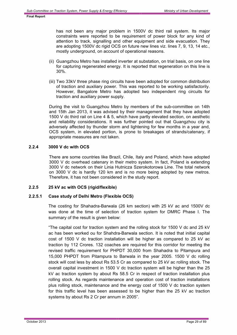
2.2.5.1 Case study of Delhi Metro (Flexible OCS)
The costing for Shahadra-Barwala (26 km section) with 25 kV ac and 1500V dc was done at the time of selection of traction system for DMRC Phase I. The summary of the result is given below:
“The capital cost for traction system and the rolling stock for 1500 V dc and 25 kV ac has been worked ou for Shahdra-Barwala section. It is noted that initial capital cost of 1500 V dc traction installation will be higher as compared to 25 kV ac traction by 112 Crores. 132 coaches are required for this corridor for meeting the revised traffic requirement for PHPDT 30,000 from Shahadra to Pitampura and 15,000 PHPDT from Pitampura to Barwala in the year 2005. 1500 V dc rolling stock will cost less by about Rs 53.5 Cr as compared to 25 kV ac rolling stock. The overall capital investment in 1500 V dc traction system will be higher than the 25 kV ac traction system by about Rs 58.5 Cr in respect of traction installation plus rolling stock. As regards maintenance and operation cost of traction installations plus rolling stock, maintenance and the energy cost of 1500 V dc traction system for this traffic level has been assessed to be higher than the 25 kV ac traction systems by about Rs 2 Cr per annum in 2005”.

Sub-Committee on Traction System, Power Supply & Energy Efficiency Ministry of Urban Development
Final Report
October 2013 Page 30 of 89
2.2.5.2 Case study of Delhi Metro (Rigid OCS underground corridor)
Requirement of higher tunnel diameter of 6.4 m was major cost issue for adopting 25 kV ac in underground corridor. However, with advancement of technology and adoption of international standard i.e. IEC and EN, when it became possible to adopt 25 kV ac traction system in a concentric tunnel diameter of 5.55m, techno-economic benefit shifted in favour of 25 kV ac traction system as can be seen from the chronology of events and techno-economic studies [14, 15, 31] carried out for Delhi Metro from 1989 to 2001 which are briefly given as under –
(i) In 1989 Railway Board prescribed adoption of 750 V dc, third rail for underground alignment of all Metro corridors including Delhi Metro.
(ii) In 1994, RITES techno-economic study brought out that 1500 V dc overhead rigid conductor system, is technologically superior and financially more attractive as compared to 750 V dc third rail. On examination, Railway Board advised RITES to carry out a further techno-economic study in respect of 25 kV ac system against 1500 V dc.
(iii) RITES examined, the world wide experience of 25 kV ac system of Paris, Swiss, Seoul and Euro-tunnel and brought out that in 25 kV ac system a finished tunnel dia of 6.4 m is required against 5.4 m for 1500 V dc traction system, involving additional cost of Rs 228 Cr whereas saving due to higher regeneration and other items worked to 25 Cr only and recurring savings 4,44 Cr and recommended 1500 V dc for underground of Delhi Metro and 25 kV ac for elevated.
(iv) In 1998, one man committee [14] appointed by DMRC brought out that 25 kV ac system with 6.4 m tunnel diameter is costlier than 1500 V dc by about Rs 90 Cr. However, if tunnel diameter could be reduced to 6.0 m, by adopting appropriate design, 25 kV ac would be cheaper than 1500 V dc by about Rs 50 Crores.
(v) In 1999, DMRC proceeded with 1500 V dc for the underground with the finished tunnel diameter of 5.4 m and 25 kV ac for elevated,
(vi) In March 2001 an another committee [15], on examination of latest technologies and other parameters brought out that 25 kV ac in a tunnel diameter of 6.2 m instead of 6.4 is feasible by adopting IEC and EN norms and is financially viable over 1500 V dc and mentioned that feasibility of adopting 25 kV ac in the underground has already been demonstrated by Korean railway administration and British Rail and their experience be take in to account in finalisation of designs.
(vii) In 2001, after award of contract of tunnelling for 5.4 m of finished diameter for 1500 V dc the contractor brought tunnelling machine which could give a finished tunnel diameter of 5.7 m at the same cost, with the concentric tunnel diameter of 5.55 m. General consultants and Principal Consultant (Electrical) of DMRC reviewed the design keeping in view the international standards (IEC and EN) and the development of 25 kV ac short insulator for the rigid OCS in Europe, brought out that 25 kV ac rigid OCS (similar to the one installed in Seoul) can be fitted in 5.55 m concentric tunnel with finished tunnel diameter of 5.7. With the tunnelling cost being the same as of 5.4 m diameter, the techno-economic

Sub-Committee on Traction System, Power Supply & Energy Efficiency Ministry of Urban Development
Final Report
October 2013 Page 31 of 89
balance shifter in favour of 25 kV ac traction system besides other benefits of higher regeneration, fewer number of traction substations, desirability of extension of traction system and common rolling stock. A saving of about Rs 76 Cr was estimated besides the above benefits.
(viii) In 2002, the Railway Board after examination of the proposal, approved adoption of 25 kV ac in a finished tunnel diameter of 5.7 m with concentric tunnel diameter of 5,55 m.
2.2.5.3 Requirement of higher tunnel diameter and carrying additional weight of transformers and front end converters were major issues in the past due to which 25kV ac traction system was not considered in the underground metros. However, as discussed above, with the development of modern design of track and advancement in technology of 25kV ac traction system, it has become possible to adopt 25kV ac it in concentric tunnel diameter of 5.55 m., higher tunnelling cost seizes to be an issue for adopting it in the underground metro. It is to be noted that higher tunnel diameter of 5.55m facilitates use of 3.2 m wide stock, which enhances passenger loading by 14%. In fact, Delhi Metro has decided to use 3.2 m wide stock on standard gauge in phase III and onwards. This has opened a new front and provided a viable solution for high capacity metros to the level of 75000 PHPDT and above. Needless to mention, adoption of 25 kV ac traction system helps in overall substantial reduction in capital investment and provides higher level of regeneration compared to 750/1500 V dc systems.
2.2.5.4 It needs to be noted that repeated experience has indicated that planned capacity
or forecasted capacity is soon run over in India and all Metros should be seeded with scalability. With several vendors available for all the components of 25 kV ac system, capex on infrastructure comes down. Also, the building blocks of an ac metro rolling stock being drawn from same pool from which sub-systems for sub-urban/EMUs are drawn, despite additional transformer, cost of the stock compares competitively. Further, higher possibilities of all day regeneration, without use of any energy storage devices exists. This along with substantially reduced line losses drives down the opex. Further, it would be worth mentioning that beyond a PHPDT of 80,000 the traction system ceases to be a constraint.
2.2.5.5 Delhi metro has adopted 25 kV ac on their existing 164 km network with 43 km
underground portion. Even Seoul metro on their Kawchon line has adopted 25kV ac.
2.3 Study of Current / Future Trends (Metros built in last 5 years) 2.3.1 Based on information available through internet [1-9], list of Metros which were
commissioned in the last five years has been prepared and is placed at Annexure IV. This annexure contains information about commissioning date, network length, number of stations, track gauge, traction system and some special features of recently commissioned metros. The table below summarizes Annexure IV:

Sub-Committee on Traction System, Power Supply & Energy Efficiency Ministry of Urban Development
Final Report
October 2013 Page 32 of 89
Table 6 System Location Number of
locations 750 V dc with OCS Adana (Turkey)
1
750 V dc with third rail Algiers (Algeria), Almaty (Kazhakstan), Bangalore (India), Perugia (Italy), Shenyang (China), Suzhou (China), Xian (China), Mashshad (Iran), Dubai (UAE)
9
1500 V dc with third rail Gunagzhou (China), Shenzhen (China)
2
1500 V dc with OCS Chengdu (China), Kaohsiung (Taiwan), Kunming (China), Mecca (Saudi Arabia), Palma-de-mallorca (Spain), Santo Domingo (Dominican Republic), Seattle (USA), Seville (Spain)
8
25kV ac 50 Hz OCS Delhi Metro (India) 1 2x25kV ac 60 Hz OCS Sin Bundang line (Seoul Subway) 1 Total 22
2.3.2 750V dc
It can be seen from Annexure IV that, over 58% of Metros have been commissioned with 750 V dc out of which less than even 1% network is with OCS. Germany, Turkey, USA, Greece, Philippines, Canada and some South East Asian countries are adopting 750V dc system in their ongoing construction of medium capacity metros.
2.3.3 1500 V dc
From Annexure IV, it can be seen that 29% network length of Metro have been commissioned on 1500 V dc out of which 46% is with third rail. 1500 V dc third rail have been commissioned only in China on Guangzhou metro (Line 5) and Shenzhen metro (Longgang line).
2.3.4 25 kV ac with OCS
Delhi Metro has commissioned Line-4, Line-5, Line-6 and Airport Express Line on 25kV ac traction system during 2010 & 2011 with a total network length of 54.18 km. This system is also under implementation/planned for implementation in the following metros:
Delhi Metro Phase III 140 km Chennai 43 km Hyderabad 72 km Jaipur Metro 9 km
In Australia, Adelaide Metro is planning to adopt 25 kV ac traction in future.

Sub-Committee on Traction System, Power Supply & Energy Efficiency Ministry of Urban Development
Final Report
October 2013 Page 33 of 89
2.3.5 2x25kV ac traction system
Seoul Metro of South Korea on Sin Bundang line has commissioned 17.3 km. on 25kV ac traction on 28th October 2011. Seoul metro of South Korea has also decided to go for 2x25 kV ac traction systems in some of their future projects.
2.4 Merits and Demerits of various traction systems 2.4.1 600-850V dc third rail traction system 2.4.1.1 Merits 2.4.1.1.1 Aesthetics
In the absence of any overhead conductors and supporting structures, the 750V dc Third Rail System offers the best ‘aesthetic’ solution, particularly on the surface/elevated portions, compared to the Overhead Catenary System.
Overhead Catenary System Third Rail System
From the pictures above, it can be seen that in the case of overhead traction, the skyline gets obliterated whereas the skyline is clear in a third rail system. Issue of aesthetics, however, is a tenuous one in decision making matrix. Tourism centric country like Switzerland is principally on OCS. Also, trolley buses and trams recognized as mainstay of sustainable urban transport solution, have been using street level OCS and are infact taken as signatures of a city. Japan also has adopted OCS for all its mass transit needs. Given the wide spread acceptance of OCS globally and the stressed urban conditions in India requiring Metro rail- a long term view needs to be taken on the issue of aesthetics.
2.4.1.1.2 Low tunnelling costs
Since there is no requirement of maintaining overhead clearances, a third rail system can be accommodated in a tunnel diameter lower than the overhead catenary systems, leading to reduced cost of tunneling.
2.4.1.1.3 Low wear and tear
This system is oldest and extensively used in various World Metros. The third rail per se needs very little maintenance since by virtue of its solidly rigid design it is able to withstand passing of current collector devices of the trains without any significant wear and tear. The Aluminium conductor rail with a top cladding of stainless steel is expected to give a life in excess of 60 years.

Sub-Committee on Traction System, Power Supply & Energy Efficiency Ministry of Urban Development
Final Report
October 2013 Page 34 of 89
2.4.1.1.4 Low maintenance requirement and established maintenance practices
Having evolved over the last more than 100 years, 750 V dc system with third rail is time tested due to availability of considerable experience in installation and O&M. By the inherent nature of design of the third rail, the effect of wind and rain on the third rail is minimum and on account of the low height of the third rail, there is always easy access for maintenance. However maintenance of substation costs more as they are more in numbers.
2.4.1.2 Demerits 2.4.1.2.1 Operational constraint imposed by Bridgeable and non-bridgeable Gaps
The power supply from the overhead wire is normally continuous but in third rail system it is physically broken at crossovers to allow passing of trains on deviated track without damage to the collector shoe. These third rail breaks or gaps, as they are called, impose certain constraints in the form of compatibility of the type of third rail ramps and type of turnouts to maintain bridgeable gaps and requisite speed. Gaps, where at least one Current Collector Device on a coach remains in contact with the third rail, is called a bridgeable gap. Where both Current Collector devices of a coach, lose contact with the third rail, there is a temporary loss of power. Such gaps are called non-bridgeable gaps. This restriction can be overcome by inter-connecting the current collector devices on various coaches by a cable known as bus-line but this adds to the cost of the coaches since the use of inter-vehicular power couplers becomes essential. Conductor rail gaps are also provided at the substation feed for facilitating sectioning and maintenance.
2.4.1.2.2 High operating currents and high voltage drops necessitating reduction in spacing
of sub-stations
Because of the comparatively lesser voltage, a 6-car rake handles much larger current of the order of 6,000 Amp. This leads to larger voltage drops along the Third Rail distribution system, which necessitates closer spacing of sub-stations at an interval of almost every 2 km, leading to higher costs of construction. The sub-station capacity is small and is of the order of 2X3 MVA requiring lesser space per substation. In order to reduce voltage drop on line where substation spacing are more, third rail requires paralleling at suitable points by installing track cabins which also adds to the cost of electrification. However, metros like BMRCL, Bangkok, Dubai have not adopted track cabin with substation spacing of 1.5 km.
2.4.1.2.3 Low levels of regeneration
In a 750V dc third rail system, the probability of having a train braking and a train accelerating close enough to each other to allow for an effective transmission, is less compared to systems with higher voltages. Even due to rise in voltage during re-generation, sometimes the voltage automatically cuts off and no recovery takes place. To improve the power recovery during regeneration, the sub-stations are required to be equipped with inverter units for transfer of power to grid or provision is required to be made for energy storage units. As per RITES report hardly 60% of re-generated energy in a 750 V dc system is possible to be retrieved. Even UIC, in one of the recent papers on regeneration in dc metro system, indicates 50% retrieval of regenerated energy without adopting any additional technology.

Sub-Committee on Traction System, Power Supply & Energy Efficiency Ministry of Urban Development
Final Report
October 2013 Page 35 of 89
2.4.1.2.4 Safety hazard with use of high voltage at ground level
Due to existence of the ‘live’ third rail at ground level, this system can be hazardous to safety of commuters and maintenance personnel if they fail to adopt safety precautions. Top current collection system is considered more hazardous and many a times current collection suffers due to contamination on third rail.
2.4.1.2.5 Phenomenon of stray current
In a third rail system, where the running rails are used as a return path, a part of the return current leaks into the track structure. This current is called stray current. It is necessary to manage the stray current to ensure minimal corrosion effect and consequent damages to metallic components in the track structure as well as metallic reinforcement and metal pipes of buildings of metro and public areas adjacent to the Metro alignment. On the London underground, which is among the oldest metros, has gone in for a fourth rail system for the purpose of eliminating stray current, with the fourth rail serving as return conductor instead of the running rails. Stray currents continue to be singular [10], biggest anxiety issue with dc traction. This entails expensive supervision and monitoring equipment. Further, system needs very careful maintenance strategies to keep close watch on the stray currents. The key element of risk stems from the irreversible loss to the structure reinforcement [11], which can extend beyond the limits of metro authority to adjoining municipal and civil construction/infrastructure. The stray current induced damage is hidden and irreversible. It is to be noted that in dc systems the load currents and fault currents are of the same order and with very few options of fault discrimination, the level of vigil while operating the network is much higher. Further, unlike a magnetic voltage transformation in ac systems, dc supply systems suffer from few possibilities of operating under overloads as semiconductor based rectifiers need to be sized from the day one and can’t tolerate overloads. However, network and operational planning can mitigate this fundamental drawback. With track fastener insulation, the stray current problem is mitigated. However, the insulation has a life and would need replacement, periodically. This issue relates to dc traction in general irrespective of voltage level.
2.4.1.2.6 Line losses are more due to higher current. As per report T950 of RSSB UK [17],
transmission line losses on 750V dc traction system are around 21% as against 5% of 25kV ac traction system.
2.4.2 1500 V dc system with Overhead Catenary System 2.4.2.1 Merits 2.4.2.1.1 Higher throughput compared to 750 V dc system
1500V dc catenary system has been adopted by many metros in the world on comparative cost economics reasons compared to 750 V dc and to meet traffic level requirement in excess of 50,000 PHPDT (e.g. Hong Kong, Spain, Korea, Guangzhou etc.).
2.4.2.1.2 “Lower initial investment, line losses” and higher level of regeneration as
compared to 750V dc third rail

Sub-Committee on Traction System, Power Supply & Energy Efficiency Ministry of Urban Development
Final Report
October 2013 Page 36 of 89
2.4.2.2 Demerits
The demerits are as under: 2.4.2.2.1 Higher maintenance requirement and costs as compared to 750V dc third rail
system 2.4.2.2.2 Problem of stray current associated with dc traction systems as discussed in para
2.4.1.2.5 2.4.2.2.3 Theoretical traffic capacity with 1500V traction system is less as compared to 25
kV ac system, although beyond 75000 PHPDT, the other issues become the constraint and not the traction system. RATP RER Metro France, has achieved a maximum 77000 PHPDT, on their 1500 V dc catenary system, as per recent Nova report.
2.4.2.2.4 OCS system can be prone to the effects of thunderstorm, lightening and intrusion
by birds and animals, if appropriate measures are not taken. 2.4.2.2.5 Line losses are more due to higher current as compared to 25kV ac. It may be in
the range of 10 to 12% as against 5% of 25kV ac system. 2.4.2.3 Merits of 1500V dc third rail over OCS 2.4.2.3.1 1500V dc third rail system requires less maintenance and its easily accessible,
being at ground level. Its performance is also not affected by wind/storm and intrusion by flying objects/birds.
2.4.2.3.2 As per experience of Guangzhou Metro, Tunnel size is comparable in third rail vis-
à-vis OCS system for 1500V dc system. 2.4.2.3.3 Since no conductors are visible above the train, the third rail system is
aesthetically superior. 2.4.2.3.4 Track maintenance cost, as per experience of Guangzhou Metro, is comparable in
third rail and OCS system. 2.4.2.4 Demerits of 1500V dc third rail over OCS 2.4.2.4.1 Due to existence of live third rail that too at 1500V at ground level, it can be
hazardous to safety of commuters and maintenance personnel if they fail to adopt safety precaution.
2.4.2.4.2 Initial investment in third rail system is higher as compared to OCS, however it is
comparable with ROCS. 2.4.2.4.1 Power shut down and earthing is necessary for taking up any maintenance activity
of track, signal etc. in the viaduct as well as in the tunnel. During emergency evacuation of passenger it is essential to make third rail dead before allowing passengers to detrain enroute.

Sub-Committee on Traction System, Power Supply & Energy Efficiency Ministry of Urban Development
Final Report
October 2013 Page 37 of 89
2.4.3 25 kV ac with OCS (flexible/rigid) 2.4.3.1 Merits 2.4.3.1.1 Capacity: The system can cater to traffic needs even in excess of 75000 PHPDT,
which, however, is restricted on account of other constraints. 2.4.3.1.2 Reduced cost: Unlike dc traction this system, does not require substations at
frequent intervals due to high voltage, reduced current levels and lower voltage drops as a result, there is substantial reduction in costs.
2.4.3.1.3 Ease of capacity enhancement
Capacity enhancement can be easily achieved by simply enhancing the transformer capacity and its associated equipment at the receiving substation. Hence the system provides tremendous flexibility of operation. In the case of dc systems, equipment at all Traction Substations enroute would need to be up-rated for any capacity enhancement, which would be difficult to implement and involve high costs. As a matter of fact, in dc systems, to enhance capacity, there may be necessity of adding sub-station which sometimes may not be feasible and even otherwise it would be practically impossible to provide on an operational line.
2.4.3.1.4 Higher efficiency of operation
The efficacy of regeneration is substantially more than dc systems and line losses are very less of the order of 5%. The regenerated energy has always a consumer in the large feeding zone and receptivity is also there due to higher voltage. 100 % recovery of regenerated energy is possible in the case of 25 kV ac traction compared to a figure of 75 % in the case of 1500 V dc systems and 60 % in the case of 750 V dc systems as per report of RITES (1998).
2.4.3.2 Demerits 2.4.3.2.1 Higher tunnel size
In order to maintain the minimum prescribed clearances, the tunnel diameter in 25 kV systems is higher than that required for 750V dc third rail system which adds to the cost in the underground section. However, higher tunnel diameter needed for 25 kV ac also facilitates use of 3.2 m wide stock.
2.4.3.2.2 Higher train weights, train costs and associated energy consumption
(i) Since ac traction system calls for provision of transformers and front end
converters, the train cost could be more for 25 kV ac traction as compared to dc traction. The weight of 6-car 25kV ac train increases by 5% due to these additional equipment which also increases energy consumption.
(ii) Suitable measures are required for mitigation of EMC/EMI caused by single
phase 25 kV AC traction systems. Hence there is an additional cost for implementation of EMC/EMI measures.
(iii) High maintenance requirement compared to third rail systems. Further, OCS
system can be prone to thunderstorms, lightening and intrusion by birds and animals if appropriate measures are not taken.

Sub-Committee on Traction System, Power Supply & Energy Efficiency Ministry of Urban Development
Final Report
October 2013 Page 38 of 89
(iv) The requirement of clearances for Overhead Power line crossings of the State Government Power Supply authority is more in the case of AC traction which would have additional cost implications. However, it is felt that power line crossing issue is largely independent of type of traction system and there is need to rationalize various governing statutes, which can possibly lead to faster execution and further economies would accrue as a result.
2.5 Technical feasibility of different traction systems and their
relationship with peak hour peak direction traffic (PHPDT) 2.5.1 An independent study has been carried out to evaluate the number of passengers
that can be transported in one direction during peak hours on 750V dc and 1500V dc. It is concluded from the report placed at Annexure V that 750V dc traction system can at the most cater to the peak traffic of 48000 PHPDT with a TSS at every alternate station. This has been practically established as Moscow Metro has achieved maximum PHPDT of 53000 on 825V dc traction system as per NOVA report.
2.5.2 The study further reveals that with 1500 V dc system, it is possible to achieve
PHPDT of 75000 and even above. Review of data available for Metro systems world over also indicates that 1500 V dc system has been selected for a designed PHPDT of 75000. As per Nova report, RATP RER Paris has achieved maximum PHPDT of 77000 on 1500 V dc system.
2.5.3 The study summarizes that 1500 V dc and 25 kV ac systems do not pose any
constraint on carrying capacity upto 75000 PHPDT. Beyond 75000, 25 kV is the best technical option, even though for such capacities, other systems become constraint and not the traction system.
In fact the design criteria in dc traction system can be reviewed based on experience of other world metros. The current design criteria of “full outage of a TSS and traffic remain normal” is conservative and can be examined and modified to “outage of one rectifier of a TSS and traffic remain normal”. This will reduce the number of traction substations by about 20% and overall traction system cost reduction by 5-7%. Implementation of this scheme needs further detailed study.
2.6 Economic Viability and Sustainability: Analysis of capital cost of
various traction systems for different levels of traffic
2.6.1 Direct cost of traction systems based on experience of past 5-10 years of Indian metros and Indian Railways
2.6.1.1 Before making an attempt to analyze the costs of various type of traction power
system, it is worthwhile mentioning the following facts about it:
2.6.1.1.1 The maximum power requirement, which contributes to the cost of the traction power system, is dependent on:
(i) the Peak Hour Peak Direction Traffic (PHPDT), (ii) performance requirement and level of technology of rolling stock, (iii) loaded train weight, (iv) headway between the trains, (v) Rake composition of trains,

Sub-Committee on Traction System, Power Supply & Energy Efficiency Ministry of Urban Development
Final Report
October 2013 Page 39 of 89
(vi) track geometry and (vii) efficacy of the regeneration.
2.6.1.1.2 The cost of the traction power system shall depend upon following:
(i) Maximum power to be transmitted to meet traffic requirement (ii) The level of redundancy e.g., the number of transformers being provided for
the traction and auxiliaries, and its cabling arrangement (iii) Market for a particular type of technology, volume of requirement and orders
already available with the manufacturers. (iv) Requirement of HT and LT cable and number of gas insulated substations
(GIS)
2.6.1.1.3 It is, therefore, worthwhile to consider Technical Feasibility, Economic Viability, Aesthetics and Sustainability besides costs, while selecting a traction system. Additional considerations could be Reliability, Operation and maintenance requirement and Upcoming technologies. Each system, be it 750 V dc, 1500 V dc or 25 kV ac has its merits and demerits and a decision with regard to the adoption of a particular system in preference to the others would be based on these considerations.
2.6.1.1.4 However, since the initial cost is one of the important considerations while deciding
the type of traction system it has been discussed in detail in ensuing paragraphs.
2.6.1.2 750 V dc system 2.6.1.2.1 Following two metros in India are using 750 V dc system with third rail today:
• Kolkata Metro – revenue services introduced in 1984 • Bangalore Metro – revenue services introduced in 2011
2.6.1.2.2 There are major differences between the two systems as detailed hereunder:
(i) Steel third rail with top contact has been used in Kolkata Metro whereas an
aluminium composite third rail with bottom contact has been adopted in Bangalore Metro.
(ii) Barring recently introduced new rakes; Kolkata Metro trains are not air-conditioned. Instead, the tunnel itself is air-conditioned and hence power consumption for the auxiliaries is quite different as compared to modern metros.
(iii) Regenerated energy in existing Kolkata Metro trains is not utilized by other trains and hence it is wasted in resistor which further increases the load of air-conditioning of tunnel.
2.6.1.2.3 Bangalore Metro Rail Corporation Ltd
The total cost of traction system of BMRCL is Rs.498.51 crores for network length of 42.3 km, which includes the cost of depot and auxiliary system as per order of December 2009 on M/s ABB.This has a PVC clause for power transformer, 33 kV switchgear, conductor rail and 33 kV/ 750 V cable. Therefore, cost per km. will be Rs.11.78 crores and considering inflation rate of 5%; its present day cost per km. comes out to be Rs.13.55 crore.

Sub-Committee on Traction System, Power Supply & Energy Efficiency Ministry of Urban Development
Final Report
October 2013 Page 40 of 89
Out of the total traction system cost of Rs. 498.51 crores, the cost of auxiliary system is Rs.125.13 crore. The cost of auxiliary system includes cost of ASS transformers and switchgear items, 33 kV cables related to auxiliary circuits, cost of RSS apportioned @ 40 % to auxiliaries. The cost of auxiliary system per km. is, therefore, Rs.2.96 crore. Thus the cost of the auxiliaries is about 25% of the total cost. Bangalore Metro has only 8.8 km of underground section, where higher capacity of auxiliary transformers of 2000 kVA against 500 kVA have been used.
2.6.1.2.4 Kolkata Metro Rail Corporation Ltd.
Contract of Kolkata metro for traction and auxiliary system was finalized in Dec 2010 for Rs.174.63 crores for network length of 14.58 km and hence average cost per km comes out to be Rs. 11.98 crores. Considering inflation rate of 5% per annum current rate per km. comes out as Rs.13.18 crore.
2.6.1.3 1500 V dc system
DMRC, at one point of time had awarded a contract for 1500 V dc traction system for Vishwavidyalaya to Central Secretariat Section, which later on was electrified on 25 kV a system. It has been observed that the cost of 25 kV ac system was almost Rs.1 crore per km less as against rates offered for 1500V dc system. Considering the present day cost of 25 kV ac system as Rs.9.51 crore per km for the elevated corridor and Rs.11.26 crore per km for the underground corridor, the cost of 1500 V dc traction system works out to Rs.10.51 crores per km for the elevated corridor and Rs.12.26 crore per km for the underground corridor.
2.6.1.4 25 kV ac traction 2.6.1.4.1 Case of Chennai Metro
25 kV AC Traction System is being used in Chennai Metro Rail Limited on Corridor 1 & 2. In elevated section flexible overhead catenary system and in underground rigid overhead catenary system are being adopted. The cost of CMRL is based on order dated 25/1/2011 placed on the consortium of M/s Siemens AG and M/s Siemens Transportation India.
The total cost for Design, Built, Commissioning and including spares and training is Rs. 252,96,07,952 and EURO 83,73,262. Equivalent rupees value is 304,43,33,322/-. Cost per km works out to be Rs. 6.76 crores.
Table 7
Corridor U/G kms Stations Elevated kms
Stations Total Kms
1 14.3 11 8.785 7 23.085 2 9.695 9 12.266 9 21.961 TOTAL 23.995 20 21.051 16 45.046
Considering inflation rate of 5% per annum, present day cost per km. becomes Rs.7.44 crore. These rates are quite less compared to DMRC and Hyderabad metro apparently due to less requirement of cable and GIS. Further, it is worthwhile to mention that this project is yet to be completed and the contract has many PVC clauses and therefore the final cost is expected to be more.

Sub-Committee on Traction System, Power Supply & Energy Efficiency Ministry of Urban Development
Final Report
October 2013 Page 41 of 89
2.6.1.4.2 Case of Delhi Metro
The cost of traction system including auxiliaries is Rs. 7.3 crores per km for elevated sections and Rs. 8.7 crores per km for underground corridoras per last executed project of phase II. The orders for DMRC Phase II for elevated section was placed in Feb, 2007 and for Underground in Sept,2007 with PVC clause on transformer, 25/33 kV switchgear. Based on this, the current cost of traction system including auxiliaries comes out as Rs.9.51 crore for the elevated corridor and Rs.11.26 crore for underground after considering inflation of 5% per annum.
The estimated cost of auxiliary system is around 25- 30 % on the elevated and 35 – 40 % in the underground section. This is based on Phase-II contract awarded in February/September 2007 and after considering simple inflation of 5% per annum. The current cost of underground rigid OCS is Rs.1.75 Cr more per route km. after considering inflation.
2.6.1.4.3 Case of Hyderabad Metro
M/s. Larsen & Tubro have finalized contract of 25kV ac OCS system for elevated corridor of 72 km. of Hyderabad Metro in July 2012 for a total value of Rs. 643 crore. This has a PVC clause for transformer and switchgear. The average cost per route km., therefore, is Rs.8.93 crore. The present day inflated cost per km. will be Rs. 9.15 crore.
2.6.1.5 Comparison with Indian Railways’ Electrification Cost 2.6.1.5.1 The present electrification cost of Indian Railways including cost of substation per
route km is Rs.1.20 crore, which, however, can vary depending upon the length of the transmission line involved in the project. After detailed study, it has been found that metro rail electrification involves following additional features, which increases the cost substantially as compared to Indian Railways:
2.6.1.5.2 Metro electrification uses costly buried cables for transmission of power, which
passes through densely populated area. 2.6.1.5.3 Inter substation spacing is only around 15 km. as against 50 km. of IR and even
substation capacity is almost double to cater to high level of passenger traffic. 2.6.1.5.4 Gas insulated substations (GIS), which are quite costly, are quite often used in
metro due to limitation of space in heavily populated area 2.6.1.5.5 Metro provides mast in span length of 27 to 45 meter as against 63 meter of IR
due to curve and gradients.
On 25 kV ac metro system, rigid OCS in the underground and higher conductor size of 150 sq.mm increases the cost of electrification by almost 10 % compared to the conductor used on Indian Railways. Third rail cost is almost 15 % of the total cost of 750 V traction systems.
2.6.1.5.6 Use of high reliable fittings, special type of neutral sections, gas ATD at critical
location, overhead protection cable (OPC), return conductor (RC) and booster transformer (BT), earthing and bonding further increases the cost of electrification in metro system.

Sub-Committee on Traction System, Power Supply & Energy Efficiency Ministry of Urban Development
Final Report
October 2013 Page 42 of 89
2.6.1.5.7 The cost of depot electrification and the cost of capital spares are included in the cost of electrification in a metro system – the contribution of these two factors is about 12 % of the total cost of electrification in a Metro system.
2.6.1.5.8 Auxiliary power supply arrangement, which is a specific requirement of metro
system increases cost of electrification by 30 to 35%.
In view of the above reasons, it would not be appropriate to compare the cost of electrification of metro system with that of Indian Railways.
2.6.1.6 Summary of Electrification Cost 2.6.1.6.1 Based on the above information, summary of costs of electrification of various
metros of India along with the designed PHPDT is given in the following table:
Table 8 Summary of costs and designed PHPDT
System Location Present cost per km crores Rs.
Designed PHPDT
750 V dc with third rail
BMRCL 13.55 48000
750 V dc with third rail
KMRCL 13.18 48000
1500 V dc with OCS
Order placed by DMRC for VV to CS and later on switched over to 25kV ac
10.51 (12.26 for underground corridor)
60000
25 kV AC with OCS
DMRC 09.51 (11.26 for underground corridor)
60000
25kV ac with OCS
CMRL 7.44 60000
-do- Hyderabad metro 9.15 60000 2.6.1.6.2 From the above table, it can be inferred that the average cost of electrification per
km. for elevated corridor for 25kV ac traction system can be considered as Rs. 9.32 crore and for 750V dc traction system, Rs.13.36 crore. The cost of electrification per km. on 25kV ac traction system for underground corridor can be considered as Rs.11.20 crore. The cost of 25kV ac system has been estimated by taking average of DMRC and Hyderabad metro cost but cost of CMRL has not been considered as it is quite low for the reasons explained earlier. On the other hand, cost of 750V dc system has been estimated by taking average of present day cost of BMRCL and KMRCL. These costs shall be used for assessing the economic viability of a sample corridor.
2.6.2 Direct cost of rolling stock
2.6.2.1 General
The direct comparison of the per coach cost will not be meaningful, since there are differences in the rolling stock on account of the following major factors: (i) Performance parameters (ii) Gauge adopted (iii) Track geometry, curvatures, grades etc.

Sub-Committee on Traction System, Power Supply & Energy Efficiency Ministry of Urban Development
Final Report
October 2013 Page 43 of 89
(iv) Carrying capacity/axle weight (v) Coach Dimensions (vi) Number of powered axles in a train consist The cost of rolling stock is also influenced by the following fcators: (i) Number of coaches (ii) The specifications viz. acceleration, deceleration, scheduled speed, special
features required which are entirely not the same in above cases. (iii) DC link voltage (iv) Commercial Conditions: defect liability period, indigenization clauses, price
variation, delivery period, time frame for completion, ambient conditions, etc. (v) Risk factors perceived by the bidders BMRCL trains have an acceleration of 1.0 m/sec.2 with 67% powered axles while DMRC/CMRL trains have an acceleration of 0.82 m/sec.2 with 50% powered axles. DMRC in Phase III and IV have planned for 1 m/sec
2 acceleration and 67% powered axle. DMRC coach width is 2.9 m for SG stock of Phase II, 3.2 m. for BG stock and Phase III and IV SG stock as against BMRCL/CMRCL/KMRC/HMRL of 2.88 m. However for an appreciation, the cost per coach as they stand today is given as under. Initially the report was prepared by considering the cost per coach of different metros based on the date of purchse order and thereafter escalation at the rate of 5% per annum. However, on receipt of comments from MD/BMRCL and discussions amongst the members on 23rd July 2013, it was decided to consider the ordered price at the mid value of the contract considering exchange rate of that day and taking in to account taxes & duties alongwith deemed export benefits.
2.6.2.2 Bangalore metro coach cost
The cost of 750 V dc coach is based on orders placed by BMRCL on M/s BRMM. The orders were placed in February 2009 for 150 coaches and value of the order is Rs. 1478 crores with taxes. The cost per coach of BMRCL with taxes and duties on the mid period of the contract is Rs 10.3 Cr including spares and its estimated cost on 31st December 2012 with deemed export benefit of 10% comes out to be Rs 9.99 Cr. including spares.
2.6.2.3 KMRCL metro coach cost
KMRCL has placed an order of Rs. 777 crore including spares on M/s. CAF Spain for supply of 84 metro coaches in June 2012. The estimated cost as on 31st December 2012 is Rs 9.29 Cr including spares and escalation of 5% per annun. It is to mention that KMRCL has PVC clauses for 66 % of their supply component with no clamping limit. The order is yet to be executed and the final prices are expected to be higher than this. The estimated Rs 9.99 Cr cost including spares per coach of Bangalore metro is higher as compared to KMRCL although their order was placed in 2009 mainly due to different commercial conditions and they have procured 3-car trains with composition of DTC+MC+DMC as against 6-car rake of KMRCL with composition of DTC+MC+MC+MC+MC+DTC.
2.6.2.4 Chennai metro coach cost 2.6.2.4.1 The manufacturing order for building of rolling stock has been placed on M/s.
Alstom on 2nd August 2010. The value of the contract is Rs. 513.77 crore and

Sub-Committee on Traction System, Power Supply & Energy Efficiency Ministry of Urban Development
Final Report
October 2013 Page 44 of 89
EURO 16.88 crore which works out to Rs. 1471 crore, which includes spares for manufacture of 168 coaches. The mid price including spares per coach with taxes and duties of CMRL is Rs 9.19 Cr. The estimated cost including spares per coach of CMRL with taxes and duties and also with 6% deemed export benefits on 31st December 2012 are Rs 8.74 Cr.
2.6.2.4.2 It is to mention that CMRL has PVC clauses for their supply component. The order
is yet to be executed and the final prices are expected to be higher than this. 2.6.2.4.3 In Chennai Metro, the number of powered axles in a rake is only 50%, whereas in
BMRCL, it is 67%. As a result, the acceleration achieved on the BMRCL rake is 1.0 m/sec2 as against 0.82 m/sec2 on CMRL. While comparing the costs, this superior operating performance of the BMRCL rake has to be kept in mind.
2.6.2.5 DMRC metro coach cost
Average per coach cost at mid value of the contract (August 2009) of RS 2 stock (3.2 m BG stock) is Rs. 7.88Cr (Year 2007) and that for RS 3 stock (2.9 m wide SG stock), it is Rs. 9.996Cr with taxes (Year 2007). The cost of Phase III rolling stock with taxes & duties for which the orders were placed on 1st April 2013 is Rs 9.86 Cr. The prices per coach of RS 10 with deemed export benefits of 13% comes out to be Rs 8.58 Cr as on 1st April 2013. It is to be noted that cost per coach of rolling stock for all the phases of DMRC includes cost of spares. DMRC stock of Phase III is similar to BMRCL in performance requirement and will provide acceleration of 1 m/sec2 with 67% powered axle but its coach width is 3.2 m. as against 2.88 m of BMRCL.
2.6.2.6 Larsen and Toubro Metro Rail, Hyderabad Ltd
Larsen and Toubro Metro Rail, Hyderabad Ltd. have awarded contract to M/s Hyundai Rotem for supply of 171 metro cars (57 trains) for a total value of Rs.1750 crorewhich includes cost of spares and taxes & duties in the month of September 2012. It may be worth mentioning that the order of Hyderabad Metro for rolling stock is on the basis of firm price and has no linkage with the exchange rate and remains the same throughout the contract period. Thus the average cost per coach including spares with taxes & duties is Rs 10.23 Cr. It is to be noted that Hyderabad metro will run 3-car trains similar to Bangalore Metro and they also have 67% powered axle. They have a rake composition of DTC+MC+DMC similar to Bangalore metro. It is given to understand that due to certain tax benefits to Korean supplier, the overall taxes are less for M/s. Hyundai Rotem.
2.6.2.7 Cost comparison of 1500V dc rolling stock with 25kV ac rolling stock as per DMRC tender experience:
2.6.2.7.1 All parameters being the same, the cost of ac rolling stock should be more than the dc rolling stock because the propulsion equipment of the ac rolling stock comprises of two additional major equipment, viz. transformer and front end converter.
2.6.2.7.2 Examination of quotes received by DMRC in 2000, for AC and DC rolling stock of same performance requirement in the RS-1 tender shows that the cost of 25 kV ac rolling stock is more than 1500 V dc rolling stock by Rs 37 lakhs, ie by 9% However advancements in technology like use of higher dc link voltage and single

Sub-Committee on Traction System, Power Supply & Energy Efficiency Ministry of Urban Development
Final Report
October 2013 Page 45 of 89
transformer for multiple motor coaches are now resulting in reduction in cost of ac rolling stock. The difference in 25 kV ac vis-à-vis 750 V dc rolling stock would be much lower than 9%.
2.6.2.7.3 Even though cost data across various contracts cannot be compared on a one-to-one basis, it is seen that the cost of dc rolling stock and ac rolling stock are comparable.
2.6.2.8 Summary of RS costs
Based on above, the summarized costs of metro coaches as on 31st December 2012,which includescosts of spares and taxes and duties of different Indian Metros are given in the following table:
Table 9
Current cost of metro coaches of different Indian Metros SN Type of
traction Name of Metro
Estimated cost per coach (Rs. In cr) with taxes & including export benefits as on 31st Dec 2012
Estimated cost per coach with spares without taxes and without export benefits as on 31st December 2012
Remarks
BMRCL**
9.99 9.41 2.88m. wide, 1.0m/s2, 67% motored axle, certain better features compared to KMRCL
1 750V dc
KMRCL
9.29 8.05 2.88m. wide, 1.0m/s2, 67% motored axle, flexible PVC clauses for 66% component without any clamping.
CMRL 8.74 8.28 2.9m wide, 0.82m/s2, 50% motored axle, flexible PVC clauses for 66% component without any clamping.
DMRC** RS2 9.26 8.73 3.2m wide, 0.82m/s2,
50% motored axle RS3 10.09 9.97 2.9m wide, 0.82m/s2,
50% motored axle Phase III (RS10)
8.58 (1st Apr 2013
7.91 3.2m wide, 1.0m/s2, 67% motored axle, more energy efficient
2 25kV ac
Hyderabad** (HMRL)
10.23* 8.77 2.9m. wide, 1.0m/s2, 67% motored axle,

Sub-Committee on Traction System, Power Supply & Energy Efficiency Ministry of Urban Development
Final Report
October 2013 Page 46 of 89
*Unlike other Metros, this figure is firm price with no variation due to exchnage rate throughout the contract period and also without any deemed benefit. **PVC clauses in respect of DMRC, BMRCL and HMRL have lower flexible component with a fixed clamping of 3%, unlike, KMRCL and CMRL.
Technically, the size of traction motor and other associated equipment depends upon dc link voltage. In case of 25 kV ac, it is possible to have higher dc link voltage, which reduces the size of the traction equipment and may accordingly influence the logical cost. 1500 V dc system also permits higher dc link voltage compared to 750 V dc-but is limited to lowest permissible supply voltage for unregulated dc link design (else a booster chopper is needed). Many of the subsystems are manufactured by the overseas suppliers. A few manufacturers have set up plants for manufacturing of a few sub-systems in India during last 7-8 years.
2.6.2.9 From table 9 it is seen that the cost of ac and dc stock are comparable although based on DMRC’s experience of Phase I, 1500V dc rolling stock is about 9% less costlier as compared to 25kV ac.The propulsion equipment forms nearly 20-25% of the cost of rolling stock and this gets influenced in 3-phase drive systems by the additional equipment required in 25 kV ac (traction transformer and converter) and in dc the size of the traction equipment because of lower permissible dc link voltage as compared to higher permissible dc link voltage in ac stock. With insistence on progressive indigenization in present and future procurements, the cost of rolling stock used on 750 V dc as well as 25 kV ac can be expected to
come down.
2.6.3 Weight reduction of rolling stock, consequent energy savings and impact on operating cost
Weight comparison (in tonnes) between various types of rolling stock used by DMRC and BMRCL is given in the following table:
Table 10
A direct comparison of weight may not be very meaningful due to the following differences in the rolling stock: (i) Carrying capacity
(ii) Coach dimensions particularly widths
(iii) The number of motored axles in a train consist
(iv) Buffing load
DTC MC TC DMC RS1 40.12 40.5 - - RS2 41.74 41.73 39.42 - RS3 40.98 40.96 - - BMRCL - 37.48 36.61 38.43 CMRL 40.85 42.20

Sub-Committee on Traction System, Power Supply & Energy Efficiency Ministry of Urban Development
Final Report
October 2013 Page 47 of 89
(v) Performance requirements
(vi) Track geometry
Rolling stock of dc traction system would definitely have a weight advantage due to absence of a transformer and front end converter which is required for converting the ac secondary voltage to a stable dc link voltage in case of ac traction. These items are not required on a dc based system as the supply voltage can be fed directly to the dc link. 25kV ac system has, however, inherent advantage that it can use dc link of higher voltage to that of 750V dc system, as a result, weight of inverter, traction motors and cables will be less. In case higher dc link is adopted in dc traction system, it would require booster chopper which also adds weight and cost. The transformer and front end converter would make a weight difference of about 3 to 3.5 T per motor coach. Comparing the tare weight of 6-car train of DMRC with BMRCL, it is observed that weight of ac rake is about 5% more than dc rake (taking laden weight). This would have an impact on the energy consumption of the train during motoring. It is expected that with the wider stock and higher dc link voltage on 4M+2T composition in ac system, the impact of additional equipment would be further less.
2.6.4 Regenerated energy, line losses and its impact on O&M
2.6.4.1 Regenerated energy
A study report of Shri S.S. Iyer, prepared in 1998 [14] states the efficacy level of regenerative braking of different traction systems as under: 25 kV ac traction 100 % 1500 V dc traction 75 % 750 V dc traction 60 % UIC has produced a paper on Regenerative Braking in dc system in September 2002 [20], which indicates 45% theoretical share of recoverable energy on suburban / local lines. It further indicates that regeneration of about 16% is achieved without any additional technology whereas with the use of additional technology like provision of inverter, storage capacitor etc. at substation or on rolling stock, as discussed in ensuing Para 2.10.1, it can be achieved upto 32%. Further reference can be made to ‘Regenerative braking on ac and dc electrified lines RSSB Report T580’ [21].
In a 750 V dc system, very limited experience is available about feeding of regenerated energy to the grid and such systems are mostly under development stage. During visit of Sub-Committee Team Members to Guangzhou Metro, it was informed by them, that they have provided inverters at substations on one line on trial basis and regeneration achieved is of the order of 30% [28]. Singapore Metro has also used inverter on some of their sections with a positive experience [29]. Further, it is learnt that Bilbao metro in Spain, has provided such a system on trial basis in one of the substations which has been supplied by M/s Ingeber. It has been indicated that the payback period is 6 years. Some metros have also used storage devices, such a flywheel and capacitor on trial basis for improving the regeneration in their dc metro system. BMRCL with the present level of operation of 10 minutes frequency has achieved regeneration of 18%. This is likely to be 20 % when the full level of operation is

Sub-Committee on Traction System, Power Supply & Energy Efficiency Ministry of Urban Development
Final Report
October 2013 Page 48 of 89
achieved. DMRC has achieved more than 35%. Mumbai suburban has reportedly achieved 40% regeneration where the auxiliary load is hardly 1/10th of BMRCL / DMRC. Energy savings on account of regenerative braking in DMRC, BMRCL, Mumbai Suburban and their specific energy consumption is given in the following table:
Table 11
SEC (kWh per 1000 GTKM) Regeneration (%) DMRC 48 to 50 35 to 45 BMRCL 60 to 65* 18 to 20 Mumbai Suburban # 25 to 30 35 to 40
*The figures are with reduced level of operations viz. at 10 min headway&at maximum 65 kmph speed and are likely to improve as operation levels improve (i.e. operation with reduced headway of up to 3 min). However, higher operating speed would increase the SEC. #The higher regeneration in Mumbai suburbanis mainly because it has four lines as compared to two lines in dc Metro system which leads to better retrieval of regenerated energy. Rolling Stock of Mumbai sub-urban do not have provisions of air-conditioning, the load of which is quite substantial and their average inter-station distances are also not comparable with metros, hence its SEC cannot be compared with Metro system.
The SECand Regeneration figures have shown an improving trend with the improvement in train headways and loading in Delhi and Bangalore metro. It may be noted that reported specific energy consumption takes into account weight of rolling stock and regeneration. As the SEC also includes auxiliary loads, so it will affected by the climatic conditions of the concerned i.e. in summer SEC may be higherif the temperature conditions are harsh. The specific energy consumption of Kolkata metro is reportedly 74 kwh/1000 GTKM where all stock is old conventional type using resistance control. It is observed from above table that due to modern rolling stock with regenerative braking facility, present specific energy consumption of BMRCL is 61 kwh/1000GTKM despite higher acceleration of 1m/sec
2 as against 0.82m/sec2 of
Kolkata metro. In fact, air-conditioning load of tunnel in Kolkata metro is adversely affected due to heat generated by rolling stock in braking resistor during braking.
2.6.4.2 Line Losses
The transmission energy efficiency of high voltage 25kV ac system is going to be higher as compared to low voltage dc system because of the fact that the resistive losses in transmission are proportional to the square of the current. The ac voltage system is 33 times higher than dc voltage, therefore, a dc train draws 33 times higher current than ac for similar operation requirement. In practice, of course, very large conductors are used for dc system to reduce losses and voltage drop but despite that, the losses on dc system are higher. As per RSSB Study Report T950 [17], 25kV ac main line losses have been assessed as 5% while for dc third rail, it is 21%. They have further indicated in the report that Berlin S-Bahn 750V dc third rail electrification system has estimated 16% line losses for which they pay annual tax to German Government. As per energy road map for the European Railway Sector [18], dc electrification line losses vary between 15 to 20% whereas ac electrification line losses vary between 3 to 5%. Estimation of Electrical Losses
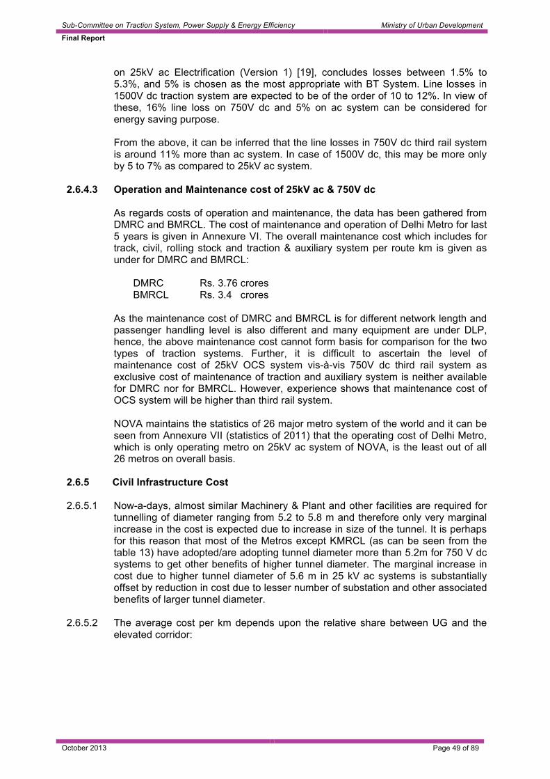
Sub-Committee on Traction System, Power Supply & Energy Efficiency Ministry of Urban Development
Final Report
October 2013 Page 49 of 89
on 25kV ac Electrification (Version 1) [19], concludes losses between 1.5% to 5.3%, and 5% is chosen as the most appropriate with BT System. Line losses in 1500V dc traction system are expected to be of the order of 10 to 12%. In view of these, 16% line loss on 750V dc and 5% on ac system can be considered for energy saving purpose.
From the above, it can be inferred that the line losses in 750V dc third rail system is around 11% more than ac system. In case of 1500V dc, this may be more only by 5 to 7% as compared to 25kV ac system.
2.6.4.3 Operation and Maintenance cost of 25kV ac & 750V dc
As regards costs of operation and maintenance, the data has been gathered from DMRC and BMRCL. The cost of maintenance and operation of Delhi Metro for last 5 years is given in Annexure VI. The overall maintenance cost which includes for track, civil, rolling stock and traction & auxiliary system per route km is given as under for DMRC and BMRCL:
DMRC Rs. 3.76 crores BMRCL Rs. 3.4 crores
As the maintenance cost of DMRC and BMRCL is for different network length and passenger handling level is also different and many equipment are under DLP, hence, the above maintenance cost cannot form basis for comparison for the two types of traction systems. Further, it is difficult to ascertain the level of maintenance cost of 25kV OCS system vis-à-vis 750V dc third rail system as exclusive cost of maintenance of traction and auxiliary system is neither available for DMRC nor for BMRCL. However, experience shows that maintenance cost of OCS system will be higher than third rail system. NOVA maintains the statistics of 26 major metro system of the world and it can be seen from Annexure VII (statistics of 2011) that the operating cost of Delhi Metro, which is only operating metro on 25kV ac system of NOVA, is the least out of all 26 metros on overall basis.
2.6.5 Civil Infrastructure Cost
2.6.5.1 Now-a-days, almost similar Machinery & Plant and other facilities are required for
tunnelling of diameter ranging from 5.2 to 5.8 m and therefore only very marginal increase in the cost is expected due to increase in size of the tunnel. It is perhaps for this reason that most of the Metros except KMRCL (as can be seen from the table 13) have adopted/are adopting tunnel diameter more than 5.2m for 750 V dc systems to get other benefits of higher tunnel diameter. The marginal increase in cost due to higher tunnel diameter of 5.6 m in 25 kV ac systems is substantially offset by reduction in cost due to lesser number of substation and other associated benefits of larger tunnel diameter.
2.6.5.2 The average cost per km depends upon the relative share between UG and the
elevated corridor:

Sub-Committee on Traction System, Power Supply & Energy Efficiency Ministry of Urban Development
Final Report
October 2013 Page 50 of 89
Table 12 Elevated
(km) U/G (km)
Total (km)
Total cost (Crores INR)
Avg. cost per km (Crores INR)
BMRCL 33.5 8.8 42.3 5738 136
CMRL 21.1 24.0 45.1 6722 149
From the above it is evident that the cost per km for underground section is more than the elevated section. However, exclusive cost of underground section of BMRCL and CMRL is not available.
2.6.5.3 Studies indicate that increase in cost due to higher tunnel diameter of 5.6 m in
case of 25 kV is substantially offset by reduction in cost due to lesser number of substation and other associated benefits of larger tunnel diameter. Actual differential in cost will depend upon the soil conditions, land availability in the city and the following: • Dimensions (length, width and height) of the coach • Number coaches in train and length of train • Minimum curvature • Type of evacuation (side or front) • Traction Voltage • OCS or Third Rail • Soil Temperature • Ideally an optimum size can be arrived at by considering the above factors. However, for practical purposes, for Indian conditions, a tunnel diameter for new Metros may be between 5.2 to 5.7 m.
2.6.5.4 The Table 13 below provides the actual data of regarding tunnel size for various metros built / under construction in India:
Table 13
Tunnel Diameter (in m)
Metro Year of Contract
System Voltage
RS Width (m)
Evacuation
Specified
Concentric Finished Dia
Cost of Tunneling per km
DMRC Ph I (BG) VV-KG
2001 25 kV ac 3.2 Front 5.4 5.55 123
DMRC Ph II (SG) UB-Saket
2007 25 kV ac 3.2 Side 5.6 5.6 110-130
DMRC Ph II (SG) CST-N.Place
2007 25 kV ac 2.9 Side 5.6 5.6 110-135
DMRC Ph III (SG) (Line 7 & 8)
2012-13 25 kV ac 3.2m Front 5.6 5.8 120-140
CMRL (SG) UG Ph I
2011 25 kV ac 2.9m Side 5.6 5.8 140
Hyderabad Metro N/A 25 kV ac 2.9m Front Elevated

Sub-Committee on Traction System, Power Supply & Energy Efficiency Ministry of Urban Development
Final Report
October 2013 Page 51 of 89
Tunnel Diameter (in m)
Metro Year of Contract
System Voltage
RS Width (m)
Evacuation
Specified
Concentric Finished Dia
Cost of Tunneling per km
(SG) BMRCL (SG) 2009-10 750 V dc 2.88m Side 5.4 5.6 160 Ahmedabad (BG) Not
Available 1500 V dc third rail
3.6m (pld) Front Planned 5.7-5.8 Not Available
KMRCL (SG) UG-I 2010 750 V dc 2.88m Side 5.4 5.55 150 KMRCL (SG) UG-II 2010 750 V dc 2.88 Side 5.4 5.60 112
2.6.5.5 Other things being same (coach dimensions, evaluation strategy etc.),
theoretically, the adoption of dc third rail traction system (750V or 1500V dc) will require smaller diameter tunnel. However, tunnel diameters adopted in India don’t establish a causal relationship between the traction voltage and tunnel diameters. Experience of many world Metros working with 750 V dc third rail traction system indicate that they have adopted tunnel diameter of around 5.6 m, to derive other benefits of larger tunnel diameter as increase in cost is marginal due to increased earth work and jacketing with the use of modern tunnel boring machines (eg. 5.4 m for dc & 5.55/5.6 m for 25 kV ac). As per experts, tunneling cost as a thumb rule can be taken as proportional to tunnel diameter i.e. variation of about 3 to 4% between 5.4 & 5.6 m.
2.7 Reliability and redundancy measures
DMRC/CMRL and BMRCL, while finalizing the designs and selecting the components have given high weightage to technology that provides maximum reliability and requires minimum maintenance.
2.7.1 Some of the measures of BMRCL are as under: 2.7.1.1 At Receiving Sub Station (RSS) level, there is 100 % redundancy in:
(i) Two independent feeders have been provided from the GSS (s) of the power
supply authority, so that even if one feeder is down for some reason, the other feeder can take care of the Metro loads.
(ii) Two transformers are provided for the traction/auxiliary loads, with one being
as hot standby and have load throw over feature to automatically switch over to the healthy feeder in case of the running feeder becomes defective.
(iii) Two RSSs are there for each corridor, with each RSS normally feeding half the
section but with a Circuit Throw Over feature to switch over to the other RSS in case of one RSS going out of service for some reason.
2.7.1.2 100 % redundancy is provided at the Auxiliary Sub Station (ASS) level in terms of
a standby transformer at ASS. For TSS the redundancy is provided for N-1 condition (i.e. unhindered operations in the event of outage of one TSS).
2.7.1.3 Use of ring main for the auxiliary and traction feeder circuits at 33 kV level to
ensure uninterrupted power supply

Sub-Committee on Traction System, Power Supply & Energy Efficiency Ministry of Urban Development
Final Report
October 2013 Page 52 of 89
2.7.1.4 Use of independent double circuits (with one circuit being standby) for auxiliary
and traction feeders at 33 kV level to ensure uninterrupted power supply in the event of failure of one feeder.
2.7.1.5 Each section of third rail is fed from two Traction Sub Stations, with the provision
for feed extension from the adjacent TSS in the event of failure of one substation 2.7.1.6 The rigid third rail provides a mechanically stable power feeding arrangement
which is able to take the rigours of disturbances on account of contact with the moving rolling stock with less wear and tear
2.7.1.7 Use of dry type transformers in the ASSs 2.7.1.8 Use of microprocessor controlled fast acting relays for clearing of faults 2.7.2 Measures of DMRC/CMRL for uninterrupted power supply 2.7.2.1 At Receiving Sub Station (RSS) level, there is 100% redundancy
(i) Two independent feeders have been provided from the GSS (s) of the power
supply authority, so that even if one feeder is down for some reason, the other feeder can take care of the Metro loads.
(ii) Two transformers are provided for the traction and two for auxiliary main power
supply for using one as hot standby.
2.7.2.2 100 % redundancy is provided at Auxiliary Sub Station (ASS) in terms of a standby transformer.
2.7.2.3 Use of ring main for the auxiliary circuits at 33 kV level to ensure uninterrupted
power supply 2.7.2.4 Use of double circuits (with one circuit being standby) for auxiliary and traction
feeders at 33 kV/25kV level to ensure uninterrupted power supply in the event of failure of one feeder
2.7.2.5 Use of rigid OHE in the underground corridors of 25 kV ac sections provides the
same stability as third rail in the case of 750 V dc and needs less maintenance. 2.7.2.6 Use of GIS at RSS 2.7.2.7 Use of GIS at SP and SSP in thickly populated areas. 2.7.2.8 Use of composite insulators on main line with higher creepage distance of 1050
mm, which are also vandalism proof and do not require frequent cleaning. 2.7.2.9 Problem of bird menace which were initially faced by DMRC, has been addressed
by providing fittings for keeping birds away 2.7.2.10 Use of dry type transformers in the ASSs 2.7.2.11 Use of microprocessor controlled fast acting relays for clearing of faults

Sub-Committee on Traction System, Power Supply & Energy Efficiency Ministry of Urban Development
Final Report
October 2013 Page 53 of 89
2.7.3 NOVA maintains the statistics of 26 world leading metros and it is noted from the statistics of 2011, which is given in Annexure VIII, that number of incidences-wise DMRC is at 5th position and its performance is more or less comparable with other four better metros above it. It is to be noted that incidences includes all cases of rolling stock, power supply, signal, track etc., which affects interruption of train operation for more than 5 minutes. Thus, the overall reliability of Delhi Metro with 25kV ac OCS system can be considered comparable with any other metro of 750V dc third rail system.
2.8 Maintenance needs and philosophy of maintenance of traction system 2.8.1 Maintenance need
The maintenance schedules for DMRC and BMRCL are based on the recommendations of the original equipment manufacturers and evolved over a period of time based on the O&M experience. The schedules need to be continuously monitored and reviewed for their adequacy and their periodicity is based on the O&M field experience. There may be need to eliminate/reduce the frequency of schedules of some items. On the other hand, if the field performance mandates based on experience, some items may require more attention.
2.8.2 Philosophy of maintenance In both the cases i.e. DMRC and BMRCL, the maintenance of the traction and power supply system is done using in-house resources. DMRC follows mixed approach of maintenance with Time based schedules and predictive maintenance. BMRCL maintenance regime consists of Preventive and corrective maintenance.
2.9 Economic Viability for a sample corridor of 25 km length on via duct 2.9.1 As discussed in Para 2.6.1.6.2, the average cost of 25kV ac traction system for
elevated corridor is Rs. 9.32 crore, for underground corridor it is Rs. 11.20 crore and for 750V dc third rail traction system, it is Rs.13.36 crore. Thus, there will be saving of Rs. 4.04 crore per km. i.e. 30% on elevated corridor and Rs. 2.16 crore per km. in the underground corridor if 25kV ac traction system is adopted instead of 750V dc traction system. It may be worth mentioning that the estimated cost for 25kV ac system is for 60000 PHPDT whereas for 750V dc traction system estimated cost is for 48000 PHPDT. However, if the cost of both the traction system is compared for the same level of traffic i.e., 48000, the saving on elevated corridor will be more than 30%, as indicated in ensuing Para 2.9.1.1.
2.9.1.1 An assessment of the cost difference between 750V dc traction system with third rail and 25 kV ac traction systems with OCS has been carried out for different level of traffic for elevated metro. This analysis is related to DPR of Kochi Metro [16] and is given in Annexure IX. Based on this; the results can be summarized as under:

Sub-Committee on Traction System, Power Supply & Energy Efficiency Ministry of Urban Development
Final Report
October 2013 Page 54 of 89
Table 14
PHPDT % reduction in cost with 25 kV ac traction over 750V dc
12000 15 – 20 % 40000 21 – 26 % 50000 27 - 32 %
From the above analysis, it is revealed that in terms of initial cost of construction 25 kV ac system is cheaper on elevated corridor and cost economics further goes in favour of 25 kV ac with the increase of traffic level.
2.9.2 Comparison of energy consumption
Comparative performance of energy consumption of rolling stock on 25kV ac and 750V dc traction system can be best evaluated by using rolling stock with similar performance and under similar operating and climatic conditions. However, existing DMRC and BMRCL stock have different widths, different accelerations and different operating speeds and are working in different climatic conditions. In order to estimate energy saving in 25kV ac system vis-à-vis 750V dc system for a sample corridor, specific energy consumption for the period October-December 2012 of the existing stock of DMRC (RS-2) and BMRCL have been taken into account. DMRC RS-2 rolling stock is 3.2m. wide and it operates at 75kmph with acceleration of 0.82m/sec2. Considering loading of 2000 passengers in 6-car rake @ 68kg. per passenger, the weight of RS-2 stock including weight of additional equipment like transformer and front-end converter is 381.8 tonne and 361 tonne for dc stock of BMRCL. The specific energy consumption of DMRC RS-2 stock is 48kwh/1000 GTKM for the period Oct to Dec 12. 750V dc BMRCL stock is 2.9m. wide and at present operates at maximum speed of 65kmph with acceleration of 1.0m/sec2 and with the present level of operation, its specific energy consumption is 61kwh/1000 GTKM. As given in Annexure X, the energy consumption in 750V dc traction system, while operating at maximum speed of 65kmph and with acceleration of 1.0m/sec2,is 361x50x24x61÷1000 = 26425kwh. Energy consumption for RS2 type of stock of DMRC with maximum operating speed of 75kmph and acceleration of 0.82m/sec2 is 381.8x50x24x48÷1000 = 21992kwh. This brings in saving of 16.5% in 25kV ac system (Ref. Annexure X). It may be noted that this saving takes into account higher weight of rolling stock in 25kV ac system due to additional equipment like transformer and front-end converter and also the level of regeneration which is presently being achieved in DMRC and BMRCL.
2.9.2.1 DMRC has got simulation study done from M/s Bombardier (given in Annexure XI) to
evaluate energy consumption of existing 25kV ac DMRC stock (with 50% motorization) as well as proposed stock (with 67% motorization) and 750V BMRCL stock (with 67% motorization) for round trip of 81.51 km for Line-4 of DMRC. The simulation result indicate that if net energy consumed by existing 25kV stock (with 50% motorization) is 100%, then for proposed ac stock (with 67% motorization), it is 87% and for BMRCL stock (with 67% motorization), it is 127%. Considering the simulation results, it can be seen that there is an energy saving of about 21% in existing 25kV ac rolling stock (50% motorization) as compared to existing BMRCL 750V dc stock and it improves to 31.5% with 67% motorization of ac stock.
2.9.3 Line loss in ac system is around 5% whereas in dc it is 16% as discussed in para
2.6.4.2. Annexure X indicates net energy saving of 7561.5 kwh in one hour during peak period in 25kV ac system, i.e., 25% after taking into consideration line losses

Sub-Committee on Traction System, Power Supply & Energy Efficiency Ministry of Urban Development
Final Report
October 2013 Page 55 of 89
and regeneration in respective traction system. This estimation of 25% of energy saving is for a sample corridor of 25 km to cater to traffic requirement of 48,000 PHPDT with acceleration of 0.82m/sec2 and maximum operating speed of 75 kmph in ac and with acceleration of 1.0m/sec2 and maximum operating speed of 65kmph in dc. It may be noted that 2000 passenger loading has been considered in both the stock for 6-car rake even though ac stock has 14% more capacity.. This compares favourably with RSSB report T-950 which shows saving of 25% for main line operation where regeneration is quite less, with line loss of 21% on 750V dc traction. Energy saving is high in metro system due to higher level of regeneration, especially on 25kV ac system. The saving is expected to be more if stock with similar performance and under similar operating and climatic conditions are used.
2.9.4 Studies indicate that the energy saving in 25 kV ac system may increase to above 35% with the use of higher acceleration of 1.0 m/s2, using 4M+2T rake as compared to existing 750 V dc 4M+2T i.e. both operating with same acceleration and speed.
2.9.5 Metro operation can be considered for 18 hours a day in India with peak loading of 6 hours a day i.e., 3 hours in morning and 3 hours in evening. In non-peak hours, the average traffic can be considered as 50% which can be easily catered even with half frequency of trains. The net daily saving in energy will be 90738 kwh with adoption of 25kV ac traction system as compared to 750V dc traction system while operating existing DMRC stock at 75kmph, with acceleration of 0.82m./sec2 and BMRCL stock at 65kmph, 1.0m/sec2 acceleration & BMRCL. Considering charges of one unit as Rs.5.00, the net daily saving will be Rs.4.54 lakh and annual saving of Rs.16.56 crore. This annual saving will further increase with the upward revision of electricity charges in future.
2.9.6 The sample corridor of 25 km has been taken for elevated metro. There is no
underground section in the sample corridor but in metros where underground section exist, there will be marginal increase in cost due to higher tunnel size which is substantially offset by lesser numbers of substations and other benefits of higher tunnel size as discussed in Para 2.6.5.
2.9.7 There are differing views on the level of regeneration in DC traction system specially
in 750 V dc. The views of M/s Alstom on regeneration are “with AC regeneration is practically always possible, with DC the number of trains in line and the distance between the trains have to be taken into consideration, in generally 30% of regenerated energy is a mean value” as per their email dated 20th March 2013. However M/s Bombardier, as per their simulation report given in annexure-XI & UIC indicate regeneration level in 750 V dc system as 50% where as in 25 kV ac traction system various reports and manufacturers indicate that the regeneration is practically always possible i.e. 100%. Even RDSO’s views are in line with M/s Bombardier and UIC on regeneration in 750 V dc and 25 kV ac.
In view of these, there is a need to take up simulation studies to evaluate energy saving in 25 kV ac vis-a-vis 750 V dc traction system with similar performance and under similar operating & climatic conditions with advance technology 4M+2T rake composition.
2.9.7.1 M/s Alstom in their email dated 20th March 2013 has further indicated efficiency of
25 kV ac Rolling Stock as 86%. Higher efficiency in 25 kV ac Rolling Stock i.e. upto 90% is possible by utilizing more efficient available transformer and traction

Sub-Committee on Traction System, Power Supply & Energy Efficiency Ministry of Urban Development
Final Report
October 2013 Page 56 of 89
convertor as per the details collected by RDSO from manufacturers. It is worth mentioning that in the report for efficiency and regeneration of rolling stock, internationally accepted criteria i.e., specific energy consumption has been considered.
2.9.8 Summary
Following inferences can be drawn from above for sample corridor of 25 km elevated metro.
2.9.8.1 750V dc traction system on elevated corridor of sample corridor of 25 km, catering
to traffic need of 48000 PHPDT will be 30% more costly than 25kV ac traction system. It has been further observed that the cost difference increases with the increase of traffic requirement.
2.9.8.2 Rolling stock for 25kV ac traction is generally expected to be costlier for similar dc
link voltage compared to cost of rolling stock for 750V dc traction on account of additional equipment like front end converter and transformer. However, there is an inherent advantage in 25kV ac system that it can adopt higher dc link voltage like 1800V, which helps in reducing the size and cost of converter / inverter, transformer and traction motor. The experience of various metros of India shows that the cost of rolling stock of 4M+2T combination of 25kV ac and 750V dc is comparable.
2.9.8.3 Although the weight of 25kV ac rolling stock is more as compared to 750 V dc
stock, yet there is energy saving of 25% while operating 25 kVac stock at 75 kmph and 750 V dc stock at 65 kmph using existing DMRC stock (with 50% motorization), BMRCL stock (66% motorization) due to higher level of regenerated energy, low line losses in ac system. However, the energy saving is expected to increase further if ac stock under procurement (with 67% motorization) is used.
2.9.8.4 Operation and maintenance cost
(i) Maintenance cost of 25kV ac traction is expected to be more than 750 V dc
with third rail. Sufficient experience is not available to assess the maintenance cost of third rail system, since the third rail system in BMRCL is newly installed. However, a comparison has been done by NOVA of 26 Metros based on the statistics furnished by various Metros for 2011. This indicates that over all O&M cost achieved in Delhi Metro, (25kV ac traction system) is lowest.
(ii) Life of composite third rail is expected to be higher than the life of flexible OCS
for the same traffic level. (iii) Third rail 750 V dc/1500 V dc and rigid OCS for 750/1500 V dc is expected to
give nearly same life. (iv) Rigid OCS for 25 kV ac is expected to have a longer life as compared to
750/1500 V dc because of lower currents being collected with lower pressure and softer material of current collector.
(v) Overall cost of maintenance of a traction system will depend upon the mix of
underground and elevated section.

Sub-Committee on Traction System, Power Supply & Energy Efficiency Ministry of Urban Development
Final Report
October 2013 Page 57 of 89
2.10 Upcoming technologies 2.10.1 Technologies to retrieve regenerated energy in dc traction system
Modern rail metro utilizes three phase propulsion equipment where recovery of energy while braking is possible. The train generates energy during electric braking process and during peak period, the re-generated energy is utilized by nearby trains. While in ac network, optimum recovery of re-generated energy is possible if the traffic density is high due to longer feeding section and higher voltage, but it is not always possible to retrieve optimum re-generated energy in dc traction system. Ticket to KYOTO – “An Overview of braking energy recovery technologies in the public transport field – March 2011” [22] has addressed in detail issues regarding recovery in dc traction systems. It has defined three types of applications for recovery of regenerated energy: • Mobile Storage Application, • Stationary Storage Application and • Stationary back to the grid application It has stated further that to avoid energy losses and to reduce the overall energy consumption, solutions are being developed by various suppliers. In order to ensure optimum utilization of re-generated energy in dc traction system, based on study of available literatures and input from industries following stationary measures are under development at traction substation level by different countries:
2.10.1.1 Provision of either of the following energy storage system at traction substation
• Flywheel arrangement – RATP RER Paris has a successful experience of
using flywheel as a energy storage device and this also acts as a voltage stabilizer. This is installed at Fort Aubervilliers station of line 7.
• Super Capacitor – This has been tried out by Toronto TTC. • Powerful Batteries Further reference can be made to ‘Efficient recovery of braking energy’ [23]. These energy storing devices also help in voltage stabilization, peak demand saving, energy assurance in the case of a power outage and potential reduction in maintenance cost. These are still under development although some metros have started installing on experiment basis as is given to understand by the manufacturers viz., M/s. Alstom and Bombardier.
2.10.1.2 Provisions of inverter at substation to recover re-generated energy and allow
feedback energy to the Grid or 11/22/33kV auxiliary network: During non-peak period, especially when the trains are few and also when the line becomes non-receptive, inverters installed at substation help to recover the energy by channelling them back to auxiliary power supply network. Bilbao metro, Spain and Singapore Metro at some stations and Guangzhou Metro, on one of their 1500V dc traction line, have used inverter for recouping re-generated energy. Brussels STIB, London underground have also used it on trial basis. Experiences of all these metros are positive about it.

Sub-Committee on Traction System, Power Supply & Energy Efficiency Ministry of Urban Development
Final Report
October 2013 Page 58 of 89
2.10.2 1500V dc third rail traction system
Chinese metros, particularly Guangzhou and Shenzhen have adopted 1500V dc third rail system on their few lines, which has been developed by Chinese Industry with association with European Industry. So far, 117 km. network length is operating on 1500 dc third rail system. Committee members visited Guangzhou Metro to study the experience and design aspects of 1500V dc third rail traction system and also to have interaction with their industries. It is noted during visit that Guangzhou Metro has adopted 1500V dc third rail system on aesthetic and reliability considerations on lines 4 and 5 over network length of 75.6 km., which has underground as well as elevated sections near coastal area, prone to thunder storm and lightening for few months in a year. Line 6, Phase 1 under construction is also coming up with third rail for a network length of 24.3 km. Part of Line 4 started operation in 2005 but major portion of Line 4 & 5 came in operation after 2008. It was reported that there has not been any major problem in 1500V dc third rail system. Its major constraints were reported to be requirement of power block for any kind of attention to track, signalling and other equipment and side evacuation. They are adopting 1500V dc rigid OCS on all new lines viz. lines-7, 9, 13, 14 etc., mostly underground, on account of operational reasons.
2.10.3 2x25kV ac traction system
Seoul Metro, South Korea has adopted 2x25kV ac traction system on their Sin Bundang high speed metro line. It is to be noted that this traction system has inherent advantage of low line loss of the order of 1.5%, higher inter substation spacing, less EMI/EMC problems and can easily meet high power density requirement in a congested city. The system, however, needs to be studied further for adopting on Indian Metro.
2.11 Conclusion and the way forward
2.11.1 Based on detailed study of various traction systems adopted world over, the study
on technical feasibility of traction systems for various levels of traffic and technological development, following position emerges:
Table 15
Type of MRTS
PHPDT Traction Voltage Feasible
Cap Cost*
Energy re-generation
Remark
750 V dc third rail
(a) 125% (a) 18-20%
1500 V dc OCS
(b) 115% (b) 20-22%
LRT 15000 to 30000
25 kV ac OCS
(c) 100 (c) >35%
(a) 750 V dc third rail
(a) 135% (a) 18-20%
(b) 1500 V dc OCS
(b) 115%
(b) 20-22%
Medium 30000 to 45000
(c) 25 kV ac OCS (c) 100 (c) >35%
(a) 1500 V dc (a) 120% (a) 20-22% Heavy MRTS
> 45000 <75000 (b) 25 kV ac (b) 100 (b) >35%
(a) 750 V dc third rail does not have overhead conductor system. It looks good from aesthetic point of view on elevated section. (b) & (c) In U/G OCS does not affect

Sub-Committee on Traction System, Power Supply & Energy Efficiency Ministry of Urban Development
Final Report
October 2013 Page 59 of 89
Type of MRTS
PHPDT Traction Voltage Feasible
Cap Cost*
Energy re-generation
Remark
aesthetics 2X25kV ac May be adopted in busy congested
area of city where there are limitations of getting supply at 66kV/22kV and has lesser EMC/EMI problems
*The capital cost pertains to electrification system cost only and it does not capture the impact on rolling stock and civil infrastructure costs due to traction system Note: 1. PHPDT on 750 V dc is validated by subgroup on theoretical study (Annex V). 2. Issue of aesthetics, however, is a tenuous one in decision-making matrix.
While taking decision based on aesthetics, it should be considered that there is widespread acceptance of OCS even in tourism centric countries like Switzerland and industrialized nations like Japan.
2.11.2 Energy scenario in different traction system 2.11.2.1 Actual records of DMRC (BG Lines - 120 km) & BMRCL (7 Km) reveal an energy
saving of 25% in 25 kV ac traction system operating with acceleration of 0.82 m/sec2 and maximum speed of 75 kmph versus 750 V dc traction system in BMRCL operating at a higher acceleration of 1.0 m/sec2 but at lower maximum speed of 65 kmph.
2.11.2.2 The energy saving in 25 kV ac system may be more than 35% with the use of
higher acceleration of 1.0 m/sec2 (with 4M+2T rake under procurement with imported technology now available) as compared to existing 750 V dc 4M+2T i.e. both operating with an acceleration of 1.0 m/sec2 and maximum speed of 75 kmph.
2.11.2.3 With the increasing cost of electric energy & in an effort to optimize traction
energy, now metros working on 750V dc /1500V dc are exploring methods to improve recuperation of regenerated energy upto 32% even with additional expenditure by using additional technology like inverter, storage devices at sub-stations which are under development and trial in different countries. The cost of these additional technologies is quite substantial as of now, but is expected to reduce with the passage of time, deployment of modern electronics & software.
2.11.3 Impact on tunnel diameter
Other things being same (coach dimensions, evaluation strategy etc.), theoretically, the adoption of dc third rail traction system (750V or 1500V dc) will require smaller diameter tunnel. However, tunnel diameters adopted in India don’t establish a causal relationship between the traction voltage and tunnel diameters. Experience of many world Metros working with 750 V dc third rail traction system indicate that they have adopted tunnel diameter of around 5.6 m, to derive other benefits of larger tunnel diameter as increase in cost is marginal due to increased earth work and jacketing with the use of modern tunnel boring machines (eg. 5.4 m for dc & 5.55/5.6 m for 25 kV ac). As per experts, tunneling cost as a thumb rule can be taken as proportional to tunnel diameter i.e. variation of about 3 to 4% between 5.4 & 5.6 m. .

Sub-Committee on Traction System, Power Supply & Energy Efficiency Ministry of Urban Development
Final Report
October 2013 Page 60 of 89
2.11.4 Cost of rolling stock
The existing experience of different Indian Metros shows that the cost of 25kV ac rolling stock is comparable with 750V dc rolling stock, perhaps, due to inherent advantage in 25kV ac system of adopting higher dc link voltage and its large volume of requirement even though it utilizes additional equipment like transformer and front end converter.
2.11.5 Summary 2.11.5.1 25kV ac is most economical followed by 1500V dc compared to 750V dc traction
system both from initial cost (of direct electrification system) point of view as well as energy efficiency. But from aesthetic point of view, 750V/1500V dc third rail is better as it does not have overhead conductor system (OCS). Regeneration of energy has been feasible in modern rolling stock because of development of VVVF drive in 1990s & old metro Rolling Stock does not have this feature.
2.11.5.2 1500V dc third rail has recently been adopted by Guangzhou and Shenzhen
Metros in China on few lines. This has been developed by Chinese Industry recently in association with European industry. The Committee visited Guangzhou Metro to study experience and design aspect of 1500V dc third rail system. Summary of visit is given in Para 2.2.3.2. Guangzhou Authority has confirmed that there has been no major problem with 1500V dc traction system. Its major constraints were reported to be requirement of power block for any kind of attention to track, signalling and other equipment. Guangzhou Metro is now adopting 1500V dc rigid OCS on all future lines except Line-6, on operational reasons.
Guangzhou Metro has installed inverter at substation, on trial basis, on one line for capturing regenerated energy. It is reported that regeneration on this line is 30% even in non-peak hours.
2.11.5.3 Out of 184 transit systems worldwide having 573 lines and 9394 stations with a
combined length of 10641 km, around 75% network utilizes third rail system. Over 12 heavy metros have overhead 1500 V dc system. Recently heavy metros like Seoul, Delhi, Hyderabad and Chennai have adopted 25 kV ac system. Bangalore Metro with projected traffic level upto 40,000 phpdt has adopted 750 V dc system.
2.11.5.4 For modern 750 V dc traction system some of the major systems like low loss
composite aluminium third rail, oil-less (dry type) transformer rectifier set, dc switchgear, high speed circuit breaker, bus duct etc. are not available indigenously.
2.11.5.5 Modern 25 kV ac systems, adopted by Delhi Metro, has a few fittings superior and
different than and superior to Indian Railways. Some of the sub-systems like light weight section insulators, typical potential transformer and current transformer, neutral section arrangement, 25 kV gas insulated sub-station, rigid overhead system, synthetic insulators etc. are imported.
2.11.5.6 Simulation programmes are essential to determine and predict requirement of
traction load, for various headways of trains, study of EMC/ EMI effect, sizing of equipment etc. There is need for development of simulation package in India with the help of institutes like DTU, IIT & industry.

Sub-Committee on Traction System, Power Supply & Energy Efficiency Ministry of Urban Development
Final Report
October 2013 Page 61 of 89
2.11.5.7 The way forward
Metros in India may consider adoption of 25 kV ac or 1500V dc or 750V dc presently. The objective and considerations for selection of 750V or 1500V dc or 25 kV ac should keep in view route of a particular rapid transit line in the city, elevated or underground, above knowledge of technical feasible systems, their capabilities, economic viability based on capital cost and operational cost, platform screen doors, aesthetics and environmental conditions peculiar to the area of the city. Seoul Metro on their high speed Sin Bundang Line have recently adopted more energy efficient 2x25kV system, and needs further detailed study. Based on above study, though it may be desirable to go for a nominal voltage of 825V dc for third rail, which have been adopted by 13.4% metros i.e., USSR, China and European countries, to reduce line losses and improve regeneration, but this would require development for Indian conditions and may need to be considered on techno-economic consideration.

Sub-Committee on Traction System, Power Supply & Energy Efficiency Ministry of Urban Development
Final Report
October 2013 Page 62 of 89
3.0 INTERNAL POWER DISTRIBUTION SYSTEM Report of analysis and recommendations for standardization of internal power distribution system
3.1 Internal Distribution System Metro systems have their own internal HV cable distribution network – generally at 11kV or 22kV or 33kV. The purpose of such cable distribution network is to feed all auxiliary substations at each station as well as feed traction substations in case of dc traction system. Following distribution network has been adopted by different Indian Metros:
Table 16 Kolkata Metro (Indian Railways)
11kV internal cable distribution system
DMRC
33kV internal cable distribution system
BMRCL
33kV internal cable distribution system
CMRL, JMRC
33kV internal cable distribution system
MMRC, Mumbai 11 kV internal cable distribution system for Metro 22 kV internal cable distribution system for Monorail
On overseas Metros, it has been observed that majority of the Metros have gone for a 33 kV auxiliary distribution system (China, Dubai, Brazil, Bangkok). UK has gone for 22 kV system on London Metro. On some of the lines of the London Metro, 11 kV has also been used. In Korea 22 kV network has been used. Australia has adopted 11 kV network. Reference can be made to [24-27]
3.2 Technical Feasibility
3.2.1 In view of reliability, both ac and dc traction system have adopted cable distribution system in redundant configuration i.e. failure of one cable network does not impair any ASS or TSS functionality and other cable network ensures providing power supply.
This is an established practice around the world and shall continue.
3.2.2 In case of 25 kV ac traction systems, the traction and auxiliary networks get
separated at 25 and 33 kV voltage level and as such the issue of separation of auxiliary & traction networks through internal distribution system is not relevant for such systems.
3.2.3 However, in case of DC traction system, the same type of cable distribution
system feeds the traction substations, therefore the issue of ‘separate’ or ‘common’ 33kV networks become an issue of deliberation.

Sub-Committee on Traction System, Power Supply & Energy Efficiency Ministry of Urban Development
Final Report
October 2013 Page 63 of 89
3.2.4 Currently, practices adopted by Indian and some overseas metro are as under:
Table 17 BMRCL Four 33kV cable circuits, two for auxiliary and two traction
networks. The point of common coupling (PCC) is at 33kV busbar of receiving substations (RSSs).
Kolkata Metro (IR)
Common 11kV cable circuits in redundant configuration i.e. two cable system. The PCC is at station (TSS) level. Kolkata Metro has a 33kV ring main network also which feeds 33kV/11kV RSS.
Bangkok BTS / MRTA
Four 24kV cable circuits, two for auxiliary and two traction networks. The point of common coupling (PCC) is at 24kV busbar of receiving substations (RSSs).
Washington Metro
Common 13.8kV cable circuits in redundant configuration i.e. two cable system. The PCC is at station (TSS) level.
Singapore Metro Common 22kV cable circuits in redundant configuration i.e. two cable system. The PCC is at station (TSS) level.
KMRCL Four 33kV cable circuits, set of two circuits for half of substations with common auxiliary and traction networks. The PCC is at station (TSS) level.
Guangzhou Metro
Common 33 kV cable circuits in redundant configuration i.e. two cable system. The PCC is at station (TSS) level.
3.2.5 When DMRC planned underground line of Vishwa Vidyalaya to Central
Secretariat initially with 1500V dc traction system, full designs were developed by adopting common cable circuits for traction and auxiliary networks.
3.2.6 Discussion on various options of distribution network
3.2.6.1 There are several possible configuration for internal distribution network e.g.
during design of BMRCL power supply system, following options were deliberated: (i) Two cable system with common busbar for ASS and TSS (ii) Two cable system with separate busbar for ASS and TSS (in normal
scenario and possibility of feed extension in case of failure) (iii) Three cable system with one cable for each ASS and TSS and third
common redundant cable to be used in the event of failure of ASS or TSS supply cable
(iv) Four cable system, each TSS and ASS have two separate feeder cables
3.2.6.2 The figures 1 to 5 provide the schematic arrangement [24-27] of various options deliberated above. Depending on the objective and budget, redundancies can be built or removed. For example, even two cable system can provide full separation of auxiliary and traction networks in the normal scenario, but in case of fault, separation would not be possible. Further, 2 cable system can ensure full separation and redundancy even in case of outage scenario if the feeds are from the two ends.
3.2.6.3 It can, therefore, be concluded that selection of a particular type of distribution network is dependent on:
(i) Whether separation of auxiliary and traction networks is foreseen (ii) Whether such separation is foreseen for normal scenario only or also for
outage scenario

Sub-Committee on Traction System, Power Supply & Energy Efficiency Ministry of Urban Development
Final Report
October 2013 Page 64 of 89
(iii) Whether feeds are from both the ends or in somewhere in the middle. (iv) Redundancies planned in the system (v) Reliability of the system (vi) Power quality issues for auxiliary load (vii) Most importantly, budget availability
3.3 Pros and cons of different distribution networks
3.3.1 Four Cable scheme
3.3.1.1 This scheme provides higher reliability and has flexibility of feeding traction and
auxiliary power separately without, in any situation, mixing the two supplies. The fault identification and reconfiguration can be implemented very fast through remote control and does not involve sophisticated procedure and avoid confusion. Further, both the transformers of both ASS and TSS will be fed from separate cables and not through common bus. However it will be possible to extend supply from one transformer (both ASS and TSS) to other half (in TSS through the bus coupler downstream of 33kV busbar for TSS and on LT side in case of ASS).
3.3.1.2 Since traction and auxiliary power supplies are completely segregated in all situations, protection setting can be systematically introduced and achieve high selectivity in any fault scenarios.
3.3.1.3 Two ASSs in underground stations can be easily implemented with this scheme, though on the LT side, tie bus and cables will be required for this purpose.
3.3.1.4 The size of 33kV cables can be decided to carry either only auxiliary load or only traction load.
3.3.1.5 It is possible to use ring main units (RMUs) which will save space and cost.
3.3.2 Three Cable Scheme
3.3.2.1 In three cable system, though the feed to traction and auxiliary circuits are segregated in normal operation mode, but both the transformers of ASSs and TSSs at one station are fed from one supply. Therefore in case of failure of feed or the busbar fault, the entire power will have to be switched off for certain time.
3.3.2.2 Although in case of supply failure of either traction or auxiliary it will be possible to provide feed through the third cable; however that would involve complex operational design for switchgear operations. Further the system restoration will be cumbersome at the time of fault identification and rectification.
3.3.2.3 Third (floating) cable will be used for feeding auxiliary or traction power depending upon situations. The protection settings of auxiliary and traction system will be different. Therefore, it shall be difficult to achieve protection setting and relay coordination for the feeder breakers of the third cable.
3.3.2.4 All the 3 cables will have to be sized to higher of the full traction or auxiliary power requirement.
3.3.2.5 The underground stations are provided with two ASSs each with one transformer, while this scheme provides one ASS with two transformers. Though theoretically this scheme can be implemented by sectionalizing the ASS side 33kV busbar through a bus coupler and connecting the two ASSs through 33kV cables, but this

Sub-Committee on Traction System, Power Supply & Energy Efficiency Ministry of Urban Development
Final Report
October 2013 Page 65 of 89
is not considered efficient scheme and also the operational planning is cumbersome.
3.3.2.6 This scheme will require additional 3 (stations with only ASS) and 4 (stations with TSS and ASS) 33kV switches to create redundancy and interlocking. The saving of one cable will be much less than the additional cost of 33kV switches.
3.3.3 Two cable scheme with separation of Auxiliary & Traction networks
3.3.3.1 This scheme uses two cables – one entirely for traction feed and another for auxiliary power feed in normal operation scenario. There is flexibility of extending 33kV feed from traction circuit to auxiliary circuit at TSS/ASS level 33kV busbar. So in normal operation scenario the protection setting is not a problem, but in case of feed extension scenario (across the circuits), there will be problems and will result in cumbersome operation scheme.
3.3.3.2 Both the transformers of ASSs and TSSs are fed from same busbar without bus sectioning. Busbar faults will lead to complete power shut down, which is not a desirable scenario.
3.3.3.3 The underground stations will be provided with two ASSs each with one transformer, while this scheme shows one ASS with two transformers. Though theoretically this scheme can be implemented by sectionalizing the ASS side 33kV busbar through a bus coupler and connecting the two ASSs through 33kV cables, however, its implementation needs detailed study.
3.3.3.4 Both the cables will have to be sized for full traction plus auxiliary loads.
3.4 Cost Economics
3.4.1 For academic interest, a tentative cost estimation for four schemes has been worked out for 42km network of BMRCL project with the following assumptions: (i) All the equipment upstream of transformers have been factored in the
comparison (ii) 33kV cables assumed to be single core 240 mm2 for 4-cable scheme and
singe core 300 mm2 for other schemes (iii) Two ASSs considered in underground (iv) 1250 Amp Circuit breakers and interrupters in all schemes (v) The incoming breakers from RSS and interconnection breakers to other
line are not considered as these are common in all schemes and will not have any impact.
3.4.2 The results of analysis are given in the following table (cost figures are for
switchgear, protection scheme and cabling):
Table 18 SN Scheme Cost estimates 1 Two cable scheme (common circuits) Rs 81 crore 2 Four cable scheme (separated circuits) Rs 115 crore 3 Three cable scheme Rs 127 crore 4 Two cable scheme (separated circuits in normal case) Rs 87 crore

Sub-Committee on Traction System, Power Supply & Energy Efficiency Ministry of Urban Development
Final Report
October 2013 Page 66 of 89
3.4.3 It is to mention here that the present practice is purely based on the adequacy of technical solution and not on the costs. It is noted that Guangzhou has adopted the two-cable scheme, which needs to be evaluated further before adoption in Indian Metros.
3.5 Recommendations
3.5.1 As far as voltage for the auxiliary systems is concerned, it is preferred that 33 kV be used since the line losses will be lower than losses for 22 kV/11 kV systems and the equipment/switchgear for 33 kV has been already developed and is use on all the new Metros in India.
3.5.2 As far as the number of circuits is concerned, the choice essentially boils down to
reliability versus cost. In normal scenario any of the discussed scheme will work, which makes the two-cable scheme with common circuits also an option which needs further detailed study.
3.5.3 Purely on technical and reliability grounds, separate as well as redundant circuits
for auxiliary and traction networks will be perfect choice. 3.5.4 With technological advancement in the areas of protection system, addition of bus
sectioning, pilot wire protection for cable sections, and improvement in reliability of equipment, common cable circuits for auxiliary and traction networks will offer reliability as well as meet desired performance requirement at reduced cost. Two cable scheme as common circuit can be considered after detailed study in view of the cost advantage.
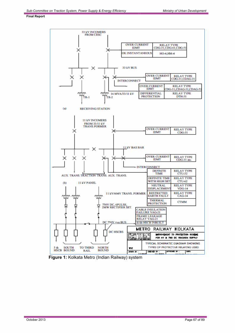
Sub-Committee on Traction System, Power Supply & Energy Efficiency Ministry of Urban Development
Final Report
October 2013 Page 67 of 89
Figure 1: Kolkata Metro (Indian Railway) system

Figure 2: Three cable scheme with segregation of auxiliary and traction networks

Sub-Committee on Traction System, Power Supply & Energy Efficiency Ministry of Urban Development
Final Report
October 2013 Page 69 of 89
Figure 3: Two cable scheme with segregation of auxiliary and traction networks

Sub-Committee on Traction System, Power Supply & Energy Efficiency Ministry of Urban Development
Final Report
October 2013 Page 70 of 89
Figure 4: Four cable scheme with segregation of auxiliary and traction networks (BMRCL)

Sub-Committee on Traction System, Power Supply & Energy Efficiency Ministry of Urban Development
Final Report
October 2013 Page 71 of 89
Figure 5: Two cable scheme with common auxiliary and traction networks

Sub-Committee on Traction System, Power Supply & Energy Efficiency Ministry of Urban Development
Final Report
October 2013 Page 72 of 89
4.0 Indigenization Identifying constraints in the process of indigenous development and evolving strategies for placing developmental orders for imported assemblies, systems and subsystems
4.1 Currently Imported Items In the Metro Scenario today, as far as traction is concerned, following are the major items being sourced from overseas vendors:
4.1.1 750 V dc system (i) Third rail along with accessories like insulated joint, expansion joint and
mounting insulator for third rail. (ii) Third rail fixing brackets (iii) Dry type cast resin transformers for Traction and Auxiliary sub-stations (iv) 220/ 132/ 110/ 66/ 33/ 25 kV Current/ Potential Transformers (v) Rectifiers of traction substations (vi) High Speed Circuit breakers and other DC switchgear items like Short
Circuit Device, Negative Return Panel, By pass panel (vii) SCMS (Stray Current Monitoring System) (viii) Bus ducts for LV connections between transformers and switchgear on the
LV side, bus duct between transformer secondary on the LV side and the rectifier
4.1.2 25 kV ac system
Light weight section insulators, short neutral section, certain OHE fittings, rigid OCS, GIS, dry type cast resin, auxiliary transformers, potential and current transformers etc.
4.1.3 Simulation Packages
All simulation packages used for 750 V dc, 25 kV ac traction power supply systems are imported. In DMRC simulation package of M/s SYSTRA France, M/s Cobra Spain, M/s Ardanuy Spain have been used. In case of design and build contract of CMRL, M/s Siemens have used their own software while in case of BMRCL software of M/s ELBAS Germany has been used.
4.2 Indigenization Approach
4.2.1 High reliability and zero/low maintenance are the basic requirements of any traction system/sub-system/assemblies and would be the key consideration of indigenization, besides cost reduction.
4.2.2 The routes which can be adopted for indigenization are:
(i) Indigenous Technology Development and manufacturing (ii) Transfer of Technology and manufacturing in country
4.3 Constraints in indigenization
Following constraints are there in indigenization:

Sub-Committee on Traction System, Power Supply & Energy Efficiency Ministry of Urban Development
Final Report
October 2013 Page 73 of 89
(i) Local Industries do not have know-how of design control, manufacture and quality assurance for critical costly items like third rail and its associated accessories, DC switchgear items like HSCBs, SCDs etc.
(ii) The volumes may not attract the local industry/global players to set up a manufacturing base in India since the infrastructure required for manufacture and testing would require heavy investments.
(iii) IPR issues with the OEM would be involved for the local vendor.
4.4 Strategy of indigenization
4.4.1 Common enabling specifications of systems/sub-systems for all metros can increase volume of requirement and encourage Indian industries having facilities for manufacturing similar items for Indian Railways for indigenization of these items. Some items can be entrusted for indigenization through industries by overseas firms/ units. However, to ensure technology up-gradation, investments by Indian industries, it is necessary to establish mechanism for assured market. Further, use of indigenously available alternative technologies consistent with requirements can also be explored.
4.4.2 There is need for tie up with Engineering Colleges/ DTU/ IIT for development of
simulation packages. 4.4.3 The OEM should be preferably associated in the indigenization process in case
the onus of indigenization is taken by the Metro Rail authorities and inputs like infrastructure requirement for manufacture and quality assurance shall have to be obtained from the OEM to ensure quality and reliability.
4.4.4 Essential pre-qualification requirements to be met by the agency identified for indigenous manufacture:
(i) Should have the required manpower expertise and skills, infrastructure for
manufacture, testing and quality assurance for the system/sub-system/component
(ii) Should have a pre-defined financial standing (iii) Should have been in the business of design, manufacture, supply, testing,
commissioning and servicing similar products possessing ISO or equivalent certifications.
4.4.5 Items for indigenization of 750V dc and 25kV ac on immediate basis
4.4.5.1 Items in 750 V third rail traction, which can be considered for indigenization on an
immediate basis: (i) Third rail accessories like insulators and fixing brackets
(ii) Shroud for third rail
(iii) Dry type cast resin transformers of all ratings
(iv) Traction transformer and rectifier

Sub-Committee on Traction System, Power Supply & Energy Efficiency Ministry of Urban Development
Final Report
October 2013 Page 74 of 89
4.4.5.2 Items for indigenization of 25 kV ac equipment (i) Light weight section insulator
(ii) Rigid OHE
(iii) Potential/ current transformer
(iv) Dry type auxiliary transformer
(v) Gas insulated sub-stations (GIS)
(vi) Certain imported OHE fittings

Sub-Committee on Traction System, Power Supply & Energy Efficiency Ministry of Urban Development
Final Report
October 2013 Page 75 of 89
5.0 ENERGY EFFICIENCY The energy cost forms single largest expenditure contributor (approximately 25 to 30%) to the total operating cost. As far as commercial/operational viability of any metro is concerned, the energy consumption should be reduced to the barest minimum. In addition, energy is a scarce resource in India and is given to metros/railways on priority basis compared to other lifeline sectors like agriculture and industry; hence metros/railways have the additional responsibility of using it efficiently and judiciously. As the energy operating cost of most of the electrical equipment is substantial component of the total life cycle cost, energy efficiency factor needs to be addressed right from conceptual and design stage itself. In metro, energy consumption consists of following:
• Energy consumption for traction
• Energy consumption for auxiliary services
• Losses in transmission, distribution and transformation Some of the initiatives and factors which can improve the energy efficiency of metros are summarized in figure below as a bird’s eye view. This collection of factors is not comprehensive but it demonstrates that energy efficiency can be improved in a multitude of ways. Some initiatives may yield only small savings, but the sum of these may add up, over time, to a significant reduction in energy consumption. Reducing energy consumption in metro system – a bird’s eye view

Sub-Committee on Traction System, Power Supply & Energy Efficiency Ministry of Urban Development
Final Report
October 2013 Page 76 of 89
Energy efficiency measures for traction and auxiliary system are discussed in the following paragraphs
5.1 Energy Saving Measures in Traction [20-23] Traction system consumes nearly 50% of total consumption. The following methods are widely used for energy efficiency:
5.1.1 Optimum utilization of regenerated braking energy
It has been discussed in Para 2.6.4.1 that retrieval of regenerated energy in 25kV ac system is 100% whereas in dc traction system, it is not possible to utilize this energy fully without adopting additional technology like inverters and energy storage devices. Measures to improve recuperation of regenerated energy in dc traction system has been discussed in Para 2.10.
5.1.2 Maintaining Unity Power Factor
Maintaining unity or near unity power factor contributes towards energy efficiency. 5.1.3 Selection of higher traction voltage system
The transmission efficiency of 25 kV ac traction system is higher compared to dc system because of the fact that the resistive losses are proportion to the square of the current. According to energy road map for the European Railway Sector, dc electrification line losses vary between 15 to 20% whereas ac electrification line losses vary between 3 to 5%. In fact, Seoul Metro, on their high speed Sin Bundang line, have adopted 2x25kV ac traction system where line losses are 1.5 to 2% only [16, 17].
5.1.4 Use of Advance Technology With the development of technology in the field of electronics and material science, metro coaches needs to adopt following energy efficiency measures: (i) Reduction in tare weight of coach through use of lightweight material like
aluminum, FRP, stainless steel (ii) Higher passenger carrying capacity of coach by adopting widest possible
stock and, (iii) Use of energy efficient propulsion equipment
5.1.5 Operational Strategies Adopting operational strategies like coasting, advanced signaling philosophy, ATO, optimized off-peak speeds, minimizing delays, advanced energy management system etc.
5.2 Auxiliary system energy efficiency In Metros, auxiliary system consumes nearly 50% of the total energy. However it may vary from metro to metro depending upon the length of the underground portion where consumption of energy is higher. The metros in Asian countries

Sub-Committee on Traction System, Power Supply & Energy Efficiency Ministry of Urban Development
Final Report
October 2013 Page 77 of 89
consume more power than western countries due to adverse climatic conditions, especially in summer. Reference can be made to [18, 28].
5.3 Latest Trends
5.3.1 Study of latest trends regarding energy efficiency measures and comfort All energy measures have to be such that they do not affect comfort level of the occupants. Every 1 kw electrical power saving reduces emission of about 0.5 ton of CO2 into atmosphere per year.
5.3.2 Use of energy efficient motors for all E&M applications Approximately 75 to 80% of the total auxiliary power is consumed by the equipment operated with motors. So use of energy efficient motors is specially suited for metros to make the system energy efficient. These motors have higher efficiency than ordinary motors and also have better efficiency on partial loads i.e., the efficiency of EEM (Energy Efficient Motor) is almost constant and maximum between 50 to 100% load. Though costlier, the payback period is estimated to be 6 months to one year.
5.3.3 Air conditioning/Environment Control System/TVS Air-conditioning is the single largest consumer of power. In Delhi metro (line 2) each typical underground station is provided with air conditioning of approx 1000 TR (tons of refrigeration) capacity. Total capacity at 10 stations is 10,395 TR of air conditioning. The estimated energy consumption for 16 hours working cycle/day for these plants is 4,00,00,000 kWhr/annum. This consumption would have been higher if air-cooled reciprocating compressor are used instead of water cooled compressor. So sufficient care should be taken during design stage itself and in the selection of equipment. The following measures are suggested: (i) Use of higher COP air-conditioners, higher efficiency filters, insulation of
chilled water pipes/air ducts.
The specific power consumption (KW/TR) of various type of compressors is given below:
Reciprocating Centrifugal Screw Sp. Power consumption (KW/TR)
0.7 – 0.9 0.63 0.65
Screw type compressor is considered best suited for metro applications due to their better performance under partial load operation as the AC plants, like most of the other electrical equipment operate between 50% to 75% of its capacity most of the time
(ii) 1% design criteria to avoid over sizing and unnecessary over operation of
equipments. Over sized equipments operate at lower efficiencies at normal working loads.

Sub-Committee on Traction System, Power Supply & Energy Efficiency Ministry of Urban Development
Final Report
October 2013 Page 78 of 89
(iii) Adopting other design criteria like
• Choice of acceptable conditions inside coaches and station areas using Relative Warmth Index
• Influence of sub soil temperature (iv) Use of energy efficient VRV technology (v) Temperature control sensors (vi) Less or no fresh air for equipment rooms (vii) Provision of Platform Screen Doors (PSD) (viii) Use of water cooled compressors (35 % more efficient than air cooled) (ix) Optimum duty cycle control (modulation) of compressor (x) Free cooling of air-conditioning area during winter (xi) Sensor to operate the fan only when required (xii) Selection of Energy Efficient VAC Equipment (xiii) Pre-cooling of underground tunnels (xiv) Ensuring heat generating electrical equipment (like UPS, battery, battery
charger, stabilizers, heaters, refrigerators etc.) outside the air-conditioned space. There is always an argument that some of these equipment performs better if kept in air-conditioned area, but these equipment are designed to work at the atmospheric or higher ambient temperature.
(xv) To conserve energy spent on air-conditioning following measures can be
taken:
• Motorized blind control. • Zone based cooling control using VAV, thermal diffuser systems.
5.3.4 Energy Efficient Lifts & Escalators
Lifts and Escalator, though the motor rating is medium, because of their huge numbers the energy impact on the system is considerable. The ways to make energy efficient are: (i) Use of two speed escalators i.e. less (crawling) speed when intermittently
not occupied (Standby mode), normal speed when occupied and totally switching off when not required.
(ii) Use of VVVF drive for the drive motor used for lifts and escalators. VVVF matches the power requirement with the actual load.
(iii) Machine room-less drive for lifts. Permanent magnet synchronous machine used for lift traction consumes 50% power less than a normal traction machine with AC Induction motor.

Sub-Committee on Traction System, Power Supply & Energy Efficiency Ministry of Urban Development
Final Report
October 2013 Page 79 of 89
(iv) The energy-efficient options supervise elevator usage and set the devices to sensor and sleep mode for lights, signalization and ventilation during inactive periods to minimize energy consumption.
(v) Introduction of regenerative braking in lifts
5.3.5 Pumping and piping (i) Use of higher efficiency pumps
(ii) Correct sizing of pumps, liberal sizing of pipe line to reduce pressure drop
(iii) Use of water mist system for fire-fighting pump and cooling
(iv) Use of level sensors
5.3.6 Lighting Much awareness is already available regarding efficient lighting. However a cryptic overview is given as under: (i) Use of natural lighting wherever feasible
(ii) Use of energy efficient lighting (T5/CFL/LED etc)
(iii) Segregation of light circuits and their control as per requirement
(iv) Task based lighting, e.g. lights just focusing on the desk for
paper/computer works.
(v) Lighting system should be controlled by lighting controllers instead of control by conventional switch. Use of occupancy sensor based lighting function is recommended to eliminate unwanted usage of lights.
(vi) Use of light pipes/mirror optics
5.3.7 LEED Ratings Compulsory higher LEED rating for buildings
5.3.8 Computers (i) Replacement of old desktops with Laptops, since laptops consume less
power than desktop
(ii) Use of LED monitors instead of LCD monitors.
(iii) Size of the monitor shall be optimized based on usage. Bigger monitors consume more energy.
(iv) Do not leave computers, monitors and appliances in standby mode. Even in standby mode equipments consume 30 – 40% energy
5.3.9 Appliances

Sub-Committee on Traction System, Power Supply & Energy Efficiency Ministry of Urban Development
Final Report
October 2013 Page 80 of 89
Use of 5 Star energy rated appliances, computers .
5.4 Certain advances in energy saving technologies
5.4.1 Induction VAV terminals: Low velocity optimized air control; induction effect allows a primary turndown ratio to 25% thus gives even more energy savings.
5.4.2 Thermal Equalization fans: Save on energy costs while keeping occupants comfortable.
5.4.3 DC CFL lamps: These DC CFL lamps shall directly be powered by Solar system to avoid dc – ac conversation loss.

Sub-Committee on Traction System, Power Supply & Energy Efficiency Ministry of Urban Development
Final Report
October 2013 Page 81 of 89
5.4.4 Dimmable CFLs and LEDs: Dimming saves energy while setting the right light level to improve mood and ambiance
5.4.5 Energy Tiles for high foot step areas: Every time someone walks over the energy tile, renewable energy is harvested from the footstep. The technology converts the kinetic energy to electricity which can be stored and used for a variety of applications.

Sub-Committee on Traction System, Power Supply & Energy Efficiency Ministry of Urban Development
Final Report
October 2013 Page 82 of 89
5.4.6 High pressure water mist system for fire-fighting: Consumes 1/10th of the water requirement as compared to conventional system
5.4.7 Micro drip irrigation system for the landscaping
5.5 Study of existing policy/guidelines regarding use of energy efficient systems

Sub-Committee on Traction System, Power Supply & Energy Efficiency Ministry of Urban Development
Final Report
October 2013 Page 83 of 89
5.5.1 Bench marking Metro Energy Efficiency
Bench marking of energy consumption for traction and non traction has to be done
5.5.2 Building codes and standards: Energy efficiency requirements in building codes shall ensure that concern is taken for energy efficiency at the design stage and can help to realize the large potentials for energy efficiency in new buildings.
5.5.3 Certain simple things which can be made as mandatory:
(i) T5/CFL/LED lighting
(ii) Solar water heaters
(iii) Use of solar energy
(iv) Compulsory use of Energy Efficient Motors (EEM)
(v) Use of prescribed number of star rated equipments only
(vi) Architectural features to use natural light during day time
(vii) Low VOC painting
(viii) Waterless urinals
(ix) Low flow plumbing fixtures
(x) Rainwater harvesting
(xi) Every major power consuming equipment design to be validated by a qualified independent energy auditor to control the energy efficiency in the design stage itself.
(xii) Compulsory platinum LEED rating of all metro buildings.
(xiii) Zero carbon building
5.6 Renewable / Non-polluting Energy System Study of possibilities of adoption of renewable energy systems and non-polluting systems in metros – Explore possibility of adopting following systems in the metro: (i) In the medium to long term, metros can meet 10% of their energy
requirements from renewable sources (ii) Requirement of on-site generation might be feasible for metros through a
combination of:
• wind turbines (onsite and offsite) and biomass boilers in metro depots • installation of photovoltaic panels on depot land, station and depot
building roofs and other feasible spaces

Sub-Committee on Traction System, Power Supply & Energy Efficiency Ministry of Urban Development
Final Report
October 2013 Page 84 of 89
5.6.1 Roof Solar PV system
5.6.2 Roof wind mills

Sub-Committee on Traction System, Power Supply & Energy Efficiency Ministry of Urban Development
Final Report
October 2013 Page 85 of 89
5.6.3 Adoption of direct solar heating and solar air conditioners: Adoption of direct solar energy for heating and air-conditioning like (solar water heater and solar powered air conditioners) greatly improve the overall efficiency of the system, as the conversion efficiency of solar photo voltaic cell to electricity is very less.
5.7 Energy Efficiency Measures in Metros as per NOVA/ COMET study
5.7.1 A study conducted on energy efficiency has identified following factors in design of Metro systems given as under, affecting energy efficiency. Status in respect of these factors in DMRC, BMRCL and CMRL is given in juxtaposition.
Table 19 Improving Energy Efficiency
Contribution towards Energy Efficiency SN Factor DMRC BMRCL CMRL
1 Gradient Adverse Adverse Adverse 2 Station Spacing Neutral Neutral Neutral 3 Air-conditioning (Normally
takes upto 20% of the energy)
Adverse - -
3 Regenerative Braking (Max 50%)
Favourable Favourable Favourable
4 Driving skills (ATO, ATP) Favourable Favourable - 5 Light Weight Stock Favourable Favourable Favourable 6 3-Phase technology Favourable Favourable Favourable 7 25kV traction Favourable - Favourable
5.7.2 A study conducted by NOVA/ COMET, lists out following Energy Efficiency
Measures of stations, infrastructure and rolling stock requiring due attention at the time of design stage/during operation. List of items, their adoption in DMRC BMRCL, CMRL is given below:

Sub-Committee on Traction System, Power Supply & Energy Efficiency Ministry of Urban Development
Final Report
October 2013 Page 86 of 89
Table 20
SN Description DMRC BMRCL CMRL A Infrastructure 1 Intelligent ventilation to reduce AC
requirement Yes -- Yes
2 Adopt higher traction voltage Yes -- Yes 3 Use low loss Al conductor third rail NA Yes NA 4 Use of line side capacitors NA Not Used NA 5 Track profile and curvature OK Adverse OK 6 Underground or elevated (as
underground section consumes more energy
Mix Mix Mix
B Stations 7 Escalator sensors and speed Yes Yes -- 8 Modern auxiliary equipment e.g.
AFC Yes Yes Yes
9 LED lighting Partly Partly -- 10 Platform screen doors (PSD) Phase-III -- Yes 11 Adjust air conditioning Yes -- -- C Rolling Stock 12 Utilization of regenerated energy
during off peak hours Yes -- --
13 Use of energy storage device or substation inverter in dc system
NA Not Used --
14 Adjust saloon temperature according to passenger load
Yes Yes --
15 Light weight rolling stock Yes Yes Yes 16 Through gangways Yes Yes Yes 17 Driverless train operation Phase-III -- -- 18 On board control Yes Yes -- 19 LED lighting Phase-III -- -- D Operational Strategies 20 Vary fares --To be examined-- -- 21 Minimize delays/manage dwell
times Yes -- --
22 Vary speeds --To be examined-- -- 23 Adopt coasting --To be improved-- -- 24 Off peak service frequency Yes Yes --
Note: Metros should be aware of any unintended consequences of minimizing energy consumption where it affects service quality, therefore reducing the attractiveness of the metro.

Sub-Committee on Traction System, Power Supply & Energy Efficiency Ministry of Urban Development
Final Report
October 2013 Page 87 of 89
6.0 SCOPE OF FURTHER STUDIES Further studies would be desirable on following topics to enhance the benefits of standardization, indigenization and better technology:
6.1 2x25kV ac traction system for metro.
6.2 Adoption of new technology at substation level to improve level of regeneration in dc traction system.
6.3 Merits and demerits for adopting two ring main circuits, one for traction and other for auxiliary with provision to meet emergency requirement by either circuit vis-à-vis three ring main circuits or four ring main circuits in dc traction system.
6.4 Merits and demerits of taking auxiliary power supply (33/11 kV) at each metro sub-station directly from Electricity Supply Company rather than running 33 kV cables for transfer of power on via-ducts.
6.5 Strategy for cost reduction of 750V/1500V dc traction system by adopting design criteria of outage of one transformer rectifier set instead of one TSS.
6.6 Energy efficiency measures similar to European rail road research map for adopting in Indian Metros.
6.7 Simulation studies to evaluate energy saving in 25 kV ac vis-a-vis 750 V dc traction systems with similar performance and under similar operating & climatic conditions with advance technology 4M+2T rake composition.
6.8 Based on experience of Ahmedabad Metro of 1500 V dc third rail system and further studies, development of Engineering & Designs for this system and its interface with Rolling Stock/Current Collecting Device (CCD) can be taken up.

Sub-Committee on Traction System, Power Supply & Energy Efficiency Ministry of Urban Development
Final Report
October 2013 Page 88 of 89
Bibliography
1. Metrobits.org site about metro, subway MRTS 2. Wikipedia of different World Metro/subway/MRTS 3. Urban rail.net site 4. List of current systems for electric rail traction, Wikipedia 5. Railway Electric Power Feeding Systems – Yasu Oura, Yoshifumi Mochinaga, and
Hiroki Nagasawa 6. Third rail, Wikipedia 7. Railway electrification system, Wikipedia 8. Rail transit, Wikipedia 9. List of metro systems, Wikipedia 10. Web site on Corrosion: http://www.corrosion-doctors.org 11. Contact Lines for Electric Railways-Planning, Design, Implementation &
Maintenance-Friedrich Kissling, Rainer Puschmann, Axel Schmieder, Egid Schnieder 12. Capital cost of electrification and rolling stock from Delhi Metro, Bangalore Metro,
Chennai Metro, Hyderabad Metro & Jaipur Metro 13. Feasibility Study Report of Delhi Metro, Bangalore Metro, Chennai Metro, Hyderabad
Metro & Jaipur Metro 14. Delhi Metro Rail Corporation, New Delhi – A report on choice of traction system
voltage, August 1998 15. Final Report on Choice of Traction System for Dilshad Garden – Connaught Place –
March 2001, A.A. Sahay 16. Feasibility Study Report of Kochi Metro 17. Investigating the economics of the 3rd rail dc system compared to other electrification
systems – T950 report August 2011 of Railway Safety and Standard Board, London 18. Towards 2030 – Energy Roadmap for the European Railway sector by Enno Wiebe
(UIC) & Others 19. Estimation of electrical losses on 25kV ac electrification system – December 2010 20. UIC Paper on regenerative braking in dc systems – October 2002 21. Regenerative braking on ac and dc electrified lines– T580 report August 2008 of
Railway Safety and Standard Board, London 22. Ticket to KYOTO WP2B ENERGY RECOVERY Overview ofl braking energy
recovery technologies in the public transport field – March 2011 23. Efficient recovery of braking energy through a reversible dc substation by Daniel
Cornic 24. Electrical power supply for commuter rail transport, Chicago 2011 Conference 25. Powering the world’s metro and tram systems – Paper of ABB – Auxiliary Power
Supply Arrangement 26. Design Considerations of Power Supply Systems for RTS System with Boon Lay
Extension Line as Case Study by Melvyn Thong T.L., Yeo Kok Beng & Andy Sim S.S.
27. Electrical power system of Washington Metro Rail Transit System by Arthur G. Luhrs 28. Report on Guangzhou Metro visit 29. Energy efficiency in Singapore’s Rapid Transit System by Melvyn Thong and Adrian
Cheong 30. Simulation results of M/s Bombardier for existing, proposed 25kV ac stock & 750V dc
BMRCL stock 31. RITES report on traction power supply for metro corridors of proposed Delhi MRTS,
1994. 32. Final RITES report on conversion of traction system from 1500 V dc to 25 kV ac in
Mumbai area, March 2001.

Sub-Committee on Traction System, Power Supply & Energy Efficiency Ministry of Urban Development
Final Report
October 2013 Page 89 of 89
Annexure
Annexure IA MOUD Order No. F.No.K-14011/26/2012-MRTS/Coord. date July 25, 2012 for Constitution of Sub-Committee on Traction Systems
Annexure IB MOUD Office Memorandum No. F.No.K-14011/26/2012-MRTS/Coord. date Aug 16, 2012 for Constitution of Sub-Committee on Traction Systems
Annexure II Global view of Traction System adopted by various World Metros
Annexure III Details of Busiest World Metros in terms of Annual Ridership
Annexure IV A Global View of Commissioning of Metro Rail System since April 2007
Annexure V Establishing relationship between type of traction & PHPDT
Annexure VI The O&M cost of DMRC for various lines over the last 5 years
Annexure VII Operating Cost per Passenger Kilometre 2011 Prices US $ PPP
Annexure VIII Incidents causing Delay of more than 5 minutes – per Million Car Kilometres – Breakdown by Type – 2011
Annexure IX Comparative Energy Statement of 25kV ac & 750V dc rakes for 25km sample corridor
Annexure X Estimated comparative cost of various traction systems for different PHPDT for sample corridor of 25km.
Annexure XI
Simulation Study by M/s Bombardier
Annexure XII Items for indigenisation of 750 V dc and 25 kV ac on immediate basis

Annexure'I(A)'!
F.No.K'14011/26/2012'MRTS/Coord.!Government!of!India!
Ministry!of!Urban!Development!(MRTS!CELL)!
Room!No.311,!‘B’!Wing,!Nirman!Bhawan!New!Delhi'110108,!the!25th!July,!2012.!
!ORDER'
!Sub:'Constitution'of'Sub8Committee'on'Traction'Systems.'
! The!undersigned! is!directed! to! refer! to! say! that!with!a!view!to!promote! the!domestic!manufacturing! for!Metro! Systems! and! formation! of! standards! for! such! systems! in! India,! this!Ministry! has! constituted! a! Group! for! preparing! a! Base! paper! on! Standardization! and!Indigenization! of! Metro! Railway! Systems! vide! Order! of! even! number! dated! 30th! May,! 2012!(copy!enclosed).!
2.! The!Group!has!identified!certain!issues!which!require!detailed!deliberations/review,!cost!benefit!analysis/study.! !The!Group!has!suggested!that!to!have!examined/studied!these!issues,!Sub'Committees!may! be! constituted! consisting! of! officers/professionals! drawn! from! relevant!field/profession! from! Ministry! of! Urban! Development/Railways/Metros! and! industries!associated!with!rail!based!systems/Metro!Railway!Systems.!
3.! Accordingly,!it!has!been!decided!to!constitute!the!Sub'Committee!on!Traction!Systems.!!The! issues!which!are! to!be!examined/studied!under!Traction!Systems!by! the!Sub'Committee,!Terms!of!Reference!and!Members!of!the!Sub'Committee!are!given!below:'!
S.No.! Issues! Terms!of!Reference! Members!of!Sub'Committee!
(i)! Traction!Systems! 'Study! traction! systems! adopted!by! various! metros! around! the!
Members!of!Sub'Committee!
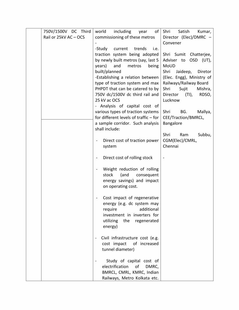
750V/1500V! DC! Third!Rail!or!25kV!AC!–!OCS!
!
!
world! including! year! of!commissioning!of!these!metros!'!'Study! current! trends! i.e.!traction! system! being! adopted!by!newly!built!metros!(say,!last!5!years)! and! metros! being!built/planned!'Establishing! a! relation! between!type!of!traction!system!and!max!PHPDT!that!can!be!catered!to!by!750V!dc/1500V!dc! third! rail! and!25!kV!ac!OCS!'! Analysis! of! capital! cost! of!various!types!of!traction!systems!for!different!levels!of!traffic!–!for!a!sample!corridor.!!Such!analysis!shall!include:!!' Direct!cost!of!traction!power!
system!!' Direct!cost!of!rolling!stock!!' Weight! reduction! of! rolling!
stock! (and! consequent!energy! savings)! and! impact!on!operating!cost.!
!' Cost! impact! of! regenerative!
energy! (e.g.! dc! system! may!require! additional!investment! in! inverters! for!utilizing! the! regenerated!energy)!
!'! ! Civil! infrastructure! cost! (e.g.!
cost! impact! ! of! increased!tunnel!diameter)!
!'! ! ! Study! of! capital! cost! of!
electrification! of! DMRC,!BMRCL,! CMRL,! KMRC,! Indian!Railways,!Metro! Kolkata! etc.!
Shri! Satish! Kumar,!Director! (Elec)/DMRC! –!Convener!!Shri! Sumit! Chatterjee,!Adviser! to! OSD! (UT),!MoUD!Shri! Jaideep,! Diretor!(Elec.! Engg),! Ministry! of!Railways/Railway!Board!Shri! Sujit! Mishra,!Director! (TI),! RDSO,!Lucknow!!Shri! BG.! Mallya,!CEE/Traction/BMRCL,!Bangalore!!Shri! Ram! Subbu,!CGM(Elec)/CMRL,!Chennai!!'!
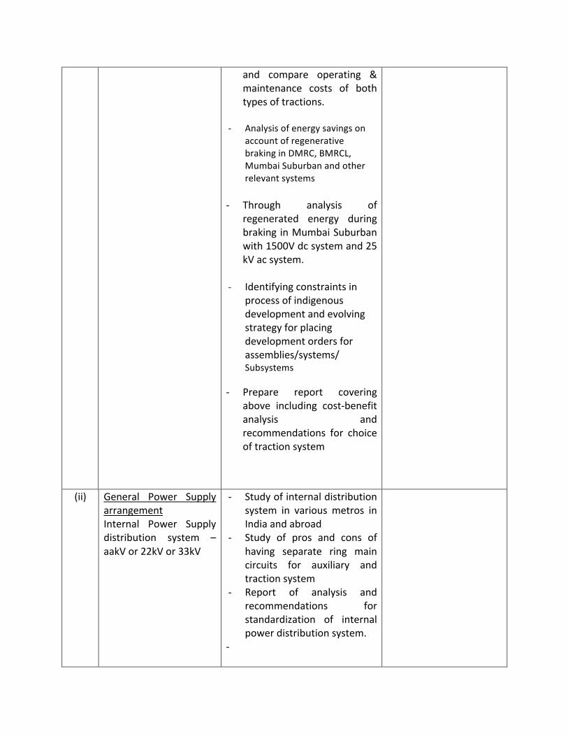
! and! compare! operating! &!maintenance! costs! of! both!types!of!tractions.!
!' Analysis!of!energy!savings!on!
account!of!regenerative!braking!in!DMRC,!BMRCL,!Mumbai!Suburban!and!other!relevant!systems!
!' Through! analysis! of!
regenerated! energy! during!braking!in!Mumbai!Suburban!with!1500V!dc!system!and!25!kV!ac!system.!
!' Identifying!constraints!in!
process!of!indigenous!development!and!evolving!strategy!for!placing!development!orders!for!assemblies/systems/!Subsystems!
' Prepare! report! covering!above! including! cost'benefit!analysis! and!recommendations! for! choice!of!traction!system!
!
!
(ii)! General! Power! Supply!arrangement!Internal! Power! Supply!distribution! system! –!aakV!or!22kV!or!33kV!
' Study!of!internal!distribution!system! in! various! metros! in!India!and!abroad!
' Study! of! pros! and! cons! of!having! separate! ring! main!circuits! for! auxiliary! and!traction!system!
' Report! of! analysis! and!recommendations! for!standardization! of! internal!power!distribution!system.!
' !!
!

(iii)! Energy! efficient!systems:'!BEE! certified/star! rated!Electric! system/Sub'syst4em,! use! of! LED!based!lighting/displays/signage!signaling! and! solar!based! system! in! station!area,! office! and!Commercial! building! of!Metro! system!Implementation!of!ECBC!Code!for!green!buildings!
Study!of!latest!trends!regarding!energy!efficiency!measures!Study! of! existing!policy/guidelines! regarding! use!of!energy!efficient!systems.!Study!of!possibilities!of!adoption!of! renewable! energy! systems!and! non'polluting! systems! in!metros.!!
!
!
4.! FICCI/CII/ASSOCHAM!will!nominate! representative!only! from!those! Industries!who!are!having!long!association!with!Design/manufacture!of!Rail!Based!rolling!stocks!with!three!phase!drive! (propulsions),! systems/sub'systems! infrastructures! i.e.! IGBT!based!propulsions/signaling!systems/Third! rail/overhead!electric! traction/AFC'ticketing!and!Power!supply!system!specially!used!in!Metro!Railways.!
5.! The! Sub'Committee! shall! submit! its! Report! within! one! month! (by! 21.8.2012)! to!Secretary!(UD),!Ministry!of!Urban!Development!from!the!date!of!issue!of!this!Order.!
Sd/'!(!DEEN!DAYAL!)!
Under!Secretary!to!the!Govt.!of!India!Tel.!23062935/Fax.!23062594!E'mail:[email protected]!!
!To!!! All!the!Members!of!the!Group!!Copy!for!information!and!necessary!action!to:'!!
1. Chairman,!Railway!Board,!Ministry!of!Railways,!Rail!Bhavan,!New!Delhi!2. Director! General,! Research! Development! &! Standards! Organization! (RDSO),!
Manaknagar,!Lucknow'226011!3. Managing!Director,!Delhi!Metro!Rail!Corporation!Ltd.,!Metro!Bhawan,!Fire!Brigade!Lane,!!
Barakhamba!Road,!New!Delhi'110001!

4. Managing! Director,! Bangalore!Metro! Rail! Corporation! Ltd.,! 3rd! Floor,! BMTC! Complex,!K.H.!Road,!Shanthinagar,!Bangalore'560!027!
5. Managing! Director,! Chennai! Metro! Rail! Ltd.,! “HARINI! TOWERS”,! No.7,! Conran! Smith!Road,!Gopalapuram,!Chennai'600!086!
6. Municipal! Commissioner,! Mumbai! Metropolitan! Region! Development! Authority!(MMRDA),! Bandra'Kurla! Complex,! Bandra! (East),!Mumbai'400051!with! the! request! to!nominate!one!officer!from!MMRDA!
7. Secretary,!FICCI,!Federation!House,!Tansen!Marg,!New!delhi'110001!8. Secretary,!Confederation!of!Indian!Industry!(CII),!23,!Vardman!Marg,!Institutional!Area,!
Lodi!Colony,!New!Delhi,!Delhi110003!9. Secretary,! Associated! Chambers! of! Commerce! and! Industry! of! India! (ASSOCHAM)!
Corporate!Office,!1,!Community!Centre!Zamrudpur,!Kailash!Colony,!New!Delhi'110!048!10. Shri! I.C.! Sharma,! National! Project! Manager,! Project! Management! Unit,! Sustainable!
Urban!Transport!Project!(SUTP),!Ministry!of!Urban!Development,!Nirman!Bhawan,!New!Delhi!
11. Smt.! R.! Dharini,! Deputy! Chief,! Ministry! of! Commerce! and! Industry,! Department! of!Industrial!Policy!&!Promotion,!National!Manufacturing!Competitiveness!Council,!Vigyan!Bhawan!Annexe,!New!Delhi!!
Copy!also!to!for!information:'!!
1. PS!to!UDM!2. Sr.!PPS!to!Secretary!(UD)!3. OSD!(UD)!&!e.o.!Joint!Secretary!4. Director!(UT)!5. Director!(MRTS'I)!6. Advisory!to!lOSD!(UT)!7. US!(MRTS'I)/US(MRTS'II)/US!(MRTS'III)/US!(MRTS'IV)!
!Sd/'!
(!DEEN!DAYAL!)!Under!Secretary!to!the!Govt.!of!India!

Annexure'I(B)'!
F.No.K'14011/26/2012'MRTS/Coord.!Government!of!India!
Ministry!of!Urban!Development!(MRTS!CELL)!
Room!No.311,!‘B’!Wing,!Nirman!Bhawan!New!Delhi'110108,!the!16th!August!2012.!
!OFFICE'MEMORANDUM'
!Sub:'Constitution'of'Sub=Committee'on'Traction'Systems'for'Metro'
! The! undersigned! is! directed! to! refer! to! this! Ministry’s! Order! of! even! No.! dated!25.07.2012! on! the! subject!mentioned! above! and! to! say! that! various! activities! for! this! study!have! been! identified! and! Shri! Satish! Kumar,! Direcor! (Electrical)! Delhi!Metro! Rail! Corporation!Ltd.! (DMRC)!has!been!nominated!as! the!Convener!of! the!Committee.! ! Shri!Anil! Jangid! is!also!being!nominated!as!one!of!the!Sub'Committee!ember.!
2.! In!this!connection,!some!base!paper!is!required!to!be!prepared!on!each!reference!item!to!begin!with!by!the!Members!of!the!Committee.!!Convener!of!the!Committee!has!nominated!t4he!following!officers!of!the!Sub'Committee!for!different!items!in!this!regard:'!
S.No.' Item'description' Nominated'Officer/Consultant'
1.1! Study! traction! systems! adopted! by! various!metros! around! the! world! including! year! of!commissioning!of!these!metros!!
Shri!Sujitt!Mishra!
1.2! Study!current!trends!i.e.!traction!system!being!adopted! by! newly! built! metros! (say,! last! 5!years)!and!metros!being!built/planned!!
'do'!
1.3! Establishing! a! relation! between! type! of!traction! system! and! max! PHPDT! that! can! be!catered!to!by!750V!dc/1500V!dc!third!rail!and!25!kV!ac!OCS!!
Shri!Sujit!Mishra!Shri!Anil!Jangid!!
1!
1.4! Analysis! of! capital! cost! of! various! types! of!traction!systems!for!different!levels!of!traffic!–!for! a! sample! corridor.! ! Such! analysis! shall!include:!
Shri!B.G.!Malya!Shri!Ram!Subbu!

!Direct!cost!of!traction!power!system!!1.4.2!Direct!cost!of!rolling!stock!!1.4.3! Weight! reduction! of! rolling! stock! (and!
consequent! energy! savings)! and! impact!on!operating!cost.!
!1.4.4!Cost! impact!of! regenerative!energy! (e.g.!
dc! system! may! require! additional!investment! in! inverters! for! utilizing! the!regenerated!energy)!
!1.4.5!Civil! infrastructure!cost! (e.g.! cost! impact!!
of!increased!tunnel!diameter)!!
1.5! Study!of!capital!cost!of!electrification!of!DMRC,!BMRCL,! CMRL,! KMRC,! Indian! Railways,!Metro!Kolkata! etc.! and! compare! operating! &!maintenance!costs!of!both!types!of!tractions.!!
Shri!Ram!Subbu!Shri!Sujit!Mishra!
1.6! Analysis! of! energy! savings! on! account! of!regenerative! braking! in! DMRC,! BMRCL,!Mumbai!Suburban!and!other!relevant!systems!!
Shri!Jaideep!Shri!B.G.!Malya!
1.7! Through!analysis!of!regenerated!energy!during!braking! in! Mumbai! Suburban! with! 1500V! dc!system!and!25!kV!ac!system.!!
Shri!Jaideep!
1.8! Identifying!constraints!in!process!of!indigenous!development!and!evolving!strategy!for!placing!development!orders!for!assemblies/systems/!Subsystems!!
Shri!B.G.!Malya!
!
1.9! Prepare! report! covering! above! including! cost'benefit! analysis! and! recommendations! for!choice!of!traction!system.!!
Shri!B.G.!Malya!Shri!Ram!Subbu!Shri!Sujit!Mishra!
2.1! Study!of!internal!distribution!system!in!various!metros!in!India!and!abroad!!
Sujit!Mishra!2!
2.2! Study!of!pros!and!cons!of!having!separate!ring! Shri!Sujit!Mishra!

main!circuits!for!auxiliary!and!traction!system!!
!
2.3! Report! of! analysis! and! recommendations! for!standardization! of! internal! power! distribution!system.!!
Shri!B.G.!Malya!
3.1! Study!of!latest!trends!regarding!energy!efficiency!measures!!
Shri!Anil!Jangid!!
3.2! Study! of! existing! policy/guidelines! regarding!use!of!energy!efficient!systems.!
Shri!Anil!Jangid!
3.3! Study!of!possibilities!of!adoption!of!renewable!energy! systems! and! non'polluting! systems! in!metros.!!
Shri!Anil!Jangid!
3!
3.4! Report!of!analysis!and!recommendations!!
!
42. A!meeting!of!the!above!mentioned!Sub'Committee!is!proposed!to!be!held!in!the!last!week!of!August!2012,!tentatively!on!28th!August!2012.! !The!exact!date,!time!and!venue!will!be!intimated!in!due!course.!
!
Sd/'!(!DEEN!DAYAL!)!
Under!Secretary!to!the!Govt.!of!India!Tel.No.23062935!
To!!
i) Shri!Sujit!Mishra,!Director!(TI),!RDSO,!Lucknow!(E'mail!ID:[email protected])!!ii) Shri!B.G.!Mallya,!CEE/Traction,!Bangalore!Metro!Rail!Corporation!Ltd.,!3rd!Floor,!BMTC!
Complex,! K.H.! Road,! Shanthinagar,! Bangalore'560! 027! (Fax! No.080'22969222)! (E'mail!ID:[email protected])!!!
iii) Shri! Ram! Subbu,! CGM! (Elec.),! Chennai! Metro! Rail! Limited! ,! “HARIJI! TOWERS”,! No.7,!Conran! Smith! Road,! Gopalapuram,! Chennai'600! 086! (E'mail! ID:! [email protected])!([email protected])!
iv) Shri! Jaideep,! Director! (Elec.! Engg),!Ministry! of! Railways,! Railway! Board,! Rail! Bhawan,!New!Delhi'110!001!(E'mail!ID:[email protected])!!
v) Shri! Anil! Jangid,! 301,! ONYXE! Tower,! Sector'21C,! Faridabad'121! 002! (E'mail! ID:[email protected])! !!!!

!Copy!to:!
i) Shri!Satish!Kumar,!Director!(Electrical),!Delhi!Metro!Rail!Corporation!Ltd.,!Fire!Brigade!Lane,!Barakhamba!Road,!New!Delhi'110!001!(E'mail!ID:[email protected])!!
ii) Adviser!(UT),!MoUD,!New!Delhi!(E'mail!ID:[email protected])!iii) Shri!I.C.!Sharma,!National!Project!Manager,!PMU!(SUTP),!Nirman!Bhawan,!New!Delhi!
Sd/'!(!DEEN!DAYAL!)!
Under!Secretary!to!the!Govt.!of!India!

!
Annexure – II
Global view of Traction System adopted by various World Metros
Sl.No.
City Country Date of commissioning
Network length
Stations Avg. station distance
Traction System Daily ridership
1 Adana Turkey 18 Mar 2009 13.5 km 13 1.125 m 750V dc OCS
2 Algiers Algeria 1 Nov 2011 7.3 km 10 1,000 m 750V dc third rail
3 Almaty Kazakhstan 1 Jan 2011 7.3 km 7 1,217 m 750V dc third rail
4 Amsterdam Netherlands 16 Oct 1977 32.7 km 33 1,128 750V dc third rail 233,000
5 Ankara Turkey 30 Aug 1996 23.1 km 23 1,100 m 750V dc third rail 310,000
6 Antwerp Belgium 25 Mar 1975 7. km 11 844 m 600V dc OCS
7 Athens Greece 1954 52.0 km 54 1,020 m 600V dc third rail (top collection)
937,000
8 Atlanta USA 30 Jun 1979 79.2 km 39 2,141 m 750V dc third rail 93,200
9 Baku Azerbaijan 6 Nov 1983 34.6 km 23 1,646 m 825V dc third rail 564,000
10 Baltimore USA 21 Nov 1983 24.5 km 14 1,885 m 700V dc third rail 37,500
11 Bangalore India 15 Sep 2011 7.5 km 6 1,500 m 750V dc third rail (bottom collection)!
12 Bangkok Thailand 5 Dec 1999 80.2 km 57 1,512 m 750V dc third rail (bottom collection)!
548,000

!
13 Barcelona Spain 11 Nov 1995
30 Dec 1924
43.4 km
76.0 km.
163 786 m 1500V dc rigid OCS(FGC)
1200V dc third rail
1.04 million
14 Beijing China 1 Oct 1969 337.0 km 196 1,842 m 750V dc third rail 5.97 million
15 Belo Horizonte Brazil 1 Aug 1986 28.1 km 19 1,563 m 3000V dc OCS 1,60,000
16 Berlin Germany 18 Feb 1902 147.4 km 195 797 m 750V dc third rail (top collection) 1.39 million
17 Bielefeld Germany 21 Sep 1971 5.2 km 7 1,733 m 750V dc OCS
18 Bilbao Spain 11 Nov 1995 43.4 km 40 1,142 m 1500V dc OCS 238,000
19 Bochum Germany 26 May 1979 21.5 km 29 797 m 660V dc OCS
20 Bonn Germany 22 Mar 1975 9.0 km 12 818 m 750V dc OCS
21 Boston USA 1 Sep 1897 60.5 km 66 960 m 600V dc OCS Green line), third rail 403,000
22 Brasilia Brazil 31 Mar 2001 42.0 km 24 1,826 m 750V dc third rail 151,000
23 Brussels Belgium 20 Sep 1976 32.2 km 61 555 m 900V dc third rail 364,000
24 Bucharest Romania 16 Nov 1979 69.3 km 50 1,505 m 825V dc third rail 485,000
25 Budapest Hungary 2 May 1896 33.0 km 42 846 m 825V dc, third line/600V dc OCS (Line M1)
827,000
26 Buenos Aires Argentina 1 Dec 1913 49.3 km 78 685 m 1500V DC OCS/1100V dc third rail (line B)
789,000

!
27 Buffalo USA 18 May 1985 10.3 km 15 1,194 m 650V dc OCS 23,200
28 Bursa Turkey 19 Aug 2002 31.5 km 31 1,086 m 1500V dc OCS
29 Busan South Korea 19 Jul 1985 131.8 km 127 1,080 m 1500V dc OCS/rigid 753,000
30 Cairo Egypt 27 Sep 1987 65.5 km 55 1,236 m
1500V dc OCS line 1
750V dc third rail other line
2.29 million
31 Caracas Venezuela 27 Mar 1983 60.5 km 50 1,344 m 750V dc third rail 1.33 million
32 Catania Italy 27 Jun 1999 3.8 km 6 760 m 3000V dc OCS
33 Changchun China Oct 2002 17.0 km 16 1,133 m 1500V dc OCS
34 Charleroi Belgium 21 Jun 1976 17.5 km 20 1,094 m 750V dc third rail!
35 Chengdu China 27 Sep 2010 18.5 km 16 1,233 m 750V dc third rail!
36 Chennai India 19 Oct 1997 27.0 km 17 1,688 m 25kV ac OCS
37 Chiba Japan 28 Mar 1988 15.5 km 18 969 m 750V dc mono rail
38 Chicago USA 6 Jun 1892 166.0 km 151 1,161 m 600V dc third rail 7,03,326
39 Chongqing China 18 Jun 2005 54.1 km 46 1,257 m 750V dc third rail 7,00,000
40 Cleveland USA 15 Mar 1955 31.0 km 18 1,824 m 600V dc OCS 14,000
41 Cologne Germany 11 Oct 1968 45.0 km 51 1,250 m 750V dc OCS
42 Copenhagen Denmark 19 Oct 2002 21.0 km 22 1,050 m 750V dc third rail/1500V dc OCS –
126,000

!
42 Copenhagen Denmark 19 Oct 2002 21.0 km 22 1,050 m 750V dc third rail/1500V dc OCS – one line
126,000
43 Daegu South Korea 26 Nov 1997 53.9 km 56 998 m 1500V dc OCS/rigid 315,000
44 Daejeon South Korea 16 Mar 2006 22.6 km 22 1,076 m 1500V dc OCS/rigid 95,900
45 Dalian China 1 May 2003 63.5 km 18 4,455 m 1500V dc OCS/rigid 1,20,000
46 Delhi India 24 Dec 2002 189 km 143 1,410 m 25kV ac OCS 2.0 million
47 Detroit USA Jul 1987 4.8 km 13 400 m 750V dc third rail
48 Dnepropetrovsk Ukraine 29 Dec 1995 7.1 km 6 1,420 m 825V dc third rail 38,400
49 Dortmund Germany 17 May 1976 29.5 km 37 866 m 600V dc OCS
50 Dubai United Arab Emirates
9 Sep 2009 69.7 km 45 1,621 m 750V dc third rail (bottom collection)
107,000
51 Dusseldorf Germany 4 Oct 1981 9.6 km 14 798 m 600V dc OCS
52 Duisburg Germany 11 Jul 1992 14.3 km 13 1,304 m 750V dc OCS
53 Edmonton Canada 22 Apr 1978 20.4 km 15 1,457 m 600V dc OCS 95,315
54 Essen Germany 5 Oct 1967 20.2 km 27 842 m 750V dc OCS
55 Frankfurt Germany 4 Oct 1968 20.5 km 31 732 m 750V dc OCS
56 Fukuoka Japan 26 Jul 1981 29.8 km 35 931 m 1500 dc OCS 340,000
57 Gelsenkirchen Germany 1 Sep 1984 5.5 km 9 690 m 600V dc OCS
58 Genoa Italy 13 Jun 1990 5.2 km 7 867 m 750V dc OCS

!
59 Glasgow United Kingdom 14 Dec 1896 10.4 km 15 743 m 600V dc third rail 41,100
60 Guadalajara Mexico 1 Sep 1989 24.0 km 29 889 m 750V dc OCS
61 Guangzhou China 28 Jun 1999 231.9 km 146 1,680 m
825V dc third rail
1500V dc OCS/third rail – bottom contact line 4 & 5 only
4.49 million
62 Gwangju South Korea 28 Apr 2004 20.1 km 20 1,058 m 1500V dc OCS/rigid 46,600
63 Haifa Israel 1959 1.8 km 6 350 m 700V dc third rail 8,000
64 Hamburg Germany 1 Mar 1912 100.7 km 97 1,071 m 1200V dc third rail 564,000
65 Hanover Germany 28 Sep 1975 18.6 km 21 1,033 m 600V dc OCS
66 Helsinki Finland 3 Aug 1982 21.0 km 17 1,313 m 750V dc third rail 199,340
67 Hiroshima Japan 20 Aug 1994 18.4 km 21 920 m 750V dc mono rail 49,300
68 Hong Kong Hong Kong S.A.R. 1 Oct 1979 175.0 km 95 2,059 m
1500V dc OCS MTR
25kV ac KCR 3.78 million
69 Incheon South Korea 6 Oct 1999 29.5 km 29 1,054 m 1500V dc OCS/rigid 219,000
70 Istanbul Turkey 16 Sep 2000 20.0 km 13 1,667 m 750V dc OCS, third rail (Line M2) 186,000
71 Izmir Turkey 22 May 2000 14.2 km 12 1,291 m 750V dc third rail 82,200
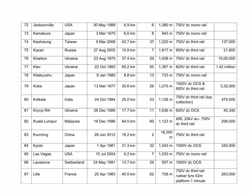
!
72 Jacksonville USA 30 May 1989 6.9 km 6 1,380 m 750V dc mono rail
73 Kamakura Japan 3 Mar 1970 6.6 km 8 943 m 750V dc mono rail
74 Kaohsiung Taiwan 9 Mar 2008 42.7 km 37 1,220 m 750V dc third rail 137,000
75 Kazan Russia 27 Aug 2005 10.9 km 7 1,817 m 850V dc third rail 21,900
76 Kharkov Ukraine 23 Aug 1975 37.4 km 29 1,438 m 750V dc third rail 10,00,000
77 Kiev Ukraine 22 Oct 1960 65.2 km 50 1,387 m 825V dc third rail 1.42 million
78 Kitakyushu Japan 9 Jan 1985 8.8 km 13 733 m 750V dc mono rail
79 Kobe Japan 13 Mar 1977 30.6 km 26 1,275 m 1500V dc OCS & 600V dc third rail 3,32,000
80 Kolkata India 24 Oct 1984 25.0 km 23 1,136 m 750V dc third rail (top collection) 474,000
81 Kryvyi Rih Ukraine 26 Dec 1986 17.7 km 11 1,636 m 600V dc OCS 45,340
82 Kuala Lumpur Malaysia 16 Dec 1996 64.0 km 60 1,123 m ARL 25kV ac– 750V dc third rail 299,000
83 Kunming China 28 Jun 2012 18.2 km 2 18,200 m 750V dc third rail
84 Kyoto Japan 1 Apr 1981 31.3 km 32 1,043 m 1500V dc OCS 345,000
85 Las Vegas USA 15 Jul 2004 6.2 km 7 1,033 m 750V dc mono rail
86 Lausanne Switzerland 24 May 1991 13.7 km 29 507 m 1500V dc OCS
87 Lille France 25 Apr 1983 45.5 km 62 758 m 750V dc third rail rubber tyre 52m platform 1 minute
263,000

!
87 Lille France 25 Apr 1983 45.5 km 62 758 m 750V dc third rail rubber tyre 52m platform 1 minute headway
263,000
88 Lisbon Portugal 29 Dec 1959 41.0 km 52 854 m 750V dc third rail 501,000
89 London United Kingdom 10 Jan 1863 402.0 km 270 1,552 m
750V dc third/
630V dc four rail 3.03 million
90 Los Angeles USA 30 Jan 1993 59.3 km 30 2,196 m 750V dc OCS, third rail (Red, Purple lines))
126,000
91 Ludwigshafen Germany 29 May 1969 4.0 km 11 364 m 600V dc
92 Lyon France 28 Apr 1978 30.7 km 43 787 m
Line C OCS 750V dc
and other third rail
685,000
93 Madrid Spain 17 Oct 1919 286.3 km 282 1,064 m 6000V dc rigid OCS,1500V dc rigid OCS
1.72 million
94 Manila Philippines 1 Dec 1984 51.5 km 44 1,256 m 750V dc OCS
1500V dc on one line 948,000
95 Maracaibo Venezuela 8 Jun 2009 6.5 km 6 1,300 m 1500V dc OCS, 72000 phpdt
96 Marseille France 26 Nov 1977 21.8 km 30 779 m 750V dc third rail 7,08,232
97 Mashhad Iran 10 Oct 2011 19.0 km 22 905 m 750V dc third rail 1,00,000

!
98 Mecca Saudi Arabia 13 Nov 2010 18.1 km 9 2,263 m
1500V dc catenary
72000 phpdt
99 Medellin Colombia 30 Nov 1995 28.8 km 26 1,200 m 1500V dc OCS 425,000
100 Mexico City Mexico 5 Sep 1969 201.7 km 175 1,230 m 750V dc third rail rubber tyre
4.38 million
101 Miami USA 21 May 1984 36.0 km 22 1,714 m 750V dc third rail 97,589
102 Milan Italy 1 Nov 1964 83.3 km 94 915 m
750V dc third rail Line M1
1500 V dc OCS
899,000
103 Minsk Belarus 26 Jun 1984 30.3 km 25 1,317 m 825V dc third rail 751,000
104 Monterrey Mexico 25 Apr 1991 31.5 km 32 1,050 m 1500 V dc OCS 378,000
105 Montreal Canada 14 Oct 1966 69.2 km 73 1,003 m 750V dc third rail 600,000
106 Moscow Russia 15 May 1935 306.2 km 185 1,770 m 825V dc third line 6.8 million
107 Mulheim Germany 3 Nov 1979 9.0 km 13 819 m 750V dc OCS
108 Mumbai India April 1853 171.0 km 73 2,515 m 1500V dc being converted to 25kV OCS
1.5 million
109 Munich Germany 19 Oct 1971 94.2 km 102 981 m 750V dc third rail 9,86,000
110 Nagoya Japan 15 Nov 1957 93.1 km 97 1,001 m 600V dc /1500V dc on Sakura – Dori line
1.17 million
111 Naha Japan 10 Aug 2003 12.8 km 15 914 m 750V dc mono rail

!
112 Nanjing China 27 Aug 2005 84.7 km 57 1,540 m 1500V dc OCS 1.33 million
113 Naples Italy 28 Mar 1993 31.8 km 30 1,178 m 1500V dc OCS 79,500
114 New York USA 27 Oct 1904 368.0 km 468 834 m 625,650 V dc (PATH), third rail 5 million
115 Newark USA 26 May 1935 2.2 km 4 733 m 750V dc third rail
116 Newcastle United Kingdom 7 Aug 1980 76.5 km 61 1,297 m 1500V dc OCS 1,13,000
117 Nizhny Novgorod Russia 20 Nov 1985 15.5 km 14 1,292 m 825V dc third rail 87,700
118 Novosibirsk Russia 7 Jan 1986 16.4 km 13 1,487 m 825V dc third rail 2,56,000
119 Nuremberg Germany 1 Mar 1972 36.0 km 48 800 m 750V dc third rail 337,000
120 Oporto Portugal 7 Dec 2002 21.7 km 15 1,669 m 750V dc OCS
121 Osaka Japan 20 May 1933 137.8 km 133 1,111 m 750,600 (Nanko Port Town Line) Third rail 2.29 million
122 Oslo Norway 22 May 1966 84.2 km 105 912 m 750V dc third rail 2,68,000
123 Palma de Mallorca Spain 25 Apr 2007 8.3 km 9 1,038 m 1500V dc OHE
124 Paris France 19 Jul 1900 215.0 km 381 589 m
750V dc third rail & fourth rail. RATP RER operates in 76.5 underground portion at 1500Vdc OCS
4.5 million

!
125 Perugia Italy 29 Jan 2008 3.0 km 7 500 m 750V dc third rail
126 Philadelphia USA 4 Mar 1907 62.0 km 66 984 m 600, 685 V dc (PATCO) third rail 192,000
127 Pittsburgh USA 3 Jul 1985 4.8 km 6 960 m 650V dc OCS 29,317
128 Porto Alegre Brazil 2 Mar 1985 33.8 km 17 2,112 m 3000V dc OCS
(Surface+elevated) 1,70,000
129 Poznan Poland 1 Mar 1997 6.1 km 6 1,220 m 750V dc third rail
130 Prague Czech Republic 9 May 1974 59.1 km 57 1,094 m 750V dc third rail 1.59 million
131 Pyongyang North Korea 6 Sep 1973 22.5 km 16 1,607 m 825V dc third rail 5,00,000
132 Recife Brazil 11 Mar 1985 39.7 km 30 1,418 m 3000V dc OCS
Mostly on surface 2,10,000
133 Rennes France 16 Mar 2002 9.0 km 15 643 m 750V dc third rail 121,000
134 Rio de Janeiro Brazil 5 Mar 1979 46.2 km 34 1,313 m 750V dc third rail 11,00,000
135 Rome Italy 10 Feb 1955 41.6 km 52 832 m 1500V dc OCS 9,07,000
136 Rotterdam Netherlands 10 Feb 1968 78.3 km 62 1,306 m
750V dc third rail
UG and OCS on surface
2,50,000
137 Rouen France 17 Dec 1994 2.2 km 5 550 m 1500V dc OCS
138 Saint Louis USA 31 Jul 1993 73.4 km 37 2,097 m 750V dc OCS 51,716

!
139 Saint Petersburg Russia 15 Nov 1955 110.2 km 65 1,837 m 825V dc third rail 2.13 million
140 Samara Russia 26 Dec 1987 10.2 km 9 1,275 m 825V dc third rail 52,100
141 San Francisco USA 11 Sep 1972 94.2 km 28
UG+24 surface
1,793 m 600V dc OCS 293,000
142 San Juan Puerto Rico 6 Jun 2005 17.2 km 16 1,147 m 750V dc third rail 26,300
143 Santiago Chile 15 Sep 1975 102.4 km 108 994 m 750V dc third rail 2.3
million
144 Santo Domingo Dominican Republic
30 Jan 2009 14.5 km 16 967 m 1500 V dc OCS 200,000
145 Sao Paulo Brazil 14 Sep 1974 74.3 km 67 1,198 m 750V dc third rail, 1500V dc OCS (Line 4-5)
2.07 million
146 Sapporo Japan 16 Dec 1971 48.0 km 49 1,043 m 1500, 750V dc OCS (Namboku Line), third line
573,000
147 Seattle USA 18 Jul 2009 27.8 km 12 2,018 m 750V dc/1500V dc catenary (2.5 km.)
148 Sendai Japan 15 Jul 1987 14.8 km 17 925 m 1500V dc OCS 159,000
149 Seoul South Korea 15 Aug 1974 316.3 km 293 1,114 m
1500V dc OCS/rigid
Sin Bundang and Ansan line 25kV ac
5.6 million

!
150 Seville Spain 2 Apr 2009 18.0 km 21 900 m 750V dc OCS 41,000
151 Shanghai China 10 Apr 1995 423.0 km 279 1,578 m 1500V dc OCS 5.16 million
152 Shenyang China 27 Sep 2010 49.5 km 41 1,268 m 750V dc third rail
153 Shenzhen China 28 Dec 2004 178.4 km 131 1,416 m
1500V dc OCS & third rail bottom contact on Longgang line only
362,000
154 Singapore Singapore 7 Nov 1987 146.5 km 100 1,526 m
750V dc third rail,
NE line 1500V dc OCS
2.04 million
155 Sofia Bulgaria 28 Jan 1998 20.2 km 16 1,347 m 825V dc third rail 79,500
156 Stockholm Sweden 1 Oct 1950 105.7 km 104 1,047 m
1500V dc (1912)
750V dc (1976). Actually fed at 900V dc due to great loss
849,000
157 Stuttgart Germany 10 Jun 1966 24.0 km 19 1,412 m 750V dc OCS
158 Suzhou China 29 Apr 2012 25.7 km 24 1,117 m 750V dc third rail
159 Sydney Australia 1926 22.1 km 14 2,005 m 750V dc third rail
160 Taipei Taiwan 28 Mar 1996 110.0 km 106 1,122 m 750V dc third rail 1.55 million
161 Tama Japan 27 Nov 1998 16.0 km 19 889 m 750V dc mono rail 16,978
162 Tashkent Uzbekistan 6 Nov 1977 36.2 km 29 1,392 m 825V dc third rail 200,000

!
163 Tbilisi Georgia 11 Jan 1966 26.3 km 22 1,315 m 825V dc third rail 241,000
164 Tehran Iran 21 Feb 2000 66.0 km 64 1,082 m 750V dc third rail 1.2 million
165 The Hague Netherlands 16 Oct 2004 27.9 km 30 1,033 m 750V dc OCS
166 Tianjin China 28 Mar 2004 72.0 km 37 2,057 m 825V dc third rail 41,100
167 Tokyo Japan 30 Dec 1927 304.5 km 290 1,099 m 1500, 600 V dc OCS (Ginza, Marunouchi lines)
8.7 million
168 Toronto Canada 30 Apr 1954 71.3 km 74 1,019 m 600V dc third rail 762,000
169 Toulouse France 26 Jun 1993 27.5 km 38 764 m 750V dc third rail 2,81,000
170 Turin Italy 4 Feb 2006 13.4 km 21 670 m 750V dc third rail 90,000
171 Valencia Spain 3 Oct 1988 31.8 km 38 909 m 1500V dc OCS
172 Valencia Venezuela 18 Oct 2006 6.2 km 7 1,033 m 750V dc OCS 57,500
173 Valparaiso Chile 23 Nov 2005 43.0 km 20 2,263 m 3000V dc OCS
174 Vancouver Canada 3 Jan 1986 69.5 km 49 1,511 m 600V dc third rail 321,000
175 Vienna Austria 25 Feb 1978 74.6 km 102 769 m 750V dc third rail/OCS 1.46 million
176 Volgograd Russia 5 Nov 1984 6.8 km 6 1,360 m 750V dc third rail
177 Warsaw Poland 7 Apr 1995 22.6 km 21 1,130 m 825V dc third rail 384,000
178 Washington USA 27 Mar 1976 171.2 km 90 2,014 m 750V dc third rail 595,000
179 Wuhan China 28 Sep 2004 28.0 km 27 1,076 m 750V dc third rail 200,000

!
180 Wuppertal Germany 1 Mar 1901 13.3 km 20 700 m 600V dc overhead rail (suspended rolling stock)
181 Xian China 16 Sep 2011 26.4 km 17 1,650 m 750V dc third rail
182 Yekaterinburg Russia 26 Apr 1991 12.7 km 8 1,814 m 750V dc third rail 134,000
183 Yerevan Armenia 7 Mar 1981 12.1 km 10 1,344 m 825V dc third rail 52,100
184 Yokohama Japan 16 Dec 1972 57.6 km 48 1280 m 750V dc third rail 542,000

Annexure – III
Details of Busiest World Metros in terms of Annual Ridership
Sl.No. City Country Network length (In km.)
Traction System Annual ridership (in billion)
1 Tokyo Subway Japan 304.5 1500V dc, 600V dc OCS 3,161 billion
2 Seoul Subway South Korea 316.3 1500V dc OCS/25kV AC
on Sin Bundang and Ansan Line
2.518 billion
3 Moscow Metro Russia 309.0 825V dc third rail 2.39 billion 4 Beijing Subway China 372.0 750V dc third rail 2.18 billion 5 Shanghai Metro China 424.8 1500V dc OCS 2.101bilion 6 New York City Subway USA 480.0 625V dc third rail 1.644 billion
7 Guangzhou Metro China 231.9 750V dc/third rail 1500V dc/third rail/OCS
1.64 billion
8 Paris Metro France 214.0 750V dc third rail 1.506 billion 9 Mexico City Metro Mexico 201.7 750V dc third rail 1.487 billion
10 Hong Kong Mass Transit Railway
Hong Kong S.A.R. 175.0 1500V dc OCS 1.482 billion
11 London Underground United Kingdom 442.0 630V dc four rail 1.171 billion
12 Cairo Metro Egypt 65.5 1500V dc OCS line – 1 750V dc third line 837 million
13 Osaka Subway Japan 137.8 750V dc third rail 600V dc third line
(Nanko Port Town line) 836 million
14 Sao Paulo Metro Brazil 74.3 750V dc third rail 811.7 million

Sl.No. City Country Network length (In km.)
Traction System Annual ridership (in billion)
1500V dc OCS Line 4-5 15 Saint Petersburg Metro Russia 110.2 825V dc third rail 786 million
16 Singapore Mass Rapid Transit Singapore 146.5 750V dc third rail 744.8 million
17 Santiago Metro Chile 102.4 750V dc third rail 639.9 million
18 Madrid Metro Spain 286.3 750V/1500V dc rigid/OCS 634.6 million
19 Milan Metro Italy 83.3`750V dc third
rail (Line-1) 1500V dc OCS
586 millon

Annexure-IV
A Global View of Commissioning of Metro Rail System since April 2007
S.No. Country City Commission- ing date
Network Length (in km.)
Stations Track gauge
Traction Special feature
1 Turkey Adana 14 May 2010 13.5 13 SG 750V dc OCS
Daily ridership 2.4 lakh, 3-car train, 15 minutes headway
2 Algeria Algiers 1 Nov 2011 9.0 10 SG 750V dc third rail
64 km. planned, 6-car train, CBTC, headway under 2 minutes
3 Kazakhstan Almaty 1 Jan 2011 7.3 7 1520 mm -do- 45 km. planned, 4 car train 4 India Bangalore 15 Sep 2011 7.5 6 SG -do- 42.3 km. planned in Phase I
with 8.8 km. underground, target 2013, designed for 3 minutes headway and 6 car train
5 India Delhi January 2010
April 2010 January 2011
Feb. 2011
6.17
15.15 20.16
22.70
5
14 16
6
BG
SG SG
SG
25kV ac
-do- -do-
-do-
Yamuna – Bank – Anand Vihar Line-4 Inderlok – Mundka Line-5 Central Secretariat-Badarpur Line-6 Airport Express Line
6 China Guangzhou Line-5
December 2009
31.9 24 SG 1500V dc third rail
Line-6 of 41.9 km. is also being constructed with 1500V dc third rail system and is likely to be commissioned in 2013
7 China Shenzhen Longgang Line
December 2010
41.66 30 SG -do- This is the only 1500V dc third rail which does not use linear induction motor in rolling stock
8 China Chengdu 27 Sep 2010 18.5 16 SG 750 V dc 126 km. planned in Phase I with

S.No. Country City Commission- ing date
Network Length (in km.)
Stations Track gauge
Traction Special feature
Third Rail 116 stations, target 2015, designed for 5-car operation
9 United Arab Emirates
Dubai 9 Sep 2009 69.7 45 SG -do- 12 lakh passengers per day, CBTC, 5-car train, 90 seconds headway, 96 km. more planned
10 Taiwan Kaohsiung 9 Mar 2008 42.7 SG -do- 3.8 lakh passengers per day, designed for 6-car rake
11 China Kunming 28 Jun 2012 18.2 SG -do- Airport Line with 6-car rake runs at 120 kmph, 83 km. planned in Phase I
12 Iran Mashhad 10 Oct 2011 19.0 SG
-do- 77 km. planned, Second line of 14 km. with 12 stations targeted in 2014, daily ridership - 1 lakh passengers
13 Saudi Arabia Mecca 13 Nov 2010 18.1 SG 1500V dc OCS
12-car train set, CBTC, designed for 72000 PHPDT
14 Spain Palma de Mallorca
25 Apr 2007 8.3 (5.7 km)
underground
9 MG 1500V dc OCS
6-car train, 11.8 km., planned with 15 stations
15 Italy Perugia 29 Jan 2008 3.0 7 SG 750V third rail
16 Dominican Republic
Santo Domingo
30 Jan 2009 14.5
16 SG 1500 V dc OCS
Daily ridership 2 lakh passengers; 6 car train, Line-2 planned for 22 km., part of which will be opened in 2012
17 USA Seattle 18 Jul 2009 27.8 12 SG 1500V dc (2.5 km.)/
3/4 car train, 2.5 km. underground in Central Line

S.No. Country City Commission- ing date
Network Length (in km.)
Stations Track gauge
Traction Special feature
750V dc OCS
18 South Korea Sin Bundang line
28 Oct 2011 17.3 6 SG 2x25 kV ac 60 Hz OCS
Driverless train operation CBTC
19 Spain Seville 2 Apr 2009 18.0 21 MG 1500V dc OCS
3-car train
20 China Shenyang 27 Sep 2010/2012
49.5 41 SG 750V third rail
21 China Suzhou 29 Apr 2012 25.7 24 (All under-
ground)
SG -do- 6-car train, 1.3 lakh passengers daily SG ridership
22 China Xian 16 Sep 2011 20.5 17 SG -do-
!

!
Annexure - V
Establishing relationship between type of traction & PHPDT
1.0 INTRODUCTION
1.1 Objective
The objective of this document is to perform preliminary study for working out maximum traffic capacity (PHPDT) for a sample section of metro railway with different traction system. no analysis is performed for 25kV ac system, as it is assumed any required PHPDT can be catered to with 25kV ac system.
1.2 Assumptions Sample section of 15km considered with station every 1km Design criteria – Failure of any one TSS should not affect the normal traffic operation Train of 6-car considered with passenger capacity of 2000 and overall weight of 350t (crush load) Starting acceleration of 1.0 m/s2 in 0-30 kmph speed range (to determine max power) Minimum acceptable line voltages are 500V and 1000V for 750V & 1500V dc system. The no-load voltage at TSS are assumed to be 800V & 1600V dc, hence the acceptable voltage drops are 300V and 600V respectively (as per IEC / EN)
1.3 Traffic Capacity (PHPDT) The theoretical traffic capacity would be as under: Table 1: Traffic capacity SN Headway No. of trains in one hour Traffic capacity (PHPDT)
1 3 min (180 sec) 20 nos. 40000
2 2.5 min (150 sec) 24 nos. 48000
3 2 min (120 sec) 30 nos. 60000
4 1.5 min (90 sec) 40 nos. 80000
1.4 750V dc System
1.4.1 System Modelling and assumptions
TSSs at last 2 stations on either side and then at alternate stations considered. Refer to figure 1 below.
Figure 1: TSS Configuration

!
It will be possible to add more TSSs to increase the traffic capacity, however, for the sake of this study, the above configuration would be considered limiting one and this will be tested for different headway as in Table 1 and the TSS sizing & voltage drop would be analysed. Traction system assumptions Conductor rail (composite) 4000A capacity (CMR)
0.007 Ω/km resistance
(will be 0.0035 Ω/km for two conductors rails bonded)
Running rails (UIC 60) All four rails cross bonded
0.0075Ω/km resistance
Loop impedance / km = 0.0035 + 0.0075
= 0.011 Ω/km
DC feeder cable 100m for each positive and negative connections
5 runs of 500 mm2 Cu cable
Resistance = 0.0015 Ω (approx)
Source impedance 0.015 Ω (3000kVA transformer with 8% impedance)
= 0.0075 Ω (two sets in parallel)
= 0.005 Ω (three set in parallel)
Total impedance (source + cable) = 0.009 Ω (approx) (two sets in parallel)
= 0.0065 Ω (three sets in parallel)
SEC 80 kWh/1000GTKM (assumed)
Regeneration Ignored for the purpose of capacity calculation
Train starting current 6000A
Hence: - Line voltage drop per train per km during starting = 0.011*6000 = 66 V - Voltage drop per accelerating train due to source impedance
o = 0.009*6000 = 54V (two sets in parallel) o = 0.0065*6000 = 39V (three sets in parallel)
1.4.2 TSS Rectifier Capacity for 1.5 min headway
The maximum power in one hour duration is worked out with the following considerations: o Sharing length for a TSS – This length is the average of the length on either side of a
TSS. This considers that each TSS has a feeding zone upto the middle point of a section between two consecutive TSSs.
o Number of trains in one hour duration for both directions – These are the total number of trains travelling in the ‘sharing length’ of a TSS, which represents the total load on a TSS in one hour duration.

!
Refer to Table below for the results of this calculation. As seen, the maximum power demand in one hour duration is 4480 kW for any of the TSS. Hence rectifier-transformer rating of 2*2.5 MW is adequate.
1.4.3 Voltage drop calculations
The following assumptions have been considered for these calculations: a. The currents shared by the adjacent substations are assumed to be in inverse proportion
to the distance of each train from them. b. It is assumed that a train departing from a station is fed from the traction substation at
that particular station for the entire duration of powering which may typically be over a period of half a minute.
c. The maximum power delivered by a substation is assumed to commence at the instant
when two trains simultaneously depart in opposite directions from a station where the traction substation is located.
The above assumptions only result in conservative scenarios.

!
Table-7: Rectifier-Transformer Capacity Calculation
Voltage V dc 750 750 750 750 750 750 750 750 750 Train Configuration M-T-M-M-T-M Maximum Current Imax Amp 6000 6000 6000 6000 6000 6000 6000 6000 6000 Train Weight (W) Tons 350 350 350 350 350 350 350 350 350 Specific Power Consumption (SFC) kWH/1000GTKM 80 80 80 80 80 80 80 80 80 Headway Minute 1.5 1.5 1.5 1.5 1.5 1.5 1.5 1.5 1.5 Number of Trains (N) Trains/hour 40 40 40 40 40 40 40 40 40
TSS1 TSS2 TSS3 TSS4 TSS5 TSS6 TSS7 TSS8 TSS9 L1 (km) Km 0.25 1 2 2 2 2 2 2 1 L2 (km) Km 1 2 2 2 2 2 2 1 0.25 Sharing Length L (km) Km 0.75 1.5 2 2 2 2 2 1.5 0.75 Max. power in 1 hour (Yn = SFC*W*L*N*2/1000 kW) kW 1680.0 3360.0 4480.0 4480.0 4480.0 4480.0 4480.0 3360.0 1680.0 Instantaneous Maximum power capacity (Zn = Yn + 1.7*√(Imax*Yn) kW
kW 7077.3 10993.0 13293.8 13293.8 13293.8 13293.8 13293.8 10993.0 7077.3
P1 (= Zn/3) kW 2359.1 3664.3 4431.3 4431.3 4431.3 4431.3 4431.3 3664.3 2359.1

!
With the design criteria of “one TSS outage not affecting the traffic”, the worst case scenario would be:
o TSS4 is in outage o Trains powering simultaneously at Station 6 to 9 (out of these trains 1 train each at Station 6 and 9 will
be fed from adjoining working TSS) It is shown in the figure below:
Figure 2: Worst case voltage drop scenario Therefore 6 trains will draw power from TSS5 i.e. 6*6000 = 36000A, which is beyond 1 minute rating of 5MW TSS (20000A), but can be met with 3*3000kW configuration. Line voltage drop = 66V (between station 6 and 7) = 2*66 = 132V (between station 7 and 8) = 198V total Voltage drop due to source impedance = 6*54 = 324V (two rectifiers in parallel) = 6*39 = 234V (three rectifiers in parallel) Hence, the total voltage drops far exceed 300V, therefore simultaneous 6 car powering cannot be catered to. The above configuration of TSS can cater to maximum three trains powering simultaneously. In practice, with headway of 2.5min, it is highly unlikely that any TSS will be required to power more than 3 trains simultaneously. Therefore, it can be preliminarily construed that the above configuration of TSS can cater to 2.5 min headway i.e. 48000 PHPDT. Beyond that headway / traffic capacity, 750V dc traction system may become inefficient solution, though theoretically more TSSs can be inserted to cater to additional demand.
1.5 1500V dc System
1.5.1 System Modelling and assumptions Conductor rail (composite) 2500A capacity (CMR)
0.012 Ω/km resistance
(will be 0.006 Ω/km for two conductors rails bonded)

!
Running rails (UIC 60) All four rails cross bonded
0.0075Ω/km resistance
Loop impedance / km = 0.006 + 0.0075
= 0.0135 Ω/km
DC feeder cable 100m for each positive and negative connections
3 runs of 500 mm2 Cu cable
Resistance = 0.0025 Ω (approx)
Source impedance 0.03 Ω (3000kVA transformer with 8% impedance)
= 0.015 Ω (two sets in parallel)
= 0.01 Ω (three set in parallel)
Total impedance (source + cable) = 0.0175 Ω (approx) (two sets in parallel)
= 0.0125 Ω (three sets in parallel)
SEC 80 kWh/1000GTKM (assumed)
Regeneration Ignored for the purpose of capacity calculation
Train starting current 3000A
Hence: - Line voltage drop per train per km during starting = 0.0135*6000 = 81 V - Voltage drop per accelerating train due to source impedance
o = 0.0175*3000 =52.5V (two sets in parallel) o = 0.0125*3000 = 37.5V (three sets in parallel)
1.5.2 TSS Rectifier Capacity for 1.5 min headway
This aspect is not a constraint in view of the analysis performed under Para 1.4.2 above.
1.5.3 Voltage drop calculations Assumptions are same as in Para 1.4.3. For the same number of TSS as in Para 1.4, the voltage drop would be: Line voltage drop = 81V (between station 6 and 7) = 2*81 = 162V (between station 7 and 8) = 243V total Voltage drop due to source impedance = 6*52.5 = 315V (two rectifiers in parallel)
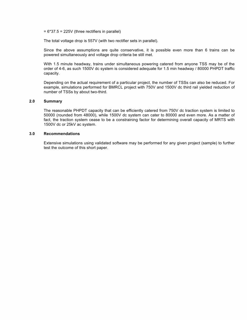
!
= 6*37.5 = 225V (three rectifiers in parallel) The total voltage drop is 557V (with two rectifier sets in parallel). Since the above assumptions are quite conservative, it is possible even more than 6 trains can be powered simultaneously and voltage drop criteria be still met. With 1.5 minute headway, trains under simultaneous powering catered from anyone TSS may be of the order of 4-6, as such 1500V dc system is considered adequate for 1.5 min headway / 80000 PHPDT traffic capacity. Depending on the actual requirement of a particular project, the number of TSSs can also be reduced. For example, simulations performed for BMRCL project with 750V and 1500V dc third rail yielded reduction of number of TSSs by about two-third.
2.0 Summary The reasonable PHPDT capacity that can be efficiently catered from 750V dc traction system is limited to 50000 (rounded from 48000), while 1500V dc system can cater to 80000 and even more. As a matter of fact, the traction system cease to be a constraining factor for determining overall capacity of MRTS with 1500V dc or 25kV ac system.
3.0 Recommendations Extensive simulations using validated software may be performed for any given project (sample) to further test the outcome of this short paper.
!

!
Annexure – VI
!
The O&M cost of DMRC for various lines over the last 5 years is as under:
( Rs. In lakhs ) S.No. Year Network Size (km) Total
O&M cost
Total O&M
Revenue
O&M cost/RKM
Revenue/RKM
1 2007-08 65.10 20035 31701 308 487 2 2008-09 74.56 22807 39287 306 527 3 2009-10 95.80 28899 52720 302 550 4 2010-11 160.87 48891 93865 304 583 5 2011-12 166.76 62785 128157 376 769
Earning per KM 487 527 550 583 769 Expenditure per KM 308 306 302 304 376 Operational Profit per KM 179 221 249 280 392
The Breakup of cost into various activities is as under:
O&M Cost (Rs. In Lakhs) S.No. Cost Head 2007-08 2008-09 2009-10 2010-11 2011-12
1 Staff Cost 8877.04 8666.21 11748.88 21573.83 26038.65 2 Energy Cost 4893.21 6731.47 7779.94 13439.85 20632.97 3 Maintenance Cost
(Excluding Store Consumed)
3032.92 3799.37 4316.91 6754.47 8231.32
4 Store Consumed 961.97 1159.95 2690.75 3047.17 5 Others 2270.3 2450.27 5052.91 4431.73 4834.79 Total 20035.44 22807.27 28898.64 48890.63 62784.90
!
!!!!!!!!!!!!!!!!!!!!!!!!!!!!!!!!!!!!!!!!!!!!!!!!!!!!!!!!!!!!!!!!!!!!!!

!
Annexure -VII
Operating Cost per Passenger Kilometer 2011 Prices US $ PPP
! !
!!!!!!!!!!!! !
NOVA has used purchasing power parity (PPP) Factors published by World Bank to normalize Financial Data for local costs and eliminate the effect of market rate fluctuations. In order to compare metros of all sizes on same scale, operating cost of metro has been evaluated by dividing the number of car kilometers, which respective metros operate.
Other!25!NOVA!Metros!
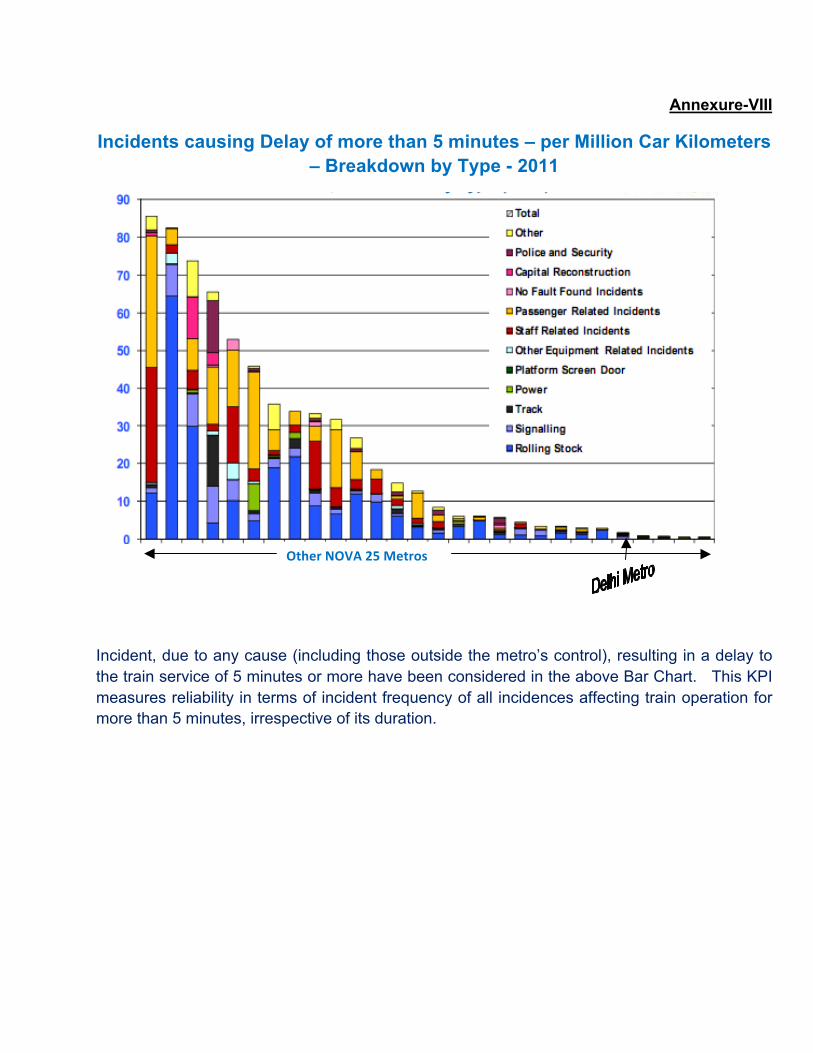
!
Annexure-VIII
Incidents causing Delay of more than 5 minutes – per Million Car Kilometers – Breakdown by Type - 2011
!
!!!!!!!!!!!!!!!!!!!!!!!!!!!!!!!!!!!!!!!!!!!!!!!!!!!!!!!!!!!!!!!!!!!!!!!!!!!!!!!!!!!!!!!!!!!!!!!!!!!!!!!!!!!!!!!!!!!!!!!!!!!!!!!!!!!!!!!!!!!!!!!!!!!!!! !
!
Incident, due to any cause (including those outside the metro’s control), resulting in a delay to the train service of 5 minutes or more have been considered in the above Bar Chart. This KPI measures reliability in terms of incident frequency of all incidences affecting train operation for more than 5 minutes, irrespective of its duration.
!
Other!NOVA!25!Metros!

!
Annexure IX
Estimated comparative cost of various traction systems for different PHPDT for sample corridor of 25km
Sl.No. Item 12,000 PHPDT 40,000 PHPDT 1 Total length
25.2 km. 25.2 km.
2 No. of 6-car train at a time
10 32
3 Power requirement
8 MW (DPR)
16.8 MW (BRCL base)
4 DC TSS No.
8 2x2 MVA
12 2x2.8 MVA
5 Receiving substation for TSS (i) 66 kV/33kV (ii) 110kV/33kV
2x13.5 OFAF 2x13.5 OFAF
2x30 OFAF 2x30 OFAF
6 Cost of receiving substation (Rs. In crore)
28 33
7 Cost of each TSS including civil work (Rs. In crore)
4.24 4.44
8 Total cost of DC TSS (Rs. in crore)
33.92 53.28
9 Cost of third rail (Rs. In crore)
55.44 55.44
10 Cost of earthing and stray current (Rs. In crore)
13.10 13.10
11 Lump sum cost of cable (Rs. In crore)
58 70
12
Estimated cost of Kochi Metro 750V dc traction system Sum of (6+8+9+10+11) (Rs. In crore)
188.46 224.82
13 (i) AC TSS capacity (ii) No.of TSS (iii) Cost per TSS (Rs. In crore)
2x13.5 OFAF 2
13.8
2X30 OFAF 2
15.8 14 Total cost of TSS
(Rs. In crore)
27.6 31.6

!
Sl.No. Item 12,000 PHPDT 40,000 PHPDT 15 Cost of sectioning/sub-sectioning post at the
rate of Rs. 60 lakh/per unit (Rs. In crore)
3.60 3.60
16 Cost of OHE at the rate of Rs. 44 lakh/per km. (Rs. In crore)
22.17 22.17
17 Lump sum cost of cable (Rs. In crore)
30 40
18 *Lump sum cost of auxiliary system (35% of total cost) (Rs. In crore)
83 90
19 Estimated cost of Kochi Metro with 25kV ac based on DPR for 12,000 PHPDT (Rs. In crore)
237.86 (as per DPR)
259.4
20 Estimated cost of 25kV ac traction system of Kochi Metro (19-18) (Rs. In crore)
154.86 169.4
21 Variation of 12 with respect to 20
17.8% 24.65%
1. Capacity of 6-car train – 2000 passengers and average speed 35 kmph. 2. Enhancement cost in RSS capacity has been taken as Rs.50 lakh per MW 3. *Estimation of 35% auxiliary system cost is based on DMRC experience of elevated
section !
!

Annexure-X
Comparative Energy Statement of 25kV ac & 750V dc rakes for 25km sample corridor
S.No. Item
6 car ac metro 3M+3T
existing
6 car dc metro 4M+2T
existing
(1) (2) (3) (4) 1 Operating speed - kmph 75 65 2 Weight in tonne 381.8 361 3 Passenger loading 2000 2000 4 Acceleration m/s2 0.82 1.0 5 Width (m) 3.2/2.9 2.88 6 Specific energy consumption
Kwh/1000 GTKM 48 61
7 PHPDT 48000 48000 8 Kilometer run 2x25 2x25 9 No. of trains 24 24
10 Energy consumed kwh for all trains of one round trip
21992 26425
11 %age Energy saving in trains 16.5 w.r.t. (4)
-
12 Energy supplied from substation including line losses (5% in ac & 16% in dc) in one hour
23091.5 30653
13 Net energy saving in one hour 7561.5 w.r.t. (4)
-
14 Total percentage saving including line losses
25 w.r.t. (4)
-
!

MEMO
DATE November 22, 2010
SUBJECT Comparison 25 k VA system against 750 V DC
FROM Ute Wiese
TO Mr. Anand - DMRC
CC Thomas Wittann, Karoly Csurgay, Sriram Raju Dear Mr. Anand, With regards to your request to provide you with a calculation of energy consumption based on an example of a 750 V DC we have prepared for you a vehicle simulation of energy consumption calculation comparing a 25 k VA and 750 V DC system and we send you the Singapore DTL energy consumption simulation (refer to “DOC951-XX-006-G.pdf”) for your information. The additional investigation has been done for three cases based on a Delhi 6-car train with 67% motorisation and a full round trip of 81.51 km (Line 4).
Kindly note that 100% regeneration in a DC system is highly unachievable. Calculations have hence been made for 750 V DC with 50% regeneration which is a realistic value. For more detailed information please see Annex 1 and 2. The Supply voltage is decided as a holistic approach considering the vehicle and the infrastructure.
With kind regards
Ute Wiese Product Manager Mass Transit, Product Management PASSENGERS Am Rathenaupark 16761 Hennigsdorf, Germany Tel.: +49 3302 89 –2172 Fax: +49 3302 89 - 1665 Mobile +49 174 926 2712 [email protected]
Annex 1: Input Data
Annexure-XI

2
Annex 2: Result Data for 50% regeneration

3

Annexure'XII''
1. Items in 750 V third rail traction, which can be considered for indigenization on an immediate basis:
(i) Third rail accessories like insulators and fixing brackets
(ii) Shroud for third rail
(iii) Dry type cast resin transformers of all ratings
(iv) Traction transformer and rectifier
2. Items for indigenization of 25 kV ac equipment (i) Light weight section insulator
(ii) Rigid OHE
(iii) Potential/ current transformer
(iv) Dry type auxiliary transformer
(v) Gas insulated sub-stations (GIS)
(vi) Certain imported OHE fittings
'
