tractor installation training guide - cetacea installation training guide mobile data terminal...
TRANSCRIPT

Tractor InstallationTraining Guide
Mobile Data Terminal 7000CEwith Hands-free Voice Kit
For FedEx Express truck models •Freightliner (Cascadia)
CONFIDENTIAL DOCUMENT Not for reproduction without expressed written permission. 1/13 csi/jw-jlf-wf-rm

• Consult the vehicle manufacturer guidelines regarding disconnection of the vehicle battery or when making supplementary electrical connections. • Before disconnecting a battery, understand the consequences to that vehicle, e.g. radio codes need to be available and know the reset procedure for airbag systems, ECU's etc. • Remove or cover any jewelry if working on live electrical systems. • Don't test electrical circuits using a test lamp. Use a high impedance multi-meter with both voltage and resistance ranges. • Don't tamper with or disconnect the air bag or SRS electrical harness.
Review these guidelines before installing the Locator or Mobile Data Terminal.
Electrical Safety and Wiring Guidelines
Electrical Safety
Locate or confirm power sources prior to disconnecting the vehicle battery. For all installations, the last step is applying power to the Locator. Make sure that all cabling has been completed before installing the Locator’s fuses. Disconnect the vehicle battery prior to making electrical connections.
Important Safety Guidelines
Review these guidelines before installing the Locator or Mobile Data Terminal (MDT)
2CONFIDENTIAL DOCUMENT Not for reproduction without expressed written permission. 1/13 csi/jw-jlf-wf-rm
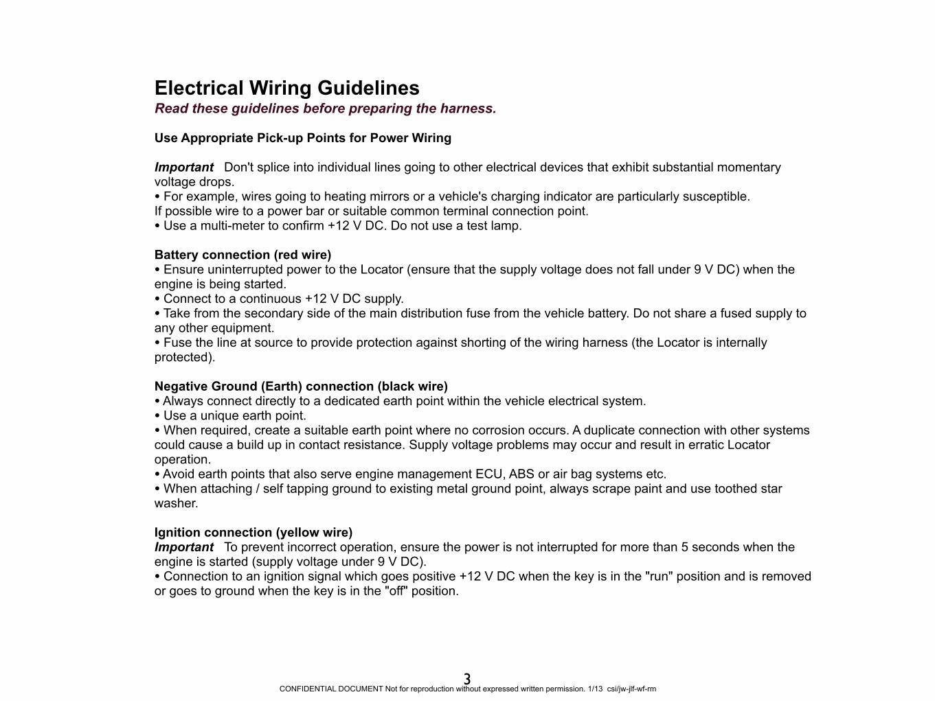
Electrical Wiring Guidelines Read these guidelines before preparing the harness.
Use Appropriate Pick-up Points for Power Wiring
Important Don't splice into individual lines going to other electrical devices that exhibit substantial momentary voltage drops. • For example, wires going to heating mirrors or a vehicle's charging indicator are particularly susceptible. If possible wire to a power bar or suitable common terminal connection point. • Use a multi-meter to confirm +12 V DC. Do not use a test lamp.
Battery connection (red wire) • Ensure uninterrupted power to the Locator (ensure that the supply voltage does not fall under 9 V DC) when the engine is being started. • Connect to a continuous +12 V DC supply. • Take from the secondary side of the main distribution fuse from the vehicle battery. Do not share a fused supply to any other equipment. • Fuse the line at source to provide protection against shorting of the wiring harness (the Locator is internally protected).
Negative Ground (Earth) connection (black wire) • Always connect directly to a dedicated earth point within the vehicle electrical system. • Use a unique earth point. • When required, create a suitable earth point where no corrosion occurs. A duplicate connection with other systems could cause a build up in contact resistance. Supply voltage problems may occur and result in erratic Locator operation. • Avoid earth points that also serve engine management ECU, ABS or air bag systems etc.• When attaching / self tapping ground to existing metal ground point, always scrape paint and use toothed star washer.
Ignition connection (yellow wire) Important To prevent incorrect operation, ensure the power is not interrupted for more than 5 seconds when the engine is started (supply voltage under 9 V DC). • Connection to an ignition signal which goes positive +12 V DC when the key is in the "run" position and is removed or goes to ground when the key is in the "off" position.
3CONFIDENTIAL DOCUMENT Not for reproduction without expressed written permission. 1/13 csi/jw-jlf-wf-rm
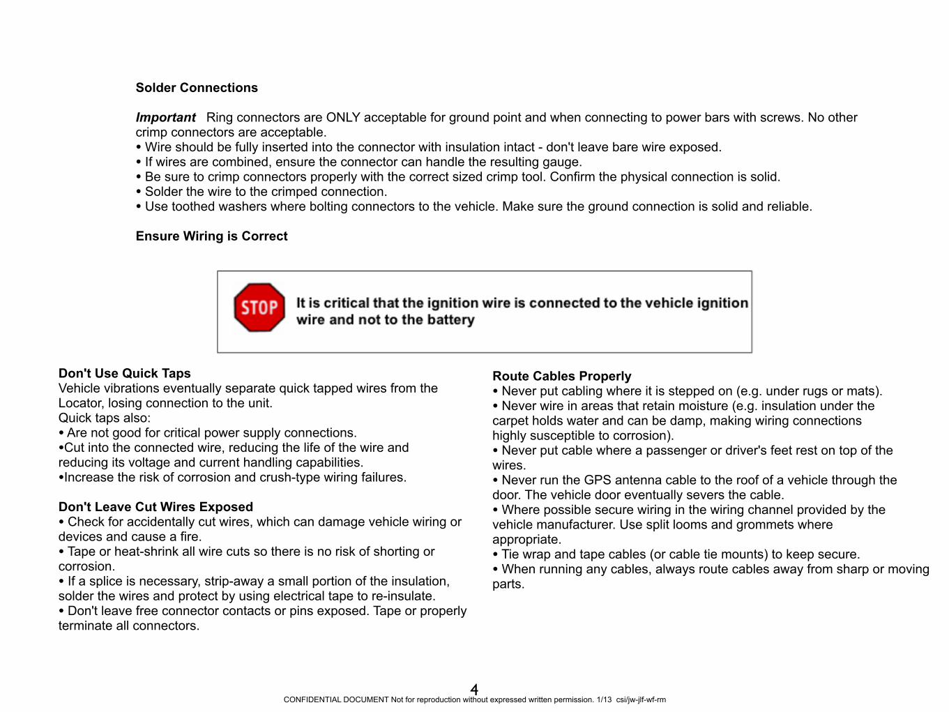
Solder Connections
Important Ring connectors are ONLY acceptable for ground point and when connecting to power bars with screws. No other crimp connectors are acceptable. • Wire should be fully inserted into the connector with insulation intact - don't leave bare wire exposed. • If wires are combined, ensure the connector can handle the resulting gauge. • Be sure to crimp connectors properly with the correct sized crimp tool. Confirm the physical connection is solid. • Solder the wire to the crimped connection. • Use toothed washers where bolting connectors to the vehicle. Make sure the ground connection is solid and reliable.
Ensure Wiring is Correct
Don't Use Quick Taps Vehicle vibrations eventually separate quick tapped wires from the Locator, losing connection to the unit. Quick taps also: • Are not good for critical power supply connections. •Cut into the connected wire, reducing the life of the wire and reducing its voltage and current handling capabilities. •Increase the risk of corrosion and crush-type wiring failures.
Don't Leave Cut Wires Exposed • Check for accidentally cut wires, which can damage vehicle wiring or devices and cause a fire. • Tape or heat-shrink all wire cuts so there is no risk of shorting or corrosion. • If a splice is necessary, strip-away a small portion of the insulation, solder the wires and protect by using electrical tape to re-insulate. • Don't leave free connector contacts or pins exposed. Tape or properly terminate all connectors.
Route Cables Properly • Never put cabling where it is stepped on (e.g. under rugs or mats). • Never wire in areas that retain moisture (e.g. insulation under the carpet holds water and can be damp, making wiring connections highly susceptible to corrosion). • Never put cable where a passenger or driver's feet rest on top of the wires. • Never run the GPS antenna cable to the roof of a vehicle through the door. The vehicle door eventually severs the cable. • Where possible secure wiring in the wiring channel provided by the vehicle manufacturer. Use split looms and grommets where appropriate. • Tie wrap and tape cables (or cable tie mounts) to keep secure.• When running any cables, always route cables away from sharp or moving parts.
CONFIDENTIAL DOCUMENT Not for reproduction without expressed written permission. 1/13 csi/jw-jlf-wf-rm4

CREATED BY:
CETACEA.COM 800.489.1759
CONTACT:
5CONFIDENTIAL DOCUMENT Not for reproduction without expressed written permission. 1/13 csi/jw-jlf-wf-rm
6CONFIDENTIAL DOCUMENT Not for reproduction without expressed written permission. 1/13 csi/jw-jlf-wf-rm
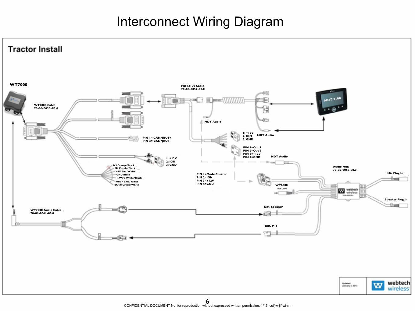
Interconnect Wiring Diagram
1: +12V2: IGN3: GNDPIN 1= CAN/JBUS+
PIN 2= CAN/JBUS-
MDT3100 Cable70-06-0052-00.0
1: +12V2: IGN3: GND
PIN 1=Out 1PIN 2=Out 2PIN 3=+12VPIN 4=GND
PIN 1=Mode ControlPIN 2=IGNPIN 3=+12VPIN 4=GND
MDT Audio
MDT Audio
WT6000Not Used
Diff. Speaker
Diff. Mic
Audio Mux70-06-0060-00.0
WT7000 Audio Cable70-06-0061-00.0
WT7000 Cable70-06-0036-R2.0
Mic Plug In
Speaker Plug In
N5 Orange/BlackN4 Purple/Black+5V Red/WhiteGND Black1-Wire White/Black
Out 7 Blue/WhiteOut 8 Green/White
MDT Audio
MDT 3100
WT7000
7CONFIDENTIAL DOCUMENT Not for reproduction without expressed written permission. 1/13 csi/jw-jlf-wf-rm
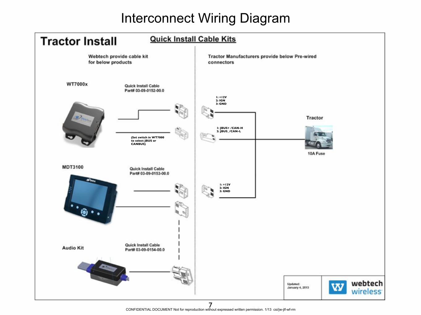
Interconnect Wiring Diagram
1: +12V2: IGN3: GND
1: +122: IGN3: GND
1: +12V2: IGN3: GND
1: JBUS+ /CAN-H2: JBUS_/CAN-L
(Set switch in WT7000 to select JBUS or CANBUS)

FedEx Express
Freightliner (Cascadia)
8CONFIDENTIAL DOCUMENT Not for reproduction without expressed written permission. 1/13 csi/jw-jlf-wf-rm

Dual-Mode Antenna
Microphone
Locator(Behind Panel)
Hookups(Behind Box)
MDT(w/Ram Mount)
Speaker
Mounting Locations
Dual-Mode Antenna
The dual mode GPS/GSM antenna mounts above the drivers head in the area shown above.
9
MDT(w/Ram Mount)
CONFIDENTIAL DOCUMENT Not for reproduction without expressed written permission. 1/13 csi/jw-jlf-wf-rm

Remove all parts and screws marked with an arrow.
Installing Dual-Mode GPS/GSM Antenna and Microphone
Carefully remove indicated parts to access roof over drivers head to install Dual-Mode Antenna.
Remove A-Pillar snap-on cover.
10CONFIDENTIAL DOCUMENT Not for reproduction without expressed written permission. 1/13 csi/jw-jlf-wf-rm

10”
12”
Clean roof around hole
Installing Dual-Mode GPS/GSM Antenna and Microphone (continued)
The dual mode GPS/GSM antenna mounts above the drivers head as shown to the left. After partially dropping the headliner on driver side, you will drill your hole as shown to the left. Apply a small bead of silicone immediately around the hole prior to installing antenna.
Dual-Mode AntennaOn the driver side of the roof, 10” from the edge of the fairing support bracket and 12” back from the front of the fairing drill 5/8” hole. Clean dirt and debris from around hole. Feed cable thru hole and install nut.
A n t e n n a M o u n t i n g Nut viewed from Inside
11CONFIDENTIAL DOCUMENT Not for reproduction without expressed written permission. 1/13 csi/jw-jlf-wf-rm

Installing Dual-Mode GPS/GSM Antenna and Microphone (continued)
Tie Antenna and Microphone Cables to existing cables routed down A-Pillar.
Use provided clip to mount microphone.
Completed mic installation show to the right.
Microphone
Secure with cable ties indicated by arrows moving down pillar.
12CONFIDENTIAL DOCUMENT Not for reproduction without expressed written permission. 1/13 csi/jw-jlf-wf-rm
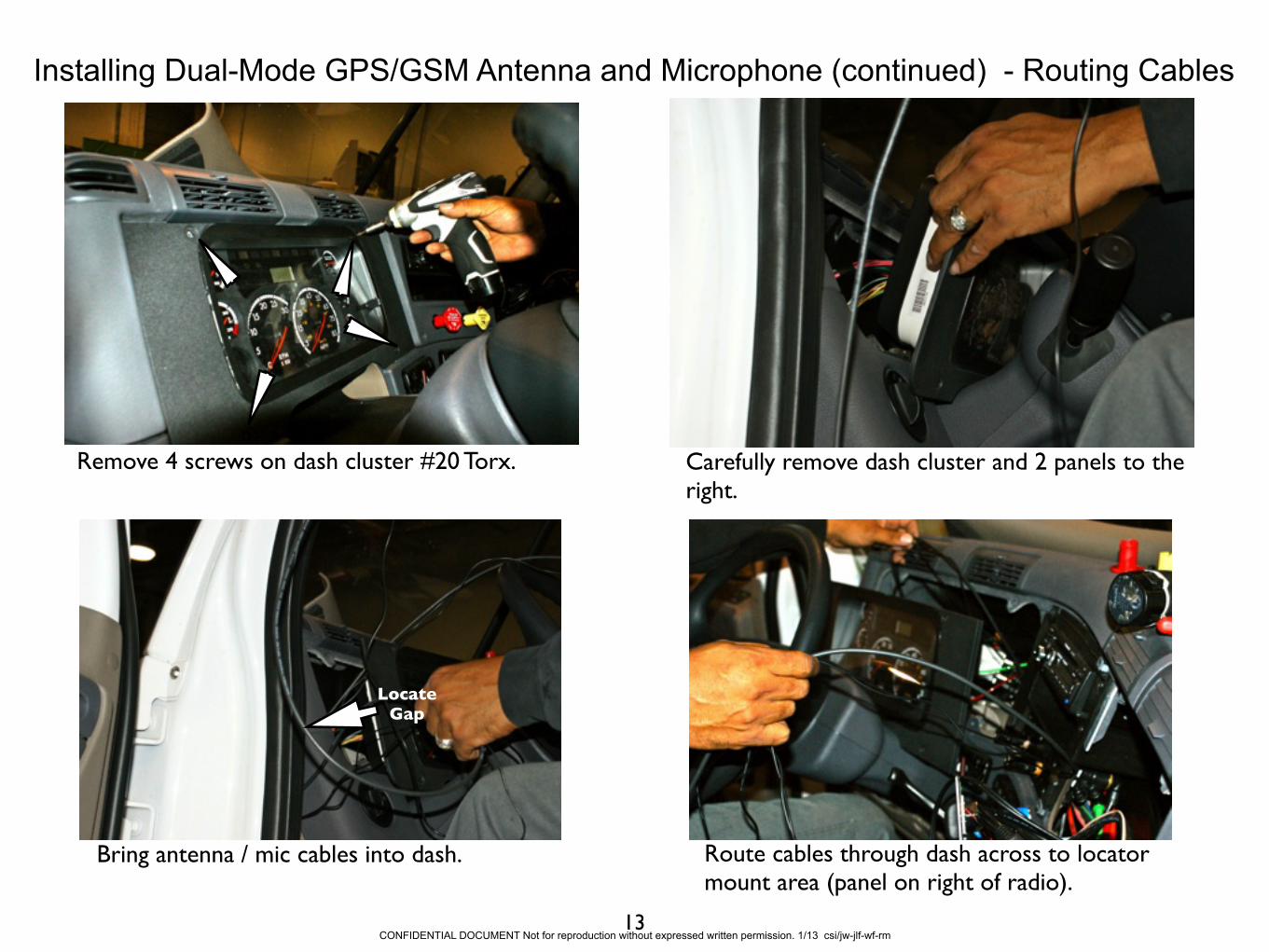
Installing Dual-Mode GPS/GSM Antenna and Microphone (continued) - Routing Cables
Remove 4 screws on dash cluster #20 Torx. Carefully remove dash cluster and 2 panels to the right.
Locate Gap
Bring antenna / mic cables into dash. Route cables through dash across to locator mount area (panel on right of radio).
13CONFIDENTIAL DOCUMENT Not for reproduction without expressed written permission. 1/13 csi/jw-jlf-wf-rm

Installing Power Adaptor Cable
Remove panels indicated by arrows.
Make power connections using supplied Cascadia Power Adaptor Cable.
Verify connections with a meter before proceeding! - Yellow/IGN to fuse position 24, Red/Constant to fuse position 22.
Remove existing fuse, insert removed fuse and 10A fuse provided in kit into fuse tap. Put fuse tap back into fuse slot.
12V+
IGN
Pos. 22
Pos. 24
Cascadia Power Adaptor Cable - Use self tapping screw to ground cable to metal strip in front of fuse panel.
Fuse Tap end of Power Adaptor Cable
14
Tapping ScrewToothed WasherRemove Paint
DO NOT make final molex connections yet.
CONFIDENTIAL DOCUMENT Not for reproduction without expressed written permission. 1/13 csi/jw-jlf-wf-rm

Installing J1939/Data Adaptor Cable
Location of J1939 Wires in Truck
Bring the WebTech 1939 Molex connector down to here from the locator mounting area. The Webtech 1939 cable will mate to the J1939 Adaptor Cable after you solder it to the.
Cascadia J1939/Data
Adapter Cable
You will solder the supplied J1939 Adaptor Cable at least 2” from the factory connector to the 1939 wires by peeling back the insulation one wire at a time and making the physical connection (solder). Cover each connection with electric tape. Connect green wire to green and yellow to yellow. See page 6 for connection to WebTech supplied Can Bus connector.
J1939/Data connections shown soldered. Existing cable may be gray or black.
15
1939 Cable Harness
Connection Point
CONFIDENTIAL DOCUMENT Not for reproduction without expressed written permission. 1/13 csi/jw-jlf-wf-rm

Installing MDT
Run MDT cable (coiled cable). The DB15 end goes to the locator area, the molex plug (Pwr/Gnd/Ign) goes into the fuse panel area (see diagram on pages 6 and 7). On either side of small connector (connects coiled cord to cord with DB15 connector), secure to an existing cable with pull ties to keep from pulling apart.
Hold backing plate in place as nuts / bolts installed
Using RAM mount base as a template, Mount RAM to panel as shown using backing plate, 4 lock nuts, bolts and washers.
16
Pull Ties
CONFIDENTIAL DOCUMENT Not for reproduction without expressed written permission. 1/13 csi/jw-jlf-wf-rm
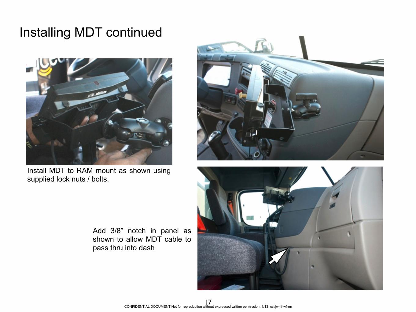
Installing MDT continued
Add 3/8” notch in panel as shown to allow MDT cable to pass thru into dash
Ram Mount
17
Install MDT to RAM mount as shown using supplied lock nuts / bolts.
CONFIDENTIAL DOCUMENT Not for reproduction without expressed written permission. 1/13 csi/jw-jlf-wf-rm

Installation of Speaker
Mark hole locations for speaker bracket in available area of panel. Verify nothing behind panel before drilling.
Attach speaker bracket using supplied lock nuts / bolts. Add 1/4” notch in both panels as shown.
Run speaker cable thru the notch and route cable to MUX “speaker in”. Tie excess speaker cable behind panel. Re-install panel.
Mount speaker to bracket.
Notch
18CONFIDENTIAL DOCUMENT Not for reproduction without expressed written permission. 1/13 csi/jw-jlf-wf-rm
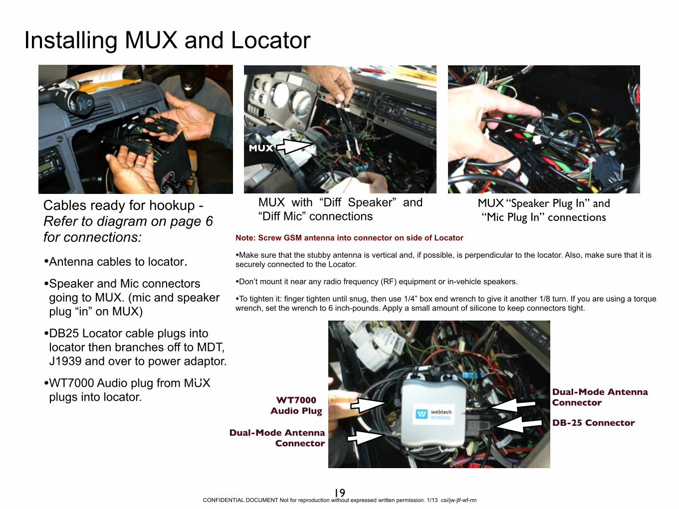
Installing MUX and Locator
MUX with “Diff Speaker” and “Diff Mic” connections
Ram Mount
Cables ready for hookup - Refer to diagram on page 6 for connections:
•Antenna cables to locator. •Speaker and Mic connectors going to MUX. (mic and speaker plug “in” on MUX)
•DB25 Locator cable plugs into locator then branches off to MDT, J1939 and over to power adaptor.
•WT7000 Audio plug from MUX plugs into locator.
DB-25 ConnectorDual-Mode Antenna
Connector
WT7000 Audio Plug
MUX “Speaker Plug In” and “Mic Plug In” connections
Dual-Mode Antenna Connector
19
MUX
CONFIDENTIAL DOCUMENT Not for reproduction without expressed written permission. 1/13 csi/jw-jlf-wf-rm
Note: Screw GSM antenna into connector on side of Locator
•Make sure that the stubby antenna is vertical and, if possible, is perpendicular to the locator. Also, make sure that it is securely connected to the Locator.
•Don’t mount it near any radio frequency (RF) equipment or in-vehicle speakers.
•To tighten it: finger tighten until snug, then use 1/4” box end wrench to give it another 1/8 turn. If you are using a torque wrench, set the wrench to 6 inch-pounds. Apply a small amount of silicone to keep connectors tight.

Final 1939 and Power Connections
Connect the 1939 Connector c o m i n g o f f t h e D B 2 5 connector from locator to the Cascadia J1939 adaptor cable installed previously.
Connect MDT Power connector and Locator Power Connector to the Cascadia Power Adaptor Cable installed previously.
20CONFIDENTIAL DOCUMENT Not for reproduction without expressed written permission. 1/13 csi/jw-jlf-wf-rm
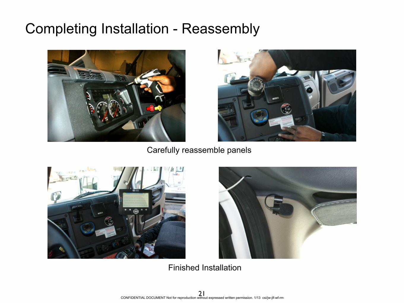
Completing Installation - Reassembly
Carefully reassemble panels
Finished Installation
21CONFIDENTIAL DOCUMENT Not for reproduction without expressed written permission. 1/13 csi/jw-jlf-wf-rm

Checkout and Verification
CONFIDENTIAL DOCUMENT Not for reproduction without expressed written permission. 1/13 csi/jw-jlf-wf-rm
Contact FedEx-First at 888.FDXTECH
Be prepared to supply tractor asset number and Webtech locator serial number.
Tractor should be parked outside with an unobstructed view of the sky and with ignition in the on position.
22

Tractor Installation
Training GuideMobile Data Terminal 7000CE
with Hands-free Voice Kit
For FedEx Express truck models •Freightliner (Cascadia)
CETACEA.COM 800.489.1759