tracvision tv1/rv1 lnb replacement instructions · 5 replacing a circular lnb follow the steps...
TRANSCRIPT

KVH, TracVision, and the unique light-colored dome with dark contrasting baseplate are registered trademarks of KVH Industries, Inc.All other trademarks are property of their respective companies. The information in this document is subject to change without notice. No company shall be liable for errors contained herein. © 2014 KVH Industries, Inc., All rights reserved. 54-0996 Rev. A
1
TracVision TV1/RV1 LNB
Replacement InstructionsTechnical Support
If you need technical assistance, please contact KVH Technical Support:
North/South America, Australasia:Phone: +1 401 847-3327E-mail: [email protected]
Europe, Middle East, Asia-Pacific, Africa:Phone: +45 45 160 180E-mail: [email protected]
The following instructions explain how to modify your TracVision® TV1/RV1 antenna to use a different LNB or replace a defective LNB.
Tools Required
This procedure requires the following tools:
• #2 Phillips torque screwdriver set to 15 in.-lbs
• Torque wrench and 2 mm Allen hex key
• Wire cutters
• 7/16" torque wrench set to 15 in.-lbs
• Laptop computer with the latest software downloaded via the KVH Partner Portal, or an Apple® iOS or Android™ smartphone/tablet with the latest software downloaded via the TracVision TV/RV mobile app
2
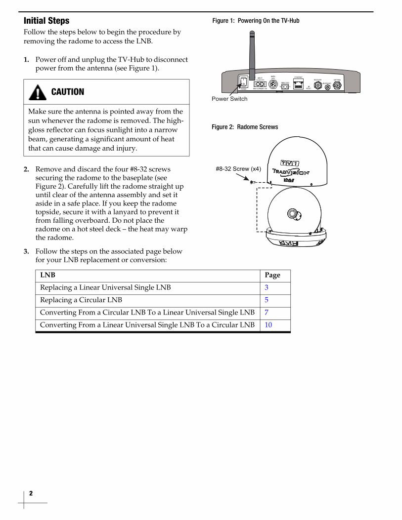
Initial Steps
Follow the steps below to begin the procedure by removing the radome to access the LNB.
1. Power off and unplug the TV-Hub to disconnect power from the antenna (see Figure 1).
2. Remove and discard the four #8-32 screws securing the radome to the baseplate (see Figure 2). Carefully lift the radome straight up until clear of the antenna assembly and set it aside in a safe place. If you keep the radome topside, secure it with a lanyard to prevent it from falling overboard. Do not place the radome on a hot steel deck – the heat may warp the radome.
3. Follow the steps on the associated page below for your LNB replacement or conversion:
CAUTION
Make sure the antenna is pointed away from the sun whenever the radome is removed. The high-gloss reflector can focus sunlight into a narrow beam, generating a significant amount of heat that can cause damage and injury.
LNB Page
Replacing a Linear Universal Single LNB 3
Replacing a Circular LNB 5
Converting From a Circular LNB To a Linear Universal Single LNB 7
Converting From a Linear Universal Single LNB To a Circular LNB 10
Figure 1: Powering On the TV-Hub
Power Switch
Figure 2: Radome Screws
#8-32 Screw (x4)
3
Replacing a Linear Universal Single LNB
Follow the steps below to replace a linear universal single LNB.
Removing the Old LNB
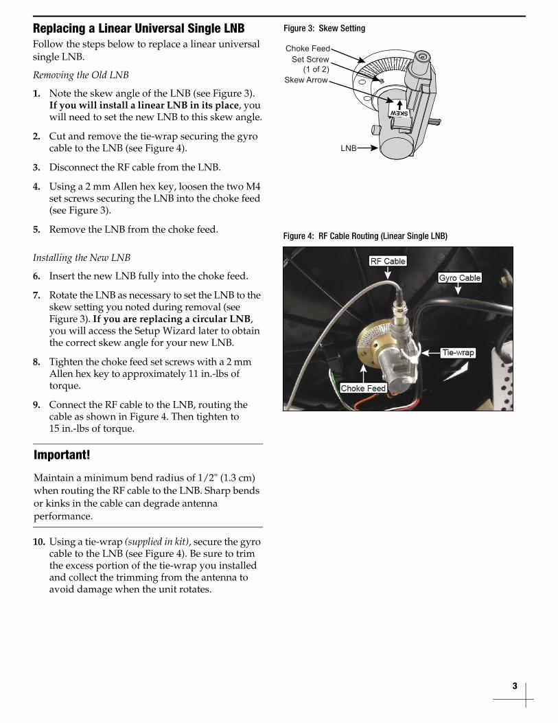
1. Note the skew angle of the LNB (see Figure 3). If you will install a linear LNB in its place, you will need to set the new LNB to this skew angle.
2. Cut and remove the tie-wrap securing the gyro cable to the LNB (see Figure 4).
3. Disconnect the RF cable from the LNB.
4. Using a 2 mm Allen hex key, loosen the two M4 set screws securing the LNB into the choke feed (see Figure 3).
5. Remove the LNB from the choke feed.
Installing the New LNB
6. Insert the new LNB fully into the choke feed.
7. Rotate the LNB as necessary to set the LNB to the skew setting you noted during removal (see Figure 3). If you are replacing a circular LNB, you will access the Setup Wizard later to obtain the correct skew angle for your new LNB.
8. Tighten the choke feed set screws with a 2 mm Allen hex key to approximately 11 in.-lbs of torque.
9. Connect the RF cable to the LNB, routing the cable as shown in Figure 4. Then tighten to 15 in.-lbs of torque.
10. Using a tie-wrap (supplied in kit), secure the gyro cable to the LNB (see Figure 4). Be sure to trim the excess portion of the tie-wrap you installed and collect the trimming from the antenna to avoid damage when the unit rotates.
Important!
Maintain a minimum bend radius of 1/2" (1.3 cm) when routing the RF cable to the LNB. Sharp bends or kinks in the cable can degrade antenna performance.
Figure 3: Skew Setting
+
0
–
10 2030 40 50 60 70
1020304050
6070
515253545
55
65
5 15 2535
45
5565
Choke Feed
Skew Arrow
Set Screw(1 of 2)
LNB
Figure 4: RF Cable Routing (Linear Single LNB)

4
11. Slowly rotate the antenna assembly through its elevation range to ensure neither the gyro cable nor the RF cable restrict the antenna’s movement.
12. Inspect the inside of the antenna to make sure you have not left any tools or debris inside.
13. Reinstall the radome onto the antenna, securing it with four new #8-32 screws (supplied in kit).
Reconnecting Power to the System
14. Reconnect power to the TV-Hub (see Figure 5).
15. Test the system for normal operation. If there is a problem, contact KVH Technical Support.
The procedure is complete!
Figure 5: Powering On the TV-Hub
Power Switch

5
Replacing a Circular LNB
Follow the steps below to replace a circular LNB.
Removing the Old LNB
1. Cut and remove the tie-wraps (labeled 1 and 2 in Figure 6) securing the gyro cable to the currently installed LNB.
2. Disconnect the RF cable from the LNB.
3. Remove and discard the four #8-32 screws securing the LNB and feed tube to the reflector (see Figure 7). Carefully remove the LNB, feed tube, and wavy washer (see Figure 8). Set them aside in a safe place.
Installing the New LNB
4. Center the wavy washer underneath the feed tube so that it does not interfere with the screws (see Figure 8). Then secure the LNB and the feed tube to the reflector using four new #8-32 screws (supplied in kit) and tighten to 15 in.-lbs of torque (see Figure 7).
5. Connect the RF cable to the LNB, routing the cable as shown in Figure 6. Then tighten to 15 in.-lbs of torque.
6. Using two tie-wraps (supplied in kit), secure the gyro cable to the LNB (see Figure 6). Be sure to trim the excess portion of the tie-wraps you installed and collect the tie-wrap trimmings from the antenna to avoid damage when the unit rotates.
Important!
Maintain a minimum bend radius of 1/2" (1.3 cm) when routing the RF cable to the LNB. Sharp bends or kinks in the cable can degrade antenna performance.
Figure 6: RF Cable Routing (Circular LNB)
Figure 7: #8-32 Screws
Figure 8: Wavy Washer and Feed Tube
Wavy Washer
Feed Tube
Choke Feed
6
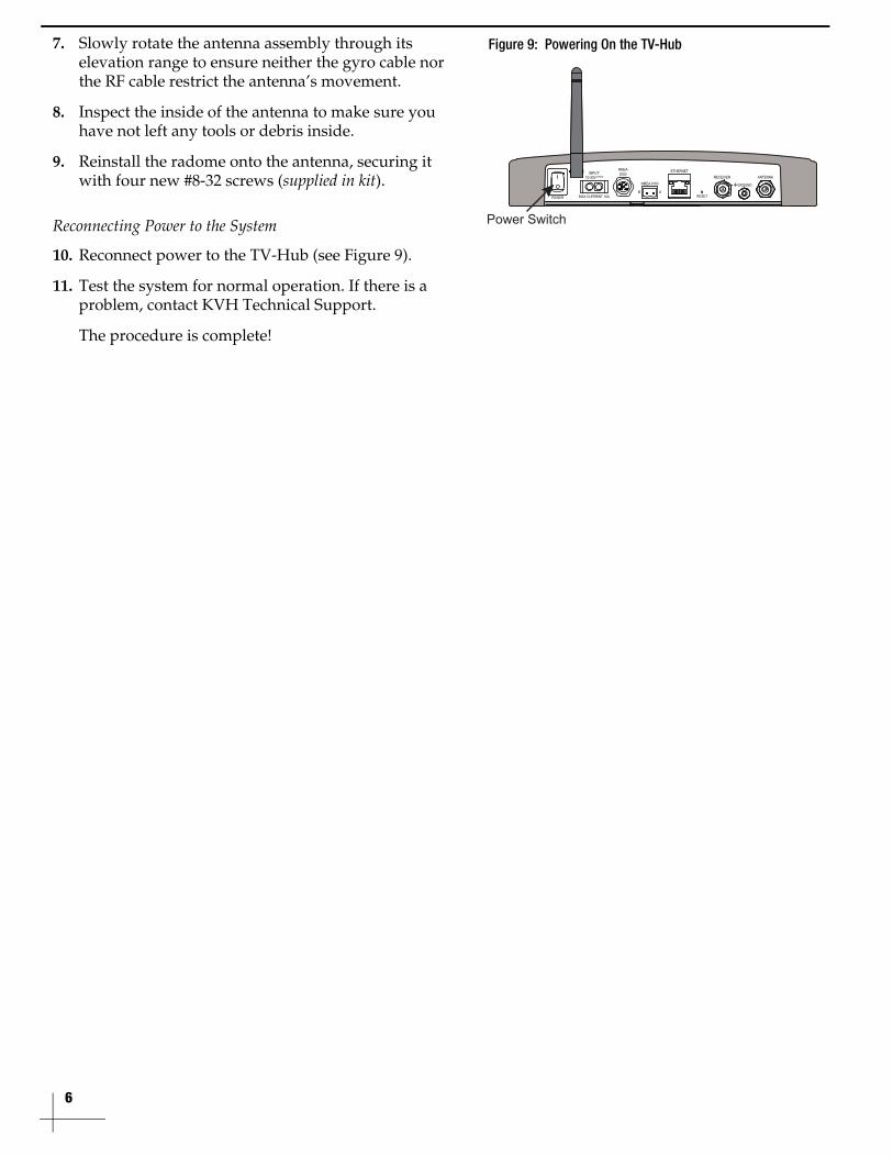
7. Slowly rotate the antenna assembly through its elevation range to ensure neither the gyro cable nor the RF cable restrict the antenna’s movement.
8. Inspect the inside of the antenna to make sure you have not left any tools or debris inside.
9. Reinstall the radome onto the antenna, securing it with four new #8-32 screws (supplied in kit).
Reconnecting Power to the System
10. Reconnect power to the TV-Hub (see Figure 9).
11. Test the system for normal operation. If there is a problem, contact KVH Technical Support.
The procedure is complete!
Figure 9: Powering On the TV-Hub
Power Switch
7
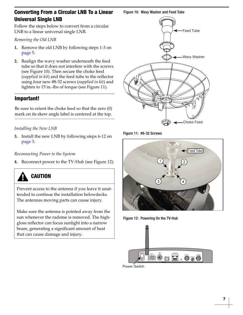
Converting From a Circular LNB To a Linear
Universal Single LNB
Follow the steps below to convert from a circular LNB to a linear universal single LNB.
Removing the Old LNB
1. Remove the old LNB by following steps 1-3 on page 5.
2. Realign the wavy washer underneath the feed tube so that it does not interfere with the screws (see Figure 10). Then secure the choke feed (supplied in kit) and the feed tube to the reflector using four new #8-32 screws (supplied in kit) and tighten to 15 in.-lbs of torque (see Figure 11).
Installing the New LNB
3. Install the new LNB by following steps 6-12 on page 3.
Reconnecting Power to the System
4. Reconnect power to the TV-Hub (see Figure 12).
Important!
Be sure to orient the choke feed so that the zero (0) mark on its skew angle label is centered at the top.
CAUTION
Prevent access to the antenna if you leave it unat-tended to continue the installation belowdecks. The antennas moving parts can cause injury.
Make sure the antenna is pointed away from the sun whenever the radome is removed. The high-gloss reflector can focus sunlight into a narrow beam, generating a significant amount of heat that can cause damage and injury.
Figure 10: Wavy Washer and Feed Tube
Wavy Washer
Feed Tube
Choke Feed
Figure 11: #8-32 Screws
Figure 12: Powering On the TV-Hub
Power Switch

8
Registering the New LNB
5. Connect your computer to the TV-Hub and access its web interface. (Refer to the TracVision system’s Quick Start Guide for details.)
6. Follow the instructions in the TracVision TV1/RV1 Help to update the system software to the latest version.
7. At the Support page of the web interface, select Command Line (see Figure 13).
8. At the command line, enter and send the following commands:
• HALT
• DEBUGON
• EEUNLOCK
9. After installation is complete and the TV-Hub confirms the new LNB has been loaded, enter and send the following command:
• ZAP
Important!
Commands entered into the command line must be typed exactly as they are printed below, including any spaces shown. Incorrectly typed commands could result in a critical error.
• ANTLNB,19-0444 Linear U,L,13/18V,10600,N,ON,9750,N,OFF
Figure 13: Command Line

9
Setting the Skew Angle
10. Reconnect to the TV-Hub web interface.
11. Select Settings and then select Setup Wizard.
12. Select Proceed with Setup Wizard on the Setup Wizard home page (see Figure 14).
13. From within the Setup Wizard, select satellite(s) to track.
14. Select a configuration and write down the proper skew angle.
15. Power off and unplug the TV-Hub to disconnect power from the antenna.
16. Loosen the set screws, then rotate the LNB as necessary to set the LNB to the skew setting you noted earlier (Figure 15). Tighten the set screws with a 2 mm Allen hex key to approximately 11 in.-lbs of torque.
17. Slowly rotate the antenna assembly through its elevation range a second time to ensure the skew angle does not effect the rotation. Adjust the cable routing as necessary.
18. Reinstall the radome onto the antenna, securing it with four new #8-32 screws (supplied in kit).
19. If you are converting to a circular LNB for DIRECTV service, disconnect your TV-Hub B and rewire the system to your new TV-Hub A. Refer to the TracVision TV1/RV1 Installation Guide(s) for details (supplied in kit).
20. Reconnect power to the TV-Hub.
Verifying Normal Operation
21. Test the system for normal operation. If there is a problem, contact KVH Technical Support.
The procedure is complete!
Figure 14: Setup Wizard
+
0
–
10 2030 40 50 60 70
1020304050
6070
515253545
55
65
5 15 2535
45
5565
Choke Feed
Skew Arrow
Set Screw(1 of 2)
LNB
Figure 15: LNB Skew Setting
10
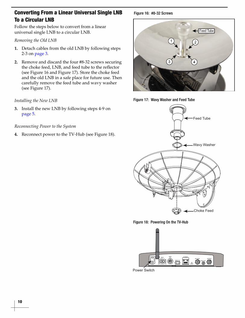
Converting From a Linear Universal Single LNB
To a Circular LNB
Follow the steps below to convert from a linear universal single LNB to a circular LNB.
Removing the Old LNB
1. Detach cables from the old LNB by following steps 2-3 on page 3.
2. Remove and discard the four #8-32 screws securing the choke feed, LNB, and feed tube to the reflector (see Figure 16 and Figure 17). Store the choke feed and the old LNB in a safe place for future use. Then carefully remove the feed tube and wavy washer (see Figure 17).
Installing the New LNB
3. Install the new LNB by following steps 4-9 on page 5.
Reconnecting Power to the System
4. Reconnect power to the TV-Hub (see Figure 18).
Figure 16: #8-32 Screws
Figure 17: Wavy Washer and Feed Tube
Wavy Washer
Feed Tube
Choke Feed
Figure 18: Powering On the TV-Hub
Power Switch
11
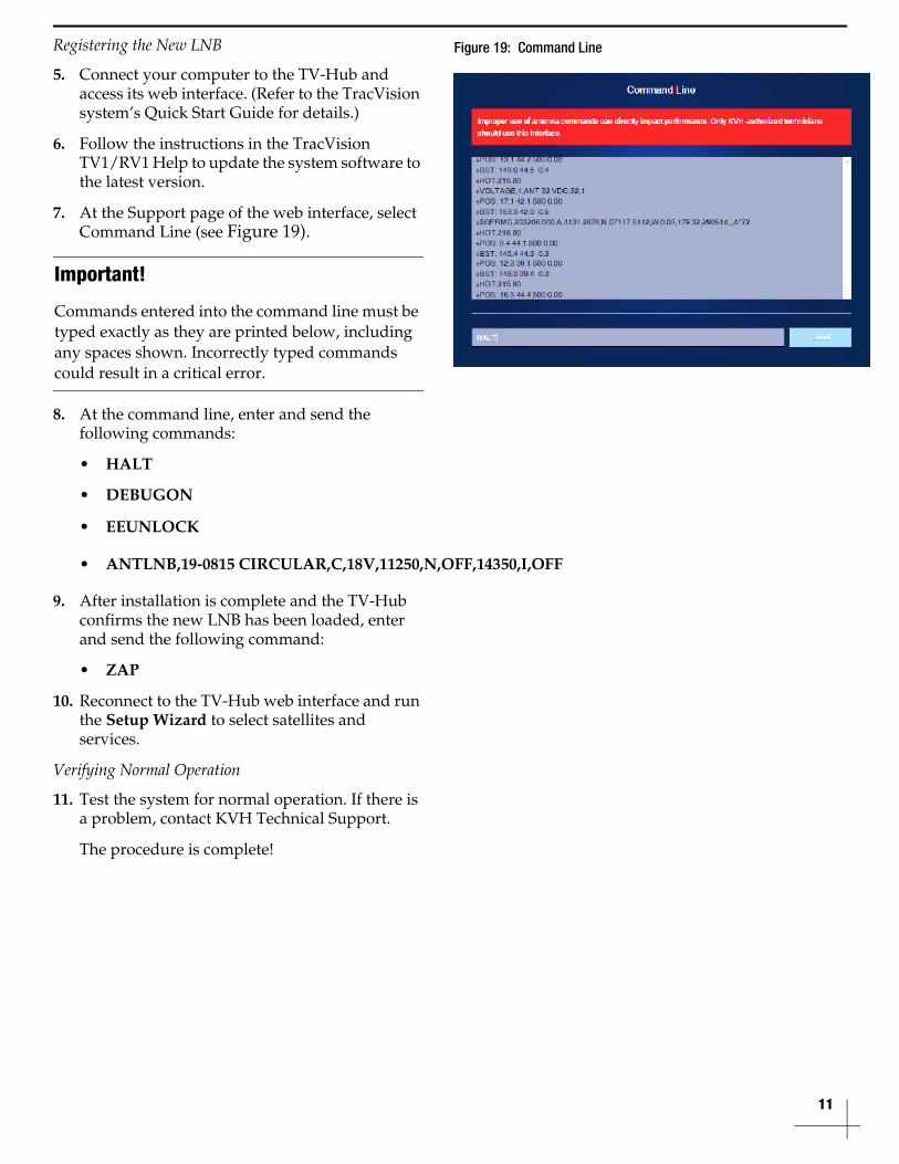
Registering the New LNB
5. Connect your computer to the TV-Hub and access its web interface. (Refer to the TracVision system’s Quick Start Guide for details.)
6. Follow the instructions in the TracVision TV1/RV1 Help to update the system software to the latest version.
7. At the Support page of the web interface, select Command Line (see Figure 19).
8. At the command line, enter and send the following commands:
• HALT
• DEBUGON
• EEUNLOCK
9. After installation is complete and the TV-Hub confirms the new LNB has been loaded, enter and send the following command:
• ZAP
10. Reconnect to the TV-Hub web interface and run the Setup Wizard to select satellites and services.
Verifying Normal Operation
11. Test the system for normal operation. If there is a problem, contact KVH Technical Support.
The procedure is complete!
Important!
Commands entered into the command line must be typed exactly as they are printed below, including any spaces shown. Incorrectly typed commands could result in a critical error.
• ANTLNB,19-0815 CIRCULAR,C,18V,11250,N,OFF,14350,I,OFF
Figure 19: Command Line