trade of electrician induction motor
TRANSCRIPT
Trade of Electrician
Standards Based Apprenticeship
Induction Motors
Phase 2
Module No. 2.4
Unit No. 2.4.1
COURSE NOTES
FAS Electrical Course Notes – Module 2.4.1
Revision 2 Nov 2006 2
-
Created by John Watters - Sligo TC
Revision 1 April 2000 by John Watters - Sligo TC Gerry Ryan - Galway TC
Revision 2 Nov 2006 by
Chris Ludlow - Dundalk TC
Published by
FÁS - Training and Employment Authority P.O. Box 456
27-33 Upper Baggot Street Dublin 4 Ireland
© FÁS - 2007
All rights reserved. No part of this publication may be reproduced, stored in a retrieval system or
transmitted in any form or by any means, electronic, mechanical, photocopying, recording or otherwise, without the prior permission of the copyright owner.
FAS Electrical Course Notes – Module 2.4.1
Revision 2 Nov 2006 3
Table of Contents INTRODUCTION .........................................................................................................................................4
ELECTRIC MOTORS..................................................................................................................................5
MOTOR RELATED I.E.C. SYMBOLS......................................................................................................6
THREE PHASE ( SQUIRREL CAGE ) INDUCTION MOTOR. ............................................................7
ROTOR SPEEDS.........................................................................................................................................15
REVERSING A THREE-PHASE INDUCTION MOTOR .....................................................................17
TESTING A THREE-PHASE INDUCTION MOTOR ...........................................................................18
METHODS OF STARTING THREE PHASE INDUCTION MOTORS ..............................................27
SINGLE PHASE INDUCTION MOTORS...............................................................................................29
TESTING A SINGLE PHASE INDUCTION MOTOR...........................................................................38
REVERSING A SINGLE PHASE INDUCTION MOTOR.....................................................................45
METHODS OF STARTING SINGLE PHASE INDUCTION MOTORS .............................................46

FAS Electrical Course Notes – Module 2.4.1
Revision 2 Nov 2006 4
Introduction Welcome to this section of your training course, which is designed to assist you the learner, understand the basics of how induction motors operate and how they are connected to the supply. Objectives By the end of this unit you will be able to:
• Understand the term induction motor. • Recognise and use induction motor symbols. • List the main parts of an induction motor. • Describe the construction of an induction motor. • State the characteristics of induction motors. • List methods of starting induction motors. • Decide how to connect the supply to an induction motor. • Calculate the synchronous speed of a given motor. • Understand that rotor speed is lower than synchronous speed. • Reverse the direction of rotation of a three phase induction motor. • Reverse the direction of rotation of a single phase induction motor. • Complete an electrical test on motor windings and any associated starting gear. • Understand the operation of a centrifugal switch.
Reasons Electric motors account for approximately two thirds of all electricity consumed. They are in common use in all areas of life, from work situations to leisure activities.
FAS Electrical Course Notes – Module 2.4.1
Revision 2 Nov 2006 5
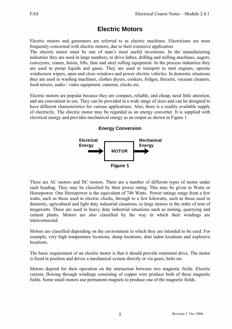
Electric Motors Electric motors and generators are referred to as electric machines. Electricians are most frequently concerned with electric motors, due to their extensive application. The electric motor must be one of man’s most useful inventions. In the manufacturing industries they are used in large numbers, to drive lathes, drilling and milling machines, augers, conveyors, cranes, hoists, lifts, fans and steel rolling equipment. In the process industries they are used to pump liquids and gases. They are used in transport to start engines, operate windscreen wipers, open and close windows and power electric vehicles. In domestic situations they are used in washing machines, clothes dryers, cookers, fridges, freezers, vacuum cleaners, food mixers, audio / video equipment, cameras, clocks etc. Electric motors are popular because they are compact, reliable, and cheap, need little attention, and are convenient to use. They can be provided in a wide range of sizes and can be designed to have different characteristics for various applications. Also, there is a readily available supply of electricity. The electric motor may be regarded as an energy converter. It is supplied with electrical energy and provides mechanical energy as an output as shown in Figure 1.
Energy Conversion
MOTOR
ElectricalEnergy
MechanicalEnergy
Figure 1
There are AC motors and DC motors. There are a number of different types of motor under each heading. They may be classified by their power rating. This may be given in Watts or Horsepower. One Horsepower is the equivalent of 746 Watts. Power ratings range from a few watts, such as those used in electric clocks, through to a few kilowatts, such as those used in domestic, agricultural and light duty industrial situations, to large motors in the order of tens of megawatts. These are used in heavy duty industrial situations such as mining, quarrying and cement plants. Motors are also classified by the way in which their windings are interconnected. Motors are classified depending on the environment in which they are intended to be used. For example, very high temperature locations, damp locations, dust laden locations and explosive locations. The basic requirement of an electric motor is that it should provide rotational drive. The motor is fixed in position and drives a mechanical system directly or via gears, belts etc.
Motors depend for their operation on the interaction between two magnetic fields. Electric current, flowing through windings consisting of copper wire produce both of these magnetic fields. Some small motors use permanent magnets to produce one of the magnetic fields.
FAS Electrical Course Notes – Module 2.4.1
Revision 2 Nov 2006 6
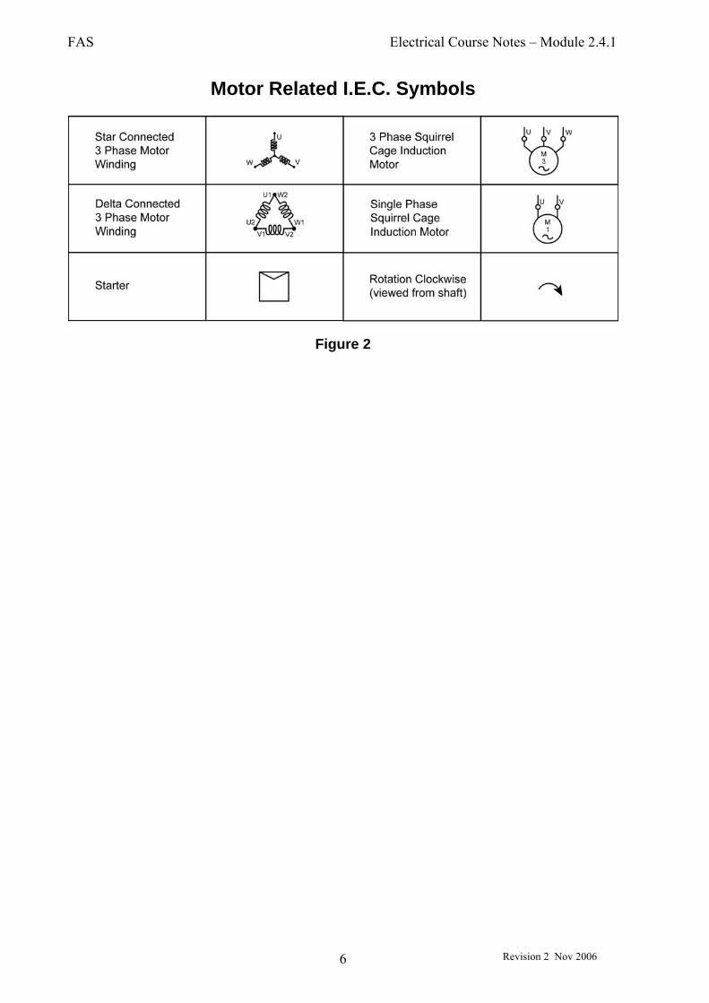
Motor Related I.E.C. Symbols
Figure 2
FAS Electrical Course Notes – Module 2.4.1
Revision 2 Nov 2006 7
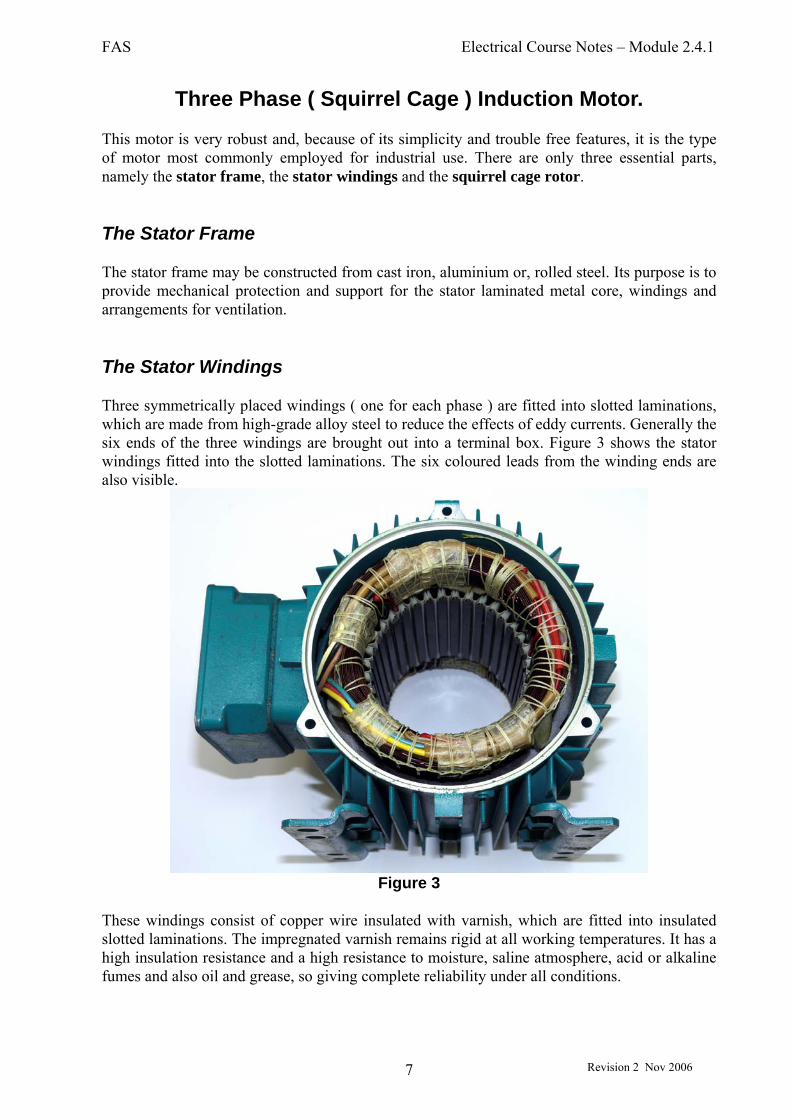
Three Phase ( Squirrel Cage ) Induction Motor. This motor is very robust and, because of its simplicity and trouble free features, it is the type of motor most commonly employed for industrial use. There are only three essential parts, namely the stator frame, the stator windings and the squirrel cage rotor. The Stator Frame The stator frame may be constructed from cast iron, aluminium or, rolled steel. Its purpose is to provide mechanical protection and support for the stator laminated metal core, windings and arrangements for ventilation. The Stator Windings Three symmetrically placed windings ( one for each phase ) are fitted into slotted laminations, which are made from high-grade alloy steel to reduce the effects of eddy currents. Generally the six ends of the three windings are brought out into a terminal box. Figure 3 shows the stator windings fitted into the slotted laminations. The six coloured leads from the winding ends are also visible.
Figure 3
These windings consist of copper wire insulated with varnish, which are fitted into insulated slotted laminations. The impregnated varnish remains rigid at all working temperatures. It has a high insulation resistance and a high resistance to moisture, saline atmosphere, acid or alkaline fumes and also oil and grease, so giving complete reliability under all conditions.
FAS Electrical Course Notes – Module 2.4.1
Revision 2 Nov 2006 8
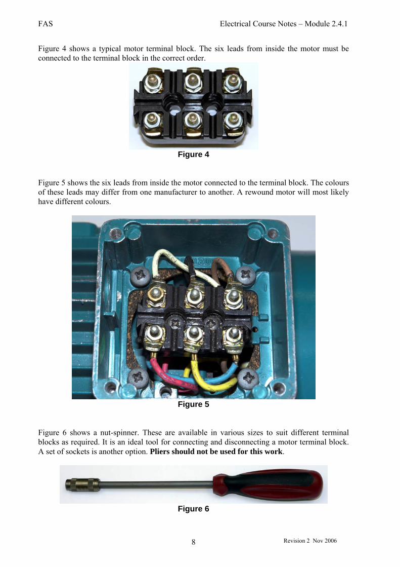
Figure 4 shows a typical motor terminal block. The six leads from inside the motor must be connected to the terminal block in the correct order.
Figure 4
Figure 5 shows the six leads from inside the motor connected to the terminal block. The colours of these leads may differ from one manufacturer to another. A rewound motor will most likely have different colours.
Figure 5
Figure 6 shows a nut-spinner. These are available in various sizes to suit different terminal blocks as required. It is an ideal tool for connecting and disconnecting a motor terminal block. A set of sockets is another option. Pliers should not be used for this work.
Figure 6
FAS Electrical Course Notes – Module 2.4.1
Revision 2 Nov 2006 9
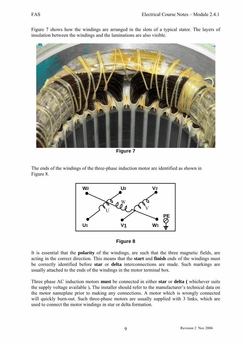
Figure 7 shows how the windings are arranged in the slots of a typical stator. The layers of insulation between the windings and the laminations are also visible.
Figure 7
The ends of the windings of the three-phase induction motor are identified as shown in Figure 8.
V W
U
W 2 U 2 V 2
V 1 W 1U 1
PE
Figure 8 It is essential that the polarity of the windings, are such that the three magnetic fields, are acting in the correct direction. This means that the start and finish ends of the windings must be correctly identified before star or delta interconnections are made. Such markings are usually attached to the ends of the windings in the motor terminal box. Three phase AC induction motors must be connected in either star or delta ( whichever suits the supply voltage available ). The installer should refer to the manufacturer’s technical data on the motor nameplate prior to making any connections. A motor which is wrongly connected will quickly burn-out. Such three-phase motors are usually supplied with 3 links, which are used to connect the motor windings in star or delta formation.
FAS Electrical Course Notes – Module 2.4.1
Revision 2 Nov 2006 10
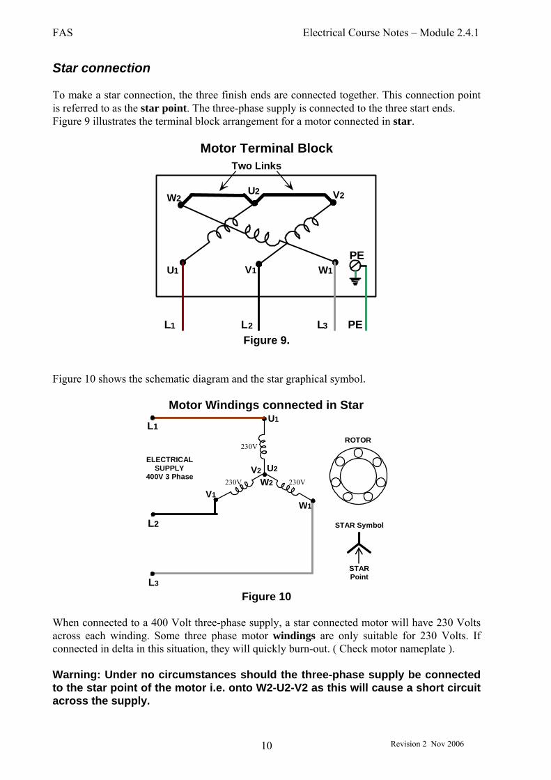
Star connection To make a star connection, the three finish ends are connected together. This connection point is referred to as the star point. The three-phase supply is connected to the three start ends. Figure 9 illustrates the terminal block arrangement for a motor connected in star.
Motor Terminal Block
W2 U2 V2
V1 W1
L 2
PE
Two Links
L 1 L 3 PE
U1
Figure 9.
Figure 10 shows the schematic diagram and the star graphical symbol.
230V230V
230V
W1
U1
U2
STAR Point
V1
L1
L2
L3
ELECTRICAL SUPPLY
400V 3 Phase
Motor Windings connected in Star
ROTOR
STAR Symbol
W2 V2
Figure 10
When connected to a 400 Volt three-phase supply, a star connected motor will have 230 Volts across each winding. Some three phase motor windings are only suitable for 230 Volts. If connected in delta in this situation, they will quickly burn-out. ( Check motor nameplate ). Warning: Under no circumstances should the three-phase supply be connected to the star point of the motor i.e. onto W2-U2-V2 as this will cause a short circuit across the supply.
FAS Electrical Course Notes – Module 2.4.1
Revision 2 Nov 2006 11
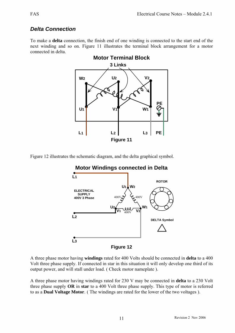
Delta Connection To make a delta connection, the finish end of one winding is connected to the start end of the next winding and so on. Figure 11 illustrates the terminal block arrangement for a motor connected in delta.
Motor Terminal Block
U2 V2
V1 W1
L2
PE
3 Links
L 1 L3 PE
W2
U1
Figure 11
Figure 12 illustrates the schematic diagram, and the delta graphical symbol.
400V
400V
400V
W1
U1 W2
V1
L1
L2
L3
ELECTRICAL SUPPLY
400V 3 Phase
Motor Windings connected in Delta
ROTOR
DELTA Symbol
U2V2
Figure 12
A three phase motor having windings rated for 400 Volts should be connected in delta to a 400 Volt three phase supply. If connected in star in this situation it will only develop one third of its output power, and will stall under load. ( Check motor nameplate ).
A three phase motor having windings rated for 230 V may be connected in delta to a 230 Volt three phase supply OR in star to a 400 Volt three phase supply. This type of motor is referred to as a Dual Voltage Motor. ( The windings are rated for the lower of the two voltages ).
FAS Electrical Course Notes – Module 2.4.1
Revision 2 Nov 2006 12
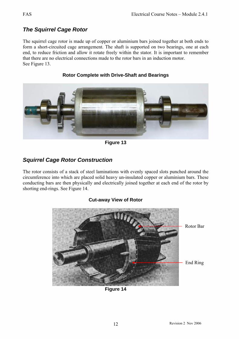
The Squirrel Cage Rotor The squirrel cage rotor is made up of copper or aluminium bars joined together at both ends to form a short-circuited cage arrangement. The shaft is supported on two bearings, one at each end, to reduce friction and allow it rotate freely within the stator. It is important to remember that there are no electrical connections made to the rotor bars in an induction motor. See Figure 13.
Rotor Complete with Drive-Shaft and Bearings
Figure 13
Squirrel Cage Rotor Construction The rotor consists of a stack of steel laminations with evenly spaced slots punched around the circumference into which are placed solid heavy un-insulated copper or aluminium bars. These conducting bars are then physically and electrically joined together at each end of the rotor by shorting end-rings. See Figure 14.
Cut-away View of Rotor
Figure 14
End Ring
Rotor Bar
FAS Electrical Course Notes – Module 2.4.1
Revision 2 Nov 2006 13
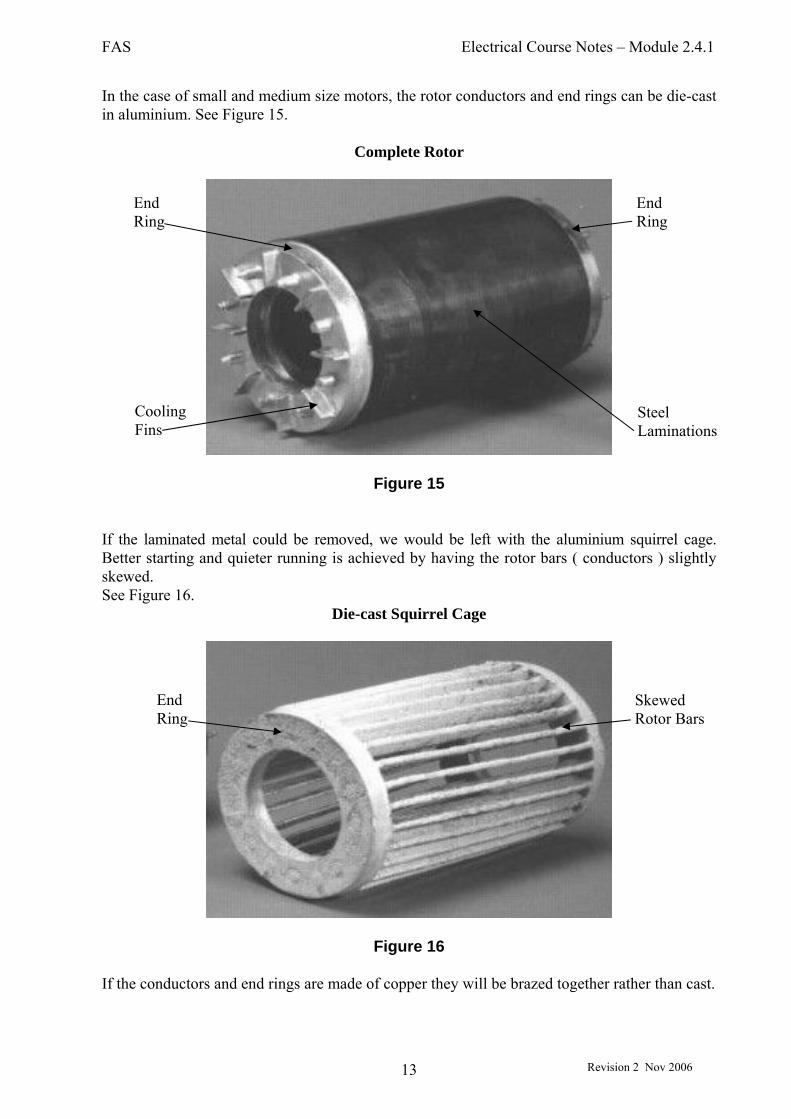
In the case of small and medium size motors, the rotor conductors and end rings can be die-cast in aluminium. See Figure 15.
Complete Rotor
Figure 15
If the laminated metal could be removed, we would be left with the aluminium squirrel cage. Better starting and quieter running is achieved by having the rotor bars ( conductors ) slightly skewed. See Figure 16.
Die-cast Squirrel Cage
Figure 16
If the conductors and end rings are made of copper they will be brazed together rather than cast.
End Ring
Steel Laminations
End Ring
Cooling Fins
End Ring
Skewed Rotor Bars
FAS Electrical Course Notes – Module 2.4.1
Revision 2 Nov 2006 14
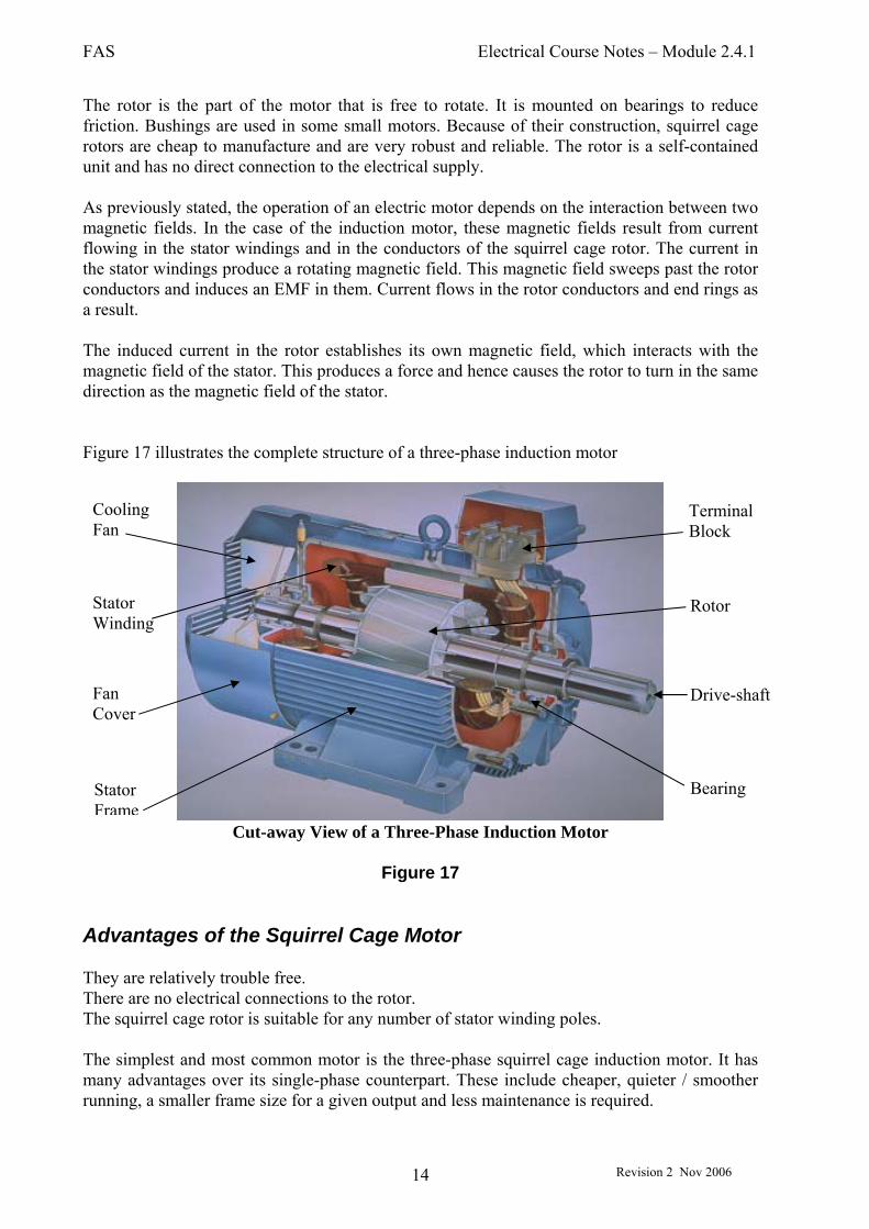
The rotor is the part of the motor that is free to rotate. It is mounted on bearings to reduce friction. Bushings are used in some small motors. Because of their construction, squirrel cage rotors are cheap to manufacture and are very robust and reliable. The rotor is a self-contained unit and has no direct connection to the electrical supply. As previously stated, the operation of an electric motor depends on the interaction between two magnetic fields. In the case of the induction motor, these magnetic fields result from current flowing in the stator windings and in the conductors of the squirrel cage rotor. The current in the stator windings produce a rotating magnetic field. This magnetic field sweeps past the rotor conductors and induces an EMF in them. Current flows in the rotor conductors and end rings as a result. The induced current in the rotor establishes its own magnetic field, which interacts with the magnetic field of the stator. This produces a force and hence causes the rotor to turn in the same direction as the magnetic field of the stator. Figure 17 illustrates the complete structure of a three-phase induction motor
Cut-away View of a Three-Phase Induction Motor
Figure 17
Advantages of the Squirrel Cage Motor They are relatively trouble free. There are no electrical connections to the rotor. The squirrel cage rotor is suitable for any number of stator winding poles. The simplest and most common motor is the three-phase squirrel cage induction motor. It has many advantages over its single-phase counterpart. These include cheaper, quieter / smoother running, a smaller frame size for a given output and less maintenance is required.
Rotor
Stator Frame
Drive-shaft
Stator Winding
Cooling Fan
Terminal Block
Fan Cover
Bearing
FAS Electrical Course Notes – Module 2.4.1
Revision 2 Nov 2006 15
Rotor Speeds When the stator windings are energised, they set up a rotating magnetic field which is referred to as the synchronous speed ( Ns ). This speed is measured in revolutions per minute ( RPM ). NB This is not the speed at which the motor shaft rotates. The speed of the rotating magnetic field depends on:
1. The frequency of the supply 2. The number of poles per winding in the motor
When considering the number of poles in a motor we only need to look at one of the windings. This applies to basic single phase and three phase induction motors. A winding will consist of an even number of poles. These poles are energised in pairs. A large number of poles around the stator will result in a slow speed motor. A winding cannot have less than two poles ( one pair of poles.). This results in the fastest possible motor speed for this type of motor. The synchronous speed may be determined by the following formula: f x 60
Ns = P
Where: Ns = The speed of the rotating magnetic field in RPM. f = The frequency of the supply in cycles per second ( Hz ).
60 = Converts cycles per second to cycles per minute. P = The number of Pairs of Poles per Winding in the motor.
Examples 1. The synchronous speed for a 2 pole motor operating at 50 Hz is:
f x 60 Ns =
P
50 x 60 Ns = Note 2 poles = 1 pair of poles.
1 Ns = 3000 RPM.
FAS Electrical Course Notes – Module 2.4.1
Revision 2 Nov 2006 16
2. The synchronous speed for a 4 pole motor operating at 50 Hz is:
f x 60 Ns =
P
50 x 60 Ns = Note 4 poles = 2 pair of poles.
2 Ns = 1500 RPM. 3. The synchronous speed for a 6 pole motor operating at 50 Hz is:
f x 60 Ns =
P
50 x 60 Ns = Note 6 poles =3 pair of poles.
3
Ns = 1000 RPM. 4. The synchronous speed for an 8 pole motor operating at 50 Hz is:
f x 60 Ns =
P
50 x 60 Ns = Note 8 poles =4 pair of poles.
4
Ns = 750 RPM. The synchronous speed in turn determines the rotor speed. As can be seen from the above calculations the greater the number of poles in the motor, the slower the output speed. The rotor speed is between 2.5% and 5.5% slower than the synchronous speed at full load. This is the speed which is given on the motor nameplate. The no load speed of a motor will be slightly higher than the full load speed. A squirrel cage induction motor can be considered to be a constant speed motor, as its speed varies only a small percentage with variations in load. Typical rotor speeds for squirrel cage induction motors are:
• 2850 RPM 2 pole motor 2nd most common speed. • 1425 RPM 4 pole motor most common speed. • 950 RPM 6 pole motor 3rd most common speed. • 712 RPM 8 pole motor slow speed applications.
FAS Electrical Course Notes – Module 2.4.1
Revision 2 Nov 2006 17
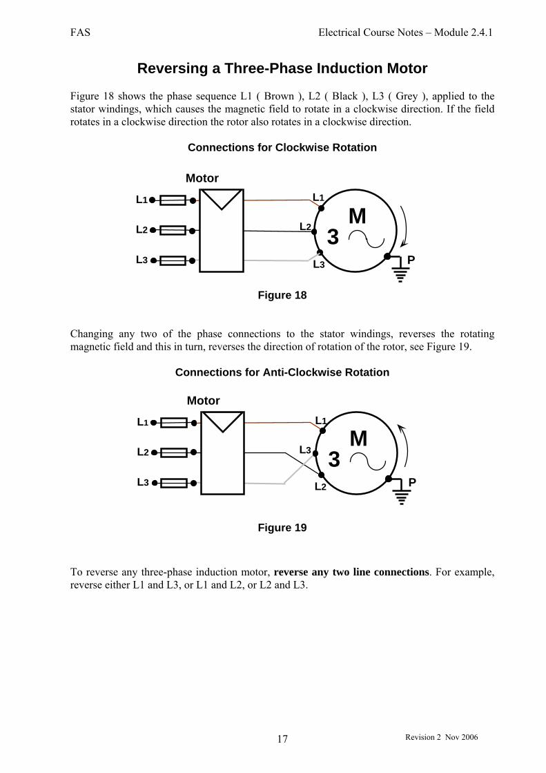
Reversing a Three-Phase Induction Motor Figure 18 shows the phase sequence L1 ( Brown ), L2 ( Black ), L3 ( Grey ), applied to the stator windings, which causes the magnetic field to rotate in a clockwise direction. If the field rotates in a clockwise direction the rotor also rotates in a clockwise direction.
Connections for Clockwise Rotation
Figure 18
Changing any two of the phase connections to the stator windings, reverses the rotating magnetic field and this in turn, reverses the direction of rotation of the rotor, see Figure 19.
Connections for Anti-Clockwise Rotation
Figure 19
To reverse any three-phase induction motor, reverse any two line connections. For example, reverse either L1 and L3, or L1 and L2, or L2 and L3.
P
L1
L2
L3
Motor
M3
L1
L2
L3
P
L1
L3
L2
Motor
M3
L1
L2
L3
FAS Electrical Course Notes – Module 2.4.1
Revision 2 Nov 2006 18
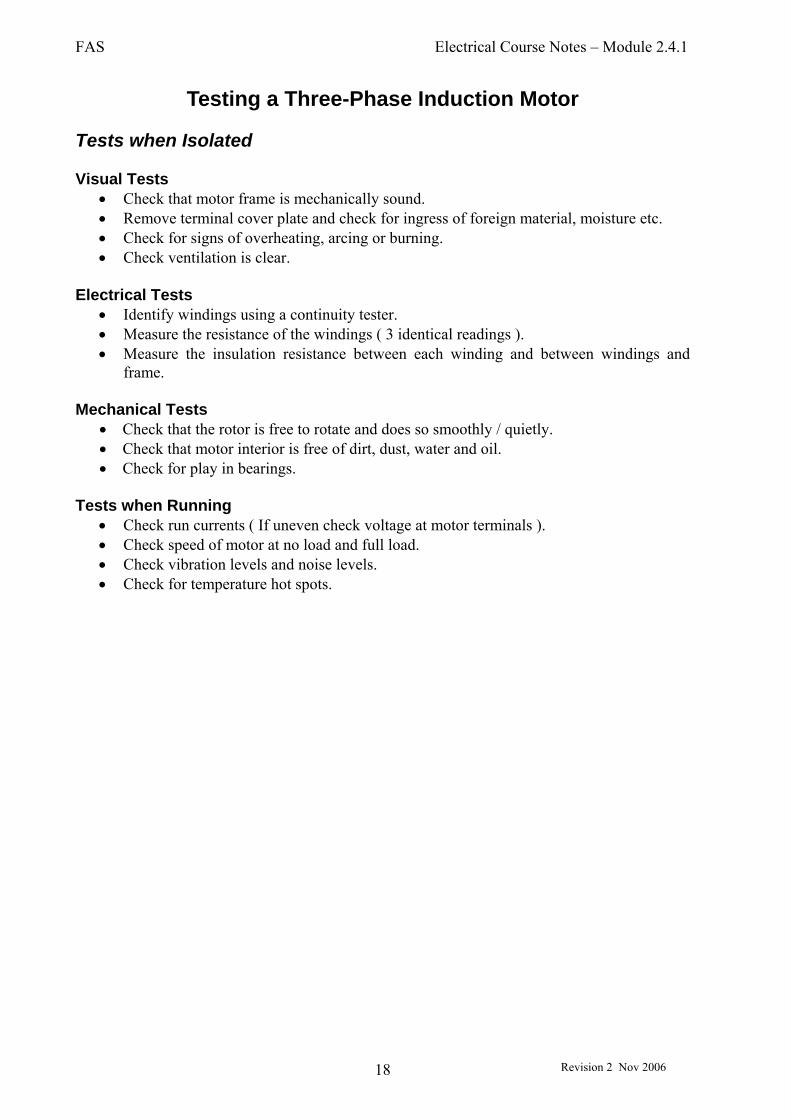
Testing a Three-Phase Induction Motor Tests when Isolated Visual Tests
• Check that motor frame is mechanically sound. • Remove terminal cover plate and check for ingress of foreign material, moisture etc. • Check for signs of overheating, arcing or burning. • Check ventilation is clear.
Electrical Tests
• Identify windings using a continuity tester. • Measure the resistance of the windings ( 3 identical readings ). • Measure the insulation resistance between each winding and between windings and
frame. Mechanical Tests
• Check that the rotor is free to rotate and does so smoothly / quietly. • Check that motor interior is free of dirt, dust, water and oil. • Check for play in bearings.
Tests when Running
• Check run currents ( If uneven check voltage at motor terminals ). • Check speed of motor at no load and full load. • Check vibration levels and noise levels. • Check for temperature hot spots.
FAS Electrical Course Notes – Module 2.4.1
Revision 2 Nov 2006 19
Testing of Three-Phase Stator Windings Resistance Test This test is carried out on an isolated motor, to check the resistance of the stator windings. It is necessary to make an accurate measurement, so a low reading ohmmeter or a high-resolution digital multimeter should be used. Step 1: Isolate the motor electrically, and if necessary, mechanically. Step 2: Identify the way the motor terminal block is connected. • Star connected. Make a careful note of how the three supply cables are connected so as
to avoid errors when re-connecting. Two links connect U2-V2-W2. Remove the links and the supply cables before carrying out the test. Disconnecting the cables ensures that there are no parallel paths via any control equipment, which would lead to false readings being obtained.
• Delta connected. Make a careful note of how the three supply cables are connected so as
to avoid errors when re-connecting. Three links connect U1 to W2, V1 to U2, W1 to V2; Remove the links and the supply cables before carrying out the test. Disconnecting the cables ensures that there are no parallel paths via any control equipment, which would lead to false readings being obtained.
• Star-Delta connected. Make a careful note of how the six supply cables are connected
so as to avoid errors when re-connecting. It is required that all conductors be disconnected from the terminal block during the test. Disconnecting the supply cables ensures that there are no parallel paths via any control equipment, which would lead to false readings being obtained.
Step 3: Identify the 3 stator windings - usually labelled U1-U2, V1-V2, and W1-W2. Step 4: Measure and record the resistance of each winding. If there is any appreciable difference between one winding and the other two, this indicates a fault condition. If one winding resistance is higher than the other two, this indicates that a high resistance fault is developing possibly due to a poor quality solder joint. An infinite resistance indicates an open circuit ( or break ) in the winding. If the resistance of one winding is lower than the other two, this indicates that the winding is becoming short-circuited. This is possibly due to an inter-turns short circuit on that winding. It is usually the result of the winding overheating, which damages the insulation ( shellac / varnish ), or because of mechanical damage. Both faults may necessitate having the motor rewound.
FAS Electrical Course Notes – Module 2.4.1
Revision 2 Nov 2006 20
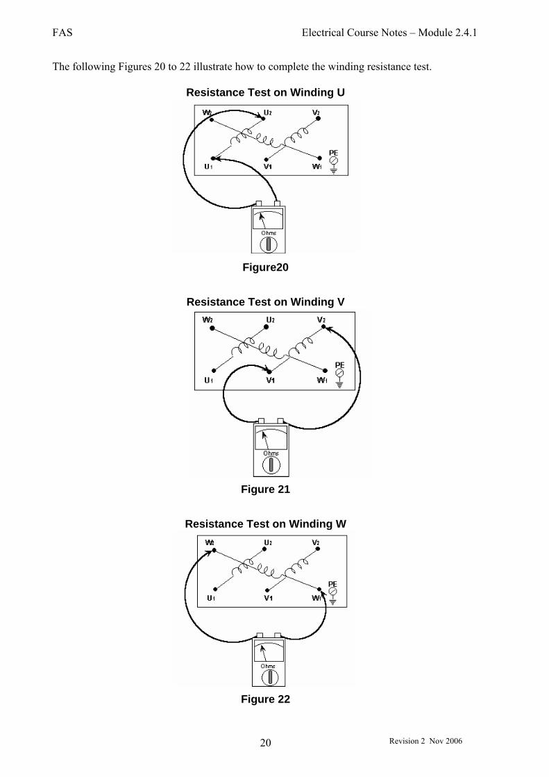
The following Figures 20 to 22 illustrate how to complete the winding resistance test.
Resistance Test on Winding U
Figure20
Resistance Test on Winding V
Figure 21
Resistance Test on Winding W
Figure 22

FAS Electrical Course Notes – Module 2.4.1
Revision 2 Nov 2006 21
Insulation Resistance Test This is a test carried out to determine the quality of the insulation between: • The windings and the motor frame • Between the individual windings Insulation Resistance Tests Between Windings and Frame Step 1: Isolate the motor electrically, and if necessary, mechanically. Step 2: Make a careful note of how the supply cables are connected so as to avoid errors
when re-connecting. Disconnect the supply cables from the motor terminal block to ensure that there are no parallel paths via the control equipment, which would lead to false low readings being obtained. Such disconnection of cables will also ensure that any electronic equipment in the circuit will be isolated before the test commences, as it may be damaged, by the Insulation Resistance Test, voltage.
Step 3: Measure the insulation resistance between the U winding and frame. Some
motor manufactures recommend a reading of not less than 10 MΩ however a reading of not less than 2 MΩ is generally accepted. See Figure 23.
U2 V2
V1 W1PE
Insulation ResistanceTester 500V
W2
U1
Figure 23
FAS Electrical Course Notes – Module 2.4.1
Revision 2 Nov 2006 22
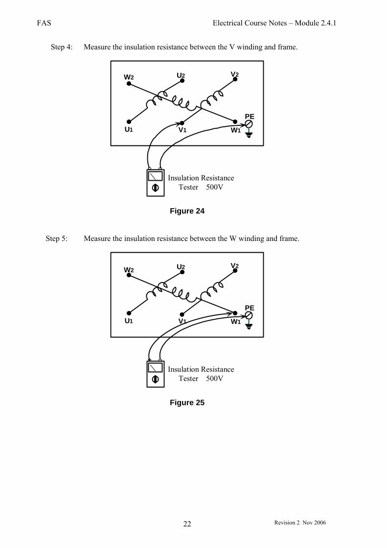
Step 4: Measure the insulation resistance between the V winding and frame.
U2 V2
V1 W1
PE
Insulation ResistanceTester 500V
W2
U1
Figure 24
Step 5: Measure the insulation resistance between the W winding and frame.
U2 V2
V1 W1
PE
Insulation ResistanceTester 500V
W2
U1
Figure 25
FAS Electrical Course Notes – Module 2.4.1
Revision 2 Nov 2006 23
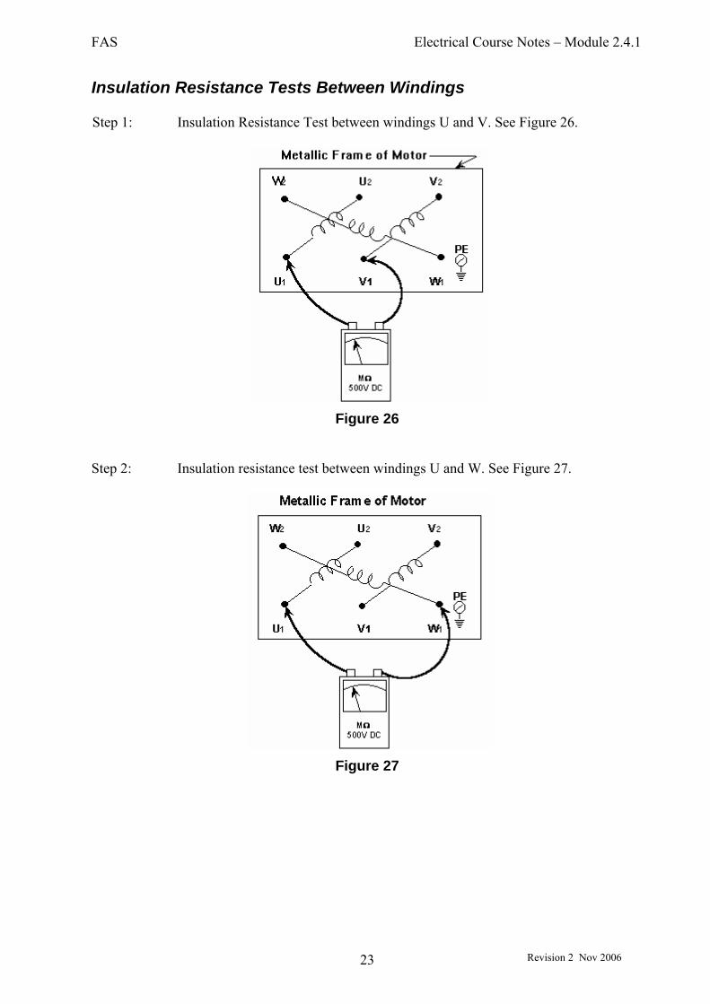
Insulation Resistance Tests Between Windings Step 1: Insulation Resistance Test between windings U and V. See Figure 26.
Figure 26
Step 2: Insulation resistance test between windings U and W. See Figure 27.
Figure 27
FAS Electrical Course Notes – Module 2.4.1
Revision 2 Nov 2006 24
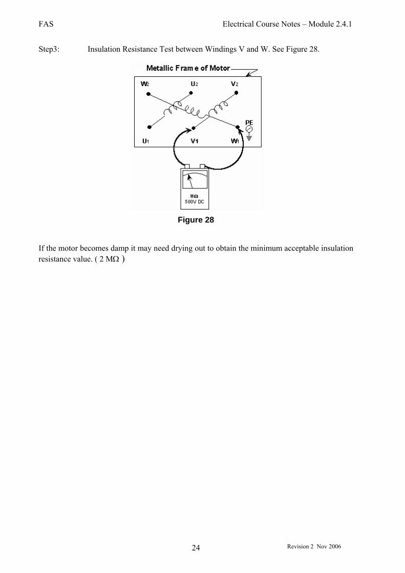
Step3: Insulation Resistance Test between Windings V and W. See Figure 28.
Figure 28
If the motor becomes damp it may need drying out to obtain the minimum acceptable insulation resistance value. ( 2 MΩ )
FAS Electrical Course Notes – Module 2.4.1
Revision 2 Nov 2006 25
Activity Each apprentice to perform the following electrical tests and observations on an isolated 3-phase induction motor and complete the attached test report sheet.
1. Makers Name.
2. Number of internal connections.
3. Motor rated voltage. ( Include any star or delta symbols
4. Motor full load current. as they appear on motor nameplate )
5. Determine from manufacturer’s nameplate the rotor speed.
6. Motor rated power in watts & HP (1 Horse Power (HP) = 746 watts).
7. Motor rated frequency.
8. Motor IP rating.
9. Should the motor be connected in star or delta?
10. Sketch the motor terminal box and show the three stator windings connected to their respective terminals.
11. Identify stator winding markings and insert on the report.
12. Carry out resistance tests of stator windings and record.
13. Carry out insulation resistance tests and record.
FAS Electrical Course Notes – Module 2.4.1
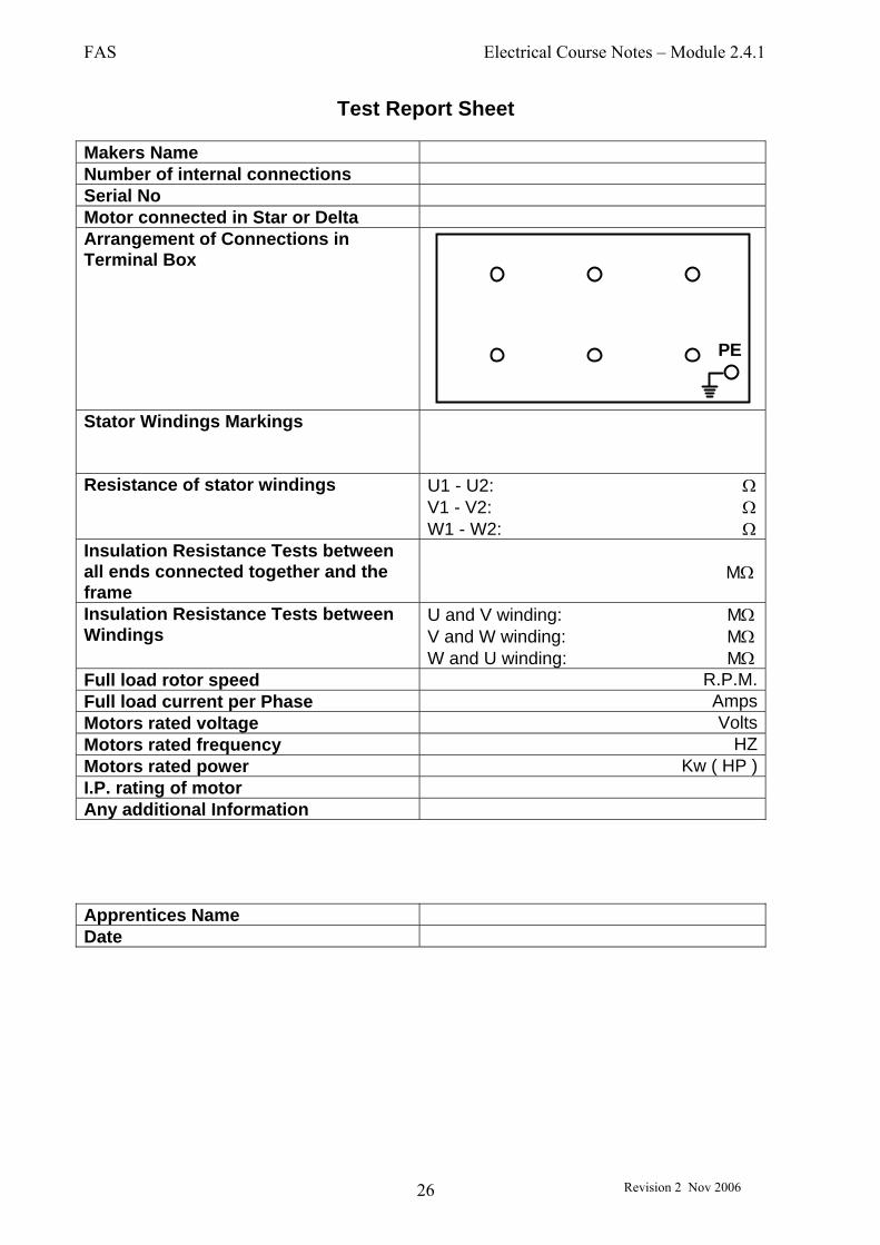
Revision 2 Nov 2006 26
Test Report Sheet Makers Name Number of internal connections Serial No Motor connected in Star or Delta Arrangement of Connections in Terminal Box
PE
Stator Windings Markings
Resistance of stator windings U1 - U2: ΩV1 - V2: ΩW1 - W2: Ω
Insulation Resistance Tests between all ends connected together and the frame
MΩ
Insulation Resistance Tests between Windings
U and V winding: MΩ V and W winding: MΩ W and U winding: MΩ
Full load rotor speed R.P.M.Full load current per Phase AmpsMotors rated voltage VoltsMotors rated frequency HZMotors rated power Kw ( HP )I.P. rating of motor Any additional Information Apprentices Name Date
FAS Electrical Course Notes – Module 2.4.1
Revision 2 Nov 2006 27
Methods of Starting Three Phase Induction Motors Every motor requires an efficient method of starting and stopping, which takes into account the starting current of the motor. There are several methods employed for starting three-phase induction motors. • Direct-On-Line Starting • Resistance Starting • Reactance Starting • Auto-transformer Starting • Star-Delta Starting • Part-Winding Starting • Solid State Starting During this course we will only consider the Direct-On-Line ( D.O.L ) method of starting. This is the simplest and most commonly used method. Direct-On-Line Starting ( D.O.L. ) Unlike the other starting methods listed above, the D.O.L. starter does nothing to limit the starting current of the motor. This starting current may be as high as six to seven times the Full Load Current ( FLC ). This can cause supply difficulties such as dimming and flickering of lights and disturbances to other apparatus due to voltage drop. The limit to the size of motor, which may be started by this method, is almost entirely dependant upon the conditions of the supply.
FAS Electrical Course Notes – Module 2.4.1
Revision 2 Nov 2006 28
Summary • The three-phase squirrel cage induction motor is the most commonly encountered motor. • A three-phase supply is capable of producing a three-phase rotating magnetic field in the
stator. • The direct-on-line ( D.O.L ) method of starting is the most extensively used starting method
but does not provide initial current limitation control. • Changing any two of the phase connections to the stator windings reverses the phase
sequence and this in turn reverses the direction of rotation of the rotor. • The three-phase squirrel cage induction motor is cheap, reliable, quieter, smoother running
and requires less maintenance than single-phase motors.
FAS Electrical Course Notes – Module 2.4.1
Revision 2 Nov 2006 29
Single Phase Induction Motors Introduction When a single-phase supply is connected to a single stator winding it provides an alternating rather than a rotating magnetic field and the rotor will not turn. However, single-phase motors will run successfully provided that an initial start is given to the rotor. They will run in either direction depending on the direction of the initial start. This initial start is produced by providing an artificial phase, which simulates a two-phase supply. In order to create this artificial phase, single-phase induction motors are manufactured with two separate windings. These windings are connected in parallel with each other during starting. One winding is called the Main Winding ( or Run Winding ), while the other winding is called the Auxiliary Winding ( or Start Winding ). The main winding is always left in circuit, but the auxiliary winding may be disconnected once the motor has started. There are four different types of single-phase induction motor. The particular name given to each of these relates to its starting arrangement, and is as follows.
1. Split Phase Motor. 2. Capacitor Start Motor. 3. Capacitor Start and Run Motor. 4. Capacitor Start Capacitor Run Motor.
They are in common use, particularly in domestic, agricultural and commercial spheres. Single-phase induction motor cannot compete with the performance or efficiency of three-phase induction motors. They are more troublesome, mainly on account of the ancillary starting equipment required. They are also physically larger than equally rated three-phase motors.
FAS Electrical Course Notes – Module 2.4.1
Revision 2 Nov 2006 30
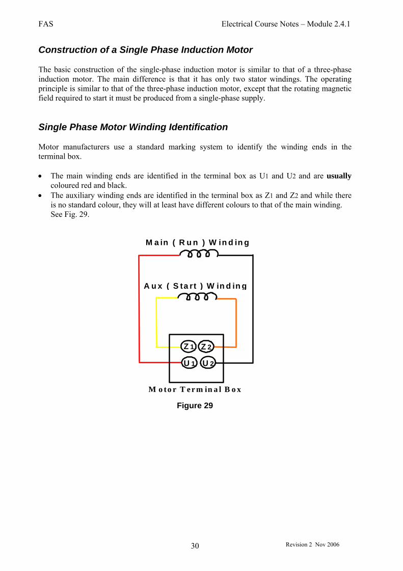
Construction of a Single Phase Induction Motor The basic construction of the single-phase induction motor is similar to that of a three-phase induction motor. The main difference is that it has only two stator windings. The operating principle is similar to that of the three-phase induction motor, except that the rotating magnetic field required to start it must be produced from a single-phase supply. Single Phase Motor Winding Identification Motor manufacturers use a standard marking system to identify the winding ends in the terminal box. • The main winding ends are identified in the terminal box as U1 and U2 and are usually
coloured red and black. • The auxiliary winding ends are identified in the terminal box as Z1 and Z2 and while there
is no standard colour, they will at least have different colours to that of the main winding. See Fig. 29.
M o to r T e r m in a l B o x
M a in ( R u n ) W in d in g
A u x ( S ta rt ) W in d in g
Z 1 Z 2
U 1 U 2
Figure 29
FAS Electrical Course Notes – Module 2.4.1
Revision 2 Nov 2006 31
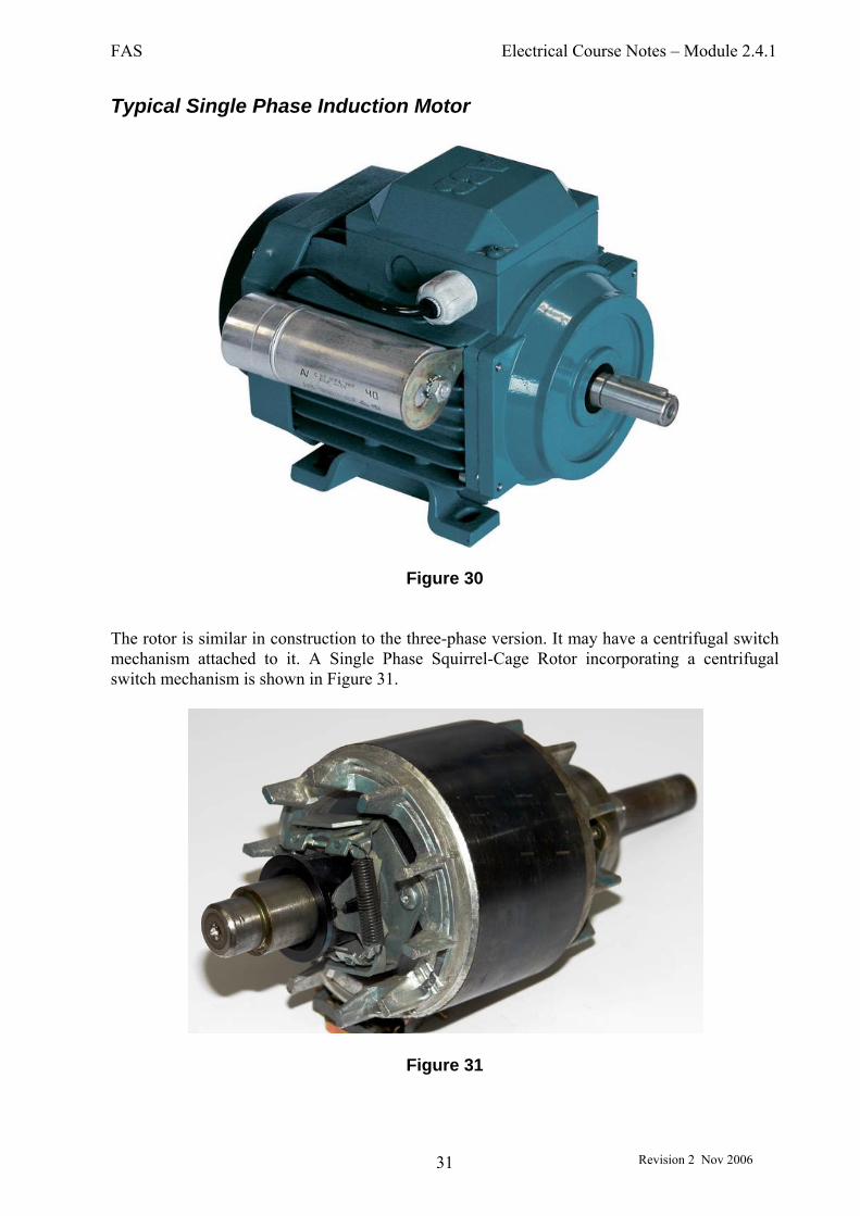
Typical Single Phase Induction Motor
Figure 30 The rotor is similar in construction to the three-phase version. It may have a centrifugal switch mechanism attached to it. A Single Phase Squirrel-Cage Rotor incorporating a centrifugal switch mechanism is shown in Figure 31.
Figure 31
FAS Electrical Course Notes – Module 2.4.1
Revision 2 Nov 2006 32
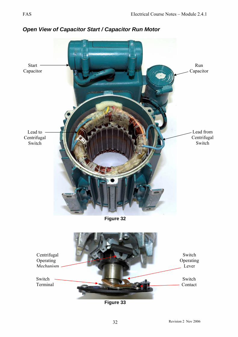
Open View of Capacitor Start / Capacitor Run Motor
Figure 32
Figure 33
Start Capacitor
Run Capacitor
Lead to Centrifugal
Switch
Lead from Centrifugal
Switch
CentrifugalOperating Mechanism
Switch Operating
Lever
Switch Contact
Switch Terminal
FAS Electrical Course Notes – Module 2.4.1
Revision 2 Nov 2006 33
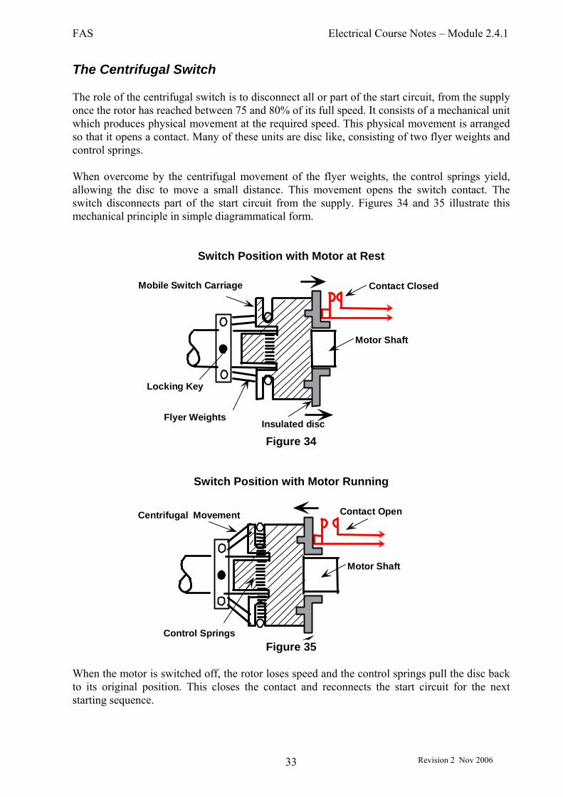
The Centrifugal Switch The role of the centrifugal switch is to disconnect all or part of the start circuit, from the supply once the rotor has reached between 75 and 80% of its full speed. It consists of a mechanical unit which produces physical movement at the required speed. This physical movement is arranged so that it opens a contact. Many of these units are disc like, consisting of two flyer weights and control springs. When overcome by the centrifugal movement of the flyer weights, the control springs yield, allowing the disc to move a small distance. This movement opens the switch contact. The switch disconnects part of the start circuit from the supply. Figures 34 and 35 illustrate this mechanical principle in simple diagrammatical form.
Switch Position with Motor at Rest
Contact Closed
Motor Shaft
Insulated disc
Locking Key
Mobile Switch Carriage
Flyer Weights
Figure 34
Switch Position with Motor Running
Contact Open
Motor Shaft
Control Springs
Centrifugal Movement
Figure 35
When the motor is switched off, the rotor loses speed and the control springs pull the disc back to its original position. This closes the contact and reconnects the start circuit for the next starting sequence.
FAS Electrical Course Notes – Module 2.4.1
Revision 2 Nov 2006 34
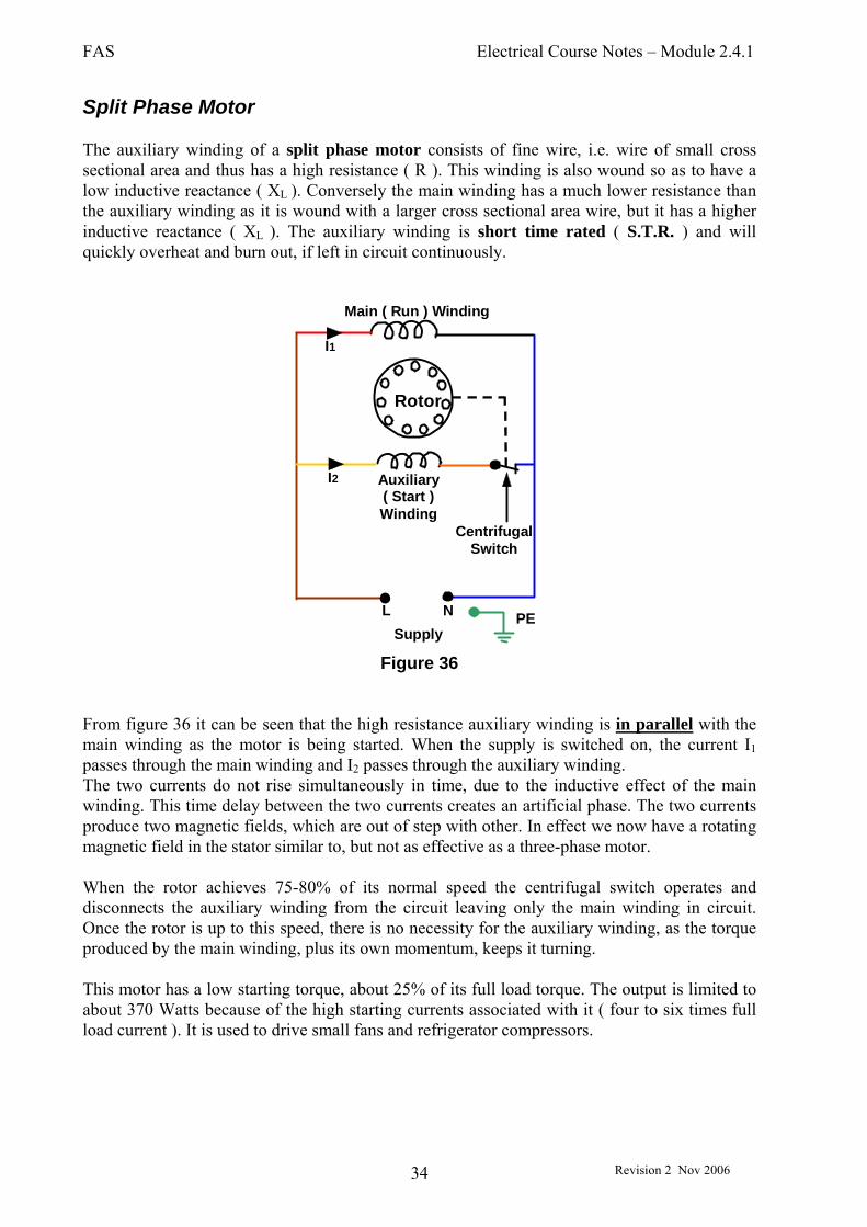
Split Phase Motor The auxiliary winding of a split phase motor consists of fine wire, i.e. wire of small cross sectional area and thus has a high resistance ( R ). This winding is also wound so as to have a low inductive reactance ( XL ). Conversely the main winding has a much lower resistance than the auxiliary winding as it is wound with a larger cross sectional area wire, but it has a higher inductive reactance ( XL ). The auxiliary winding is short time rated ( S.T.R. ) and will quickly overheat and burn out, if left in circuit continuously.
CentrifugalSwitch
Main ( Run ) Winding
Auxiliary( Start ) Winding
I1
I2
L N PE Supply
Rotor
Figure 36
From figure 36 it can be seen that the high resistance auxiliary winding is in parallel with the main winding as the motor is being started. When the supply is switched on, the current I1 passes through the main winding and I2 passes through the auxiliary winding. The two currents do not rise simultaneously in time, due to the inductive effect of the main winding. This time delay between the two currents creates an artificial phase. The two currents produce two magnetic fields, which are out of step with other. In effect we now have a rotating magnetic field in the stator similar to, but not as effective as a three-phase motor. When the rotor achieves 75-80% of its normal speed the centrifugal switch operates and disconnects the auxiliary winding from the circuit leaving only the main winding in circuit. Once the rotor is up to this speed, there is no necessity for the auxiliary winding, as the torque produced by the main winding, plus its own momentum, keeps it turning. This motor has a low starting torque, about 25% of its full load torque. The output is limited to about 370 Watts because of the high starting currents associated with it ( four to six times full load current ). It is used to drive small fans and refrigerator compressors.
FAS Electrical Course Notes – Module 2.4.1
Revision 2 Nov 2006 35
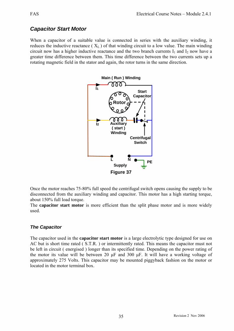
Capacitor Start Motor When a capacitor of a suitable value is connected in series with the auxiliary winding, it reduces the inductive reactance ( XL ) of that winding circuit to a low value. The main winding circuit now has a higher inductive reactance and the two branch currents I1 and I2 now have a greater time difference between them. This time difference between the two currents sets up a rotating magnetic field in the stator and again, the rotor turns in the same direction.
CentrifugalSwitch
Main ( Run ) Winding
Auxiliary( start ) Winding
I1
I2
L N PE Supply
Rotor
StartCapacitor
Figure 37
Once the motor reaches 75-80% full speed the centrifugal switch opens causing the supply to be disconnected from the auxiliary winding and capacitor. This motor has a high starting torque, about 150% full load torque. The capacitor start motor is more efficient than the split phase motor and is more widely used. The Capacitor The capacitor used in the capacitor start motor is a large electrolytic type designed for use on AC but is short time rated ( S.T.R. ) or intermittently rated. This means the capacitor must not be left in circuit ( energised ) longer than its specified time. Depending on the power rating of the motor its value will be between 20 μF and 300 μF. It will have a working voltage of approximately 275 Volts. This capacitor may be mounted piggyback fashion on the motor or located in the motor terminal box.
FAS Electrical Course Notes – Module 2.4.1
Revision 2 Nov 2006 36
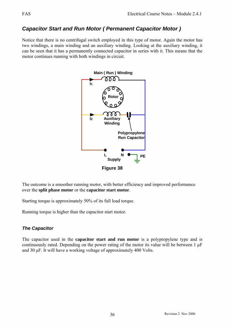
Capacitor Start and Run Motor ( Permanent Capacitor Motor ) Notice that there is no centrifugal switch employed in this type of motor. Again the motor has two windings, a main winding and an auxiliary winding. Looking at the auxiliary winding, it can be seen that it has a permanently connected capacitor in series with it. This means that the motor continues running with both windings in circuit.
Main ( Run ) Winding
AuxiliaryWinding
I1
I2
L N PE Supply
Rotor
PolypropyleneRun Capacitor
Figure 38
The outcome is a smoother running motor, with better efficiency and improved performance over the split phase motor or the capacitor start motor. Starting torque is approximately 50% of its full load torque. Running torque is higher than the capacitor start motor. The Capacitor The capacitor used in the capacitor start and run motor is a polypropylene type and is continuously rated. Depending on the power rating of the motor its value will be between 1 μF and 30 μF. It will have a working voltage of approximately 400 Volts.
FAS Electrical Course Notes – Module 2.4.1
Revision 2 Nov 2006 37
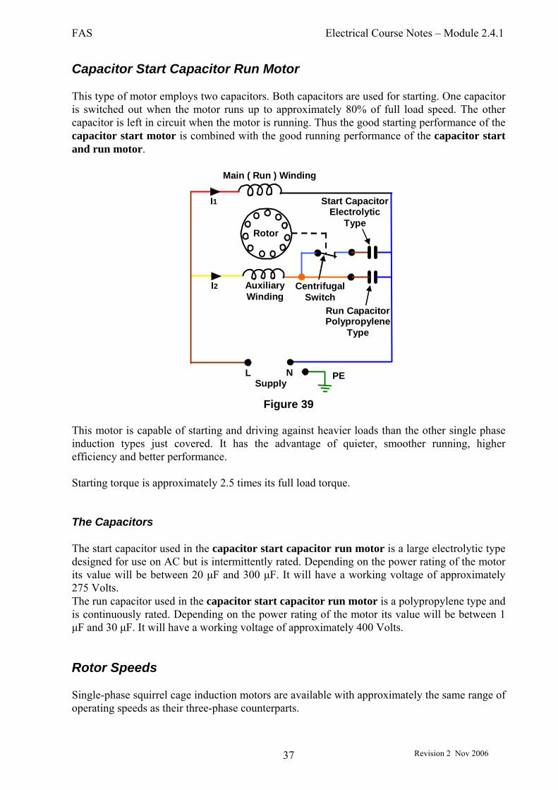
Capacitor Start Capacitor Run Motor This type of motor employs two capacitors. Both capacitors are used for starting. One capacitor is switched out when the motor runs up to approximately 80% of full load speed. The other capacitor is left in circuit when the motor is running. Thus the good starting performance of the capacitor start motor is combined with the good running performance of the capacitor start and run motor.
I1
Rotor
Main ( Run ) Winding
AuxiliaryWinding
L N PE Supply
Start CapacitorElectrolytic
Type
Run CapacitorPolypropylene
Type
CentrifugalSwitch
I2
Figure 39
This motor is capable of starting and driving against heavier loads than the other single phase induction types just covered. It has the advantage of quieter, smoother running, higher efficiency and better performance. Starting torque is approximately 2.5 times its full load torque. The Capacitors The start capacitor used in the capacitor start capacitor run motor is a large electrolytic type designed for use on AC but is intermittently rated. Depending on the power rating of the motor its value will be between 20 μF and 300 μF. It will have a working voltage of approximately 275 Volts. The run capacitor used in the capacitor start capacitor run motor is a polypropylene type and is continuously rated. Depending on the power rating of the motor its value will be between 1 μF and 30 μF. It will have a working voltage of approximately 400 Volts. Rotor Speeds Single-phase squirrel cage induction motors are available with approximately the same range of operating speeds as their three-phase counterparts.
FAS Electrical Course Notes – Module 2.4.1
Revision 2 Nov 2006 38
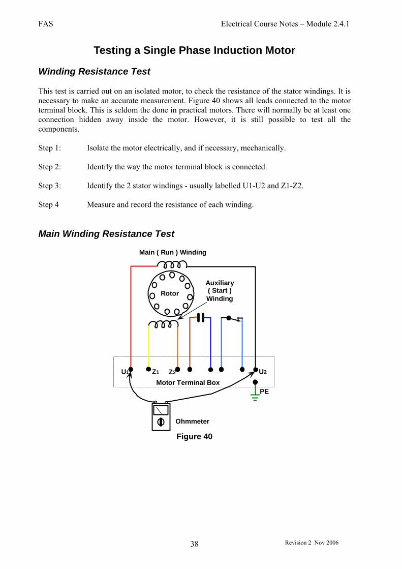
Testing a Single Phase Induction Motor Winding Resistance Test This test is carried out on an isolated motor, to check the resistance of the stator windings. It is necessary to make an accurate measurement. Figure 40 shows all leads connected to the motor terminal block. This is seldom the done in practical motors. There will normally be at least one connection hidden away inside the motor. However, it is still possible to test all the components. Step 1: Isolate the motor electrically, and if necessary, mechanically. Step 2: Identify the way the motor terminal block is connected. Step 3: Identify the 2 stator windings - usually labelled U1-U2 and Z1-Z2. Step 4 Measure and record the resistance of each winding. Main Winding Resistance Test
Main ( Run ) Winding
Auxiliary( Start ) Winding
U1
Rotor
Z1 Z2 U2
PE Motor Terminal Box
Ohmmeter
Figure 40
FAS Electrical Course Notes – Module 2.4.1
Revision 2 Nov 2006 39
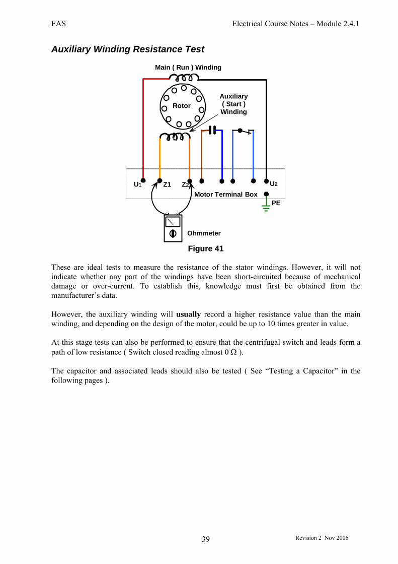
Auxiliary Winding Resistance Test
Main ( Run ) Winding
Auxiliary( Start ) Winding
U1
Rotor
Z1 Z2 U2
PEMotor Terminal Box
Ohmmeter
Figure 41 These are ideal tests to measure the resistance of the stator windings. However, it will not indicate whether any part of the windings have been short-circuited because of mechanical damage or over-current. To establish this, knowledge must first be obtained from the manufacturer’s data. However, the auxiliary winding will usually record a higher resistance value than the main winding, and depending on the design of the motor, could be up to 10 times greater in value. At this stage tests can also be performed to ensure that the centrifugal switch and leads form a path of low resistance ( Switch closed reading almost 0 Ω ). The capacitor and associated leads should also be tested ( See “Testing a Capacitor” in the following pages ).
FAS Electrical Course Notes – Module 2.4.1
Revision 2 Nov 2006 40
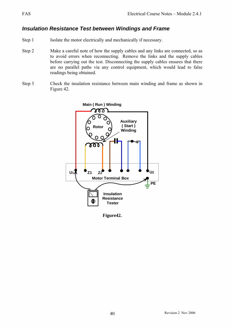
Insulation Resistance Test between Windings and Frame Step 1 Isolate the motor electrically and mechanically if necessary. Step 2 Make a careful note of how the supply cables and any links are connected, so as
to avoid errors when reconnecting. Remove the links and the supply cables before carrying out the test. Disconnecting the supply cables ensures that there are no parallel paths via any control equipment, which would lead to false readings being obtained.
Step 3 Check the insulation resistance between main winding and frame as shown in
Figure 42.
Main ( Run ) Winding
Auxiliary( Start ) Winding
U1
Rotor
Z1 Z2 U2
PEMotor Terminal Box
InsulationResistance
Tester
Figure42.
FAS Electrical Course Notes – Module 2.4.1
Revision 2 Nov 2006 41
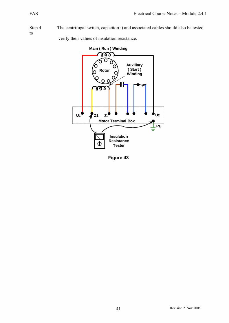
Step 4 The centrifugal switch, capacitor(s) and associated cables should also be tested to
verify their values of insulation resistance.
Main ( Run ) Winding
Auxiliary( Start ) Winding
U1
Rotor
Z1 Z2 U2
PEMotor Terminal Box
InsulationResistance
Tester
Figure 43
FAS Electrical Course Notes – Module 2.4.1
Revision 2 Nov 2006 42
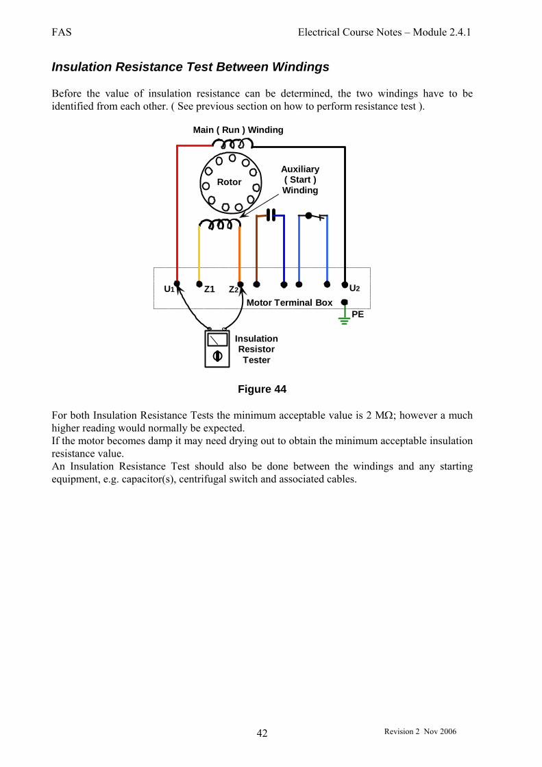
Insulation Resistance Test Between Windings Before the value of insulation resistance can be determined, the two windings have to be identified from each other. ( See previous section on how to perform resistance test ).
Main ( Run ) Winding
Auxiliary( Start ) Winding
U1
Rotor
Z1 Z2 U2
PEMotor Terminal Box
InsulationResistor Tester
Figure 44
For both Insulation Resistance Tests the minimum acceptable value is 2 MΩ; however a much higher reading would normally be expected. If the motor becomes damp it may need drying out to obtain the minimum acceptable insulation resistance value. An Insulation Resistance Test should also be done between the windings and any starting equipment, e.g. capacitor(s), centrifugal switch and associated cables.
FAS Electrical Course Notes – Module 2.4.1
Revision 2 Nov 2006 43
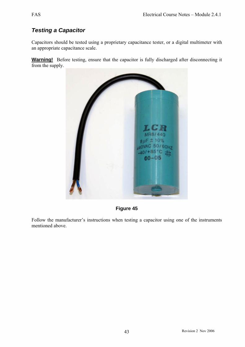
Testing a Capacitor Capacitors should be tested using a proprietary capacitance tester, or a digital multimeter with an appropriate capacitance scale. Warning! Before testing, ensure that the capacitor is fully discharged after disconnecting it from the supply.
Figure 45 Follow the manufacturer’s instructions when testing a capacitor using one of the instruments mentioned above.
FAS Electrical Course Notes – Module 2.4.1
Revision 2 Nov 2006 44
Testing a Centrifugal Switch Check the mechanism of the centrifugal switch, ensuring that when the weights are moved by hand, the contact opens, and when the flier weights are released, the contact closes. The switch contact surfaces may be cleaned with fine emery paper if necessary. Also check the lead connections on the fixed back plate. Problems ensuing from centrifugal switching devices Practical difficulties may appear in many different ways, frequently resulting in the motor not being able to start or to change from one running mode to another. Listed are two common conditions, which can affect the automatic switching sequence. 1. Switch Permanently Closed
This often results from a problem such as a seized switch assembly, arc welded switch contact. Should this occur the start circuit will not be disconnected when the motor starts. This will result in failure of the start capacitor or start winding, unless the overload protection operates or the supply is manually disconnected. To rectify: Repair or change the switch assembly for a correct replacement Carry out resistance and insulation resistance tests on both windings. Check, and if necessary replace the capacitor. It may be faulty as a result of the
defective centrifugal switch contact or mechanism.
Switch Permanently Open
This often results from a control spring problem ( broken spring ), a seized or sticking switch assembly, worn assembly parts or damaged contacts. A motor falling casualty to this problem will not start unaided. It will produce a “50 cycle hum”. The result will be failure of the main winding unless the overload protection operates or the supply is manually disconnected.
To rectify
Repair or change the switch assembly for a correct replacement. Carry out resistance and insulation resistance tests on the main winding.
FAS Electrical Course Notes – Module 2.4.1
Revision 2 Nov 2006 45
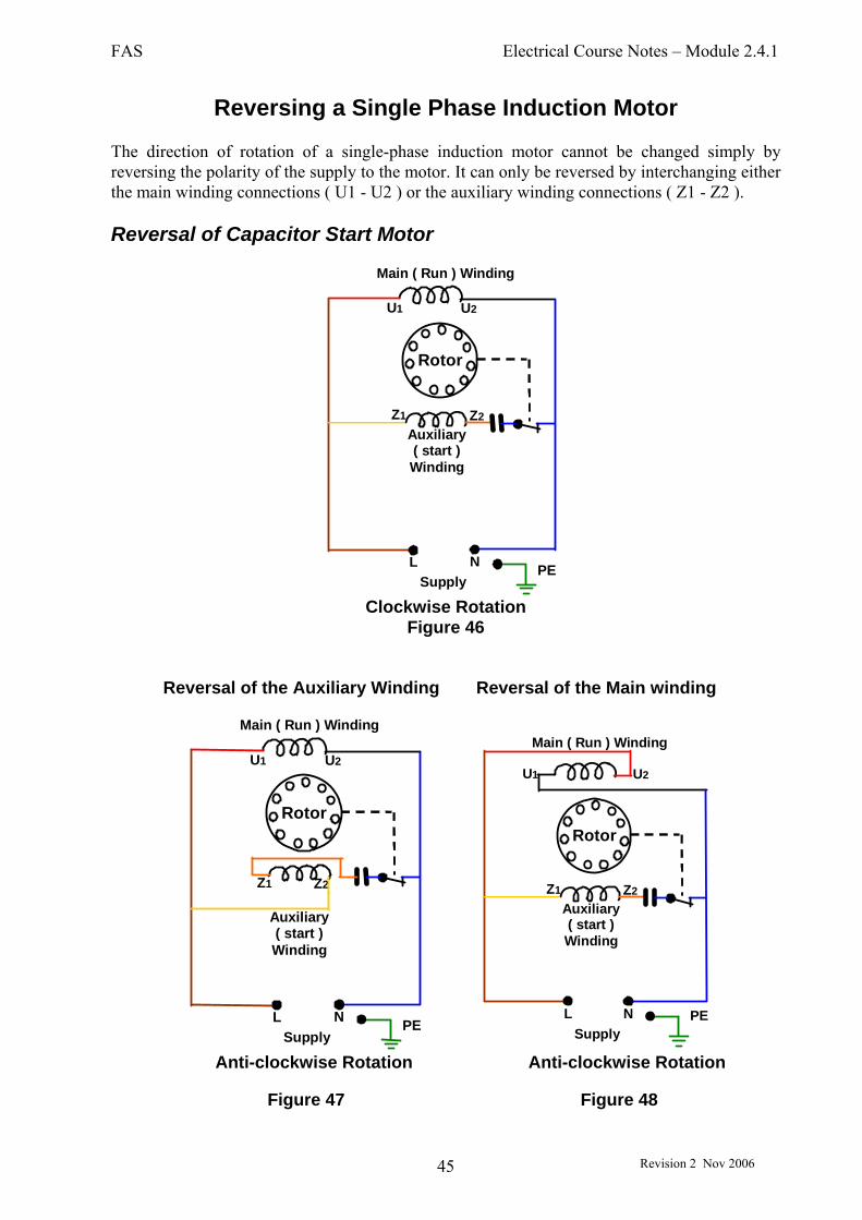
Reversing a Single Phase Induction Motor The direction of rotation of a single-phase induction motor cannot be changed simply by reversing the polarity of the supply to the motor. It can only be reversed by interchanging either the main winding connections ( U1 - U2 ) or the auxiliary winding connections ( Z1 - Z2 ). Reversal of Capacitor Start Motor
Z2
Main ( Run ) Winding
Auxiliary( start ) Winding
U1
Z1
L N PE Supply
Rotor
U2
Clockwise Rotation
Figure 46
Reversal of the Auxiliary Winding Reversal of the Main winding
Z2
Main ( Run ) Winding
Auxiliary ( start ) Winding
U1
Z1
L N PE Supply
Rotor
U2
Z2
Main ( Run ) Winding
Auxiliary ( start ) Winding
U1
Z1
L N PE Supply
Rotor
U2
Anti-clockwise Rotation Anti-clockwise Rotation
Figure 47 Figure 48
FAS Electrical Course Notes – Module 2.4.1
Revision 2 Nov 2006 46
Methods of Starting Single Phase Induction Motors Single phase motors of 7.5 kW output are available. Motors up to 4 kW are in common use, particularly in agricultural premises. The starting current of these motors is four to six times their full load current. This may cause supply difficulties such as dimming and flickering of lights and other line disturbances. Consultation with the electricity supply authority is advisable in such circumstances prior to installation of large single-phase motors. There are two methods employed for starting single-phase induction motors. • Direct-On-Line • Series Parallel The method of starting usually used is Direct On Line. This method does nothing to reduce the starting current of the motor. The limit to the size of motor, which may be started by this method, is almost entirely dependant upon the conditions of the supply. During this course we only consider the ( D.O.L ) method of starting. This is the simplest and most commonly used method.
FAS Electrical Course Notes – Module 2.4.1
Revision 2 Nov 2006 47
Summary
• Single phase induction motors consist of: 1. A standard cage rotor. 2. A stator usually consisting of two windings.
• There are two main starting methods or arrangements for single phase induction motors:
1. Inductive Winding. 2. Capacitive Winding.
• The split phase induction motor is the name given to a particular type of motor where a
rotating magnetic field is produced by having the auxiliary winding of a higher inductance or resistance than the main winding.
• When a capacitor(s) of a suitable value is connected in series with the auxiliary
winding, a rotating magnetic field is established. The names of the capacitor motors are derived from the way the capacitor(s) are connected to the auxiliary winding.
• The supply is generally switched directly onto single-phase motors.
• The direction of rotation of a single phase induction motor may be reversed by
interchanging either the auxiliary winding connections ( Z1 - Z2 ) or the main winding connections ( U1- U2 ).
Activity Each apprentice is to perform the following electrical tests and observations on an Isolated Single Phase Induction Motor. Then complete the attached report sheet.
• Makers name. • Serial no. • Starting arrangement. e.g. “Capacitor Start” • Arrangement of connections in terminal box. • Stator windings markings. • Resistance of stator windings. • Insulation resistance tests. • Capacitor tests. • Centrifugal switch tests. • Full load rotor speed. • Full load current. • Motor rated voltage. • Motor rated frequency. • Motor rated output power. • I.P. Rating. • Any additional information.

FAS Electrical Course Notes – Module 2.4.1
Revision 2 Nov 2006 48
Report Sheet Makers Name Serial No Starting Arrangement Arrangement of Connections in Terminal Box
DE NDE
PE
Stator Winding Markings Resistance of Stator Windings Z1 - Z2 ΩU1 - U2 ΩInsulation Resistance Tests between all winding ends connected together and the frame
MΩ
Insulation Resistance Tests between main and auxiliary Windings
MΩ
Start Capacitor – type Capacitance Value µFVoltage Rating VoltsRun Capacitor type - (if fitted) Capacitance Value µFVoltage Rating VoltsCapacitor Test: Using a proprietary capacitance tester
FAIL / GOOD
Centrifugal Switch: Electrical Resistance across Switch Contact
Ω
Full Load Rotor Speed R.P.M.Full Load Current AmpsMotors Rated Voltage VoltsMotors Rated Frequency HzMotors Rated Output Power kWI.P. Rating Apprentice Name: Date: