trademarks - | channelproreviews · pdf fileother names used in this publication may be...
TRANSCRIPT

Mainboard User’s Manual
This publication, including all photographs, illustrations andsoftware, is protected under international copyright laws, with allrights reserved. Neither this manual, nor any of the materialcontained herein, may be reproduced without written consent of theauthor.The information in this document is subject to change withoutnotice. The manufacturer makes no representations or warrantieswith respect to the contents hereof and specifically disclaims anyimplied warranties of merchantability or fitness for any particularpurpose. Further, the manufacturer reserves the right to revise thispublication and to make changes from time to time in the contenthereof without obligation of the manufacturer to notify any personof such revision or changes.
TrademarksIBM, VGA, and PS/2 are registered trademarks of InternationalBusiness Machines.AMD and Duron are registered trademarks of Advanced MicroDevices Inc.Microsoft, MS-DOS and Windows 98/ME/NT/2000/XP areregistered trademarks of Microsoft Corporation.PC-cillin is a trademark of Trend Micro Inc.AMI is a trademark of Award Software Inc.A3D is a registered trademark of Aureal Inc.MediaRing Talk is a registered trademark of MediaRing Inc.3Deep is a registered trademark of E-Color Inc.Other names used in this publication may be trademarks and areacknowledged.
Copyright © 2002All Rights ReservedM810 Series, V7.1F
S73X/July 2002

Mainboard User’s Manual
II
Notice:Owing to Microsoft’s certifying schedule is various to everysupplier, we might have some drivers not certified yet byMicrosoft. Therefore, it might happen under Windows XP that adialogue box (shown as below) pop out warning you thissoftware has not passed Windows Logo testing to verify itscompatibility with Windows XP. Please rest assured that our RDdepartment has already tested and verified these drivers. Justclick the “Continue Anyway” button and go ahead theinstallation.

Mainboard User’s Manual
III
Table of Contents
Chapter 1: Introduction....................................................................1Key Features............................................................................2Package Contents.....................................................................5Static Electricity Precautions...................................................6Pre-Installation Inspection.......................................................6
Chapter 2: Mainboard Installation...................................................7Mainboard Components ..........................................................8I/O Ports...................................................................................9Install Memory ........................................................................9Setting Jumper Switches........................................................10Install the Mainboard.............................................................11Optional Extension Brackets .................................................12Install Other Devices .............................................................14Expansion Slots .....................................................................17
Chapter 3: BIOS Setup Utility.......................................................19Introduction ...........................................................................19Running the Setup Utility ......................................................20Standard CMOS Setup Page..................................................21Advanced Setup Page ............................................................22Power Management Setup Page ............................................23PCI / Plug and Play Setup Page.............................................25Load Optimal Settings ...........................................................25Load Best Performance Settings............................................26Features Setup Page...............................................................26CPU PnP Setup Page .............................................................28Hardware Monitor Page.........................................................29Change Password...................................................................29Exit ........................................................................................30
Chapter 4: Software & Applications .............................................31Introduction ...........................................................................31Installing Support Software ...................................................32Bundled Software Installation ...............................................34
Mainboard User’s Manual
IV
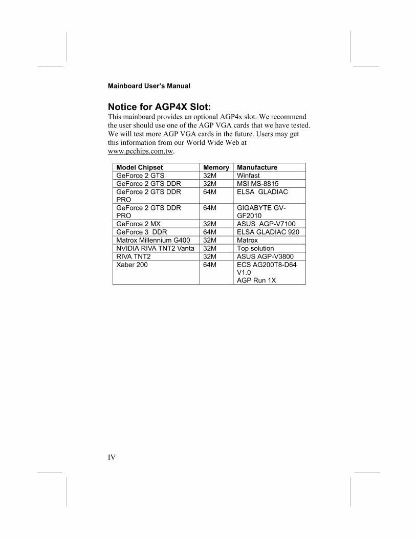
Notice for AGP4X Slot:This mainboard provides an optional AGP4x slot. We recommendthe user should use one of the AGP VGA cards that we have tested.We will test more AGP VGA cards in the future. Users may getthis information from our World Wide Web atwww.pcchips.com.tw.
Model Chipset Memory ManufactureGeForce 2 GTS 32M WinfastGeForce 2 GTS DDR 32M MSI MS-8815GeForce 2 GTS DDRPRO
64M ELSA GLADIAC
GeForce 2 GTS DDRPRO
64M GIGABYTE GV-GF2010
GeForce 2 MX 32M ASUS AGP-V7100GeForce 3 DDR 64M ELSA GLADIAC 920Matrox Millennium G400 32M MatroxNVIDIA RIVA TNT2 Vanta 32M Top solutionRIVA TNT2 32M ASUS AGP-V3800Xaber 200 64M ECS AG200T8-D64
V1.0AGP Run 1X

1: Introduction
1
Chapter 1Introduction
This mainboard has an AMD Duron Processor. This mainboarduses the SiS730S chipset that integrates a 128-bit AGP GraphicsAccelerator, and provides an optional 2X/4X AGP slot for highlygraphics display, the CPU Plug & Play through firmware, UltraDMA 33/66/100 function. The mainboard has a built-in AC’974Ch Codec, provides an AMR (Audio Modem Riser) slot tosupport Audio and Modem application, and has a built-in10BaseT/100BaseTX Network Interface. In addition, themainboard has an extended set of ATX I/O Ports including PS/2keyboard and mouse ports, two USB ports, one LAN port, oneparallel port, one serial port and one VGA port. Connecting theExtended USB Module to the mainborad makes two extra USBports.
This mainboard has all the features you need to develop a powerfulmultimedia workstation that is network ready. The board is MicroATX size and has power connectors for an ATX power supply.

Mainboard User’s Manual
2
Key FeaturesThe key features of this mainboard include:
CPU Type♦ Supports AMD Duron processor
Memory Support♦ Two DIMM slots for 168-pin SDRAM memory modules♦ Maximum installed memory is 2 x 512MB = 1GB
Expansion Slots♦ One AMR slot for a special audio/modem riser card♦ One optional AGP4X slot for AGP 2.0-cpmpliant interface♦ Two 32-bit PCI slots for PCI 2.2-compliant bus interface.
Onboard IDE channels♦ Primary and Secondary PCI IDE channels♦ Support for PIO (programmable input/output) modes♦ Support for Multiword DMA modes♦ Support for Bus Mastering and Ultra DMA 33/66/100
modes
Power Supply and Power Management♦ ATX power supply connector♦ ACPI and previous PMU support, suspend switch,
keyboard power on/off♦ Supports Wake on Modem, Wake on LAN and Wake on
Alarm

1: Introduction
3
Built-in Graphics System♦ Onboard 128-bit 2D/3D 100MHz Host interface AGP
Graphics Accelerator Complies with AGP V2.0♦ Shared memory architecture allows a maximum of 64 MB
main memory to act as frame buffer♦ Supports high resolutions up to 1920x1440 Hi-colors, up to
2048x2048 Texture size and Virtual screen up to4096x4096
♦ Supports hardware DVD Accelerator
AC’97 Audio Codec: VT1612A♦ Compliant with AC’97 2.1 specification♦ Three Audio Jacks – Line-Out, Line-In and Microphone-In♦ Sound Blaster, Sound Blaster Pro Compatible♦ Digital I/O compatible with consumer mode S/PDIF♦ Advanced power management support
Onboard I/O Ports♦ Provides PC99 Color Connectors for easy peripheral device
connections♦ Floppy disk drive connector with 1Mb/s transfer rate♦ One serial port with 16550-compatible fast UART♦ One parallel port with ECP and EPP support♦ Two USB ports and optional two USB ports module♦ Two PS/2 ports for keyboard and mouse♦ One infrared port connector for optional module
Hardware Monitoring♦ Built-in hardware monitoring for CPU & System
temperatures, fan speeds and mainboard voltages
Built-in Ethernet LAN♦ Built-in 10BaseT/100BaseTX Ethernet LAN♦ LAN controller integrates Fast Ethernet MAC and PHY
compliant with IEEE802.3u 100BASE-TX, 10BASE-T andANSI X3.263 TP-PMD standards
♦ Compliant with ACPI 1.0 and the Network Device ClassPower Management 1.0

Mainboard User’s Manual
4
♦ High Performance provided by 100Mbps clock generatorand data recovery circuit for 100Mbps receiver
Onboard Flash ROM♦ Automatic CPU and board configuration♦ Supports Plug and Play configuration of peripheral devices
and expansion cards
Bundled Software♦ PC-Cillin2000 provides automatic virus protection under
Windows 98/ME/NT/2000/XP♦ MediaRing Talk provides PC to PC or PC to Phone
internet phone communication♦ 3Deep delivers the precise imagery and displays accurate
color in your monitor♦ Recovery Genius 21st V5.0 provides the function to
recover, reserve and transfer hard disk data.♦ CD Ghost is the software stimulating a real CD-ROM to
perform equivalent function.♦ Language Genius 21st is the software to provides learning
tools of language and singing.♦ PC DJ is a dual-MP3 player that enables users to actually
mix music right on their own personal computers. ♦ Adobe Acrobat Reader V5.0 is the software to help users
read .PDF files.
Dimensions♦ Micro ATX form factor (24.4cm x 22cm)

1: Introduction
5
Package ContentsAttention: This mainboard series includes two different models.They are M810LR (LAN Ready), and M810 (without LAN).Please contact your local supplier for your purchase model.Each model will support different specification, list as below:Model SpecificationM810LR Onboard LAN PHY(U17) and LAN (RJ45)
connectorM810 ---
Your mainboard package ships with the following items: The mainboard This User’s Guide 1 UDMA/66 IDE cable 1 Floppy disk drive cable Support software on CD-ROM disk
Optional AccessoriesYou can purchase the following optional accessories for thismainboard.
Extended USB module AMR v.90 Fax/Modem card

Mainboard User’s Manual
6
Static Electricity PrecautionsComponents on this mainboard can be damaged by staticelectricity. Take the following precautions when unpacking themainboard and installing it in a system.1. Keep the mainboard and other components in their original
static-proof packaging until you are ready to install them.2. During installation, wear a grounded wrist strap if possible. If
you don’t have a wrist strap, discharge static electricity bytouching the bare metal of the system chassis.
3. Handle the mainboard carefully by the edges. Avoid touchingthe components unless it is absolutely necessary. Duringinstallation put the mainboard on top of the static-protectionpackaging it came in with the component side facing up.
Pre-Installation Inspection1. Inspect the mainboard for damage to the components and
connectors on the board.2. If you suspect that the mainboard has been damaged, do not
connect power to the system. Contact your mainboard vendorand report the damage.

2: Mainboard Installation
7
Chapter 2Mainboard Installation
To install this mainboard in a system, follow the procedures in thischapter:
Identify the mainboard components Install a CPU Install one or more system memory modules Verify that any jumpers or switches are set correctly Install the mainboard in a system chassis (case) Connect any extension brackets or cables to the mainboard
connector headers Install any other devices and make the appropriate connections
to the mainboard connector headers.
Note:1. Before installing this mainboard, make sure jumper JP4 set to
Normal setting. See this chapter for information on locatingJP4 and the setting options.
2. Never connect power to the system during installation. Doingso may damage the mainboard.

Mainboard User’s Manual
8
Mainboard ComponentsThe diagram below identifies major components on the mainboard.
Note: Any jumpers on your mainboard that do not appear in the illustration above are for testing only.
CAUTION: Switching Power Supplier LimitationThe switching power supplier MUST support the specification asthe following table for AMD K7 CPUs.
CPU DuronSPS 150W(min)+5V 14A(min)

2: Mainboard Installation
9
I/O PortsThe illustration below shows a side view of the built-in I/O portson the mainboard.
PS/2 Mouse
PS/2 Keyboard
Parallel PortGame/MIDI Port
Serial Port COM1/3USB PortsMicrophone Jack Line-Out Jack
VGA Port
Line-In Jack
LAN Port
Install MemoryThe mainboard has two DIMM sockets for system memorymodules. You must install at least one memory module in order touse the mainboard.
DIMM2
DIMM1

Mainboard User’s Manual
10
For this mainboard, you must use 168-pin, 3.3V unbuffered PC100or PC133 SDRAM memory modules. You can install any sizememory module from 32 MB to 512MB, so the maximum memorysize is 2 x 512MB = 1GB.
The edge connectors on the memory modules have cut outs, whichcoincide with spacers in the DIMM sockets so that memorymodules can only be installed in the correct orientation.
To install a module, push the retaining latches at either end of thesocket outwards. Position the memory module correctly and insertit into the DIMM socket. Press the module down into the socket sothat the retaining latches rotate up and secure the module in placeby fitting into notches on the edge of the module.
Setting Jumper SwitchesJumpers are sets of pins which can be connected together withjumper caps. The jumper caps change the way the mainboardoperates by changing the electronic circuits on the mainboard. If ajumper cap connects two pins, we say the pins are SHORT. If ajumper cap is removed from two pins, the pins are OPEN.
1JP4

2: Mainboard Installation
Jumper JP4: Clear CMOS MemoryUse this jumper to clear the contents of the CMOS memory. Youmay need to clear the CMOS memory if the settings in the SetupUtility are incorrect and prevent your mainboard from operating.To clear the CMOS memory, disconnect all the power cables fromthe mainboard and then move the jumper cap into the CLEARsetting for a few seconds.
Function Jumper SettingNormal Operation Short Pins 2-3Clear CMOS Memory Short Pins 1-2
Install the MainboardInstall the mainboard in a system chassis (case). The board is aMicro ATX size mainboard with a twin-tier of I/O ports. You caninstall this mainboard in any ATX case. Ensure that your case hasan I/O cover plate that matches the ports on this mainboard.Install the mainboard in a case. Follow the instructions provided bythe case manufacturer using the hardware and internal mountingpoints on the chassis.
Connect the power connector from the power supply to thconnector on the mainboard.If there is a cooling fan installed in the system chassis, cocable from the cooling fan to the JP2 fan power connectomainboard.
JP2
ATX1
SPK11
AUDIO11
SW1
111
e ATX1
nnect ther on the

Mainboard User’s Manual
12
Connect the cable from the PC speaker to the SPK1 header on themainboard.
Pin Signal Pin Signal1 SPKR 2 NC3 GND 4 +5V
Connect the case switches and indicator LEDs to the SW1 header.Here is the list of SW1 pin assignment.
Pin Signal Pin Signal1 HDD LED 2 POWER(ACPI) LED3 HDD LED 4 POWER(ACPI) LED5 RESET SWITCH 6 POWER BUTTON7 RESET SWITCH 8 POWER BUTTON9 RSVD_DNU 10 KEY
If there are a headphone jack or/and a microphone jack on the frontpanel, connect the cables to the AUDIO1 header on the mainboard.Here is the list of AUDIO1 pin assignment.
Pin Signal Pin Signal1 MIC 2 GND3 MIC-P 4 VCC5 FPOUT-R 6 RET-R7 NC 8 KEY9 FPOUT-L 10 RET-L
Optional Extension BracketsFor this mainboard, you can also obtain a USB module extensionbracket. Install them by following the steps below.
Note: All the ribbon cables used on the extension brackets have ared stripe on the Pin-1 side of the cable.

2: Mainboard Installation
Extended USB ModuleThis module bracket has two USB ports for more USB devices(USB port 3-4).
Pin13579
1. Locat2. Plug t3. In the
and inscrewthe ch
JUSB1 Header
eh s a
2
113
Signal Pin Signal+5V 2 +5VP0- 4 P1-P0+ 6 P1+GND 8 GNDKEY 10 NC the JUSB1 header on the mainboard.e bracket cable onto the JUSB1 header.
system chassis, remove one of the expansion slot coverstall the extension bracket into the opening. Use the
that held the slot cover to secure the extension bracket tossis.

Mainboard User’s Manual
14
Install Other DevicesInstall and connect any other devices in the system following thesteps below.
Floppy Disk DriveThe mainboard ships with a floppy disk drive cable that cansupport one or two drives. Drives can be 3.5” or 5.25” wide, withcapacities of 360K, 720K, 1.2MB, 1.44MB, or 2.88MB.Install your drives and connect power from the system powersupply. Use the cable provided to connect the drives to the floppydisk drive header FLOPPY.
IDE DevicesIDE devices include hard disk drives, high-density diskette drives,and CD-ROM or DVD-ROM drives, among others.The mainboard ships with an IDE cable that can support one or twoIDE devices. If you connect two devices to a single cable, youmust configure one of the drives as Master and one of the drives asSlave. The documentation of the IDE device will tell you how toconfigure the device as a Master or Slave device. The Masterdevice connects to the end of the cable.Install the device(s) and connect power from the system powersupply. Use the cable provided to connect the device(s) to thePrimary IDE channel connector IDE1 on the mainboard.If you want to install more IDE devices, you can purchase a secondIDE cable and connect one or two devices to the Secondary IDEchannel connector IDE2 on the mainboard. If you have twodevices on the cable, one must be Master and one must be Slave.
IDE11
1
IDE2
FLOPPY
1

2: Mainboard Installation
15
Internal Sound ConnectionsIf you have installed a CD-ROM drive or DVD-ROM drive, youcan connect the drive audio cable to the onboard sound system.On the mainboard, locate the two 4-pin connectors CD1 and CD2.There are two kinds of connector because different brands of CD-ROM drive have different kinds of audio cable connectors.Connect the cable to the appropriate connector.
CD1Pin Signal1 CD IN L2 GND3 GND4 CD IN R
CD2Pin Signal1 GND2 CD IN R3 GND4 CD IN L
CD1
CD2
1
JP61
IR1 Header
1 2

Mainboard User’s Manual
16
Infrared PortYou can connect an infrared port to the mainboard. You canpurchase this option from third-party vendors.
Pin Signal Pin Signal1 RESERVED 2 KEY3 +5V 4 GND5 IRTX 6 IRRX
1. Locate the infrared port IR1 header on the mainboard.2. If you are adding an infrared port, connect the ribbon cable
from the port to the header and then secure the port to anappropriate place in your system chassis.
Onboard LAN LED ConnectionsIf you have a set indicator LEDs for the onboard LANcommunication, you can connect the LED cable to the header JP6.Pins 1-2 are for Link LED. Pins 3-4 are for 10/100 Mbps modeLED, the onboard LAN run in 100 Mbps mode when the LED lit.
Pin Signal Pin Signal1 Link LED 2 VCC3 GND 4 10/100 Mbps mode LED

2: Mainboard Installation
17
Expansion SlotsThis mainboard has one AGP, one AMR and two 32-bit PCIexpansion slots.
Follow the steps below to install a PCI/AMR/AGP expansion card.1. Locate the AGP, AMR or PCI slots on the mainboard.2. Remove the slot cover from the system chassis.3. Insert the expansion card edge connector into the slot and press
it firmly down into until fully inserted.4. Secure the expansion card bracket to the system chassis using
the screw that held the slot cover.
AMR SlotThe AMR (Audio Modem Riser) slot is an industry standard slotthat allows for the installation of a special audio/modem riser card.Different territories have different regulations regarding thespecifications of a modem card. You can purchase an AMR cardthat is approved in your area and install it directly into the AMRslot.
PCI2PCI1 AMR1
AGP1

Mainboard User’s Manual
18

3: BIOS Setup Utility
19
Chapter 3BIOS Setup Utility
IntroductionThe BIOS Setup Utility records settings and information aboutyour computer, such as date and time, the type of installedhardware and various configuration settings. Your computerapplies the information to initialize all the components whenbooting up and basic functions of coordination between systemcomponents.
If the Setup Utility configuration is incorrect, it may cause thesystem to malfunction. It can even stop your computer bootingproperly. If it happens, you can use the clear CMOS jumper toclear the CMOS memory which has stored the configurationinformation, or you can hold down the Page Up key whilerebooting your computer. Holding down the Page Up key alsoclears the setup information.
You can run the setup utility and manually change theconfiguration. You might need to do this to configure somehardware installed in or connected to the mainboard, such as theCPU, system memory, disk drives, etc.

Mainboard User’s Manual
20
Running the Setup UtilityEach time you start your computer, a message appears on thescreen before the operating system loading that prompts you to“Hit <DEL> if you want to run SETUP”. Whenever you see thismessage, press the Delete key, and the Main menu page of theSetup Utility appears on your monitor.
AMIBIOS SIMPLE SETUP UTILITY – VERSION 1.21.06(C) 2000 American Megatrends, Inc. All Rights Reserved
Standard CMOS SetupAdvanced SetupPower Management SetupPCI / Plug and Play SetupLoad Optimal SettingsLoad Best Performance Settings
Features SetupCPU PnP SetupHardware MonitorChange PasswordExit
Esc : Quit ↑ ↓ ← →: Select Item (Shift)F2 : Change Color F5 : Old ValuesF6 : Optimal values F7 : Best performance values F10 : Save&Exit
Standards COMOS setup for changing time, date, hard disk type, etc.
You can use the cursor arrow keys to highlight any of the optionson the main menu page. Press Enter to select the highlightedoption. To leave the setup utility, press the Escape key. To cyclethrough the Setup Utility’s optional color schemes hold down theShift key and press F2.Some of the options on the main menu page lead to tables of itemswith installed values. In these pages, use the cursor arrow keys tohighlight the items, and then use the PgUp and PgDn keys to cyclethrough the alternate values for each of the items. Other options onthe main menu page lead to dialog boxes that require you to answerYes or No by hitting the Y or N keys.If you have already made changes to the setup utility, press F10 tosave those changes and exit the utility. Press F5 to reset thechanges to the original values. Press F6 to install the setup utilitywith a set of default values. Press F7 to install the setup utility witha set of high-performance values.

3: BIOS Setup Utility
21
Standard CMOS Setup PageUse this page to set basic information such as the date, the time,the IDE devices, and the diskette drives. If you press the F3 key,the system will automatically detect and configure the hard diskson the IDE channels.
AMIBIOS SETUP – STANDARD CMOS SETUP(C) 2000 American Megatrends, Inc. All Rights Reserved
Date (mm/dd/yy) : Wed May 8, 2002Time (hh/mm/ss) : 11:01:00 LBA Blk PIO 32Bit Type Size Cyln Head WPcom Sec Mode Mode Mode ModePri Master : Auto OnPri Slave : Auto OnSec Master : Auto OnSec Slave : Auto OnFloppy Drive A : 1.44 MB 3 1/2Floppy Drive B : Not Installed
Month : Jan – Dec ESC : Exit Day : 01 – 31 ↑↓ : Select Item Year : 1901 – 2099 PU/PD/+/- : Modify (Shift)F2 : Color F3 : Detect All HDD
Date & Time Use these items to set the system date and timePri MasterPri SlaveSec MasterSec Slave
Use these items to configure devices connected tothe Primary and Secondary IDE channels. Toconfigure an IDE hard disk drive, choose Auto. If theAuto setting fails to find a hard disk drive, set it toUser, and then fill in the hard disk characteristics(Size, Cyls, etc.) manually. If you have a CD-ROMdrive, select the setting CDROM. If you have anATAPI device with removable media (e.g. a ZIPdrive or an LS-120) select Floptical.
Floppy Drive AFloppy Drive B
Use these items to set the size and capacity of thefloppy diskette drive(s) installed in the system.

Mainboard User’s Manual
22
Advanced Setup PageUse this page to set more advanced information about your system.Take some care with this page. Making changes can affect theoperation of your computer.
AMIBIOS SETUP – ADVANCED SETUP(C) 2000 American Megatrends, Inc. All Rights Reserved
Quick Boot Enabled1st Boot Device IDE-02nd Boot Device Floppy3rd Boot Device CDROMTry Other Boot Devices YesS.M.A.R.T. for Hard Disks DisabledBootUp Num-Lock OnFloppy Drive Swap DisabledFloppy Drive Seek DisabledPassword Check SetupBoot To OS/2 > 64MB NoL1 Cache EnabledL2 Cache EnabledSystem BIOS Cacheable EnabledAuto Detect DIMM/PCI Clk EnabledCLK GEN Spread Spectrum Disabled
ESC : Quit ↑↓←→ : Select ItemF1 : Help PU/PD/+/- : ModifyF5 : Old Values (Shift)F2 : ColorF6 : Load Optimal valuesF7 : Load Best performance values
Quick Boot If you enable this item, the system starts up morequickly be elimination some of the power on testroutines.
1st Boot Device2nd Boot Device3rd Boot Device
Use these items to determine the device order thecomputer uses to look for an operating system toload at start-up time.
Try Other BootDevice
If you enable this item, the system will also searchfor other boot devices if it fails to find an operatingsystem from the first two locations.
S.M.A.R.T. forHard Disks
Enable this item if any IDE hard disks support theS.M.A.R.T. (Self-Monitoring, Analysis and ReportingTechnology) feature.
BootUp Num-Lock
This item determines if the Num Lock key is activeor inactive at system start-up time.
Floppy DriveSwap
If you have two diskette drives installed and youenable this item, drive A becomes drive B and driveB becomes drive A.
Floppy DriveSeek
If you enable this item, your system will check allfloppy disk drives at start up. Disable this itemunless you are using an old 360KB drive.

3: BIOS Setup Utility
23
Password Check If you have entered a password for the system, usethis item to determine, if the password is required toenter the Setup Utility (Setup) or required both atstart-up and to enter the Setup Utility (Always).
Boot to OS/2 >64MB
Enable this item if you are booting the OS/2operating system and you have more than 64MB ofsystem memory installed.
L1/L2 Cache Leave these items enabled since all the processorsthat can be installed on this board have internalL1/L2 cache memory.
System BIOSCacheable
If you enable this item, a segment of the systemBIOS will be cached to main memory for fasterexecution.
Auto DetectDIMM/PCI Clk
When this item is enabled, BIOS will disable theclock signal of free DIMM/PCI slots.
CLK GEN SpreadSpectrum
Use this item to set the system bus spreadspectrum for the installed processor.
Power Management Setup PageThis page sets some of the parameters for system powermanagement operation.
AMIBIOS SETUP – POWER MANAGEMENT SETUP(C) 2000 American Megatrends, Inc. All Rights Reserved
Power Management APM/ACPIStandby Time Out DisabledSuspend Time Out DisabledDisplay Time Out DisabledHard Disk Time Out DisabledRing On Power On DisabledKeyboard Power On DisabledRTC Alarm Power On Disabled RTC Alarm Date Every Day RTC Alarm Hour 12 RTC Alarm Minute 30 RTC Alarm Second 00Power On by LAN Disabled
ESC : Quit ↑↓←→ : Select ItemF1 : Help PU/PD/+/- : ModifyF5 : Old Values (Shift)F2 : ColorF6 : Load Optimal valuesF7 : Load Best performance values

Mainboard User’s Manual
24
PowerManagement
Use this item to enable or disable a powermanagement scheme. If you enable powermanagement, you can use the items below to setthe power management operation. Both APM andACPI are supported.
Standby Time Out This sets the timeout for Standby mode inminutes. If the time selected passes without anysystem activity, the computer will enter power-saving Standby mode.
Suspend Time Out This sets the timeout for Suspend mode inminutes. If the time selected passes without anysystem activity, the computer will enter power-saving Suspend mode.
Display Time Out This sets the timeout for display device in minutes.If the time selected passes without any displayactivity, the display will enter power-saving mode.
Hard Disk TimeOut
This sets the timeout for hard disk in minutes. Ifthe time selected passes without any hard diskactivity, the disk will enter power-saving mode.
Ring On Power On The system can be turned off with a softwarecommand. If you enable this item, the system canautomatically resume if there is an incoming callon the Fax/Modem. You must use an ATX powersupply in order to use this feature.
KeyBoard PowerOn
If you enable this item, you can turn the system onand off by pressing hot keys on the keyboard. Youmust enable the Keyboard Power On jumper inorder to use this feature.
RTC Alarm PowerOn / Date / Hour /Minute / Second
The system can be turned off with a softwarecommand. If you enable this item, the system canautomatically resume at a fixed time based on thesystem’s RTC (realtime clock). Use the itemsbelow this one to set the date and time of thewake-up alarm. You must use an ATX powersupply in order to use this feature.
Power On by LAN The system can be turned off with a softwarecommand. If you enable this item, the system canautomatically resume on LAN. You must use anATX power supply in order to use this feature.
3: BIOS Setup Utility
25
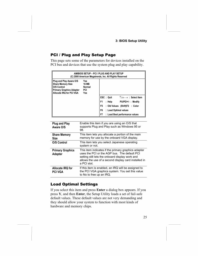
PCI / Plug and Play Setup PageThis page sets some of the parameters for devices installed on thePCI bus and devices that use the system plug and play capability.
AMIBIOS SETUP – PCI / PLUG AND PLAY SETUP(C) 2000 American Megatrends, Inc. All Rights Reserved
Plug and Play Aware O/S YesShare Memory Size 16 MBO/S Control NormalPrimary Graphics Adapter PCIAllocate IRQ for PCI VGA Yes
ESC : Quit ↑↓←→ : Select ItemF1 : Help PU/PD/+/- : ModifyF5 : Old Values (Shift)F2 : ColorF6 : Load Optimal valuesF7 : Load Best performance values
Plug and PlayAware O/S
Enable this item if you are using an O/S thatsupports Plug and Play such as Windows 95 or98.
Share MemorySize
This item lets you allocate a portion of the mainmemory for use by the onboard VGA display.
O/S Control This item lets you select Japanese operatingsystem or not.
Primary GraphicsAdapter
This item indicates if the primary graphics adapteruses the PCI or the AGP bus. The default PCIsetting still lets the onboard display work andallows the use of a second display card installed ina PCI slot.
Allocate IRQ forPCI VGA
If this item is enabled, an IRQ will be assigned tothe PCI VGA graphics system. You set this valueto No to free up an IRQ.
Load Optimal SettingsIf you select this item and press Enter a dialog box appears. If youpress Y, and then Enter, the Setup Utility loads a set of fail-safedefault values. These default values are not very demanding andthey should allow your system to function with most kinds ofhardware and memory chips.

Mainboard User’s Manual
26
Load Best Performance SettingsIf you select this item and press Enter a dialog box appears. If youpress Y, and then Enter, the Setup Utility loads a set of fail-safedefault values. These default values are not very demanding andthey should allow your system to function with most kinds ofhardware and memory chips.Note: It is highly recommended that users enter this option toload optimal values for accessing the best performance.
Features Setup PageThis page sets some of the parameters for peripheral devicesconnected to the system.
AMIBIOS SETUP – PERIPHERAL SETUP(C) 2000 American Megatrends, Inc. All Rights Reserved
OnBoard FDC EnabledOnBoard Serial Port 3F8h/COM1OnBoard IR Port DisabledOnBoard Parallel Port 378h Parallel Port Mode SPP Parallel Port IRQ 7 Parallel Port DMA N/AOnBoard Game Port 201hOnBoard MIDI Port 300h MIDI Port IRQ 10OnBoard PCI IDE BothOnBoard AC’97 Sound EnabledOnBoard AC’97 Modem AutoOnboard LAN EnabledUSB Function Support EnabledUSB Function for DOS Disabled
ESC : Quit ↑↓←→ : Select ItemF1 : Help PU/PD/+/- : ModifyF5 : Old Values (Shift)F2 : ColorF6 : Load Optimal valuesF7 : Load Best performance values
OnBoard FDC Use this item to enable or disable the onboardfloppy disk drive interface.
OnBoard SerialPort
Use this item to enable or disable the onboardCOM1 serial port, and to assign a port address.
OnBoard Ir Port Use this item to define the protocol for an infraredport if you have installed an optional IR port. Thechoices are IrDA and ASKIR.
Onboard ParallelPort
Use this item to enable or disable the onboardLPT1 parallel port, and to assign a port address.The Auto setting will detect and available address.

3: BIOS Setup Utility
27
Parallel Port Mode Use this item to set the parallel port mode. Youcan select SPP (Standard Parallel Port), ECP(Extended Capabilities Port), EPP (EnhancedParallel Port), or ECP + EPP.
Parallel Port IRQ Use this item to assign either IRQ 5 or 7 to theparallel port.
Parallel Port DMA Use this item to assign a DMA channel to theparallel port. The options are 0, 1 and 3.
OnBoard GamePort
Use this item to enable or disable the onboardgame port, and to assign a port address.
OnBoard MIDI Port Use this item to enable or disable the onboardMIDI port, and to assign a port address.
MIDI Port IRQ Use this item to assign an IRQ to the MIDI port.Onboard PCI IDE Use this item to enable or disable either or both of
the onboard Primary and Secondary IDEchannels.
AC’97 Sound This item enables or disables the onboard AC’97audio chip.
AC’97 Modem This item enables or disables the onboard AC’97modem chip.
Onboard LAN This item enables or disables the onboard LANchip.
USB FunctionSupport
Enable this item if you plan to use the USB portson this mainboard.
USB Function forDOS
Enable this item if you plan to use the USB portson this mainboard in a DOS environment.

Mainboard User’s Manual
28
CPU PnP Setup PageThis page lets you manually configure the mainboard for the CPU.The system will automatically detect the kind of CPU that youhave installed and make the appropriate adjustments to the itemson this page.
AMIBIOS SETUP – CPU PnP SETUP©2000 American Megatrends, Inc. All Rights Reserved
CPU BRAND AMD K7CPU Type DuronCPU Core Voltage 1.700 V
ESC : Quit ↑↓←→ : Select Item F1 : Help PU/PD/+/- : Modify F5 : Old Values (Shift)F2 : Color F6 : Load Optimal values F7 : Load Best performance values
CPU BRAND/Type/Core Voltage
These items show the brand, type and corevoltage of CPU that has installed in your system.
Note: If you manually set the wrong speed and the system won’trun properly, press the Page Up key while the system is bootingand a default setting will replace the incorrect CPU setting.

3: BIOS Setup Utility
29
Hardware Monitor PageThis page sets some of the parameters for the hardware monitoringfunction of this mainboard.
AMIBIOS SETUP – HARDWARE MONITOR(C) 2000 American Megatrends, Inc. All Rights Reserved
--- Hardware Monitor ---CPU Temperature 38°C/100°FSystem Temperature 30°C/86°FCPU Fan Speed 4500 RPMSystem Fan Speed 0 RPMVcore 1.616 VVcc25v 2.464 VVcc3 3.343 VVcc5.0 4.945 V+12V 12.000 V–12V -12.000 VSB3V 3.300 VSB5V 5.000 VVoltage Battery 3.360 V
ESC : Quit ↑↓←→ : Select ItemF1 : Help PU/PD/+/- : ModifyF5 : Old Values (Shift)F2 : ColorF6 : Load Optimal valuesF7 : Load Best performance values
CPU / SystemTemperature
These items display CPU and system temperaturemeasurement.
FANs & VoltageMeasurements
These items indicate cooling fan speeds in RPMand the various system voltage measurements.
Change PasswordIf you highlight this item and press Enter, a dialog box appearswhich lets you enter a Supervisor password. You can enter no morethan six letters or numbers. Press Enter after you have typed in thepassword. A second dialog box asks you to retype the password forconfirmation. Press Enter after you have retyped it correctly. Thepassword is then required to access the Setup Utility or for that andat start-up, depending on the setting of the Password Check itemin Advanced Setup.
Change or Remove the PasswordHighlight this item, press Enter and type in the current password.At the next dialog box, type in the new password, or just pressEnter to disable password protection.

Mainboard User’s Manual
30
ExitHighlight this item and press Enter to save the changes that youhave made in the Setup Utility configuration and exit the program.When the Save and Exit dialog box appears, press Y to save andexit, or press N to exit without saving.

4: Software & Applications
31
Chapter 4Software & Applications
IntroductionThis chapter describes the contents of the support CD-ROM thatcomes with the mainboard package.
The support CD-ROM contains all useful software, necessarydrivers and utility programs to properly run our products. Moreprogram information is available in a README file, located in thesame directory as the software.
To run the support CD, simply insert the CD into your CD-ROMdrive. An Auto Setup screen automatically pops out, and then youcan go on the auto-installing or manual installation depending onyour operating system.
If your operating system is Windows 98/ME/2000/XP, it willautomatically install all the drivers and utilities for yourmainboard; if Windows NT or manual installation, please followthe instructions described as the Installing under Windows NT orManual Installation section.

Mainboard User’s Manual
32
Installing Support Software1.Insert the support CD-ROM disc in the CD-ROM drive.2.When you insert the CD-ROM disc in the system CD-ROM drive, the CD automatically displays an Auto Setup screen.3.The screen displays three buttons of Setup, Browse CD and Exit on the right side, and three others Setup, Application and ReadMe at the bottom. Please see the following illustration.
The Setup button runs the software auto-installing program asexplained in next section.The Browse CD button is a standard Windows command that youcan check the contents of the disc with the Windows 98 filebrowsing interface.The Exit button closes the Auto Setup window. To run theprogram again, reinsert the CD-ROM disc in the drive; or click theCD-ROM driver from the Windows Explorer, and click the Setupicon.The Application button brings up a software menu. It shows thebundled software that this mainboard supports.The ReadMe brings you to the Install Path where you can find outpath names of software driver.

4: Software & Applications
33
Auto-Installing under Windows 98/ME/2000/XPIf you are under Windows 98/ME/2000/XP, please click the Setupbutton to run the software auto-installing program while the AutoSetup screen pops out after inserting the support CD-ROM:
1. The installation program loads and displays the following screen. Click the Next button.
2. Select the items that you want to setup by clicking on it (thedefault options are recommended). Click the Next button toproceed.
3. The support software will automatically install.
Once any of the installation procedures start, software isautomatically installed in sequence. You need to follow theonscreen instructions, confirm commands and allow the computerto restart as few times as needed to complete installing whateversoftware you selected. When the process is finished, all the supportsoftware will be installed and start working.

Mainboard User’s Manual
34
Installing under Windows NT or Manual InstallationIf you are under Windows NT, the auto-installing program doesn’twork out; or you have to do the manual installation, please followthis procedure while the Auto Setup screen pops out after insertingthe support CD-ROM:
1. Click the ReadMe to bring up a screen, and then click the Install Path at the bottom of the screen.2. Find out your mainboard model name and click on it to obtain its correct driver directory.3. Install each software in accordance with the corresponding driver path.
Bundled Software InstallationAll bundled software available on the CD-ROM is for users’convenience. You can install bundled software as follows:1. Click the Application button while the Auto Setup screen pops out after inserting the support CD-ROM.2. A software menu appears. Click the software you want to install.3. Follow onscreen instructions to install the software program step by step until finished.