traffic controller design manual - ministry of transportation
TRANSCRIPT

Electrical Engineering Centre INTRODUCTION JANUARY 8 2004 Traffic Controller Design Manual
TRAFFIC CONTROLLER DESIGN MANUAL
Electrical Engineering Centre
Version 2.0 January 2004

Electrical Engineering Centre INTRODUCTION JANUARY 8 2004 Traffic Controller Design Manual
TRAFFIC CONTROLLER DESIGN MANUAL Table of Contents
100 Policies and Procedures
200 Signal Installation Process
300 Traffic Controller Design
400 Traffic Controller Cabinet Assembly
500 Signal Commissioning Guidelines
600 Traffic Operations Guidelines

Section 100 POLICIES AND PROCEDURES
Electrical Engineering Centre
Version 3.0 January 2004

TABLE OF CONTENTS
Electrical Engineering Centre 100 POLICIES AND PROCEDURES January, 04
Traffic Controller Design Manual Pageiii
101 TRAFFIC CONTROLLER DESIGN POLICY................................................. 1 101.1 Introduction..................................................................................................... 1 101.2 Definitions ...................................................................................................... 1 101.3 Policy .............................................................................................................. 1 101.4 Permitted Exceptions to Policy....................................................................... 2 101.5 Costs................................................................................................................ 2 101.6 Failure to Comply ........................................................................................... 2
102 MANAGING A TRAFFIC CONTROLLER PROJECT.................................. 3 102.1 Introduction..................................................................................................... 3 102.2 Procedures....................................................................................................... 3
103 TRAFFIC CONTROLLER ASSEMBLY AUDITS .......................................... 6 103.1 Introduction..................................................................................................... 6 103.2 Procedures....................................................................................................... 6

Electrical Engineering Centre 100 POLICIES AND PROCEDURES January, 04
Traffic Controller Design Manual Page 1
101 TRAFFIC CONTROLLER DESIGN POLICY
101.1 INTRODUCTION
.1 This document has been prepared to clearly outline the policies related to roles and responsibilities of the various departments responsible for supplying, designing, and commissioning Ministry-owned traffic controller equipment.
.2 Traffic controller equipment must be designed as per the appropriate standards.
101.2 DEFINITIONS
.1 For the purposes of this document, the following definitions are used:
.2 Traffic signal – consists of all of the equipment required to operate a traffic-controlled intersection as per the required standards (i.e. traffic controller assembly, signal head, poles, cabling, etc.)
.3 Traffic Controller Assembly (TCA) - consists of the traffic controller cabinet c/w all internal components.
.4 Traffic Controller design – consists of the design of the traffic controller assembly to allow it to perform as per the traffic engineering operational requirements.
101.3 POLICY
.1 All designs for new traffic controller equipment and designs for modifications to existing traffic controller equipment shall be managedby the Traffic Controller Group (TCG) at the Electrical EngineeringCentre (EEC). See Section 102 for this management process.
.2 Traffic controller designs shall be assigned to an approved Traffic Controller Designer (TCD).
.3 This policy applies to installation of new traffic signals, changing phasing at an existing signal, adding pre-emption to an existing signal, and all other situations not specifically excluded later in this document.
101.4 PERMITTED EXCEPTIONS TO POLICY
.1 There is only one situation where the Electrical Maintenance Contractor(EMC) is not required to have the EEC TCG manage a traffic controller modification: MVA Temporary Traffic Signals.

POLICY
Electrical Engineering Centre 100 POLICIES AND PROCEDURES January, 04
Traffic Controller Design Manual Page 2
.1 It is recognized that when a traffic controller assembly in the field is damaged due to an MVA, the EMC may install a temporary traffic controller assembly at the intersection. This TCA is only temporary in nature and a new TCA shall be ordered through the Manager Electrical Services (MES) via the regular process as per Section 102.
.2 If the MES wishes to keep the temporary traffic controller assembly in the field on a permanent basis OR wishes to install another traffic controller from their inventory at the site, the MES shall follow the regular process for a new traffic controller assembly as per Section 102.
.2 For all other controller modifications, EMC must comply with the procedures outlined in Section 102
101.5 COSTS
.1 The TCG has standardized costs for the design and supply of new and modifications to existing traffic controller assemblies. All prices should be negotiated via CFS.
101.6 AUDITING
.1 The EEC shall audit for compliance to these policies.
POLICY
Electrical Engineering Centre 100 POLICIES AND PROCEDURES January, 04
Traffic Controller Design Manual Page 3
102 MANAGING A TRAFFIC CONTROLLER PROJECT
102.1 INTRODUCTION
.1 This section outlines the procedures that shall be followed to ensure a successful implementation of a Traffic Controller project. These procedures consist of the Preliminary Project Information stage, Design stage, Construction/Assembly & Testing stage and Project Completion (project installed in the field) stage.
.2 For new traffic controller designs, the TCD is responsible for design, assembly and testing. For modification to an existing traffic controller, the TCD is responsible for design and the EMC is responsible for assembly, testing and implementation.
102.2 PROCEDURES
.1 The Traffic Controller Coordinator (TCC) at the EEC shall gather any information received about a project and record the receipt of the information in the Preliminary Project Information sheet of the PRIORITY.xls worksheet.
.2 The TCC shall only move a project record from the Preliminary Project Information sheet to the Projects sheet (under New Projects) once the EEC has received a financial commitment for the project via a signed CFS agreement.
.3 A project shall not proceed any further until all documentation needed to complete the project has been provided to the TCC. The list of required documents is as follows:
Signed Contract for Services (CFS) Signed Traffic Engineering Check Sheet. (TEC) Signed and sealed Signal Timing Sheet. (STS). Signed and sealed Intersection Electrical Drawings. (INTER-DWGS).
.4 Once the TCC has received all the documentation (CFS, TEC, STS & INTER-DWGS), the project record shall be moved from the NewProjects section to Projects Ready For Design section and shall be assigned to an approved Traffic Control Designer. The ConstructionDocument (CST) shall be used by all Traffic Control Designers to record all modifications needed to the internal wiring of a Traffic Controller

POLICY
Electrical Engineering Centre 100 POLICIES AND PROCEDURES January, 04
Traffic Controller Design Manual Page 4
Assembly (TCA) as well as any explanation of operational features that are required and all non standard programming requirements.
.5 The TCD shall notify the TCC of the start date of a project design. Upon receipt of this date the TCC shall move the project record from the Projects Ready For Design section to the Projects Under Design & Construction section.
.6 The TCD shall notify the TCC when the design is complete as well as when construction/assembly work has started. The TCC shall record these dates. If the project is a modification to an existing traffic controller that is to be constructed/assembled by the EMC, all documentation and equipment needed for the project shall be shipped to the EMC by the EEC. The TCC shall move the project record from Projects Under Design & Construction to the Project Shipped sheet.
.7 All construction/assembly shall be in full accordance with the design documentation issued by the TCD. The design documentation package consists of the following:
Construction Document (CST)
Loop Assignment Sheet (LAS)
Signal Timing Sheet (STS)
Set of TCA Schematics (DWG)
.8 The constructed/assembled project shall be fully tested as if the project is operating in the field. This is to ensure that the TCA will operate as per the Traffic Engineering Check Sheet (TEC) requirements. If at this point any changes and/or modifications are needed then the assigned Traffic Control Designer shall be notified of the changes.
.9 The Traffic Control Designer shall update the design documentation to reflect the new requirements and then shall issue a new set of design documentation. Once the changes have been made a second full test shall be conducted to ensure that the traffic controller operates as per the Traffic Engineering Check Sheet (TEC) requirements.
.10 The EMC shall notify the TCC once the project has moved from the pre-field install test to the ready to install in the field stage. EMC shall notify the TCC via e-mail.
.11 The EMC shall now commission the traffic controller
POLICY
Electrical Engineering Centre 100 POLICIES AND PROCEDURES January, 04
Traffic Controller Design Manual Page 5
.12 The EMC shall notify the TCC when a project has been completed and is fully operational in the field via a fax or email using the Traffic Signal Record form. The TCC shall move the project record from the PROJECT SHIPPED to the PROJECT COMPLETED sheet. The EMC shall be responsible for ensuring that the correct documentation is located in the operational TCA.
Note: The design documentation that the EEC has on file shall be used when the EEC TCC conducts a regional TCA audit as per Section 103. It is important that documentation at all sites (EMC, TCA and EEC) be identical.

Electrical Engineering Centre 100 POLICIES AND PROCEDURES January, 04
Traffic Controller Design Manual Page 6
103 TRAFFIC CONTROLLER ASSEMBLY AUDITS
103.1 INTRODUCTION
.1 It is the responsibility of the Electrical Engineering Centre (EEC) to conduct periodic field audits of Traffic Controller Assemblies (TCA) that are installed and operating throughout the Province. An audit shall involve the original design documents held at the EEC, the intersection record documents held at the EMC and record documents that reside in the TCA at the intersection.
103.2 PROCEDURES
.1 The EEC representative shall be assigned to conduct an audit in a particular region.
.2 The EEC shall notify the MES that an audit is to be conducted in their region and arrange for an acceptable on site date.
.3 The EEC Rep shall assemble a list of signalized intersections that have been selected for the audit.
.4 A copy of all the design documentation held by the EEC shall be made for each of the selected signalized intersections.
.5 The EEC Rep shall meet with the MES or designate to obtain the intersection record files of the intersections that will be audited.
.6 The EEC Rep shall compare the regional intersection record documentation with the set from the EEC. Any disparity between the documentation shall be recorded and will be used in the final audit report.

Electrical Engineering Centre 100 POLICIES AND PROCEDURES January, 04
Traffic Controller Design Manual Page 7
.7 The EEC Rep shall proceed to the selected intersection where a visual record of the intersection shall be made and a comparison made between the intersection TCA documentation, the EMC documentation, the EEC documentation and what is actually installed in the intersection. Any disparity between the documentation shall be recorded and shall be used in the final audit report.
.8 The EEC Rep shall compile a Non Compliance Report (NCR), listing clearly any deficiencies that should be corrected with any of the documentation.
.9 The EEC Rep shall follow up to confirm all corrections have been made on the NCR.
Section 200 SIGNAL INSTALLATION PROCESS
See the following URL for information: http://www.th.gov.bc.ca/publications/eng_publications/TE_Bulletins/TE_bulletins.htm
Electrical Engineering Centre
Version 2.0 January 2004

Section 300 TRAFFIC CONTROLLER DESIGN
Electrical Engineering Centre
Version 2.0 January 2004

TABLE OF CONTENTS
Electrical Engineering Centre 300 CONTROLLER DESIGN January, 04
Traffic Controller Design Manual Page iii
300 TRAFFIC CONTROLLER DESIGN
301 INTRODUCTION................................................................................................... 1
301.1 SECTION SUMMARY..........................................................................................1
302 WORKING FILE.................................................................................................... 2
302.1 INTRODUCTION .................................................................................................2
302.2 POLICY................................................................................................................2
302.3 PROCEDURES....................................................................................................3 302.3.1 Creating a Working File .....................................................................3 302.3.2 Contents of a Working File ................................................................3
303 TRAFFIC CONTROLLER PRIORITY LIST .......................................................... 5
303.1 INTRODUCTION .................................................................................................5
303.2 SCOPE AND REQUIREMENTS..........................................................................5
303.3 TRAFFIC CONTROLLER PRIORITY LIST ROLES AND RESPONSIBILTY .....6
303.4 TRAFFIC CONTROLLER PRIORITY LIST POLICY AND PROCEDURE ..........6 303.4.1 Archiving ............................................................................................6 303.4.2 Access ...............................................................................................7 303.4.3 Changes or Additions to the Traffic Controller Priority List ..............7
303.5 WORKBOOK DESCRIPTION..............................................................................8
303.6 WORKSHEET INFORMATION ...........................................................................9
304 STANDARD TRAFFIC CONTROLLER DRAWINGS ......................................... 12
304.1 INTRODUCTION ...............................................................................................12
304.2 POLICY..............................................................................................................12
304.3 TYPES OF TRAFFIC CONTROLLER CABINET ASSEMBLES .......................12 304.3.1 Four phase.......................................................................................12 304.3.2 Eight phase......................................................................................12
304.4 NAMING CONVENTIONS AND DESCRIPTIONS ............................................13 304.4.1 Factory Original Drawing .................................................................13 304.4.2 Template Drawings..........................................................................13 304.4.3 Directory Structure for Template Drawings .....................................14 304.4.4 Naming conventions for four phase cabinet template drawings .....15 304.4.5 Naming conventions for eight phase cabinet template drawings....17

TABLE OF CONTENTS
Electrical Engineering Centre 300 CONTROLLER DESIGN January, 04
Traffic Controller Design Manual Page iv
304.5 DRAFTING STANDARDS .................................................................................17304.5.1 Policy ...............................................................................................17 304.5.2 Drawing Sizes, Text, Layers, and Colours ......................................17
305 DESIGN PROCESS ............................................................................................ 18
305.1 INTRODUCTION ...............................................................................................18
305.2 ROLES AND RESPONSIBILITIES ....................................................................19
305.3 TRAFFIC CONTROLLER CONSTRUCTION DOCUMENT..............................20 305.3.1 Naming convention of Traffic Controller Construction Document. .20 305.3.2 Traffic Controller Construction Document Sections ........................20
305.4 CORRESPONDENCE FILE ..............................................................................22 305.4.2 Naming convention of correspondence file. ....................................22
305.5 LOOP ASSIGNMENT PROCESS .....................................................................22 305.5.2 Naming Conventions .......................................................................22 305.5.3 General Information.........................................................................23
305.6 LOOP ASSIGNMENT SHEET ...........................................................................23 305.6.2 Loop Number ...................................................................................24 305.6.3 Loop Assignment Example..............................................................24 305.6.4 Detector Unit....................................................................................28 305.6.5 CU Input (Controller Unit Input) .......................................................28 305.6.6 Movement ........................................................................................28 305.6.7 Phase...............................................................................................28 305.6.8 Measure of Efficiency (MOE)...........................................................28 305.6.9 Count ...............................................................................................29 305.6.10 Mode................................................................................................29 305.6.11 Delay................................................................................................29 305.6.12 Stretch .............................................................................................29
305.7 DRAWING SELECTION ....................................................................................30 305.7.1 Selecting a Template Drawing.........................................................30 305.7.2 Naming Conventions .......................................................................30
305.8 DRAWING MODIFICATION ..............................................................................31 305.8.1 Title Block ........................................................................................31
305.9 EIGHT PHASE DRAWING SHEETS.................................................................32 305.9.1 Front Drawing ..................................................................................32 305.9.2 Rear Drawing...................................................................................39 305.9.3 Harness Drawing .............................................................................46
305.10 FOUR PHASE DRAWING SHEETS..................................................................48
TABLE OF CONTENTS
Electrical Engineering Centre 300 CONTROLLER DESIGN January, 04
Traffic Controller Design Manual Page v
305.10.1 Front Drawing ..................................................................................48 305.10.2 Harness Drawing .............................................................................50
305.11 EEC QUALITY CONTROL CHECK...................................................................50
305.12 TRAFFIC CONTROLLER EQUIPMENT ...........................................................51 305.12.1 Ordering Components .....................................................................51
305.13 TRAFFIC CONTROLLER CONSTRUCTION PACKAGE .................................51
Electrical Engineering Centre 300 CONTROLLER DESIGN January, 04
Traffic Controller Design Manual Page 1
301 INTRODUCTION
301.1 SECTION SUMMARY
.1 This section describes what methods and information the Electrical Engineering Centre (EEC) uses to design a Traffic Controller, for a standard traffic signal intersection.

Electrical Engineering Centre 300 CONTROLLER DESIGN January, 04
Traffic Controller Design Manual Page 2
302 WORKING FILE
302.1 INTRODUCTION
.1 This chapter describes the policies and procedures that the Traffic Controller Designer must follow in creating and implementing a working file. A separate working file is created for each new project (intersection). This file consists of one file folder containing all drawings, Traffic Controller Construction Document and correspondence relating to the design and construction of the traffic controller. The Traffic Controller Designer is responsible for the working files and shall make it accessible to others until the project is complete. Once the project is complete the working file is added to the permanent intersection file.
302.2 POLICY
.1 The Traffic Controller Designer shall use standard configuration and set-up procedures that are approved by the EEC. Any changes to these procedures shall be in writing.
.2 The Traffic Controller Designer is responsible for creating and maintaining all working files and ensuring that permanent intersection files located at the EEC are updated with new traffic controller information when designs are complete and implemented.
.3 A permanent active intersection file shall be kept for the life of the controlled intersection plus 7 years. All inactive information (dead information file) shall be stored for 7 years (i.e. nothing is discarded until that time).
.4 Working files shall be available for audit by the Manager, EEC, or his designate.
.5 All permanent intersection files shall conform to the Operation Records Classification System (ORCS).

PROCEDURES
Electrical Engineering Centre 300 CONTROLLER DESIGN January, 04
Traffic Controller Design Manual Page 3
302.3 PROCEDURES
302.3.1 Creating a Working File
.1 A working file shall be created by the EEC Traffic Controller Group, when the first correspondence has been received from a Region or District, requesting a traffic controller improvement to a intersection.
.2 The EEC Traffic Controller Group will assign a project working file to a Traffic Controller Designer when all the pre-requisites have been met. As listed in 303.2.2
.3 The Traffic Controller Designer shall assemble in one working file all required documents and drawings for this project. As listed in 302.3.2
.4 When the project is completed and implemented all appropriate electronic and paper documentation must returned to the EEC this file will be added to the permanent intersection file.
302.3.2 Contents of a Working File
.1 All correspondence relating to the project. Paper and electronic correspondence files.
.2 Traffic Engineering Checklist is a Pre-requisite to project construction. (Refer to Traffic Signal Program Development and Implementation Guidelines).
.3 Financial approval is a Pre-requisite to project construction. This is in the form of a CFS authorising charges to a Regional account.
.4 Signal Timing Sheet is a Pre-requisite to project construction (signed or signed and sealed by an Engineer).
.5 Electrical Intersection Drawings (signed and sealed by an Engineer) is a Pre-requisite to project construction.. Note: Only Electrical Intersection Drawings containing information relevant to the traffic signal are kept in the working file. (i.e. 1:250 Site Plan, Loop Table, Signal Display, Pole Elevations, etc.)
.6 Loop Assignment Sheet
.7 Traffic Controller Drawings
.8 Traffic Controller Construction Document

PROCEDURES
Electrical Engineering Centre 300 CONTROLLER DESIGN January, 04
Traffic Controller Design Manual Page 4
.9 Controller Unit Programming Data Capture (Data Dump)
Electrical Engineering Centre 300 CONTROLLER DESIGN January, 04
Traffic Controller Design Manual Page 5
303 TRAFFIC CONTROLLER PRIORITY LIST
303.1 INTRODUCTION
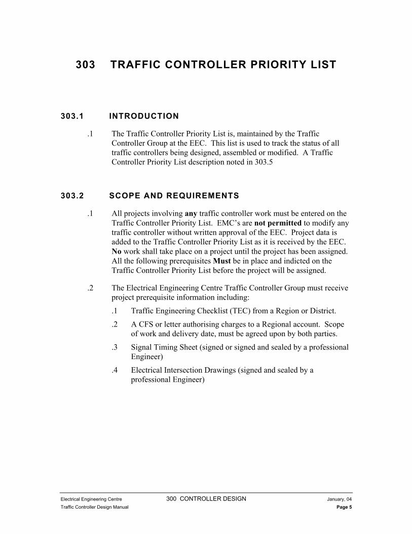
.1 The Traffic Controller Priority List is, maintained by the Traffic Controller Group at the EEC. This list is used to track the status of all traffic controllers being designed, assembled or modified. A Traffic Controller Priority List description noted in 303.5
303.2 SCOPE AND REQUIREMENTS
.1 All projects involving any traffic controller work must be entered on the Traffic Controller Priority List. EMC’s are not permitted to modify any traffic controller without written approval of the EEC. Project data is added to the Traffic Controller Priority List as it is received by the EEC.No work shall take place on a project until the project has been assigned.All the following prerequisites Must be in place and indicted on the Traffic Controller Priority List before the project will be assigned.
.2 The Electrical Engineering Centre Traffic Controller Group must receive project prerequisite information including:
.1 Traffic Engineering Checklist (TEC) from a Region or District.
.2 A CFS or letter authorising charges to a Regional account. Scope of work and delivery date, must be agreed upon by both parties.
.3 Signal Timing Sheet (signed or signed and sealed by a professional Engineer)
.4 Electrical Intersection Drawings (signed and sealed by a professional Engineer)

TRAFFIC CONTROLLER PRIORITY LIST ROLES AND RESPONSIBILTY
Electrical Engineering Centre 300 CONTROLLER DESIGN January, 04
Traffic Controller Design Manual Page 6
303.3 TRAFFIC CONTROLLER PRIORITY LIST ROLES AND RESPONSIBILTY
.1 The Traffic Controller Priority List is, maintained by the EEC. Traffic Controller Group.
.2 It is the responsibility of the project manager to inform the EEC. Traffic Controller Group, in writing, of any changes in the status of their projects. The project manager in this case is anyone who is assigned to deliver the signal installation or modification. See Section 303.4.3
.3 It is the responsibility of the EEC. Traffic Controller Group to provide the project manager with weekly status reports for projects in the form of an updated Traffic Controller Priority List. The updated Traffic Controller Priority List shall be sent via email. See section 303.4.3
.4 Placement on the email list is the responsibility of the project manager or interested party. Contact the EEC Traffic Controller Group for listing.
303.4 TRAFFIC CONTROLLER PRIORITY LIST POLICY AND PROCEDURE
303.4.1 Archiving
.1 A “snapshot” of the Traffic Controller Priority List shall be made each week by EEC Traffic Controller Group by the renaming and saving the updated version as follows:
Figure 1. Traffic Controller Priority List Snapshot Naming Convention
TRAFFIC CONTROLLER PRIORITY LIST POLICY AND PROCEDURE
Electrical Engineering Centre 300 CONTROLLER DESIGN January, 04
Traffic Controller Design Manual Page 7
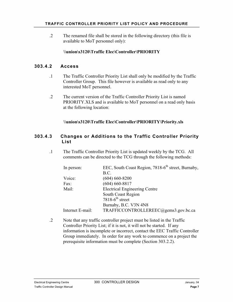
.2 The renamed file shall be stored in the following directory (this file is available to MoT personnel only):
\\union\s3120\Traffic Elec\Controller\PRIORITY
303.4.2 Access
.1 The Traffic Controller Priority List shall only be modified by the Traffic Controller Group. This file however is available as read only to any interested MoT personnel.
.2 The current version of the Traffic Controller Priority List is named PRIORITY.XLS and is available to MoT personnel on a read only basis at the following location:
\\union\s3120\Traffic Elec\Controller\PRIORITY\Priority.xls
303.4.3 Changes or Additions to the Traffic Controller Priority List
.1 The Traffic Controller Priority List is updated weekly by the TCG. All comments can be directed to the TCG through the following methods:
In person: EEC, South Coast Region, 7818-6th street, Burnaby, B.C.
Voice: (604) 660-8200 Fax: (604) 660-8817 Mail: Electrical Engineering Centre South Coast Region 7818-6th street Burnaby, B.C. V3N 4N8 Internet E-mail: [email protected]
.2 Note that any traffic controller project must be listed in the Traffic Controller Priority List; if it is not, it will not be started. If any information is incomplete or incorrect, contact the EEC Traffic Controller Group immediately. In order for any work to commence on a project the prerequisite information must be complete (Section 303.2.2).

WORKBOOK DESCRIPTION
Electrical Engineering Centre 300 CONTROLLER DESIGN January, 04
Traffic Controller Design Manual Page 8
303.5 WORKBOOK DESCRIPTION The EXCEL file PRIORITY.XLS is comprised of five tab folders, which denotes the progress of each project.
1. LINKSThis folder tab is used by EEC to create a project data file for design and construction.
2. PROJECTSThis folder tab lists all projects that are Under Design and Construction, Ready For Design, New Projects Pending Review, Projects on Hold. The sheet is arranged in Regions and the tab header indicates fiscal year.
3. SHIPPEDThis folder tab lists all projects that have been shipped to the Regional Electrical Crews for installation and or cabinet construction and completion. The sheet is arranged in Regions and the tab header indicates fiscal year.
4. COMPLETEDThis folder tab lists all projects that have been completed and are fully operational in the current fiscal year. The sheet is arranged in Regions and the tab header indicates fiscal year.
5. LAST YEAR PROJECTSThis folder tab lists all last fiscal year projects that have been sent but not field implemented. The sheet is arranged in Regions.

WORKSHEET INFORMATION
Electrical Engineering Centre 300 CONTROLLER DESIGN January, 04
Traffic Controller Design Manual Page 9
303.6 WORKSHEET INFORMATION Each of the above worksheets is comprised of 25 columns. The CFS Number, Timing Sheet and Intersection plans columns must be completed as a prerequisite to project construction. Columns will contain data as it is received. Data entries listed as follows:
1. COLUMN A - CFS NUMBERThis normally contains the CFS “number”, which accounts for materials and labour to deliver the traffic controller project in a single fiscal year. Where projects cross a fiscal boundary, this can be divided into separate CFS to cover equipment (M) and labour (LAB). Motor Vehicle Accidents would be funded by a damage to government property number example. “CMC-?????”.
2. COLUMN B - TIMING SHEETThis indicates Signal Timing Sheet for this project. Most projects require a new Signal Timing Sheet. When the Signal Timing Sheet is received by the EEC the Signal Timing Sheet “Date” will be indicated. For projects that can use an existing Signal Timing Sheet an “EX” will be indicated.
3. COLUMN C – TRAF ENG CHK SHEETThis indicates if a Traffic Engineering Checking Sheet has been received for this project. Most projects require an Traffic Engineering check sheet for the construction or modification on a traffic controller cabinet. When a Traffic Engineering check sheet has been received for a project it will be indicated by the “Date” the Traffic Engineer signed the check list.
4. COLUMN D - INTER PLANS (Intersection Drawings)This indicates if Intersection Drawings have been received for this project. Most projects require new Intersection Drawings. For projects that require new Intersection Drawings. When the drawings are received by EEC an “X” will be indicated. For projects that can use existing Intersection drawings an “EX” will be indicated.
5. COLUMN E - DRAWING NUMBERThis indicates the drawing TE number and Rev level of the project. The EEC utilises this as a unique identifier.

WORKSHEET INFORMATION
Electrical Engineering Centre 300 CONTROLLER DESIGN January, 04
Traffic Controller Design Manual Page 10
6. COLUMN F - LOCATIONThis describes the actual project intersection location.
7. COLUMN G - CITYThis denotes the city that the project resides in.
8. COLUMN H - REGIONThis denotes the Region that the project is being delivered to.
9. COLUMN I - EEC TO DELIVER BY This indicates the date that you wish to have the traffic controller to the Region. Provide the EEC with all prerequisite information two months prior to this date, the EEC will provide the traffic controller before this date.
10. COLUMN J - COMMENTSThis provides a brief description on the scope of the project.
11. COLUMN K - PROJECT SPONSORThis lists the person requesting the traffic controller project usually the project manager.
12. COLUMN L - CONTACT NUMBERThis indicates the project sponsors contact phone number.
13. COLUMN M - PRE-PAIDThis indicates if the equipment was funded in a previous fiscal year. Equipment indicated by an “M” and total costs pre-paid indicated by an “X”.
14. COLUMN N - OLD CFS NUMBER This indicates the CFS number from the previous fiscal year on this project.
15. COLUMN O - TIME SYS NUMBERThis indicates the project number (internal to EEC).
16. COLUMN P – CA (Controller Assembly)This indicates the traffic controller cabinet type required for the project. An “S” shall be indicated for an 8 phase cabinet and an “M”for and 4 phase cabinet.
17. COLUMN Q – CU (Traffic Controller Unit LMD Etc.)This indicates whether a new Traffic Controller Unit (mainframe) is to be included with this project.

WORKSHEET INFORMATION
Electrical Engineering Centre 300 CONTROLLER DESIGN January, 04
Traffic Controller Design Manual Page 11
18. COLUMN R – CMU (Conflict Monitor Unit)This indicates whether a new Conflict Monitor Unit is to be included with this project.
19. COLUMN S – MODEMThis indicates whether a modem is to be included in this project.
20. COLUMN T - WHO BUILDThis indicates who will actually perform the labour to complete this project.
21. COLUMN U - PROJECT DESIGNERThis indicates who Traffic Controller Designer is for this project.
22. COLUMN V – DESIGN START DATEThis indicates the date that this project was initiated.
23. COLUMN W - READY FOR CONSTRUCTThis indicates the date that this project was ready for design (i.e. CFS, Signal Timing Sheet and Electrical Intersection Drawings available). This date is used to provide the required two-month turnaround time.
24. COLUMN X - READY TO INSTALL This indicates the date that this project has been completed and is ready for field installation.
25. COLUMN Y - EQUIPMENT SHIPPED DATEThis indicates the date that this project was shipped from the EEC to the Regional Electrical Shop.
26. COLUMN Z - COMPLETION DATEThis indicates the date that the Region reported (by i.e. E-mail and or FAX) to the EEC that the project was installed and fully operational. Note the EEC must be notified any improvements to Traffic controller operation.

INTRODUCTION
Electrical Engineering Centre 300 CONTROLLER DESIGN January, 04
Traffic Controller Design Manual Page 12
304 STANDARD TRAFFIC CONTROLLER DRAWINGS
304.1 INTRODUCTION
.1 This section describes the types, naming conventions and descriptions of standard traffic controller drawings and drafting standards used for traffic controller design.
304.2 POLICY
.1 Drawings shall only be modified accordance to the procedures noted in this manual or as approved in writing by the Manager of EEC or designate.
304.3 TYPES OF TRAFFIC CONTROLLER CABINET ASSEMBLES
304.3.1 Four phase
.1 The four phase cabinet is the Ministry’s standard traffic controller cabinet for intersections with 4 phases or less. The cabinet has two associated drawing sheets as described in Section 304.4.4
304.3.2 Eight phase
.1 The eight phase is the Ministry’s standard traffic controller cabinet for intersections with more than 4 phases. The cabinet has 3 associated drawing sheets as described in Section.304.4.5

NAMING CONVENTIONS AND DESCRIPTIONS
Electrical Engineering Centre 300 CONTROLLER DESIGN January, 04
Traffic Controller Design Manual Page 13
304.4 NAMING CONVENTIONS AND DESCRIPTIONS
304.4.1 Factory Original Drawing
.1 Each production run of traffic controller cabinets (four or eight phase), has associated tendered drawings for the series of traffic controller cabinets as they are to be built by the cabinet manufacturer. The drawings are referred to as the “Factory Original” drawings and are used as a basis to create “Template Drawings” for the cabinet series. Traffic controller cabinets are purchased in bulk and each production run of traffic controller cabinets is given a series number. The series number can then be used to track any problems or changes that are particular to each production run of cabinets. Factory original drawing files are labelled as shown in Figure 2.
4FACTXXH
Figure 2 - Factory Original Filename Standard
.2 The factory original drawings are only used by the EEC to create template drawings. TCD’s will use template drawings, not factory original drawings.
304.4.2 Template Drawings
.1 “Template” drawings are factory original drawings that have modified to be used as templates in traffic controller design on standard intersections. Template drawings are created by the EEC for common intersections so that only minor modifications are required to complete traffic controller drawing sheets.
No. of Phases
Series #Factory Original Drawing
Drawing name Abbreviation (F for Front, H for Harness, R for Rear)

NAMING CONVENTIONS AND DESCRIPTIONS
Electrical Engineering Centre 300 CONTROLLER DESIGN January, 04
Traffic Controller Design Manual Page 14
.2 The creation of the template drawings is a dynamic process. As intersections with specific design requirements arise, new template drawings are created. Due to the nature of this process, intersections with special design requirements may not have template drawings.
304.4.3 Directory Structure for Template Drawings
.1 The template drawings for the common intersections are stored in directories. The following sections are guidelines to follow for naming directories. The general form of the directory name is shown in Figure 3.
Figure 3. Template Directory Naming Convention
.2 The first character of the template drawing directory name is the traffic controller cabinet type. (Either ‘4’ or ‘8’ phase)
.3 The eighth character of the template drawing directory name is the traffic controller cabinet series number.
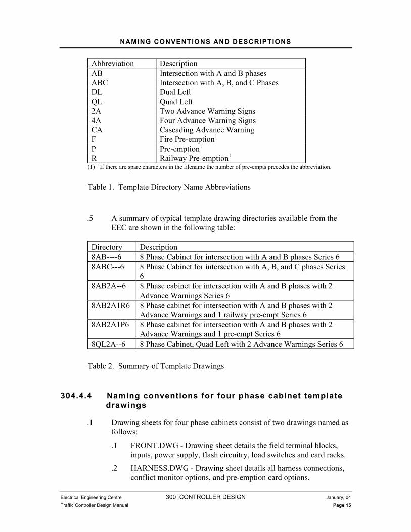
.4 The second to seventh characters are abbreviations that describe special features contained on the drawings such as phase descriptions, advance warning, and pre-empt. Table 1 shows the abbreviations to be used when naming template drawings. The order that the abbreviations are entered in the directory name is from top to bottom in the table. If all eight characters of the directory name are not required, empty spaces are filled with dashes.
NAMING CONVENTIONS AND DESCRIPTIONS
Electrical Engineering Centre 300 CONTROLLER DESIGN January, 04
Traffic Controller Design Manual Page 15
Abbreviation Description AB Intersection with A and B phases ABC Intersection with A, B, and C Phases DL Dual Left QL Quad Left 2A Two Advance Warning Signs 4A Four Advance Warning Signs CA Cascading Advance Warning F Fire Pre-emption1
P Pre-emption1
R Railway Pre-emption1
(1) If there are spare characters in the filename the number of pre-empts precedes the abbreviation.
Table 1. Template Directory Name Abbreviations
.5 A summary of typical template drawing directories available from the EEC are shown in the following table:
Directory Description 8AB----6 8 Phase Cabinet for intersection with A and B phases Series 6 8ABC---6 8 Phase Cabinet for intersection with A, B, and C phases Series
68AB2A--6 8 Phase cabinet for intersection with A and B phases with 2
Advance Warnings Series 6 8AB2A1R6 8 Phase cabinet for intersection with A and B phases with 2
Advance Warnings and 1 railway pre-empt Series 6 8AB2A1P6 8 Phase cabinet for intersection with A and B phases with 2
Advance Warnings and 1 pre-empt Series 6 8QL2A--6 8 Phase Cabinet, Quad Left with 2 Advance Warnings Series 6
Table 2. Summary of Template Drawings
304.4.4 Naming conventions for four phase cabinet template drawings
.1 Drawing sheets for four phase cabinets consist of two drawings named as follows:
.1 FRONT.DWG - Drawing sheet details the field terminal blocks, inputs, power supply, flash circuitry, load switches and card racks.
.2 HARNESS.DWG - Drawing sheet details all harness connections, conflict monitor options, and pre-emption card options.

NAMING CONVENTIONS AND DESCRIPTIONS
Electrical Engineering Centre 300 CONTROLLER DESIGN January, 04
Traffic Controller Design Manual Page 16
.3 Note that all four phase template drawings have common names (i.e. all are named FRONT.DWG and HARNESS.DWG); the only differentiating characteristics are the directory where they are stored and the title blocks of the actual drawings.
DRAFTING STANDARDS
Electrical Engineering Centre 300 CONTROLLER DESIGN January, 04
Traffic Controller Design Manual Page 17
304.4.5 Naming conventions for eight phase cabinet template drawings
.1 Drawing sheets for eight phase cabinets consist of three drawings named as follows:
.1 FRONT.DWG - Drawing sheet details the field terminal blocks, inputs, power supply, flash circuitry, load switches and card racks.
.2 HARNESS.DWG - Drawing sheet details all harness connection details, conflict monitor options, and pre-emption card options.
.3 REAR.DWG - Drawing sheet details the field loop connections, power supply assembly and back panel terminal wiring.
.4 Note that all eight phase template drawings have common names (i.e. all are named FRONT.DWG, HARNESS.DWG and REAR.DWG); the only differentiating characteristics are the directory where they are stored and the title blocks of the actual drawings.
304.5 DRAFTING STANDARDS
304.5.1 Policy
.1 Traffic Controller Drawings are to be saved in the version of AutoCAD currently in use by the Ministry. Contact the EEC for information on the current release in use.
.2 All drawing filenames are a maximum of 8 characters long. Naming conventions are described in Section 304.4.
.3 A complete set of drafting standards will be developed by the EEC. Until the standards are complete contact the EEC with any questions.
304.5.2 Drawing Sizes, Text, Layers, and Colours
.1 Normally, only modification of existing drawing components is required. If entities need to be created, copy existing entities to create new ones.

Electrical Engineering Centre 300 CONTROLLER DESIGN January, 04
Traffic Controller Design Manual Page 18
305 DESIGN PROCESS
305.1 INTRODUCTION
.1 This chapter describes the procedures involved in the traffic controller design process. The steps involved in the design process are Traffic Controller Construction Document, Loop Assignment Sheet and Traffic Controller Drawings.
.2 The first section of the Controller Construction Document contains the Traffic Controller Construction Order including General scope, Project Documents Notes and Project Profile. A copy of this is taped to the cabinet designated for the project. Other sections of the document include:
.1 Wiring Modifications
.2 Installed Equipment
.3 Drawing Modifications
.4 Special Feature Programming
.5 Finishing Procedures
.6 EEC Final Test-N-Checkout form
.7 EEC Quality Control Check List
.8 Withdrawal Form
.3 Project Correspondence file.
.1 All information via e-mail or noted from persons involved in project shall be contained in this file.
.4 The Loop Assignment Sheet requirement for the project is based on the project Signal Timing Sheet and Electrical Intersection Drawings. A Loop Assignment Sheet may not be needed for every project.

ROLES AND RESPONSIBILITIES
Electrical Engineering Centre 300 CONTROLLER DESIGN January, 04
Traffic Controller Design Manual Page 19
.5 The Traffic Controller Drawings, template drawings are selected similar to the project profile that will require the least modification. Modify the selected template drawings to match the requirements of the project produces the final Traffic Controller Drawings. The traffic controllerDrawing Modifications of the Traffic Controller Construction Document contains an outline of major items to be considered during the design. The outline shall be used as a design tool to ensure all aspects of the project are dealt with.
.6 Note the Traffic Controller Drawings, Loop Assignment Sheet and the Traffic Controller Construction Document are inter related. The completion of each is at the discretion of the Traffic Controller Designer.
.7 The TCD prepares the complete Traffic Controller Construction Package consisting of the following components:
.1 Traffic Controller Construction Document
.2 Traffic Controller Drawings
.3 Loop Assignment Sheet
.4 Signal Timing Sheet
.5 Traffic Engineering Check Sheet
.6 Electrical Design Drawings
305.2 ROLES AND RESPONSIBILITIES
.1 It is the responsibility of the TCG to initiate the Traffic Controller Construction Document and assign projects to TCD. Once a TCD is assigned, the Traffic TCG ensures the working file is passed on to the TCD.
.2 It is the responsibility of the TCD to complete the traffic controller design in compliance with this manual.
.3 Once the design is complete, a EEC Quality Control Check is completed by an individual not involved in the original design. The person who completes the EEC Quality Control Checklist of the Traffic Controller Construction Document will sign the check sheet as completed. Note this shall be done after any relevant corrections have been made and the design package is complete.

TRAFFIC CONTROLLER CONSTRUCTION DOCUMENT
Electrical Engineering Centre 300 CONTROLLER DESIGN January, 04
Traffic Controller Design Manual Page 20
305.3 TRAFFIC CONTROLLER CONSTRUCTION DOCUMENT
305.3.1 Naming convention of Traffic Controller Construction Document.
.1 The Traffic Controller Construction Document shall be saved with an eight character file name and with an extension of .CST. The eight character file name shall be the TE number for the project. If an intersection TE number has more than one project revision, the next project revision shall display an extension of .CS1 and the next as .CS2 etc.
305.3.2 Traffic Controller Construction Document Sections
.1 The Traffic Controller Construction Document contains the documentation for the construction and quality control processes. The following sections and checklists included are:
.1 Traffic Controller Construction Order
.2 Wiring Modifications
.3 Installed Equipment
.4 Drawing Modifications
.5 Special Feature Programming
.6 Finishing Procedures
.7 EEC Final Test-N-Checkout form
.8 EEC Quality Control Check List
.9 Withdrawal Form
.2 Traffic Controller Construction Order
The Traffic Controller Construction Order contains project information as follows:
Construction Date
Cabinet Type
Who builds the Cabinet
Controller Unit required (Yes, No or Existing)
Conflict Monitor required (Yes, No or Existing)
Modem required (Yes, No or Existing)

TRAFFIC CONTROLLER CONSTRUCTION DOCUMENT
Electrical Engineering Centre 300 CONTROLLER DESIGN January, 04
Traffic Controller Design Manual Page 21
Project Profile (Scope of Work)
Comments from the Priority List
.3 The following five sections detail headings containing standard Assembly Instructions. Each heading in the document is to be expanded in by the designer with the information corresponding to the project. Headings that are not applicable to the project are to be deleted from the document by the Traffic Controller Designer.
.1 Wiring Modifications
.1 This section of the document provides step by step instructions to assemble and modify the traffic controller cabinet.
.2 Installed Equipment
.1 This section of the document provides a description of equipment to be installed to complete assembly and modification of the traffic controller cabinet.
.3 Drawing Modifications
.1 This section of the document provides a checklist of drawing items. These items should be used as a guide in design.
.4 Special Feature Programming
.1 This section of the document provides notable information on the Traffic Controller Unit (LMD mainframe etc.) programming or operational requirements of any add on devices needed for this project.
.5 Finishing Procedures
.1 This section contains labelling standards or any special consideration to project finish.
.4 EEC Final Test-N Checkout
.1 This section contains a EEC Final Test-N Checkout form to be completed once traffic controller construction is complete. The purpose of the checklist is to ensure the traffic controller is operating correctly. Each item on the list shall be checked and the checklist signed when all checks are complete.
.5 EEC Quality Control Checklist
.1 This section contains a Quality Control Checklist form that is a peer review of the traffic controller design. Another Traffic Controller Designer will check the design for accuracy. This quality control process is carried out for each traffic controller design. The

CORRESPONDENCE FILE
Electrical Engineering Centre 300 CONTROLLER DESIGN January, 04
Traffic Controller Design Manual Page 22
checker shall check each item on the list and sign the checklist when all checks have been completed. Note: No changes shall be signed completed without being reviewed.
.6 Withdrawal Form
.1 This section contains a Withdrawal Form, a listing of all the possible components to be installed in the traffic controller cabinet. The Traffic Controller Designer fills out the form to order the components for the traffic controller.
.7 A sample copy of the standard Traffic Controller Construction Document is contained in Appendix 300C.
305.4 CORRESPONDENCE FILE
.1 This file shall contain all correspondence relating to the project.
305.4.2 Naming convention of correspondence file.
.1 The file shall be saved in dos convention. The first eight characters being the TE number of the project and the extension being LET. Any project revisions after the first with the same TE number shall be named with an extension of LE1, LE2 etc.
.2 Correspondence file extension shall be saved with same extension number as Traffic Controller Construction Document extension. (Same projects)
305.5 LOOP ASSIGNMENT PROCESS
.1 This section describes the process for assigning loops. The quantity and function of loop detectors varies at each intersection. Traffic Controller Unit inputs shall be associated with particular detectors. Loops are assigned to certain inputs and therefore, certain detectors. This assignment of loops is done for each intersection by means of a Loop Assignment Sheet. The Loop Assignment Sheet may or may not be applicable the project design or traffic Controller modification.
305.5.2 Naming Conventions

LOOP ASSIGNMENT SHEET
Electrical Engineering Centre 300 CONTROLLER DESIGN January, 04
Traffic Controller Design Manual Page 23
.1 Loop Assignment Sheets have file names according to the day that it was created or amended:
980101.LAS
Figure 4. Loop Assignment Sheet File Naming Convention
305.5.3 General Information
.1 The TCD assigns the detector, Traffic Controller Unit input, movement, phase called, phase extended, measure of efficiency (MOE) phase and delay/stretch time for each loop on the intersection electrical site plan. Dashes on the Loop Assignment Sheet represent Traffic Controller Unit defaults.
.2 Loops and loop functions are assigned based on standard NEMA phasing, the electrical site plan for the intersection, and detector arrangement in the Traffic Controller Unit.
.3 Template Loop Assignment Sheets for four and eight phase cabinets are contained in Appendix 300C.
305.6 LOOP ASSIGNMENT SHEET
.1 The Loop Assignment Sheet is a table consisting of columns and rows where the Traffic Controller Designer assigns specific loops to specific detector inputs. The standard Loop Assignment Sheet headings are shown in Figure 5. The following sections go through each heading and describe what is required to complete the Loop Assignment Sheet.
.2 Title and text shall be in the same format as the drawing title block Section 305.8.1.1
YearMonth
Day
Extension

LOOP ASSIGNMENT SHEET
Electrical Engineering Centre 300 CONTROLLER DESIGN January, 04
Traffic Controller Design Manual Page 24
LOOP ASSIGNMENT SHEET RTE A @ RTE B
CITYSite Code 123 TE-99104-11B
Prepared YY/MM/DD for Signal Timing Sheet dated DD-MON-YY
LOOPNUMBER
DETECTORUNIT
CUINPUT
MOVEMENT
(Designation)
CALL
( )
EXT.
( )
MOE
( )
COUNT
(ON)
MODE
( )
DELAY/STRETCH
(SEC)
Figure 5. Loop Assignment Sheet Title and Headings
305.6.2 Loop Number
.1 The loop heading is completed with the loop numbers from the intersection site plans. Loop numbers are entered as labelled on the site plans. Loops that are wired in series are entered with a forward slash between them (i.e., L1/L2).
305.6.3 Loop Assignment Example
.1 To describe the loop assignment process the sample intersection shown in Figure 6 will be used as an example.
LOOP ASSIGNMENT SHEET
Electrical Engineering Centre 300 CONTROLLER DESIGN January, 04
Traffic Controller Design Manual Page 25
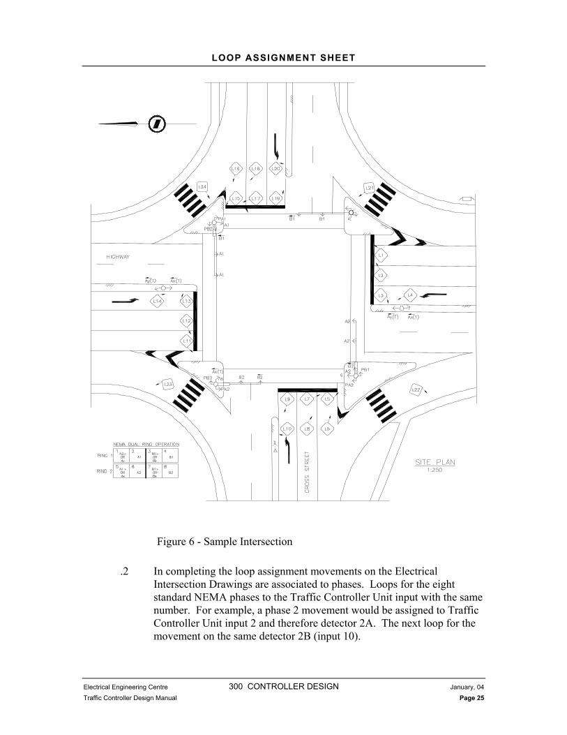
Figure 6 - Sample Intersection
.2 In completing the loop assignment movements on the Electrical Intersection Drawings are associated to phases. Loops for the eight standard NEMA phases to the Traffic Controller Unit input with the same number. For example, a phase 2 movement would be assigned to Traffic Controller Unit input 2 and therefore detector 2A. The next loop for the movement on the same detector 2B (input 10).
LOOP ASSIGNMENT SHEET
Electrical Engineering Centre 300 CONTROLLER DESIGN January, 04
Traffic Controller Design Manual Page 26
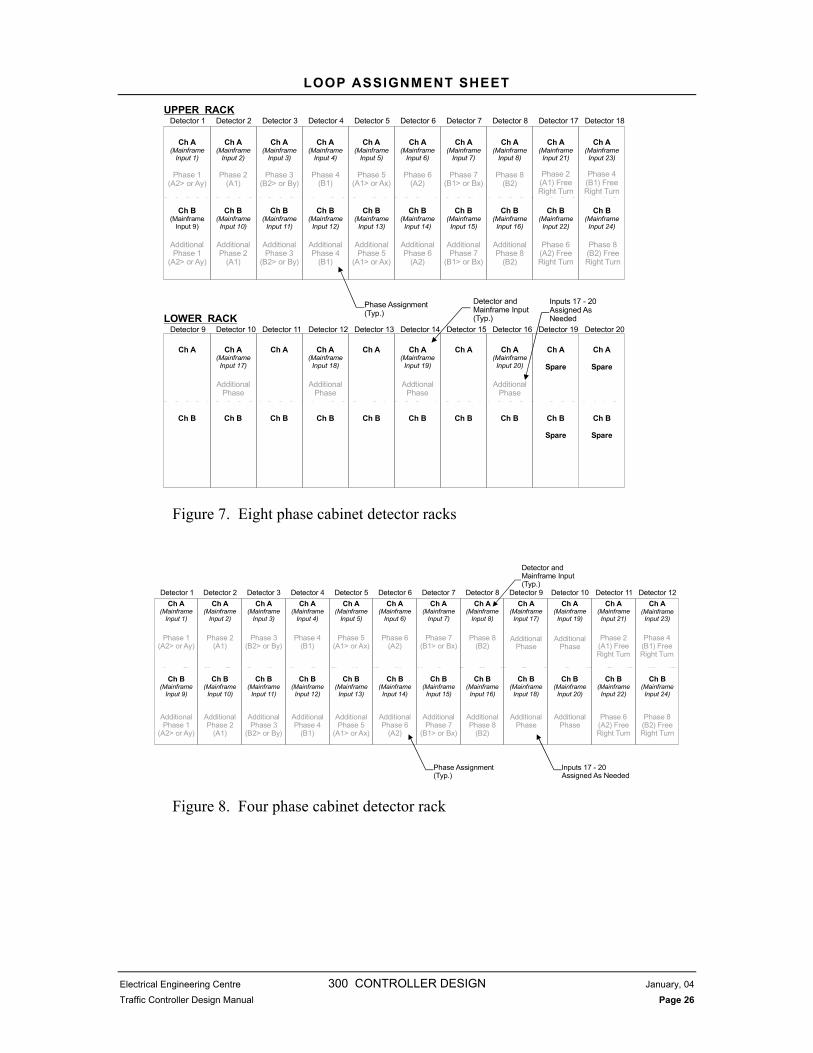
Figure 7. Eight phase cabinet detector racks
Figure 8. Four phase cabinet detector rack
Ch A(Mainframe
Input 1)
Ch B(Mainframe
Input 9)
Ch A(Mainframe
Input 2)
Ch B(MainframeInput 10)
Ch A(Mainframe
Input 3)
Ch B(Mainframe
Input 11)
Ch A(Mainframe
Input 4)
Ch B(Mainframe
Input 12)
Ch A(Mainframe
Input 5)
Ch B(Mainframe
Input 13)
Ch A(Mainframe
Input 6)
Ch B(Mainframe
Input 14)
Ch A(Mainframe
Input 7)
Ch B(MainframeInput 15)
Ch A(Mainframe
Input 8)
Ch B(MainframeInput 16)
Ch A(MainframeInput 21)
Ch B(MainframeInput 22)
Ch A(MainframeInput 23)
Ch B(MainframeInput 24)
Ch A
Ch B
Ch A(MainframeInput 17)
Ch B
Ch A
Ch B
Ch A(Mainframe
Input 18)
Ch B
Ch A
Ch B
Ch A(Mainframe
Input 19)
Ch B
Ch A
Ch B
Ch A(MainframeInput 20)
Ch A
Spare
Ch A
Spare
Ch B Ch B
Spare
Ch B
Spare
LOWER RACK
Phase 1(A2> or Ay)
Phase 2(A1)
Phase 3(B2> or By)
Phase 4(B1)
Phase 5(A1> or Ax)
Phase 6(A2)
Phase 7(B1> or Bx)
Phase 8(B2)
Phase 2(A1) FreeRight Turn
Phase 4(B1) FreeRight Turn
AdditionalPhase 1
(A2> or Ay)
AdditionalPhase 2
(A1)
AdditionalPhase 3
(B2> or By)
AdditionalPhase 4
(B1)
AdditionalPhase 5
(A1> or Ax)
AdditionalPhase 6
(A2)
AdditionalPhase 7
(B1> or Bx)
AdditionalPhase 8
(B2)
Phase 6(A2) FreeRight Turn
Phase 8(B2) FreeRight Turn
AdditionalPhase
AdditionalPhase
AddtionalPhase
AdditionalPhase
Detector andMainframe Input(Typ.)
Phase Assignment(Typ.)
Inputs 17 - 20Assigned AsNeeded
UPPER RACKDetector 1 Detector 18Detector 17Detector 8Detector 7Detector 6Detector 5Detector 4Detector 3Detector 2
Detector 9 Detector 10 Detector 11 Detector 12 Detector 13 Detector 14 Detector 15 Detector 16 Detector 19 Detector 20
Ch A(Mainframe
Input 1)
Ch B(Mainframe
Input 9)
Ch A(Mainframe
Input 2)
Ch B(Mainframe
Input 10)
Ch A(Mainframe
Input 3)
Ch B(Mainframe
Input 11)
Ch A(Mainframe
Input 4)
Ch B(MainframeInput 12)
Ch A(Mainframe
Input 5)
Ch B(MainframeInput 13)
Ch A(Mainframe
Input 6)
Ch B(MainframeInput 14)
Ch A(Mainframe
Input 7)
Ch B(Mainframe
Input 15)
Ch A(Mainframe
Input 8)
Ch B(Mainframe
Input 16)
Ch A(Mainframe
Input 17)
Ch A(MainframeInput 21)
Ch B(Mainframe
Input 18)
Ch B(MainframeInput 22)
Ch A(MainframeInput 19)
Ch A(MainframeInput 23)
Ch B(MainframeInput 20)
Ch B(MainframeInput 24)
Phase 1(A2> or Ay)
Phase 2(A1)
Phase 3(B2> or By)
Phase 4(B1)
Phase 5(A1> or Ax)
Phase 6(A2)
Phase 7(B1> or Bx)
Phase 8(B2)
AdditionalPhase
Phase 2(A1) FreeRight Turn
AdditionalPhase
Phase 4(B1) FreeRight Turn
AdditionalPhase 1
(A2> or Ay)
AdditionalPhase 2
(A1)
AdditionalPhase 3
(B2> or By)
AdditionalPhase 4
(B1)
AdditionalPhase 5
(A1> or Ax)
AdditionalPhase 6
(A2)
AdditionalPhase 7
(B1> or Bx)
AdditionalPhase 8
(B2)
AdditionalPhase
Phase 6(A2) FreeRight Turn
AdditionalPhase
Phase 8(B2) FreeRight Turn
Detector andMainframe Input(Typ.)
Phase Assignment(Typ.)
Inputs 17 - 20Assigned As Needed
Detector 1 Detector 2 Detector 3 Detector 4 Detector 5 Detector 6 Detector 7 Detector 8 Detector 9 Detector 10 Detector 11 Detector 12
LOOP ASSIGNMENT SHEET
Electrical Engineering Centre 300 CONTROLLER DESIGN January, 04
Traffic Controller Design Manual Page 27
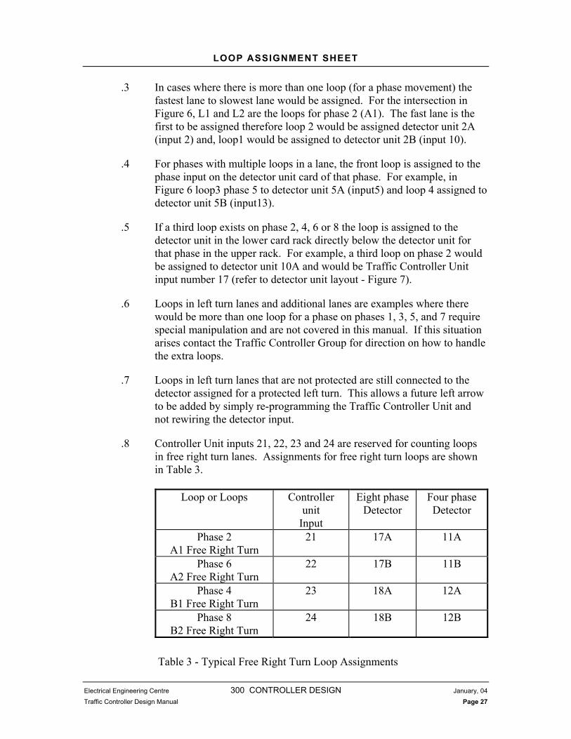
.3 In cases where there is more than one loop (for a phase movement) the fastest lane to slowest lane would be assigned. For the intersection in Figure 6, L1 and L2 are the loops for phase 2 (A1). The fast lane is the first to be assigned therefore loop 2 would be assigned detector unit 2A (input 2) and, loop1 would be assigned to detector unit 2B (input 10).
.4 For phases with multiple loops in a lane, the front loop is assigned to the phase input on the detector unit card of that phase. For example, in Figure 6 loop3 phase 5 to detector unit 5A (input5) and loop 4 assigned to detector unit 5B (input13).
.5 If a third loop exists on phase 2, 4, 6 or 8 the loop is assigned to the detector unit in the lower card rack directly below the detector unit for that phase in the upper rack. For example, a third loop on phase 2 would be assigned to detector unit 10A and would be Traffic Controller Unit input number 17 (refer to detector unit layout - Figure 7).
.6 Loops in left turn lanes and additional lanes are examples where there would be more than one loop for a phase on phases 1, 3, 5, and 7 require special manipulation and are not covered in this manual. If this situation arises contact the Traffic Controller Group for direction on how to handle the extra loops.
.7 Loops in left turn lanes that are not protected are still connected to the detector assigned for a protected left turn. This allows a future left arrow to be added by simply re-programming the Traffic Controller Unit and not rewiring the detector input.
.8 Controller Unit inputs 21, 22, 23 and 24 are reserved for counting loops in free right turn lanes. Assignments for free right turn loops are shown in Table 3.
Loop or Loops Controller unit
Input
Eight phase Detector
Four phaseDetector
Phase 2 A1 Free Right Turn
21 17A 11A
Phase 6 A2 Free Right Turn
22 17B 11B
Phase 4 B1 Free Right Turn
23 18A 12A
Phase 8 B2 Free Right Turn
24 18B 12B
Table 3 - Typical Free Right Turn Loop Assignments

LOOP ASSIGNMENT SHEET
Electrical Engineering Centre 300 CONTROLLER DESIGN January, 04
Traffic Controller Design Manual Page 28
305.6.4 Detector Unit (DU)
.1 The detector unit heading of the Loop Assignment Sheet is the detector unit card number followed by an A or B to indicate which detection channel on the card is being used. Eight phase cabinets have slots for 20 detector unit cards and four phase cabinets have slots for 12 detector uint cards. Detector card numbers are different for four phase and eight phase cabinets. Detector unit card numbers for eight and four phase cabinets are shown in Figure 7 and Figure 8.
305.6.5 Controller Unit Input (CU)
.1 The Traffic Controller Unit input heading is the units input number. The maximum number of Traffic Controller Unit inputs available for detector loops in the LMD-8000 is 24. The detector unit cards are factory pre-wired to the units input harness.
.2 The Eight phase cabinet detector unit card numbers and their corresponding Traffic Controller Unit inputs for a standard NEMA dual ring are shown in Figure 7.
.3 The four phase cabinet detector unit card numbers and their corresponding Traffic Controller Unit inputs for a standard NEMA dual ring are shown in Figure 8.
305.6.6 Movement
.1 The standard Ministry of Highways Movement designation is entered in the function column (i.e. A1, A2, B1, B1 , etc.). The symbol from Wingdings font is used to indicate a Protected Permissive Left Turn Movement.
305.6.7 Phase
.1 The traffic movement as per Signal Timing Sheet for each loop’s corresponding movement is entered in the phase column of the Loop Assignment Sheet.
305.6.8 Measure of Efficiency (MOE)
.1 Measure of efficiency is assigned for every counting loop. The phase number the loop is assigned to is entered in the MOE column. For

LOOP ASSIGNMENT SHEET
Electrical Engineering Centre 300 CONTROLLER DESIGN January, 04
Traffic Controller Design Manual Page 29
example, a loop for phase 2 that is a counting loop would have 2 entered in the MOE column. Where phase 2 is the movement to be measured.
305.6.9 Count
.1 The count function for the individual loops is assigned to ‘ON’ or ‘OFF’ for loops that count. If the loop is required to count, the word “ON” is placed in the count column. If the loop is not required to count a dash is placed in the column.
.2 The count function is assigned to ‘ON’ for highway lanes with single loops for through traffic. In dedicated left turn lanes there are 2 loops, count is assigned to ‘OFF’ for the front loop and ‘ON’ for the back loop.
.3 The count function is assigned to ‘OFF’ in the leftmost cross street lane for the front loop and “ON” for the rear loop. For cross street lanes other than the leftmost lane, count is assigned to “ON” for the front loop and “OFF” for the rear loop.
305.6.10 Mode
.1 Mode is set to the phase of opposing through traffic to the Protected Permissive left turn.
305.6.11 Delay
.1 If the loop has a delay time, enter the amount of time from the Signal Timing Sheet in this heading.
305.6.12 Stretch
.1 If the loop has a stretch time, enter the amount of time from the Signal Timing Sheet in this heading.

DRAWING SELECTION
Electrical Engineering Centre 300 CONTROLLER DESIGN January, 04
Traffic Controller Design Manual Page 30
305.7 DRAWING SELECTION
305.7.1 Selecting a Template Drawing
.1 A template drawing is selected based on the Electrical Drawings and the Signal Timing Sheet. The Traffic Controller Designer must look at the various key elements and choose a template drawing that is most similar to the project and therefore will require the least modification. The key elements to check for are Phasing, Advance Warning, and Pre-emption.
.2 Template Drawing shall be created by the EEC Traffic Controller Group to maintain consistency of traffic control product.
305.7.2 Naming Conventions
.1 Once a template drawing is selected the Traffic Controller Designer shall create a working directory following the template below:
First two letters of TE number
.2 Once the working directory is created the template drawings are copied into the working directory and renamed as follows:
Eight phase Drawings:FRONT.DWG 98001-1F.DWG REAR.DWG 98001-1R.DWG HARNESS.DWG 98001-1H.DWG
Four phase DrawingsFRONT.DWG 98001-1F.DWG HARNESS.DWG 98001-1H.DWG
*Note: 98001-1 is replaced with the TE number and sheet number (of the 1:250 site plan) for each individual project. The file name shall be limited to 8 character file names with an extension of dwg.

DRAWING MODIFICATION
Electrical Engineering Centre 300 CONTROLLER DESIGN January, 04
Traffic Controller Design Manual Page 31
305.8 DRAWING MODIFICATION
305.8.1 Title Block
Figure 9. Standard Title Block
.1 The location shall be entered as follows:
.1 All capital letters
.2 No punctuation
.3 Standard location abbreviations are as shown in Table 4.
Word Abbreviation Route RTE
At @ Road RD Street ST
Avenue AVE Boulevard BLVD
Table 4 - Standard Title Block Abbreviations
.4 A “/” is used between routes or cross streets for locations with multiple routes or cross streets.
.5 The title block location should match the Signal Timing Sheet as closely as possible.
.2 A section is provided for the signature and date of the engineer of record for this revision of the traffic controller design (not in use at this time).
.3 A section is provided to be initialled and dated by the Traffic Controller Designer, Checker and Designated Ministry Approver.

EIGHT PHASE DRAWING SHEETS
Electrical Engineering Centre 300 CONTROLLER DESIGN January, 04
Traffic Controller Design Manual Page 32
.4 A brief description of the scope of changes to the drawing is recorded in the ‘Revisions’ column.
.5 Complete all other sections of the title block such as the traffic cabinet serial number, Sheet Numbers, Site Code, Highway District, Region and Drawing Number as possible.
.6 Drawing file number shall match project TE number. The drawing Title Block shall contain the revision letter. All project documentation shall contain TE number and revision letter for project clarification.
305.9 EIGHT PHASE DRAWING SHEETS
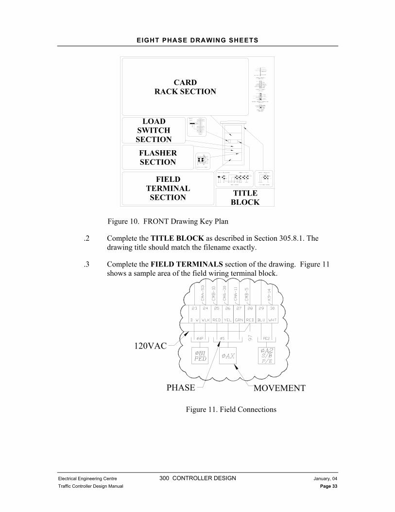
305.9.1 Front Drawing
.1 Figure 10 shows a key plan of the “FRONT” drawing. The drawing is shown in sections to outline the procedure for modifying the drawing. The drawing modifications along with the Traffic Controller Construction Document and complete working file information will assist completing Traffic Controller Cabinet Drawings.
EIGHT PHASE DRAWING SHEETS
Electrical Engineering Centre 300 CONTROLLER DESIGN January, 04
Traffic Controller Design Manual Page 33
CARDRACK SECTION
LOADSWITCH SECTION
FLASHERSECTION
FIELDTERMINALSECTION TITLE
BLOCK
Figure 10. FRONT Drawing Key Plan
.2 Complete the TITLE BLOCK as described in Section 305.8.1. The drawing title should match the filename exactly.
.3 Complete the FIELD TERMINALS section of the drawing. Figure 11 shows a sample area of the field wiring terminal block.
MOVEMENTPHASE
120VAC
Figure 11. Field Connections
EIGHT PHASE DRAWING SHEETS
Electrical Engineering Centre 300 CONTROLLER DESIGN January, 04
Traffic Controller Design Manual Page 34
.1 The drawing changes must be consistent with standards set out in the drawing template. E.g. The text, wiring drawing procedures must be in the same context as the template. Layer colour and text must comply with drawing standards. Contact EEC Traffic Controller Group for clarification if necessary.
.2 Elements of design in Field Connections section of drawing are:
.1 Field output wiring
.2 Unused reds to be satisfied wiring
.3 Intersection flash wiring
.4 Conflict monitor wiring
.5 Pre-emption wiring
.6 Any other field output wiring.
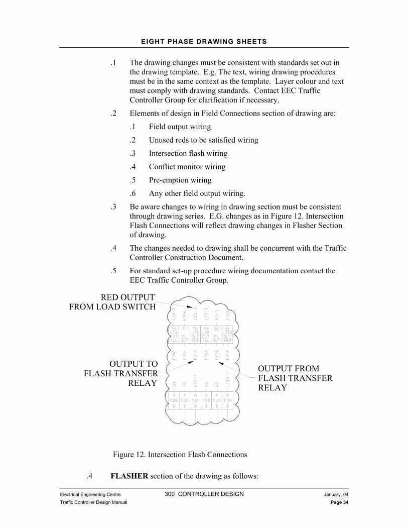
.3 Be aware changes to wiring in drawing section must be consistent through drawing series. E.G. changes as in Figure 12. Intersection Flash Connections will reflect drawing changes in Flasher Section of drawing.
.4 The changes needed to drawing shall be concurrent with the Traffic Controller Construction Document.
.5 For standard set-up procedure wiring documentation contact the EEC Traffic Controller Group.
OUTPUT FROMFLASH TRANSFERRELAY
OUTPUT TOFLASH TRANSFER
RELAY
RED OUTPUTFROM LOAD SWITCH
Figure 12. Intersection Flash Connections
.4 FLASHER section of the drawing as follows:

EIGHT PHASE DRAWING SHEETS
Electrical Engineering Centre 300 CONTROLLER DESIGN January, 04
Traffic Controller Design Manual Page 35
.1 Ensure the required Advance Warning Flashers are as per Traffic Controller Construction Document. An “X” is placed through the Advance Warning Flasher socket if it is not used as is shown in Figure 13.
ADVANCE WARNINGFLASHER (TYP.)
Figure 13. Advance Warning Flashers
.2 Ensure that all required Flash Transfer Relays have been connected, as per project Traffic Controller Construction Document. The Flash Transfer Relay section sample of the drawing is shown in Figure 14.

EIGHT PHASE DRAWING SHEETS
Electrical Engineering Centre 300 CONTROLLER DESIGN January, 04
Traffic Controller Design Manual Page 36
PHASE (TYP.)
FLASH TRANSFERRELAY (TYP.)
FIELD FLASHOUTPUT
Figure 14. Flash Transfer Relays
.3 Place an “X” through the Flash Transfer Relay corresponding to the relay that is no longer required.
.4 The changes needed to drawing shall be concurrent with the Traffic Controller Construction Document.
.5 Load Switch section
.1 Ensure all Load Switch sockets are marked corresponding to the Traffic Controller Construction Document. Showing an X as unused and clear as used socket.

EIGHT PHASE DRAWING SHEETS
Electrical Engineering Centre 300 CONTROLLER DESIGN January, 04
Traffic Controller Design Manual Page 37
.6 Complete the CARD RACK section of the front drawing. The card rack section contains the Detector Cards, Advance Warning Cards, Pre-Emption Cards And Ped/Veh Cards.
Figure 15. Detector Card Rack Wiring
.1 Ensure cards correspond to the Traffic Controller Construction Document shall have an X on connectors showing card slots not in use as in Figure 15, Figure 16 and Figure 17 showing used and unused cards as they should appear on the drawing.

EIGHT PHASE DRAWING SHEETS
Electrical Engineering Centre 300 CONTROLLER DESIGN January, 04
Traffic Controller Design Manual Page 38
CARDNUMBER
Figure 16. Advance Warning Card
.2 The Advance Warning Cards are installed based on the following channel assignments:
Card Number Channel MovementP1 1 A1
2 A2 P5 1 B1
2 B2
Table 5. Advance Warning Channel Assignments
.7 Advance Warning and Pre-empt cards that are not used must be disabled. Disabling of the Pre-Empt Cards is done with jumpers on the backboard terminals. Procedures for disabling cards are described in Table 6. Card Disable Jumpers
.8 K9 socket section
.1 Ensure changes are made as per Traffic Controller Construction Document. An X in on the socket shall indicate a relay is not in use. However be aware of usage. See EEC Traffic Controller Group standard set-up documentation.

EIGHT PHASE DRAWING SHEETS
Electrical Engineering Centre 300 CONTROLLER DESIGN January, 04
Traffic Controller Design Manual Page 39
CARDNUMBER
Figure 17. Pre-emption Card Rack Wiring
305.9.2 Rear Drawing
.1 Figure 18 shows a key plan of the “REAR” drawing. The section outlined will assist in the procedure for modifying the drawing.

EIGHT PHASE DRAWING SHEETS
Electrical Engineering Centre 300 CONTROLLER DESIGN January, 04
Traffic Controller Design Manual Page 40
Figure 18. REAR Drawing Key Plan
.2 Complete the TITLE BLOCK as described in Section 305.8.1. The drawing title should match the filename exactly.
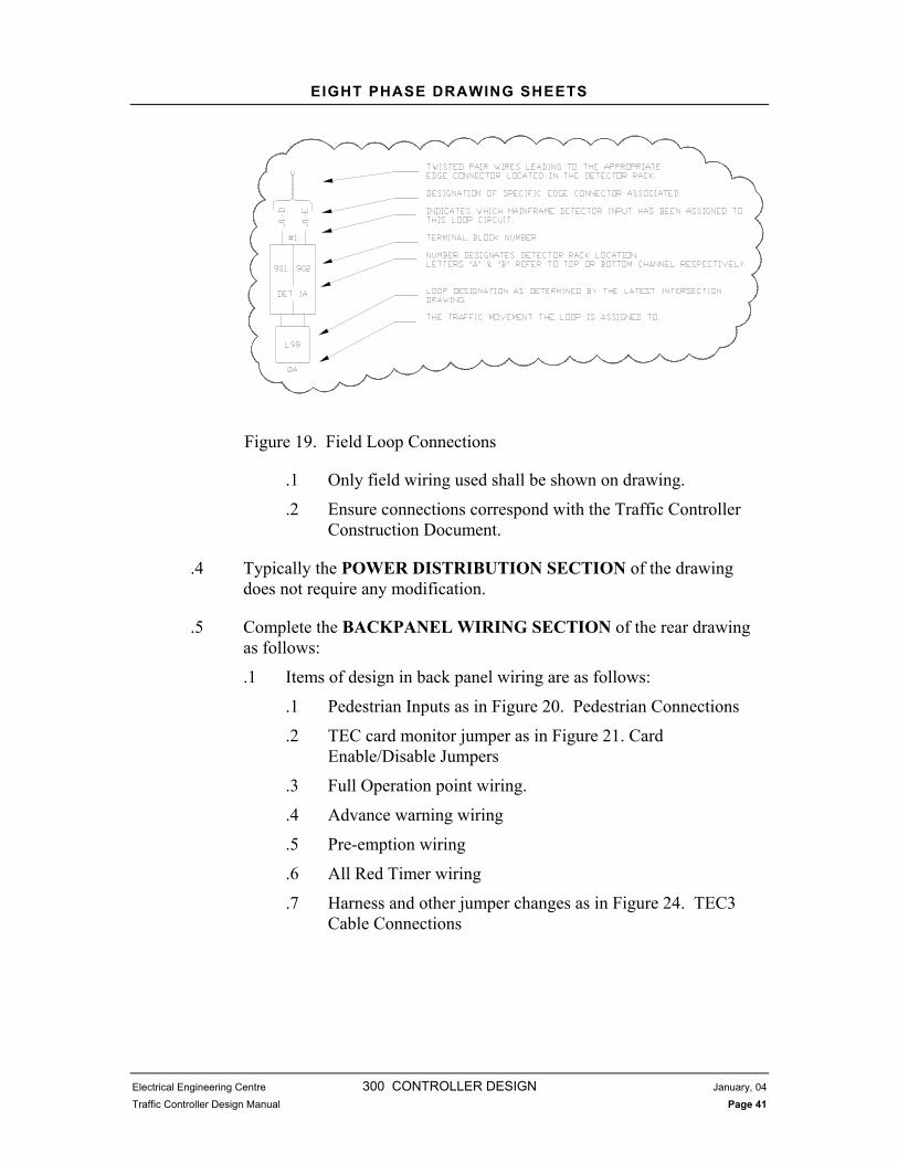
.3 Complete the FIELD LOOP CONNECTION SECTION of the rear drawing as follows:
.1 Ensure Field Loop Connections correspond to the assignments on the project Loop Assignment Sheet. Figure 19 shows the loop circuit information required to add and remove wiring for loops.
BACKPANELWIRING
SECTION
POWERDISTRIBUTION
SECTION
FIELD LOOPCONNECTION
SECTION TITLEBLOCK
EIGHT PHASE DRAWING SHEETS
Electrical Engineering Centre 300 CONTROLLER DESIGN January, 04
Traffic Controller Design Manual Page 41
Figure 19. Field Loop Connections
.1 Only field wiring used shall be shown on drawing.
.2 Ensure connections correspond with the Traffic Controller Construction Document.
.4 Typically the POWER DISTRIBUTION SECTION of the drawing does not require any modification.
.5 Complete the BACKPANEL WIRING SECTION of the rear drawing as follows:
.1 Items of design in back panel wiring are as follows:
.1 Pedestrian Inputs as in Figure 20. Pedestrian Connections
.2 TEC card monitor jumper as in Figure 21. Card Enable/Disable Jumpers
.3 Full Operation point wiring.
.4 Advance warning wiring
.5 Pre-emption wiring
.6 All Red Timer wiring
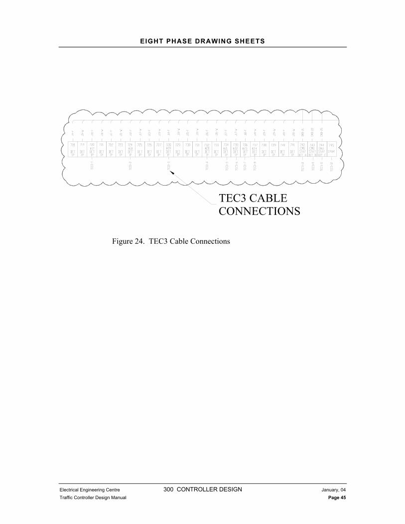
.7 Harness and other jumper changes as in Figure 24. TEC3 Cable Connections

EIGHT PHASE DRAWING SHEETS
Electrical Engineering Centre 300 CONTROLLER DESIGN January, 04
Traffic Controller Design Manual Page 42
TO PEDESTRIANPUSHBUTTON (TYP.)
Figure 20. Pedestrian Connections
CARD 3DISABLE
CARD 5DISABLE
CARD 8DISABLE
CARD 7DISABLE
Figure 21. Card Enable/Disable Jumpers

EIGHT PHASE DRAWING SHEETS
Electrical Engineering Centre 300 CONTROLLER DESIGN January, 04
Traffic Controller Design Manual Page 43
CardNumber
Disable by installing jumpers between terminals
1 243 to 244 2 244 to 245 3 245 to 246 5 246 to 247 6 247 to 248 7 248 to 249 8 249 to 250
Table 6. Card Disable Jumpers
FOP INPUT(TYP.)
Figure 22. FOP Inputs
.2 If the FOP inputs need modification it shall be concurrent with the Traffic Controller Construction Document. Standard set-up procedures document will be available with the EEC Traffic Controller Group.
.3 If the signal is required to flash all red the All Red Timer (ART) must be enabled, otherwise it is disabled. The ART is enabled by connecting terminal block 575 to logic ground as shown in Figure 23. If terminal 575 is not connected to logic ground ART is disabled.

EIGHT PHASE DRAWING SHEETS
Electrical Engineering Centre 300 CONTROLLER DESIGN January, 04
Traffic Controller Design Manual Page 44
CONNECT TO LOGICGROUND TO ENABLEALL RED TIMER
Figure 23. ART Terminal
.6 If additional detector inputs are required (i.e.more than two inputs for one phase), the TEC-3 cable inputs must be modified. The TEC-3 cable inputs that are utilised are inputs TEC3-1 to TEC3-4. These inputs are connected to the appropriate input as shown in Figure 24. TEC3 Cable Connections
.7 CSP (Communication Surge Protection wiring)
.1 Ensure wiring and drawing indications are corresponding with the Traffic Controller Construction Document. See Traffic Controller Group set-up documents for information.
EIGHT PHASE DRAWING SHEETS
Electrical Engineering Centre 300 CONTROLLER DESIGN January, 04
Traffic Controller Design Manual Page 45
TEC3 CABLECONNECTIONS
Figure 24. TEC3 Cable Connections

EIGHT PHASE DRAWING SHEETS
Electrical Engineering Centre 300 CONTROLLER DESIGN January, 04
Traffic Controller Design Manual Page 46
305.9.3 Harness Drawing
.1 Figure 25 shows a key plan of the “HARNESS” drawing. The sections outline the procedure for modifying the drawing.
TITLEBLOCK
CONFLICTMONITOR
OPTIONS
PRE-EMPTSELECTION
Figure 25. HARNESS Drawing Key Plan
.2 Complete the TITLE BLOCK as described in Section 305.8.1. The drawing title should match the filename exactly.
.3 Complete the CONFLICT MONITOR UNIT OPTIONS section of the drawing as follows:
.1 See Figure 26 as to lay out of table.
.2 The changes needed to drawing shall be concurrent with the Traffic Controller Construction Document.
.3 Contact EEC Traffic Controller Group for set-up procedures documentation.

EIGHT PHASE DRAWING SHEETS
Electrical Engineering Centre 300 CONTROLLER DESIGN January, 04
Traffic Controller Design Manual Page 47
PERMISSIVE PHASEMOVEMENT PAIRS
DIP SWITCHSETTINGS FORLNM12E
DIP SWITCHSETTING FOR
LSM12
Figure 26. Conflict Monitor Unit NEMA Plus Option Settings
.4 Note in addition to traffic movements, pre-empts must also be programmed into the Conflict Monitor Unit. Pre-empts are programmed in the same way as the regular phases, pairs of phases and pre-empt phases that are permissible are entered into the bottom section of the Conflict Monitor Unit Options Table.
.4 Complete the PRE-EMPT SELECTION section of the drawing as follows:
.1 The changes needed to drawing shall be concurrent with the Traffic Controller Construction Document.
.2 Figure 27 shows the dip switches for Pre-Empt selection.

FOUR PHASE DRAWING SHEETS
Electrical Engineering Centre 300 CONTROLLER DESIGN January, 04
Traffic Controller Design Manual Page 48
Figure 27. Pre-empt Selection Dip Switches
.3 The pre-emption dip switches are modified according to the following table 7.
.5 Complete Harness table changes concurrent with Traffic Controller Construction Document.
Bit On/Closed Off/Open Switch Function 1 CH1 Fire Mode 1 CH1 Fire Mode 2 2 CH2 Fire Mode 1 CH2 Fire Mode 2 Fire Mode Select 3 CH3 Fire Mode 1 CH3 Fire Mode 2 4 CH1 Normally Closed CH1 Normally Open 5 CH2 Normally Closed CH2 Normally Open Contact Mode Select 6 CH3 Normally Closed CH3 Normally Open 7 On/Closed 60 Seconds 8 On/Closed 7 Off/Open 90 Seconds 8 On/Closed Fire Mode 2 7 On/Closed 120 Seconds Timer Select 8 Off/Open 7 Off/Open 180 Seconds 8 Off/Open
Note: Fire Mode 1 Pulse Fire Mode 2 Hold Table 7. Pre-emption Dip Switch Setting
305.10 FOUR PHASE DRAWING SHEETS
305.10.1 Front Drawing
.1 Figure 28 shows a key plan of the “FRONT” drawing. The sections outline the procedure for modifying the drawing.
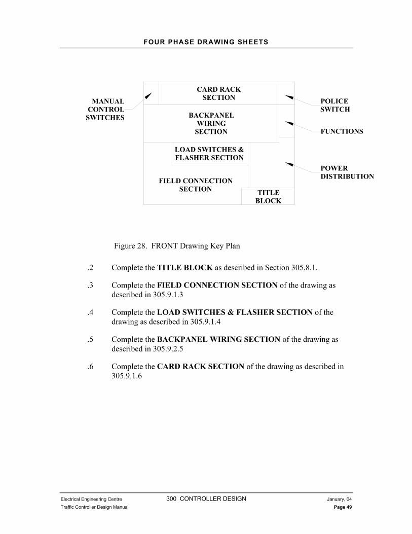
FOUR PHASE DRAWING SHEETS
Electrical Engineering Centre 300 CONTROLLER DESIGN January, 04
Traffic Controller Design Manual Page 49
TITLE BLOCK
FIELD CONNECTIONSECTION
LOAD SWITCHES & FLASHER SECTION
BACKPANELWIRING
SECTION
CARD RACKSECTIONMANUAL
CONTROLSWITCHES
POLICESWITCH
FUNCTIONS
POWERDISTRIBUTION
Figure 28. FRONT Drawing Key Plan
.2 Complete the TITLE BLOCK as described in Section 305.8.1.
.3 Complete the FIELD CONNECTION SECTION of the drawing as described in 305.9.1.3
.4 Complete the LOAD SWITCHES & FLASHER SECTION of the drawing as described in 305.9.1.4
.5 Complete the BACKPANEL WIRING SECTION of the drawing as described in 305.9.2.5
.6 Complete the CARD RACK SECTION of the drawing as described in 305.9.1.6

EEC QUALITY CONTROL CHECK
Electrical Engineering Centre 300 CONTROLLER DESIGN January, 04
Traffic Controller Design Manual Page 50
305.10.2 Harness Drawing
.1 Figure 29 shows a key plan of the “HARNESS” drawing. The sections outline the procedure for modifying the drawing.
CONFLICTMONITOR UNITOPTIONS
TITLEBLOCK
HARNESSCONNECTIONTABLES (TYP.)
Figure 29. HARNESS Drawing Key Plan
.2 Complete the TITLE BLOCK as described in Section 305.8.1.
.3 Complete the CONFLICT MONITOR UNIT OPTIONS section of the drawing as described in 305.9.3.3
.4 Complete changes to the HARNESS CONNECTION TABLES as described in 305.9.3.5
305.11 EEC QUALITY CONTROL CHECK
.1 Once the design is complete, a EEC Quality Control Check is performed by someone independent of the design process as follows:
.1 The individual utilises the EEC Quality Control Checklist contained in the Traffic Controller Construction Document to review the design.
.2 If corrections are required, the working file is returned to the Traffic Controller Designer.

TRAFFIC CONTROLLER EQUIPMENT
Electrical Engineering Centre 300 CONTROLLER DESIGN January, 04
Traffic Controller Design Manual Page 51
.3 The EEC Quality Control Checklist is signed when all deficiencies have been corrected.
305.12 TRAFFIC CONTROLLER EQUIPMENT
305.12.1 Ordering Components
.1 All components for the traffic controller are ordered from the EEC. The Traffic Controller Technician shall go through each Traffic Controller Drawings to determine quantities of required components. Depending on the type of traffic controller, the quantities are entered on the withdrawal form and sent to the stock person at the EEC. The EEC stock person will assign the ordered components to the project and ship them to the TCD. Copies of the withdrawal form are included in the Traffic Controller Construction Document located in Appendix 300B.
305.13 TRAFFIC CONTROLLER CONSTRUCTION PACKAGE
.1 The final step in the design process is to combine all the design elements into a package. The Traffic Controller Construction Package or Working file should consist of a minimum of the following:
.1 Traffic Controller Construction Document
.2 Electrical Intersection Drawings (approved and current)
.3 Signal Timing Sheet (approved and current)
.4 Traffic Engineering Check Sheet (approved and current)
.5 Traffic Controller Drawings
.6 Loop Assignment Sheet
.7 All required electrical components as listed on the withdrawal form. Consumables are not supplied as part of the Traffic Controller Construction Package. Assembly and modification of the traffic controller is covered in Section 400 and a list of required consumables is contained in Appendix 400A.

Electrical Engineering Centre 300 APPENDICES DECEMBER, 2003
Traffic Controller Design Manual
300 Appendices
Electrical Engineering Centre
Version 2.0 December 2003

Electrical Engineering Centre 300 APPENDICES DECEMBER, 2003
Traffic Controller Design Manual
APPENDICES
300A Traffic Controller Priority List
300B Traffic Controller Construction Document
300C Loop Assignment Sheets

Electrical Engineering Centre 300 APPENDICES DECEMBER, 2003
Traffic Controller Design Manual
APPENDIX 300A TRAFFIC CONTROLLER PRIORITY LIST

APPENDIX 300B TRAFFIC CONTROLLER CONSTRUCTION
DOCUMENT

PROJECT WORK ORDER ISSUED ON:
Post this order on the outside front cabinet door when the cabinet serial number has been designated.
CABINET TYPE: CABINET BUILDER:
MAINFRAME INCLUDED: CONFLICT MONITOR INCLUDED:
MODEM INCLUDED:
COMMENTS FROM PRIORITY LIST:
Project’s Documents (List of information)
Full TE- Rev. Controller cabinet used serial #: Controller cabinet template drawings used: Signal timing sheet date: Loop assignment sheet date: YY/MM/DD. Engineering checklist date:.
Project Profile (Specific information, enter the Operational reason(s) for any of the wiring & programming modifications that has to be made to complete the project.)
Phase Sequence / Operation: Example – Standard single P/P three-phase operation with advance warning. A1 =OLA ( 1+ 2) A1 = 1 (set as OL1). A2 = 2 B = 4
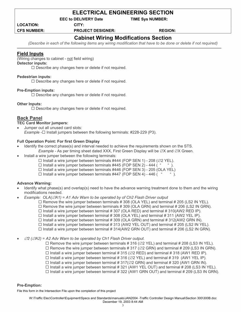
ELECTRICAL ENGINEERING SECTION EEC to DELIVERY Date TIME Sys NUMBER: LOCATION: CITY: CFS NUMBER: PROJECT DESIGNER: REGION:
File this form in the Intersection File upon the completion of this project
W:\Traffic Elec\Controller\Equipment\Specs and Standards\manuals\JAN2004 -Traffic Controller Design Manual\Section 300\300B.docDecember 19, 2003 8:44 AM
3
Cabinet Wiring Modifications Section (Describe in each of the following items any wiring modification that have to be done or delete if not required)
Field Inputs (Wiring changes to cabinet - not field wiring) Detector inputs:
Describe any changes here or delete if not required.
Pedestrian inputs: Describe any changes here or delete if not required.
Pre-Emption inputs: Describe any changes here or delete if not required.
Other Inputs: Describe any changes here or delete if not required.
Back Panel TEC Card Monitor jumpers: Jumper out all unused card slots:
Example - Install jumpers between the following terminals: #228-229 (P3).
Full Operation Point: For first Green Display Identify the correct phase(s) and interval needed to achieve the requirements shown on the STS.
Example - As per timing sheet dated XXX, First Green Display will be X and X Green. Install a wire jumper between the following terminals:
Install a wire jumper between terminals #444 (FOP SEN 1) - 208 ( 2 YEL). Install a wire jumper between terminals #445 (FOP SEN 2) - 444 ( “ “ ). Install a wire jumper between terminals #446 (FOP SEN 3) - 205 (OLA YEL) Install a wire jumper between terminals #447 (FOP SEN 4) - 446 ( “ “ ).
Advance Warning: Identify what phase(s) and overlap(s) need to have the advance warning treatment done to them and the wiring
modifications needed. Example: OLA( A1) = A1 Adv Warn to be operated by of Ch2 Flash Driver output
Remove the wire jumper between terminals # 308 (OLA YEL) and terminal # 205 (LS2 IN YEL). Remove the wire jumper between terminals # 309 (OLA GRN) and terminal # 206 (LS2 IN GRN). Install a wire jumper between terminal # 307 (OLA RED) and terminal # 310(AW2 RED IP). Install a wire jumper between terminal # 308 (OLA YEL) and terminal # 311 (AW2 YEL IP). Install a wire jumper between terminal # 309 (OLA GRN) and terminal # 312(AW2 GRN IN). Install a wire jumper between terminal # 313 (AW2 YEL OUT) and terminal # 205 (LS2 IN YEL). Install a wire jumper between terminal # 314(AW2 GRN OUT) and terminal # 206 (LS2 IN GRN).
2 ( A2) = A2 Adv Warn to be operated by Ch1 Flash Driver output. Remove the wire jumper between terminals # 316 ( 2 YEL) and terminal # 208 (LS3 IN YEL). Remove the wire jumper between terminals # 317 ( 2 GRN) and terminal # 209 (LS3 IN GRN). Install a wire jumper between terminal # 315 ( 2 RED) and terminal # 318 (AW1 RED IP). Install a wire jumper between terminal # 316 ( 2 YEL) and terminal # 319 (AW1 YEL IP). Install a wire jumper between terminal # 317( 2 GRN) and terminal # 320 (AW1 GRN IN). Install a wire jumper between terminal # 321 (AW1 YEL OUT) and terminal # 208 (LS3 IN YEL). Install a wire jumper between terminal # 322 (AW1 GRN OUT) and terminal # 209 (LS3 IN GRN).
Pre-Emption:

ELECTRICAL ENGINEERING SECTION EEC to DELIVERY Date TIME Sys NUMBER: LOCATION: CITY: CFS NUMBER: PROJECT DESIGNER: REGION:
File this form in the Intersection File upon the completion of this project
W:\Traffic Elec\Controller\Equipment\Specs and Standards\manuals\JAN2004 -Traffic Controller Design Manual\Section 300\300B.docDecember 19, 2003 8:44 AM
4
Describe the type of Pre-emption and what phase(s) Overlap(s) are to be used.
ALL RED TIMER (ART): Describe why it’s needed and how to make it operate.
Example Required due to all red flash Install a wire jumper between the terminals # 561 (ART ENABLE) and terminal #560 ( LOG GND).
Harness and other jumpers : Describe any changes here or delete if not required.
Field OutputsUsed Reds to be satisfied:
Example Install a continuous daisy-chain jumper from terminal #1 to #4 to #13 to #29.
Intersection flash: Example Intersection to flash Yellow on the Highway, Red on the Cross St.
Describe Flash condition and any changes here.
Monitor Inhibit Relay (K9) : Describe any changes here or delete if not required.
Conflict Monitor Program: List all movements and their monitoring channel number.
(PE4) Ch11 ( B1 B1 ) Ch4 Ch7 Ch6 ( A2) (PE2) Ch9 ( AX) Ch5 Ch1 ( AY) Ch10
(PE1) ( A1) Ch2 Ch3 Ch8 ( B2 B2)
Ch12 (PE5)
Solder programming card jumpers as per Harness Drawing. Set dipswitch settings as per Harness Drawing.

ELECTRICAL ENGINEERING SECTION EEC to DELIVERY Date TIME Sys NUMBER: LOCATION: CITY: CFS NUMBER: PROJECT DESIGNER: REGION:
File this form in the Intersection File upon the completion of this project
W:\Traffic Elec\Controller\Equipment\Specs and Standards\manuals\JAN2004 -Traffic Controller Design Manual\Section 300\300B.docDecember 19, 2003 8:44 AM
5
Installed Equipment Section ( Indicate in each of the following items if components are required or delete if not required)
LOOP DETECTOR CARDS: Install loop detector cards in each DET slot not crossed out on the FRONT drawing..
POWER SUPPLY (TEC-PS) : Install power supply in slot PS as shown on FRONT drawing.
ADVANCE WARNING CARD (TEC-AW2) : Install an advance warning card in slot as per FRONT DWG. Set channel one to value from the signal-timing sheet dated DD-MMM-YY.
PRE-EMPTION CARD (TEC-PE) : Install a pre-emption card in slot as per FRONT DWG. Set dipswitches as per HARNESS DWG.
PEDESTRIAN/VEHICLE CARD: Install a ped/vehicle card in slot P4.
LOAD SWITCHES: Install load switches in each LS socket not crossed out as per FRONT drawing.
FLASH CONTROL RELAY (K7) : Install relay as per FRONT DWG
FLASH TRANSFER RELAYS: Install flash transfer relays in each socket not crossed out as per FRONT drawing
SYSTEM FLASHER: Install the flasher (FL1) as shown on the FRONT drawing
ADVANCE WARNING FLASHER: Install the flasher (AWFL) as shown on the FRONT drawing.
MAINFRAME: Install with programming data as per signal timing sheet dated DD-MMM-YY.
CONFLICT MONITOR: Install with dipswitch settings as per the HARNESS DWG.
CONFLICT MONITOR COMPATIBILITY CARD: Install card with soldered jumpers as per the HARNESS DWG.
.COMMUNICATIONS :
Describe any changes here or delete if not required.
OTHER: Describe any changes here or delete if not required.

ELECTRICAL ENGINEERING SECTION EEC to DELIVERY Date TIME Sys NUMBER: LOCATION: CITY: CFS NUMBER: PROJECT DESIGNER: REGION:
File this form in the Intersection File upon the completion of this project
W:\Traffic Elec\Controller\Equipment\Specs and Standards\manuals\JAN2004 -Traffic Controller Design Manual\Section 300\300B.docDecember 19, 2003 8:44 AM
6
Drawing Modifications Section(delete the item if not required)
Update title block on all DWGs
Field Inputs Section
Loop assignments Pedestrian pushbuttons Pre-Emption Intertie
Back Panel Section
Card monitor F.O.P. Advance Warning Pre-Emption A.R.T. Harness and other jumpers.
Field output Section
Field terminals Reds to be satisfied Conflict Monitor Intersection flash Flash transfer Monitor Inhibit Relay (K9)
Harness Drawing
Conflict monitor / Program Card Harness Tables
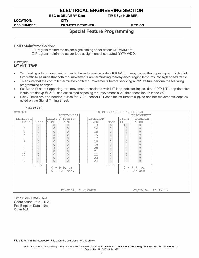
ELECTRICAL ENGINEERING SECTION EEC to DELIVERY Date TIME Sys NUMBER: LOCATION: CITY: CFS NUMBER: PROJECT DESIGNER: REGION:
File this form in the Intersection File upon the completion of this project
W:\Traffic Elec\Controller\Equipment\Specs and Standards\manuals\JAN2004 -Traffic Controller Design Manual\Section 300\300B.docDecember 19, 2003 8:44 AM
7
Special Feature Programming
LMD Mainframe Section: Program mainframe as per signal timing sheet dated: DD-MMM-YY. Program mainframe as per loop assignment sheet dated: YY/MM/DD.
Example: L/T ANTI-TRAP
Terminating a thru movement on the highway to service a Hwy P/P left turn may cause the opposing permissive left-turn traffic to assume that both thru movements are terminating thereby encouraging left-turns into high speed traffic.
To ensure that the controller terminates both thru movements before servicing a P/P left turn perform the following programming changes:
Set Mode as the opposing thru movement associated with L/T loop detector inputs. (i.e. If P/P L/T Loop detector inputs are det i/p #1 & 9 , and associated opposing thru movement is 2 then those inputs mode 2)
Delay Times are also needed, 10sec for L/T, 10sec for R/T 3sec for left turners clipping another movements loops as noted on the Signal Timing Sheet.
EXAMPLE :SYSTEM: INTERSECTION: SAMPLEFILE
DISCONNECT DISCONNECTDETECTOR DELAY / STRETCH DETECTOR DELAY / STRETCH INPUT Mode TIME TIME INPUT Mode TIME TIME 1 2 10 0 13 6 10 0 2 0 0 0 14 0 0 0 3 0 0 0 15 0 0 0 4 0 3 0 16 0 0 0 5 6 10 0 17 0 0 0 6 0 0 0 18 0 0 0 7 0 0 0 19 0 0 0 8 0 3 0 20 0 0 0 9 2 10 0 21 0 0 0 10 0 0 0 22 0 0 0 11 0 0 0 23 0 0 0 12 0 0 0 24 0 0 0 [0-9] [0-9]
0 - 9.9, or 0 - 9.9, or 0 - 127 sec. 0 - 127 sec.
F1-HELP, F8-HANGUP 07/25/94 16:19:19
Time Clock Data - N/A. Coordination Data - N/A. Pre-Emption Data –N/A Other N/A.

ELECTRICAL ENGINEERING SECTION EEC to DELIVERY Date TIME Sys NUMBER: LOCATION: CITY: CFS NUMBER: PROJECT DESIGNER: REGION:
File this form in the Intersection File upon the completion of this project
W:\Traffic Elec\Controller\Equipment\Specs and Standards\manuals\JAN2004 -Traffic Controller Design Manual\Section 300\300B.docDecember 19, 2003 8:44 AM
8
Finishing Procedures
Cover all unused spaces with blank rack mounted plates attached to rack plate holders.
Labeling
Label below each detector with the appropriate phase movement ( A, A , etc.) to which the detector is assigned.
Label below each switch pack with the appropriate phase movement ( A, A , etc.) to which the switch pack is assigned.
Label the door with the intersection name from the timing sheet, municipal name, & TE-#.
NOTE:
When construction of cabinet is complete, please notify the EEC of any errors or omissions on drawings.
For additional information contact:
Ministry of Transportation
Electrical Engineering Centre Traffic Controller Group
Mailing Address: 7818- 6Th Street Burnaby, BC V3N 4N8
Telephone: (604) 660-8200 Facsimile: (604) 660-8817

ELECTRICAL ENGINEERING SECTION EEC to DELIVERY Date TIME Sys NUMBER: LOCATION: CITY: CFS NUMBER: PROJECT DESIGNER: REGION:
File this form in the Intersection File upon the completion of this project
W:\Traffic Elec\Controller\Equipment\Specs and Standards\manuals\JAN2004 -Traffic Controller Design Manual\Section 300\300B.docDecember 19, 2003 8:44 AM
9
E.E.C. FINAL TEST - N - CHECKOUT CABINET TYPE: CABINET S/N:
MAINFRAME TYPE: S/N: SOFTWARE REV:
CONFLICT MONITOR: S/N: SOFTWARE REV:
MODEM TYPE: MODEM (Configuration):
Ref. to Traffic Controller Design Manual for Items OPERATIONAL CHECKLIST
Check Conflict Monitor Unit dipswitch settings and compatibility card as per DWG's. Ref.405.2.2 Check intersection flash. Ref.405.2.3 Check inside flash control switch. Ref.405.2.3 Check Controller Unit and Conflict Monitor Unit and other equipment for correct operation on power -up. Ref.405.2.4 Check F.O.P and (A.R.T. operation if needed) as per Signal Timing Sheet. Ref.405.2.5 Check Police Door Flash Switch. Ref.405.2.6 Check Controller unit vs. Signal Timing Sheet for programming. Ref.405.2.7 Check Advance Warning operation as per signal timing sheet. Ref.405.2.8 Check pedestrian calls to Controller Unit from field terminals. Ref.405.2.9 Check PED/VEH simulator to Controller Unit inputs. Ref.405.2.10 Check Interval Advance vs. AUTO & MANUAL setting. Ref.405.2.11 Check Pre-Emption operation in local / remote modes. Ref.405.2.12 Check vehicle calls to Controller Unit from loops via Detector Unit channels as per DWG's and LAS. Ref.405.2.13 Check Conflict Monitor Unit operation for conflict/red failures. Ref.405.2.14 Check to insure F.O.P. to control flash control circuit following manual reset of C.M.U. Ref.405.2.15 Check communications-upload and download Controller Unit via police door to PC. Ref.405.2.16 Check that components are labeled. Ref.405.2.17 Check heater and fan operation. Ref.405.2.18
Document distribution: Ref.405.2.20 Loop Assignment Sheet. - one copy each to cabinet & intersection file. (EEC?). Construction Document. - one copy each to cabinet & intersection file. (EEC?). Signal timing sheet - one copy each to cabinet & intersection file. (EEC?). Drawings distribution:Regional , two final sets, one final set laminated. (EEC?) Controller Unit Data Dump - one copy each to cabinet & intersection file.
Checked and Completed by ______________________________ Date________________

ELECTRICAL ENGINEERING SECTION EEC to DELIVERY Date TIME Sys NUMBER: LOCATION: CITY: CFS NUMBER: PROJECT DESIGNER: REGION:
File this form in the Intersection File upon the completion of this project
W:\Traffic Elec\Controller\Equipment\Specs and Standards\manuals\JAN2004 -Traffic Controller Design Manual\Section 300\300B.docDecember 19, 2003 8:44 AM
10
E.E.S QUALITY CONTROL CHECK LIST
INTERSECTION DRAWINGS
Compare signal display table to site plan. Compare loop table to site plan.
SIGNALTIMING SHEET
Compare site plan to loop assignment sheet.
Compare with signal timing sheet for:
Advance Warning Pre-Emption Fire/Railway Intersection Flash Phasing Coordination Other
LOOP ASSIGNMENT SHEET
Loop assignment sheet for accuracy Compare loops delay on signal timing sheet vs.site plan.
CABINET DRAWINGS
Title block for accuracy.
Phasing Advance warning Pre-emptionField wiring for accuracy: Loops Other
Flash transfer relays
Field output terminals
Advance warning flashers Pre-Emption
Load switches K9 relay Flash transfer relays
Intersection flash wiring correct ID:
TEC cards Power Supply Advance Warning
TEC card monitor wiring
F.O.P.wiring A.R.T. wiring Advance warning wiring Other wiring for accuracy: Pre-Emption
wiring C.M.U. setup detail
Communication cables wiring
DOCUMENTS
Compare construction document to controller drawings. Compare LMD data-dump to signal timing sheet and loop assignment sheet.
CST Prepared by: ______________________________ Date________________
Quality control completed by: ___________________________ Date________________

ELECTRICAL ENGINEERING SECTION EEC to DELIVERY Date TIME Sys NUMBER: LOCATION: CITY: CFS NUMBER: PROJECT DESIGNER: REGION:
File this form in the Intersection File upon the completion of this project
W:\Traffic Elec\Controller\Equipment\Specs and Standards\manuals\JAN2004 -Traffic Controller Design Manual\Section 300\300B.docDecember 19, 2003 8:44 AM
11
WITHDRAWAL PREPAID OLD CFS #Manufacturer Stock Code Description Quantity
CABINETSSIGMA S7 8 Phase Base Mounted Cabinet (S7)SIGMA M3 4 Phase Base Mounted Cabinet (M3)
MAINFRAMES TCT LMD Controller Unit (LMD 8000)TCT MDM On Street Master (MDM 100)
CONFLICT MONITORS TCT LNM12E 12 Channel CMU ( With Event Logging)TCT LSM12 12 Channel CMU (No Event Logging)TCT Compatibility program card
LOOP DETECTORS SARA GP6C 2 Channel rack mounted (222)RENO MOD C 2 Channel rack mounted (LCD 222)
EDI ORA2 2 Channel rack mounted (LCD 222)
INPUT MODIFIER CARDS TEC PS Power supply (TEC-PS)ES DPE3 Pre-empt Interface Card (TEC-PE)ES AW2 Advance Warning Card (TEC-AW)ES RIC Relay Interface Card (TEC-RIC)ES PV4 Pedestrian\Vehicle Card (TEC-PV4)ES PV8 Pedestrian\Vehicle Card (TEC-PV8)
LOAD SWITCHES ES 200 NEMA Load Switch PackES 204 NEMA Double Pole FlasherES AW-2 Advance Warning Flasher
RELAYS & TIMERS P&B FCR Flash Control Relay
MIDTEX FTR Flash Transfer RelayP&B K9 24v DC 4 pole Double Throw Relay
PHOENIX TBR1 24v DC 1 pole Double Throw RelayPHOENIX TBR2 24v DC 2 pole Double throw Relay
GE LM90M GE Programmable Logic Controller
COMMUNICATIONS USR MODEM 33.6k baud Modem
CABLESCAB TEC 1 Tec 1 (Computer to Mainframe)CAB TEC2 Tec 2 (RS232 - 25’ extension)CAB TEC 3 Tec 3 (Detector input)CAB TEC 4 Tec 4 (Police door extension)CAB TEC 5 Tec 5 (Modem to Mainframe)CAB TEC 6 Tec 6 (MDM 100 to Modem)CAB TEC 7 Tec 7 (Conflict Monitor to Mainframe)
SUNDRIESWIHARD SDINS 8 phase drop-in packWIHARD MDINS 4 phase drop-in pack
ASM CDP Rack Plate HoldersASM CDP1 Single Rack PlatesASM CDP10 Ten Rack PlateASM CDP2 Double Rack Plates
BRUNDY KPA8C Field Terminal Screw Lugs

Electrical Engineering Centre 300 APPENDICES DECEMBER, 2003
Traffic Controller Design Manual
APPENDIX 300C LOOP ASSIGNMENT SHEETS
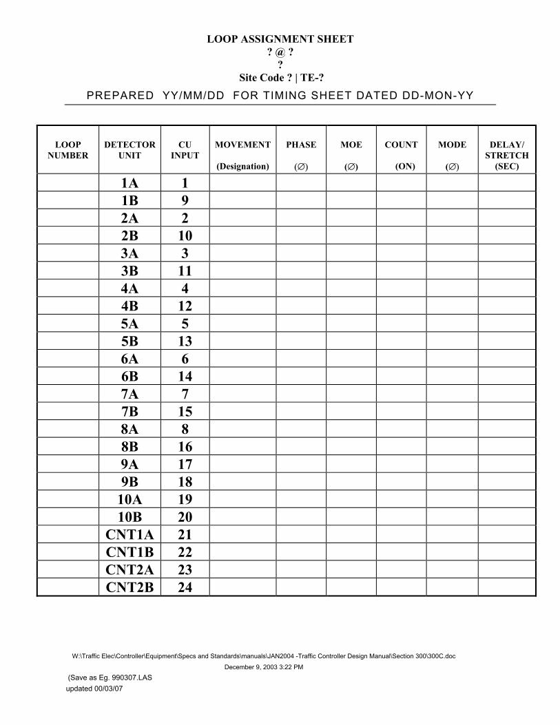
LOOP ASSIGNMENT SHEET ? @ ?
? Site Code ? | TE-?
PREPARED YY/MM/DD FOR TIMING SHEET DATED DD-MON-YY
W:\Traffic Elec\Controller\Equipment\Specs and Standards\manuals\JAN2004 -Traffic Controller Design Manual\Section 300\300C.doc
December 9, 2003 3:22 PM
(Save as Eg. 990307.LAS updated 00/03/07
LOOPNUMBER
DETECTORUNIT
CUINPUT
MOVEMENT
(Designation)
PHASE MOE
( )
COUNT
(ON)
MODE
(
DELAY/STRETCH
(SEC)
1A 1 1B 9 2A 2 2B 10 3A 3 3B 11 4A 4 4B 12 5A 5 5B 13 6A 6 6B 14 7A 7 7B 15 8A 8 8B 16 9A 17 9B 18 10A 19 10B 20 CNT1A 21 CNT1B 22 CNT2A 23 CNT2B 24

LOOP ASSIGNMENT SHEET ? @ ?
? Site Code ? | TE-?
PREPARED YY/MM/DD FOR TIMING SHEET DATED DD-MON-YY
W:\Traffic Elec\Controller\Equipment\Specs and Standards\manuals\JAN2004 -Traffic Controller Design Manual\Section 300\300C.doc
December 9, 2003 3:22 PM
(Save as Eg. 990307.LAS updated 00/03/07
LOOPNUMBER
DETECTORUNIT
CUINPUT
MOVEMENT
(Designation)
PHASE MOE
( )
COUNT
(ON)
MODE
(
DELAY/STRETCH
(SEC)
1A 1 1B 9 2A 2 2B 10 3A 3 3B 11 4A 4 4B 12 5A 5 5B 13 6A 6 6B 14 7A 7 7B 15 8A 8 8B 16 9A 9B 10A 17 10B 11A 11B 12A 18 12B

LOOP ASSIGNMENT SHEET ? @ ?
? Site Code ? | TE-?
PREPARED YY/MM/DD FOR TIMING SHEET DATED DD-MON-YY
W:\Traffic Elec\Controller\Equipment\Specs and Standards\manuals\JAN2004 -Traffic Controller Design Manual\Section 300\300C.doc
December 9, 2003 3:22 PM
(Save as Eg. 990307.LAS updated 00/03/07
LOOPNUMBER
DETECTORUNIT
CUINPUT
MOVEMENT
(Designation)
PHASE
( )
MOE
( )
COUNT
(ON)
MODE
( )
DELAY/STRETCH
(SEC)
13A 13B 14A 19 14B 15A 15B 16A 20 16B
CNT 1A 21 CNT 1B 22 CNT 2A 23 CNT 2B 24 CNT 3A CNT 3B CNT 4A CNT 4B

Section 400 TRAFFIC CONTROLLER CABINET
ASSEMBLY AND TESTING
Electrical Engineering Centre
Version 2.0 January 2004

TABLE OF CONTENTS
Electrical Engineering Centre 400 CONTROLLER CONSTRUCTION January 8 2004
Traffic Controller Design Manual Page i
400 TRAFFIC CONTROLLER CABINET CONSTRUCTION, ASSEMBLY AND TESTING
401 INTRODUCTION................................................................................................... 1 401.1.1 Section Summary ..............................................................................1 401.1.2 Prerequisites......................................................................................1
402 ASSEMBLY AND MODIFICATION ...................................................................... 3 402.1.1 Traffic Controller Cabinet Orientation................................................3
402.2 WIRING MODIFICATIONS AND EQUIPMENT INSTALLATION........................5 402.2.1 Construction Methods........................................................................5 402.2.2 General ..............................................................................................5 402.2.3 Four and Eight Phase Cabinets ........................................................6
403 FINISHING PROCEDURES.................................................................................. 9
403.1 LABELLING .........................................................................................................9 403.1.1 Labelling Standards...........................................................................9 403.1.2 Location and Drawing Number..........................................................9 403.1.3 Pre-emption Cards ..........................................................................11 403.1.4 Detector Unit Cards .........................................................................12 403.1.5 Load Switches .................................................................................13 403.1.6 Unused Sockets ..............................................................................14
404 TRAFFIC CONTROLLER UNIT PROGRAMMING............................................. 15
405 TESTING............................................................................................................. 16
405.1 INTRODUCTION ...............................................................................................16
405.2 E.E.S FINAL TEST-N-CHECKOUT FORM .......................................................16 405.2.1 General ............................................................................................16 405.2.2 Conflict Monitor Unit ........................................................................16 405.2.3 Intersection Flash / Inside flash control switch. ...............................16 405.2.4 Controller Unit and Conflict Monitor Unit Display ............................17 405.2.5 Full Operation Point (FOP) ..............................................................17 405.2.6 Police Door Switch ..........................................................................18405.2.7 Controller Unit Programming...........................................................18 405.2.8 Advance Warning ............................................................................18 405.2.9 Pedestrian Calls ..............................................................................18 405.2.10 PED/VEH Simulator.........................................................................19 405.2.11 Manual Control Switch and Interval Advance Pushbutton .............19

TABLE OF CONTENTS
Electrical Engineering Centre 400 CONTROLLER CONSTRUCTION January 8 2004
Traffic Controller Design Manual Page ii
405.2.12 Pre-emption .....................................................................................19 405.2.13 Detector Unit Inputs.........................................................................20 405.2.14 Conflict Monitor Unit ........................................................................20 405.2.15 Flash control Circuit.........................................................................20 405.2.16 Traffic Controller Unit Communications Ports .................................20 405.2.17 Labelling ..........................................................................................20 405.2.18 Heater and Fan................................................................................21 405.2.19 General Operation Checks..............................................................21 405.2.20 Documentation.................................................................................22 405.2.21 Design Changes During Assembly, Construction and Testing .......22
405.3 SIGNING............................................................................................................22
Electrical Engineering Centre 400 CONTROLLER CONSTRUCTION January 8 2004
Traffic Controller Design Manual Page 1
401 INTRODUCTION
401.1.1 Section Summary
.1 This section describes the process and methods used to assemble, modify, program and test a traffic controller cabinet. This process produces a fully functional and tested traffic controller cabinet ready for field installation in an intersection.
401.1.2 Prerequisites
.1 A construction package will be sent to the assigned Traffic Controller Assembler from the Traffic Controller Designer. The Project package includes the following:
.1 Traffic Controller Construction Document including the following:
.1 Traffic Controller Construction Order
.2 Wiring Modifications
.3 Installed Equipment
.4 Drawing Modifications
.5 Special Program Features
.6 Finishing Procedures
.7 E.E.C. Final Test-N-Checkout form
.8 E.E.C. Quality Control Check List
.9 Withdrawal Form
.2 Current Electrical intersection drawings (signed by a professional engineer)
.3 Current Signal Timing Sheet (signed by a professional engineer)
.4 Traffic Controller Drawings
.5 Loop Assignment Sheet
.6 All required electrical components as listed on the withdrawal form.
.7 Consumables are not supplied as part of the construction package. A list of required consumables is contained in Appendix 400A.

WIRING MODIFICATIONS AND EQUIPMENT INSTALLATION
Electrical Engineering Centre 400 CONTROLLER CONSTRUCTION January 8 2004
Traffic Controller Design Manual Page 2
.8 A sample Traffic Controller Construction Package is included in Appendix 400B.

Electrical Engineering Centre 400 CONTROLLER CONSTRUCTION January 8 2004
Traffic Controller Design Manual Page 3
402 ASSEMBLY AND MODIFICATION
402.1.1 Traffic Controller Cabinet Orientation
.1 The Traffic Controller Assembler must become familiar with the locations of equipment within the traffic controller cabinet.
.2 Typical traffic controller cabinet assembly layouts are shown in Figure 2 through Figure 1.
FLASHER ANDLOAD SWITCHSECTION
CONTROLLER UNIT,CONFLICT MONITOR UNITAND MODEM
FIELD TERMINALSECTION
POWER DISTRIBUTIONASSEMBLY (SIDE OFCABINET)
BACKPANELWIRING SECTION
CARD RACKSECTION
DETECTOR, PRE-EMPTAND PEDESTRIAN
FIELD INPUTCONNECTION SECTION
(SIDE OF CABINET)
Figure 1. Layout for a Four Phase Cabinet

WIRING MODIFICATIONS AND EQUIPMENT INSTALLATION
Electrical Engineering Centre 400 CONTROLLER CONSTRUCTION January 8 2004
Traffic Controller Design Manual Page 4
CARD RACKSECTION
FIELD TERMINALSECTION
FLASHERSECTION
CONFLICTMONITOR UNITCONTROLLER UNIT
MODEM (REAR)
LOAD SWITCHSECTION
Figure 2. Front Layout of an Eight Phase Cabinet
BACKPANELWIRING SECTION
DETECTOR INPUTCONNECTION
SECTION
POWERDISTRIBUTIONSECTION
CONTROLLER UNITCONFLICTMONITOR UNIT
MODEM
PRE-EMPT ANDPEDESTRIAN INPUTCONNECTION SECTION
Figure 3. Rear Layout for an Eight-Phase Cabinet

WIRING MODIFICATIONS AND EQUIPMENT INSTALLATION
Electrical Engineering Centre 400 CONTROLLER CONSTRUCTION January 8 2004
Traffic Controller Design Manual Page 5
402.2 WIRING MODIFICATIONS AND EQUIPMENT INSTALLATION
402.2.1 Construction Methods
402.2.2 General
.1 All wiring shall be completed in a neat and organised manner.
.2 Wire shall be bundled in with existing harnesses. Wires shall be bundled using a single tie method where possible.
.3 Any unused wire ends shall be bundled and covered in heat shrink.
.4 Crimp-on connectors shall be attached using a proper ratchet crimp tool.
.5 Check that all terminal block connections are tight.
.6 Solder and heat shrink diode connections and wire extensions as described below and as shown in Figure 4.
.1 Bind and solder wire to the diode.
.2 Heat shrink, exposed leads and solder joint covering all metal but leaving the diode body exposed so the direction can be verified.
SOLDER JOINT
DIODE BIND JOINT W ITHBARE FINE W IRE
COVER JOINT W ITHHEAT SHRINK
HEAT SHRINK
Figure 4. Diode Solder Connection

WIRING MODIFICATIONS AND EQUIPMENT INSTALLATION
Electrical Engineering Centre 400 CONTROLLER CONSTRUCTION January 8 2004
Traffic Controller Design Manual Page 6
402.2.3 Four and Eight Phase Cabinets
.1 Modifications are completed on one section of the traffic controller cabinet at a time following the Traffic Controller Construction Document and Traffic Controller Drawings.
.2 Traffic Controller Cabinet – Wiring Modifications
.1 Power Distribution Section
.1 Typically no wiring changes are required unless otherwise noted.
.2 Field Output Section
.1 Installation of reds to be satisfied jumpers shall use red #14 AWG wire.
.2 Make wiring modifications for intersection flash requirements as noted.
.3 Install field terminal lugs as required on four phase traffic controller cabinets. A list of required consumables is contained in Appendix 400A.
.3 Backpanel Wiring Section
.1 Jumper wire shall be of #22 AWG stranded.
.2 Install CARD/MON and CARD jumpers as noted. Approved tie bars shall be used as noted in consumables list contained in Appendix 400A.
.3 Install full operation point jumpers as noted.
.4 Install or remove the ART jumper as noted.
.5 Install wiring modifications for advance warning, pre-emption and harness connections as noted.
.6 Make wiring changes to the TEC-3 cable connection points as noted.
.7 Install TEC6 cable (Traffic Controller Unit to terminal blocks).
.4 Field Loop Connections Section
.1 Typically no wiring changes are required unless otherwise noted.
WIRING MODIFICATIONS AND EQUIPMENT INSTALLATION
Electrical Engineering Centre 400 CONTROLLER CONSTRUCTION January 8 2004
Traffic Controller Design Manual Page 7
.3 Traffic Controller Cabinet – Equipment Installation
.1 Flasher Section
.1 Install Flash Transfer Relays, Flash Control Relay, Advance Warning Flashers and Intersection Flasher as noted.
.2 Check that the flash frequency switch on the front on the intersection flasher is set at 60 hertz.
.2 Load Switch Section
.1 Install load switches as noted.
.3 Card Rack Section
.1 Install PED/VEH, Pre-Emption, Advance Warning and Detector Unit Cards as noted.
.4 Power Supply Section
.1 Install TEC-PS power supply.
.5 Communications
.1 Install modem and connect TEC5 (Traffic Controller unit to modem) if required.
.2 Install Communications Surge Protector (CSP) if required.
.6 Conflict Monitor Unit
.1 Install Conflict Monitor Unit in cabinet.
.2 Set Conflict Monitor Unit dipswitches as per Traffic Controller Drawing.
.3 If a program card is required, install compatibility jumpers on the Program Card as noted. Solder jumpers from both sides of the card to ensure proper connection with all traces.Jumper wire shall be as specified in consumables list Appendix 400A
.4 The Program Card is programmed specifically for each intersection and shall stay with the traffic controller cabinet even when the Conflict Monitor Unit is replace.
.5 Secure the program card to the MS harness as follows. Drill a 1/8” hole in the bottom outside corner of the card. Use #22 AWG stranded wire as a lanyard. Attach the card to the harness through the hole in the card and the harness connector.

WIRING MODIFICATIONS AND EQUIPMENT INSTALLATION
Electrical Engineering Centre 400 CONTROLLER CONSTRUCTION January 8 2004
Traffic Controller Design Manual Page 8
.4 Blanking Plates
.1 Install blanking plates in any unused detector and/or input card slots. Blanking plates require slider plates to secure them in place. Requirements for blanking plates and slider plates are as follows:
.1 Single Space – 1 blanking plate, 1 slider plate
.2 Double Space – 1 double blanking plate, 1 slider plate
.3 Ten Spaces – 10 space blanking plate, 2 slider plates
.5 Technical operation specifications for traffic controller components are located in the Traffic Controller Cabinet Manual.

Electrical Engineering Centre 400 CONTROLLER CONSTRUCTION January 8 2004
Traffic Controller Design Manual Page 9
403 FINISHING PROCEDURES
403.1 LABELLING
403.1.1 Labelling Standards
.1 All labelling shall be adhesive tape with black lettering on a white background. Lettering shall be a minimum of 5mm high and shall be as shown in the following sections. Labels shall not be hand-written.
.2 Labels for card racks shall be continuous where possible.
.3 Labelling shall be done with a Brother PT-PC computer labeller or approved equivalent.
.4 Samples of labelling locations shall be followed as near as possible.
403.1.2 Location and Drawing Number
.1 The location, city, drawing number and site code shall be labelled with 20mm tape on the inside of all doors as shown in Figure 5.
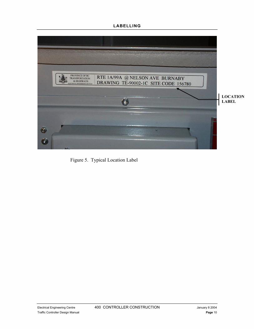
LABELLING
Electrical Engineering Centre 400 CONTROLLER CONSTRUCTION January 8 2004
Traffic Controller Design Manual Page 10
Figure 5. Typical Location Label
LOCATIONLABEL

LABELLING
Electrical Engineering Centre 400 CONTROLLER CONSTRUCTION January 8 2004
Traffic Controller Design Manual Page 11
403.1.3 Pre-emption Cards
.1 Label the pre-emption card with 20mm tape as shown in Figure 6.
Figure 6. Typical Pre-emption Card Label
PRE-EMPTORINTERFACE CARD LABEL
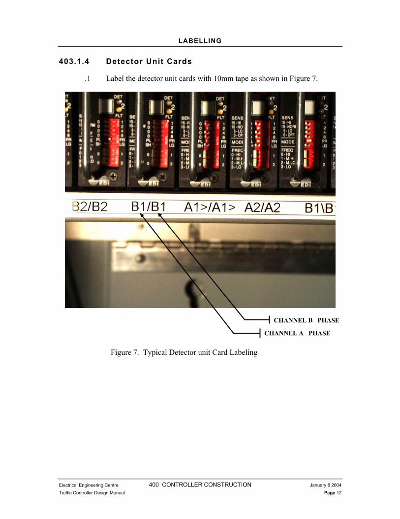
LABELLING
Electrical Engineering Centre 400 CONTROLLER CONSTRUCTION January 8 2004
Traffic Controller Design Manual Page 12
403.1.4 Detector Unit Cards
.1 Label the detector unit cards with 10mm tape as shown in Figure 7.
Figure 7. Typical Detector unit Card Labeling
CHANNEL B PHASE
CHANNEL A PHASE
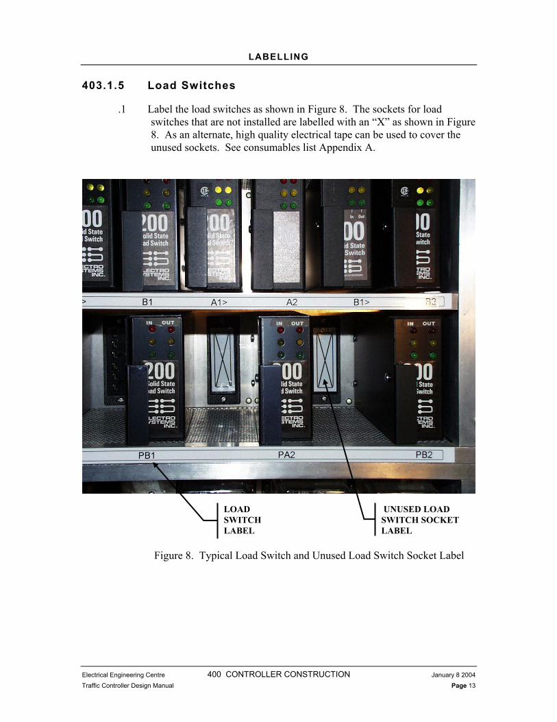
LABELLING
Electrical Engineering Centre 400 CONTROLLER CONSTRUCTION January 8 2004
Traffic Controller Design Manual Page 13
403.1.5 Load Switches
.1 Label the load switches as shown in Figure 8. The sockets for load switches that are not installed are labelled with an “X” as shown in Figure 8. As an alternate, high quality electrical tape can be used to cover the unused sockets. See consumables list Appendix A.
Figure 8. Typical Load Switch and Unused Load Switch Socket Label
LOADSWITCHLABEL
UNUSED LOAD SWITCH SOCKET LABEL

LABELLING
Electrical Engineering Centre 400 CONTROLLER CONSTRUCTION January 8 2004
Traffic Controller Design Manual Page 14
403.1.6 Unused Sockets
.1 Sockets for equipment that is not installed are labelled with an “X” as shown in Figure 9. As an alternate, high quality electrical tape can be used to cover the unused sockets. See consumables list Appendix A.
Figure 9. Typical Unused Relay Socket Label
UNUSED SOCKET LABEL

Electrical Engineering Centre 400 CONTROLLER CONSTRUCTION January 8 2004
Traffic Controller Design Manual Page 15
404 TRAFFIC CONTROLLER UNIT PROGRAMMING
.1 Programming of the Traffic Controller Unit is not covered in this manual. Refer to the LMD 8000 Programming Manual and the Electrical Engineering Centre LMD 8000 Programming Guide for detailed programming information.
.2 Implement Traffic Controller Unit special program features. (refer to Traffic Controller Construction Document)
.3 Once programming is complete, produce a Controller Unit Program Data Capture using the TCCSS program (available from EEC). Instructions for using the TCCSS software are contained in Appendix 400C. The Controller Unit Program Data Capture produced must be from the Traffic Controller Unit that is to be installed in the traffic controller cabinet.
.4 A peer review of the program must be completed before installation.
.5 Install the Traffic Controller Unit in the cabinet and record installation. A Traffic Signal Record Form must be faxed to the Regional Traffic Engineer, EEC and the MES. This form is included in Appendix 600A

Electrical Engineering Centre 400 CONTROLLER CONSTRUCTION January 8 2004
Traffic Controller Design Manual Page 16
405 TESTING
405.1 INTRODUCTION
.1 When the traffic controller assembly and/or modification is complete, the Traffic Controller Assembler shall test the traffic controller cabinet and Traffic Controller Unit. Procedures for testing the traffic controller cabinet and Traffic Controller Unit are described in the following sections.
405.2 E.E.C. FINAL TEST-N-CHECKOUT FORM
405.2.1 General
.1 A light board to simulate each of the traffic movements in an intersection shall be connected to the field terminals of the cabinet in order to complete the traffic controller cabinet test.
.2 The following sections contain instructions for completing the E.E.C. Final Test-n-Checkout Form contained in the Traffic Controller Construction Document. The form is a series of operational checks to check the traffic controller is wired correctly and operating properly. A sample of the form is contained in the Traffic Controller Construction Document in Appendix 300C.
405.2.2 Conflict Monitor Unit
.1 Check Conflict Monitor Unit settings and compatibility card as per project cabinet drawings.
405.2.3 Intersection Flash / Inside flash control switch.
.1 With the main breaker on and all other breakers and switches in the “off” or “flash” positions, check that when power is applied to the cabinet the intersection flashes according to the Signal Timing Sheet.
.2 With all breakers in the “on” position, move the inside flash switch from “flash” to “3 colour”. Check that all components power up and the

E.E.C. FINAL TEST-N-CHECKOUT FORM
Electrical Engineering Centre 400 CONTROLLER CONSTRUCTION January 8 2004
Traffic Controller Design Manual Page 17
“INB” LED on the PED/VEH card is on. Check that the Traffic Controller Unit is cycling and the intersection is still in flash.
.3 Move the police switch from the “flash” to the “3 colour” position. Check that the “INH” LED on the PED/VEH card turns off. The Traffic Controller Unit will cycle until the “FOP” LED comes on, the “EN” LED will come on and the intersection will go from flash to 3-colour operation.
.4 Check that the Advance Warning Flashers are on when the intersection is in flashing operation.
405.2.4 Controller Unit and Conflict Monitor Unit Display
.1 Checking operation of Controller unit and the Conflict Monitor Unit as displays cycle through operation as designed
405.2.5 Full Operation Point (FOP)
.1 The full operation point refers to the point in time when certain conditions are met and the Traffic Controller changes from flashing operation to three colour operation.
.2 There are four FOP inputs to the ELB section of the PED/VEH card that must be true before the traffic controller cabinet will switch from flashing operation to three colour operation.
.3 Test the full operation point by taking the intersection in and out of flash and checking that the traffic controller cabinet switches from flash to three colour operation correctly and at the proper point in the sequence.This test shall be done from a full shut down point.
.4 Check the full operation point indicating light on the PED/VEH card to ensure that it is operating correctly. The FOP LED should be on when the FOP inputs are true.
.5 All Red Timer (ART) operation in correct manner as per Signal Timing Sheet.
.1 If the signal flashes all red, check that the All Red Timer is applied and the first red interval is held for its allotted time plus 3 seconds. If the signal does not flash all red, the All Red Timer does not apply. As note in Traffic Controller Construction Document.

Electrical Engineering Centre 400 CONTROLLER CONSTRUCTION January 8 2004
Traffic Controller Design Manual Page 18
405.2.6 Police Door Switch
.1 Check operation of police door switch.
405.2.7 Controller Unit Programming
.1 Check Traffic Controller Unit verses Signal Timing Sheet and Loop Assignment Sheet for unit to be programmed correctly for project.
.2 A peer review of any program changes to a Controller Unit shall be done.
.1 The review shall consist of a Controller Unit Program Data Capture obtained from the unit to be installed in the field. The Controller Unit Program Data Capture and the Controller Unit shall be installed in the field as a unit.
405.2.8 Advance Warning
.1 Check that the advance warning field outputs are enabled with the correct phases.
.2 Check that advance warning pre-termination intervals are correct as stated on the Signal Timing Sheet.
.3 Check that LED’s on Advance Warning Cards are on when advance warning is on.
.4 Check that the cascading function is operating correctly (if used).
405.2.9 Pedestrian Calls
.1 All pedestrian inputs to Traffic Controller Unit shall be tested.
.2 Check the PED/VEH card to Traffic Controller Unit connections by pushing the pedestrian test buttons on the PED/VEH card and ensuring the correct Traffic Controller Unit input is actuated and the phase is serviced.
.3 Simulate pedestrian calls by placing a jumper between the two field terminals for each pedestrian pushbutton. Check that the correct Traffic Controller Unit input is actuated.

Electrical Engineering Centre 400 CONTROLLER CONSTRUCTION January 8 2004
Traffic Controller Design Manual Page 19
405.2.10 PED/VEH Simulator
.1 Check the PED/VEH card pedestrian and vehicle inputs by pushing the test buttons on the PED/VEH card and ensuring the correct Traffic Controller Unit input is actuated and the phase is serviced.
405.2.11 Manual Control Switch and Interval Advance Pushbutton
.1 The manual switch is normally in the “AUTO” position.
.2 Check that the Traffic Controller Unit stops cycling once the auto/manual control switch is in the “MANUAL” position.
.3 With the manual control switch in the “MANUAL” position, check that the Traffic Controller Unit steps through the Traffic Controller Units cycle as the Interval Advance Pushbutton is depressed then released.Check that the yellow and red clearance times are preserved. Check that the Traffic Controller Unit displays “MANUAL CONTROL ENABLE” and “INTERVAL ADVANCE” on the status screen.
405.2.12 Pre-emption
.1 Ensure dipswitches on the TEC-DPE3 pre-emptor card are set according to the Traffic Controller Drawings.
.2 Check the local and remote pre-emption pushbutton operation as follows:
.1 Move the local/remote switch to the local position.
.2 Push the test button.
.3 Check that the proper Traffic Controller Unit pre-empt input is actuated.
.4 Check that the Traffic Controller Unit executes the correct sequence of pre-emption as per the Signal Timing Sheet and LMD Programming Guide.
.5 Check any field indications as required.
.6 Move the local/remote switch to the “REMOTE” position.
.7 Push the test button.
.8 Check that the proper Traffic Controller Unit pre-empt input is actuated.
.3 Field Terminals:

Electrical Engineering Centre 400 CONTROLLER CONSTRUCTION January 8 2004
Traffic Controller Design Manual Page 20
.1 Install a jumper in the pre-empt field terminals.
.2 Switch the local/remote switch to the “REMOTE” position.
.3 Remove the jumper.
.4 Check that the proper Traffic Controller Unit pre-emption input is actuated.
405.2.13 Detector Unit Inputs
.1 Check each Detector Card channel by connecting a test loop to the field terminals and ensuring the proper Traffic Controller Unit detector input is actuated as per the Loop Assignment Sheet.
405.2.14 Conflict Monitor Unit
.1 Check Conflict Monitor Unit dipswitches are set as per the drawings.
.2 Check that the Conflict Monitor Unit Program Card is jumpered correctly.
.3 Check all conflicting channels by applying 120 volts to the field output of non activated circuits (yellow, green, walk) and checking that the Conflict Monitor Unit trips.
.4 Check red failures by removing the 120 VAC supply to the field output (pull the output fuse).
405.2.15 Flash control Circuit
.1 Check to insure that the Conflict Monitor Unit must be reset upon failures.
.2 Check to insure that after a conflict has occurred that the cabinet starts at F.O.P.
405.2.16 Traffic Controller Unit Communications Ports
.1 Check the TEC4 cabling by communicating with the Traffic Controller Unit via laptop through the police door communications connector.
.2 Check the dial-up connection via a telephone line.
405.2.17 Labelling

Electrical Engineering Centre 400 CONTROLLER CONSTRUCTION January 8 2004
Traffic Controller Design Manual Page 21
.1 Check that the following labels have been installed correctly:
.1 Location and drawing number on the inside of the door
.2 Pre-empt Card
.3 Detector Unit Card Racks (A1/A1, A2/A2, etc)
.4 Load Switch Labels
.5 Safety labels (one on each door)
405.2.18 Heater and Fan
.1 Check that the heater and fan are operational by changing the set points and checking that they are operational. Cold spray should be used if the thermostats are non-adjustable.
.2 Check that the heating and cooling setpoints are set at -7 C (20 F) and 33 C (90 F) respectively.
405.2.19 General Operation Checks
.1 Conflict Monitor Unit phasing information is taken from the Traffic Controller Drawing.
.2 Check that the Traffic Controller Unit display matches the Conflict Monitor Unit display as the Traffic Controller Unit cycles through each phase.
.3 Check that the Conflict Monitor Unit display matches load pack indicators as the Traffic Controller Unit cycles through each phase.
.4 Put the traffic controller cabinet into three colour operation and check that the Conflict Monitor Unit display matches the light board as the Traffic Controller Unit cycles through each phase.
.5 Check that both lights and light switches are functional.
.6 Check the both the 120 VAC, 24 DC and 12 VAC power supplies are operational and supplying the correct voltages by measuring the voltages with a multimeter.
.7 Check the modem and GFCI receptacles are operating correctly.
.8 Ensure the traffic controller cabinet is mechanically operational (ie., doors, locks, etc.).
SIGNING
Electrical Engineering Centre 400 CONTROLLER CONSTRUCTION January 8 2004
Traffic Controller Design Manual Page 22
405.2.20 Documentation
.1 Check that any changes to the Traffic Controller Drawings, which occurred during construction, are marked up and sent back to the Traffic Controller Designer.
.2 Check that all documents pertaining to the project are in the files
.1 Loop Assignment Sheet
.2 Construction Document
.3 Signal Timing Sheet
.4 Completed office and field drawings
.5 Controller Unit Program Data Capture (Data Dump).
.3 Check that a laminated set of Traffic Controller Drawings, the Intersection Drawings, Signal Timing Sheet, and Loop Assignment Sheet is in the traffic controller document pouch.5
405.2.21 Design Changes During Assembly, Construction and Testing
.1 It is recognised that during the construction process changes from the original design may occur. It is the responsibility of the Traffic Controller Assembler to get written approval to proceed with any changes to the project.
.2 The Traffic Controller Assembler must send any drawing modifications back to the Traffic Controller Designer. The Traffic Controller Designer will send back as-built laminated field set and office sets as soon as possible. In the interim, marked up drawings may be used for Traffic Controller installation.
405.3 SIGNING
.1 When all checks have been completed and the Traffic Controller Assembler is satisfied the traffic controller is functioning as required, the check sheet shall be signed, dated, and a copy placed in the files.

Electrical Engineering Center 400 APPENDICES DECEMBER 2003
Traffic Controller Design Manual
400 Appendices
Electrical Engineering Centre
Version 2.0
December 2003

Electrical Engineering Center 400 APPENDICES DECEMBER 2003
Traffic Controller Design Manual
APPENDICES
400A Traffic Controller Construction Consumables
400B Sample Traffic Controller Construction Package
400C TCCSS Program Operation Instructions

Electrical Engineering Centre 400 APPENDICES DECEMBER 2003
Traffic Controller Design Manual
APPENDIX 400A Traffic Controller Construction Consumables

Electrical Engineering Centre 400 APPENDICES DECEMBER 2003
Traffic Controller Design Manual
Traffic Controller Construction Consumables
The following is a list of typical consumables used during the Traffic controller controller construction process that are not supplied by the Electrical Engineering Centre:
CABINET STOCK TOOLS
Manufacturer Stock Code Description QuantityPanduit GS2B TY Rap Tie Gun
Klien T1710 CrimperBrother PT-PC P-Touch labeler
Electro Sonic 10008 Heat Gun Klein 11076 #16-#26 wire strippers
Electro Sonic WTCPZ Solder Station Electro Sonic DS017 Solder Sucker
CABINET STOCK MATERIALS
Manufacturer Stock Code Description QuantityWIH 4/40 x ¼ PH. FL. M/S Rack Plate Screws
Burndy KPA8C #14-#8 Screw Lugs Panduit 3 7/8” Cable tiesPanduit 8” Cable ties Panduit 12” Cable ties
18-14 x #12 Insul. Male SpadesBrother P-Touch 12mm TapeBrother P-Touch 24mm Tape
Beldon wire&cable 8021-000 Solid Tin CU #22 AWG Wire for CMU jumper cardM.G.C Cat# 403 Super cold 22 Cold Spray
Solder Heat Shrink
E-IN4005 DIODES #22 AWG STRANDED #16 AWG STRANDED #14 AWG STRANDED SCOTCH 33 TAPE (BLACK)
C3070-09 ISOPROPYL ALCOHOL Burndy P8A PENETROX
CABINET STOCK (may order through EES stores)

Electrical Engineering Centre 400 APPENDICES DECEMBER 2003
Traffic Controller Design Manual
Manufacturer Stock Code Description C O N T R O L L E R
Weidmuller Q2=045670 SAK6 6mm Tie bar(2) CMJ S7
Weidmuller Q3=045680 SAK6 6mm Tie bar(3) CMJ S7
Weidmuller Q4=045690 SAK6 6mm Tie bar(4) CMJ S7
Weidmuller Q2=033640 AKZ4 Tie bar(2) BP S7+S5
Weidmuller Q3=033650 AKZ4 Tie bar(3) BP S7+S5
Weidmuller Q4=033660 AKZ4 Tie bar(4) BP S7+S5
Weidmuller Q2=045710 2F SAK6/10Tie bar(2) CMJ S5
Weidmuller Q3=045720 3F SAK6/10 Tie bar(3) CMJ S5
Weidmuller Q4=045730 4F SAK6/10 Tie bar(4) CMJ S5
Weidmuller Q2=33700 2F SAK2.5 Tie bar(2) CMJ M2
Weidmuller Q3=33710 3F SAK2.5 Tie bar(3) CMJ M2
Phoenix contact 27 70 64 2 FBRI 10-5 N fixed bridge bar CMJ M3
NoteCMJ is Conflict Monitor Jumper BP is Backpanel S7/S5/M2/M3 is cabinet Series Number
Electrical Engineering Centre 400 APPENDICES DECEMBER 2003
Traffic Controller Design Manual
APPENDIX 400B Sample Traffic Controller Construction
Package

Electrical Engineering Centre 400 APPENDICES DECEMBER 2003
Traffic Controller Design Manual
APPENDIX 400C TCCSS Program Operation Instructions

Electrical Engineering Centre 400 APPENDICES DECEMBER 2003
Traffic Controller Design Manual
TCCSS Program Operation Instructions
The following provides instructions for producing a printout of LMD mainframe programming data called a data dump using the TCCSS program. TCCSS program is a custom software package designed to extract programming data from the LMD mainframe and format it for printing. The TCCSS software is available from the Electrical Engineering Centre.
Start the TCCSS program Choose selection number 1, LMD Data Printout. The next screen is the main TCCSS screen. Available functions are listed on the lower portion of the screen. Using the arrow keys select the “CAPTURE” option and press “ENTER” to proceed to the capture screen. Connect serial port 1 of the computer to the RS232A port on the mainframe using a TEC-1 cable. Follow the instructions on the screen to capture the programming data. Use a baud rate of 9600. Once the capture has been started, the “RECEIVE COUNTER” should increment if the program is functioning properly. If errors occur the program prompts with suggested corrections. The download should take 1 to 2 minutes. When the programming data has been downloaded the title page information will have to be entered. Enter title page information as follows:
Item Enter Output File TE Drawing Number in Numerical Form Intersection Actual Intersection Name (i.e., “RTE 1 @ Cross ST”)
Once the title sheet data is entered the data dump can be printed for inclusion in the project documentation.

Section 500 SIGNAL COMMISSIONING GUIDELINES
Electrical Engineering Centre
Version 4.0 January 2004

INTRODUCTION
Electrical Engineering Centre 500 SIGNAL COMMISSIONING GUIDELINES January 2004
Page 1
500 SIGNAL COMMISSIONING MANUAL
501 INTRODUCTION ....................................................................................... 3501.1 Introduction .................................................................................... 3
502 NEW SIGNALS ......................................................................................... 5502.1 General .......................................................................................... 5
502.2 Process.......................................................................................... 5
502.3 Signing......................................................................................... 10
503 MODIFICATIONS TO EXISTING SIGNALS ........................................... 12503.1 General ........................................................................................ 12
503.2 Process........................................................................................ 12
503.3 Signing......................................................................................... 15
504 CONTROLLER REPLACEMENT ........................................................... 16504.1 General ........................................................................................ 16
504.2 Process........................................................................................ 16

INTRODUCTION
Electrical Engineering Centre 500 SIGNAL COMMISSIONING GUIDELINES January 2004
Page 2
LIST OF FIGURES
Figure 1. New Signal Commissioning Flow Chart............................................................ 9
Figure 2. W-12 Sign And W-329 Tab............................................................................. 11
Figure 3. Modifications To An Existing Signal Commissioning Flow Chart.................... 14
Figure 4. C-64 And C-63 Signs ...................................................................................... 15
Figure 5. Controller Replacement Commissioning Flow Chart ...................................... 17

INTRODUCTION
Electrical Engineering Centre 500 SIGNAL COMMISSIONING GUIDELINES January 2004
Page 3
501 INTRODUCTION
501.1 INTRODUCTION .1 The intent of this document is to detail the steps and processes required
to commission a Ministry Traffic and Pedestrian traffic signal following construction.
.2 Special Crosswalk Signals and Fire Signals (except where an M controller is used) will not require commissioning by the ElectricalMaintenance Contractor. Other Special Signals such as One-Way Bridge Signals; Drawbridge and Lift Span Signals; Lane Control Signals, etc., will require specific inspection and commissioning unique to that project. Where these signal commissioning situations are encountered, consult the Manager Electrical Services for direction
.3 Commissioning of signals will be required as the result of one of the three scenarios. These three scenarios are listed below and are covered under their own sections of this document:
.1 Construction of a new signal (Section 502)
.2 Modification to an existing signal where the existing controller will remain (Section 503)
.3 Replacement of the controller cabinet for an existing traffic signal (Section 504)
.4 Parties in the commissioning process will typically include the following:
.1 Manager Electrical Services – Is the Ministry representative who is in charge of the operation of all traffic signals within their Region. The Manager Electrical Services shall be the main point of contact for the Electrical Maintenance Contractor and the Electrical Installation Contractor.
.2 Electrical Maintenance Contractor – Is the contractor who is responsible for maintenance activities within the area where the signal project is taking place. The Electrical Maintenance Contractor shall inspect and commission signals as described in this document. This includes all controller programming and testing.

INTRODUCTION
Electrical Engineering Centre 500 SIGNAL COMMISSIONING GUIDELINES January 2004
Page 4
.3 Electrical Installation Contractor – Is the electrical contractor installing the traffic signal. The Electrical Installation Contractorshall undertake all installation of signal equipment and coordinate / schedule required activities with the Manager Electrical Servicesand Electrical Maintenance Contractor.
.4 Signal Designer – Is the individual responsible for the signal design (noted in title block of drawings). The Signal Designer willbe required to undertake a “Design Adherence Review” prior to start-up.
.5 Electrical Engineering Centre – Is the Ministry group which manages the design and delivery of controllers and cabinets.
.5 It is critical the Electrical Installation Contractor contact the ManagerElectrical Services well in advance of signal start-up (at the start of construction). It shall be the responsibility of the Electrical Installation Contractor to define exact dates well in advance and to coordinate and schedule the supply of the controller and all required inspections and reviews and commissioning.
.6 Where scenarios arise which are not covered in this document the Manager Electrical Services shall be consulted for direction.
.7 Any deviations from this document must meet the written approval of the Manager Electrical Services.
.8 Any questions related to commissioning of signals shall be addressed to the Manager Electrical Services.
.9 This document shall be updated on an ongoing basis. It is the contractor’s responsibility to obtain a current copy from the Ministry of Transportation web site.
Electrical Engineering Centre 500 SIGNAL COMMISSIONING GUIDELINES December, 2003
Page 5
502 NEW SIGNALS
502.1 GENERAL .1 This section details the process required for commissioning a new
signal. This process will also apply when an existing signal undergoes a major modification which includes a replacement of the existing controller assembly.
502.2 PROCESS .1 The process for new signal commissioning shall cover all steps
described from start to finish. The process steps are also shown in Figure 1. New Signal Commissioning Flow Chart. The main elements of the process shall be as follows:
.1 Pre-Construction – This stage of the process shall occur well in advance of the date when the signal is required to be completed (typically prior to construction). The Electrical Installation Contractor shall review the project schedule, including the anticipated start-up date with the Manager Electrical Services. The Electrical Installation Contractor shall arrange for the supply of the controller with the Manager Electrical Services who in turn shall place the controller order with the Electrical Engineering Centre based on the schedule provided. The Electrical Engineering Centre will supply the required materials to the ElectricalMaintenance Contractor who in turn will undertake the required programming and shop testing. It is the Electrical Installation Contractor’s responsibility to coordinate with the ManagerElectrical Services well in advance of when the controller is required. Pre start-up and start-up dates shall not be accepted until the lead time for delivery of the controller is confirmed (typical controller lead time is a minimum of four to eight weeks).
.2 Signal Installation – The Electrical Installation Contractor shallundertake the signal installation and shall advise the ManagerElectrical Services when the controller can be installed. Throughout the installation the Electrical Installation Contractor
NEW SIGNALS
Electrical Engineering Centre 500 SIGNAL COMMISSIONING GUIDELINES January 2004
Page 6
shall contact the Manager Electrical Services on a regular basis with updates as to the progress of construction.
.3 Controller Shop Testing – Upon receipt of the controller from the Electrical Engineering Centre the Electrical Maintenance Contractor shall undertake shop testing in accordance with the current version of Section 400 Traffic Controller Cabinet Assembly and Testing document.
.4 Pre-Start Up – The start-up process is as follows:
When shop testing is complete, the Electrical Maintenance Contractor shall contact the Manager Electrical Services and the Electrical Installation Contractor and arrange for the installation of the controller.
When the signal is complete and ready for start-up, the Electrical Installation Contractor shall contact the ManagerElectrical Services who will arrange for the ElectricalMaintenance Contractor to undertake a pre-start up inspection using the “Pre Start–Up Inspection Sheet” attached.
Deficiencies noted shall be provided to the ManagerElectrical Services who will review and pass onto theElectrical Installation Contractor if corrections are required.
Once the review is completed and all deficiencies have been corrected the Manager Electrical Services shall contact the Signal Designer who undertook the signal design to undertake a “Design Adherence Review.”
The Signal Designer will review the signal installation and issue a list of deficiencies to the Manager Electrical Services.
The Manager Electrical Services will review the deficiency list and pass it onto the Electrical Installation Contractor if corrections are required.
Once the review is completed and all deficiencies have been corrected, the Manager Electrical Services will issue approval for signal start-up by the Electrical Maintenance Contractor.
At the discretion of the Manager Electrical Services, the Signal Design Adherence Review may be undertaken by Ministry of Transportation Electrical Engineering Centre personnel.
NEW SIGNALS
Electrical Engineering Centre 500 SIGNAL COMMISSIONING GUIDELINES January 2004
Page 7
.5 Startup – The Electrical Maintenance Contractor shall install temporary signs as noted under Section 502.3 and put the signal into temporary 72-hour flash or directly into full 3-color operation, depending on the circumstances listed below.
The signal can go directly into full 3-color operation where:
.1 The signal is a pedestrian signal,
.2 Advance warning signs are present on the major (Highway) movement, or
.3 The signal is installed within a corridor with other signals located within 2 km on both sides of the new signal.
Regardless of the above three criteria, the Regional Traffic Engineer may require the use of 72 hour flash.
Where one of the three scenarios listed above is not present, the signal shall be put into temporary flash mode for a 72-hour period. The 72-hour flash period is intended to inform local motorists that the signal will soon be placed into operation.
Where a temporary flash period is required and left turn signals are present, the left turn signal shall be covered (sacked and LED’s disconnected) during the flash period. The temporary flash operation may vary from the permanent controller flash mode, depending on the circumstances. For example where the signal operation calls for 4-way all red flash which would cause delays during the temporary flash period, then the controller shall be set-up to operate flashing yellow on the Highway (typically ‘A’ phase movements) and red on the cross street (typically ‘B’ and/or ‘C’ phases) for the temporary flash period only. Prior to going into flash or full 3-color operation the ElectricalMaintenance Contractor shall complete the “Signal Start-up Check Sheet” attached. Where items are not completed the ManagerElectrical Services shall be consulted for direction prior to start-up. The Electrical Maintenance Contractor shall submit the completed Signal Start-up Check Sheet to the Manager Electrical Services immediately upon the completion of the signal start-up.
.6 Post-Start Up – The Electrical Maintenance Contractor shall remove all temporary signs 90-days after the signal is in operation.
Within the first two weeks of operation, the Ministry may issue a revised timing plan to fine-tune the timings. The Electrical Maintenance Contractor shall implement the new timing plan. The contractor shall note that Commissioning includes the

NEW SIGNALS
Electrical Engineering Centre 500 SIGNAL COMMISSIONING GUIDELINES January 2004
Page 8
implementation of two sets of timing plans. No additional compensation for implementation of timing plans shall be made for these first two plans.

NEW SIGNALS
Electrical Engineering Centre 500 SIGNAL COMMISSIONING GUIDELINES January 2004
Page 9
Figure 1. New Signal Commissioning Flow Chart
NEW SIGNALS
Electrical Engineering Centre 500 SIGNAL COMMISSIONING GUIDELINES January 2004
Page 10
502.3 SIGNING .1 In accordance with the Ministry of Standard Traffic Signs and Pavement
Markings, permanent W-12 SIGNAL AHEAD signs may be required to warn motorist of the signals ahead. They will typically be shown on the Signing and Pavement Markings Plans for the project. The Electrical Installation Contractor shall confirm where permanent W-12 Signs will be installed. Not all approaches will warrant permanent W-12 signs.
.2 Where permanent W-12 SIGNAL AHEAD signs are not required, a temporary W-12 shall be installed.
.3 TemporaryW-329 NEW tabs shall be installed under each permanent or temporary W-12 sign.
.4 Temporary signs shall be installed in advance of the signal stop bar at the intersection. They shall be located based on posted speed in accordance with the Manual of Standard Traffic Signs and Pavement Markings.
.5 Temporary signs shall be mounted on luminaire poles with temporary banding, or where no poles are present then signs shall be mounted on wooden or telespar posts. The W-12 and W-329 NEW tabs should be installed on the shaft of the pole supporting the W-116 PREPARE TO STOP sign.
.6 After the 90-day period has expired, the W-12 signs which are not part of the permanent installation and the W-329 tabs shall be removed by the Electrical Maintenance Contractor. Where support posts are used the area where the post was installed shall be backfilled and restored to its original condition.

NEW SIGNALS
Electrical Engineering Centre 500 SIGNAL COMMISSIONING GUIDELINES January 2004
Page 11
Figure 2. W-12 Sign and W-329 Tab

Electrical Engineering Centre 500 SIGNAL COMMISSIONING GUIDELINES December, 2003
Page 12
503 MODIFICATIONS TO EXISTING SIGNALS
503.1 GENERAL .1 This section details the process and traffic signing required for
commissioning a controller at an existing signal where the existing controller will remain.
503.2 PROCESS .1 The process for commissioning an existing signal that requires
modification shall cover all steps described below from start to finish. The process steps are also shown in Figure 3. Modifications to an Existing Signal Commissioning Flow Chart and described in the narrative below. The main elements of the process shall be as follows:
.1 Pre-Construction – This stage of the process shall occur well in advance of the date when the signal modifications are required to be completed and operational. The Electrical Installation Contractor shall review the project schedule including anticipated start-up date with the Manager Electrical Services. The ElectricalInstallation Contractor shall contact the Manager Electrical Services who in turn will arrange for revised cabinet drawings from the Electrical Engineering Centre. The Electrical Engineering Centre shall prepare revised cabinet drawings and submit them to the Manager Electrical Services. Modifications to the existing cabinet and signal re-programming shall be made by the ElectricalMaintenance Contractor. It is the Electrical Installation Contractor’s responsibility to coordinate with the ManagerElectrical Services well in advance of when the controller modifications are required.
.2 Signal Modifications – The Electrical Maintenance Contractor shall undertake the signal modifications and shall advise the Manager Electrical Services when the controller modifications are required.
.3 Pre-Startup – When the signal modifications are complete the Electrical Maintenance Contractor shall contact the Manager

MODIFICATONS TO EXISTING SIGNALS
Electrical Engineering Centre 500 SIGNAL COMMISSIONING GUIDELINES January 2004
Page 13
Electrical Services who will arrange for the Electrical Maintenance Contractor to undertake a pre-start up inspection using the Signal Pre-Start-Up sheet inspection sheet attached. Deficiencies shall be forwarded to the Manager Electrical Services who will review and pass onto the Electrical Installation Contractor if corrections are required.
Once the inspection is completed and all deficiencies have been corrected, the Manager Electrical Services shall contact the SignalDesigner who undertook the signal design to undertake a Design Adherence Review. The Signal Designer will review the signal installation and issue a list of deficiencies to the ManagerElectrical Services. The Manager Electrical Services will review the deficiency list and pass onto the Electrical Installation Contractor. Once the review is completed and all deficiencies have been corrected, the Manager Electrical Services will issue approval for field/shop testing and start up.
At the discretion of the Manager Electrical Services, the Signal Design Adherence Review may be undertaken by Ministry of Transportation Electrical Engineering Centre personnel.
.4 Controller Shop/Field Testing - The Electrical Maintenance Contractor shall undertake shop/field testing in accordance with the current version of the Ministry Section 400 Traffic Controller Cabinet Assembly and Testing document.
.5 Startup – The Electrical Maintenance Contractor shall install temporary signs as noted below and shall put the signal modifications directly into operation. If shop testing is not required, field testing and start up shall be done simultaneously to reduce signal down time.
.6 Post-Startup – The Electrical Maintenance Contractor shall remove temporary signs 90 days after the modified signal is placed into operation.
Within the first two weeks of operation, the Ministry may issue a revised timing plan to fine-tune the timings. The Electrical Maintenance Contractor shall implement the new timing plan. No additional compensation for implementation of timing plans shall be made for these first two timing plans.

MODIFICATONS TO EXISTING SIGNALS
Electrical Engineering Centre 500 SIGNAL COMMISSIONING GUIDELINES January 2004
Page 14
Figure 3. Modifications to an Existing Signal Commissioning Flow Chart
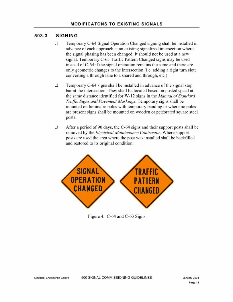
MODIFICATONS TO EXISTING SIGNALS
Electrical Engineering Centre 500 SIGNAL COMMISSIONING GUIDELINES January 2004
Page 15
503.3 SIGNING .1 Temporary C-64 Signal Operation Changed signing shall be installed in
advance of each approach at an existing signalized intersection where the signal phasing has been changed. It should not be used at a new signal. Temporary C-63 Traffic Pattern Changed signs may be used instead of C-64 if the signal operation remains the same and there are only geometric changes to the intersection (i.e. adding a right turn slot; converting a through lane to a shared and through, etc.)
.2 Temporary C-64 signs shall be installed in advance of the signal stop bar at the intersection. They shall be located based on posted speed at the same distance identified for W-12 signs in the Manual of Standard Traffic Signs and Pavement Markings. Temporary signs shall be mounted on luminaire poles with temporary banding or where no poles are present signs shall be mounted on wooden or perforated square steel posts.
.3 After a period of 90 days, the C-64 signs and their support posts shall be removed by the Electrical Maintenance Contractor. Where support posts are used the area where the post was installed shall be backfilled and restored to its original condition.
Figure 4. C-64 and C-63 Signs

Electrical Engineering Centre 500 SIGNAL COMMISSIONING GUIDELINES December, 2003
Page 16
504 CONTROLLER REPLACEMENT
504.1 GENERAL .1 This section details the process and traffic signing required for
commissioning a controller replacement at an existing signal. Typically this scenario shall apply where a controller has to be replaced as a result of a motor vehicle accident (MVA) or a replacement is made as part of general rehabilitation work activities.
504.2 PROCESS .1 The process for signal commissioning when the scope of the change is a
controller replacement shall cover all steps described below from the start to finish. The process steps are shown Figure 5. Controller Replacement Commissioning Flow Chart and described in the narrative below. The main elements of the process shall be as follows:
.1 Pre-Construction - The Manager Electrical Services shall arrange for the supply of the controller unit from the Electrical Engineering Centre based on this schedule. The Electrical Engineering Centrewill supply the required cabinet and controller to the ElectricalMaintenance Contractor who in turn will undertake the required shop testing listed below.
.2 Controller Shop Testing – Upon receipt of the controller from the Electrical Engineering Centre the Electrical Maintenance Contractor shall undertake shop testing in accordance with the current version of Ministry Section 400 Traffic Controller Cabinet Assembly and Testing document.
.3 Pre-Start Up – When shop testing is complete, the ElectricalMaintenance Contractor shall contact the Manager Electrical Services and arrange for the installation of the controller.
.4 Startup – The Electrical Maintenance Contractor shall complete the “Signal Start-up Check Sheet” and shall put the new controller directly into operation.

CONTROLLER REPLACEMENT
Electrical Engineering Centre 500 SIGNAL COMMISSIONING GUIDELINES January 2004
Page 17
Figure 5. Controller Replacement Commissioning Flow Chart

Electrical Engineering Centre 500 APPENDICES JANUARY 2004
Traffic Controller Design Manual
APPENDIX 500A PRE-START UP INSPECTION

Signal Pre-Start Up Inspection Sheet
Electrical Engineering Center 500 SIGNAL COMMISSIONING MANUAL November 2003 Page 1 of 3
Location _______________________________________________________________
Project No. ____________________ Drawing No. ________________________
Company _______________________________ Date___________ Time _________
Electrician ______________________________
Checked Inspection Item Pass Fail Initials
Luminaire, Signal and Sign Poles
.1 Check signal pole shafts are plumb and for proper arm rises (2 to 5 degrees from horizontal)
.2 Check for double nuts as per SP635 drawings
.3 Check any scratches in the galvanized surfaces are repaired with cold galvanizing compound
.4 Check nut covers are installed
.5 Check hand hole covers are installed
Traffic Signal and Pedestrian Heads
.1 Check all signal and pedestrian heads are properly oriented as per SP635 drawings.
.2 Check all signal and pedestrian heads and mounting hardware are securely attached to the pole using approved mounting hardware.
.3 Check all signal and pedestrian heads are bonded.
.4 Check signal heads are sacked (new signals)
Pedestrian Pushbuttons
.1 Check pedestrian pushbuttons and signs are securely attached to the pole.
.2 Check pushbuttons and signs are installed at the correct elevation and display the correct messaging.
.3 Check pushbutton signs are sacked

Signal Pre-Start Up Inspection Sheet
Electrical Engineering Center 500 SIGNAL COMMISSIONING MANUAL November 2003 Page 2 of 3
Luminaires and Photocells
.1 Check flat glass lenses are level
.2 Check luminaires are securely attached to the poles
.3 Check all photocells are aimed north
.4 Check all luminaires are operational
Signs and Pavement Markings
.1 Check signing and pavement markings are installed as per the design drawings
.2 Check all signs are installed, level and securely attached
.3 Check signs are visible to oncoming motorist a minimum of 100m from the sign
Service Equipment
.1 Check all service panels and conduits are securely attached to the pole
.2 Check wiring inside the panel is neat, correctly terminated and conforms to the requirements of the wiring diagram on the plans
.3 Check that ground plate or rod is installed
.4 Check all service connections have been made and the panel is fully operational
.5 Check drain screws in the bottom of the panel are removed
Wiring
.1 Check all conductors are the proper sizes and correctly color coded as indicated on the plans
.2 Check all conductor splices are securely connected and sealed with tape or sealant
.3 Check all bond conductors are green
.4 Check all conductors are RW90 (XLPE)

Signal Pre-Start Up Inspection Sheet
Electrical Engineering Center 500 SIGNAL COMMISSIONING MANUAL November 2003 Page 3 of 3
stranded copper
.5 Check all lighting circuits are correctly fused (check fused line and load sides are correctly oriented)
.6 Check all conductors are neatly coiled and bundled in all junction boxes, vaults, poles hand holes, controller cabinet and service panels (conductors shall be attached to conduit support bars in junction boxes and vaults).
.7 Check conductors are properly tagged in all junction boxes, vaults and controllers
.8 Check all signal and pedestrian phases have been flashed out
Detector Loops
.1 Obtain loop check sheets from the Electrical Installation Contractor and review for compliance
.2 Check all loops are color coded and labeled in the junction boxes
.3 Check loop slots in asphalt are properly sealed

Electrical Engineering Centre 500 APPENDICES JANUARY 2004
Traffic Controller Design Manual
APPENDIX 500B START UP INSPECTION
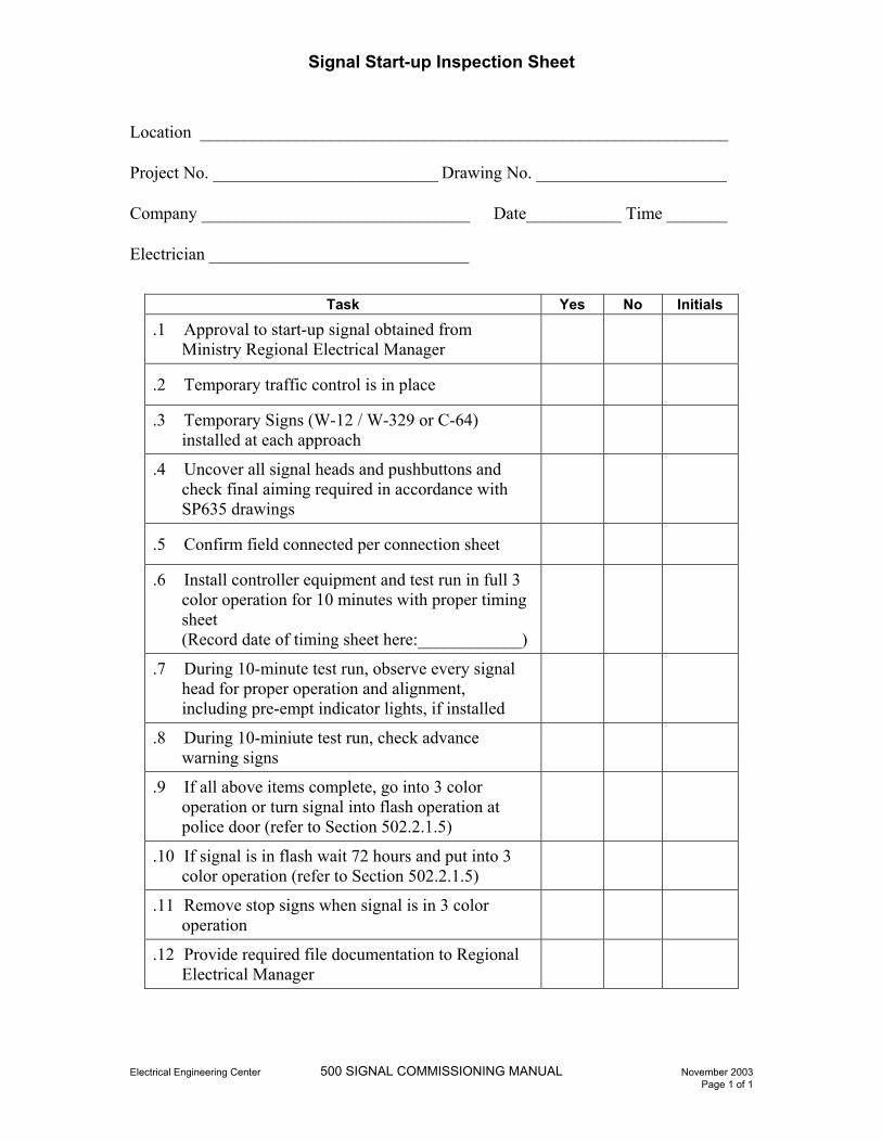
Signal Start-up Inspection Sheet
Electrical Engineering Center 500 SIGNAL COMMISSIONING MANUAL November 2003 Page 1 of 1
Location _____________________________________________________________
Project No. __________________________ Drawing No. ______________________
Company _______________________________ Date___________ Time _______
Electrician ______________________________
Task Yes No Initials
.1 Approval to start-up signal obtained from Ministry Regional Electrical Manager
.2 Temporary traffic control is in place
.3 Temporary Signs (W-12 / W-329 or C-64) installed at each approach
.4 Uncover all signal heads and pushbuttons and check final aiming required in accordance with SP635 drawings
.5 Confirm field connected per connection sheet
.6 Install controller equipment and test run in full 3 color operation for 10 minutes with proper timing sheet(Record date of timing sheet here:____________)
.7 During 10-minute test run, observe every signal head for proper operation and alignment, including pre-empt indicator lights, if installed
.8 During 10-miniute test run, check advance warning signs
.9 If all above items complete, go into 3 color operation or turn signal into flash operation at police door (refer to Section 502.2.1.5)
.10 If signal is in flash wait 72 hours and put into 3 color operation (refer to Section 502.2.1.5)
.11 Remove stop signs when signal is in 3 color operation
.12 Provide required file documentation to Regional Electrical Manager

SECTION 600 TRAFFIC OPERATIONS GUIDELINES
Electrical Engineering Centre
Version 4.0 January 2004

TRAFFIC OPERATIONS GUIDELINES
600 TRAFFIC OPERATIONS GUIDELINES
601 IMPLEMENTING SIGNAL TIMING PLANS.............................................. 2601.1 2 GENERAL ......................................................................................... 2
601.2 TIMING PLAN / CONTROLLER DESIGN INCONSISTENCIES .......... 2
602 TEMPORARY TIMING PLAN MODIFICATIONS...................................... 3603 CONTROLLER VOLUME LOGS AND MOES.......................................... 4

IMPLEMENTING SIGNAL TIMING PLANS
Engineering Branch 600 TRAFFIC OPERATIONS GUIDELINES January 2004
Traffic Controller Design Manual Page 2
601 IMPLEMENTING SIGNAL TIMING PLANS
601.1 GENERAL .1 The Ministry will create and distribute traffic signal timing plans. Timing
plans will be created and distributed for the following situations:
.1 New Traffic Controllers or Modifications to existing Controllers
.2 Observed Operational Field Problems
.3 Scheduled Roadway Maintenance
.4 New Coordination Plans
.2 Traffic controllers shall be programmed as per the timing plans issued, the Ministry LMD8000 Programming Manual, controller construction document and any other documentation that may be issued from time to time.
.3 A Traffic Signal Record Form shall be completed for the following:
.1 All timing plan changes.
.2 All new signal installations
.3 All modifications to existing signals
.4 All replacements due to Motor Vehicle Accidents
.4 A copy of the Traffic Signal Record form is included in the Appendix 600A.
601.2 TIMING PLAN / CONTROLLER DESIGN INCONSISTENCIES.1 The Ministry shall endeavor to provide accurate signed and sealed traffic
signal timing plans and controller design documentation for each new project.
.2 If documentation inconsistencies are encountered for new projects and the timing plans cannot be implemented as provided, the inconsistency shall be immediately documented in writing and forwarded to the Manager, Electrical Services for resolution; any implementation deadlines shall be extended for a period equal to the time it takes to resolve the discrepancy.
.3 The Ministry shall typically provide a complete set of documentation for each existing traffic signal. If discrepancies between the documentation and field conditions are detected, then:

TEMPORARY TIMING PLAN MODIFICATIONS
Engineering Branch 600 TRAFFIC OPERATIONS GUIDELINES January 2004
Traffic Controller Design Manual Page 3
.1 Electrical Design drawings shall be marked in red identifying any error(s). A copy of the drawings shall be sent to the Manager, Electrical Services for forwarding to the Electrical Engineering Centre for updating. The Ministry will decide when to update and release new electrical design drawings. Some drawings may not be electronically updated until further revisions are performed at a later date.
.2 Traffic Controller Drawings shall be marked in red identifying any error(s). A copy of the drawings shall be sent to the Manager, Electrical Services for forwarding to the Electrical Engineering Centre for updating. The Ministry will decide when to update and release new traffic controller drawings. Some drawings may not be electronically updated until further revisions are performed at a later date.
.3 Loop Assignment Sheets (Excel Spreadsheet) shall be corrected and a copy forwarded to the Manager. Electrical Services and Electrical Engineering Centre for their records.
.4 Traffic Signal Timing Plans shall be marked up in red identifying any discrepancies. A copy of the marked up timing plans shall be forwarded to the Manager, Electrical Services and Regional Traffic Engineer. The Ministry shall issue a revised timing plan addressing any discrepancies.
602 TEMPORARY TIMING PLAN MODIFICATIONS .1 The Ministry recognizes that certain field conditions are conducive to
modifying timing plans in a temporary and/or immediate manner. Typical situations would include failed loops causing traffic disruptions, or adjacent construction related work affecting intersection traffic flows.
.2 In order to allow flexibility in accommodating these types of events, the following timing parameters may be altered without the Regional Traffic Engineer issuing a new timing plan:
.1 Maximum Green times from a range of 50% to 200% of permanent values
.2 Recall from Off / Extendible to Maximum or Pedestrian Recall
.3 Minimum Green increased up to Maximum Green time (not to be used for signals that do not have alternate Minimum Green Entrytimings programmed during preemption phasing)
CONTROLLER VOLUME LOGS AND MOES
Engineering Branch 600 TRAFFIC OPERATIONS GUIDELINES January 2004
Traffic Controller Design Manual Page 4
.3 The traffic signal may also be removed from coordination for situations where the benefits of coordination have been reduced due to adjacent construction activities or failed detection.
.4 All temporary timing plan installations and removals shall be thoroughly documented and copies forwarded to the Manager, Electrical Services and the Regional Traffic Engineer for their information (Temporary Timing Plan Modifications do not require traffic controller programming data records to be printed). The temporary timing plans shall be monitored and any remediation work expedited to remove the temporary timing plan as soon as possible.
603 CONTROLLER VOLUME LOGS AND MOES .1 Some Ministry traffic controller cabinets are capable of providing volume
logs and measures of effectiveness (MOE’s). The logs shall be downloaded to a laptop computer at the controller cabinet; video detection volume logs shall be downloaded from the video equipment and loop detector counts shall be downloaded from the controller unit using LMSystem software. Logs shall be submitted to the Manager, Electrical Services via email.
.2 The volume collection capabilities of the controllers must be fully functional in order to collect the necessary data. If submitted volume logs indicate loop malfunctions, the field problem must be corrected and new volume or MOE information must be resubmitted (i.e. volume log and MOE submissions are considered complete only when accurate data is submitted).
Electrical Engineering Centre 600 APPENDICES JANUARY 2004
Traffic Controller Design Manual
APPENDIX 600A TRAFFIC SIGNAL RECORD
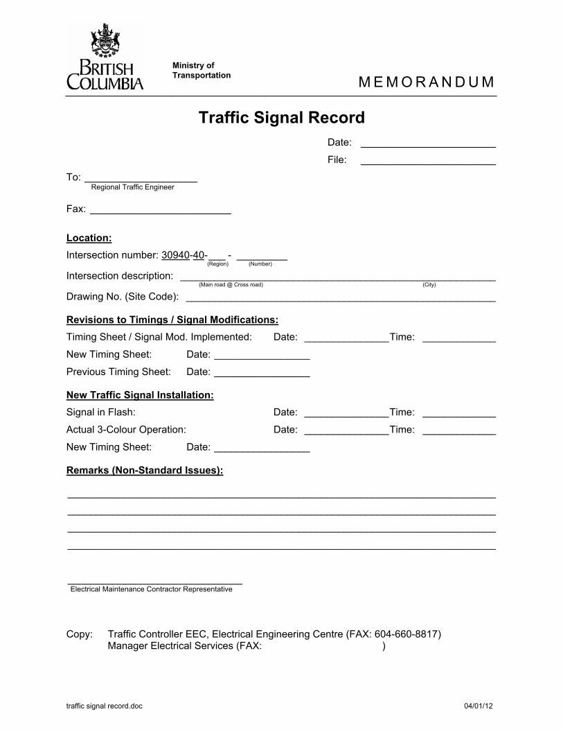
Ministry of Transportation M E M O R A N D U M
traffic signal record.doc 04/01/12
Traffic Signal Record Date: ________________________
File: ________________________
To: ____________________ Regional Traffic Engineer
Fax: _________________________
Location:Intersection number: 30940-40-___ - _________ (Region) (Number)
Intersection description: ________________________________________________________ (Main road @ Cross road) (City)
Drawing No. (Site Code): _______________________________________________________
Revisions to Timings / Signal Modifications:Timing Sheet / Signal Mod. Implemented: Date: _______________Time: _____________
New Timing Sheet: Date: _________________
Previous Timing Sheet: Date: _________________
New Traffic Signal Installation:Signal in Flash: Date: _______________Time: _____________
Actual 3-Colour Operation: Date: _______________Time: _____________
New Timing Sheet: Date: _________________
Remarks (Non-Standard Issues):
____________________________________________________________________________
____________________________________________________________________________
____________________________________________________________________________
____________________________________________________________________________
_______________________________ Electrical Maintenance Contractor Representative
Copy: Traffic Controller EEC, Electrical Engineering Centre (FAX: 604-660-8817) Manager Electrical Services (FAX: )