trailer remote control 446 122 080 0 - wabco...
TRANSCRIPT

TRAILER REMOTE CONTROL446 122 080 0
INSTALLATION AND CONNECTION INSTRUCTION


Trailer Remote Control
446 122 080 0
Installation and connection instructions
Edition 1
This publication is not subject to any update service. You will find the current version under http://www.wabco.info/8150101953
© 2012/2016 WABCO Europe BVBA – All rights reserved.
The right of amendment is reserved.Version 3/10.2012(en)
815 010 195 3

Trailer Remote Control
4
Purpose of publication
This publication applies to employees of a workshop for repairing utility vehicles with a knowledge of vehi-cle electronics. It details the installation and commis-sioning of the Trailer Remote Control (TRC) 446 122 080 0 in the towing vehicle.

Trailer Remote Control
Table of Contents
5
1 Symbols used 6
2 Safety information 7
3 Introduction 8
4 Function 9
5 Assembly 10
6 Connection to the power supply 11
7 Commissioning and functionality checks 16
8 Problem handling 17
9 Operating states 18
10 Annex 19 10.1 Vehicle list 19

1 Trailer Remote Control
Symbols used
6
1 Symbols used
CAUTION
Potential hazard situations that can cause minor or moderate personal injury if the safety instruction is not observed.
Important instructions, information, or tips that you should always observe.
Reference to information on the Internet
• List
– Step Consequence of an action

Trailer Remote Control
2Safety information
7
2 Safety information
Compliance of regulations / instructions
Read this publication thoroughly. Adhere to all instructions, information and safety information to prevent injury to persons and damage to property. WABCO will only guarantee the security, reliability and performance of their products and systems if all information in this publication is adhered to.
Make sure to follow the specifications and instructions of the vehicle manufacturer.
Maintain all accident regulations of the business as well as regional and national regulations.
Provisions for a safe work environment
Only trained and qualified technicians are to perform any work on the vehicle.
Use protective outfit if required (protective goggles, respiratory protection, ear de-fenders, etc.).
Pedal actuations can lead to severe injuries if persons are in the vicinity of the ve-hicle. Make sure that pedals cannot be actuated as follows:
• Switch the transmission to "neutral" and actuate the park brake.
• Secure the vehicle against rolling with chocks.
• Fasten a visible note to the steering wheel indicating the work is being per-formed on the vehicle and that the pedals are not to be actuated.
Do not wear a tie, loose clothing, open hair, arm bands, etc. when working on the vehicle, especially with the engine running. Keep your hands and hair away from the moving parts.
Your workspace must be dry as well as sufficiently illuminated and ventilated.
Keep flammable material (cloths, paper, etc.) away from the exhaust system.
Do not smoke in the workplace.
Use only devices that have proper electrical equipment.

3 Trailer Remote Control
Introduction
8
3 Introduction
These instructions describe the connection and commissioning of the Trailer Re-mote Control (TRC) 446 122 080 0 in the towing vehicle.
Trailer Remote Control makes it possible for the driver to control trailer functions from the driver's cab.
Trailer Remote Control is functional on a connected trailer with installed Trailer EBS E Premium Modulator as of version 2.0 and the electronic expansion module ELEX. The ignition must be switched on.
Trailer CAN-Router/Repeater requires communication on terminal 15 (Pin 2).
Recommended publications
More information on TEBS E, ELEX and Trailer Remote Control can be found in the following publications:
Technical documentation can be found on the Internet by entering the document
number in the online product catalogue INFORM http://inform.wabco-auto.com/intl/en/index.html (Link "Product number").
Publications Brochure Number XX = Language Code*
Trailer Remote Control - Operating Manual 815 990 193 3
TEBS E system description 815 XX0 093 3
*Language Code: 01 = English, 02 = German, 03 = French, 04 = Spanish, 05 = Italian, 06 = Dutch, 07 = Swedish, 08 = Russian, 09 = Polish, 10 = Croatian, 11 = Romanian, 12 = Hungarian, 14 = Turkish, 15 = Czech, 16 = Chinese, 17 = Korean, 18 = Japanese, 21 = Arabic, 24 = Danish, 28 = Finnish, 34 = Portuguese (Brazil), 98 = multilingual, 99 = nonverbal

Trailer Remote Control
4Function
9
4 Function
Trailer Remote Control is a display and control device for TEBS E functions and a distance display for TailGUARD functions in the trailer (more precise descriptions for the functions can be found in the TEBS E System Description).
Using a Trailer Remote Control is possible in any towing vehicle. The function only exists in combination with the electronic expansion module (ELEX) and a TEBS E2 Premium Modulator.
Trailer Remote Control enables the operation of trailer functions from the towing vehicle. The Trailer Remote Control communicates with the ELEX on the trailer via Power Line Communication (PLC). PLC is the generic term for the transfer of data via cables that are primarily used for the supply of power.
PLC enables the sending of information over long distances without the use of ex-tra cables and plug-in connections. A direction for the transmitted signals cannot be predetermined. This means that the signal is distributed to all connected com-ponents in a vehicle, i.e. to every part of the power circuit that can be used to re-ceive your communication. The signal is attenuated by other components in the circuit and it is sufficient for just a single component, because of its electrical char-acteristic, to affect the signal. As a result, the signal can not be evaluated and the communication is interrupted.
If the dampening caused by components in the towing vehicle is too great, a de-coupling between the Trailer Remote Control and the interrupting components can ensure sufficient signal quality in the direction of the trailer.
ELEX supports the communication via terminal 15 and terminal 30 of the 7-pin ISO 7638 trailer socket and automatically select the better of the two for communicating with Trailer Remote Control.
5 Trailer Remote Control
Assembly
10
5 Assembly
CAUTION
Traffic safety, functionality of the safety equipment – Install the Trailer Remote Control so that the driver's view is not obstructed and
access to all important controls is not hindered. – Make sure that the airbag functionality is not decreased in any way and that
there is no danger in triggering the airbag from the Trailer Remote Control while performing the installation.
– While installing, make sure that no important parts in the towing vehicle are damaged by the screws.
– Plan an install location for the Trailer Remote Control. – Check whether the fuse panel can be reached with the 4 m cable provided
when routed sensibly. Measure the distance from the planned installation loca-tion for the Trailer Remote Control (A-pillar or instrument panel) to the fuse panel.
– Install the Trailer Remote Control within the driver's view. A holder and four screws are provided with the delivery. As an alternative, other standard holders can also be used (e.g. suction cup mounts as used with standard navigation devices).
– Run the cable to the base of the windshield and then under the rubber seal to the fuse panel for example. More precise information on connection to the power supply see chapter 6 "Connection to the power supply", page 11.
Trailer Remote Control
6Connection to the power supply
11
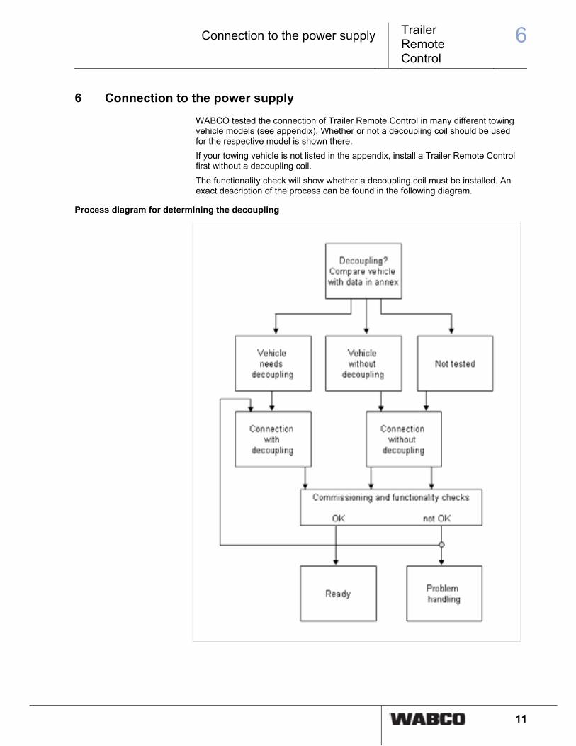
6 Connection to the power supply
WABCO tested the connection of Trailer Remote Control in many different towing vehicle models (see appendix). Whether or not a decoupling coil should be used for the respective model is shown there.
If your towing vehicle is not listed in the appendix, install a Trailer Remote Control first without a decoupling coil.
The functionality check will show whether a decoupling coil must be installed. An exact description of the process can be found in the following diagram.
Process diagram for determining the decoupling

6 Trailer Remote Control
Connection to the power supply
12
Procedure
Connection without decoupling
Connection with decoupling
Legend
1 ISO 7638 – Pin 1 Terminal 30 2 ISO 7638 – Pin 2 Terminal 15
3 ISO 7638 – Pin 3 Ground ECU 4 ISO 7638 – Pin 4 Ground Valve
5 ISO 7638 trailer socket 6 Trailer Remote Control
7 5 A fuse 8 Ground/Chassis
9 Supply lines terminal 15 and terminal 30 from other electronics that can weaken the PLC signal.
10 Decoupling coil
11 Power transfer point under the engine cowl 12 Battery of the towing vehicle
13 Fuse box in driver's cab 14 Ignition switch
1. Preparations
– Get the circuit diagrams for the towing vehicle. – Check for whether a decoupling coil has to be installed (see vehicle list in the
appendix).

Trailer Remote Control
6Connection to the power supply
13
2. Determine the line for terminal 30 of the ISO 7638 trailer socket
Pin Colour Assignments Cable
1 red Terminal 30 4 mm2
2 Black Terminal 15 1,5 mm2
3 yellow GND 15 1,5 mm2
4 brown GND 30 4 mm2
5 white Warning lamp 1,5 mm2
6 white/green CAN High 1 mm2
7 white/brown CAN Low 1 mm2
– Open the engine cowl and remove the cover for the power transfer point. – Look at the vehicle list in the appendix. The cabling for different models is simi-
lar with individual vehicle manufacturers, so that the respective cable of the ISO 7638 trailer socket often fit in the same socket. If your model is not listed but another model from the same manufacturer is listed, you can find the re-spective cable for you model using this model. The cable for terminal 30 (continuous positive) normally has a greater cross-section than standard cable, which can limit the search further.
– Connect a temporary test light between vehicle ground and pin 1 of the ISO 7638 trailer socket.
– Monitor the test light. – Disconnect the cable in question from the connector on the power transfer point
or pull out the fuse of the respective cable. If the light goes out, you have found the right line to connect to the Trailer Re-mote Control - possibly with attached decoupling coil.
Determine another suitable cable for connecting the Trailer Remote Control
The trailer must be equipped with ELEX and TEBS E as of version 2.0 and must be
connected to the towing vehicle via the 7-pin ISO 7638 trailer socket. The ignition must be switched on so that the Trailer Remote Control can receive a PLC signal of the ELEX."
– Connect the ground line (black) of the Trailer Remote Control cable to a good ground contact on the chassis.

6 Trailer Remote Control
Connection to the power supply
14
– Connect the power line of the Trailer Remote Control (red) with various cables at the power transfer point and observe the Trailer Remote Control: If the Trailer Remote Control performs an activation check (see chapter 9 "Op-erating states", page 18), power is being supplied. This is guaranteed with many cables; otherwise check the ground connection. If the Trailer Remote Control switches to operating mode after the activation check (illumination of all or individual pushbuttons), this line is suitable for a permanent connection. The signal quality can be improved in cases by inserting a decoupling coil.
3. Shut down the power circuit
CAUTION
Danger of injury by electricity, heat – To avoid shorts, pull out the fuse for the respective power circuit. – Disconnect the battery if necessary. However, the downstream theft-protection
systems may have to be reprogrammed. – Make sure the lines do not carry power before working on them.
4. Connection to the power transfer point
– Run the cable for the Trailer Remote Control through a suitable opening to the power transfer point.
– Connect the ground line (black) of the Trailer Remote Control with a good ground point on the vehicle (e.g. bolt on the steel frame, ground cable in the fuse panel).
If a decoupling coil has to be used, continue with chapter "7. Installing a Decoupling
Coil".
5. Connecting the Trailer Remote Control
– Protect the positive line of the Trailer Remote Control (red) with a 5A fuse. Use a free fuse block or an inline fuse holder.
– Connect the fused positive line with terminal 30 of the connecting line between the fuse panel and ISO 7638 trailer interface. As an alternative, the connection behind the fuse (in the fuse panel in the driv-er's cab) can be made at the line of the fuse on terminal 30 of the trailer, but not on all vehicles - depends on the electronics installed in the vehicle. After connecting the Trailer Remote Control to terminal 30, all LEDs of the Trailer Remote Control illuminate briefly and a short beep tone sounds (activa-tion check of the Trailer Remote Control with power supply) see chapter 9 "Op-erating states", page 18.
6. Final checks
– Make sure that all cables are connected properly and are insulated properly. – Check the Trailer Remote Control functionality see chapter 7 "Commissioning
and functionality checks", page 16. If the installation was successful, close up the power transfer point again. If the installation was not successful, check more points see chapter 8 "Problem handling", page 17.
7. Installing a Decoupling Coil
If no communication is possible with the ELEX in the coupled trailer, the attenua-tion of the PLC signal by the electronics installed in the towing vehicle is too great. The attenuation at the connection point of the ELEX or the Trailer Remote Control must be reduced with inductance.

Trailer Remote Control
6Connection to the power supply
15
An additional line (decoupling coil) serves for inductance and is inserted between the line for terminal 30 of the trailer socket and the power supply line of the towing vehicle.
– Find the line for terminal 30 of the trailer power supply (pin 1 of ISO 7638 sock-et).
– Disconnect this line from the supply of the towing vehicle by pulling the pin of the cable out of the plug-in connector or by cutting the cable.
– Make the decoupling coil. Make sure that the cross-section of the decoupling line is at least as great as the cross-section of the cable that the decoupling coil will be used in.
– Insert the decoupling coil between the plug-in connector and the line of the trail-er socket (length: 1,5 m - 4 m, cross-section: 2,5 mm²). Mark the decoupling coil with the following text "Do not remove - Decoupling coil required for the WABCO Trailer Remote Control", so that other workshops will not mistake the cable as an extra extension cable and remove it.
– Connect the Trailer Remote Control to the cable end that comes from the trailer socket because it will worsen communication otherwise.
– Continue with chapter "5. Connecting the Trailer Remote Control".

7 Trailer Remote Control
Commissioning and functionality checks
16
7 Commissioning and functionality checks
– Connect a trailer (with ELEX and TEBS E2 Premium Modulator) with to the tow-ing vehicle.
– Switch on the ignition. Activation check from Trailer Remote Control: All LEDs are illuminated for 1
second and a brief signal tone sounds (power is supplied). If there is communication with ELEX, the operating and display area is illu-minated (operating mode). Check for whether you can operate the defined functions for the trailer with Trailer Remote Control. Trailer Remote Control is connected correctly if operation is possible. Trailer Remote Control waits for an ELEX response for 1 minute. If the re-sponse is not received, the operating and display area is not illuminated and no operation is possible. Trailer Remote Control switches to sleep-mode. Perform more checks to rectify the problem see chapter 8 "Problem han-dling", page 17

Trailer Remote Control
8Problem handling
17
8 Problem handling
The following points must be completed so the ELEX and Trailer Remote Control can communicate:
• A trailer with ELEX and TEBS E2 (or higher) is connected to the towing vehicle with Trailer Remote Control via the trailer connector ISO 7638.
• The ignition in the towing vehicle is switched on (used for switching on ELEX).
• The communication to the Trailer Remote Control is activated in the TEBS E Diagnostics software (Page ELEX - Parameter => Communication to Trailer Remote Control active).
• The power supply of TEBS and ELEX is confirmed.
• The power supply of Trailer Remote Control is confirmed. Check for whether the activation check has been performed by Trailer Remote Control see chap-ter 9 "Operating states", page 18. If no activation check was performed, Trailer Remote Control is not supplied with power. Check the connection point and the ground connection of Trailer Remote Control for correct power.
• Check for whether a CAN router or CAN repeater is installed in the trailer. The PLC signal is weakened greatly by the CAN router or CAN repeater. Stable communication is normally no longer possible, but may be if Trailer Remote Control is connected directly to the trailer socket ISO 7638 of the towing vehicle and to terminal 15 (Pin 2 of ISO 7638) and not to terminal 30.
If these points are completed but there is still no communication between Trailer Remote Control and ELEX, another connecting point (another line in the fuse box or at the power transfer point) must be selected for Trailer Remote Control with less damping on the PLC signal or the connection must be made with a decoupling coil see chapter 6 "Connection to the power supply", page 11. If communication is still not possible, connect the line to the Trailer Remote Control directly to the ISO 7638 trailer socket (Pin 1 and 4).

9 Trailer Remote Control
Operating states
18
9 Operating states
The following is a description of the operating states of the Trailer Remote Control when connecting the towing vehicle.
Activation check
All Trailer Remote Control LEDs are illuminated for 1 second and a brief signal tone sounds.
Operating mode
The operating and display area of the Trailer Remote Control is illuminated. Trailer functions can be controlled via pushbuttons. If a TailGUARD function is activated (reverse gear engaged), the distance indicators are also illuminated (LED rows).
Waiting for communication
The middle yellow and the middle red LED rows flash briefly every 5 seconds for the duration of one minute.
Sleep mode
If no communication is established, Trailer Remote Control is inactive. In this case, all functions are switched off and the operating and display area of Trailer Remote Control is not illuminated.
Trailer Remote Control can be awoken from sleep-mode as follows:
• Press a button on the control.
• Remove the plug-in connector from the Trailer Remote Control and connected again.
After awaking from sleep-mode, Trailer Remote Control restarts and goes back into operating mode after the activation check.
Error mode
Active error (e.g. Error in TailGUARD system while the TailGUARD function is ac-tivated):
• Signal tone of 3 seconds
• Continuous illumination of the middle yellow and middle red LED rows.
Passive error (e.g. Error in TailGUARD system while the TailGUARD function is not activated)
• Illumination of the middle yellow and middle red LED rows once per second for the duration of one minute.
There is then no longer shown on the display (status the same as in operating mode).
Trailer Remote Control
10Annex
19
10 Annex
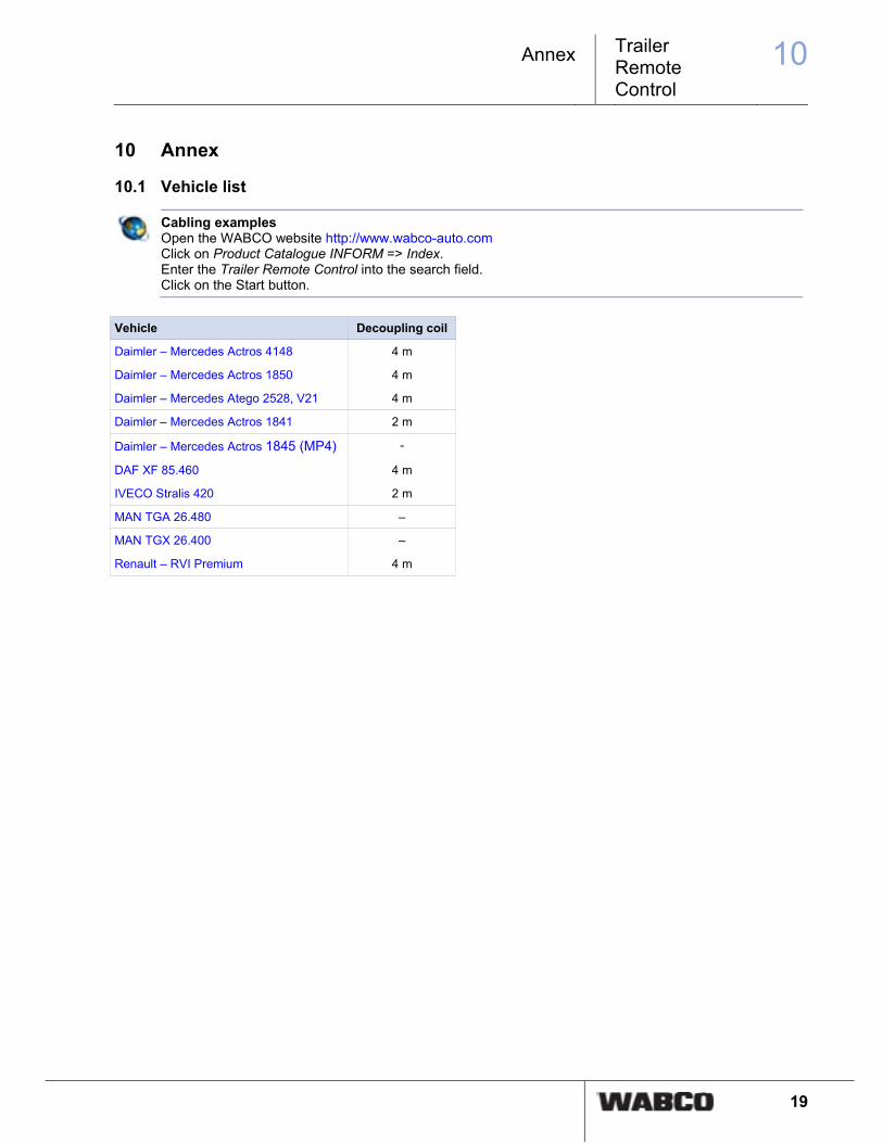
10.1 Vehicle list
Cabling examples
Open the WABCO website http://www.wabco-auto.com Click on Product Catalogue INFORM => Index. Enter the Trailer Remote Control into the search field. Click on the Start button.
Vehicle Decoupling coil
Daimler – Mercedes Actros 4148 4 m
Daimler – Mercedes Actros 1850 4 m
Daimler – Mercedes Atego 2528, V21 4 m
Daimler – Mercedes Actros 1841 2 m
Daimler – Mercedes Actros 1845 (MP4) -
DAF XF 85.460 4 m
IVECO Stralis 420 2 m
MAN TGA 26.480 –
MAN TGX 26.400 –
Renault – RVI Premium 4 m


© 2
012/
2016
WA
BC
O E
urop
e B
VB
A –
All
right
s re
serv
ed –
815
010
195
3 /
10.2
012manufacturers have WABCO
technologies onboard. In addition, WABCO provides the industry with advanced fleet management solutions and aftermarket services. WABCO reported sales of $2.9 billion in 2014. The company is headquartered in Brussels, Belgium, and has 11,000 employees worldwide. For more information, visit www.wabco-auto.com
WABCO (NYSE: WBC) is a leading innovator and global supplier of technologies that improve the safety and efficiency of commercial vehicles. Founded nearly 150 years ago, WABCO continues to pioneer breakthrough products and systems for braking, stability, suspension, transmission automation, and aerodynamics. Today, all of the world’s leading truck, bus and trailer