training adobe
TRANSCRIPT

PRODUCT TRAINING COURSE
Routine Maintenance & Service Instructions for Medium Voltage panels, vacuum circuit
breakers and contactors 3.3kV to 33kV.
For Hands-on, in-Situ Training...
© COPYRIGHT EXISTS IN THIS MATERIAL AND IT IS LENT WITHOUT CONSIDERATION OTHER THAN THE BORROWERS AGREEMENT THAT IT SHALL NOT BE REPRODUCED,
COPIED, LENT OR DUPLICATED, DIRECTLY OR INDIRECTLY, NOR USED FOR ANY PURPOSES OTHER THAN THAT FOR WHICH IT WAS SPECIFICALLY FURNISHED.
THE APPARATUS SHOWN ARE COVERED BY PATENTS.

9
Beginning of 1900’s
First research is done by Siemens in current interruption under oil & research into insulating mediums such as vacuum, solutions & gases
1960’s - Oil circuit breakers are in full manufacture, vacuum switching research & development successful, gas research & development continues First successful industrial manufacturing of the vacuum interrupter Further research into flow and electro-magnetic arc quenching in developing safer & more effective methods inside different mediums
1970’s Siemens develops concept of 3phase synchronised switching for vacuum interrupter technology, with application of a stored energy spring charge design derived from principles developed from already existing Siemens designs of operational pneumatic, compressed air type and spring loaded energy type switchgear mechanisms, as already operational with oil, air-blast, expansi’en & other switchgear, gas research is onto “SF6”
1977 First vacuum circuit-breaker manufactured by Siemens in Germany 1993 Siemens presents the world’s first low maintenance vacuum circuit-
breaker. 1998 Siemens combines the vacuum switching principle and disconnecting function mechanism for Earth switch in one module “NXACT”
2
THE ADVANTAGES OF SWITCHING UNDER VACUUM
Constant dielectric Hermetically sealed vacuum interrupter keeps out all environmental effects No gas decomposition products in vacuum
Constant contact resistance
In vacuum, contacts cannot oxidize The very small resistance is maintained throughout the contact life
High total current switched
Since contact erosion is small, rated normal current can be interrupted up to 30,000 times and rated short-circuit breaking current up to 100 times (and more)
Economic advantages
Vacuum interrupters are maintenance-free Modern vacuum circuit-breakers are also maintenance-free, e.g. Siemens type 3AH
3

Perf
CriRisk
Insp
Reli
Lifet
Ran
Swit
Dim
Cos
Perf
CriRisk
Insp
Reli
Lifet
Ran
Swit
Dim
Cos
ELECTROMAGNETIC ARC DIFFUSION IN A
Comparison of the arc quenching principles Vacuum and SF6
ormance of the mentioned quenching medium
Poor Good Very good Excellent
terion SF6 Vacuum of fire and explosion
ection of the quenching medium
ability in event of a leakage
ime
ge of breaking capacity
ching surges
ensions
t of maintenance
ormance of the mentioned quenching medium
Poor Good Very good Excellent
terion SF6 Vacuum of fire and explosion
ection of the quenching medium
ability in event of a leakage
ime
ge of breaking capacity
ching surges
ensions
t of maintenance
4

• Capacitors
• Arc furnaces
• Shunt reactors
The most important applications are the switching of:
• Transformers in distribution networks
• Cables and overhead-lines
• Motors
• Generators
Siemens Vacuum Circuit-Breakers can be used:- for all medium voltage applications
5

INTRODUCTION TO THE SWIT
WAThis equipment contains hazardous voltage
and may be c
Non- observance of the safety instructions canOnly qualified personnel should work on or
familiar with all warnings, safety notices, The successful and safe operation of this equi
operation a
INTRO The Siemens 8BF switchgear is a range of type rated voltages between 3.3 to 24KV. Within the 8B The 8BF00 type is a 600mm wide panel rated uinternal arc proof rating of 20KA to 31.5KA. The 8BF01 type panel is 800 mm wide and is rateinternal arc proof rating of 20KA or 40KA. The 8BF switchgear range is typically used foindustries.
CHBOARD & ITS COMPONENTS
RNING
s and mechanical parts which move at high speed ontrolled remotely.
result in severe personal injury or property damage. around this equipment after becoming thoroughly and maintenance procedures contained herein. pment is dependent on proper handling, installation, nd maintenance.
6
DUCTION
tested metal clad medium-voltage indoor switchgear for F Family there are two types of panels;
p to 12KV, 800A to 1250A and with a short circuit and
d up to 24KV, 800A to 3150A and with a short circuit and
r switching duties in mining, primary reticulation and

DESIGN FEATURES Metal partitions, subdivide each cubicle into; a bus bar compartment, a switching device, circuit breaker or vacuum contactor compartment, a MV cabling compartment, and a LV equipment and relay compartment. Circuit-breakers can be used in practically any system design.
7
Pressure release devices The compartments are each fitted with safety screens for deflection of ionized gases, and pressure relief flaps for explosive release of any ionized gases. All primary circuit compartments are fitted with pressure relief flaps for exhausting hot ionized gasses in the event of internal arcs, and are fitted with safety screens to direct the gasses upwards, providing total safety to personnel standing in close proximity of the switchgear during fault conditions. The internal compartment also has protective covers “flaps” where the contact arms of the circuit breaker enter the busbar and cable compartments. The purpose of these is to enable safe lock outs to both interconnecting compartments when the circuit breaker has been removed. Incomers and Tie-breakers are usually fitted with an additional spring operated explosion release flap. This flap usually remains open during normal operation, as it then acts as an additional cooling vent, allowing a passage for a convectional air flow. When an explosion occurs the vent is shut automatically by the escaping air flow and will remain closed. This will protect the operator and also cut off the immediate supply of oxygen into the compartment, thereby eliminating a possibility of a fire hazard.

BUSBAR DIFFERENCES BETWEEN 8 BF 00 AND 8 BF 01.
8

LV Control section MV Circuit breaker section
Cubicles are of a robust welded assembly with the LV compartment mounted above the circuit breaker compartment. Each compartment is independent and is separated by earthed sheet metal. The circuit breaker compartment houses the positively driven bus bar and cable shutters, which are pad-lockable. The padlock able cable earth switch is housed in the bottom of the cable compartment but operated from the circuit breaker compartment. The bus bar compartment houses the three main bus bars arranged in trefoil. The MV cabling compartment, housing the cable earth switch, current transformers and cable connections is accessed from the rear after removal of a bolted cover. The LV compartment houses control, metering, protection, switching and indication equipment.
Circuit breaker compartment, with cable and Bus bar cable shutters
9

10
Cable earth switch handle
Circuit breaker spring charge lever
Racking Handle
LV control panel door with control’s and LED indications, metering equipment, Test blocks, and other customer requirements Depending on the type of panel the following accessories are supplied: earth switch operating handle spring recharge handle racking handle
Control cubicle panel door
CCCiiirrrcccuuuiiittt BBBrreeeaaakkkeeerrr r SSSiiieeemmmeeennnsss 333AAAHHH vvvaaacccuuuuuummm ccciiirrrcccuuuiii ttt---bbbrrreeeaaakkkeeerrrsss {{{VVV---bbbrrreeeaaakkkeeerrr))) aaarrreee ooofff ttthhheee tttrrr iiipppllleee---pppooollleee iiinnndddooooorrr tttyyypppeee fffooorrr hhhiiiggghhh sswwwiiitttccchhhiiinnnggg fffrrreeeqqquuueeennncccyyy uuuppp tttooo aaa ssseeerrrvvviiiccceee lll iii fffeee ooofff aaattt llleeeaaasssttt 111222000,,,000000000 mmmeeeccchhhaaannniiicccaaalll ooopppeeerrraaattt iiinnnggg cccyyycccllleeesss... TTThhheee rrraaattteeeddd vvvooolll tttaaagggeee rrraaannngggeeess bbbeeetttwwweeeeeennn 333...333kkkVVV tttooo 333666 kkkVVV...
o
s
s
co e
g
CCCiiirrrcccuuuiii ttt---bbbrrreeeaaakkkeeerrrsss cccaaannn bbbeee uuussseeeddd iiinnn ppprrraaacccttt iiicccaaalll lllyyy aaannnyyy sssyyysssttteeemmm dddeeesssiiigggnnn
TTThhheee vvvaaacccuuuuuummm ccciiirrrcccuuuiii ttt---bbbrrreeeaaakkkeeerrr cccooonnnsssiiissstttsss ooofff ttthhheee mmmeeeccchhhaaannniiisssmmm hhhooouuusssiiinnnggg ccoommmpppllleeetttee wwwiiittthhh ssstttooorrreeeddd---eeennneeerrrgggyyy mmmeeeccchhhaaannniiisssmmm aaannnddd cccooonnntttrrrooolll eeellleeemmmeeennntttsss,,, ttthhheee ttthhhrrreeeeee pppooollleeesss wwwiiittthhh vvvaaacccuuuuuummm iiinnnttteeerrrrrruuupppttteeerrrsss,,, cccaaasssttt---rrreeesssiiinnn iiinnnsssuuulllaaatttooorrrsss aaannnddd ooopppeeerrraaattt iiinnngg rrrooodddsss... TTThhheee mmmooouuunnnttt iiinnnggg pppooosssiii ttt iiiooonnn {{{rrreeelllaaattt iiivvveee tttooo ttthhheee vvvaaacccuuuuuummm iiinnnttteeerrrrrruuupppttteeerrrsss))) iiisss vvveeerrrttt iiicccaaalll ...
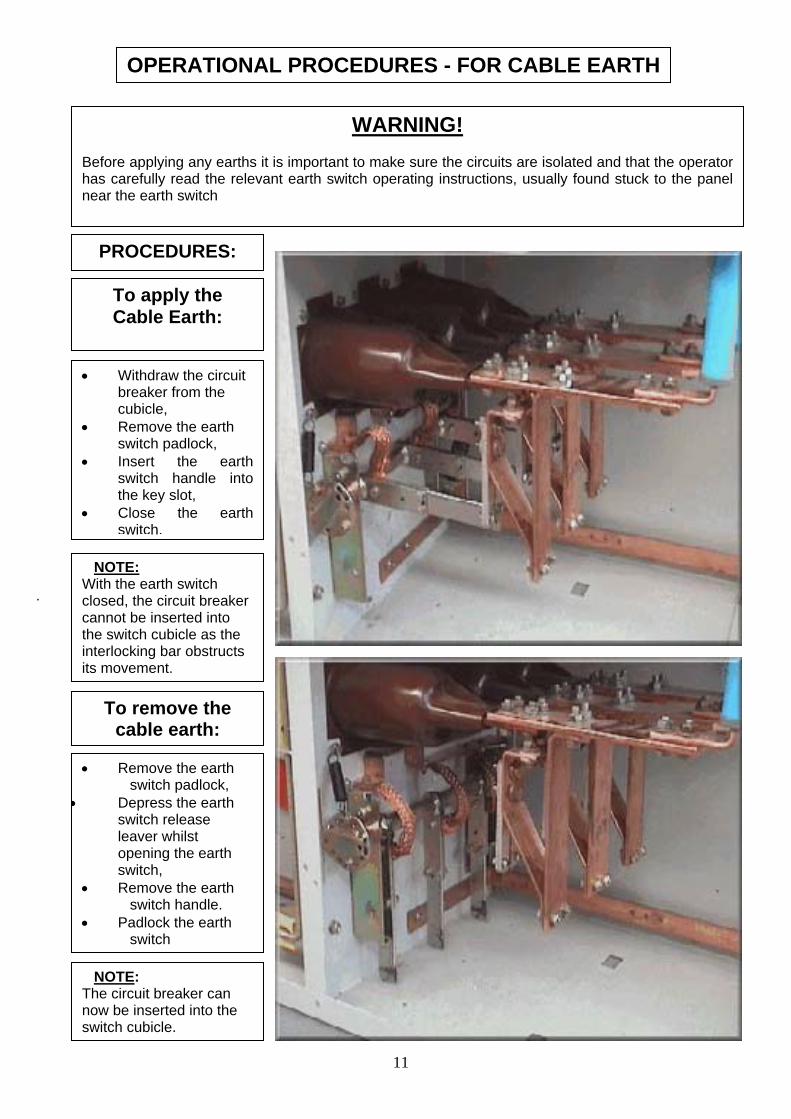
OPERATIONAL PROCEDURES - FOR CABLE EARTH
WARNING! Before applying any earths it is important to make sure the circuits are isolated and that the operator has carefully read the relevant earth switch operating instructions, usually found stuck to the panel near the earth switch
11
• Withdraw the circuit breaker from the cubicle,
• Remove the earth switch padlock,
• Insert the earth switch handle into the key slot,
• Close the earth switch,
PROCEDURES:
To apply the Cable Earth:
NOTE: With the earth switch closed, the circuit breaker cannot be inserted into the switch cubicle as the interlocking bar obstructs its movement.
.
To remove the cable earth:
• Remove the earth switch padlock,
• Depress the earth switch release leaver whilst opening the earth switch,
• Remove the earth switch handle.
• Padlock the earth switch
NOTE: The circuit breaker can now be inserted into the switch cubicle.

Cable and Bus bar earth trucks In our quest to improve the safety of our equipment we now offer Earthing circuit breaker trucks for bus bar and incomer Earthing applications. The bus bar earth truck is recognizable by its red front shield and contact arms only on the topside of the circuit breaker. The cable earth truck is recognizable by its yellow front shield and contact arms only on the bottom side of the circuit breaker. The operation of the bus bar and cable earth trucks would be dedicated to the specific boards, and the correct interlocking procedures for the specific board would have to be strictly followed.
Bus bar and cable Earth Trucks, identifiable by different coloured front shields
12

Cable Earth Truck
Note: Contact fingerslocated at the bottom
WARNING ! This equipment contains a stored energy type spring mechanism. The Kinetic force of the spring when charged is +/- 1Ton /per cm2 “DANGER”, as it can be released by accidental contact with the mechanism. Ensure that the Spring is discharged by inserting the handle into the front racking lever, turning it to the racked “in” position. Standing clear and away from moving parts, switch the mechanism “on” and “off” until there’s no further response from the mech. Take care when working on this apparatus, as all mechanical parts move at very high speeds & can cause severe property damage & disabling personal injuries. Only qualified personnel should work on or around this equipment after becoming thoroughly familiar with all warnings, safety notices, and maintenance procedures contained herein. The successful and safe operation of this equipment is dependent on proper handling, installation, operation and maintenance.
Bus bar Earth Truck
Note: Contact fingers located at the top
13


15

16
The Auto bonnet type VT fixture design The VT itself is firmly secured into the top panel VT box and this is secured to the panel by hinge like spring loaded counter-pressure arms. This type of design makes it possible to rack the VT out of circuit, and to lock it out in that position or for easy replacement in a case were this should ever be necessary. It is also beneficial for testing procedures such as Pressure testing the bus bar’s or cable’s within the panel. The connection points of the VT in the base of the VT box (which remains fixed to the top of the panel compartment) are all spring pin point loaded. These are placed under pressure against the contact points when the VT is closed. The advantage of this is that once closed there are no open wire or cable points exposed, as the VT can only operate in the closed and insulated position.
Bus bar and Cable mounted Voltage Transformers (VT’s) The following pictures indicate the panel cubicle mounted VT. This unit is mounted as shown on top of the incomer cubicle. It is connected with a special cable guided compartment, to either the top of the incomer points (bus bar VT) or to the live cable side bottom point of the incomer (Cable VT). In most cases the bus bar connected VT is a favourable norm, as in this type of arrangement it is possible to also isolate the VT output voltage by just switching the Incomer off. This is a design feature that is usually decided on by the client according to preference.

! ! ! - SAFETY PROCEDURES - ! ! !
WARNING
This equipment contains hazardous voltages and mechanical parts which move at high speed and may be controlled remotely.
Non- observance of the safety instructions can result in severe personal injury or property
damage. Only qualified personnel should work on or around this equipment after becoming thoroughly
familiar with all warnings, safety notices, and maintenance procedures contained herein. The successful and safe operation of this equipment is dependent on proper handling,
installation, operation and maintenance.
SAFETY FIRST ! The following Safety guidelines must be observed by the operator, or maintenance electrician, before performing routine maintenance and service on switchgear, to ensure that the procedure is performed correctly within the Safety regulations. The work is to be undertaken only by qualified electrical Artisans or technicians who are familiar with the operation and maintenance of the equipment in question, and are aware of all possible dangers involved with such procedures.
SAFETY PROCEDURES FOR FIXED MOUNTED CIRCUIT BREAKERS / CONTACTORS. Before commencement of any work the Artisan / Technician must ensure that the equipment concerned has been switched OFF and is ISOLATED on both sides and that the FEEDER to the SUPPLY side has been LOCKED OUT. PERSONAL PROTECTIVE EQUIPMENT MUST BE WORN DURING SWITCHING / TESTING / ISOLATION OR EARTHING OF EQUIPMENT!!! * (IN ACCORDANCE WITH LEGISLATION & ALL SAFETY REGULATIONS) * The equipment must then be proven ‘Safe’ with the use of a Phasing stick for (H.V.), and Voltmeter for (L.V.), by measuring each phase to the earth bar, or between phases to confirm that no voltage is present on both the Supply and Load sides. Special 1 into 3 Earthing leads, capable of carrying the maximum rated earth fault current, are to be used to additionally Isolate and earth the bus bars at both the Supply and Load ends. The Artisan / Technician is to ensure that the circuit breaker (if it is of the stored energy type) is not still charged and ready for operation, as the closing operation could accidentally be triggered whilst servicing the circuit breaker, with possible devastating effects. If the breaker is still charged, remove the electrical plug connector and mechanically push the On and Off buttons in sequence several times until there is no further response from the circuit breaker. Once the Artisans / Technician's are certain that the equipment is safe, the above requirements have been met, and a work permit has been issued, the service and maintenance procedures may commence.
17

SAFETY PROCEDURES FOR WITHDRAWABLE CIRCUIT BREAKERS / CONTACTORS. Before commencement of any work the Artisan / Technician must ensure that the equipment concerned has been switched OFF and is SAFE to be removed from the cradle or cubicle. PERSONAL PROTECTIVE EQUIPMENT MUST BE WORN DURING SWITCHING / TESTING / ISOLATION OR EARTHING OF EQUIPMENT!!! * (IN ACCORDANCE WITH LEGISLATION & ALL SAFETY REGULATIONS) * The Artisan / Technician is to ensure that the circuit breaker (if it is of the stored energy type) is not still charged and ready for operation, as the closing operation could accidentally be triggered whilst servicing the circuit breaker, with possible devastating effects. If the breaker is still charged, remove the electrical plug connector and mechanically push the “On” and “Off” buttons in sequence several times until there is no further response from the circuit breaker. Once the Artisans / Technician's are certain that the equipment is safe, the above requirements have been met, and a work permit has been issued, the service and maintenance procedures may commence.
TECHNICAL SPECIFICATIONS OF THE EQUIPMENT. Each circuit breaker and panel type is differentiated by its type number or lettering. These are important items that must be observed before any work commences on the apparatus. As this information will detail the particulars of the equipment that is to be serviced. There are many types of equipment and the specifications for these various types may differ considerably from one another. So care should be taken before attempting to service any equipment that we are familiar with what type of equipment we are dealing with, the dangers of such equipment and the methodology of the service requirement for such equipment.
Standard circuit breaker Name-plate representation
Basic type Rated voltage
Rated short circuit breaking current
Rated normal current
Note: In the event of any uncertainties or design code queries at a time of placing an urgent order for emergency spare parts; just state the type digit, the design code digit and the serial number of the equipment. This info will enable the operator of our 24hr Hotline to source any spares for immediate delivery locally, or within 24hrs abroad.
18

Standard specifications:
The 3AH1 vacuum circuit-breakers comply with the standards of IEC 56, IEC 694, BS 53111 and DIN VDE 0670. The V-breakers 3AH1 for 15 kV rated voltage meet the requirements of the American standards ANSI C37 with respect to their insulating capacity.
The following circuit breaker Types are utilised by Escom in the following Stations: Vygeboom – Types: 3AH1055-2; 3AH1054-4; 3AH5115-2 Bosloop – Types: 3AH1056-2; 3AH1056-4 Wintershoek – Types: 3AH1056-2; 3AH1056-4 Nooitgedacht - Types: 3AG1441-1 & 3AH Types as above
Ambient temperature, humidity and load-ability. The 3AH1-5 V-breakers are designed for the normal operating conditions laid down in the standards. Permissible ambient temperatures :Maximum value = +40 °C Average over a period of 24 hours = +35 °C Minimum value= – 5 °C Permissible atmospheric humidity, Relative humidity, 24 hour mean = max. 95% Relative humidity, 1 month mean = max. 90%. Under these conditions condensation may occasionally occur. The rated normal currents listed in the type designated tables as shown in the different catalogues, were laid down for 40 °C ambience in accordance with DIN VDE / IEC. Use, under conditions other than normal is possible with certain measures that can be implemented on request. The maximum permissible load current as a function of the 3AH - V- breaker ambient temperature have been plotted for your convenience, in each of the breaker’s companion manuals. The load currents indicated apply to open-type switch-gear. For metal-enclosed switchgear, these must be identified, as specified by their individual switchgear manufacturer’s Operating Manuals.
19

Site altitude
The insulating capacity of an insulation in air decreases with increasing altitude as a result of changes in the air density. Standards promulgated by DIN VDE, IEC and other disregard this decrease in insulating capacity for altitude of up to 1000 m, i.e. the decrease of approximately 9 % at this altitude is still permissible. The standards provide no guideline for altitudes of more than 1000 m with respect to insulation ratings; they leave this up to an agreement between manufacturer and user. Our own recommendation is as follows: Since this method used for rating insulation up to altitudes of 1000 m has proved to be satisfactory, it should also be applied to higher altitudes. The altitude correction factor should therefore be based on the insulating capacity at 1000 m, which is lower by 9 % (corresponding to 0.91) than the capacity at sea level. The following expression thus applies for selection of the equipment rated withstand voltage to be selected:
Reference: Circuit breaker operating manual
20

Description of Terms commonly used in circuit breaker technology Closing time = the interval of time between the initiation of the closing operation and the instant
when the contacts touch in all poles. Opening time = the interval of time between the initiation of the opening operation and the instant
when the contacts separate in all poles.
Arcing time = the interval of time between the instant of the first initiation of an arc and the instant of final arc extinction in all poles.
Break time = the interval of time between the beginning of the opening time of a circuit-breaker
and the end of the arcing time.
Close-open time = the interval of time ( in a make-break operating cycle) between the instant when the contacts touch in the first pole in the closing process, and the instant when the arcing contacts separate in all poles in the subsequent opening process. Switching duties = The operating mechanisms of the 3AH1 circuit-breakers are suitable for rapid
auto-reclosure. Breakers for a rated short-circuit breaking current of 40 kA are, at rated data levels, suitable for rapid load transfer; up to 31.5 kA they can also be used for rapid auto-reclosure.
Two Golden Rules before opening the circuit breaker / contactor front cover
21
C/B STATUS INDICATOR
ΙΙΙ - ON
Or
ΟΟΟ - OFF
= Closing Spring Discharged = Breaker is Condition – “OFF” (Safe to open front cover)
= Closing Spring Charged = Breaker in Condition – “ON” (NOT !!! Safe) - with either of the above conditions do NOT remove the front cover !

22
SERVICING GUIDELINES
Cleaning: Clean as required and at accessible intervals of +/- 6 months.
Re-greasing: Oiling and re-greasing of the mechanism need only be done after 10000 operations or every 5 years. This is, however, dependant on the status of the lubricants as derived from the annual inspection, as environmental factors could cause faster lubricant deterioration. Contact sys: Only to be checked every 10000 operations. Vacuum: Vacuum checks should be done annually during a routine service inspection. Interrupters: Vacuum Interrupters need only be replaced after 30000 operations or as required
Major Service is only required after 30 000 operations or approximately 10 years. This also depends on the type of breaker and the environmental factors, and performance of regular service inspections and cleaning. If no maintenance or inspections have been performed from time of installation, a major service is recommended, for Safety reasons, after 5 years. To mechanically operate a vacuum circuit breaker:
Conditions to be satisfied: • Ensure the racking handle is in the “racked in” position, • Ensure the interlock lever is in the interlock or locked position, • Charge the closing spring by inserting the hand crank into the spigot shaft and rotating clockwise until
the closing spring is charged, a loud click sound will be heard and the spring position indicator indicates charged,
• Depress the black close push button. The indicator will indicate “I” circuit breaker closed, • To trip, depress the red trip button. The indicator will indicate “O” circuit breaker open. To move a circuit breaker from the isolated or test position into the service or racked in position in an 8BF01 panel with positive racking the procedure is as follows:
• The circuit breaker must be open or in the tripped state, • Move the racking lever to the racked out position, • Insert the LV control plug and lock the retaining clip, • Insert the circuit breaker trolley into the panel until the front shield is approximately 15mm from the
final insertion point, • Move the racking lever form the racked out to the racked in position to fully engage the trolley into the
panel.
To withdraw or rack out the circuit breaker in a 8BF01 panel • The circuit breaker must be open or in the tripped state, • Move the racking lever to the racked out position, • Release the expulsion interlock by operating the foot pedal, • Withdraw the circuit breaker until the main contacts are isolated and the breaker is in the test position, • Disconnect the LV control plug and withdraw the circuit breaker completely from the panel.
To move the circuit breaker into the test position: • The circuit breaker must be open or in the tripped state, • Move the interlock lever to the free position, • Insert the circuit breaker trolley into the panel until the top shoot bolts line up with slots in the front
housing, • Insert the LV control plug and lock the retaining clip,

MAINTENANCE PROCEDURES FOR VACUUM SWITCHGEAR. The vacuum circuit breakers or contactors generally require little maintenance. The work to be done to ensure constant readiness for operation depends on the operating conditions and local circumstances. Under normal circumstances, however, a visual maintenance inspection on the state of the circuit breaker or contactor is recommended to be done annually.
1. ISOLATING THE VACUUM CIRCUIT BREAKER / CONTACTOR
The Artisan/Technician is to ensure that the circuit breaker or contactor is switched OFF, and ISOLATED. If the breaker is of the stored energy type, the circuit breaker mechanism must be discharged. For breakers with automated motorised charging, first remove the Plug connector. This will disconnect the supply from the auto recharging circuit and charging motor of the breaker operating mechanism. Then simply discharge the mechanism by switching the breaker “on” and then “off” again. As an additional precaution, attempt to switch the breaker “on” and “off” again. There should be no further response from the mechanism. It is now safe to work on the internal components once this condition has been achieved. Once the Artisan / Technician is certain that the equipment is safe, all the above safety requirements have been met, and a work permit has been issued, the service and maintenance procedures may commence.
2. ASESSMENT OF SERVICE INTERVALS FOR THE CIRCUIT BREAKER / CONTACTOR
The time and scope of work to be done is dependant on the following factors: 1. The operating time 2. The number of mechanical operating cycles 3. The number fault trip operations
The maintenance work below refers mainly to the breaker or contactor operating mechanisms. The vacuum interrupters are maintenance free until they reach the number of permissible operating cycles. It is, however, advised that certain interrupter criteria be checked and inspected as discussed later in the document.
23

3. SERVICING OF THE SWITCH-TRUCK AND SWITCHBOARD Prior to beginning with any maintenance and service work the responsible person must make sure that the equipment to be worked on is isolated and locked out according to recognized safety procedures. Isolate the control supply in the LV compartment. Rack out the circuit breaker or vacuum contactor and remove the LV control plug. Close the cable earth switch and padlock the earth switch, cable and bus bar shutters.
FIRST LINE MAINTENANCE AND SERVICE: THE CIRCUIT BREAKER / CONTACTOR TRUCK Before beginning to service a Siemens vacuum circuit breaker truck discharge the closing spring manually and remove all covers on the circuit breaker truck. Visually inspect the equipment for warn or damaged components; Counter Breaker indication Gearbox Closing coil Tripping spring Closing spring Closing button Tripping button S1 auxiliary contacts Spring charge motor Contact fingers Vacuum interrupters Tripping coil Re-lubricate the operating mechanisms with an approved Siemens lubricant. If a counter is fitted record the reading. This information gives an indication to the wear on the main interrupters. If the counter exceeds the maximum number of make or break operations for that particular breaker the nearest Siemens representative should be informed. To check the main contact wear, a marking is provided on the lower interrupter support. If the indicator is above the red mark when the circuit breaker is closed it indicates excessive contactor wear and the nearest Siemens representative should be informed. If it is suspected that a vacuum interrupter has lost its vacuum a high voltage test needs to be performed. Visually check that the carbon brushes of the spring charge motor are in good condition. Check the free movement of the closing and tripping coils. To check the latching of the operating mechanism the closing spring is charged manually and depressing the black close push button closes the breaker. The breaker should now be latched in the closed position. Depressing the red trip button to verify the mechanical tripping operation now trips the breaker. Wipe down and clean the circuit breaker truck. Replace all circuit breaker covers. Move the circuit breaker into the test position. To check the electrical close and trip operation of the circuit breaker, re-instate the control voltage and electrically operate the breaker. When complete, isolate the control voltage and rack out the circuit breaker.
Check the finger contacts for signs of over heating, contact tightness and contact alignment and lubricate with an approved Siemens lubricant. If the contact tightness or contact alignment needs adjustment the nearest Siemens Representative should be informed. Re-torque all the bolts on the circuit breaker arms according to the Siemens specifications.
FIRST LINE MAINTENANCE AND SERVICE: THE SWITCHBOARD Check free and smooth operation of the shutter mechanisms, clean and lightly lubricate the shutter operating rods. Visually inspect spouts for cracks, tracking and corrosion. Clean the circuit breaker compartment. Check correct operation of the earth switch making sure the cable is isolated before applying the earth switch. Check the correct racking in and out of the circuit breaker truck. Visually inspect the bus bar and cable compartments for dust contamination, deterioration of insulation and hot connections. Wipe down the insulators and clean the compartments. Visually inspect the cable earth switch for correct operation and contact penetration. Lubricate the operating mechanisms and contacts with an approved Siemens lubricant. Visually inspect that the explosion flaps are in a good order and report any defective flaps.
24

4. FIRST LINE MAINTENANCE FOR VACUUM CIRCUIT BREAKERS
4.1 INSPECTION OF THE VACUUM INTERRUPTERS Description of the Vacuum Interrupter Pole Assembly
Description Construction The vacuum circuit-breaker consists of the mechanism housing (60.) , the 3-pole assemblies (19.) with vacuum interrupters (30.), cast-resin post insulators (16.1 and 16.2), struts (28) and of the operating rods (48.) with contact pressure springs (49.). Each of the three pole assemblies (19.) is supported by two Cast-resin post insulators (16.1 and 16.2), which are bolted to the pole plate (15) respectively.
25

4.2 THE POLE ASSEMBLY The pole assembly (19.) consists of the upper interrupter support (20.) with the upper terminal (27.) , the vacuum interrupter (30.) , the lower interrupter support (40.) with the lower terminal (29.), the clamp (29.2.) with the flexible con- nector (29.1.) and the angled Lever (48.6.). The centring piece (28.1.) and the struts (28.) relieve the vacuum interrupters of external forces see (Fig. below).
TsDaciiTarI
4.3 The Vacuum Ihe basic construction of the vacuum interrupters for the ectional view in Fig. 2/5. .; epending on its type, the vacuum interrupter (30.) is fixrcing chamber (33.) is located between two ceramic insonnected directly with the housing. The moving contact pi
s located centrally in the guide (35.). The metal bellows (nterrupter housing. he vacuum interrupters fitted in the 3AH vacuum circuiccordance with the X-ray regulations of the Federal equirements of the X-ray regulations of January 8, 1987 (FII Section 5 up to rated short-time AC voltage stipulated in a
26
nterrupter 3AH4 vacuum circuit-breaker is shown in the
ed to the upper interrupter support (20.). The ulators (32.). The fixed contact piece (31.) is ece (36.) is fixed to the terminal bolt (36.1) and 34.) forms the vacuum-proof connection to the
t- breakers are type tested and -approved in Republic of Germany. They conform to the ederal Law Gazette Page 144) § 8 and Annex ccordance with DIN VDE/IEC.

4.4 Checking the contact System of the vacuum Interrupters The contact system is subject to wear by both contact erosion and by compression of the contact pieces and the guide bolts. Note: With some earlier 3AG types, the moving terminal bolt (36.1) of the vacuum interrupter (30.) is provided with the check marking (13.9). As long as the white dot marking is wholly or partially visible when the 3AG vacuum circuit-breaker is closed, the shortening of the contacts is within the permissible range. With the newer 3AH types, the indicator for checking the contact wear is located on the side of the lower Pole assembly of the moving contact rod housing. This is either indicated by a sticker marking showing a red line. This sticker is fixed to the poles and indicates the initial closed contact state position, after assembly and testing as the circuit breaker, before it was released from the factory
Legend 13. Check marking 30 Vacuum interrupter 36.1 Drive and terminal bolt
Checking the contact wear Each interrupter is pre-manufactured with a white punch mark, or a marking sticker, which can be found in the keyway of the moving contact shaft, or the side of the lower contact pole housing. With the interrupter in the closed position, this white dot must still be visible. With intensive switching this dot will slowly move into the interrupter, as the contacts become worn. In the case where this is indicated by a red line sticker, the original position marking will move away from the closed position line. Once this dot / line moves further and further into the interrupter, or apart, the interrupter should be replaced just before the dot disappears completely, or the line spacing becomes excessive. An alternative, and by far more accurate method of determining the contact wear, is to individually measure each interrupters difference between the open and closed positions. Once this result has been measured, it must be compared to the original setting differential as given in the specification for the Interrupter and breaker type. In this way, as an example, the original setting may be (10 + 1) this indicating that the original setting was between 10 and 11 mm. Compared to the measured value, now of say 12.8mm. This indicates that the contact wear would be approximately 1.8 mm, which is within tolerance of the specified 3mm permitted. From this one could determine the remaining life expectancy of the interrupters, as say the breaker or contactor has been in operation for 5 years, it has worn 1.8mm. Therefore the next inspection should be planed for (1.8 divided by 5) multiplied by (the amount of further unknown service years) for the answer to be less than 1.2mm (the available contact remaining). As an equation: (1.8 / 5) x y = 1.2 (where y = the remaining life expectancy).
4.5 Checking the vacuum The first method is used primarily on the 3AG types. This method requires the contact pressure springs to be disengaged, as well as the moving contact arm rod from the base of the interrupter. The vacuum is then checked by forcing the contact lever mechanism open. There should be a firm resistance when trying to pry open the contacts, if so, the vacuum within the bottle is still present. We recommend however, that a safer method with types 3AH be used, which is to pressure test each individual pole with the breaker in the open position. Such a check should be made if there is any risk of an interrupter having developed a leak. Bus bar and cable connections must be split. The check is performed with an HV test unit. If necessary, further information may be obtained from the appropriate Siemens Regional Office.
27

4.6 REPLACING THE VACUUM INTERRUPTERS
___________________________________________________ PLEASE NOTE : - FOR INFORMATION ONLY -
NB. - This task is only to be performed by qualified or specifically trained personnel, as the incorrect fitment of new vacuum interrupters onto a circuit breaker can have devastating consequences to all staff, equipment, machinery and production. There are various cautions and tests performed with this procedure, which are not listed herein.
The topics as discussed in this manual are for your information only, as they are only a brief and basic description of the core tasks performed when replacing vacuum interrupters at the works. This is included as an informative part of the training only. Siemens can therefore not be held liable or responsible for any loss of life, damages, or losses of what ever nature - what so ever - should this occur as a direct result of an attempt to change interrupters using the information as contained herein.
(For assistance with this procedure, please contact your nearest Siemens office. Or call 012 309 0128)
Example for vacuum circuit-breaker models with Vacuum Interrupters type “VS”
Removing an Interrupter
1. Isolate the circuit breaker . 2. Slacken the lateral bolt or bolts on terminal clamp 29.2. 3. Withdraw pin 48.5 from insulated coupler 48. and levers 48.6. 4. Remove the coupling pin from adapter 36.3. 5. Unscrew struts 28. from the upper pole support 20., slacken them on the lower pole support 40. and swing them
forward. 6. Undo centring ring 28.1. 7. Undo fixing screw B of the interrupter at the upper pole support 20. Push interrupter 30., together with adapter
36.3 down by about 6 mm, take out the ball cup “A” from between the interrupter and the upper pole support. Tilt the interrupter forward and withdraw it from the lower pole support 40.
Installing an Interrupter Note: Replacement interrupters 30. with screwed-in adapters 36.3 have been adjusted at the works. Do not alter the adapter setting.
1. Rub and lubricate the connection surfaces. Copper sprayed connection surfaces of aluminium parts and silver plated surfaces of copper parts may only be cleaned with a rag.
2. Insert interrupter 30. (with its evacuation nipple facing the mechanism housing) in the lower pole support 40. Slip terminal clamp 29.2 into position.
3. Place ball cup A on the upper contact surface 31.1 of the interrupter. Screw this finger-tight to upper pole support 20. using screw B, the spring washer, the ball cup and washer, and the flat washer .
4. Firmly bolt struts 28. to pole support 20. Also tighten the bolts on the lower pole support 40.
5. Couple levers 48.6 and drive links 48.9 to adapter 36.3 using the pin supplied and lock this.
6. Push terminal clamp 29.2 and if applicable spacer tube 29.3 (only required for flat terminal clamp: see detail X on drawing) against the looking ring or step on the movable terminal bolt 36.1 and position interrupter 30.,so that its groove faces the connection surface of flexible strap 29.1. Tighten the bolt or bolts of terminal clamp 29.2 with a torque of 20 Nm respectively 40 Nm, taking care to see that the copper terminal of the interrupter is not subjected to an undue bending moment. This is achieved by tightening the bolt in the manner shown, using a torque wrench. Use a corresponding wrench to hold the nut.
7. Tighten the interrupter fixing screw B on the upper pole support 20. , holding the interrupter firmly by its upper Insulator and operate lever 48.6 by hand to see whether the moving contact moves freely. If need be, undo screw B and adjust the interrupter in pole support 20. by turning and moving it slightly.
8. Tighten centring ring 28.1
28

29
(Stroke excessive -Turn out eyebolt Stroke too short -Turn in eyebolt)
6. Repeat the measurement in accordance with 3 and 4.
3AF 93. .: (20 -1)
5. The stroke can be adjusted to suit by altering the setting of the eyebolt in insulated coupler 48.
3AF 35.. : (25 -1) ; 3AF 35...from year of manufacture 1990: (20 -1) ; 3AF 37../67.. : (20 -1); 3AF 92.. : 16 -1
3. Measure the distance between the lower edge of the lateral cut-out in pole support 40. and the lower edge of terminal clamp 29.27 using vernier callipers.
4. Again link insulated coupler 48. and levers 48.6 together and repeat the above measurement. 5. The difference of both measurements is the stroke.
Examples of Set-points:
9. Link insulated coupler 48. and lever 48.6 together by means of pin 48.5 and lock the pin in position . 10. Open and close the breaker several times off-load and then check to see that all the screwed joints are tight.
Checking the contact stroke
1. Trip the Breaker.
2. Remove pin 48.5. The interrupter contacts must now close automatically.

30

DETAILS OF VACUUM CICUIT BREAKER ATTRIBUTES
31

4.7 INSPECTION AND SERVICE OF THE OPERATING MECHANISM
GENERAL DESCRIPTION OF THE OPERATING MECHANISM The mechanism housing (60.) accommodates all electrical and mechanical elements required for opening and closing the vacuum circuit-breaker. The diagrams which follow show the arrangement of the individual modules in the mechanism housing. The mechanism housing has a detachable cover 60.1 This cover (60.1) has cut-outs for the actuating and indicating devices. The vacuum circuit-breaker is closed by means of the push-button (53.). The cover includes an opening (50.1) for the hand crank. The stored-energy mechanism state is shown by the indicator (55.1). The indicator (59.1) shows the breaker state (ON -OFF). The operating cycle counter (58.1) indicates the number of “ON-OFF” charging operations. The rating plate (51.) is attached to the mechanism hosing but visible trough an opening (51.1) on the cover. The different types of circuit breakers i.e. 3AG or 3AH differ slightly in front cover layout and appearance, but this is due to small differences in operating mechanism design. Yet, all the basic elements shown here on the operating mechanism front cover are the same for most 3AF or 3AH types, but their positions may vary.
32
The motor (50.4) immediately recharges the closing spring (62.) .In the event of motor power supply failure, the closing spring can be charged by means of a hand crank (50.).The movement is transmitted to the pole assemblies via moulded-plastic operating rods (48.). ) for the hand crank, behind which the hand crank coupling (50.5) of the gearing (50.2) is located. The stored-energy mechanism state is shown by the indicator (55.).

4.8 MECHANICAL SERVICE & INSPECTION Remove the front cover of the breaker to expose the operating mechanism. Check each mechanical part within the mechanism for wear or possible damage. All friction surfaces must be adequately lubricated. Also check the status of the lubricant, by rubbing it onto 2 fingertips and moving then back and forth against one another. The grease must feel soft and smooth and must not pull into threads when fingers are pulled apart. If the lubricant is dry, or sticky, it must be removed from the mechanism before application of the new grease. This may be done with the use of electrical cleaning solution and a cloth, but not on parts within direct contact of plastic. These must be cleaned with a soap solution, and then treated with lubrication spray before application of new grease. The type of grease to be used as a replacement in the operating mechanism as per specification is Kluber Isoflex Topas L 32. Check if the breaker mechanical truck interlock is operational, the breaker must not be able to close when the racking lever is in the racked out position. Also check, that when the lever is turned to the racked in position the limit switch at the base of the lever extension makes adequately. The damper rubber for trip shock absorbency, at the base of the shaft, must be checked that it is loose and free to move. On the contact arms, check that the contact finger spring tension and the condition of the spring support assembly, this may be done with a Jig, the same thickness as that of the receiving contact copper bars. Tension on the Jig piece must be tight, and all parts of the assembly must be clean. (Treat for Rust protection). On completion lubricate the contact arm fingers with Klubber long term 2 plus.
Lubrication points of the operating mechanism
Key to Parts a Crank pin for push
-button operation b Lever bearing c Cam contour d ON latching e Diverting auxiliary
switch f Auxiliary switch g Opening spring
guide h Diverting auxiliary
switch j Switch shaft bearing k OFF latching I Cam OFF latching m Stop p Opening spring
bearing
=
=
Key of Lubricant types
Lubricant order Information
33

4.9 ELECTRICAL SERVICE AND INSPECTION Check each electrical connection on the terminal rail and within the operating mechanism for tightness and good contact. Check the existing wires for any visible insulation damage, and that they are clear from moving mechanical parts and firmly strapped. Check all electrical components such as limit switches, mechanical operated relays and contactors. These must be functional and easy to operate. Should any of these be tight or damaged, then treat with electrical contact spray or replace as required. If the breaker is fitted with a connector plug, the connector pins on both ends of the plug must be inspected. Check for any loose connections, plug pins and burnt pin tips. Replace or amend as required.
.
SERVICE COMPLETION & PUTTING BACK INTO OPERATION On completion of the service inspection, ensure that all parts and components of the circuit breaker have been correctly re-assembled and that all service tools and accessories are removed. Ideally, a few mechanical test operations (+/- 5) should be performed to ensure correct function. This will also allow newly applied grease and lubrication to penetrate all treated components.
With removable breakers, the test operations may be done with the breaker racked into the test position, where after, if successfully tested, the breaker may be put back into normal operation.
With fixed mounted breakers however, the test operations have to be done with the breaker in position. It is important, in this case, to take special precautions when testing the breaker.
The bus bar connections are still earthed, and the supply side isolated. As a special precaution, remove the earth connections from the breaker, but leave the supply side Isolated and locked out. The breaker may be switched on and off mechanically in this condition where after, if successfully tested, the breaker may be put back into normal operation.
In performing the test operations it is possible in both the above cases, that the breaker will trip immediately if the mechanism is fitted with an under-voltage coil, or if the internal shunt-trip is being triggered from the auxiliary protection circuit. In this case, an auxiliary supply will be required to hold in the under-voltage coil (at the correct voltage as indicated on the coil), and / or the supply wire to the shunt trip coil may be temporarily removed for test purposes.
Note: for fixed mounted breakers this must only be done if the supply side is isolated and locked out, for removable breakers this must only be done if the breaker is in the test position. In both cases, there must be no live switching of power during the test operations.
34

5. FIRST LINE MAINTENANCE FOR VACUUM CONTACTORS
5.1 INTRODUCTION Note: The procedures for maintaining contactors follows very closely to that of circuit breakers. Contactors however, do not require as thorough a service inspection as with circuit breakers. Contactors carry an interrupter-life time guarantee and are designed in such a manner that they allow for wear and tear, without affecting adjustment. It is recommended to do a minimum of at least 1 visual inspection per annum, just to ensure that all is still within the safe operating parameters. Some contactors may differ with regard to their lifetime and guarantee, with the amount of operations being subject to change pending the type of contactor ordered. This lifetime is distinguished by the model classification with reference to the product catalogue. The main difference between a vacuum contactor and a vacuum circuit breaker is that the contactor utilises the electromagnetic coil effect for its operation, sometimes supported by a spring-loaded trip mechanism which is charged during the electric closing operation, in order to speed up breaking-operation time. The vacuum circuit breaker on the other hand is opened and closed purely via mechanical loaded spring force, where in most cases an electric motor is used to charge the closing coil-spring which retains and stores its energy, until triggered by hand or solenoid. The trip spring is charged during the very powerful closing spring operation. The spring in a high speed mechanism can induce a force of approximately 1Ton / per cm. (fingers passop!!!!)
Construction The HV vacuum contactor comprises three subassemblies: 1. - The HV section with the three vacuum interrupters 2. - The LV section with the solenoid-operated mechanism, the central terminal block, the contactor relay, the economy resistor, the auxiliary contacts and 3. - the drive lever.
High-voltage vacuum contactors are switching devices with solenoid-operated mechanisms suitable for high switching frequencies and unlimited ON duration. The solenoid-operated mechanism is suitable for AC or DC duty. The vacuum contactors are suitable for normal switching operations in AC circuits of any type, e.g. three-phase motors, transformers, capacitors and resistive loads. They are suitable for motor reversal duty (refer to diagram in catalog HG11 section 4). The vacuum contactors are of the non-enclosed type, degree of protection IP 00 to DIN 40 050 and IEC 144. They are suitable for use in buildings with poor thermal insulation or low thermal capacity, heated or cooled, without temperature monitoring; heating or cooling may even fail for several days. Condensation about once a month for 2 hours is permissible.
35

Vacuum contactor with cable harness connected up
Contactors - & The effects of Operational Altitude Adjusting the vacuum contactor according to the site altitude Adaptation work must be done before the drive is installed! Adjustments on the rear of the vacuum contactor are necessary if the site altitude is different from that set at the works, (-200 m to +1250 m). Press in both setting plugs using a screwdriver until the setting plug can be turned. Then turn the setting plug to the setting mark of the corresponding site equipment-situ altitude
36

Triple-pole vacuum contactor 3TL61
1 Moulded-plastic h2 Drive c
ousing hamber
rrupter 3 Drive lever 4 Vacuum inte5 Upper terminal 6 Lower terminal 7 Side plate
37

Mode of operation The drive lever (3) takes the form of angle lever with point A as the fulcrum. This lebetween the solenoid-operated mechanism and the vacuum interrupter. When the mthe "Off" position by the compression springs (9.3). Point B of the drive lever is now inthe rocker (3.1) engages with the nut (3.4) of the vacuum interrupter via the cup (3.apart in the "Off" position against the atmospheric pressure. The solenoid (8.1) is en(3.6) fitted to the rocker (3.1) is attracted by the magnetic system against the force of Point B of the drive lever then moves to its extreme lower position so that the nreleased and the moving contact can be pressed against the fixed contact by the at(3.1) presses the contact pressure springs (4.7) together and there by produces mechanism is so constructed that the nut (3.4) is not in contact with the cup (3.3) witensures that the "On" switching position is always reached, definitely and completeand the nut (3.4) in the "On" switching position allows the solenoid drive to accelerate
38
1 Moulded-plastic housing 2 Drive chamber 3 Drive lever 3.1 Rocker 3.3 Cup 3.4 Nut 3.5 Lock nut 3.6 Armature 3.7 Support plate 3.8 Stop 3.9 Guide 4 Vacuum interrupter, complete4.1 Vacuum interrupter 4.7 Compression spring 8. Magnet system 8.1 Solenoid 8.2 Magnet core 8.3 Magnet plate 9. Setting unit 9.1 Notch 9.2 Setting plug 9.3 Compression spring 9.4 Spring retainer 10 Auxiliary switch 11.1 Economy resistor 12 Terminal block
Sectional view of a high-voltage vacuum contactor in the "Off" position
(Arrows indicate the direction of travel for the "On" position)
ver provides the mechanical connection agnet is not excited, the lever is held in its extreme upper position. At this point, 3) . This causes the contacts to be kept ergized for closing so that the armature
the two compression springs (9.3).
ut (3.4) of the vacuum interrupter (4) is mospheric pressure. The integral rocker the necessary contact force. The drive h the contactor in the "On" position. This ly. The clearance between the cup (3.3) during opening operations.

Rating of the auxiliary contacts Number of auxiliary contacts 4NO + 3NC/6NO + 5 NC are available
Short-circuit protection – Fuse Blow The vacuum contactors are not designed to switch short-circuit currents. It is therefore absolutely essential to provide shortcircuit protection. The best protection is provided by HV HRC fuses. Overload and short-circuit protection of hight-voltage motors Overload protection For protecting high-voltage motors against overload, it is possible to use thermally delayed overload relays. Short-circuit protection HV HRC fuses are used for short-circuit protection in conjunction with 3TL6 vacuum contactors. - The HV HRC fuse is subjected to most stress by the starting current when an electric motor is switched on. Under such stresses, the fuse must neither blow nor be damaged. - The stressing of the fuses is also affected by the starting time and the starting frequency of the motors. In catalog HG12 Part 2 these data have been taken into account in the motor fuse protection table and lists the smallest HV HRC fuse to be connected in series on the input side.
Prior to commissioning, check the vacuum contactor in accordance with the following points: 1. Clean them as applicable (for details refer to "Maintenance page 24). 2. Check all fixing and terminal screws for tightness and test the switching action of the vacuum contactor several times. 3. Check proper functioning of the auxiliary switches. Test and adjust the supplementary aquipment (thermal overload relays, time relays). Switch on the high-voltage supply after all the functions have been checked, making sure that all the safety regulations and operational requirements have been met.
Cleaning To assure the insulating capacity, it is necessary that the insulating components be clean. Insulating components and external contactor parts must be wiped with a damp cloth. Use only warm water with the addition of a mild liquid household detergent as cleaning agent.
39

Titel Title Bestellort / Bestell-Nr. Place of
Order / Order No. PTD M C P1 Log Berlin
9229 9871 174 Auswechseln der Schaltröhren Replacing the interrupters
bis Seriennummer 31 670 935 up to serial No. 31670 935 von Seriennummer 31 670 936 from serial No. 31670 936
9229 9876 174
Auswechseln der elektronischen SparschaltungReplacing the electronic economizer 9229 9873 175
Auswechseln des Hilfsschalterblockes Replacing the auxiliary switchblock 9229 9874 174
Mechanische EinschaltverklinkungMechanical closing latching 9229 9875 174
Additional First Line maintenance brochures and material available:
Titel Title Bestellort / Bestell-Nr. Place of Order / Order No. PTD M C PB12 P1 Log Berlin
Auswechseln der Schaltröhren Replacing the interrupters 9229 9558 174
Mechanische Einschaltverklinkung Mechanical closing latching 9229 9574 174
Mechanische Einschaltsperre Mechanical closing lockout 9229 9575 174 Auswechseln des Hilfsschalterblockes Replacing the auxiliary switchblock 9229 9592 174
Auswechseln der Magnetspulen Replacing the magnet coils 9229 9654 174 Sperrglied für mechanische Verriegelung von 2 Vakuumschützen 9229 9655 174 Blocking element for mechanical interlock of 2 vacuum contactors Auswechseln von Magnetspulen und Widerständen Replacing of magnet coils and resistors 9229 9658 174
Austausch des Gleichrichters 3TY5694-2A gegen Gleichrichterbaustein 3AX1525-1F Replacing the rectifier 3TY5694-2A with a rectifier module 3AX1525-1F
9229 9689 174
Arbeitsstromauslöser für Vakuumschütz 3TL6 Shunt release for vacuum contactor 3TL6 9229 9725 174
40

41
VACUUM CIRCUIT BREAKER TEST SHEET & CHECK LIST SUBSTATION : INSPECTION DATE : FEEDER NAME : INSPECTED BY : CIRCUIT BREAKER / CONTACTOR DETAILS C/B - CTR. TYPE NUMBER C/B - CTR. RATED
VOLTAGE C/B - CTR. RATED
CURRENT RATED SHORT CIRCUIT
A
RATED CONTROL VOLTAGE
NUMBER OF OPERATIONS YEAR OF MANUFACTURE C/B -CTR. SERIAL NUMBER
SERVICE CHECK LIST (tick applicable box) 1. SAFETY FIRST YES NO HAVE ALL THE ROUTINE MAINTENANCE SAFETY PROCEDURES BEEN COMPLETED ? 2. CONDITION OF THE BREAKER POOR AVRGE GOOD • GENERAL CONDITION • CONDITION OF LUBRICATION 3. MECHANICAL SERVICE YES NO • WAS THE BREAKER / CONTACTOR CLEANED ? • WAS THE GREASE REPLACED IN THE OPERATING MECHANISM (WITH ISOFLEX TOPAS L32) ? • WERE ALL MECHANICAL BEARINGS AND LEVERS INSPECTED ? • WERE ALL BEARINGS LUBRICATED ? • WERE ALL MECHANICAL CONNECTIONS CHECKED FOR TIGHTNESS ? • WERE ANY MECHANICAL PARTS FOUND TO BE DAMAGED ? • DOES THE MECHANICAL INTERLOCK ON THE BREAKER TRUCK FUNCTION CORRECTLY ? • DOES THE LIMIT SWITCH FOR THE RACKING “IN” AND “OUT” LEVER FUNCTION CORRECTLY ? • IS THE DAMPER RUBBER (FOR TRIP SHOCK ABSORBENCY) IN THE MECHANISM, LOOSE ? • WAS THE SPRING TENSION OF THE CONTACT FINGERS CHECKED ON EACH CONTACT ARM ? • ARE THE SPRINGS SUPPORTING EACH CONTACT ARM STILL IN GOOD CONDITION ? • WERE THE CONTACT ARM FINGERS LUBRICATED (WITH LONG-TERM 2 PLUS) ? • WAS THE CONDITION OF THE VACUUM CHECKED ON EACH INTERRUPTER ? 4. ELECTRICAL SERVICE WERE ALL ELECTRICAL CONNECTIONS CHECKED FOR TIGHTNESS ? WAS THE CONTACT WEAR ON EACH INTERRUPTER CHECKED (WHITE DOT INSPECTION) ? WERE ALL WIRES CHECKED FOR INSULATION DAMAGE AND MECHANICAL CLEARANCE ? WAS THE FUNCTION OF LIMIT SWITCHES (S21; S22; S23) IN THE MECHANISM CHECKED ? WAS THE AUX. SWITCH (S1) CHECKED FOR FUNCTION AND SIGNS OF CONTACT BURN ? WERE THE CLOSE AND TRIP COILS (-Y1 & -Y9) CHECKED FOR EASY MOVEMENT ? ARE THE BRUSHES ON THE CHARGING MOTOR STILL OF AN ADEQUATE LENGTH ? ARE THERE ANY SIGNS OF BURNING HAVING OCCURRED ON THE MOTOR COMMUTATOR ? WAS THE HARTING PLUG CONNECTOR INSPECTED FOR LOOSE PINS AND CONNECTIONS ? 5. TEST OPERATIONS WERE AT LEAST 5 MANUAL TEST OPERATIONS PERFORMED ? WERE AT LEAST 2 ELECTRICAL TEST OPERATIONS PERFORMED ? WERE ANY DEFECTS OBSERVED DURING THESE TEST OPERATIONS ? 5. ANY COMMENTS AND NOTES FOR ACTION OR FOR NEXT INSPECTION:
ARTISAN / TECHNICIAN SIGNATURE DATE