training and applications manual - pribusinpribusin.com/manuals/training manual.pdf · training and...
TRANSCRIPT

Trainingand
ApplicationsManual
All Material contained in this manual is Copyright Pribusin Inc. 1996. Nopart of this manual may be used for any other purpose except for the sale ofPribusin Inc.'s product or the education of sales persons selling PribusinInc.'s product.
Pribusin Inc.

Section 1
ElectronicsFundamentals
All Material contained in this manual is Copyright Pribusin Inc. 1996. Nopart of this manual may be used for any other purpose except for the sale ofPribusin Inc.'s product or the education of sales persons selling PribusinInc.'s product.
Pribusin Inc.

The Law of Mr. Georg Ohm - Ohm's Law
V
I R
V = I R V=Voltage in Volts (V)I=Current in Amps (A)
R=Resistance in Ohms ( )(also called Load)
Mr. Ohm's Pyramid: To find any variable, cover it upand you have the right equation for that variable.
Example 1: Find the maximum allowable load in a 4-20mA loop.
Assume the loop is powered by a 24 VDC supply. Then,
V
I RR=
VI
240.020
= =1200 Ohms
To allow for Power supply fluctuations a good ideais to use 20 VDC yielding a max. load of 1000 Ohms.
Example 2: Using a voltmeter to measure current in a 4-20mA loop.
Assume an instrument with a 250 ohm input impedance. Then,
V
I R
I=VR
where, V=voltage measured across RR=input impedance
4-20mA
V
R
If you measure a voltage of, say 3 voltsaccross R then,
I=3
250VR
=
= 0.012 Amps= 12mA
Pribusin Inc.101 Freshway Drive #57Concord, Ont. L4K 1R9 CanadaPh: (905) 660-5336Fx: (905) 660-4068
3938 Trade Center DriveAnn Arbor, MI 48108 USAPh: (734) 677-0459Fx: (734) 677-0861 All Material is Copyright Pribusin Inc. 1996.
Web: http://www.pribusin.come-mail: [email protected]

Pribusin Inc.101 Freshway Drive #57Concord, Ont. L4K 1R9 CanadaPh: (905) 660-5336Fx: (905) 660-4068
3938 Trade Center DriveAnn Arbor, MI 48108 USAPh: (734) 677-0459Fx: (734) 677-0861 All Material is Copyright Pribusin Inc. 1996.
Web: http://www.pribusin.come-mail: [email protected]
Drive vs. Impedance - Force vs. Resistance
R=300
Drive - The 'electric force' with which an output forces current into the loop
Impedance - The resistance an input poses to this 'electric force'
The output drive capability of an instrument is specified in ohms.This means that the total resistance of the 4-20mA loop connectedto this output may not exceed this number.
The input impedance of an instrument is also specified inohms. Adding together all input impedances of all unitsconnected in the loop results in the total loop load. This figurecannot exceed the loop drive of the unit that provides the loopsignal.
R=250
Instrument with700 Ohms Drive
Instrument with300 Ohms Input Impedance
Instrument with250 Ohms Input Impedance
The total loop resistance in this loop is 300+250=550 ohms. The output driveof the left instrument is 700 ohms. This means that the output of the leftinstrument is almost loaded to capacity. No More instrument could beconnected to this loop (except if its input impedance is less than or equal to150 ohms).
Most of Pribusin's instruments have 1000 ohms output drive - some evenhave 1600 ohms drive. This allows you to connect many instruments to ouroutputs.

Increased Drive - A Simple Solution
R=300
R=250
Instrument with700 Ohms Drive
Instrument with300 Ohms Input Impedance
Instrument with250 Ohms Input Impedance
If you need to connect an instrument into an already loaded loop you may findyou're out of loop drive from the supplying instrument. Fortunately, Pribusin'sITC and IUC series can help increase your loop's drive by providing asecondary loop that is isolated from the primary and has its own loop drivecharacteristics.
The circuit below has a 550 ohm load on an output that can drive up to 700ohms. This loop is almost loaded to capacity.
R=50
PrimaryLoop
SecondaryLoop
Pribusin Isolatoreg. IUC-22, ITC-22
By adding a Pribusin Isolator into the Primary Loop the Primary Loop loadincreases by only 50 ohms to a total of 600 ohms. This is still well within thedrive capability of the Primary Instrument.
BUT the Pribusin Isolator now provides a Secondary Loop with 1000 - 1600ohms drive depending on the model used. In addition, this Secondary Loop isisolated from the Primary Loop to provide noise immunity and ground loopprotection.
Pribusin Inc.101 Freshway Drive #57Concord, Ont. L4K 1R9 CanadaPh: (905) 660-5336Fx: (905) 660-4068
3938 Trade Center DriveAnn Arbor, MI 48108 USAPh: ( ) 677-0459Fx: ( ) 677-0861
734734 All Material is Copyright Pribusin Inc. 1996.
Web: http://www.pribusin.come-mail: [email protected]

Section 2
Isolation
All Material contained in this manual is Copyright Pribusin Inc. 1996. Nopart of this manual may be used for any other purpose except for the sale ofPribusin Inc.'s product or the education of sales persons selling PribusinInc.'s product.
Pribusin Inc.
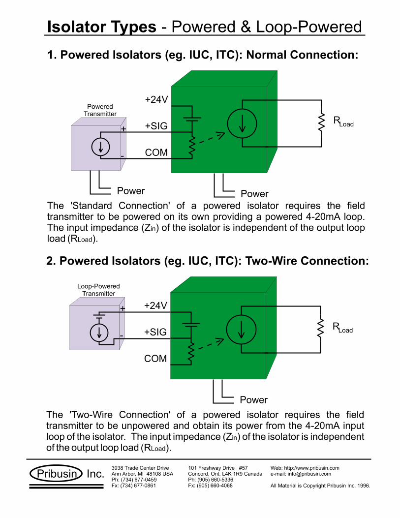
Isolator Types - Powered & Loop-Powered
+SIG
COM
+24V
Power
RLoad
2. Powered Isolators (eg. IUC, ITC): Two-Wire Connection:
Loop-PoweredTransmitter
+SIG
COM
+24V
Power Power
RLoad
1. Powered Isolators (eg. IUC, ITC): Normal Connection:
PoweredTransmitter
+
-
+
-
The 'Standard Connection' of a powered isolator requires the fieldtransmitter to be powered on its own providing a powered 4-20mA loop.The input impedance (Z ) of the isolator is independent of the output loopload (R ).
in
Load
The 'Two-Wire Connection' of a powered isolator requires the fieldtransmitter to be unpowered and obtain its power from the 4-20mA inputloop of the isolator. The input impedance (Z ) of the isolator is independentof the output loop load (R ).
in
Load
Pribusin Inc.101 Freshway Drive #57Concord, Ont. L4K 1R9 CanadaPh: (905) 660-5336Fx: (905) 660-4068
3938 Trade Center DriveAnn Arbor, MI 48108 USAPh: ( ) 677-0459Fx: ( ) 677-0861
734734 All Material is Copyright Pribusin Inc. 1996.
Web: http://www.pribusin.come-mail: [email protected]

Isolator Types - Powered & Loop-Powered
Power
R Load
4. Output-Loop-Powered Isolators (eg. TWI-MV22)
PoweredTransmitter
+
-
V Loop
Power
RLoad
3. Input-Loop-Powered Isolators (eg. TWI-22 & TWI-22-TB)
PoweredTransmitter +
-
+
-
4-20mA Loop Poweredfrom Transmitter
4-20mA Loop Poweredfrom Isolator
VLoop
VLoop
1.5V+
-
Zin
Z = 125 + Rin Load
In an Input Loop Powered Isolator the output loop is powered from the inputloop. This means that the load in the output loop (R ) is reflected ontothe input loop (Z ) plus some resistance for the isolator itself. Be sure theinput loop has enough drive. The isolator's loop drive is also limited.
Load
in
+
- +
-
+
-12V
In an Output Loop Powered Isolator the input comes from a powered firldtransmitter. A minimum of 12 Volts is required to operate the isolator. The -ve output is connected to the +ve input to the controller (R ). Sometimesthe common -ve connection between V and R is not even available atthe controller end.
Load
Loop Load
Pribusin Inc.101 Freshway Drive #57Concord, Ont. L4K 1R9 CanadaPh: (905) 660-5336Fx: (905) 660-4068
3938 Trade Center DriveAnn Arbor, MI 48108 USAPh: ( ) 677-0459Fx: ( ) 677-0861
734734 All Material is Copyright Pribusin Inc. 1996.
Web: http://www.pribusin.come-mail: [email protected]

LNG
100.0
T/CTransmitter 4-20mA Loop
Ground LoopGround Loop
LNG
100.0
T/CTransmitter
4-20mA Loop(Output)
Isolator4-20mA Loop
(Input)
Isolation Example #1 - Ground Loops
In a non-isolated system, a ground loop will distortthe signal by providing an unwanted connectionbetween the sensor and the signal loop.
In an isolated system the signal loop from thetransmitter is electrically separated from thesignal loop of the controller. Even if both loopsare grounded there is no electrical connectionbetween them. Besides preventing ground loops,this also reduces noise in many applications.
PLC / Controller
PLC / Controller
eg. Pribusin Part#:ITC-22, TWI-22-TBIUC-22
Pribusin Inc.101 Freshway Drive #57Concord, Ont. L4K 1R9 CanadaPh: (905) 660-5336Fx: (905) 660-4068
3938 Trade Center DriveAnn Arbor, MI 48108 USAPh: ( ) 677-0459Fx: ( ) 677-0861
734734 All Material is Copyright Pribusin Inc. 1996.
Web: http://www.pribusin.come-mail: [email protected]

LNG
100.0
T/CTransmitter 4-20mA Loop
P eot ee rnti eal Diff ncP eot ee rnti eal Diff nc
LNG
100.0
T/CTransmitter
4-20mA Loop(Output)
Isolator4-20mA Loop
(Input)
Isolation Example #2 - Ground Potentials
In a non-isolated system, different Groundpotentials can cause damage to the transmitterand/or controller by inducing high voltages orcurrents into the inputs.
In an isolated system the signal loop from thetransmitter is electrically separated from thesignal loop of the controller. Even if both loopsare at different potentials with respect to eachother there will be no damaging voltages orcurrents induced into the input of the controller orthe transmitter.
PLC / Controller
PLC / Controller
eg. Pribusin Part#:ITC-22, TWI-22-TBIUC-22
Pribusin Inc.101 Freshway Drive #57Concord, Ont. L4K 1R9 CanadaPh: (905) 660-5336Fx: (905) 660-4068
3938 Trade Center DriveAnn Arbor, MI 48108 USAPh: ( ) 677-0459Fx: ( ) 677-0861
734734 All Material is Copyright Pribusin Inc. 1996.
Web: http://www.pribusin.come-mail: [email protected]

LNG
100.0
FrequencyTransmitter
4-20mA Loop
LNG
100.0
FrequencyTransmitter
4-20mA Loop(Output)
Isolator4-20mA Loop
(Input)
Isolation Example #3 - Electrical Noise
In a non-isolated system, the input frequency cantransfer onto the signal output and distort the signal.Instruments may show erratic readings.
In an isolated system the input is filtered by the Isolator toprevent electrical noise from transferring to the output.Electrical noise filtered out includes signalsand signals.
Common ModeDifferential Mode
PLC / Controller
PLC / Controller
eg. Pribusin Part#:ITC-22, TWI-22-TBIUC-22
Pribusin Inc.101 Freshway Drive #57Concord, Ont. L4K 1R9 CanadaPh: (905) 660-5336Fx: (905) 660-4068
3938 Trade Center DriveAnn Arbor, MI 48108 USAPh: ( ) 677-0459Fx: ( ) 677-0861
734734 All Material is Copyright Pribusin Inc. 1996.
Web: http://www.pribusin.come-mail: [email protected]

Section 3
Alarm Trips
All Material contained in this manual is Copyright Pribusin Inc. 1996. Nopart of this manual may be used for any other purpose except for the sale ofPribusin Inc.'s product or the education of sales persons selling PribusinInc.'s product.
Pribusin Inc.

Setpoint Monitors - Alarming News
Setpoint Monitors have many different names. They are called Alarm Trips,Current Trips, Alarm Relays, Current Relays, and others. No matter whatthe name, they all perform one function: to signal an event that requiresaction to be taken. They all have a signal input and one or more relaycontact outputs that are used to perform actions.
Trip Setpoint
Deadband
High vs. Low Trip
- This is the signal level at which the relay contact isactivated to perform an action or indicate an event.
- This is the amount of at which the relaycontact de-activates.
- refers to an operating mode in which therelay contact becomes activated if the input level the TripSetpoint. refers to an operating mode in which the relay contactbecomes activated if the input level the Trip Setpoint.
signal differential
High Tripexceeds
Low Tripfalls below
0% Signal
100% Signal
Incre
asin
gS
ignalD
ecre
asin
gS
ignal SP
DB
ON
OFF
0% Signal
100% Signal
Incre
asin
gS
ignal D
ecre
asin
gS
ignal
SP DB
ON
OFF
High Trip Low Trip
Pribusin Inc.101 Freshway Drive #57Concord, Ont. L4K 1R9 CanadaPh: (905) 660-5336Fx: (905) 660-4068
3938 Trade Center DriveAnn Arbor, MI 48108 USAPh: ( ) 677-0459Fx: ( ) 677-0861
734734 All Material is Copyright Pribusin Inc. 1996.
Web: http://www.pribusin.come-mail: [email protected]

Setpoint Monitors - Setup Example
Pribusin's Setpoint Monitors have a unique variable adjustment method whichmakes them very easy to set up in the field. Each variable has a multi-turnpotentiometer and a test jack associated with it. Each test jack read a voltageof 0-5VDC for a variable setting of 0-100%.
Use the Following equations to set the various variables:
Deadband (%)100%
x 5 VDC = Test Jack Voltage
Delay (sec.)60 sec.
x 5 VDC = Test Jack Voltage
Setpoint (mA) - 4mA16 mA
x 5 VDC = Test Jack VoltageSetpoint:
Deadband:
Delay:
Example: A level probe delivers a 4-20mA signal of the level in a holding tank.The tank level is to be kept between a maximum level of 18mA and aminimum level of 7mA. A draining pump is to be turned on at 18mAand off at 7mA to accomplish this.
Setpoint (mA) - 4mA16 mA
x 5 VDC 18mA - 4mA16 mA x 5 VDC
=
= 0.875 x 5 VDC
= 4.375 VDC (Setpoint Test Jack)
18mA = 87.5% , 7mA = 18.75%
Deadband = 87.5% - 18.75% = 68.75%
= 0.6875 x 5 VDC = 3.4375 VDC (Deadband Test Jack)
Pribusin Inc.101 Freshway Drive #57Concord, Ont. L4K 1R9 CanadaPh: (905) 660-5336Fx: (905) 660-4068
3938 Trade Center DriveAnn Arbor, MI 48108 USAPh: ( ) 677-0459Fx: ( ) 677-0861
734734 All Material is Copyright Pribusin Inc. 1996.
Web: http://www.pribusin.come-mail: [email protected]

Section 4
Two-WireInstruments
All Material contained in this manual is Copyright Pribusin Inc. 1996. Nopart of this manual may be used for any other purpose except for the sale ofPribusin Inc.'s product or the education of sales persons selling PribusinInc.'s product.
Pribusin Inc.

Two-Wire Instruments - Theory of Operation
RLoop
VLoop
Two-Wire Instruments get their name from the 2 wires they use to get both powerfrom a controller and deliver a signal back to it. Other instruments typically use 4wires: 2 for power and 2 for the signal.
2-Wire Instruments work on 4-20mA loops ONLY !! They accomplish their taskby taking a small amount of power from the loop to run themselves and thenmodulate the current running through them to represent a signal proportional towhat they are measuring.
Typical 2-Wire Instruments are used for RTD, T/C, mV and isolation applicationswhere the sensing element requires little or no power.
T/C
eg. Pribusin Part#:TWI-TXX-TB, TWI-TXX
24 30 36 42 48 54 60
500
1812
750
1000
1250
1750
0
2000
2250
2400
1500
max = loop
20 mAR
load
V - 12 V
Operating
Region
V loop (VDC)
Rlo
ad
ma
x.
(Oh
ms)
250
2500Because 2-wire instruments take some powerfrom the loop, the amount of loop driveremaining depends on the power supply of theloop. The graph on the right shows themaximum loop load (R ) for given powersupplies. If the maximum load is exeededthere will not be enough power for the 2-wireinstrument. This graph is for Pribusin's TWI-XXX-TB series of instruments
Load
2-wire instruments come in isolated and non-isolated types. Isolated types are preferred asthey reduce the risk of ground loops and noiseinterferrence. Non-isolated types must be usedwith caution and only when the sensor isabsolutely isolated itself.
100.0
PLC / Controller
RLoop
VLoop
+24V
+Sig
Pribusin Inc.101 Freshway Drive #57Concord, Ont. L4K 1R9 CanadaPh: (905) 660-5336Fx: (905) 660-4068
3938 Trade Center DriveAnn Arbor, MI 48108 USAPh: ( ) 677-0459Fx: ( ) 677-0861
734734 All Material is Copyright Pribusin Inc. 1996.
Web: http://www.pribusin.come-mail: [email protected]

Section 5
Frequency
All Material contained in this manual is Copyright Pribusin Inc. 1996. Nopart of this manual may be used for any other purpose except for the sale ofPribusin Inc.'s product or the education of sales persons selling PribusinInc.'s product.
Pribusin Inc.

Frequency - The Up's and Down's of Mr. Hertz
Frequency is defined as a regularly ocurring event over a period of time. It ismeasured in Hertz (Hz) which is the count of these recurring event cycles in onesecond. In electronics, frequency is the fluctuation in voltage of a signal.
Sinusoidal - eg. AC House current
Square - eg. Rotary Flowmeters
Pulse Width Modulation - eg. Motor Drives
All Frequencies have 2 main identifying properties:
1. - The voltage difference between extreme levelsAmplitude
eg.12VDC
0VDCThe amplitude is 12 Volts
2. - The number of cycles per secondFrequency
eg.
1 2 3 4
1 second = 4cycles/second = 4Hz
There are many types of frequency:
Pribusin Inc.101 Freshway Drive #57Concord, Ont. L4K 1R9 CanadaPh: (905) 660-5336Fx: (905) 660-4068
3938 Trade Center DriveAnn Arbor, MI 48108 USAPh: ( ) 677-0459Fx: ( ) 677-0861
734734 All Material is Copyright Pribusin Inc. 1996.
Web: http://www.pribusin.come-mail: [email protected]

Use of Frequency - Application Examples
Example 2: Sometimes the speed of a motor must be monitored veryclosely and the above example would result in insufficientsignal resolution. Using a Pribusin Frequency WindowConverter allows a small portion of the frequency to beextracted and then converted to an analog signal.
Suppose a motor runs at 2000 RPM. It is to be monitoredover a range of 1900-2100 RPM.
IsolatedFrequencyTransmitter
MagneticPick-up
4-20mA
Using Pribusin's Isolated Frequency Converter IUC-7X-FRX serves a dual purpose by achieving the desiredconversion and isolating the input frequrency from theanalog output signal.
When converting frequency to ananalog signal it is important to notethat the output signal is zero-based. This means that afrequency of 0 Hz always results ina signal output of 0%. The upperfrequency limit is the onlyadjustment. This upper limitfrequency results in a 100%output signal.
Example 1: Frequency is quite often used as a speed indicator of amotor or a rotating vane of a flowmeter. Typically, thisfrequency cannot be use in its raw form and must usually beconverted to some sort of analog signal, ie. 4-20mA.
1900 2100 max. frequency0Input
Output
4 20
By setting up the Frequency Window Converter appropriately, asmall portion of frequency can be extracted and expanded into afull 4-20mA (or any other) analog output.
Pribusin Inc.101 Freshway Drive #57Concord, Ont. L4K 1R9 CanadaPh: (905) 660-5336Fx: (905) 660-4068
3938 Trade Center DriveAnn Arbor, MI 48108 USAPh: ( ) 677-0459Fx: ( ) 677-0861
734734 All Material is Copyright Pribusin Inc. 1996.
Web: http://www.pribusin.come-mail: [email protected]

Use of Frequency - Application Examples
Example 3: Some Natural Gas Consumption meters produce a burst ofpulses at a high rate. This rate is often too high for countersto measure.
A Pribusin Frequency Isolator with Buffer option can store upto 65535 incoming pulses at a fast rate and slowly pass themon to a slower counter or PLC input.
GasMeter
FrequencyIsolator& Buffer
Pribusin Inc.101 Freshway Drive #57Concord, Ont. L4K 1R9 CanadaPh: (905) 660-5336Fx: (905) 660-4068
3938 Trade Center DriveAnn Arbor, MI 48108 USAPh: ( ) 677-0459Fx: ( ) 677-0861
734734 All Material is Copyright Pribusin Inc. 1996.
Web: http://www.pribusin.come-mail: [email protected]

Section 6
RemoteTelemetry
All Material contained in this manual is Copyright Pribusin Inc. 1996. Nopart of this manual may be used for any other purpose except for the sale ofPribusin Inc.'s product or the education of sales persons selling PribusinInc.'s product.
Pribusin Inc.

Wireless Telemetry - The Invisible Connection
Wireless Radio Frequency (RF) telemetry offers a great advantage over othertelemetry methods by making use of a cheap and easily accessible transmissionmedium - AIR. When properly installed, wireless systems are very reliable andrequire little, if any maintenance. Using a license-free RF band eliminates the needfor obtaining a site license from the FCC.
�
�
�
�
�
2.4GHz RF Band is License FreeReliable Spread-Spectrum RadiosChannel-Hopping AlgorithmError Correction ProtocolAutomatic Re-Transmission on Error
Analog Inputs
Contact Inputs
Analog Outputs
Contact Outputs
Analog Inputs
Contact Inputs
Analog Outputs
Contact Outputs
Spread-Spectrum Technology
Spread-Spectrum Technology uses more than onefrequency to transmit data. The radios choose from over500 channels between 2.4000GHz and 2.4835GHz. ThisRF band has been set aside specifically for the license-free operation of spread-spectrum radios.
Channel-Hopping
Spread-spectrum radios use channel-hopping technology to make use of the many availablechannels. Radios will use one channel for only ¼ of a second before jumping to anotherchannel. This ensures that no one channel is ever occupied by one radio preventing anotherfrom using the channel. Each radio may use a different channel-hop-table thus allowing manyradios to share the same RF band without interfering with one another. If two foreign radiosshould happen to make use of the same channel, a collision will be detected by both radiosand they will each move onto a different channel and re-send their data.
Error-Correction & Re-Transmission
The radios use a comprehensive error checking algorithm to ensure that the transmitted datais indeed correct. If incorrect data was received, the receiver will instruct the sender to re-sendthe data until it has been received correctly. Since all data is transmitted in digital form there isno degradation in analog values when signal strength decreases. Forward error correctionalgorithms ‘repair’ any questionable data on the fly.
Wireless Telemetry - To see or not to see ...
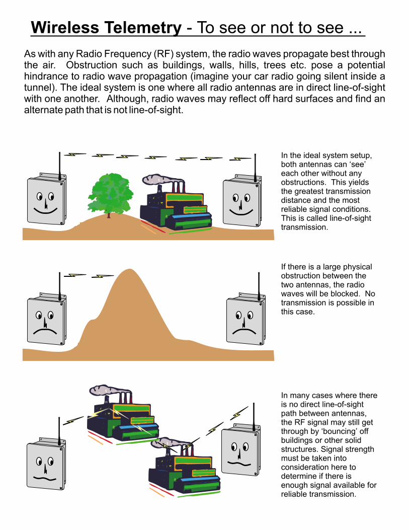
As with any Radio Frequency (RF) system, the radio waves propagate best throughthe air. Obstruction such as buildings, walls, hills, trees etc. pose a potentialhindrance to radio wave propagation (imagine your car radio going silent inside atunnel). The ideal system is one where all radio antennas are in direct line-of-sightwith one another. Although, radio waves may reflect off hard surfaces and find analternate path that is not line-of-sight.
In the ideal system setup,both antennas can ‘see’each other without anyobstructions. This yieldsthe greatest transmissiondistance and the mostreliable signal conditions.This is called line-of-sighttransmission.
If there is a large physicalobstruction between thetwo antennas, the radiowaves will be blocked. Notransmission is possible inthis case.
In many cases where thereis no direct line-of-sightpath between antennas,the RF signal may still getthrough by ‘bouncing’ offbuildings or other solidstructures. Signal strengthmust be taken intoconsideration here todetermine if there isenough signal available forreliable transmission.

Wireless Telemetry - Antennas & Cable
One of the most important components of any RF system is the antenna. This iswhere the radio waves are sent on their way to the other radio. There are manydifferent types of antennas for different applications. Ideally antennas are locatedoutdoors and typically on a mast that clears all surrounding obstructions. Besidestransmitting the radio waves, antennas can also act as ‘radio wave amplifiers’.
The cable that connects the antenna with the radio is equally important.Unfortunately, all cable poses a ‘resistance’ to the RF signal thereby limiting theamount of signal being transmitted by the antenna. Using low-loss coaxial cable andkeeping this cable length short are two important considerations.
Omni-Directional Antenna
An Omni-Directional antenna is a non-directional antenna. Itradiates equal amounts of radio wave energy in a sphericalpattern. Higher gain antennas radiate in a 360° pattern that isflattened on top and bottom and looks more like a donut.These antennas are ideal for a host site that has severalremote sites located in various directions. Top View Side View (with gain)
Panel Antenna
A panel antenna is a directional antenna that ‘focuses’the radio wave energy into a beam which is aimed outthe front of the antenna. Panel antennas have a highgain for greater distance transmissions and are greatfor a point-to-point RF system.
Top View
FrontFront
Up
Side View
YAGI Antenna
A Yagi antenna is a highly directionalantenna that produces a very narrowbeam of radio waves. These antennas
provide the greatest distance transmission and obstructionpenetration . Because of the narrow RF beam theyare more difficult to align.
capability
Top View Side View
Antenna Polarization
All antennas have a direction of polarization. This means thatradio waves leaving an antenna are ‘oriented’ by the polarizationof the antenna. Radio waves can only be received by anantenna of equal polarization. Directional antennas have apolarization marking (vertical or horizontal) and a directionarrow to indicate which way is UP. Omni-directional antennascan be mounted in any orientation so long as ALL antennas inthe system are mounted the same way.
Vertical Vertical Vertical
Horizontal

Wireless Telemetry - May I be Your Host ?
A simple telemetry system consists of just two devices: a local unit and a remoteunit. However, many times there may be several remote sites that have data to beexchanged with a single local site. This setup is referred to as a host-to-multipointsystem. An 8-channel RCI-800-RFM can act as a host for up to four 2-channel RCI-200-RFMs. If the RCI-200-RFMs are configured as single channel units, one RCI-800-RFM can host up to eight remotes.
Signals can be exchanged with all remotes in both directions just like in a point-to-point system.
AI#1,2 & DI#1,2
(to remote #1)
AI#3,4 & DI#3,4
(to remote #2)
AI#5,6 & DI#5,6
(to remote #3)
AI#7,8 & DI#7,8
(to remote #4)
AO#1,2 & DO#1,2
(from remote #1)
AO#3,4 & DO#3,4
(from remote #2)
AO#5,6 & DO#5,6
(from remote #3)
AO#7,8 & DO#7,8
(from remote #4)
AI#1,2 & DI#1,2
to hostAO#1,2 &DO#1,2
AO#1,2 & DO#1,2
( ) from hostAI#1,2 &DI#1,2( )
Remote #1
AI#1,2 & DI#1,2
to hostAO#7,8 &DO#7,8
AO#1,2 & DO#1,2
( ) from hostAI#7,8 &DI#7,8( )
Remote #3
AI#1,2 & DI#1,2
to hostAO#3,4 &DO#3,4
AO#1,2 & DO#1,2
( ) from hostAI#3,4 &DI#3,4( )
Remote #2
AI#1,2 & DI#1,2
to hostAO#7,8 &DO#7,8
AO#1,2 & DO#1,2
( ) from hostAI#7,8 &DI#7,8( )
Remote #4

Section 7
SampleApplications
All Material contained in this manual is Copyright Pribusin Inc. 1996. Nopart of this manual may be used for any other purpose except for the sale ofPribusin Inc.'s product or the education of sales persons selling PribusinInc.'s product.
Pribusin Inc.

Sample Applications - Go with the Flow
Measuring and controlling flows is a wide-spread applications field. Here aresome applications where Pribusin's instruments have excelled.
Example 1: The flow of waste-water over a weir is to be determined and usedto control a flow gate. The weir has a float with a sensor thatreturns a 4-20mA signal indicating the height of water over theweir.
IUC-XX-LNZ
4-20mA
By using a Pribusin Linearizer theheight signal from the heightsensor is converted to an actualflow signal indicating the amountof water flowing over the weir.
HeightSensor
Example 2: Using the above example as a base, we may need to find thetotal amount of water flowing over that weir (or in a pipe) over aperiod of, say, a day. This may be used for performance records,billing, etc.
HeightSensor
00001430
100.0
IUC-28-RIT
4-20mA
Using the IUC-28-RIT both functions of controlling the water flowand measuring it over a period of time can be accomplishedtogether. The IUC-28-RIT comes in a NEMA4 type enclosuremaking it ideal for locations exposed to high moisture andoccasional splash water.
3.5 DigitFlow Rate
8 DigitTotalizer
Pribusin Inc.101 Freshway Drive #57Concord, Ont. L4K 1R9 CanadaPh: (905) 660-5336Fx: (905) 660-4068
3938 Trade Center DriveAnn Arbor, MI 48108 USAPh: ( ) 677-0459Fx: ( ) 677-0861
734734 All Material is Copyright Pribusin Inc. 1996.
Web: http://www.pribusin.come-mail: [email protected]

Sample Applications - Displays of Truth
Most control applications never require operator intervention but in somecases it's important that an operator be able to verify the status of a process.For this, a display showing the process signal level can easily be added to theexisting circuitry.
Example 1: A flowmeter on a pipe measures the flow rate of a liquid andcontrols a pump. Under certain circumstances an operator mayhave to intervene and manually control the pump. But theoperator doesn't really know the flow rate under manual control.
100.0
PumpController
FlowmeterTWD-3.5
By using a Pribusin Two-Wire Display virtually no modifications are requiredin the loop other than splicing the display into the loop somewhere. Only 125ohms of additional load are placed into the loop which is easily handled bymost existing loops.
The display can be setup to display any range from 0-1999 complete with 3decimal points. This makes it very easy to display meanigfull data on acertain process.
100.0
PWD-3.5If not enough power is available in theloop to run a 2-wire display or if thereis no loop an alternative is the TWD-3.5 which is the powered version. Ithas a built-in 24VDC supply toprovide power to a field transmitter.
LN
120 VAC
4-20mA
Example 2:
Pribusin Inc.101 Freshway Drive #57Concord, Ont. L4K 1R9 CanadaPh: (905) 660-5336Fx: (905) 660-4068
3938 Trade Center DriveAnn Arbor, MI 48108 USAPh: ( ) 677-0459Fx: ( ) 677-0861
734734 All Material is Copyright Pribusin Inc. 1996.
Web: http://www.pribusin.come-mail: [email protected]

Sample Applications - Taming the PLC
Some PLC's have specialized inputs that can make it difficult to connect certaininstruments. The most frequently encountered problem is one where the PLCinput is designed to accept a 2-wire instrument only.
100.0
PLC / Controller
RLoop
VLoop
+24V
+Sig
Example 1: A PLC has only a 2-wire input with terminals for +24V and +Signal.A powered field transmitter supplies a powered 4-20mA loop and isto be connected to the PLC.
eg. Pribusin Part#:TWI-MV22-TB
100.0
PLC / Controller
RLoop
VLoop
+24V
+Sig
Power
+Sig.
COM
?
Power
+Sig.
COM
+
-
+
-
12V
PoweredField Transmitter
By using Pribusin's TWI-MV22-TB Isolator, the connection can beaccomplished while at the same time isolating the two loops. From thePLC side, the TWI-MV22-TB isolator looks like a 2-wire instrument.From the field transmitter side, the isolator looks just like another loopload.
RLoad
(R = 2.5 Ohms)Load
The PLC has no external connection for the signal common. As a resulta powered 4-20mA loop cannot be connected because no completecurrent loop can be established without a common.
Pribusin Inc.101 Freshway Drive #57Concord, Ont. L4K 1R9 CanadaPh: (905) 660-5336Fx: (905) 660-4068
3938 Trade Center DriveAnn Arbor, MI 48108 USAPh: ( ) 677-0459Fx: ( ) 677-0861
734734 All Material is Copyright Pribusin Inc. 1996.
Web: http://www.pribusin.come-mail: [email protected]

Sample Applications - Power Measurement
Various applications require the monitoring of power consumption. In amotor, for example, current draw is an indication of torque load. Toprolong the life of the motor, a limit on the torque load may have to beadhered to. Other applications may require the monitoring of AC linevoltage or total power comsumption (watts).
Average vs. RMS
For most loads an average value of voltage or current is sufficient.Applications such as motors, incandescent lights, heaters and linear powersupplies have almost pure sine wave power waveforms. The average valueprovides a good indication of the actual value.
In applications where power switching is used, the resulting waveforms maynot be sinusoidal. An average value would provide a poor representation ofthe actual value. A much better actual value comes from the Root-Mean-Square (RMS) of the waveform.
Pure-sine Wave: use Averaging Switched Wave: use RMS
Voltage: When measuring voltages greater than 150VAC a potentialtransformer (P.T.) is required to reduce the voltage to around120VAC.
Current: When measuring currents in excess of 5 Amps, a currenttransformer (C.T.) is required to reduce the current to a value ofaround 5 Amps.
CAUTION:
Current Transformers can be very dangerous if not handled correctly. Ifthe Secondary side is disconnected without first shorting the terminalstogether, dangerously high voltages will result. These voltages can beseveral 1000 volts and can be deadly.
Pribusin Inc.101 Freshway Drive #57Concord, Ont. L4K 1R9 CanadaPh: (905) 660-5336Fx: (905) 660-4068
3938 Trade Center DriveAnn Arbor, MI 48108 USAPh: ( ) 677-0459Fx: ( ) 677-0861
734734 All Material is Copyright Pribusin Inc. 1996.
Web: http://www.pribusin.come-mail: [email protected]