training document for comprehensive automation … · notes on programming the simatic s7-300 with...
TRANSCRIPT

Automation and Drives - SCE
T I A Training Document Page 1 of 48 Module
A3 Issue date: 02/2008 'Startup’ PLC Programming with STEP 7
Training Document for Comprehensive Automation
Solutions
Totally Integrated Automation (T I A)
MODULE A3
'Startup' PLC Programming with STEP 7

Automation and Drives - SCE
T I A Training Document Page 2 of 48 Module
A3 Issue date: 02/2008 'Startup’ PLC Programming with STEP 7
This document has been written by Siemens AG for training purposes for the project entitled "Siemens Automation Cooperates with Education (SCE)". Siemens AG accepts no responsibility for the correctness of the contents. Transmission, use or reproduction of this document is only permitted within public training and educational facilities. Exceptions require the prior written approval of Siemens AG (Mr. Michael Knust [email protected]). Offenders will be liable for damages. All rights, including the right to translate the document, are reserved, particularly if a patent is granted or utility model is registered. We would like to thank the following: Michael Dziallas Engineering, the teachers at vocational schools, and all others who helped to prepare this document.

Automation and Drives - SCE
T I A Training Document Page 3 of 48 Module
A3 Issue date: 02/2008 'Startup’ PLC Programming with STEP 7
PAGE: 1. Foreword ............................................................................................................... 5 2. Notes on Programming the SIMATIC S7-300 with STE P 7............................... 7 2.1 SIMATIC S7-300 Automation System.................................................................... 7 2.2 STEP 7 Programming Software............................................................................. 7 3. Installation of the STEP 7 Software ................................................................... 8 4. Setting the Programming Interface (PC Adapter USB) .................................... 9 5. What is a PLC and what are PLCs used for? .................................................... 14 5.1 What does the term PLC mean? ........................................................................... 14 5.2 How does the PLC control the process?................................................................ 14 5.3 From where does the PLC obtain information on process states? ........................ 15 5.4 What is the difference between NC switches and NO switches? .......................... 15 5.5 How does the PLC decide which individual inputs/outputs it sends signals to? .... 16 5.6 How is the program executed in the PLC? ............................................................ 17 5.7 What do logic operations look like in the PLC program?....................................... 18 5.7.1 AND logic operation ............................................................................................... 18 5.7.2 OR logic operation ................................................................................................. 20 5.7.3 Negation................................................................................................................. 21 5.8 How is the PLC program created? How is it placed in the memory of the PLC?... 22 6. Structure and Operator Control of the SIMATIC S7 -300 .................................. 23 7. Task Example ....................................................................................................... 26 8. Setting Up a STEP 7 Project ............................................................................... 27 9. Writing the STEP 7 Program in Function Block Dia gram (FBD) ..................... 35 10. Testing the STEP 7 Program in the CPU ........................................................... 47

Automation and Drives - SCE
T I A Training Document Page 4 of 48 Module
A3 Issue date: 02/2008 'Startup’ PLC Programming with STEP 7
The following symbols provide guidance through this module: Information Installation Programming Task example Notes

Automation and Drives - SCE
T I A Training Document Page 5 of 48 Module
A3 Issue date: 02/2008 'Startup’ PLC Programming with STEP 7
Foreword Notes Installation Interface What is a PLC? Structure of S7-300 Task example Project Program Testing
1. FOREWORD
In terms of its contents, module A3 belongs to the teaching unit entitled 'Basic Principles of STEP 7 Programming' and is intended to serve as a quick introduction to STEP 7 programming.
Learning Objective: In this module, the reader learns how to program a programmable logic controller (PLC) with the STEP 7 programming tool. The module explains the fundamentals and, based on the following steps, demonstrates the procedure, using a detailed example:
• Installation of the software and setup of the programming interface
• Explanation of what a PLC is and how it works
• Structure and operator control of the SIMATIC S7-300 programmable logic controller
• Creation of a program as an example
• Loading and testing of the program example Requirements: The following knowledge is a precondition for successful utilization of this module:
• Knowledge in the use of Windows
Basic Principles of STEP 7 Programming 2 to 3 days Module A
Industrial Field Bus Systems 2 to 3 days Module D
Further Functions of STEP 7 Programming 2 to 3 days Module B
Process Visualization 2 to 3 days Module F
Progamming Languages 2 to 3 days Module C
IT Communication with SIMATIC S7 2 to 3 days Module E
Plant Simulation with SIMIT SCE 1 to 2 days Module G
Frequency Converter at SIMATIC S7 2 to 3 days Module H

Automation and Drives - SCE
T I A Training Document Page 6 of 48 Module
A3 Issue date: 02/2008 'Startup’ PLC Programming with STEP 7
Foreword Notes Installation Interface What is a PLC? Structure of S7-300 Task example Project Program Testing
Hardware and software needed 1 PC, operating system Windows 2000 Professional starting with SP4 / XP Professional starting with SP1 / Server 2003 with 600 MHz and 512 RAM, free hard disk memory approx. 650 to 900 MB, MS Internet Explorer 6.0 2 Software: STEP7 V 5.4 3 MPI interface for the PC (e.g. PC adapter for USB) 4 SIMATIC S7-300 PLC with at least one digital input module and one digital output module. The inputs must be taken out to a control panel. Configuration example: - Power supply unit: PS 307 2A - CPU: CPU 314 - Digital inputs: DI 16x DC24V - Digital outputs: DO 16x DC24V/0.5 A
1 PC
2 STEP7
4 S7-300
3 PC Adapter USB

Automation and Drives - SCE
T I A Training Document Page 7 of 48 Module
A3 Issue date: 02/2008 'Startup’ PLC Programming with STEP 7
Foreword Notes Installation Interface What is a PLC? Structure of S7-300 Task example Project Program Testing
2. NOTES ON PROGRAMMING THE SIMATIC S7-300 WITH STEP 7
2.1 SIMATIC S7-300 AUTOMATION SYSTEM
The SIMATIC S7-300 automation system is a modular miniature control system for the lower and medium performance level. There is a comprehensive range of modules for optimum adaptation to the automation task in hand. The S7 controller consists of a power supply unit, a CPU and input/output modules (I/O modules). When necessary, communication processors and function modules are used for special tasks such as stepper motor control. The programmable logic controller (PLC) monitors and controls a machine or a process with the S7 program. In the S7 program, signals are sent to the I/O modules by means of the input (I) and output (Q) addresses. The system is programmed with the STEP 7 software STEP 7.
2.2 STEP 7 PROGRAMMING SOFTWARE
The STEP 7 software is the programming tool for the following automation systems:
- SIMATIC S7-300
- SIMATIC S7-400
- SIMATIC WinAC
With STEP 7, the following functions can be used for automating a plant:
- Configuration and parameterization of the hardware
- Definition of communication modes
- Programming
- Testing, commissioning and servicing
- Documentation, archiving
- Operating/diagnostic functions
All functions are supported by a detailed online Help system.

Automation and Drives - SCE
T I A Training Document Page 8 of 48 Module
A3 Issue date: 02/2008 'Startup’ PLC Programming with STEP 7
Foreword Notes Installation Interface What is a PLC? Structure of S7-300 Task example Project Program Testing
3. INSTALLATION OF THE STEP 7 SOFTWARE
There are two versions of STEP 7: - STEP 7 Professional Basic Version contains the options S7-SCL, S7-GRAPH and S7-PLCSIM.
This software package must be authorized. - STEP 7 Software for Students contains the options S7-SCL, S7-GRAPH and S7-PLCSIM. This
software package must be authorized and can then be used for 365 days. STEP 7 is supplied on CD-ROM. STEP 7 Professional includes a floppy disk containing a license key (authorization) which has to be transferred to the PC. Without this license key, STEP 7 cannot be used. It is also possible to retransfer this license key to the floppy disk so that it can be used on another PC. Starting with STEP 7 Professional V5.3 and higher, this license can also be administrated via a network. For instructions on installation and transfer of the license keys, please refer to Module A2 – Installation of STEP 7 V5.x / Handling the Authorization. To install STEP 7, perform the following steps: 1. Insert the STEP 7 CD in the CD-ROM drive.
2. The setup program is now started automatically. If not, start it by double clicking on the file → setup.exe . The setup program guides you through the entire installation process for the STEP 7 software.
3. To use STEP 7 Professional, a license key (authorization) -which means, the right to use the software- is needed on your computer. You have to transfer this key from the authorization floppy disk to your computer. This is done at the end of the installation. In a dialog box, the setup program asks you whether you want to carry out the authorization. If you select 'Yes' , you only have to insert the authorization floppy disk and the authorization (license key) will be transferred to your computer.
Automation and Drives - SCE
T I A Training Document Page 9 of 48 Module
A3 Issue date: 02/2008 'Startup’ PLC Programming with STEP 7
Foreword Notes Installation Interface What is a PLC? Structure of S7-300 Task example Project Program Testing
4. SETTING THE PROGRAMMING INTERFACE (PC ADAPTER US B)
In order to program a SIMATIC S7-300 from a PC, a programming device or a laptop, an MPI connection is needed. MPI is the abbreviation for Multi Point Interface and is a communication interface for up to 32 nodes. The interface is used for programming and operator control with an HMI, and also for data exchange between SIMATIC S7 CPUs. Each CPU of the SIMATIC S7-300 has such an integrated interface. There are different ways of connecting a PC, a programming device or laptop to the MPI: - Integrated ISA communication processors for the programming device - ISA communication processors for the PC (e.g. MPI-ISA card) - PCI communication processors for the PC (e.g. CP5611) - PCMCIA communication processors for the laptop (e.g. CP5511) - PC adapter for communication via the serial interface of a PC or laptop - PC adapter USB for communicating via a USB interface of the PC or laptop The steps below describe the setting and parameter assignment of a PC adapter USB for a PC. A precondition for this is that the driver software included with the PC adapter USB has been installed on the PC. When you insert the "PC Adapter USB V1.2" CD into the CD-ROM drive, the setup
program is started automatically. If not, start it by double clicking on the file → setup.exe . The setup program will guide you through the entire installation process. Once this has been done, proceed as follows:
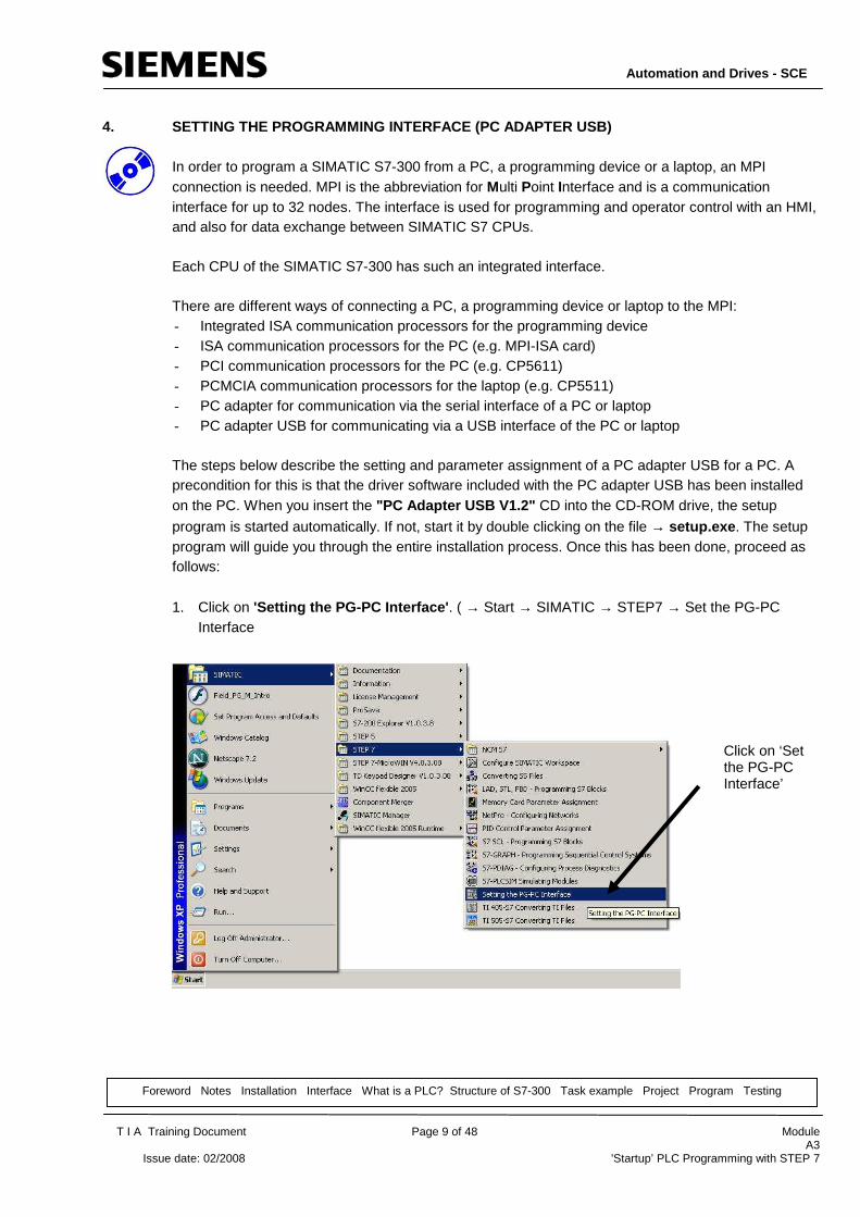
1. Click on 'Setting the PG-PC Interface' . ( → Start → SIMATIC → STEP7 → Set the PG-PC Interface
Click on ‘Set the PG-PC Interface’

Automation and Drives - SCE
T I A Training Document Page 10 of 48 Module
A3 Issue date: 02/2008 'Startup’ PLC Programming with STEP 7
Foreword Notes Installation Interface What is a PLC? Structure of S7-300 Task example Project Program Testing
2. 'Select' the module that is available as the MPI interface. ( → Select )
3. If the desired module is not displayed on the right-hand side under 'Installed' , select this module;
for example, 'PC Adapter' , and 'Install' it (→ PC Adapter → Install)
Click on ‘PC Adapter’ Click on ‘Install’
Click on ‘Select'

Automation and Drives - SCE
T I A Training Document Page 11 of 48 Module
A3 Issue date: 02/2008 'Startup’ PLC Programming with STEP 7
Foreword Notes Installation Interface What is a PLC? Structure of S7-300 Task example Project Program Testing
4. Confirm with 'Yes' if STEP 7 is to used the new interface you entered for 'Online' access. After
doing this, 'Close' the window for selecting the interface (→ Yes → Close )
5. Select 'Properties' of the 'PC Adapters(MPI)' ( → PC Adapter(MPI) → Properties)
Click on ‘Yes’
Click on ‘Close'
Click on ‘PC Adapter (MPI)'
Click on ‘Properties'

Automation and Drives - SCE
T I A Training Document Page 12 of 48 Module
A3 Issue date: 02/2008 'Startup’ PLC Programming with STEP 7
Foreword Notes Installation Interface What is a PLC? Structure of S7-300 Task example Project Program Testing
6. Select 'USB' for the PC Adapter USB at the 'Connection to' field. For a serial PC adapter, select 'COM Port’ and 'Transmission Rate' of the serial interface.
Note: For a serial PC adapter, the transmission rate for the PC adapter must also be adjusted accordingly. Old-generation PC adapters (so-called PC/MPI cables) are only able to process the slower transmission rate of 19200 bit/s. 7. Enter 'MPI Address', 'Timeout', 'Transmission Rate' and 'Highest Station Address' .
Note: It is recommended to accept the default values!
8. Accept settings ( → OK → OK ).
Baud rate!
Highest station address
Timeout!
MPI address of the PC/PG!
COM port
Transmission rate
USB

Automation and Drives - SCE
T I A Training Document Page 13 of 48 Module
A3 Issue date: 02/2008 'Startup’ PLC Programming with STEP 7
Foreword Notes Installation Interface What is a PLC? Structure of S7-300 Task example Project Program Testing
9. In order to test the settings, start the 'SIMATIC Manager' by double clicking on the icon. ( →
SIMATIC Manager)
10. Then, plug the connector that comes from the MPI interface of the PC into the MPI interface of the CPU and switch on the voltage supply of the PLC. The MPI interface is a 9-pin D-Sub socket located behind the front flap of the CPU.
11. If you now click on the ' – Accessible Stations' button, the following window appears with a folder for the accessible MPI stations -provided all the parameters have been correctly selected. The window also shows the MPI address of the connected CPU. The default setting of this address is 2. If several PLCs are connected or CPs/FMs are plugged into the connected PLCs,
several MPI addresses are shown here. ( → )

Automation and Drives - SCE
T I A Training Document Page 14 of 48 Module
A3 Issue date: 02/2008 'Startup’ PLC Programming with STEP 7
Foreword Notes Installation Interface What is a PLC? Structure of S7-300 Task example Project Program Testing
5. WHAT IS A PLC AND WHAT ARE PLCS USED FOR?
5.1 WHAT DOES THE TERM PLC MEAN?
PLC is the abbreviation for programmable logic controller. This is a device that controls a process (e.g. a printing machine for printing newspapers, a filling system for filling cement into containers, a press for pressing molded-plastic components etc. ...). The process is controlled according to the instructions of a program stored in a memory of the PLC.
5.2 HOW DOES THE PLC CONTROL THE PROCESS? The PLC controls the process as follows: a control voltage of 24 V for example, coming from the PLC's terminals called outputs , is applied to so-called actuators . As a result, motors can be switched on and off, valves can be opened and closed, or lamps can be turned on and off.
M
M
0V
24V
The outputs of the PLC control the actuators by switching the control voltage off/off.
PLC
Machine
Program with instructions
Memory
Program loaded into the memory of the PLC......
.... controls the machine
PLC
Outputs
Lamp lights up
Lamp does not light up
Automation and Drives - SCE
T I A Training Document Page 15 of 48 Module
A3 Issue date: 02/2008 'Startup’ PLC Programming with STEP 7
Foreword Notes Installation Interface What is a PLC? Structure of S7-300 Task example Project Program Testing
5.3 FROM WHERE DOES THE PLC OBTAIN INFORMATION ON P ROCESS STATES?
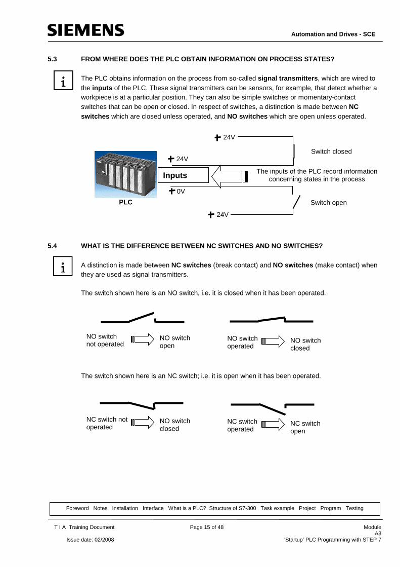
The PLC obtains information on the process from so-called signal transmitters , which are wired to the inputs of the PLC. These signal transmitters can be sensors, for example, that detect whether a workpiece is at a particular position. They can also be simple switches or momentary-contact switches that can be open or closed. In respect of switches, a distinction is made between NC switches which are closed unless operated, and NO switches which are open unless operated.
5.4 WHAT IS THE DIFFERENCE BETWEEN NC SWITCHES AND NO SWITCHES? A distinction is made between NC switches (break contact) and NO switches (make contact) when they are used as signal transmitters. The switch shown here is an NO switch, i.e. it is closed when it has been operated. The switch shown here is an NC switch; i.e. it is open when it has been operated.
24V
24V
0V
The inputs of the PLC record information concerning states in the process
PLC
Inputs
Switch closed
Switch open
24V
NO switch not operated
NO switch open
NO switch operated
NO switch closed
NC switch not operated
NO switch closed
NC switch operated
NC switch open

Automation and Drives - SCE
T I A Training Document Page 16 of 48 Module
A3 Issue date: 02/2008 'Startup’ PLC Programming with STEP 7
Foreword Notes Installation Interface What is a PLC? Structure of S7-300 Task example Project Program Testing
5.5 HOW DOES THE PLC DECIDE WHICH INDIVIDUAL INPUTS /OUTPUTS IT SENDS SIGNALS TO?
Specifying a particular input or output within the program is called addressing. The inputs and outputs of the PLCs are placed together (usually in groups of eight) to form digital input or digital output modules. These groups of eight are called bytes and each such group is given a number as its so-called byte address . To enable a signal to be sent to an individual input or output within a byte, each byte is broken down into individual bits . These are numbered bit 0 to bit 7. This number is the bit address . The PLC shown here has input bytes 0 and 1 as well as output bytes 4 and 5.
In order for a signal to be sent to the fifth input from the top, for example, the following address must be specified:
I 0 . 4
I identifies the address type as an input, 0 is the byte address and 4 is the bit address.
Byte address and bit address are always separated by a point. Note: A 4 is used as the bit address for the fifth input because counting starts at 0. In order for a signal to be sent to the output at the very bottom, the following address must be specified:
Q 5 . 7
Q identifies the address type as an output, 5 is the byte address and 7 is the bit address.
Byte address and bit address are always separated by a point. Note: A 7 is used as the bit address for the output at the very bottom, because counting starts at 0.
Digital input module Byte 0
Bit 0 to 7
Digital output module Byte 5
Bit 0 to 7
Digital output module Byte 4
Bit 0 to 7
Digital input module Byte 1
Bit 0 to 7
Automation and Drives - SCE
T I A Training Document Page 17 of 48 Module
A3 Issue date: 02/2008 'Startup’ PLC Programming with STEP 7
Foreword Notes Installation Interface What is a PLC? Structure of S7-300 Task example Project Program Testing
5.6 HOW IS THE PROGRAM EXECUTED IN THE PLC?
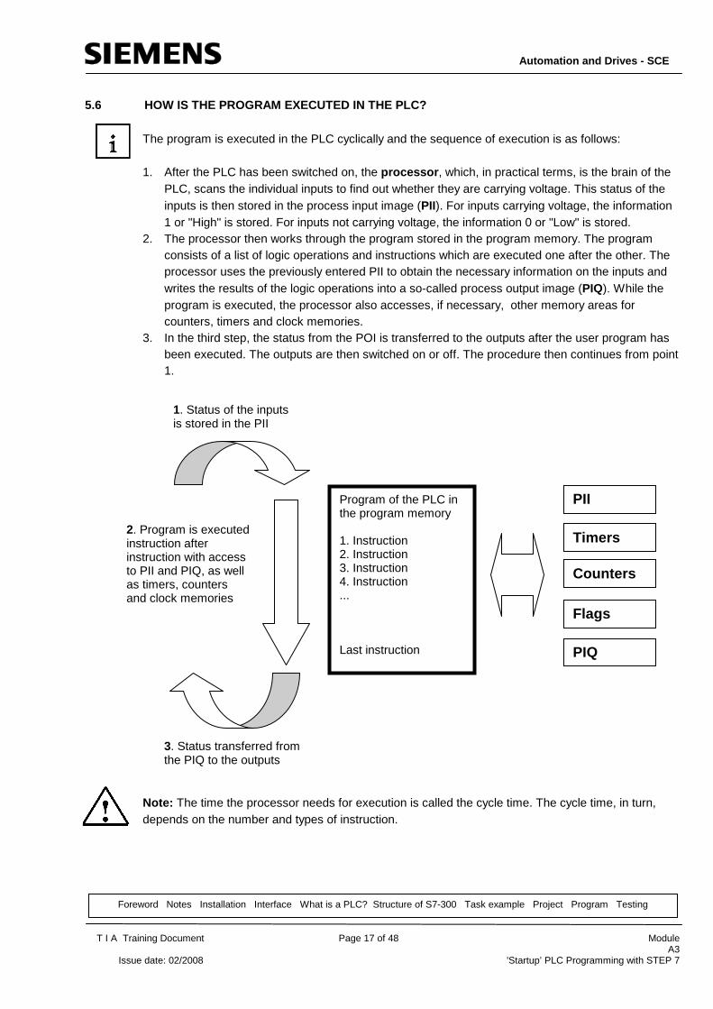
The program is executed in the PLC cyclically and the sequence of execution is as follows: 1. After the PLC has been switched on, the processor , which, in practical terms, is the brain of the
PLC, scans the individual inputs to find out whether they are carrying voltage. This status of the inputs is then stored in the process input image (PII). For inputs carrying voltage, the information 1 or "High" is stored. For inputs not carrying voltage, the information 0 or "Low" is stored.
2. The processor then works through the program stored in the program memory. The program consists of a list of logic operations and instructions which are executed one after the other. The processor uses the previously entered PII to obtain the necessary information on the inputs and writes the results of the logic operations into a so-called process output image (PIQ). While the program is executed, the processor also accesses, if necessary, other memory areas for counters, timers and clock memories.
3. In the third step, the status from the POI is transferred to the outputs after the user program has been executed. The outputs are then switched on or off. The procedure then continues from point 1.
Note: The time the processor needs for execution is called the cycle time. The cycle time, in turn, depends on the number and types of instruction.
Program of the PLC in the program memory 1. Instruction 2. Instruction 3. Instruction 4. Instruction ... Last instruction
1. Status of the inputs is stored in the PII
2. Program is executed instruction after instruction with access to PII and PIQ, as well as timers, counters and clock memories
3. Status transferred from the PIQ to the outputs
PII
Timers
Counters
Flags
PIQ

Automation and Drives - SCE
T I A Training Document Page 18 of 48 Module
A3 Issue date: 02/2008 'Startup’ PLC Programming with STEP 7
Foreword Notes Installation Interface What is a PLC? Structure of S7-300 Task example Project Program Testing
5.7 WHAT DO LOGIC OPERATIONS LOOK LIKE IN THE PLC P ROGRAM?
Logic operations are used to define the conditions for switching an output on/off. In the PLC program, they can be written in the following programming languages: ladder logic (LAD ), function block diagram (FBD) or statement list (STL). For purpose of clarity, we have restricted ourselves here to FBD. There is a large number of different logic operations that can be used in PLC programs. AND and OR operations and NEGATION of an input, however, are the most frequently used and are therefore explained here briefly with some examples. Note: Clear information on other logic operations can be obtained easily from the online Help system.
5.7.1 THE 'AND' LOGIC OPERATION Example of an AND logic operation: A lamp is supposed to light up when two NO switches are operated simultaneously. Circuit diagram: Explanation: The lamp lights up exactly when both switches are operated. When the S1 switch and the S2 switch are operated, the lamp, E1, lights up.
24V
M
S1 S2
E1

Automation and Drives - SCE
T I A Training Document Page 19 of 48 Module
A3 Issue date: 02/2008 'Startup’ PLC Programming with STEP 7
Foreword Notes Installation Interface What is a PLC? Structure of S7-300 Task example Project Program Testing
Wiring of the PLC: In order to implement this logic in a PLC program, both switches must, of course, be connected to the inputs of the PLC. Here, S1 is wired to input I 0.0 and S2 is wired to input I 0.1. In addition, the lamp E1 must have been connected to an output, e.g. Q 4.0. AND logic operation in the FBD: In the function block diagram (FBD), the AND logic operation is programmed by means of a graphic representation and looks like this:
& =
M
24V
PLC
Inputs
Switch S1
Switch S2
I 0.0
Q 4.0 Outputs
Lamp E1 is supposed to light up when switches S1 and S2 are operated.
24V
I 0.1
Q 4.0
I 0.1
I 0.0
Inputs of the AND logic operation. Here, there can be more than 2 inputs
Output to which the signal is assigned
Graphic representation of the AND logic operation
Assignment of the result of the logic operation

Automation and Drives - SCE
T I A Training Document Page 20 of 48 Module
A3 Issue date: 02/2008 'Startup’ PLC Programming with STEP 7
Foreword Notes Installation Interface What is a PLC? Structure of S7-300 Task example Project Program Testing
5.7.2 'OR' LOGIC OPERATION
Example of an OR logic operation: A lamp is supposed to light up when one NO switch or both NO switches are operated. Circuit diagram: Explanation: The lamp lights up exactly when one switch or both switches are operated. In other words, the lamp, E1, lights up when switch S1 or switch S2 is operated. Wiring of the PLC: In order to implement this logic in a PLC program, both switches must, of course, be connected to inputs of the PLC. In this case, S1 is wired to input I 0.0 and S2 is wired to input I 0.1. In addition, the lamp, E1, must be connected to an output, e.g. Q 4.0.
M
24V
M
S1
S2
E1
24V
PLC
Inputs
Switch S1
Switch S2
I 0.0
Q 4.0 Outputs
Lamp E1 is supposed to light up when switch S1 or S2 is operated.
24V
I 0.1
24V

Automation and Drives - SCE
T I A Training Document Page 21 of 48 Module
A3 Issue date: 02/2008 'Startup’ PLC Programming with STEP 7
Foreword Notes Installation Interface What is a PLC? Structure of S7-300 Task example Project Program Testing
OR logic operation in the FBD: In the function block diagram (FBD), the OR logic operation is programmed by means of a graphic representation and looks like this:
5.7.3 NEGATION In logic operations, it is frequently necessary for the PLC to scan whether an NO switch has NOT been operated or whether an NC switch has been operated and thus ensure that no voltage is being applied to the corresponding input. This is done by programming a negation at the input of the AND or OR logic operation. In the function block diagram (FBD), the negation of an input at an AND logic operation is programmed by means of the following graphic representation: Here, the output Q 4.0 has voltage applied to it only if I 0.0 is not wired and I 0.1 is wired.
= Q 4.0
I 0.1
I 0.0
Inputs of the OR logic operation. Here, there can be more than 2 inputs
Output to which the signal is assigned
Graphic representation of the OR logic operation
Assignment of the result of the logic operation
& = Q 4.0
I 0.1
I 0.0
Input of the AND logic operation which is to be negated
Graphic representation of the negation
>

Automation and Drives - SCE
T I A Training Document Page 22 of 48 Module
A3 Issue date: 02/2008 'Startup’ PLC Programming with STEP 7
Foreword Notes Installation Interface What is a PLC? Structure of S7-300 Task example Project Program Testing
5.8 HOW IS THE PLC PROGRAM CREATED? HOW IS IT PLACE D IN THE MEMORY OF THE PLC?
The PLC program is created with the STEP 7 software on a PC, where it is stored temporarily. After the PC has been connected to the MPI interface of the PLC, the program can be loaded into the memory of the PLC with a loading function. Note: The exact procedure is described step by step in sections 8 to 10.
PC with STEP 7
S7-300 PLC
PC Adapter
1. Create PLC program with STEP 7 on PC.
2. Connect PC to MPI interface of the PLC.
3. Load program from PC into the memory of the PLC.

Automation and Drives - SCE
T I A Training Document Page 23 of 48 Module
A3 Issue date: 02/2008 'Startup’ PLC Programming with STEP 7
Foreword Notes Installation Interface What is a PLC? Structure of S7-300 Task example Project Program Testing
6. STRUCTURE AND OPERATOR CONTROL OF THE SIMATIC S7 -300
Range of modules: The SIMATIC S7-300 is a modular automation system with the following range of modules: - CPU modules (CPU) with different performance levels, sometimes with integrated inputs/outputs
(e.g.CPU314C) or integrated PROFIBUS interface (e.g. CPU315-2DP) - Power supply modules (PS) with 2 A, 5 A, or 10 A - Interface modules (IM) for multi-tier SIMATIC S7-300 - Signal modules (SM) for digital and analog inputs and outputs - Function modules (FM) for special functions (e.g. stepper motor control) - Communication processors (CP) for networking
Note: For this training module, only a power supply module, any CPU and a digital input module and a digital output module are needed.
PS: Power supply e.g. PS307 2A
CPU: Central processing unit e.g. CPU 314
IM: Interface module for multi-tier design e.g. IM360
FM: Function module servomotor PID control e.g. FM354 F
CP: Communication processors PROFIBUS DP Industrial Ethernet e.g. CP342-5
SM: Signal modules DI/DO AI/AO e.g. SM323

Automation and Drives - SCE
T I A Training Document Page 24 of 48 Module
A3 Issue date: 02/2008 'Startup’ PLC Programming with STEP 7
Foreword Notes Installation Interface What is a PLC? Structure of S7-300 Task example Project Program Testing
Important elements of the voltage supply and the CP U:
MPI interface: Each CPU has an MPI interface for connecting the programming cable (e.g. PC Adapter for USB). This interface is behind a flap on the front of the CPU.
Mode selector: Each CPU has a mode selector for changing between operating modes. It is usually in the form of a key switch that can also be pulled out in the operating modes RUN and STOP. The following operating modes are possible:
Note: With the latest series of CPUs, i.e. CPU31xC, this switch is in the form of a toggle switch. With the new CPUs, PG functions in the write mode are also allowed in RUN.
RUN-P: Program is being executed; all PG functions are allowed RUN: Program is being executed; only PG functions in the read mode are allowed STOP: Program is not being executed; all PG functions are allowed MRES: With this position, you can reset the memory as described below
Memory card if required
Signal modules
Status displays
Main voltage selector switch
ON/OFF switch
Mains connection
Battery if necessary MPI interface
Mode selector
CPU Power supply

Automation and Drives - SCE
T I A Training Document Page 25 of 48 Module
A3 Issue date: 02/2008 'Startup’ PLC Programming with STEP 7
Foreword Notes Installation Interface What is a PLC? Structure of S7-300 Task example Project Program Testing
Memory reset: A memory reset deletes all the user data on the CPU but not on the memory card or micro memory card. A memory reset should be carried out once before programming is started. This is done in the following 3 steps:
The STOP display flashes for approximately 3 seconds and then shows continuous light again. Everything OK; Memory of CPU has been reset .
Move the mode selector back to the STOP position and, after 2 seconds, move it to the MRES position again.
3
The STOP display goes out and lights up again after approximately 3 seconds. If the CPU is a new one, wait until the STOP display lights up a second time. N.B.: The maximum time allowed between step 2 and step 3 is 3 seconds.
Move the mode selector to the MRES position and hold it in this position (approx. 3 seconds) until the STOP display lights up again.
2
STOP display lights up Move the mode selector to the STOP position. 1
Result Execution Step

Automation and Drives - SCE
T I A Training Document Page 26 of 48 Module
A3 Issue date: 02/2008 'Startup’ PLC Programming with STEP 7
Foreword Notes Installation Interface What is a PLC? Structure of S7-300 Task example Project Program Testing
7. TASK EXAMPLE
For our first STEP 7 program, a simple task is to be solved. A press with a protection cage is only to be activated with an S1 START pushbutton switch when the cage is in the closed position. This status is monitored with a B0 cage sensor. If this is the case, a 5/2 M0 way valve for the pressing cylinder is triggered for exactly 10 seconds so that a plastic molding can be pressed. For safety reasons, the press is to be raised again when the S1 start pushbutton switch is released or the B0 cage sensor no longer responds. Assignment list: Address Symbol Comments I 0.0 B0 Cage sensor I 0.1 S1 Start pushbutton switch Q 4.0 M0 5/2 way valve for pressing cylinder
5/2 way valve controls the pressing cylinder. The cylinder is to be extended until the M0 output is triggered.
S1 pushbutton switch for starting the pressing process
B0 sensor detects whether the protection cage is down.
Protection cage for preventing injury of the operating personnel.
Press for pressing plastic moldings.

Automation and Drives - SCE
T I A Training Document Page 27 of 48 Module
A3 Issue date: 02/2008 'Startup’ PLC Programming with STEP 7
Foreword Notes Installation Interface What is a PLC? Structure of S7-300 Task example Project Program Testing
8. SETTING UP A STEP 7 PROJECT
In STEP 7, files are managed with the 'SIMATIC Manager' . Here, program blocks, for example, can be copied or can be called up by clicking on them with the mouse for further processing with other tools. Use of the SIMATIC Manager is in line with the usual WINDOWS standards. For example, it is possible to display the selection menu for each component by right-clicking on it. The hardware structure of the PLC is mapped in the 'SIMATIC 300 Station' and 'CPU' folders. As a consequence, such a project is always to be regarded in terms of its specific hardware also. In STEP 7, each project is created within the framework of a fixed structure. The programs have been stored in the following directories:
*1 Designations from STEP 7 Version 2.x
Project: This directory contains the hardware (e.g. SIMATIC 300 stations) and the sub-networks (e.g. MPI and PROFIBUS).
SIMATIC 300 stations: Here, the corresponding hardware configuration data (Hardware/SC*1) and CPU data are stored.
Sources/SO* 1: Here, sources (e.g. SCL sources) are stored which can be converted into executable programs through conversion.
Blocks/APoff* 1: Here, the program blocks ( OB, FB, FC, SFB, SFC, DB etc. ) are stored.
Symbols/SY* 1: Here, the symbol lists for symbolic addressing are stored.
CPU: Here, the S7 program and the networked connection partners (Connections/CO*1) are entered.
S7 Program: Here, the user programs (Blocks/AP off*1), symbol tables (Symbols/SY*1) and sources (Sources/SO*1) are managed.

Automation and Drives - SCE
T I A Training Document Page 28 of 48 Module
A3 Issue date: 02/2008 'Startup’ PLC Programming with STEP 7
Foreword Notes Installation Interface What is a PLC? Structure of S7-300 Task example Project Program Testing
In order to create a project independently of the hardware configuration, however, it is possible to create a project that does not contain these folders. It then has the following structure:
*1 Designations from STEP 7 Version 2.x
Note: This example is created without configuration of the hardware. The programs can therefore be loaded to any configurations of the SIMATIC S7-300, S7-400 or WinAC. Only the addresses of the inputs and outputs have to be adapted from case to case.
Project: This directory contains the hardware (e.g. SIMATIC 300 stations) and the sub-networks (e.g. MPI and PROFIBUS).
Sources/SO* 1: Here, sources (e.g. SCL sources) are stored which can be changed into executable programs through conversion.
Blocks/APoff* 1: Here, the program blocks ( OB, FB, FC, SFB, SFC, DB etc. ) are stored.
Symbols/SY* 1: Here, the symbol lists for symbolic addressing are stored. S7 Program:
Here, the user programs (Blocks/AP off*1), symbol tables (Symbols/SY*1) and sources (Sources/SO*1) are managed.

Automation and Drives - SCE
T I A Training Document Page 29 of 48 Module
A3 Issue date: 02/2008 'Startup’ PLC Programming with STEP 7
Foreword Notes Installation Interface What is a PLC? Structure of S7-300 Task example Project Program Testing
The following steps must be carried out by the user in order to create a project - without hardware configuration - in which the solution program can then be written. Note: If you want to create a project with hardware configuration, as is usual in industrial practice, follow the instructions in 1. to 15. in module A4 or points 1. to 13. in module A5 instead of points 1. to 4 in this training document.
1. The central tool in STEP 7 is the 'SIMATIC Manager' . It can be started by double-clicking
on the icon. ( → SIMATIC Manager)
2. STEP 7 programs are managed in projects. Such a project will now be created ( → File → New)

Automation and Drives - SCE
T I A Training Document Page 30 of 48 Module
A3 Issue date: 02/2008 'Startup’ PLC Programming with STEP 7
Foreword Notes Installation Interface What is a PLC? Structure of S7-300 Task example Project Program Testing
3. The project is now given the name 'startup' under 'Name'. ( → startup → OK)
4. In the 'startup' project, a new 'S7 Program' is inserted. ( → startup → Insert → Program → S7 Program)

Automation and Drives - SCE
T I A Training Document Page 31 of 48 Module
A3 Issue date: 02/2008 'Startup’ PLC Programming with STEP 7
Foreword Notes Installation Interface What is a PLC? Structure of S7-300 Task example Project Program Testing
5. In STEP 7, the program is written into so-called blocks. The OB1 organization block is already
present as a standard block. It acts as the interface to the operating system of the CPU and is automatically started and cyclically processed by the operating system. From this organization block, additional blocks (such as the function FC1) can be called for structured programming, The purpose of this is to break down the overall task into individual problems. These are then easier to solve and test regarding their functionality.
Program structure of the example:
Organization block OB1 A block cyclically started by the operating system. Here, the FC1 function is called CALL FC1 FC1 function
Contains the actual program for controlling the press in this example and is started by OB1.

Automation and Drives - SCE
T I A Training Document Page 32 of 48 Module
A3 Issue date: 02/2008 'Startup’ PLC Programming with STEP 7
Foreword Notes Installation Interface What is a PLC? Structure of S7-300 Task example Project Program Testing
6. In order to insert an additional FC1 block in the project, the 'Blocks' folder has to be marked. ( → Blocks)

Automation and Drives - SCE
T I A Training Document Page 33 of 48 Module
A3 Issue date: 02/2008 'Startup’ PLC Programming with STEP 7
Foreword Notes Installation Interface What is a PLC? Structure of S7-300 Task example Project Program Testing
7. The 'S7 Block", "Function', is now inserted into the Blocks folder. ( → Insert → S7 Block → Function)
8. The name of the function can now be selected and further entries in the block documentation
can be made. ( → FC1 → OK)

Automation and Drives - SCE
T I A Training Document Page 34 of 48 Module
A3 Issue date: 02/2008 'Startup’ PLC Programming with STEP 7
Foreword Notes Installation Interface What is a PLC? Structure of S7-300 Task example Project Program Testing
9. In the SIMATIC Manager, the OB1 and FC1 blocks are now available for further programming.

Automation and Drives - SCE
T I A Training Document Page 35 of 48 Module
A3 Issue date: 02/2008 'Startup’ PLC Programming with STEP 7
Foreword Notes Installation Interface What is a PLC? Structure of S7-300 Task example Project Program Testing
9. WRITING THE STEP 7 PROGRAM IN FUNCTION BLOCK DIA GRAM (FBD)
One of the ways of creating a STEP 7 program is the function block diagram (FBD), a graphic representation of the control task in the form of symbols with function designations. The inputs are placed on the left-hand side of the symbol and the outputs are placed on the right-hand side. 1. The 'FC1' function is to be the first block to be processed here. To this end, the function is
opened by double clicking on it in the 'SIMATIC Manager' ( → FC1)

Automation and Drives - SCE
T I A Training Document Page 36 of 48 Module
A3 Issue date: 02/2008 'Startup’ PLC Programming with STEP 7
Foreword Notes Installation Interface What is a PLC? Structure of S7-300 Task example Project Program Testing
2. In the 'LAD/STL/FDB' editor which is now opened, the 'View' for the programming language
'FBD' must be selected.( → View → FBD)

Automation and Drives - SCE
T I A Training Document Page 37 of 48 Module
A3 Issue date: 02/2008 'Startup’ PLC Programming with STEP 7
Foreword Notes Installation Interface What is a PLC? Structure of S7-300 Task example Project Program Testing
3. The user interface for programming in the function block diagram (FBD) looks like this:
Note: The programs in the STEP 7 blocks are programmed in individual networks. As a result, it is possible to carry out further structuring and improve the documentation in the network headings.
List of all program elements
Frequently used commands such as AND box, OR box, assignment, binary input, negate binary input, T branch, connection
Insert new network Load block
into CPU Save Block
Program elements can be moved into the network with the mouse, using ‘DRAG and DROP’ Then, they only have to supplied with the correct operands.
Variable declaration table (is not needed in this example)
Here, the control task can be created by means of symbols with function designations
Comment fields and network or block title

Automation and Drives - SCE
T I A Training Document Page 38 of 48 Module
A3 Issue date: 02/2008 'Startup’ PLC Programming with STEP 7
Foreword Notes Installation Interface What is a PLC? Structure of S7-300 Task example Project Program Testing
4. For our example, we need a timer as a pulse. In STEP 7, this is called 'S_PULSE' and can be
selected from the list under 'Timers' .( → Timers → S_PULSE)
Note: If an operation has been selected, a short description of this operation is given in the footer of the list.

Automation and Drives - SCE
T I A Training Document Page 39 of 48 Module
A3 Issue date: 02/2008 'Startup’ PLC Programming with STEP 7
Foreword Notes Installation Interface What is a PLC? Structure of S7-300 Task example Project Program Testing
5. For an exact description of each operation, the online Help system is available and can be
accessed by pressing the 'F1' function key. This description is comprehensive and explains each
command with a detailed example. ( → F1 )
Note: The time of the selected 'S_PULSE' timer that is used here lasts as long as the time specified and as long as there is a '1' at the set input (S) and a '1' at the 'Q' output. If the time stipulated at 'TW' expires or the signal level at the 'S' setting input is '0' again, a '0' is again pending at the 'Q' output again.

Automation and Drives - SCE
T I A Training Document Page 40 of 48 Module
A3 Issue date: 02/2008 'Startup’ PLC Programming with STEP 7
Foreword Notes Installation Interface What is a PLC? Structure of S7-300 Task example Project Program Testing
6. The operation 'S_PULSE’ must now be inserted in the first network. This is done by clicking on it
in the list, holding down the mouse button and then releasing the button again in the network.( → S_PULSE)

Automation and Drives - SCE
T I A Training Document Page 41 of 48 Module
A3 Issue date: 02/2008 'Startup’ PLC Programming with STEP 7
Foreword Notes Installation Interface What is a PLC? Structure of S7-300 Task example Project Program Testing
7. Frequently needed operations such as the AND logic operation can be found in the menu bar.
To insert his operation, first click on the 'S' input at the timer and then on the symbol (→
S → )

Automation and Drives - SCE
T I A Training Document Page 42 of 48 Module
A3 Issue date: 02/2008 'Startup’ PLC Programming with STEP 7
Foreword Notes Installation Interface What is a PLC? Structure of S7-300 Task example Project Program Testing
8. The timer must now be given a name, in this case 'T1' , and the time value of 10 seconds must
be entered in the S5 time format 'S5t#10s' . In addition, inputs 'I 0.0' and 'I 0.1' must be entered
at the AND logic operation and comments on the network and block must be entered. ( → T1 →
S5T#10s → E0.0 → E0.1 → Comments)
Note: In order to stipulate a time for a timer, the following syntax must be used:
S5T# 10s In this case, S5T# indicates the format, and directly following, the time (here 10 seconds) can be entered. Milliseconds (MS), minutes (M) and hours (H) can also be specified. These units can also be entered jointly (e.g. S5T#3M_3S).

Automation and Drives - SCE
T I A Training Document Page 43 of 48 Module
A3 Issue date: 02/2008 'Startup’ PLC Programming with STEP 7
Foreword Notes Installation Interface What is a PLC? Structure of S7-300 Task example Project Program Testing
9. Now, an additional network is entered by clicking on the button in the menu. ( → )
10. An assignment is now inserted by clicking with the mouse on the button ( → )

Automation and Drives - SCE
T I A Training Document Page 44 of 48 Module
A3 Issue date: 02/2008 'Startup’ PLC Programming with STEP 7
Foreword Notes Installation Interface What is a PLC? Structure of S7-300 Task example Project Program Testing
11. Here, the assignment is to apply to the 'Q 4.0' output and is to be made as long as the 'T1' timer
has a "High" signal. These two operands must now be inserted before FC1 can be saved with
the button and loaded into the PLC with the button. ( → A4.0 → T1 → → )
Note: Do not close the 'LAD/STL/FDB' editor program. Either switch over in the footer to the SIMATIC Manager (point 12) or call OB1 using the "OPEN' function. 12. In order to program the FC call, 'OB1'’ must be opened by double-clicking on it in the 'SIMATIC
Manager' (→ SIMATIC Manager → OB1)

Automation and Drives - SCE
T I A Training Document Page 45 of 48 Module
A3 Issue date: 02/2008 'Startup’ PLC Programming with STEP 7
Foreword Notes Installation Interface What is a PLC? Structure of S7-300 Task example Project Program Testing
13. The properties of OB1 are retained and accepted with 'OK' ( → OK)
14. In the 'LAD/STL/FBD' editor, it is then necessary to select the 'View' for the programming
language 'FBD' function diagram block.( → View → FBD)

Automation and Drives - SCE
T I A Training Document Page 46 of 48 Module
A3 Issue date: 02/2008 'Startup’ PLC Programming with STEP 7
Foreword Notes Installation Interface What is a PLC? Structure of S7-300 Task example Project Program Testing
15. Under 'FC Blocks' in the list, 'FC1' can now be entered in Network 1 of OB1 by double-clicking
on it. OB1 is then saved with the button and loaded into the PLC with the button. ( →
FC Blocks → FC1 → → )

Automation and Drives - SCE
T I A Training Document Page 47 of 48 Module
A3 Issue date: 02/2008 'Startup’ PLC Programming with STEP 7
Foreword Notes Installation Interface What is a PLC? Structure of S7-300 Task example Project Program Testing
10. TESTING THE STEP 7 PROGRAM IN THE CPU
1. In order to view the program in FC1, it is necessary to select 'FC1' under 'Window' in the
'LAD/'STL/FBD' editor. (→ Window → FC1)

Automation and Drives - SCE
T I A Training Document Page 48 of 48 Module
A3 Issue date: 02/2008 'Startup’ PLC Programming with STEP 7
Foreword Notes Installation Interface What is a PLC? Structure of S7-300 Task example Project Program Testing
2. By clicking on the glasses button , the program can now be viewed in FC1. The expiration
of the timer is then shown, as well as the signal status of the inputs and outputs. ( → )