training gas chromotograph
TRANSCRIPT

Training Seminar:
REV. 10/16/02REV. 10/16/02
Sample Conditioning of Natural Gas for “On-Stream” BTU Analysis“On-Stream” BTU Analysis
Presented By:

Analyzer
Natural GasSample Source
•The analyzer can not tolerate the natural gas samplewhen delivered under the pipeline conditions.•The sample gas must be extracted, transported, and conditioned so that it is compatible with the analyzer – including:
- Pressure control- Flow control- Particulate removal - Liquid removal
2

3
The sample system also includes other functions such as:•Stream multiplexing (switching)•Calibration gas control
A sample (conditioning) system is utilized for extracting,Conditioning, and transporting the sample gas to an analyzer

The sample needs to be made compatible with the analyzer,therefore we must first understand the analyzer before designing a sample system for one.
4
During the sample conditioning process the samplecomposition must be preserved.

In this case, the analyzer is a Gas Chromatograph (GC)
The objective is to determine the composition of thenatural gas in order to compute:
-The heating value (BTU determination)
-The physical properties used to correct the flow (volume) of the natural gas stream ( compressibility, viscosity, specific gravity, etc.)
This is very important since it has a direct impact on profitability.
5

-Sample flows thru the inject valve sample loop. (PURGE MODE)-Sample injected previously is being analyzed . (SEPARATED AND DETECTED) 6
Protection of “on line” Gas chromatographs (GC) for gas stream analysisProtection of “on line” Gas chromatographs (GC) for gas stream analysis
INDEXINDEX

-Sample flows is shut off by SSO valve.-Sample loop is referenced to atmospheric pressure. 7
Protection of “on line” Gas chromatographs (GC) for gas stream analysisProtection of “on line” Gas chromatographs (GC) for gas stream analysis
INDEXINDEX

-Sample is injected into the carrier gas stream where it will become separated into its individual components and detected. (INJECTED MODE)-Sample gas flows into and out of inject valve but does not flow thru the sample loop. 8
Protection of “on line” Gas chromatographs (GC) for gas stream analysisProtection of “on line” Gas chromatographs (GC) for gas stream analysis
INDEXINDEX

-Sample flows thru the inject valve sample loop. (PURGE MODE)-Sample injected previously is being analyzed . (SEPARATED AND DETECTED) 9
Protection of “on line” Gas chromatographs (GC) for gas stream analysisProtection of “on line” Gas chromatographs (GC) for gas stream analysis
INDEXINDEX

Protection of “on line” Gas chromatographs (GC) for gas stream analysisProtection of “on line” Gas chromatographs (GC) for gas stream analysis

Protection of “on line” Gas chromatographs (GC) for gas stream analysisProtection of “on line” Gas chromatographs (GC) for gas stream analysis

Protection of “on line” Gas chromatographs (GC) for gas stream analysisProtection of “on line” Gas chromatographs (GC) for gas stream analysis

Protection of “on line” Gas chromatographs (GC) for gas stream analysisProtection of “on line” Gas chromatographs (GC) for gas stream analysis

Protection of “on line” Gas chromatographs (GC) for gas stream analysisProtection of “on line” Gas chromatographs (GC) for gas stream analysis
Multiple StreamMultiple Stream

Protection of “on line” Gas chromatographs (GC) for gas stream analysisProtection of “on line” Gas chromatographs (GC) for gas stream analysis
Multiple StreamMultiple StreamDouble Block and BleedDouble Block and Bleed
Why use a Genie on each stream? *not contaminate common line. *block all streams because of one bad line.
Why have multiple streams to one analyzer?

Double Block and Bleed conceptDouble Block and Bleed concept
Block valves “opened”
Bleed valve “closed”
Block valves “closed”
Bleed valve “opened”
16

•A keen understanding of the physical relationship between liquids, gases, and surfaces which contain them is a must for anyone involved with sample conditioning.
•The following slides are designed to help you understand these physical relationships.
17
Basic Physics and Chemistry Involved in Sample Conditioning

Definition of terms commonly used in sample conditioning for “on-stream” BTU analysis.
Absorption- the act of taking up or assimilating
Adsorption- attraction of a thin layer of gas or liquidmolecules to a surface
Aerosol- a microscopic droplet of liquid suspended in a gas
BTU- British thermal unit. A unit for measuring the heating value of natural gas
Coalescing- bringing together small (aerosol) droplets of liquid to form large drops or a film 18

Condensed liquid- liquid originating from the condensation of a vapor or gas
Desorption- to release from a condition of being absorbed or adsorbed
Droplet- small drop of liquid
Entrained liquid- liquid in any form carried along or suspended in a stream of natural gas
19
Condense- to change from a gas or vapor to a liquid
Equilibrium-a dynamic state of balance where thePopulation of molecules per unit volume in the vaporSpace remains constant

Gas – any substance that has no shape or size of its own and can expand without limit
Gas phase- a phase consisting exclusively of gas and/or vapor. Liquid in any form,even though it may be suspended in a gas is not a part of the “gas phase”.
Hydrocarbon dew point- the temperature, at any given pressure, at which hydrocarbon liquid initially condenses from a natural gas mixture 20
Free liquid- liquid in any form – A microscopic aerosoldroplet exhibits the same characteristics as a large pool of liquid
Fluid- anything that flows in any way, either a liquid or a gas

Latent heat- the heat required to change a liquid to a gas or vapor, without a change of temperature. It is also the heat released in the reverse process.
Lean gas- gas containing a relatively small quantity of heavy hydrocarbon vapor and having an average or low BTU value
Liquid- a liquid is composed of molecules that move freely over each other so that it has the shape of its container , like a gas, but, unlike a gas it has a definite volume 21
Joule-Thomson effect – the cooling that occurs when a highly compressed gas is allowed to expand in such a way that no external work is done.
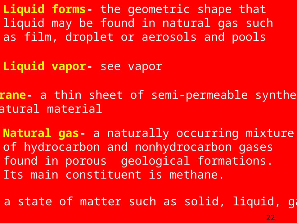
Natural gas- a naturally occurring mixture of hydrocarbon and nonhydrocarbon gases found in porous geological formations. Its main constituent is methane.
Phase- a state of matter such as solid, liquid, gas or vapor 22
Liquid vapor- see vapor
Membrane- a thin sheet of semi-permeable synthetic or natural material
Liquid forms- the geometric shape that liquid may be found in natural gas such as film, droplet or aerosols and pools
23
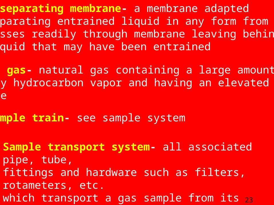
Rich gas- natural gas containing a large amount of heavy hydrocarbon vapor and having an elevated BTU value
Sample train- see sample system
Sample transport system- all associated pipe, tube, fittings and hardware such as filters, rotameters, etc. which transport a gas sample from its source to an intended destination such as an analyzer or sample cylinder
Phase-separating membrane- a membrane adapted for separating entrained liquid in any form from gases. Gas passes readily through membrane leaving behind any liquid that may have been entrained

Vapor-a substance, which is normally liquid at ambienttemperature and atmospheric pressure but becomes a gas at elevated temperature or lower pressures
Wet gas- a gas which contains a high concentration of water vapor
Volatility- The ease at which a liquid vaporizes.
24
Sample system- all components associated with extracting,transporting, and conditioning of a natural gas sample

Joule-Thomson effect
Reduction of pressure cools a gas due to a phenomenon known as the Joule-Thomson effect. The cooling effectmay lower the gas temperature below its dew point. When the temperature of a gas drops below its dew pointcondensation occurs. This in turn causes changes in thegas phase composition.
Restriction
High Pressure Lower Pressure
25

Demonstration of “Joule-Thomson effect”
Atmospheric Pressure
PROPANE VAPOR
125-150 PSI
Temperature of gas,after pressure drop,is slightly lowered bythe J.T. effect.
LIQUIDPROPANE
26

Demonstration of “Latent Heat of Vaporization”
AtmosphericPressure
27
PROPANE VAPOR
LIQUIDPROPANE
125 - 150 PSI
Temperature of gas,after liquid vaporizes,is substantially lower
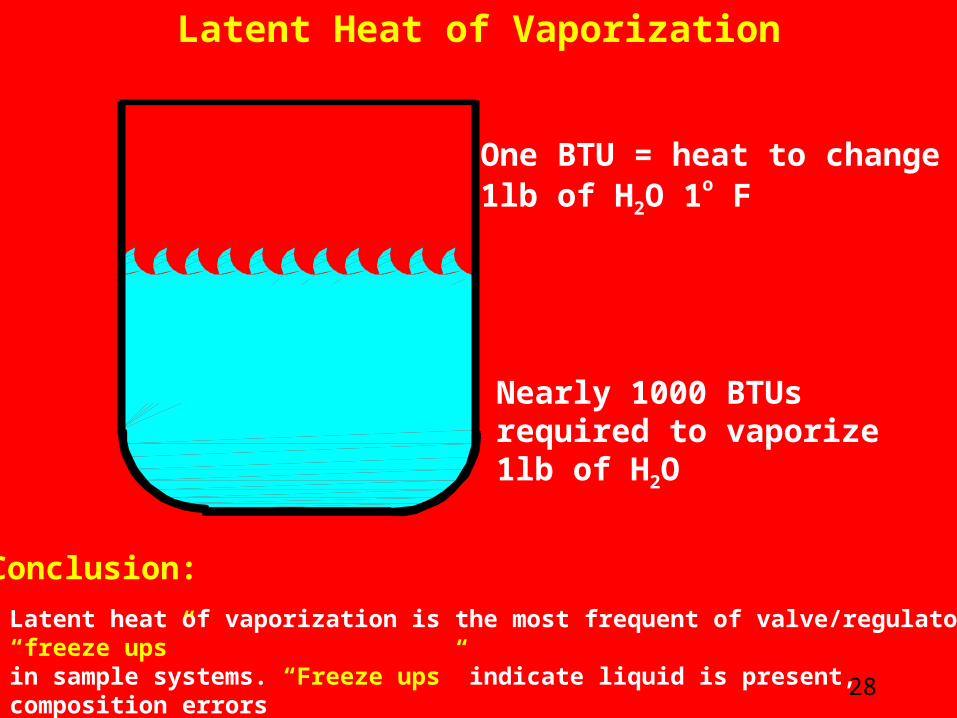
Nearly 1000 BTUs required to vaporize 1lb of H2O
One BTU = heat to change1lb of H2O 1o F
Latent Heat of Vaporization
Latent heat of vaporization is the most frequent of valve/regulator “freeze ups” in sample systems. “Freeze ups” indicate liquid is present, composition errors are likely to occur.
28
Conclusion:

A pure liquid and its vapor – No other gases presentA pure liquid and its vapor – No other gases present
•Equilibrium is a dynamic state of balance where the population of molecules per unit volume in the vapor space remains constant.
•The rate at which molecules pass from the liquid to the gas phase is dependent on the temperature
•Increasing the temperature increases the rate and conversely, lowering the temperature decreases the rate.
•The pressure caused by the gas phase molecules striking the containment vessel surface is the vapor pressure.
Liquid Phase
Gas/Vapor PhaseGas/Vapor Phase
Gas Molecules Leaving and Returning to the Liquid
29

A pure liquid and its vapor – Other gases presentA pure liquid and its vapor – Other gases present
•Number of vapor molecules in the Gas/Vapor Phase depends on the liquid’s vapor pressure.•Vapor pressure depends on temperature.•Concentration of vapor depends on system pressure.
Liquid Phase
Gas/Vapor Phase
Interface
30

Pressure and temperature changesin a gas containing a mixture of liquidsalter the gas phase composition
31
Gas / Vapor Phase
Liquid Phase
HC liquid #1
HC liquid #2
HC liquid #3

““Pressure Pressure Decreases”Decreases”
Pressure and temperature changesin a gas containing a mixture of liquidsalter the gas phase composition
32
Gas/VaporIncreases
Gas / Vapor Phase
Liquid Phase
HC liquid #1
HC liquid #2
HC liquid #3

Pressure and temperature changesin a gas containing a mixture of liquidsalter the gas phase composition
33
Gas / Vapor Phase
Liquid Phase
HC liquid #1
HC liquid #2
HC liquid #3

““Temperature Temperature Increases”Increases”
Pressure and temperature changesin a gas containing a mixture of liquidsalter the gas phase composition
34
Gas/VaporIncreases
Gas / Vapor Phase
Liquid Phase
HC liquid #1
HC liquid #2
HC liquid #3

Pressure and temperature changesin a gas containing a mixture of liquidsalter the gas phase composition
35
Gas / Vapor Phase
Liquid Phase
HC liquid #1
HC liquid #2
HC liquid #3

Pressure and temperature changesin a gas containing a mixture of liquidsalter the gas phase composition
36
Gas / Vapor Phase
Liquid Phase
HC liquid #1
HC liquid #2
HC liquid #3
““Pressure Pressure Increases”Increases”
Gas/VaporDecreases

Pressure and temperature changesin a gas containing a mixture of liquidsalter the gas phase composition
37
Gas / Vapor Phase
Liquid Phase
HC liquid #1
HC liquid #2
HC liquid #3
Pressure and temperature changesin a gas containing a mixture of liquidsalter the gas phase composition
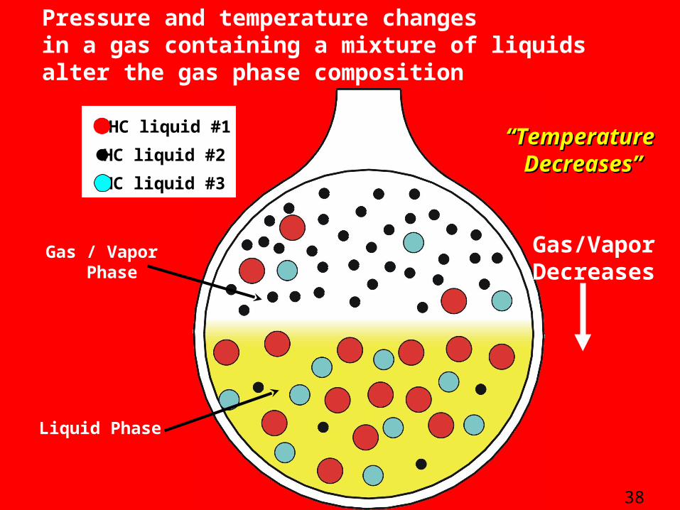
38
Gas / Vapor Phase
Liquid Phase
HC liquid #1
HC liquid #2
HC liquid #3
““Temperature Temperature Decreases”Decreases”
Gas/VaporDecreases

DesaturationDesaturation – Very important technique
A mixture of liquids, their vapor, and other gases presentA mixture of liquids, their vapor, and other gases present
Condensation
Evaporation
Liquid Phase
Saturated and at Dew point Temperature
•Saturated and at Dew point Temperature.•Lower temperature or increase pressure – condensation occurs.•Increase temperature or reduce pressure – will Desaturate.
39

What happens when liquid is carried over into the sample system and sample “pressure” is decreased?
External Pressure Regulator
Aerosol droplets
•Aerosol droplets enter probe•Pressure drop across regulator (or valve) causes liquids to flash (vaporize)•Gas phase composition changes•BTU value is altered•Flow rate calculations are impacted 40

What happens when liquid is carried over into the sample system and sample “pressure” is decreased?
Insertion Regulator
•Aerosol droplets enter probe•Pressure drop across regulator (or valve) causes liquids to flash (vaporize)•Gas phase composition changes•BTU value is altered•Flow rate calculations are impacted 41

Forms of Liquid Existing In A Pipeline
Film
Pool
Aerosol
Droplet
All Forms of Liquid Exhibit the Same Properties
42

Liquid in the pipeline is constantly changing forms
Aerosol generated from “wave” in surface film
Aerosols impinge on a surfaceand create large drops
High gas velocitywith liquid flowingacross a sharp object,such as an orifice plate,generates aerosols
Liquid Pools 43

Conclusion:
•Insertion (Probe) Regulators were designed to prevent condensation during pressure reduction.
•When liquid is entrained (present) in the sample source, they cause composition errors.
44

What happens when liquid is carried over into the sample system and sample “temperature” is increased?
Heat Tracing
•Aerosol droplets enter probe•Heat Tracing vaporizes the liquid •Gas phase composition changes•BTU value is altered•Flow rate calculations are impacted
45

Conclusion:
•Heat tracing is designed to prevent condensation.
•However, it will cause composition errorswhen liquid is entrained in the sample source
46

What happens when liquid is carried over into the sample system and sample “temperature” is decreased?
Ambient temperature is lower than the flowing gas temperature
•Aerosol droplets enter probe – this means that the gas phase is saturated•Cooling of the saturated gas phase results in “condensation” of some gas components•Condensation causes composition changes in the gas phase•BTU value is altered•Flow rate calculations are impacted 47

Conclusion
•Hardware designed to prevent condensation can change the sample gas composition when liquid is present
•When liquid is present in the source gas changes in either the temperature or pressure will change the gas phase composition, BTU value, and physical properties used in calculating flow rate.
48

-Small amount of liquid is equivalent to large volume gas
•Liquid has major impact on BTU
49

800 PSIG
Temp F 500 F 00 F -250 F -500 F -750 FMole%
N2 2.5 2.501 2.501 2.502 2.505
CO2 1.2 1.2 1.2 1.199 1.197
C1 93.75 93.769 93.786 93.808 93.847
C2 2 1.999 1.998 1.995 1.985
C3 0.352 0.351 0.35 0.347 0.339
iC4 0.042 0.042 0.041 0.041 0.038
nC4 0.064 0.064 0.063 0.06 0.055
iC5 0.014 0.014 0.013 0.012 0.01
nC5 0.026 0.025 0.024 0.021 0.016
C6 0.021 0.019 0.017 0.012 0.007
C7 0.015 0.01 0.005 0.002 0.001
C8 0.011 0.005 0.002 0.001 0
C9 0.005 0.001 0 0 0
Liquid g 0 0.0349 0.0691 0.122 0.247
100%Vapour1000 BTU Natural Gas 500 cc vessel
50Removal of 0.247g of liquid resulted in a loss of 3 BTU
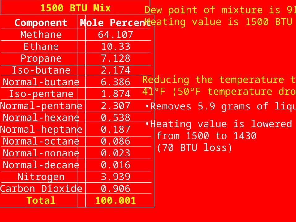
ComponentMethaneEthanePropane
Iso-butaneNormal-butane
Iso-pentaneNormal-pentaneNormal-hexaneNormal-heptaneNormal-octaneNormal-nonaneNormal-decane
NitrogenCarbon Dioxide
Total
Mole Percent64.10710.337.1282.1746.3861.8742.3070.5380.1870.0860.0230.0163.9390.906
100.001
1500 BTU Mix Dew point of mixture is 91ºFHeating value is 1500 BTU
Reducing the temperature to 41ºF (50ºF temperature drop)•Removes 5.9 grams of liquid
•Heating value is lowered from 1500 to 1430 (70 BTU loss)

No technology available for extracting a gas sample containing a representative amount of entrained liquid.
52
www.geniefilters.com

-Liquids entrained in Natural gas has caused many problems
-No distinction made between “entrained” and “condensed” liquid
•Impact often overlooked
*Analyzer damage is usually first concern
53
-Proper treatment depends on the origin of the liquid
www.geniefilters.com

-Entrained liquid not always easy to detect
•Erratic on-line gas analysis
•Spot, composite, on-line analyzer don’t agree
•Valve or Pressure Regulator freeze ups
54
Some indicators that liquid may be
present are:
www.geniefilters.com

Sources of Sampling Problems
•Entrained Liquid
•Condensed Liquid
•Construction Material for Sample Conditioning Components
•Contaminates
•Improper Selection of Sample Conditioning Components
•Ambient Temperature
•Cooling of Sample Gas Resulting From Pressure Drops
55

Sample Conditioning System Tasks
•Extraction
•Removal of Unwanted Liquids and Solids
•Pressure Regulation
•Transportation
•Preservation of Sample Composition
•Flow Control
•Stream Multiplexing and Cal Gas Switching56

Sample Conditioning System Tasks
ExtractionRemoval of Unwanted Liquids and SolidsPressure RegulationTransportationPreservation of Sample CompositionFlow ControlStream Multiplexing and Cal Gas Switching
Probe
Purpose – Exclusion of unwanted liquid and particles
Natural Gas Pipeline
57
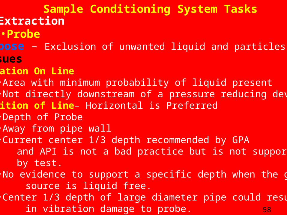
Sample Conditioning System TasksExtraction•ProbePurpose – Exclusion of unwanted liquid and particlesIssuesLocation On Line
•Area with minimum probability of liquid present•Not directly downstream of a pressure reducing device
Position of Line– Horizontal is Preferred•Depth of Probe•Away from pipe wall•Current center 1/3 depth recommended by GPA
and API is not a bad practice but is not supported by test.
•No evidence to support a specific depth when the gas source is liquid free.•Center 1/3 depth of large diameter pipe could result
in vibration damage to probe. 58

Sample Conditioning System Tasks
Extraction
Purpose – Exclusion of unwanted liquid and particles
•Probe
Issues – ContinuedOpening
•Square Cut – Probably best for all applications•Angle Cut – Not necessary and if installed incorrectly
could increase liquid intake. Types of Probes
•Straight Probe•Pitot Tube•Probe with Integral Regulator•Probe with Membrane Liquid Separator
and Integral Regulator59

Extraction
Purpose – Exclusion of unwanted liquid and particles
•Probe
Issues – ContinuedTypes of Probes
•Straight Probe
Positive – Helps prevent wall film from entering sample system
Negative – Does not prevent entrained aerosols from entering sample systems. Aerosols arealmost always present whenever liquidis present in any form.
60

61
Straight Probe

Positive – Helps prevent wall film from entering sample system
Provides external circulation of sample gasNegative – Does not prevent entrained aerosols from
entering sample systems. Aerosols arealmost always present whenever liquidis present in any form. 62
Extraction
Purpose – Exclusion of unwanted liquid and particles
•Probe
Issues – ContinuedTypes of Probes
•Pitot Tube

63
FLOW
TO ANALYZER OR COMPOSITE SAMPLER
½“ NPT, ¾” NPT or 1” NPT
¼“ NPT Full OpeningS.S. Plug Valve(Optional)
ProductReturn
Product Out
CLof Pipeline
Low Pressure Return
Pitot Tube

Insertion Regulator
•Aerosol droplets enter probe•Pressure drop across regulator (or valve) causes liquids to flash (vaporize)•Gas phase composition changes•BTU value is altered•Flow rate calculations are impacted
64
•Probe with Integral RegulatorTypes of Probes
Negative
Positive•Helps prevent condensation due to Joule-Thomson Cooling

AdvantagesAdvantages-Liquid is removed before pressure reduction
-Vapor phase composition changes are avoided
Types of ProbesTypes of ProbesProbe with Integral
Membrane & Regulator
65

Membrane
Foot Valve
GasFlow
CoalescedLiquid
GenieProbe
Regulator
66

Genie ModelGenie Model130 HPM130 HPM
67
External means for removing liquidfrom Sample Gas at line pressure
Gas & Entrained Liquid
Gas Only
Entrained Liquid (shed by the membrane) is
returned to the sample source.

Handling LiquidsHandling Liquids-Remove at line pressure & temperature conditions.
-Prevents changes in gas composition
-Prevent condensation-Heat and/or insulate
-Lower pressure at source to lower Dew point
-Protect analyzer-Provide liquid “safety net” at analyzer68
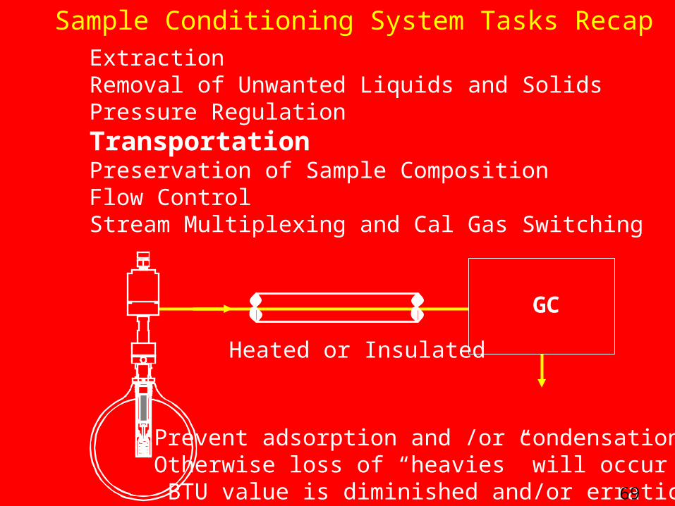
Sample Conditioning System Tasks RecapExtractionRemoval of Unwanted Liquids and SolidsPressure RegulationTransportationPreservation of Sample CompositionFlow ControlStream Multiplexing and Cal Gas Switching
Prevent adsorption and /or condensationOtherwise loss of “heavies” will occur and BTU value is diminished and/or erratic
GC
Heated or Insulated
69

Transporting Sample LinesTransporting Sample Lines
-Diameter-Diameter-Length
-Slope
-Heating/Insulation
-Temperature Differences
DiameterDiameter1/8” diameter for lines under 25’ long¼”diameter for lines longer than 25’
70

-Diameter
-Length-Length-Slope
-Heating/Insulation
-Temperature Differences
LengthLength
Minimize length–reduce pressure drop–reduce lag time
–reduce exposed surface area
Transporting Sample LinesTransporting Sample Lines
71

-Diameter
-Length
-Slope-Slope
-Heating/Insulation
-Temperature Differences
SlopeSlopeTo Prevent accumulation of liquid pools
Transporting Sample LinesTransporting Sample Lines
72

-Diameter
-Length
-Slope
-Heating/Insulation-Heating/Insulation-Temperature Differences
-Prevent sample gas from approaching dew point.
Heating/InsulationHeating/Insulation
-Prevent condensation.
Transporting Sample LinesTransporting Sample Lines
73

Heat TracingHeat Tracing
•Heat trace when ambient conditions could cause sample wetted components temperature to fall within 25°F of the expected hydrocarbon dew point.
•Heat trace all exposed components.
•When electrical heat tracing is used make sure that:
(a) The heat tracing tape meets electrical codes for the intended service
(b) The heat tracing tape is self-limiting to prevent over-heating (over-heated electrical components could cause injury or an explosion)
•A catalytic heater can be used for some applications.
•Insulate all heat traced components to prevent heat loss.74
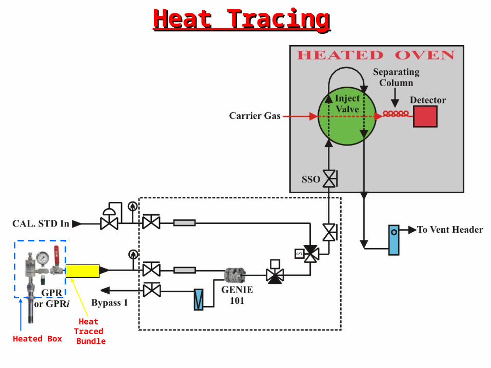
Heated Box
Heat Traced Bundle
Heat TracingHeat Tracing

-Diameter
-Length
-Slope
-Heating/Insulation
-Temperature Differences-Temperature Differences
-Do not allow sample to cool below the the liquid removal temp. (Dew point)
-Temperature Differences-Temperature Differences
-Ambient and analyzer house temp. conditions reversed between winter/ summer
Transporting Sample LinesTransporting Sample Lines
76

““Lag Time”/Flow rateLag Time”/Flow rate
-Too much emphasis given to “Lag Time”
-Excessive bypass is not cheap
-Balance sample conditioning needs with “Lag Time” requirements
77

ExtractionRemoval of Unwanted Liquids and SolidsPressure RegulationTransportationPreservation of Sample CompositionFlow ControlStream Multiplexing and Cal Gas Switching
Sample Conditioning System Tasks Recap
•Remove unwanted components without changing gas composition.
•Prevent condensation or adsorption phase of components.
78

Diagram for a Typical Single Stream Gas ChromatographInstallation with GPR and Genie Model 101

Purpose of Genie Probe Regulator (GPR) is to precondition the gas sample by:
-removal of liquid (if present) at pipeline conditions of pressure and temperature.
-pressure regulation (after liquid removal)
-compensation for Joule-Thomson cooling effect during pressure regulation
-removal of all solid particles
Benefit:Prevent sample composition changes.
80

Purpose of a Genie Model 101 is to provide a safety net for the Gas Chromatograph by:
-removal of all liquid or solid particles which may be present due to unusual conditions or equipment failure.
Benefit:
Protecting the Gas Chromatograph reduces maintenance expenditures and increases reliability.
81
Surface AdsorptionSurface Adsorption
Surfaces attract gas molecules-high affinity for some molecules
For a given surface/gas composition-increased temperature/decreased pressure
decreases adsorption-decreased temperature/increased pressure
increases adsorption-heating sample wetted surfaces
minimizes surface adsorption-concentration in gas phase
impacts adsorption 82

Surface AdsorptionSurface Adsorption
Surface adsorption is undesirable-stores molecules in sample system
-temperature/pressure sensitivity
-night/day temperature cycles causes composition changes in sample gas
83
-maintain sample wetted surfaces at least 25º F above the sample dew point

Calibration gas issueCalibration gas issue
Dew point-know what the calibration gas Dew point is.
-maintain the temperature at least 25º F above the dew point at all times when calibration gas is in service.
-removing gas when below Dew point will distort the calibration gas composition
84

Composition
Storage-stratification does not occur
-heat or insulate to prevent temperature differences in cylinder. (Recommend heating at least 25°(Recommend heating at least 25°F F above theabove the calibration gas Dew point, but not exceeding 140°calibration gas Dew point, but not exceeding 140°F). F).
Calibration gas issueCalibration gas issue
-place cylinder on an insulating medium to prevent a cold floor contacting cylinder bottom
-look for increases of the heavy molecules as the cylinder pressure lowers. 85

G.C.G.C.
Liquefied Petroleum Gas (LPG) Analyzers Liquefied Petroleum Gas (LPG) Analyzers
Genie Model205 HP
LPG &Immiscible
Liquids
(VPC)Vaporizing
PressureRegulator
LGP Vapor
GenieModel
101
Bypass
LPG & AllImmiscible
Liquids
Vent

Referenced PublicationsReferenced Publications
API Chapter 14.1 “Collecting and Handling of Natural Gas Sample for
Custody Transfer”Topical Report – Prepared by K.A. Behring II
Of Southwest Research Institute
Technical Memorandum – GPRi report number GPRi - 98/0034
Prepared by K.A. Behring IIHandbook of Chemistry and Physics
Published by Chemical Rubber Publishing Co.40th Edition
Perry’s Chemical Engineering Handbook 6th Edition
Mark’s Standard Handbook for Mechanical Engineers 6th Edition
87
