training handbook - carborep
TRANSCRIPT
IO3: ECBRT CURRICULUM ADAPTATION AND DEVELOPMENT OF TRAINING
MATERIALS
1
TRAINING HANDBOOK
This project has been funded with support from the European Commission. This publication reflects
the views only of the author, and the Commission cannot be held responsible for any use which may
be made of the information contained therein.
08/08/2019
www.carborep.eu
IO3: ECBRT CURRICULUM ADAPTATION AND DEVELOPMENT OF TRAINING
MATERIALS
2
CARBOREP
European Harmonized Training for Personnel
working with Car Body Repair Technology
2016-1-UK01-KA202-024374
IO3: ECBRT CURRICULUM ADAPTATION AND DEVELOPMENT
OF TRAINING MATERIALS
IO3: ECBRT CURRICULUM ADAPTATION AND DEVELOPMENT OF TRAINING
MATERIALS
3
Index
foreword ..................................................................................................................................................... 5
Competence Unit 1 ................................................................................................................................. 6
1. Steel Structural Body Construction – Welding Repair ...................................................... 6
1.1 Materials Used In The Manufacture Of Vehicle Bodies ........................................ 6
1.2 MAG Welding And GMAW Brazing ....................................................................... 17
1.2.1 MAG Welding And GMAW Brazing Overview ..................................................... 18
1.2.2 MAG Welding And GMAW’s Processes ................................................................. 39
1.2.3 Specifications Of Gas Metal Arc Weld Brazing .................................................... 40
1.2.4 Characteristics Of Gas Metal Arc Weld Brazing And MAG Welding............ 41
1.2.5 Braze Welding Preparation In Car Body Repair .................................................. 42
1.2.6 MAG And GMAW Technical Application In Car Body Repair ......................... 43
1.2.7 Health And Safety, And Environmental Safety .................................................... 55
1st Practical Training ....................................................................................................... 70
1.3 Resistance Spot Weld Joining Technology ........................................................... 76
1.3.1 The Resistance Spot Welding Process .................................................................... 76
1.3.2 Resistance Spot Welding Technical Overview ..................................................... 79
1.3.3 Health And Safety, And Environmental Safety ................................................. 104
2nd Practical Training .................................................................................................... 114
Competence Unit 2 ............................................................................................................................ 119
Steel/Aluminium/Multimaterial Structural Body Construction – Adhesive Bonding
And Mechanical Fasteners Repairs .......................................................................................... 119
2.1 Materials Used In The Manufacture Of Vehicle Bodies .................................... 119
2.2 Adhesive Bonding In Car Body Repair ................................................................ 123
2.2.1 Types Of Adhesives .................................................................................................... 124
2.2.2 Applications Of Adhesive Bonding ....................................................................... 127
2.2.3 The Characteristics Of Adhesives .......................................................................... 130
2.2.4 Comparison With Other Joining Methods ......................................................... 133
IO3: ECBRT CURRICULUM ADAPTATION AND DEVELOPMENT OF TRAINING
MATERIALS
4
2.2.5 Adhesives Technical Application In Car Body Repair ..................................... 134
2.2.6 Adhesive Product Data And Safety Sheets ........................................................ 154
2.3 Mechanical Fasteners In Car Body Repair ........................................................... 159
3rd Practical Training ................................................................................................... 171
2.4 Hybrid Joining In Adhesive Bonding ........................ Error! Bookmark not defined.
2.4.1. Adhesive Bonding And Resistance Spot Welding .......................................... 176
2.4.3 Quality Control ............................................................................................................. 179
2.4.4 Health And Safety, And Environmental Safety ................................................. 185
4th Practical Training .................................................................................................... 187
5th Practical Training .................................................................................................... 191
6th Practical Training .................................................................................................... 195
7th Practical Training .................................................................................................... 197
8th Practical Training .................................................................................................... 199
9th Practical Training .................................................................................................... 202
10th Practical Training ..................................................................................................... 207

IO3: ECBRT CURRICULUM ADAPTATION AND DEVELOPMENT OF TRAINING
MATERIALS
5
Foreword
The present document is the European Car Body Repair Technician Handbook.
This handbook comprises two Competence Units: Competence Unit 1 “Steel Structural
Body Construction – Welding Repair”; and Competence Unit 2
“Steel/Aluminium/Multimaterial Structural Body Construction – Adhesive Bonding and
Mechanical Fasteners Repairs”.
The CARBOREP handbook has been produced under the scope of the CARBOREP
project (CARBOREP - European Harmonized Training for Personnel working with Car
Body Repair Technology, Project Reference number: 2016-1-UK01-KA202-024374),
funded with support from the European Commission. This publication reflects the
views only of the author, and the Commission cannot be held responsible for any use
which may be made of the information contained therein.
Copies of this document are available at CARBOREP website www.carborep.eu.
IO3: ECBRT CURRICULUM ADAPTATION AND DEVELOPMENT OF TRAINING
MATERIALS
6
Competence Unit 1
1. Steel Structural Body Construction – Welding
Repair
1.1 MATERIALS USED IN THE MANUFACTURE OF VEHICLE
BODIES
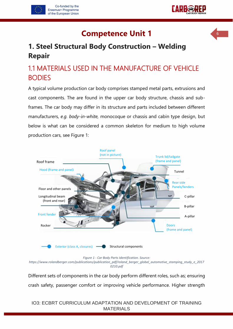
A typical volume production car body comprises stamped metal parts, extrusions and
cast components. The are found in the upper car body structure, chassis and sub-
frames. The car body may differ in its structure and parts included between different
manufacturers, e.g. body-in-white, monocoque or chassis and cabin type design, but
below is what can be considered a common skeleton for medium to high volume
production cars, see Figure 1:
Figure 1 - Car Body Parts Identification. Source: https://www.rolandberger.com/publications/publication_pdf/roland_berger_global_automotive_stamping_study_e_2017
0210.pdf
Different sets of components in the car body perform different roles, such as; ensuring
crash safety, passenger comfort or improving vehicle performance. Higher strength
Roof frame
Floor and other panels
Longitudinal beam (front and rear)
Rocker
Tunnel
C-pillar
B-pillar
A-pillar
Doors (frame and panel)
Front fender
der
Doors (frame and panel)
Roof panel (not in picture)
Trunk lid/tailgate (frame and panel)
Rear side Panels/fenders
Hood (frame and panel)
Exterior (class A, closures) Structural components

IO3: ECBRT CURRICULUM ADAPTATION AND DEVELOPMENT OF TRAINING
MATERIALS
7
materials have limited formability and are usually used in non-visible areas where a
high level of structural integrity is required, for instance in high load zones. While lower
strength more formable materials are usually used for visible panels that require
complex shapes and high-quality surface finishes (e.g. door panels) or for bolt on crash
crumple zones where their energy absorption capability is paramount (e.g. inner
reinforcement’ bumpers). Regardless of the materials used, the distribution of different
strength materials throughout the car body is employed to, primarily, minimize cost
and weight while complying with mechanical properties design requirements.
Despite the trend over the past few decades towards the use of different materials in
car body elements, especially aluminium, most production cars mainly have steel parts.
Aluminium’s use, despite being more expensive, is due to its reduced mass density,
which in many cases, maintains the required mechanical properties. Other cars,
typically high-end vehicles, use exotic materials such as carbon fibre and trends in
magnesium use are also starting to begin.
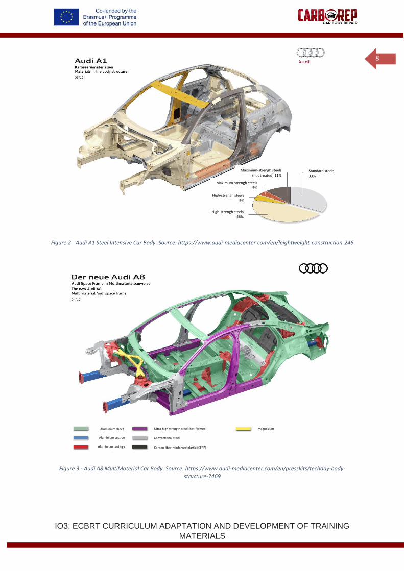
Often within the same manufacturer, different models have different predominant
materials in the car body, exemplified by Audi and their A1, A8, and R8 Coupé, shown
in Figures 2, 3 and 4. Without prior knowledge of the vehicle, it is not possible to state
definitely what the material a given part is made of. Visual inspection may enable
identification of the material; however, it should be complemented with data sheet
analysis, to find, for instance, the specific steel family and its corresponding properties,
treatment and coatings.
IO3: ECBRT CURRICULUM ADAPTATION AND DEVELOPMENT OF TRAINING
MATERIALS
8
Figure 2 - Audi A1 Steel Intensive Car Body. Source: https://www.audi-mediacenter.com/en/leightweight-construction-246
Figure 3 - Audi A8 MultiMaterial Car Body. Source: https://www.audi-mediacenter.com/en/presskits/techday-body-structure-7469
Standard steels 33%
Maximum-strengh steels (hot treated) 11%
Maximum-strengh steels 5%
High-strengh steels 5%
High-strengh steels 46%
Aluminium sheet
Aluminium section
Aluminium castings
Ultra-high strength steel (hot-formed)
Conventional steel
Carbon fiber-reinforced plastic (CFRP)
Magnesium
IO3: ECBRT CURRICULUM ADAPTATION AND DEVELOPMENT OF TRAINING
MATERIALS
9
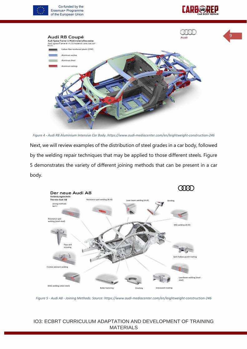
Figure 4 - Audi R8 Aluminium Intensive Car Body. https://www.audi-mediacenter.com/en/leightweight-construction-246
Next, we will review examples of the distribution of steel grades in a car body, followed
by the welding repair techniques that may be applied to those different steels. Figure
5 demonstrates the variety of different joining methods that can be present in a car
body.
Figure 5 - Audi A8 - Joining Methods. Source: https://www.audi-mediacenter.com/en/leightweight-construction-246
Laser beam welding (Al-Al)
Joining methods 04/17
Resistance spot welding (steel-steel)
Flow-drill screwing
Resistance spot welding (Al-Al) Bonding
MIG welding (Al-Al)
Semi-hollow punch-riveting
Laserbeam welding (steel-steel)
Grip punch-riveting Clinching Roller hemming MAG welding (steel-steel)
Carbon fiber-reinforced plastic (CFRP)
Aluminum section
Aluminum sheet
Aluminum castings
Friction-element welding
IO3: ECBRT CURRICULUM ADAPTATION AND DEVELOPMENT OF TRAINING
MATERIALS
10
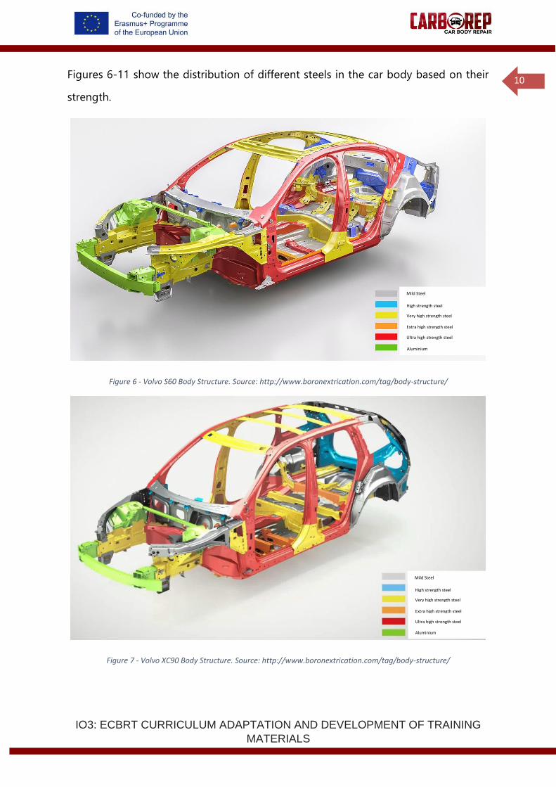
Figures 6-11 show the distribution of different steels in the car body based on their
strength.
Figure 6 - Volvo S60 Body Structure. Source: http://www.boronextrication.com/tag/body-structure/
Figure 7 - Volvo XC90 Body Structure. Source: http://www.boronextrication.com/tag/body-structure/
Mild Steel
High strength steel
Very high strength steel
Extra high strength steel
Ultra high strength steel
Aluminium
Mild Steel
High strength steel
Very high strength steel
Extra high strength steel
Ultra high strength steel
Aluminium
IO3: ECBRT CURRICULUM ADAPTATION AND DEVELOPMENT OF TRAINING
MATERIALS
11
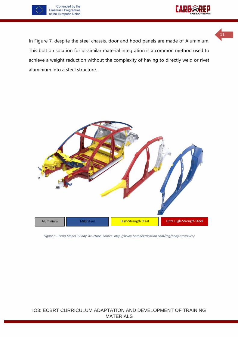
In Figure 7, despite the steel chassis, door and hood panels are made of Aluminium.
This bolt on solution for dissimilar material integration is a common method used to
achieve a weight reduction without the complexity of having to directly weld or rivet
aluminium into a steel structure.
Figure 8 - Tesla Model 3 Body Structure. Source: http://www.boronextrication.com/tag/body-structure/
Aluminium Mild Steel High-Strength Steel Ultra High-Strength Steel
IO3: ECBRT CURRICULUM ADAPTATION AND DEVELOPMENT OF TRAINING
MATERIALS
12
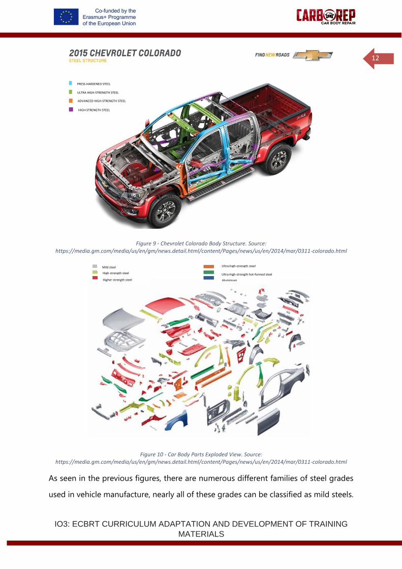
Figure 9 - Chevrolet Colorado Body Structure. Source: https://media.gm.com/media/us/en/gm/news.detail.html/content/Pages/news/us/en/2014/mar/0311-colorado.html
Figure 10 - Car Body Parts Exploded View. Source: https://media.gm.com/media/us/en/gm/news.detail.html/content/Pages/news/us/en/2014/mar/0311-colorado.html
As seen in the previous figures, there are numerous different families of steel grades
used in vehicle manufacture, nearly all of these grades can be classified as mild steels.
PRESS HARDENED STEEL
ULTRA HIGH-STRENGTH STEEL
ADVANCED HIGH-STRENGTH STEEL
Ultra-high-strength steel
HIGH-STRENGTH STEEL
High-strength steel
Aluminium
Ultra-high-strength hot-formed steel
Higher-strength steel
Mild steel
IO3: ECBRT CURRICULUM ADAPTATION AND DEVELOPMENT OF TRAINING
MATERIALS
13
However, the properties of the individual grades can vary dramatically, as can the
welding and joining performance. The definitions and names of each grade are based
around either; the microstructure, the mechanical properties or the production
processes used for the specific material. Individual car companies often have their own
preferred terms and codes for material grades, which further complicates material
identification. However, it is possible to group the steel grades into families where the
grades have similar properties. Within a specific family mechanical properties (ultimate
tensile strength, yield, elongation etc. will fall into a range of values). The materials
within a specific family can be handled in a similar way when it comes to
manufacturing, or more specifically joining in vehicle body repair.
For the purpose of this document four steel grade families will be referred to:
• Drawing, deep drawing and high formability steels: These steels have fully
ferritic microstructures and usually have very low carbon contents. These
materials are designed for very high fomability and often have a high surface
quality making them suitable for outer panels or highly formed interior
components. The steels typically offer few challenges for welding and can be
joined by all common processes.
• High-Strength Steel (HSS): Have mainly ferritic microstructures, but in order
to achieve enhanced mechanical properties (ultimate tensile strengths from 350
– 550MPa) a fine grain size is required. Specific alloying additions are employed
to refine grains and strengthen the microstructure but still retain good
formability. Importantly for welding, carbon contents remain low in these
materials. Within this family common material grades include high strength low
alloy steels (HSLA), Carbon Manganese steels (CMn) and some higher strength
bake hardening and rephosphorised grades. These materials are typically easy
to weld and present few problems in vehicle manufacture. All three welding
processes can be used in vehicle repair.
IO3: ECBRT CURRICULUM ADAPTATION AND DEVELOPMENT OF TRAINING
MATERIALS
14
• Advanced-High-Strength Steel (AHSS): is a generic group of metals with
ultimate tensile strength greater than 550 MPa. The microstructures of these
materials can be a mixture of ferrite, austenite, martensite and bainite. Specific
chemical compositions and multiphase microstructures resulting from
combinations of heat treatments and other strengthening mechanisms means
a range of strength, ductility and toughness may be achieved. This steel family
includes steels such as Dual Phase (DP), Complex-Phase (CP), Ferritic-Bainitic
(FB), Transformation-Induced Plasticity (TRIP), and Twinning-Induced Plasticity
(TWIP). For instance, DP steels are commonly used in the crash zone given their
high-energy absorption capability. Some AHSS may require specific welding
parameters (e.g. TRIP or TWIP), but in general this family of materials can still
be welded without particular difficulty. AHSS is very commonly be welded to
other AHSS and even mild steels by means of Resistance Spot Welding (in many
modern vehicles more than 50% of the welds contain one or more AHSS
material). All three welding processes can be used to repair these materials but
caution should be taken to reduce potential distortion resulting from the high
heat input of the welding. Also, high hardness phases can result from welding,
which may reduce the fracture toughness of welds.
• Ultra-High-Strength Steel (UHSS): characterized by having tensile strength of
at least 780 MPa. UHSS grades have a predominantly martensitic
microstructure, small proportions of other phases may be present. UHSS
includes Dual Phase (DP), Complex-Phase (CP), Induced Plasticity (TRIP), Hot-
Formed (HF) also known as press hardened steels (PHS), Martensitic (MS or
MART). UHSS has similar welding properties to AHSS but with higher strength
(and a resulting lower ductility). An example of UHSS use is MS steels are used
as structural elements such as B pillars for their extremely high-strength
characteristic. In principal these materials are all still weldable, but the effect of
IO3: ECBRT CURRICULUM ADAPTATION AND DEVELOPMENT OF TRAINING
MATERIALS
15
heat the properties of the weld and surrounding heat affected zone can in some
cases severely deteriorate the integrity of a joint. For these materials thorough
knowledge of the specific steel should be acquired to decide which welding
procedures to execute.
It is important to introduce steel coatings used in the automotive industry, since they
influence whether a given joining method may or may not be applied, and in which
conditions. Coatings are mainly used to alter a surface’s properties, such as adhesion,
wettability, colour and texture, and corrosion or wear resistance. In the automotive
industry, steel coatings primarily aim to enhance corrosion resistance.
Many metallic coatings include zinc, either in a pure zinc coating or in a zinc alloy
coating. Zinc works as a sacrificial anode for protecting the steel against corrosion,
given its anodic potential dissolution when compared to iron.
• Electrogalvanizing: coating is bonded to the surface by running current
through a solution of a zinc anode and a steel conductor.
• Hot-dip Galvanization: creates a metallurgical bond between the base metal
and the coating by immersing the steel part in molten zinc. When exposed to
the atmosphere, pure zinc reacts with oxygen, creating a chain reaction that
results in zinc carbonate (ZnCO3).
• Galvanneal Coating: a combination of a hot-dip galvanization and an
annealing process that results in the formation a zinc-iron alloy. This alloy is
created due to the heat exchange in the annealing furnace which promotes
diffusion between the iron and zinc layers.
• Aluminized Steel: creates a metallurgical bond between the base metal and
the aluminium-silicon alloy in a hot-dip process. Widely used in exhaust
systems.
IO3: ECBRT CURRICULUM ADAPTATION AND DEVELOPMENT OF TRAINING
MATERIALS
16
When welding galvanized steel, one must be aware of the problems that arise from
the volatilization of zinc in the coating, e.g. spatter, porosity, fumes, and potential weld
cracking.
When short-circuiting or spray metal transfer is used as the joining method, the
volatilized zinc rising from the plate surface causes the arc to become unstable and
generate considerable spatter. Moreover, zinc vapor can be trapped in the solidifying
weld puddle, causing porosity.
Unlike a galvanized coating, an aluminium coating is not volatile, but it does produce
a high-melting-point oxide. This oxide may interfere with arc stability, cause spatter,
and prevent good surface wetting which in turn creates poor bead shape.
In current welding methods, zinc is often removed from the joint surfaces before the
weld or the joint is gapped to allow vapor to escape. Gas Metal Arc Welding
performance can be enhanced by carefully choosing the wire size and type.
Compared to steels, aluminium alloys are specially regarded as a lightweight
alternative. Other advantages include its good durability and corrosion resistance. On
the other hand, its weldability is still an issue and great care must be taken when
choosing welding parameters, tool geometry, thermal cycles during welding and post-
weld heat treatment, so that the desired microstructure and strength may be achieved.
Nevertheless, the use of joining techniques that do not resort to heat, e.g. mechanical
joining and adhesive bonding, enables the growth of aluminium parts used in the
automotive industry.
Aluminium is often joined by combining mechanical joints, such as self-piercing rivets,
with adhesive bonding, which often meets the mechanical properties’ requirements in
many areas of the car body. Recent technology advancements enable the use of many
welding techniques, namely Resistance Spot Welding and Arc Welding.
IO3: ECBRT CURRICULUM ADAPTATION AND DEVELOPMENT OF TRAINING
MATERIALS
17
Similarly to steel grades, different Aluminium alloys have disparate inherent
mechanical properties and, therefore, vehicle applications. Here, three Aluminium
alloys will be referred to, given the fact that these are the most frequently used in the
automotive industry.
• 5000 Al-Mg: characterized by having great strength-to-weight ratio and
formability properties. Common applications include the use of: 5182 in interior
body panels given its good formability and stress corrosion cracking
performance; and 5022, with higher strength and formability, in bonnets, roofs,
doors and fenders.
• 6000 Al-Mg-Si: by far the most common Aluminium alloy used in the
automotive industry, given its higher strength when compared to the previous
alloy. It is heat-treatable, highly formable and reasonably well weldable. For
instance, 6063 is used in seat frames and roof railings.
• 7000 Al-Zn-Mg: target of recent developments to achieve greater strength-
alloys. Besides its greater cost, it has the downside of having poorer corrosion
properties, which may be an issue when welded. 7003 and 7046 alloys may be
used in bumper reinforcements and impact beams.
1.2 MAG WELDING AND GMAW BRAZING
Weld brazing is the joining of metals with a process similar to fusion welding using a
filler metal with a lower melting point than the parent metal and without intentionally
melting the parent metal.
Metal Active Gas (MAG) welding (EN ISO 4063 process 135) and Gas Metal Arc Weld
(GMAW) Brazing (EN ISO 4063 process 973) can be applied to repair the damaged
body of an automobile.
IO3: ECBRT CURRICULUM ADAPTATION AND DEVELOPMENT OF TRAINING
MATERIALS
18
1.2.1 MAG Welding and GMAW Brazing Overview
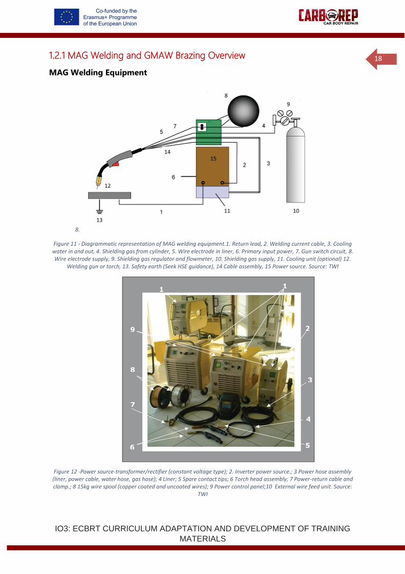
MAG Welding Equipment
8.
Figure 11 - Diagrammatic representation of MAG welding equipment.1. Return lead, 2. Welding current cable, 3. Cooling water in and out, 4. Shielding gas from cylinder, 5. Wire electrode in liner, 6. Primary input power, 7. Gun switch circuit, 8. Wire electrode supply, 9. Shielding gas regulator and flowmeter, 10. Shielding gas supply, 11. Cooling unit (optional) 12.
Welding gun or torch, 13. Safety earth (Seek HSE guidance), 14 Cable assembly, 15 Power source. Source: TWI
Figure 12 -Power source-transformer/rectifier (constant voltage type); 2. Inverter power source.; 3 Power hose assembly (liner, power cable, water hose, gas hose); 4 Liner; 5 Spare contact tips; 6 Torch head assembly; 7 Power-return cable and clamp.; 8 15kg wire spool (copper coated and uncoated wires); 9 Power control panel;10 External wire feed unit. Source:
TWI
10
1
9 2
8
3
7
4
6 5
IO3: ECBRT CURRICULUM ADAPTATION AND DEVELOPMENT OF TRAINING
MATERIALS
19
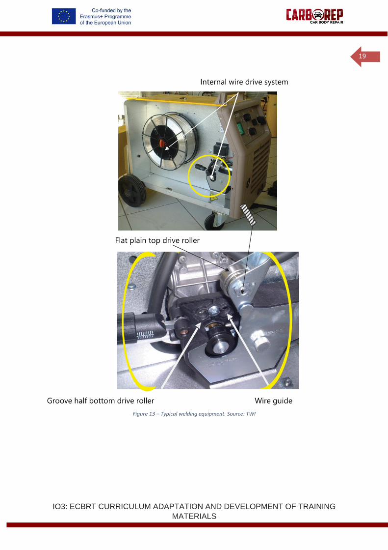
Groove half bottom drive roller Wire guide
Figure 13 – Typical welding equipment. Source: TWI
Flat plain top drive roller
Internal wire drive system
IO3: ECBRT CURRICULUM ADAPTATION AND DEVELOPMENT OF TRAINING
MATERIALS
20
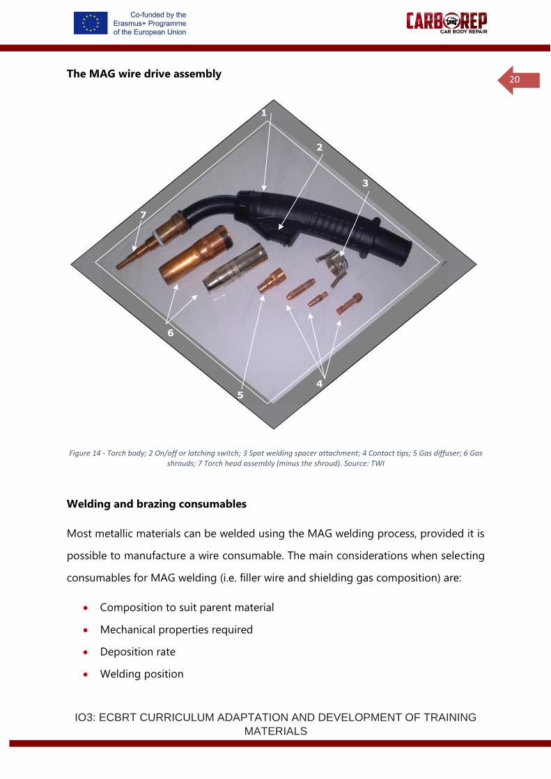
The MAG wire drive assembly
Figure 14 - Torch body; 2 On/off or latching switch; 3 Spot welding spacer attachment; 4 Contact tips; 5 Gas diffuser; 6 Gas shrouds; 7 Torch head assembly (minus the shroud). Source: TWI
Welding and brazing consumables
Most metallic materials can be welded using the MAG welding process, provided it is
possible to manufacture a wire consumable. The main considerations when selecting
consumables for MAG welding (i.e. filler wire and shielding gas composition) are:
• Composition to suit parent material
• Mechanical properties required
• Deposition rate
• Welding position
1
2
3
7
6
4
5
IO3: ECBRT CURRICULUM ADAPTATION AND DEVELOPMENT OF TRAINING
MATERIALS
21
• Bead appearance and penetration profile
• Quality issues, e.g. wire feedability
• Cost issues
Both wire and shielding gas composition are essential variables in MAG
welding/brazing and will, therefore, influence the process performance.
Wire electrode selection
Key characteristics:
• Wires are available in a wide range of compositions to suit different metallic
materials, e.g. ferritic steels, austenitic stainless steels, aluminium alloys, nickel
alloys, titanium alloys
• MAG wires are normally specified by composition
• Wires are typically supplied with diameters in the range 0.8mm to 2.4mm
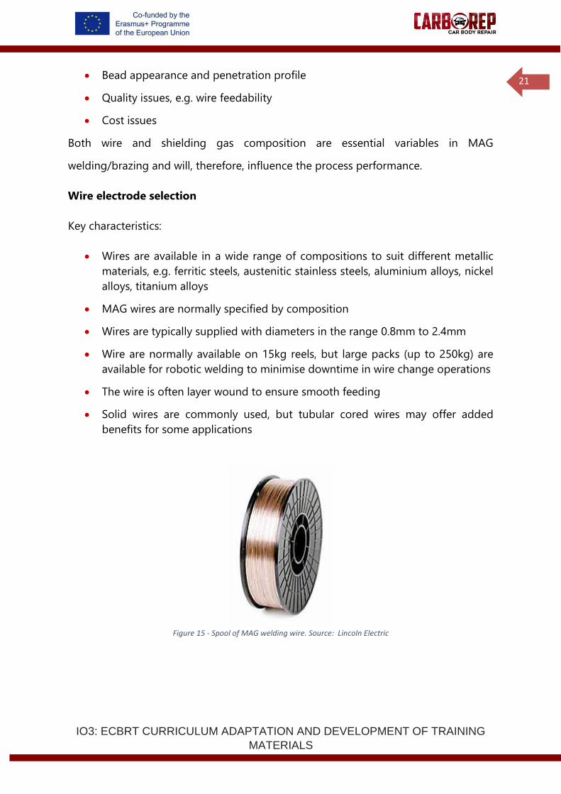
• Wire are normally available on 15kg reels, but large packs (up to 250kg) are
available for robotic welding to minimise downtime in wire change operations
• The wire is often layer wound to ensure smooth feeding
• Solid wires are commonly used, but tubular cored wires may offer added
benefits for some applications
Figure 15 - Spool of MAG welding wire. Source: Lincoln Electric
IO3: ECBRT CURRICULUM ADAPTATION AND DEVELOPMENT OF TRAINING
MATERIALS
22
Wire composition
Selection of the appropriate composition of the wire electrode can be a difficult task.
For most applications, wires are designed to give weld metals with matching
composition to the base material. In practice, this means that wire compositions tend
to be slightly over-alloyed to compensate for the burn-off of alloying elements in the
arc. The composition can also be modified for operation under a particular shielding
gas mixture, particularly for metal-cored and flux-cored wires.
The selection of consumables should be confirmed by welding trials and procedure
qualification testing in accordance with the applicable application Code or Standards.
The main sources of information are:
• Electrode manufacturer's handbook
• Electrode manufacturer's technical department
• Parent material manufacturer
• Previous experience or procedures
• Experts in your EWF member society (www.ewf.be)
Carbon and low alloy steels
Solid wires for welding steels with active shielding gases are deoxidised with
manganese and silicon to avoid porosity. There may also be titanium and aluminium
additions. Mild steel filler wires are available with different levels of deoxidants, known
as double or triple de-oxidised wires. More highly deoxidised wires are more expensive
but are more tolerant of the plate surface condition, e.g. mill scale, surface rust, oil,
paint and dust. There may, therefore, be a reduction in the amount of cleaning of the
steel before welding.
These deoxidiser additions yield a small amount of 'glassy' slag on the surface of the
weld deposit, commonly referred to as silica deposits. These small pockets of slag are
easily removed with light brushing; but when galvanising or painting after welding, it
IO3: ECBRT CURRICULUM ADAPTATION AND DEVELOPMENT OF TRAINING
MATERIALS
23
is necessary to use shot blasting. During welding, it is common practice to weld over
these small islands since they do not represent a thick slag, and they usually spall off
during the contraction of the weld bead. However, when multipass welding, the slag
level may build up to an unacceptable level causing weld defects and unreliable arc
starting.
Steel wires usually have a flash coating of copper to improve current pick-up and to
extend the shelf life of the wire. However, the copper coating can sometimes flake off
and be drawn into the liner and wire feed mechanism, particularly if there is
misalignment in the wire feed system. This may cause clogging and erratic wire feed.
Uncoated wires are available as an alternative, although electrical contact may not be
as good as with copper-coated wires, and contact tip operating temperatures may be
higher.
Wire type
Different types of wire are available for use with MAG equipment, depending on the
manufacturing route. The wire can be a solid wire or of tubular construction. With
tubular wires, it is possible to modify the chemistry of the wire contents to adjust the
burn-off rate, improve arc stability and to produce a flux. Tubular wires are chiefly
available for carbon steels, low alloy steels and stainless steels. For the majority of
applications, solid wires perform adequately, although the main advantage over
tubular wires for many users is the lower cost of procurement.
Wire diameter
Selection of the appropriate wire diameter is dependent on a number of factors,
chiefly:
• Mode of metal transfer
• Welding current
• Deposition rate
IO3: ECBRT CURRICULUM ADAPTATION AND DEVELOPMENT OF TRAINING
MATERIALS
24
These factors are primarily governed by the application and productivity requirements.
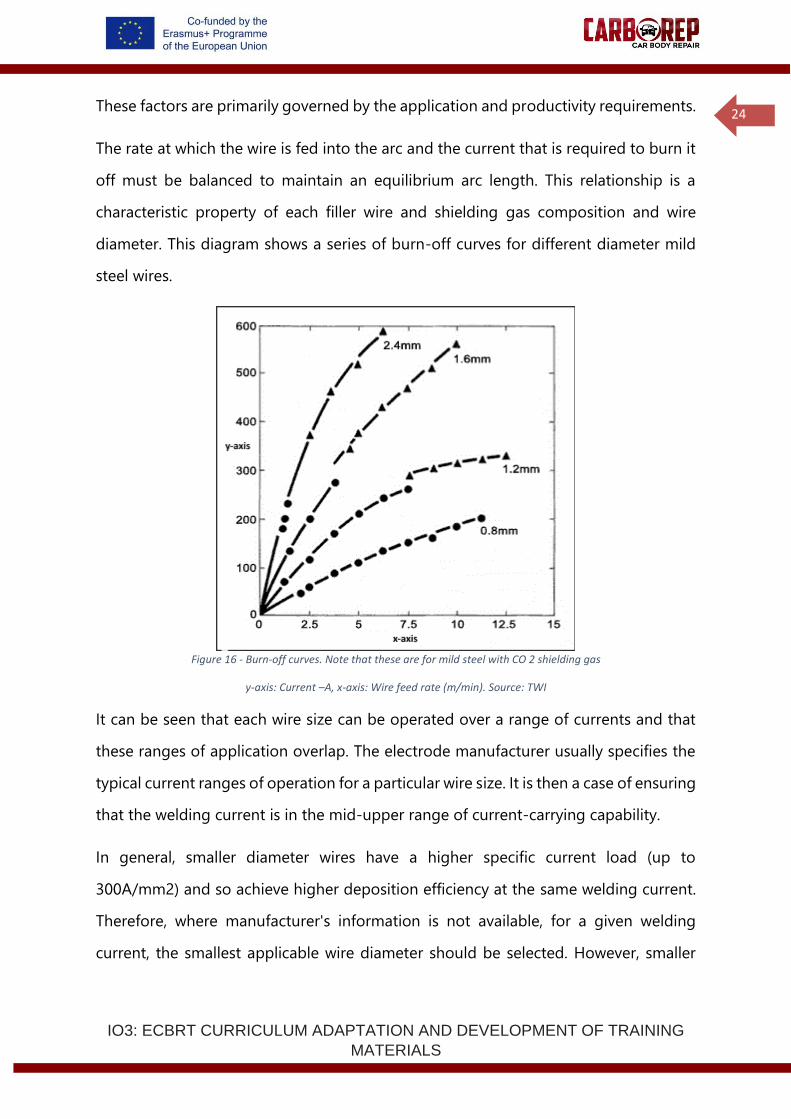
The rate at which the wire is fed into the arc and the current that is required to burn it
off must be balanced to maintain an equilibrium arc length. This relationship is a
characteristic property of each filler wire and shielding gas composition and wire
diameter. This diagram shows a series of burn-off curves for different diameter mild
steel wires.
Figure 16 - Burn-off curves. Note that these are for mild steel with CO 2 shielding gas
y-axis: Current –A, x-axis: Wire feed rate (m/min). Source: TWI
It can be seen that each wire size can be operated over a range of currents and that
these ranges of application overlap. The electrode manufacturer usually specifies the
typical current ranges of operation for a particular wire size. It is then a case of ensuring
that the welding current is in the mid-upper range of current-carrying capability.
In general, smaller diameter wires have a higher specific current load (up to
300A/mm2) and so achieve higher deposition efficiency at the same welding current.
Therefore, where manufacturer's information is not available, for a given welding
current, the smallest applicable wire diameter should be selected. However, smaller
IO3: ECBRT CURRICULUM ADAPTATION AND DEVELOPMENT OF TRAINING
MATERIALS
25
wire diameters require higher wire feed speeds to reach the same currents and it may
be beyond the capability of the wire feed unit to deliver the wire consistently. The wire
is less stiff, which may itself cause feeding problems. Smaller diameter wires also cost
more than larger wires because they are more expensive to produce.
When operating near the spray transfer range, operating fluctuations, e.g. erratic wire
feed, may cause intermittent crossing of the spray threshold, which may result in
globular transfer and spatter. In this case, it may be beneficial to choose a smaller
diameter wire, which will then operate well above the spray transition current.
Larger diameter wires, e.g. 1.4, 1.6, and 2.4mm, are capable of operating at higher
current levels and therefore give higher deposition rates if the joint design permits
such high currents, e.g. fillet welding in the PA position.
It is also necessary to consider the dynamic output characteristics of the power source.
For example, if there is no inductance control on the power source, better process
stability may be achieved by selecting a smaller diameter wire rather than a larger
diameter wire and tolerate spatter.
Storage of wires
It is essential that all consumable wires are in first-class condition. This is particularly
so for MAG welding where process stability relies on consistency of wire feed and
electrical contact. In order that this can be achieved and maintained, the following
control measures may be necessary:
• The wire should be in a clean condition with the minimum of grease and drawn-
in dirt. Therefore, when not in use, reels should be returned to the stores and
not left on equipment for long periods. Dust covers should be used, if available.
• If a wire has been left on the equipment for a short period of time, it is good
practice to run off at least one layer of wire to remove the worst of any surface
oxidation or contamination that may have occurred.
• For storage, consideration should be given to factors such as humidity,
temperature, stacking and identification, and recording of issue/return and date
IO3: ECBRT CURRICULUM ADAPTATION AND DEVELOPMENT OF TRAINING
MATERIALS
26
of purchase. Reels should be stored at a temperature above the dewpoint of
the local area. Particular attention should be paid to storage and identification
of partly used reels of wire in fabrication shops or on site.
On receipt, it is common to record the trade name, brand name, specification, grade
and batch numbers of wires. The need for adequate records will depend on the
criticality of the job to be welded.
Gases
For welding all grades of steels, controlled addition of oxygen or carbon dioxide (CO2)
to generate a stable arc and give good droplet wetting. Because these additions react
with the molten metal they are referred to as active gases, hence metal active gas
(MAG) welding is the technical term when referring to welding steels.
Shielding gases for arc welding and brazing are specified according to EN ISO 14175
'Welding consumables – Gases and gas mixtures gases for fusion welding and allied
processes’. However, many welders are more familiar with the trade names of gases
they use, rather than the composition or classification. The classification code can be
used to identify the shielding gas on a welding procedure specification, but the range
of approval is normally restricted to the nominal composition used in the procedure
qualification test.
100%CO2
CO2 gas cannot sustain spray transfer as the ionisation potential of the gas is too
high it gives very good penetration but promotes globular droplet transfer also a
very unstable arc and lots of spatter.
Argon +15-20%CO2
The percentage of CO2 or oxygen depends on the type of steel being welded and
the mode of metal transfer used. Argon has a much lower ionisation potential
and can sustain spray transfer above 24 welding volts. Argon gives a very stable arc,
IO3: ECBRT CURRICULUM ADAPTATION AND DEVELOPMENT OF TRAINING
MATERIALS
27
little spatter but lower penetration than CO2. Argon and 5-20%CO2 gas mixtures give
the benefit of both gases, ie good penetration with a stable arc and very little spatter.
CO2 gas is much cheaper than argon or its mixtures and is widely used for carbon
and some low alloy steels.
Argon +1-5%CO2
Widely used for stainless steels and some low alloy steels. At least 2% CO2 or 1% O2 in
argon is required to stabilise the arc roots and to promote wetting of the weld pool.
Many shielding gas mixtures for carbon and low alloy steels contain both CO2 and O2.
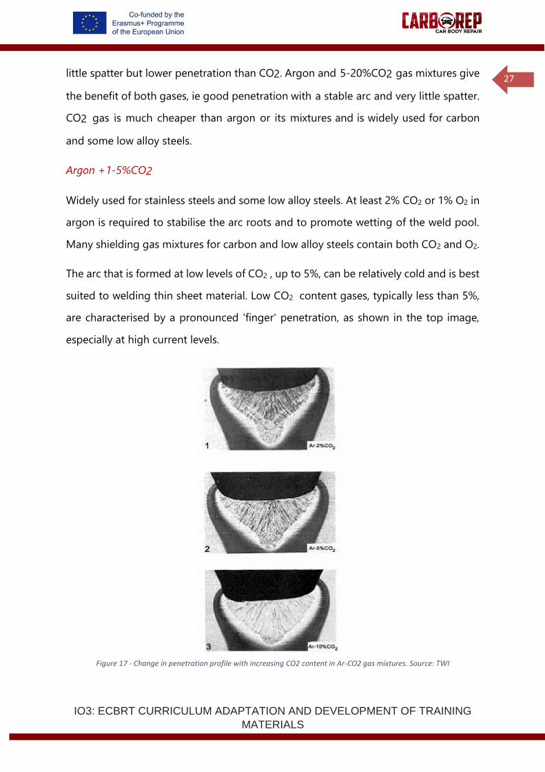
The arc that is formed at low levels of CO2 , up to 5%, can be relatively cold and is best
suited to welding thin sheet material. Low CO2 content gases, typically less than 5%,
are characterised by a pronounced 'finger' penetration, as shown in the top image,
especially at high current levels.
Figure 17 - Change in penetration profile with increasing CO2 content in Ar-CO2 gas mixtures. Source: TWI
IO3: ECBRT CURRICULUM ADAPTATION AND DEVELOPMENT OF TRAINING
MATERIALS
28
Argon-CO2 mixtures produce a relatively sharp threshold level and stable spray
transfer mode compared with pure CO2. The minimum argon content to support axial
spray transfer is 80% argon, 20% CO2. It also follows that for pulse transfer, mixtures
with 20%CO2 or less should be used. Argon-CO mixtures are also more tolerant of the
voltage setting and generate substantially lower spatter levels. The surface tension of
the weld pool is reduced.
Since the degree of melting increases significantly with increase in CO2 content, thicker
material is normally welded with up to 25% CO2. The weld penetration increases with
increasing CO2 content and the extent of the finger decreases. However, the level of
spatter also increases with the CO2 content, so that a general purpose gas mixture of
10 to 15% CO 2 provides a compromise between fusion profile and stability for general
purpose welding. Typical flow rates are 12-18l/min.
Argon-O2 mixtures
The addition of oxygen is an alternative to CO2 for stabilising the arc and promoting
wetting-in of the weld pool; 2% O2 provides an oxidising atmosphere equivalent to
5%CO2 and produces similar benefits of greater stability and smoother weld bead
profile. Oxygen generates a stiffer arc than CO2 , which can help to minimise
undercutting; it is therefore ideally suited to the spray transfer mode, having a well-
defined transition level. At high current levels, it produces the characteristic 'finger'
type weld bead penetration.
Argon-helium-CO2 -O2 mixtures
Helium has a higher ionisation potential than argon. This produces a higher arc
voltage, and the arc formed is considerably hotter than with argon-based gases. When
substituted for argon in argon-CO2 mixtures, this can often promote higher welding
speeds and improve the weld bead penetration profile (deeper bowl-shaped
IO3: ECBRT CURRICULUM ADAPTATION AND DEVELOPMENT OF TRAINING
MATERIALS
29
penetration and a flatter surface profile). These mixtures are particularly suitable for
mechanised welding, but are more expensive than argon-based mixtures.
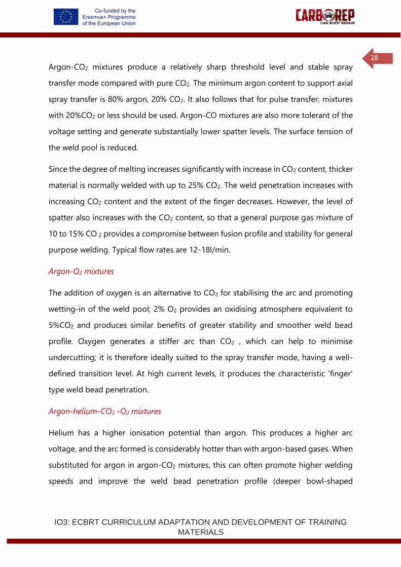
This chart summarises the gas mixtures for different transfer modes and steel
thicknesses; blue is a cooler gas mixture; red is a hotter mixture.
Figure 18 - Active shielding gas mixtures for MAG welding of carbon, C-Mn and low alloy steels. Blue is a cooler and red a hotter mixture gas. Source: TWI
A hotter gas mixture minimises the risk of lack of fusion defects in dip transfer, and
cold lapping defects in spray transfer. Hotter gas mixtures are likely to yield higher
speeds, and are suitable for thick material, mechanised applications and downhand
applications, particularly fillet welds. Colder mixtures are suited for thin sheet and all-
positional welding with low heat input transfer modes. When using a low heat input
welding condition on thicker material, it is advisable to select a hotter gas mixture to
help minimise the risk of defects. When using spray transfer, there is a minimal risk of
lack of fusion defects, and a colder gas mixture may be beneficial to optimise metal
transfer and bead profile.
For pulse transfer, a compromise between achieving good metal transfer
characteristics and reducing the risk of lack of fusion defects, but maintaining low heat
input and arc stability, is necessary.
Pulse transfer
Argon-CO2 mixtures
Dip transfer
Argon-CO2 mixtures
CO2
Spray transfer
Argon-CO2 mixtures
Argon-O2 mixtures
Material Thickness (mm)
IO3: ECBRT CURRICULUM ADAPTATION AND DEVELOPMENT OF TRAINING
MATERIALS
30
Gas mixtures with helium instead of argon give a hotter arc, more fluid weld pool
and better weld profile. These quaternary mixtures permit higher welding speeds but
may not be suitable for thin sections.
Selection of shielding gases for MAG welding and brazing is primarily dependent on
the material type and metal transfer mode (and hence material thickness). However, it
is not always possible to specify precise compositional ranges for gas mixtures for
specific materials or applications. The choice of gas is often a compromise between
achieving stable metal transfer, minimising the risk of defects and obtaining the
desired bead profile, penetration and considering any metallurgical effects of
oxidation. The economics of shielding gas selection should also be considered,
because considerable benefits in welding speed and reduction in reject rates may be
achievable by choosing a more expensive gas mixture. The shielding gas specified in
the welding procedure or repair instruction should always be used.
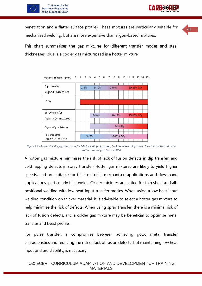
Shielding gas mixtures for MAG welding - summary
Metal Shielding gas
Reaction behaviour
Characteristics
Carbon
steel
Argon-CO 2 Slightly
oxidising
Increasing CO 2 content gives hotter arc, improved arc
stability, deeper penetration, transition from 'finger'-type
to bowl-shaped penetration profile, more fluid weld pool
giving flatter weld bead with good wetting, increased
spatter levels, better toughness than CO 2 . Min 80% Argon
for axial spray transfer. General purpose mixture: Argon-
10-15%CO 2 .
Argon-O 2 Slightly
oxidising
Stiffer arc than Ar-CO 2 mixtures, minimises undercutting,
suited to spray transfer mode, lower penetration than Ar-
CO 2 mixtures, 'finger'-type weld bead penetration at high
current levels. General purpose mixture: Argon-3%CO 2 .
Argon-
helium-CO 2
Slightly
oxidising
Substitution of helium for argon gives hotter arc, higher
arc voltage, more fluid weld pool, flatter bead profile,
more bowl-shaped and deeper penetration profile and
higher welding speeds, compared with Ar-CO 2 mixtures.
High cost.
CO 2 Oxidising Arc voltages 2-3V higher than Ar-CO 2 mixtures, best
penetration, higher welding speeds, dip transfer or buried
arc technique only, narrow working range, high spatter
levels, low cost.
Table 1 – Summary.
IO3: ECBRT CURRICULUM ADAPTATION AND DEVELOPMENT OF TRAINING
MATERIALS
31
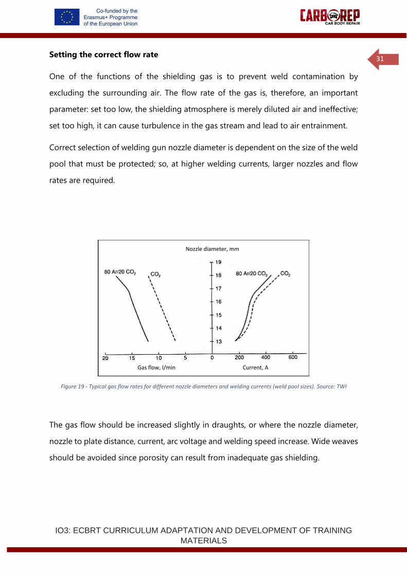
Setting the correct flow rate
One of the functions of the shielding gas is to prevent weld contamination by
excluding the surrounding air. The flow rate of the gas is, therefore, an important
parameter: set too low, the shielding atmosphere is merely diluted air and ineffective;
set too high, it can cause turbulence in the gas stream and lead to air entrainment.
Correct selection of welding gun nozzle diameter is dependent on the size of the weld
pool that must be protected; so, at higher welding currents, larger nozzles and flow
rates are required.
Figure 19 - Typical gas flow rates for different nozzle diameters and welding currents (weld pool sizes). Source: TWI
The gas flow should be increased slightly in draughts, or where the nozzle diameter,
nozzle to plate distance, current, arc voltage and welding speed increase. Wide weaves
should be avoided since porosity can result from inadequate gas shielding.
Nozzle diameter, mm
Gas flow, l/min Current, A
IO3: ECBRT CURRICULUM ADAPTATION AND DEVELOPMENT OF TRAINING
MATERIALS
32
In the workshop
Welding equipment
Visual check to ensure the welding equipment is in good condition.
Electrode wire
The diameter, specification and quality of wire are the main inspection headings. The
level of de-oxidation of the wire is an important factor with single, double and triple
de-oxidised wires being available.
The higher the level of de-oxidants in the wire, the lower the chance of porosity in the
weld. The quality of the wire winding, copper coating and temper are also important
factors in minimising wire feed problems.
Drive rolls and liner
Check the drive rolls are the correct size for the wire and that the pressure is hand
tight or just sufficient to drive the wire. Excess pressure will deform the wire to an
ovular shape making it very difficult to drive through the liner, resulting in arcing
in the contact tip and excessive wear of the contact tip and liner.
Check that the liner is the correct type and size for the wire. One size of liner
generally fits two sizes of wire, ie 0.6 and 0.8, 1 and 1.2, 1.4 and 1.6mm diameter.
Steel liners are used for steel wires and Teflon for aluminium wires.
Contact tip
Check the contact tip is the right size for the wire being driven. Check the contact tip
frequently for the amount of wear, and replace the contact tip regularly.
Connections
Check that all connections in the welding circuit are secure and that cables are in
good condition.
IO3: ECBRT CURRICULUM ADAPTATION AND DEVELOPMENT OF TRAINING
MATERIALS
33
Gas and gas flow rate
The type of gas used is extremely important to MAG welding and brazing, as is the
flow rate from the cylinder which must be adequate to give effective shielding.
Confirm the gas composition against the welding/brazing procedure requirements
and set the gas flow rate.
Other variable welding parameters
Checks should be made for correct wire feed speed, voltage, speed of travel and
all other essential variables of the process given on the approved welding/brazing
procedure.
Safety checks
Check t he current carrying capacity or duty cycle of equipment and electrical
insulation. Check that extraction systems are functioning correctly and
positioned to avoid exposure to fumes. Check the availability and condition of all
necessary PPE and screens.
Welder
Check that the welder is qualified to weld the procedure being used.
Setting up the workshop for welding and brazing:
Documentation: Which documents do you need to have before welding and brazing?
Health, safety and environment documents:
..................................................................................................................................................................
..................................................................................................................................................................
Welding and brazing documents:
..................................................................................................................................................................
..................................................................................................................................................................
IO3: ECBRT CURRICULUM ADAPTATION AND DEVELOPMENT OF TRAINING
MATERIALS
34
Personal Protective Equipment: List the PPE you require and perform the pre-use
inspection.
..................................................................................................................................................................
..................................................................................................................................................................
..................................................................................................................................................................
Ventilation and extraction equipment: Perform the pre-use inspection, position and
operate the equipment.
Notes:
MAG welding/brazing equipment: Perform the pre-use inspection, check
maintenance and calibration records, disassemble and reassemble the welding torch,
and install the consumable.
Notes:
IO3: ECBRT CURRICULUM ADAPTATION AND DEVELOPMENT OF TRAINING
MATERIALS
35
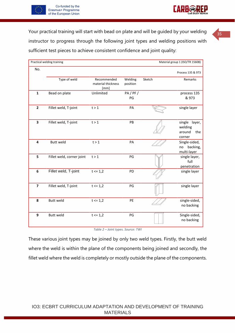
Your practical training will start with bead on plate and will be guided by your welding
instructor to progress through the following joint types and welding positions with
sufficient test pieces to achieve consistent confidence and joint quality:
Practical welding training Material group 1 (ISO/TR 15608)
No. Process 135 & 973
Type of weld Recommended material thickness
[mm]
Welding position
Sketch Remarks
1 Bead on plate Unlimited PA / PF / PG
process 135 & 973
2 Fillet weld, T-joint t > 1 PA
single layer
3 Fillet weld, T-joint t > 1 PB
single layer, welding around the corner
4 Butt weld t > 1 PA
Single-sided, no backing, multi-layer
5 Fillet weld, corner joint t > 1 PG
single layer, full
penetration not required
135
6 Fillet weld, T-joint t <= 1,2 PD
single layer
7 Fillet weld, T-joint t <= 1,2 PG
single layer
8 Butt weld t <= 1,2 PE
single-sided, no backing
9 Butt weld t <= 1,2 PG
Single-sided, no backing
Table 2 – Joint types. Source: TWI
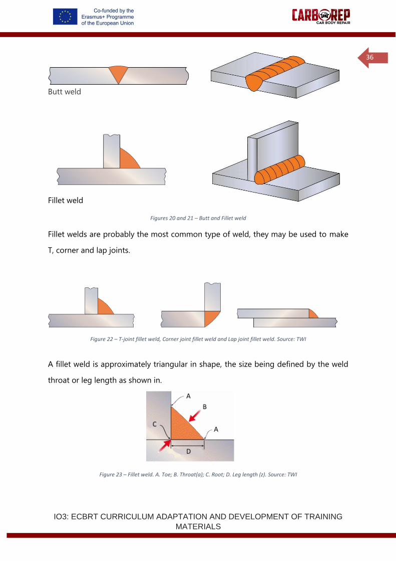
These various joint types may be joined by only two weld types. Firstly, the butt weld
where the weld is within the plane of the components being joined and secondly, the
fillet weld where the weld is completely or mostly outside the plane of the components.
IO3: ECBRT CURRICULUM ADAPTATION AND DEVELOPMENT OF TRAINING
MATERIALS
36
Butt weld
Fillet weld
Figures 20 and 21 – Butt and Fillet weld
Fillet welds are probably the most common type of weld, they may be used to make
T, corner and lap joints.
Figure 22 – T-joint fillet weld, Corner joint fillet weld and Lap joint fillet weld. Source: TWI
A fillet weld is approximately triangular in shape, the size being defined by the weld
throat or leg length as shown in.
Figure 23 – Fillet weld. A. Toe; B. Throat(a); C. Root; D. Leg length (z). Source: TWI
IO3: ECBRT CURRICULUM ADAPTATION AND DEVELOPMENT OF TRAINING
MATERIALS
37
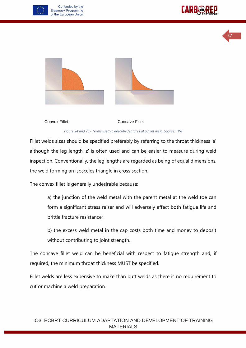
Convex Fillet Concave Fillet
Figure 24 and 25 - Terms used to describe features of a fillet weld. Source: TWI
Fillet welds sizes should be specified preferably by referring to the throat thickness 'a'
although the leg length 'z' is often used and can be easier to measure during weld
inspection. Conventionally, the leg lengths are regarded as being of equal dimensions,
the weld forming an isosceles triangle in cross section.
The convex fillet is generally undesirable because:
a) the junction of the weld metal with the parent metal at the weld toe can
form a significant stress raiser and will adversely affect both fatigue life and
brittle fracture resistance;
b) the excess weld metal in the cap costs both time and money to deposit
without contributing to joint strength.
The concave fillet weld can be beneficial with respect to fatigue strength and, if
required, the minimum throat thickness MUST be specified.
Fillet welds are less expensive to make than butt welds as there is no requirement to
cut or machine a weld preparation.
IO3: ECBRT CURRICULUM ADAPTATION AND DEVELOPMENT OF TRAINING
MATERIALS
38
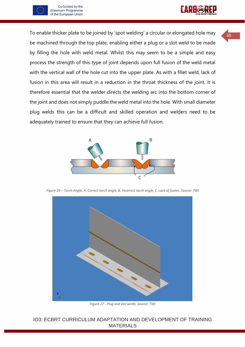
To enable thicker plate to be joined by 'spot welding' a circular or elongated hole may
be machined through the top plate, enabling either a plug or a slot weld to be made
by filling the hole with weld metal. Whilst this may seem to be a simple and easy
process the strength of this type of joint depends upon full fusion of the weld metal
with the vertical wall of the hole cut into the upper plate. As with a fillet weld, lack of
fusion in this area will result in a reduction in the throat thickness of the joint. It is
therefore essential that the welder directs the welding arc into the bottom corner of
the joint and does not simply puddle the weld metal into the hole. With small diameter
plug welds this can be a difficult and skilled operation and welders need to be
adequately trained to ensure that they can achieve full fusion.
Figure 26 – Torch Angle. A. Correct torch angle, B. Incorrect torch angle, C. Lack of fusion. Source: TWI
Figure 27 - Plug and slot welds. Source: TWI
IO3: ECBRT CURRICULUM ADAPTATION AND DEVELOPMENT OF TRAINING
MATERIALS
39
Since the strength of the plug or slot weld is determined by the throat it may not be
necessary to fill the hole completely unless the weld must be flush with the surface of
the plate for cosmetic reasons. Besides being unnecessary from the point of view of
joint strength, a completely filled hole will have high residual stresses. These may cause
unacceptable distortion and will increase the risk of cold cracking in carbon and low
alloy steels.
1.2.2 MAG Welding and GMAW’s Processes
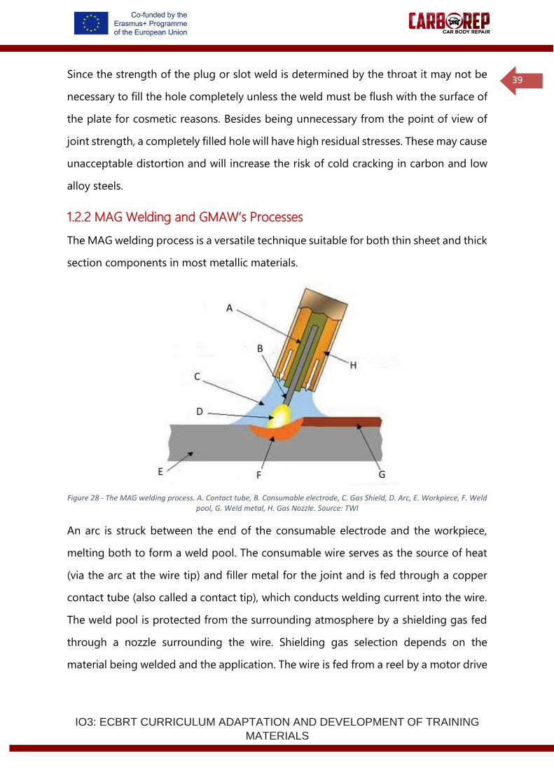
The MAG welding process is a versatile technique suitable for both thin sheet and thick
section components in most metallic materials.
Figure 28 - The MAG welding process. A. Contact tube, B. Consumable electrode, C. Gas Shield, D. Arc, E. Workpiece, F. Weld pool, G. Weld metal, H. Gas Nozzle. Source: TWI
An arc is struck between the end of the consumable electrode and the workpiece,
melting both to form a weld pool. The consumable wire serves as the source of heat
(via the arc at the wire tip) and filler metal for the joint and is fed through a copper
contact tube (also called a contact tip), which conducts welding current into the wire.
The weld pool is protected from the surrounding atmosphere by a shielding gas fed
through a nozzle surrounding the wire. Shielding gas selection depends on the
material being welded and the application. The wire is fed from a reel by a motor drive
IO3: ECBRT CURRICULUM ADAPTATION AND DEVELOPMENT OF TRAINING
MATERIALS
40
and the welder moves the welding gun or torch along the joint line. The process offers
high productivity and is economical because the consumable wire is continuously fed.
The MAG process uses semi-automatic equipment. It is called semi-automatic because
the wire feed rate and arc length are controlled automatically but the travel speed and
wire position are under manual control.
The Gas Metal Arc Weld Brazing process is a variant of the MAG welding process,
where the MAG equipment is used with braze welding consumables. These filler wires
are normally of the silicon or phosphor-bronze type for braze welding steels. The braze
welding consumables melt at a lower temperature than the parent material and form
a brazed joint, where the filler metal wets the surface of the plate rather than fusing
with it. The joint strength is not as good as that of the parent material. The process is
often used for cosmetic welds in thin sheet material, where low heat input is desirable.
The most common application of the Gas Metal Arc Weld Brazing process in
automotive repair is typically used in areas that are difficult to access with a resistance
spot welding gun or for attaching replacement body panels, when drilling or
machining through the top sheet is used to produce a plug or socket weld.
1.2.3 Specifications of Gas Metal Arc Weld Brazing
The braze welding process is a variant of the MAG welding process, where the majority
of the process-essential variables are identical to conventional MAG welding
processes. However, in the braze welding process, the melting point of the filler wires
is significantly lower with relation to the melting point of the parent material. During
the arc welding process, the filler wire melts at temperatures typically over 1600°C,
whereas for brazing the wire melts at less than 1000°C.
As in the standard MAG welding process, a continuously fed wire electrode is melted
by an arc formed between the electrode and the workpiece, but no significant melting
or fusion of the parent metal occurs because of the lower temperature. The molten
IO3: ECBRT CURRICULUM ADAPTATION AND DEVELOPMENT OF TRAINING
MATERIALS
41
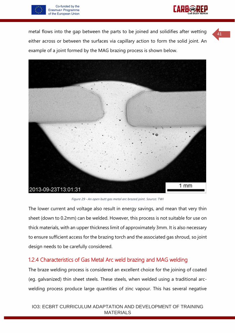
metal flows into the gap between the parts to be joined and solidifies after wetting
either across or between the surfaces via capillary action to form the solid joint. An
example of a joint formed by the MAG brazing process is shown below.
Figure 29 - An open butt gas metal arc brazed joint. Source: TWI
The lower current and voltage also result in energy savings, and mean that very thin
sheet (down to 0.2mm) can be welded. However, this process is not suitable for use on
thick materials, with an upper thickness limit of approximately 3mm. It is also necessary
to ensure sufficient access for the brazing torch and the associated gas shroud, so joint
design needs to be carefully considered.
1.2.4 Characteristics of Gas Metal Arc weld brazing and MAG welding
The braze welding process is considered an excellent choice for the joining of coated
(eg. galvanized) thin sheet steels. These steels, when welded using a traditional arc-
welding process produce large quantities of zinc vapour. This has several negative
IO3: ECBRT CURRICULUM ADAPTATION AND DEVELOPMENT OF TRAINING
MATERIALS
42
effects. Firstly, the vapour can cause defects in the weld such as pores or gas voids
reducing the strength of the welded joint. Secondly, the loss of zinc from the surface
of the parent plate results in a significant reduction in its corrosion resistant properties,
sometimes necessitating re-coating of the steel.
The welding process also introduces significant heat into the base metal, resulting in
significant distortion and a wide heat-affected zone. These effects can be reduced by
using a brazing process, due to the lower heat needed to melt the filler wires compared
to a standard welding process. The reduced damage to the zinc coating means that it
will still provide galvanic protection to the base steel even in the 1–2mm region around
the joint where the coating has been lost. This also produces less zinc containing
welding fume.
A TWI investigation into the use of arc brazing for the joining of 1mm-thick galvanised
DP600 sheet with a CuSi3 filler metal showed that, with the correct joint fit-up and
suitable process parameters, the strength of the joint is capable of overmatching the
ultimate tensile strength (UTS) of the parent plate. The adhesion of the braze material
on the top and bottom surfaces of the DP600 plate provides sufficient strength such
that the overall joint has a UTS greater than 600MPa, despite the UTS of the filler being
approximately 350MPa.
The joining process and consumables specified in the welding or brazing procedure or
repair instruction must always be used.
1.2.5 Braze welding preparation in car body repair
Ensure the surfaces to be welded are metallically clean, while taking care to not
damage any coating. A range of joint configurations can be used, including butt, lap
and tee-fillets. The joint design needs to be constructed so as to provide good wetting
and capillary action of the braze material and to ensure that the stresses are not placed
directly into the braze metal as tensile stresses. The stress needs to be supported
through the adhesive surfaces of the braze metal to the parent sheet. A gap on the
IO3: ECBRT CURRICULUM ADAPTATION AND DEVELOPMENT OF TRAINING
MATERIALS
43
order of 0.5–1mm between the components to be joined will allow successful flow of
the braze metal into the joint, improving adhesion and increasing the strength of the
joint. However, it is important to note that too large a joint gap, especially for butt
joints, will result in all of the stress on the component being realised as a tensile
strength in the braze filler, resulting in joint failure at a lower UTS.
The power source is likely to be operating at lower output than would usually be used
for standard MAG welding and can also be used with pulsed or direct current. A short
circuiting arc is typically used. Because of the nature of the brazing process, the braze
weld bead will not have as shallow an appearance as a weld bead. It is not necessary
to increase the current to flatten out the braze bead as this will reduce the value of
brazing as a low-heat-input process.
It is necessary to very carefully select and control the process parameters as the high
fluidity of the copper-based braze results in a much more “moveable” weld pool. This
can easily over-penetrate or form an undesirable bead appearance if not controlled.
The torch is used in a “pushing” orientation (of approximately 70–80°) to allow
preheating of the plate and removal of any coating ahead of the weld pool, with the
torch positioned symmetrically between the two joint surfaces (eg at 45° for a tee-
fillet). This torch angle also reduces the probability of excessive penetration either
through the gap or into the parent metal.
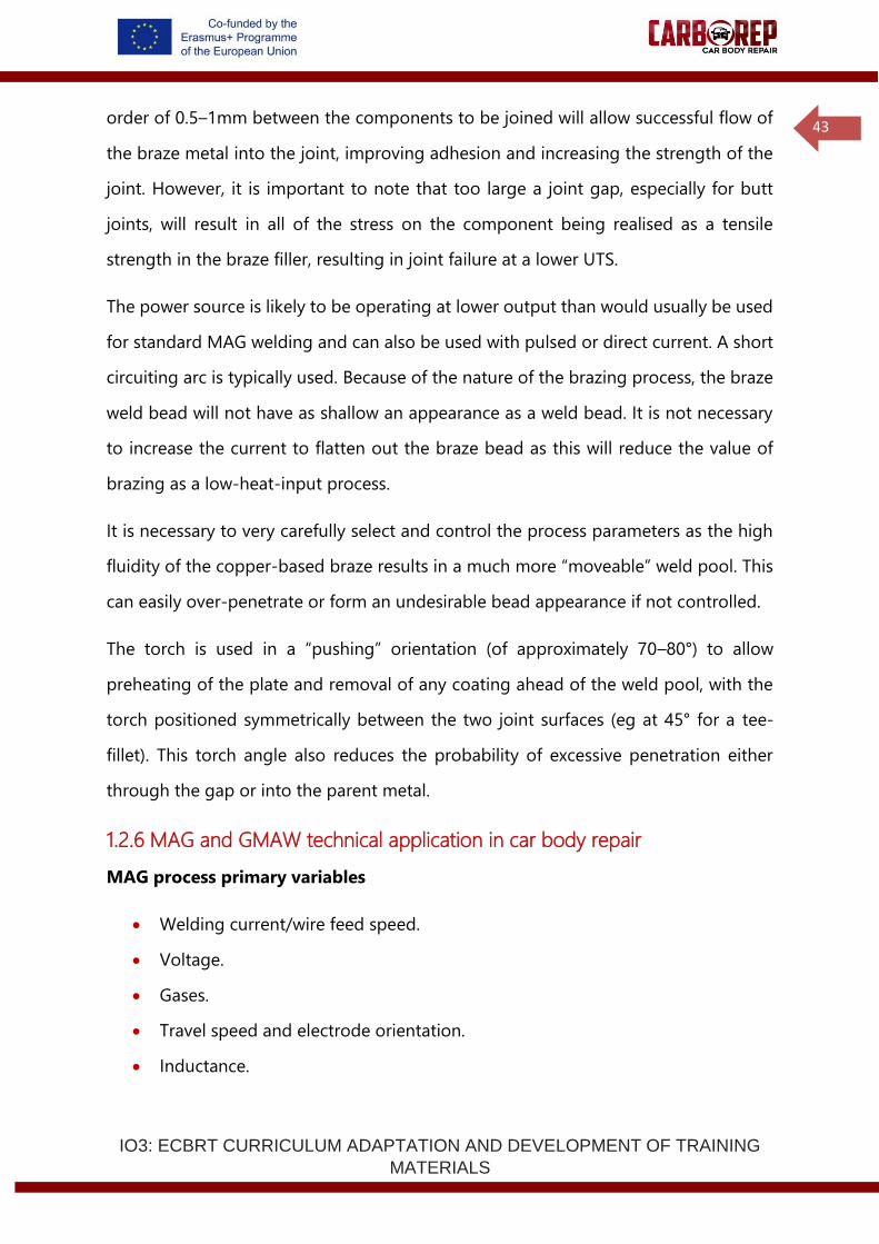
1.2.6 MAG and GMAW technical application in car body repair
MAG process primary variables
• Welding current/wire feed speed.
• Voltage.
• Gases.
• Travel speed and electrode orientation.
• Inductance.
IO3: ECBRT CURRICULUM ADAPTATION AND DEVELOPMENT OF TRAINING
MATERIALS
44
• Contact tip to work distance (CTWD).
• Nozzle to work distance.
• Shielding gas nozzle.
• Type of metal transfer.
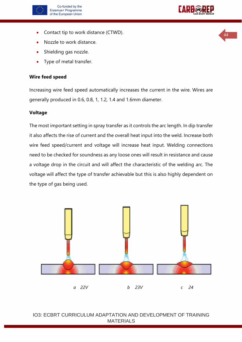
Wire feed speed
Increasing wire feed speed automatically increases the current in the wire. Wires are
generally produced in 0.6, 0.8, 1, 1.2, 1.4 and 1.6mm diameter.
Voltage
The most important setting in spray transfer as it controls the arc length. In dip transfer
it also affects the rise of current and the overall heat input into the weld. Increase both
wire feed speed/current and voltage will increase heat input. Welding connections
need to be checked for soundness as any loose ones will result in resistance and cause
a voltage drop in the circuit and will affect the characteristic of the welding arc. The
voltage will affect the type of transfer achievable but this is also highly dependent on
the type of gas being used.
a 22V b 23V c 24
IO3: ECBRT CURRICULUM ADAPTATION AND DEVELOPMENT OF TRAINING
MATERIALS
45
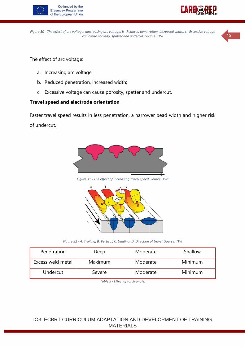
Figure 30 - The effect of arc voltage: aIncreasing arc voltage; b Reduced penetration, increased width; c Excessive voltage can cause porosity, spatter and undercut. Source: TWI
The effect of arc voltage:
a. Increasing arc voltage;
b. Reduced penetration, increased width;
c. Excessive voltage can cause porosity, spatter and undercut.
Travel speed and electrode orientation
Faster travel speed results in less penetration, a narrower bead width and higher risk
of undercut.
Figure 31 - The effect of increasing travel speed. Source: TWI
Figure 32 - A. Trailing, B. Vertical, C. Leading, D. Direction of travel. Source: TWI
Penetration Deep Moderate Shallow
Excess weld metal Maximum Moderate Minimum
Undercut Severe Moderate Minimum
Table 3 - Effect of torch angle.
IO3: ECBRT CURRICULUM ADAPTATION AND DEVELOPMENT OF TRAINING
MATERIALS
46
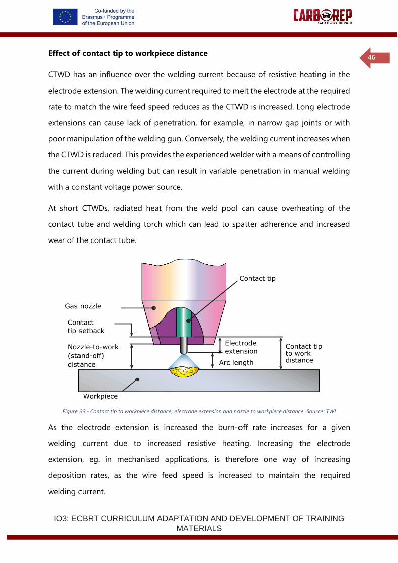
Effect of contact tip to workpiece distance
CTWD has an influence over the welding current because of resistive heating in the
electrode extension. The welding current required to melt the electrode at the required
rate to match the wire feed speed reduces as the CTWD is increased. Long electrode
extensions can cause lack of penetration, for example, in narrow gap joints or with
poor manipulation of the welding gun. Conversely, the welding current increases when
the CTWD is reduced. This provides the experienced welder with a means of controlling
the current during welding but can result in variable penetration in manual welding
with a constant voltage power source.
At short CTWDs, radiated heat from the weld pool can cause overheating of the
contact tube and welding torch which can lead to spatter adherence and increased
wear of the contact tube.
Figure 33 - Contact tip to workpiece distance; electrode extension and nozzle to workpiece distance. Source: TWI
As the electrode extension is increased the burn-off rate increases for a given
welding current due to increased resistive heating. Increasing the electrode
extension, eg. in mechanised applications, is therefore one way of increasing
deposition rates, as the wire feed speed is increased to maintain the required
welding current.
Contact tip
Gas nozzle
Contact
tip setback
Nozzle-to-work
(stand-off)
distance
Electrode
extension
Arc length
Contact tip to work distance
Workpiece
IO3: ECBRT CURRICULUM ADAPTATION AND DEVELOPMENT OF TRAINING
MATERIALS
47
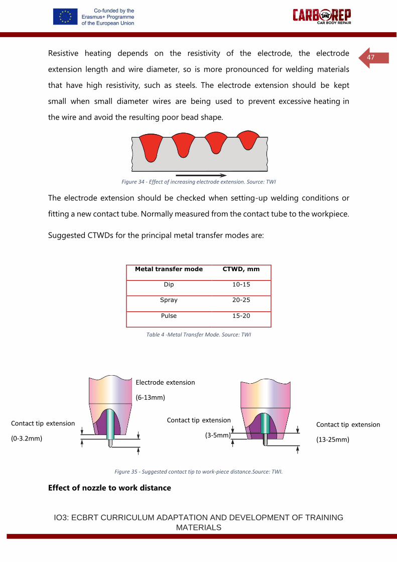
Resistive heating depends on the resistivity of the electrode, the electrode
extension length and wire diameter, so is more pronounced for welding materials
that have high resistivity, such as steels. The electrode extension should be kept
small when small diameter wires are being used to prevent excessive heating in
the wire and avoid the resulting poor bead shape.
Figure 34 - Effect of increasing electrode extension. Source: TWI
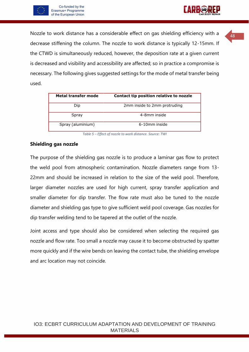
The electrode extension should be checked when setting-up welding conditions or
fitting a new contact tube. Normally measured from the contact tube to the workpiece.
Suggested CTWDs for the principal metal transfer modes are:
Table 4 -Metal Transfer Mode. Source: TWI
Figure 35 - Suggested contact tip to work-piece distance.Source: TWI.
Effect of nozzle to work distance
Metal transfer mode CTWD, mm
Dip 10-15
Spray 20-25
Pulse 15-20
Contact tip extension
(0-3.2mm)
Electrode extension
(6-13mm)
(
6
-
1
3
m
m
)
Contact tip extension
(3-5mm)
Contact tip extension
(13-25mm)
IO3: ECBRT CURRICULUM ADAPTATION AND DEVELOPMENT OF TRAINING
MATERIALS
48
Nozzle to work distance has a considerable effect on gas shielding efficiency with a
decrease stiffening the column. The nozzle to work distance is typically 12-15mm. If
the CTWD is simultaneously reduced, however, the deposition rate at a given current
is decreased and visibility and accessibility are affected; so in practice a compromise is
necessary. The following gives suggested settings for the mode of metal transfer being
used.
Metal transfer mode Contact tip position relative to nozzle
Dip 2mm inside to 2mm protruding
Spray 4-8mm inside
Spray (aluminium) 6-10mm inside
Table 5 – Effect of nozzle to work distance. Source: TWI
Shielding gas nozzle
The purpose of the shielding gas nozzle is to produce a laminar gas flow to protect
the weld pool from atmospheric contamination. Nozzle diameters range from 13-
22mm and should be increased in relation to the size of the weld pool. Therefore,
larger diameter nozzles are used for high current, spray transfer application and
smaller diameter for dip transfer. The flow rate must also be tuned to the nozzle
diameter and shielding gas type to give sufficient weld pool coverage. Gas nozzles for
dip transfer welding tend to be tapered at the outlet of the nozzle.
Joint access and type should also be considered when selecting the required gas
nozzle and flow rate. Too small a nozzle may cause it to become obstructed by spatter
more quickly and if the wire bends on leaving the contact tube, the shielding envelope
and arc location may not coincide.
IO3: ECBRT CURRICULUM ADAPTATION AND DEVELOPMENT OF TRAINING
MATERIALS
49
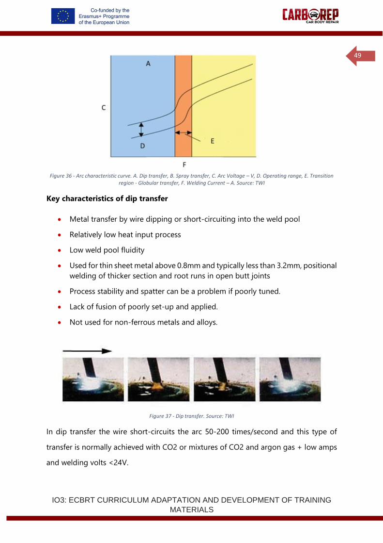
Figure 36 - Arc characteristic curve. A. Dip transfer, B. Spray transfer, C. Arc Voltage – V, D. Operating range, E. Transition
region - Globular transfer, F. Welding Current – A. Source: TWI
Key characteristics of dip transfer
• Metal transfer by wire dipping or short-circuiting into the weld pool
• Relatively low heat input process
• Low weld pool fluidity
• Used for thin sheet metal above 0.8mm and typically less than 3.2mm, positional
welding of thicker section and root runs in open butt joints
• Process stability and spatter can be a problem if poorly tuned.
• Lack of fusion of poorly set-up and applied.
• Not used for non-ferrous metals and alloys.
Figure 37 - Dip transfer. Source: TWI
In dip transfer the wire short-circuits the arc 50-200 times/second and this type of
transfer is normally achieved with CO2 or mixtures of CO2 and argon gas + low amps
and welding volts <24V.
IO3: ECBRT CURRICULUM ADAPTATION AND DEVELOPMENT OF TRAINING
MATERIALS
50
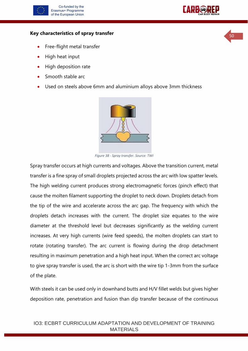
Key characteristics of spray transfer
• Free-flight metal transfer
• High heat input
• High deposition rate
• Smooth stable arc
• Used on steels above 6mm and aluminium alloys above 3mm thickness
Figure 38 - Spray transfer. Source: TWI
Spray transfer occurs at high currents and voltages. Above the transition current, metal
transfer is a fine spray of small droplets projected across the arc with low spatter levels.
The high welding current produces strong electromagnetic forces (pinch effect) that
cause the molten filament supporting the droplet to neck down. Droplets detach from
the tip of the wire and accelerate across the arc gap. The frequency with which the
droplets detach increases with the current. The droplet size equates to the wire
diameter at the threshold level but decreases significantly as the welding current
increases. At very high currents (wire feed speeds), the molten droplets can start to
rotate (rotating transfer). The arc current is flowing during the drop detachment
resulting in maximum penetration and a high heat input. When the correct arc voltage
to give spray transfer is used, the arc is short with the wire tip 1-3mm from the surface
of the plate.
With steels it can be used only in downhand butts and H/V fillet welds but gives higher
deposition rate, penetration and fusion than dip transfer because of the continuous
IO3: ECBRT CURRICULUM ADAPTATION AND DEVELOPMENT OF TRAINING
MATERIALS
51
arc heating. It is mainly used for steel plate thicknesses >3mm but has limited use for
positional welding due to the potential large weld pool involved.
Key characteristics pulsed transfer
• Free-flight droplet transfer without short-circuiting over the entire working
range
• Very low spatter
• Lower heat input than spray transfer
• Reduced risk of lack of fusion compared with dip transfer
• Control of weld bead profile for dynamically loaded parts
• Process control/flexibility
• Enables use of larger diameter, less expensive wires with thinner plates – more
easily fed (particular advantage for aluminium welding)
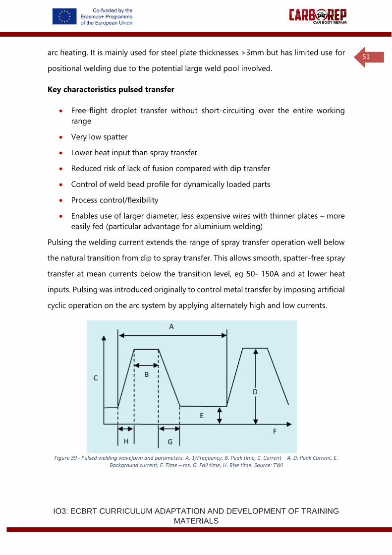
Pulsing the welding current extends the range of spray transfer operation well below
the natural transition from dip to spray transfer. This allows smooth, spatter-free spray
transfer at mean currents below the transition level, eg 50- 150A and at lower heat
inputs. Pulsing was introduced originally to control metal transfer by imposing artificial
cyclic operation on the arc system by applying alternately high and low currents.
Figure 39 - Pulsed welding waveform and parameters. A. 1/Frequency, B. Peak time, C. Current – A, D. Peak Current, E. Background current, F. Time – ms, G. Fall time, H. Rise time. Source: TWI
IO3: ECBRT CURRICULUM ADAPTATION AND DEVELOPMENT OF TRAINING
MATERIALS
52
A low background current (typically 20-80A) is supplied to maintain the arc, keep the
wire tip molten, give stable anode and cathode roots and maintain average current
during the cycle. Droplet detachment occurs during a high current pulse at current
levels above the transition current level. The pulse of current generates very high
electromagnetic forces which cause a strong pinch effect on the metal filament
supporting the droplet the droplet is detached and projected across the arc gap. Pulse
current and current density must be sufficiently high to ensure that spray transfer (not
globular) always occurs so that positional welding can be used.
Pulse transfer uses pulses of current to fire a single globule of metal across the arc gap
at a frequency of 50-300 pulses/second. It is a development of spray transfer that gives
positional welding capability for steels, combined with controlled heat input, good
fusion and high productivity and may be used for all sheet steel thickness >1mm, but
is mainly used for positional welding of steels >6mm.
Key characteristics of globular transfer
• Irregular metal transfer
• Medium heat input
• Medium deposition rate
• Risk of spatter
• Not widely used in the UK can be used for mechanised welding of medium
thickness (typically 3-6mm) steel in the flat (PA) position.
Synergic
Is a term meaning working together and was originally designed to establish correct
pulse parameters in MIG/MAG welding over a range of wire diameters and gas
mixtures. Manually adjusting pulse parameters was problematic with many variables
to adjust; pulse peak, pulse time, background current and background time.
IO3: ECBRT CURRICULUM ADAPTATION AND DEVELOPMENT OF TRAINING
MATERIALS
53
Consequently, to arrive at the correct arc condition was time consuming and fraught
with errors.
With the advancement in electronically controlled power sources and subsequent CPU
inverter controlled systems, it has allowed manufacturers to produce a one knob
control system. Therefore, all parameters previously mentioned can be controlled via
a one knob control operation to establish the correct arc condition as determined by
the manufacturers of the power source. In essence, as the knob is turned the wire feed
increases, possibly voltage (and all pulse parameters) change to keep a balanced arc
condition.
The manufacturers, have predetermined synergic curves based on material type, wire
diameter and gas mixture. To facilitate set up, this information is programmed in by
the user and a unique curve is produced based on the inputs. The user can then adjust,
via one knob control, up and down the synergic curve. Most machines however have
an option to adjust the voltage of the synergic curve if required. In addition, once an
acceptable welding condition is found, most manufacturers have the ability to save to
memory for later re- call.
The globular transfer range occupies the transitional range of arc voltage between
free-flight and fully short-circuiting transfer. Irregular droplet transfer and arc
instability are inherent, particularly when operating near the transition threshold. In
globular transfer a molten droplet several times the electrode diameter forms on the
wire tip, gravity eventually detaches it when its weight overcomes surface tension
forces and transfer takes place often with excessive spatter. Before transfer the arc
wanders and its cone covers a large area, dissipating energy.
There is a short duration short-circuit when the droplet contacts with the molten pool
but rather than causing droplet transfer it occurs as a result of it. Although the short-
circuit is of very short duration, some inductance is necessary to reduce spatter,
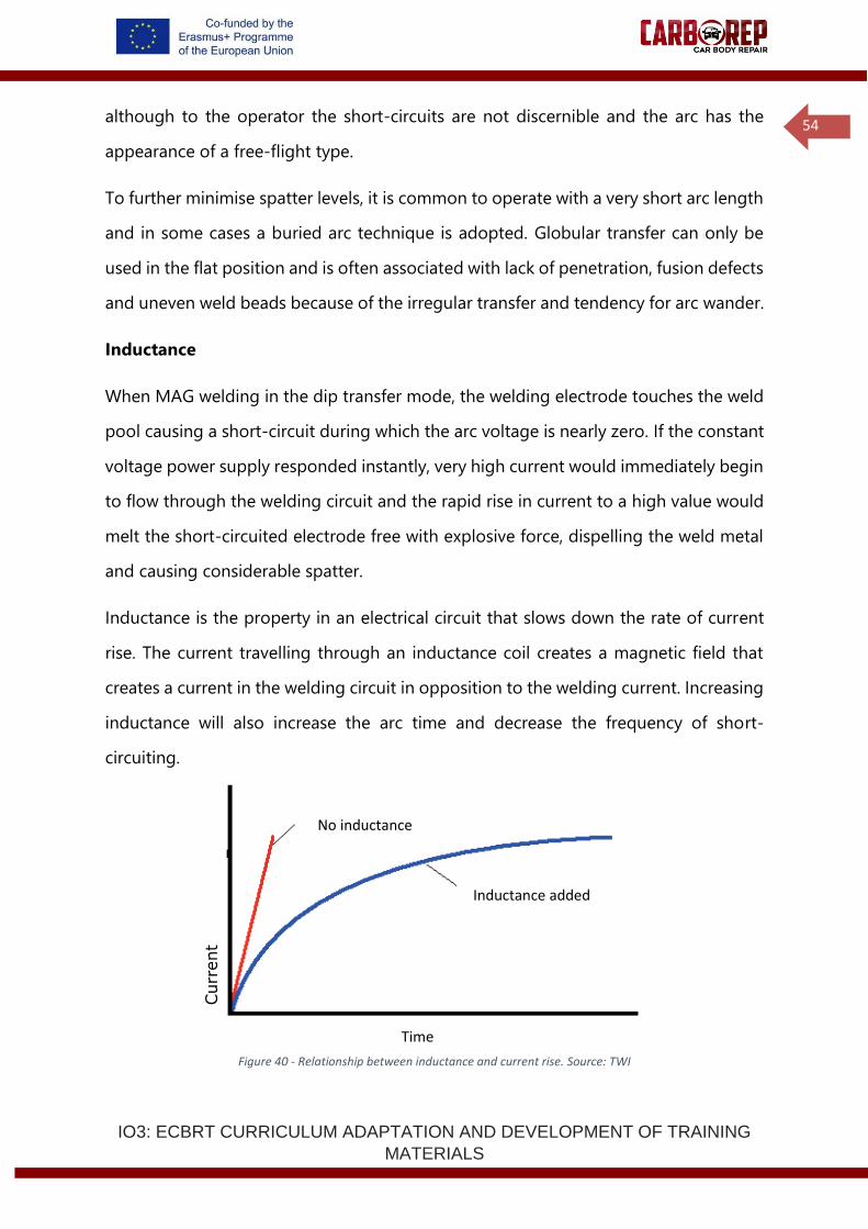
IO3: ECBRT CURRICULUM ADAPTATION AND DEVELOPMENT OF TRAINING
MATERIALS
54
although to the operator the short-circuits are not discernible and the arc has the
appearance of a free-flight type.
To further minimise spatter levels, it is common to operate with a very short arc length
and in some cases a buried arc technique is adopted. Globular transfer can only be
used in the flat position and is often associated with lack of penetration, fusion defects
and uneven weld beads because of the irregular transfer and tendency for arc wander.
Inductance
When MAG welding in the dip transfer mode, the welding electrode touches the weld
pool causing a short-circuit during which the arc voltage is nearly zero. If the constant
voltage power supply responded instantly, very high current would immediately begin
to flow through the welding circuit and the rapid rise in current to a high value would
melt the short-circuited electrode free with explosive force, dispelling the weld metal
and causing considerable spatter.
Inductance is the property in an electrical circuit that slows down the rate of current
rise. The current travelling through an inductance coil creates a magnetic field that
creates a current in the welding circuit in opposition to the welding current. Increasing
inductance will also increase the arc time and decrease the frequency of short-
circuiting.
Figure 40 - Relationship between inductance and current rise. Source: TWI
Curr
ent
No inductance
Time
Inductance added

IO3: ECBRT CURRICULUM ADAPTATION AND DEVELOPMENT OF TRAINING
MATERIALS
55
There is an optimum value of inductance for each electrode feed rate. Too little
inductance results in excessive spatter, too much and current will not rise fast enough
and the electrode is not heated sufficiently causing the electrode to stub into the base
metal. Modern electronic power sources automatically set inductance to give a smooth
arc and metal transfer.
1.2.7 Health and Safety, and Environmental Safety
Working in a safe manner, to protect yourself, others and the vehicle you are working
on, is an essential consideration in any welding operation. The responsibility for
safety is on all individuals but especially the welders, not only for their own safety,
but also to avoid endangering other people. Your employer has an important
responsibility for ensuring that hea l th , safety and environment (HSE) legislation is
complied with and safe working practices are implemented. If you cannot assure your
own safety and the safety of others in the work area, then stop welding and do not
start welding again until the risk has been controlled.
Your employer should ensure compliance with all appropriate documents, for
example:
• Legislation – EU OSH Directives.
• Standards – OHSAS 18001.
• Company Health, Safety and Environment Management Systems.
• Work instructions – permits to work, risk assessment documents, etc.
The workshop environment
The employer needs to ensure that the lighting conditions are adequate for the work
undertaken - giving extra lighting where necessary. Welders stand for long periods of
time, since they must keep a very steady hand position, and this means that they can
become quite cold if the workshop is not sufficiently well heated. Conversely in hot
weather, the environment can become unbearably hot, and the welder must wear
IO3: ECBRT CURRICULUM ADAPTATION AND DEVELOPMENT OF TRAINING
MATERIALS
56
protective clothing. Both overheating and underheating can cause discomfort, and a
loss of efficiency and productivity.
Housekeeping is extremely important to avoid slips, trips and falls, damage to
equipment and fire.
There are many aspects of welding safety that the welder needs to consider:
• Electric shock.
• Electromagnetic Fields
• Heat and light.
• Fumes and gases.
• Noise.
• Gas cylinder handling and storage.
• Working at height or in restricted access.
• Mechanical hazards: trips, falls, cuts, impact from heavy objects.
Electric shock
Contact with metal parts that are electrically live can cause injury or death because
of the effect of the shock upon the body or because of a fall as a result of the reaction
to electric shock.
The electric shock hazard associated with arc welding may be either from the
primary 230 or 460V mains supply or from the output voltage at 60-100V. Primary
voltage shock is very hazardous because it is much greater than the secondary
voltage of the welding equipment. Electric shock from the input voltage can
occur by touching a lead inside the welding equipment with the power to the
welder while the body or hand touches the welding equipment case or other
earthed metal. Only a qualified electrician should remove the casing of a welding
power source. Residual circuit devices (RCDs) connected to circuit breakers of
IO3: ECBRT CURRICULUM ADAPTATION AND DEVELOPMENT OF TRAINING
MATERIALS
57
sufficient capacity will help protect personnel from the danger of primary electric
shock.
The transformed power is available from terminals on the front of the welding set.
Heavy-duty cables are attached to these terminals to carry the welding current to
the torch or electrode holder and to bring a return path from the work or metal
workbench to the other terminal. This return is often referred to as the earth or
ground and there may be secondary earthing arranged so that the work is at zero
volts. Secondary voltage shock occurs when touching a part of the electrode circuit
– perhaps a damaged area on the electrode cable – while another part of the body
touches the other side of the welding circuit (the work or welding earth) at the
same time.
Whilst most welding equipment is unlikely to exceed an OCV of 100V, electric shock,
even at this level, can be serious. The welding circuit should be fitted with low
voltage safety devices to minimise the potential of secondary electric shock.
It is important that the welding cables can carry the maximum possible output of
the welding set without overheating as overheating can damage the insulation,
leading to an increased risk of electrical shock.
Installation of welding equipment should be carried out by suitably qualified staff who
must check that the equipment is suitable for the operation and connected in
accordance with the manufacturer's recommendations. The welder is responsible for
checking the equipment (cable, welding torch and coupling devices) daily for damage
and reporting defects. All external connections should be clean and tight and checked
each time a reconnection is made. The welding return clamp should be connected
directly to the workpiece, as close as possible to the point of welding.
Welder actions for safe practice and avoidance of electric shock:
• Do not wear jewellery (especially rings) or metallic watch straps
IO3: ECBRT CURRICULUM ADAPTATION AND DEVELOPMENT OF TRAINING
MATERIALS
58
• Wear protective clothing including insulating safety boots, gloves, boots and
overalls
• Check daily, and after each reconnection, that all external connections are clean
and tight
• Stand or kneel on a mat of insulating material which should be kept dry
• Place the welding power source outside the working environment
• Ensure qualified support staff are in close proximity outside the working space
to give first aid and switch off the electrical supply
• When welding outside, check the power source protection rating is adequate
for the environment and do not weld in the rain without a suitable cover
• When welding the vehicle directly, ensure that the vehicle is electrically safe; a
competent auto electrician has isolated the batteries and any hybrid power
systems, and disconnected sensitive electronics units
Electromagnetic Fields
Welding processes may produce low frequency fields that have a detrimental effect on
the mental and physical health of the exposed workers. The possible effects include
stimulation of muscles, nerves or sensory organs and transitory symptoms such as
vertigo or retinal phosphenes. These effects may affect the ability of the worker to
work safely.
Electromagnetic fields may be sub-divided into magnetic and electric fields and for
most welding processes, it is the magnetic field which is significant.
Exposure to electromagnetic fields may cause direct biophysical effects, including:
• thermal effects such as tissue heating.
• non-thermal effects such as the stimulation of muscles, nerves or sensory
organs.
• Limb currents.
Indirect effects of EMF include:
• interference with medical electronic devices such as pacemakers.
IO3: ECBRT CURRICULUM ADAPTATION AND DEVELOPMENT OF TRAINING
MATERIALS
59
• projectile risk from ferromagnetic objects in static magnetic fields.
• initiation of detonators.
• ignition of flammable materials by sparks caused by induced fields.
• contact currents.
Welder actions for safe practice and avoidance of welding EMF:
• Follow the guidance from the employer’s workplace assessment
• Do not wrap welding cables around body
• Do not stand in coiled welding cables
Heat
As MAG welding relies on melting metal to effect a joint, it follows that the metal
will in part be very hot. All metals conduct heat to a greater or lesser degree so the
area heated to a temperature that will cause skin burns is much larger than the weld
bead itself. It is a wise precaution to assume that all metal on a welding workbench
or adjacent to a weld in a car body is hot. Temperature indicating sticks should
be used to check that material is cool enough to handle. It is not safe to pat metal
with the bare hand to check its temperature.
The welding arc creates sparks, with the potential to cause flammable materials near
the welding area to ignite and cause fires. The welding area should be clear of all
combustible materials and it is good practice for all personnel working in the vicinity
of welding to know where the nearest fire extinguishers are and the correct type of
fire extinguisher to use if a fire does break out.
Welding may also produce spatter, globules of molten metal expelled from the weld
area. These can cause serious burns, so protective clothing, such as welding
gloves, flame retardant coveralls and leathers must be worn around any welding
operation to protect against heat and sparks. It is most important that traps in
IO3: ECBRT CURRICULUM ADAPTATION AND DEVELOPMENT OF TRAINING
MATERIALS
60
clothing are avoided. Trousers should not have turn-ups and should not be tucked
into boots – very serious injury can occur if spatter drops inside a work boot.
Radiant heat from welding can be quite intense, particularly when welding at high
current and duty cycle is taking place. Sufficient air movement is required to keep
the welder at a sensible temperature especially important when working in restricted
access areas where reflected heat will intensify the effect. Welders should also take
water regularly to avoid potential dehydration.
Welder actions for safe practice and avoidance of effects of welding heat:
• Ensure that appropriate PPE is available, fit for use and correctly worn
• Ensure that combustible trim is removed from the vicinity of the joint and that
the car is protected, where necessary, with fire resistant blankets
Light
Light radiation is emitted by the welding arc in three principal ranges:
Type Wavelength, nanometres
Infra-red (heat) >700
Visible light 400-700
Ultra-violet radiation <400
Table 6 – principal ranges of light radiation.
Ultra-violet radiation (UV) light
All arc processes generate UV and excess exposure causes skin inflammation and
possibly skin cancer or permanent eye damage. However, the main risk amongst
welders and others in welding workshops is inflammation of the cornea and
conjunctiva, commonly known as arc eye or flash.
Arc eye is caused by UV radiation which damages the outmost protective layer of cells
in the cornea. Gradually the damaged cells die and fall off the cornea exposing highly
sensitive nerves in the underlying cornea to the comparatively rough inner part of the
eyelid. This causes intense pain, usually described as sand in the eye. The pain becomes
even more acute if the eye is then exposed to bright light.

IO3: ECBRT CURRICULUM ADAPTATION AND DEVELOPMENT OF TRAINING
MATERIALS
61
Arc eye develops some hours after exposure, which may not even have been noticed.
The sand in the eye symptom and pain usually lasts for 12-24 hours, longer in more
severe cases. Fortunately, it is almost always a temporary condition. In the unlikely
event of prolonged and frequently repeated exposures, permanent damage can occur.
Treatment of arc eye is simple: rest in a dark room. A qualified person or hospital
casualty department can administer various soothing anaesthetic eye drops which can
provide almost instantaneous relief. Prevention is better than cure and wearing
safety glasses with side shields will considerably reduce the risk of this condition.
The welder should always have a full face screen with the approved shade of
protective lens for the process in hand.
Effect of ultra-violet light on the skin
The UV from arc processes does not produce the attractive browning effect of suntan;
but results in acute reddening and irritation caused by changes in the minute surface
blood vessels. In extreme cases, the skin may be severely burned and blisters form. The
reddened skin may die and flake off in a day or so. Where there has been intense
prolonged or frequent exposure, skin cancers can develop.
Visible light
Intense visible light particularly approaching UV or blue light wavelengths passes
through the cornea and lens and can dazzle and, in extreme cases, damage the
network of optically sensitive nerves on the retina. Wavelengths of visible light
approaching the infra-red have slightly different effects but can produce similar
symptoms. Effects depend on the duration and intensity of exposure and to some
extent, upon the individual's natural reflex action to close the eye and exclude the
incident light. Normally this dazzling does not produce a long-term effect.
Infra-red radiation (IR)
IO3: ECBRT CURRICULUM ADAPTATION AND DEVELOPMENT OF TRAINING
MATERIALS
62
Infra-red radiation is of longer wavelength than the visible light frequencies and is
perceptible as heat. The main hazard to the eyes is that prolonged exposure (over a
matter of years) causes a gradual but irreversible opacity of the lens. Fortunately, the
IR radiation emitted by normal welding arc causes damage only within a comparatively
short distance from the arc. There is an immediate burning sensation in the skin
surrounding the eyes should they be exposed to arc heat. The natural human reaction
is to move or cover up to prevent the skin heating, which also reduces eye exposure.
Arc radiation
The welder must be protected from light radiation emitted from the arc by a hand or
head shield and protective clothing. The shield is fitted with filter glass, dark enough
to absorb infrared and ultraviolet rays. Filter glasses conform to EN 169 and are graded
according to a shade number. This specifies the amount of light allowed to pass
through - the lower the number, the lighter the filter. The shade number is selected
according to welding process and current level.
Welder actions for safe practice and avoidance of effects of welding light:
• Do not strike an arc unless welders and welders’ assistants are wearing suitable
protective clothing and eye protection
• Do not strike an arc unless other workers in the vicinity and passers-by are
protected by opaque or properly filtered screens around your work area
Fumes and gases
Fume is a mixture of particles generated by vaporisation, condensation and oxidation
of substances transferred through the welding arc. The particles are very small and
remain suspended in the air for long periods, where they may be breathed. Small
particles are respirable; they may penetrate the innermost regions of the lung where
they have the most potential to do harm. If inhaled. Welding fume is carcinogenic and
there is no safe exposure level for inhalation.
IO3: ECBRT CURRICULUM ADAPTATION AND DEVELOPMENT OF TRAINING
MATERIALS
63
Toxic fume may be created also from paint finishes, coatings, adhesive bond lines and
urethane foam in the vicinity of the welded joint.
Carbon monoxide (CO) and CO2 may be generated in MAG welding from the shielding
gas, with CO2 undergoing reaction in the vicinity of the arc to form CO.
CO is the more hazardous of the two gases and can cause a reduction in the oxygen
carrying capacity of the blood that can be fatal. In lower concentrations it causes
headache and dizziness, nausea and weakness. However, the amounts of CO and CO2
generated by welding processes are small and generally do not present an exposure
problem.
Other gases may be introduced to the work area from shielding gas. Remember that
gases that are heavier than air are likely to collect in inspection pits.
The following aspects are likely to influence the degree to which the welder is exposed
to fume and gases:
• welding position
• location and type of workplace
Thus, welders using the same process may be exposed to different levels of fume. The
risks for each job should, therefore, be assessed individually.
Welding position
The welding position (flat, vertical, horizontal or overhead) and proximity of the welder
to the fume plume affect exposure. As the welder naturally bends over the workpiece,
the flat position induces the highest level of fume in the breathing zone. The welder
should adopt a working position which ensures that his head is away from the plume.
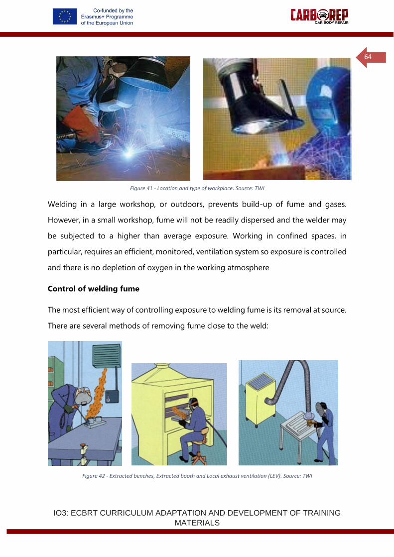
IO3: ECBRT CURRICULUM ADAPTATION AND DEVELOPMENT OF TRAINING
MATERIALS
64
Figure 41 - Location and type of workplace. Source: TWI
Welding in a large workshop, or outdoors, prevents build-up of fume and gases.
However, in a small workshop, fume will not be readily dispersed and the welder may
be subjected to a higher than average exposure. Working in confined spaces, in
particular, requires an efficient, monitored, ventilation system so exposure is controlled
and there is no depletion of oxygen in the working atmosphere
Control of welding fume
The most efficient way of controlling exposure to welding fume is its removal at source.
There are several methods of removing fume close to the weld:
Figure 42 - Extracted benches, Extracted booth and Local exhaust ventilation (LEV). Source: TWI
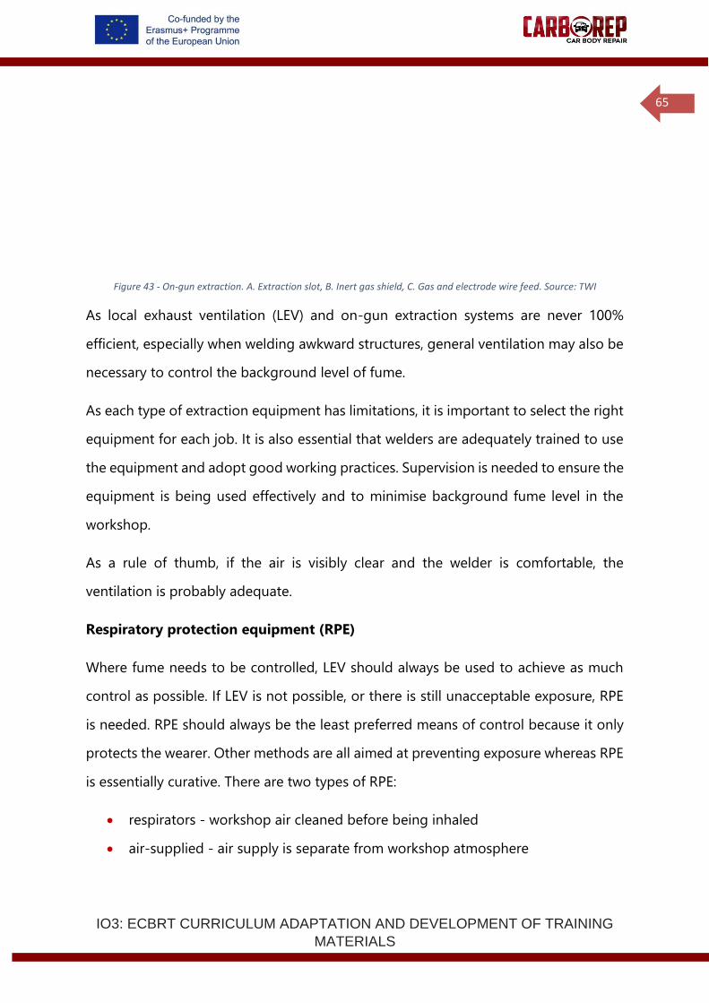
IO3: ECBRT CURRICULUM ADAPTATION AND DEVELOPMENT OF TRAINING
MATERIALS
65
Figure 43 - On-gun extraction. A. Extraction slot, B. Inert gas shield, C. Gas and electrode wire feed. Source: TWI
As local exhaust ventilation (LEV) and on-gun extraction systems are never 100%
efficient, especially when welding awkward structures, general ventilation may also be
necessary to control the background level of fume.
As each type of extraction equipment has limitations, it is important to select the right
equipment for each job. It is also essential that welders are adequately trained to use
the equipment and adopt good working practices. Supervision is needed to ensure the
equipment is being used effectively and to minimise background fume level in the
workshop.
As a rule of thumb, if the air is visibly clear and the welder is comfortable, the
ventilation is probably adequate.
Respiratory protection equipment (RPE)
Where fume needs to be controlled, LEV should always be used to achieve as much
control as possible. If LEV is not possible, or there is still unacceptable exposure, RPE
is needed. RPE should always be the least preferred means of control because it only
protects the wearer. Other methods are all aimed at preventing exposure whereas RPE
is essentially curative. There are two types of RPE:
• respirators - workshop air cleaned before being inhaled
• air-supplied - air supply is separate from workshop atmosphere

IO3: ECBRT CURRICULUM ADAPTATION AND DEVELOPMENT OF TRAINING
MATERIALS
66
Selection of suitable RPE will require the advice of an expert who can make the
selection based on fume concentration, presence of toxic gases and whether there is
a oxygen deficient atmosphere.
Welder actions for safe practice and avoidance of fume and gases:
• check that the ventilation and extraction equipment is working correctly and is
regularly maintained, for example, cleaning and replacing filters according to
manufacturer's recommendations
• place the extraction hood or nozzle to capture the fume without disturbing the
gas shield
• reposition the extractionhood at appropriate intervals to ensure fume continues
to be effectively extracted
• if possible, remove paint, coating or insulation from the workpiece before
welding
• before using RPE, consult expert in choice of respirator
• get personally fitted with an RPE to ensure that it provides adequate protection
• follow your training in use of an RPE and its maintenance and cleaning
• use the systems put in place by your management for control of equipment and
training
Noise
Exposure to loud noise can permanently damage hearing, cause stress and increase
blood pressure. Working in a noisy environment for long periods can contribute to
tiredness, nervousness and irritability. If the noise exposure is greater than 85 A-
weighted decibels, averaged over an eight-hour period then hearing protection must
be worn and annual hearing tests carried out. The employer has the responsibility of
ensuring that workers wear the protection. If noise levels are between 80 and 85dB(A)
averaged over eight hours, hearing protection must be available and given to workers
if they ask for it.
Normal welding operations are not associated with excessive noise level problems. The
noise associated with welding is usually due to ancillary operations such as chipping,

IO3: ECBRT CURRICULUM ADAPTATION AND DEVELOPMENT OF TRAINING
MATERIALS
67
grinding and hammering. Hearing protection must be worn when carrying out, or
when working in the vicinity of, these operations.
Gas handling and storage
The cylinders contain gas at up to 300 bar and care must be exercised to ensure that
they cannot fall and sever the valve from the top. The sudden release of energy turns
the cylinder into a high powered missile capable of passing through block walls,
demonstrated most graphically by the Discovery Channel’s Mythbusters. A video has
been posted on YouTube (www.youtube.com/watch?v=ejEJGNLTo84).
Shielding gas cylinders must be in purpose built cradles with secure chaining to avoid
toppling. One person should not handle gas cylinders on their own, as they weigh up
to 100kg and there is a real risk of loss of control. Transportation around a workshop
should be in a trolley designed for the purpose.
Pressure regulators must be fitted to gas cylinders to extract the gas at a usable
pressure. Regulators must be appropriate for the job: rated at least as high as the
maximum pressure of the cylinder and designated for the specific gas.
Tubes carrying the gas to the welding torch should be pressure hoses designed for the
job. Hoses should be checked for leaks by using diluted detergent around all fittings.
Leakage of shielding gas is not as safety critical as leakage of fuel gas, but the weld
quality can be compromised if leaks develop. For a similar reason, hoses should be
purged for some minutes prior to starting work to eliminate any moisture adsorbed
onto the inner wall.
Mechanical hazards
The environment in which a welder works has a number of hazards not specific to the
welding process itself. Manual handling of heavy awkward metal components is often
required. Thinner, lighter metal sheet may have sharp edges. Slips, trips and falls may
be more likely as welding often requires thick cables to be spread across the floor.
IO3: ECBRT CURRICULUM ADAPTATION AND DEVELOPMENT OF TRAINING
MATERIALS
68
Standard workshop safety and protection practice should be used to counter these
problems. Welders need training in materials handling, both manual and with
mechanical lifting assistance; protective gloves, helmets, overalls and boots must be
worn; cabling on the floor should be minimised and clearly signed or marked as a trip
hazard.
There are hazards that are a direct result of the joining process, as during welding,
sparks and molten metal can be ejected. These are most common in arc welding but
can also occur in resistance processes. Personal protective equipment (PPE) must be
worn by the welder. All clothing should be fire resistant and use of leather aprons,
jackets, chaps, etc is recommended.
Grinding is commonly used in preparing metal for welding and during cleaning and
rectification of deposited metal. Wheel and angle grinders are favourite tools for their
speed of removal of material. These create a hazard, not only for the operator but for
adjacent and passing personnel, as the ejected material may be thrown some distance.
Obviously the operator needs adequate protection with clothing, gloves, full-face
shields and sometimes a dust mask but the whole area also needs screening with
curtains to protect others. Fireproof blankets may be used to protect the vehicle from
grinding sparks, and care needs to be taken to prevent cross contamination between
vehicles and materials in the workshop.
One of the more serious dangers is from the persistent use of hand-held portable
power tools, such as grinders, sanders, impact wrenches, and air chisels, which can lead
to long-term illness – hand-arm vibration syndrome, also known as ‘white finger’ or
‘dead hand’. Employers are encouraged to purchase only power tools designed and
constructed to reduce the risk of vibration, and are required to conduct an assessment
and identify measures to eliminate or reduce the risk. You are required to use these
power tools only as instructed, and you should report any symptoms, includinmg

IO3: ECBRT CURRICULUM ADAPTATION AND DEVELOPMENT OF TRAINING
MATERIALS
69
tingling and numbness in fingers, not being able to feel things properly, loss of
strength in hands, fingertips going white, and becoming red and painful on recovery.
• Use the appropriate personal protective equipment and check it is fit for
purpose before carrying out welding/brazing operations.
• Protect the vehicle and its contents effectively when carrying out
welding/brazing operations.
• Prepare material and align to enable suitable join to be achieved. Mating
flanges must be treated following manufacturer’s procedure before joining.
• Select, set up and use the correct tools and equipment for carrying out
welding/brazing operations.
• Ensure that the tools, equipment and Personal Protective Equipment (PPE) you
require are in a safe working condition.
• Set up your equipment to carry out welding/brazing operations, checking
suitability of gas/filler wire and size for material to be joined, parameters are set
correctly, consumables are correct, feed rollers and welding tips are in good
condition.
• Carry out welding/brazing operations following recognised repair methods, test
procedures and provide test coupons on equivalent material in accordance with
relevant standards, manufacturer’s specifications, methods and procedures,
your workplace procedures and all health, safety and legal requirements.
• Avoid damaging other components, panels and surfaces on the vehicle and the
surrounding work area.
• Recognise when your weld/braze is not forming correctly and what action needs
to
be taken.
• Carry out welding/brazing operations within the agreed timescale and report
any delays in completing your work to the relevant person(s) promptly.
• Inspect and assess weld/braze quality in accordance with specified standards.
• Check integrity of weld/braze and record the type of joint achieved on the
appropriate paper work.
• Make sure test pieces are recorded and stored.
• Dress the joint area without reducing material thickness and protect the
repaired area to inhibit corrosion where applicable.

IO3: ECBRT CURRICULUM ADAPTATION AND DEVELOPMENT OF TRAINING
MATERIALS
70
• Clean and store Personal Protective Equipment (PPE) and equipment in
appropriate manner, report any equipment maintenance or consumable
replenishment requirements to the relevant person(s)..
• Report any additional faults you notice during the course of your work to the
relevant person(s) promptly.
• Clean and restore the vehicle and work area by removing screens and protective
materials used during welding/brazing, dispose of waste in accordance with
environmental requirements.
• Complete work records accurately, in the format required and pass them to the
relevant person(s) promptly.
1st Practical Training
Practical MAG Welding Task - Metal transfer mode and inductance
• Deposit a fillet weld on a ferritic steel plate, in horizontal vertical position
(PB).
• Select optimum welding parameters, and assess the use of pulse, dip &
spray transfer modes:
(Continue on the next page)
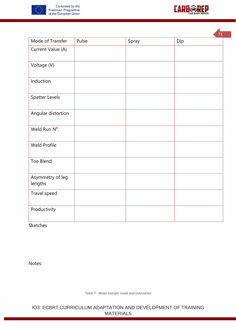
IO3: ECBRT CURRICULUM ADAPTATION AND DEVELOPMENT OF TRAINING
MATERIALS
71
Sketches
Notes:
Table 7 - Metal transfer mode and inductance
Mode of Transfer Pulse Spray Dip
Current Value (A)
Voltage (V)
Induction
Spatter Levels
Angular distortion
Weld Run N0.
Weld Profile
Toe Blend
Asymmetry of leg
lengths
Travel speed
Productivity

IO3: ECBRT CURRICULUM ADAPTATION AND DEVELOPMENT OF TRAINING
MATERIALS
72
Joint quality
• Recognise when your weld/braze is not forming correctly and apply
remedial actions:
Flaw type Sketch/description Cause Remedy
Lack of fusion
Lack of
wetting
Slag
inclusions
Asymmetrical
seam
Excessive
penetration
Insufficient
penetration
End crater
crack
Table 8 – Joint Quality.

IO3: ECBRT CURRICULUM ADAPTATION AND DEVELOPMENT OF TRAINING
MATERIALS
73
Distortion
Because welding involves highly localised heating of joint edges to fuse the material,
non-uniform stresses are set up in the component because of expansion and
contraction of the heated material. Initially, compressive stresses are created in the
surrounding cold parent metal when the weld pool is formed due to the thermal
expansion of the hot metal (heat affected zone) adjacent to the weld pool. However,
tensile stresses occur on cooling when the contraction of the weld metal and the
immediate heat affected zone is resisted by the bulk of the cold parent metal.
The magnitude of thermal stresses induced into the material can be seen by the
volume change in the weld area on solidification and subsequent cooling to room
temperature. For example, when welding CMn steel, the molten weld metal volume
will be reduced by approximately 3% on solidification and the volume of the solidified
weld metal/heat affected zone (HAZ) will be reduced by a further 7% as its temperature
falls from the melting point of steel to room temperature.
If the stresses generated from thermal expansion/contraction exceed the yield
strength of the parent metal, localised plastic deformation of the metal occurs. Plastic
deformation causes a permanent reduction in the component dimensions and distorts
the structure.
Distortion occurs in six main forms:
• Longitudinal shrinkage
• Transverse shrinkage
• Angular distortion
• Bowing and dishing
• Buckling
• Twisting
The principal features of the more common forms of distortion for butt and fillet welds
are shown next.
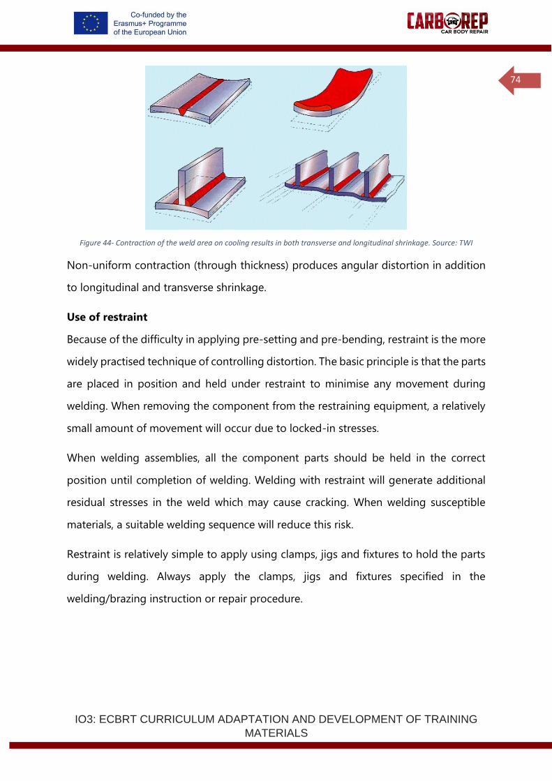
IO3: ECBRT CURRICULUM ADAPTATION AND DEVELOPMENT OF TRAINING
MATERIALS
74
Figure 44- Contraction of the weld area on cooling results in both transverse and longitudinal shrinkage. Source: TWI
Non-uniform contraction (through thickness) produces angular distortion in addition
to longitudinal and transverse shrinkage.
Use of restraint
Because of the difficulty in applying pre-setting and pre-bending, restraint is the more
widely practised technique of controlling distortion. The basic principle is that the parts
are placed in position and held under restraint to minimise any movement during
welding. When removing the component from the restraining equipment, a relatively
small amount of movement will occur due to locked-in stresses.
When welding assemblies, all the component parts should be held in the correct
position until completion of welding. Welding with restraint will generate additional
residual stresses in the weld which may cause cracking. When welding susceptible
materials, a suitable welding sequence will reduce this risk.
Restraint is relatively simple to apply using clamps, jigs and fixtures to hold the parts
during welding. Always apply the clamps, jigs and fixtures specified in the
welding/brazing instruction or repair procedure.

IO3: ECBRT CURRICULUM ADAPTATION AND DEVELOPMENT OF TRAINING
MATERIALS
75
Before, during and after welding/brazing
1. Use the appropriate personal protective equipment and check it is fit for purpose
before carrying out welding/brazing operations.
2. Protect the vehicle and its contents effectively when carrying out welding/brazing
operations.
3. Prepare material and align to enable suitable join to be achieved. Mating flanges
must be treated following manufacturer’s procedure before joining.
4. Select, set up and use the correct tools and equipment for carrying out
welding/brazing operations.
5. Ensure that the tools, equipment and Personal Protective Equipment (PPE) you
require are in a safe working condition.
6. Set up your equipment to carry out welding/brazing operations, checking suitability
of gas/filler wire and size for material to be joined, parameters are set correctly,
consumables are correct, feed rollers and welding tips are in good condition.
7. Carry out welding/brazing operations following recognised repair methods, test
procedures and provide test coupons on equivalent material in accordance with
relevant standards, manufacturer’s specifications, methods and procedures, your
workplace procedures and all health, safety and legal requirements.
8. Avoid damaging other components, panels and surfaces on the vehicle and the
surrounding work area.
9. Recognise when your weld/braze is not forming correctly and what action needs to
be taken.
10. Carry out welding/brazing operations within the agreed timescale and report any
delays in completing your work to the relevant person(s) promptly.
11. Inspect and assess weld/braze quality in accordance with specified standards.
12. Check integrity of weld/braze and record the type of joint achieved on the
appropriate paper work.
13. Make sure test pieces are recorded and stored.
14. Dress the joint area without reducing material thickness and protect the repaired
area to inhibit corrosion where applicable.
15. Clean and store Personal Protective Equipment (PPE) and equipment in appropriate
manner, report any equipment maintenance or consumable replenishment
requirements to the relevant person(s).
IO3: ECBRT CURRICULUM ADAPTATION AND DEVELOPMENT OF TRAINING
MATERIALS
76
16. Report any additional faults you notice during the course of your work to the
relevant person(s) promptly.
17. Clean and restore the vehicle and work area by removing screens and protective
materials used during welding/brazing, dispose of waste in accordance with
environmental requirements.
18. Complete work records accurately, in the format required and pass them to the
relevant person(s) promptly.
1.3 RESISTANCE SPOT WELD JOINING TECHNOLOGY
Resistance spot welding is a process for the joining of metals with heat generated by
the passage of localized current through the work piece. Resistance spot welding (EN
ISO 4063 process 21) can be applied to repair the damaged body of an automobile.
1.3.1 The Resistance Spot Welding Process
Resistance welding can be defined as a process whereby a force is applied to sheet
metal surfaces and in which the heat for welding is produced by the passage of electric
current through the electrical resistance at, and adjacent to, these surfaces. It is a well-
established process, having an excellent track record for producing quality joints in
sheet materials. In the European automotive industry alone, over 150 million resistance
spot welds are made each day. The process is used for joining sheet materials and uses
copper alloy electrodes to apply pressure and convey the electrical current through
the work pieces. Heat is developed mainly at the interface between the sheets,
eventually causing the material being welded to melt, forming a molten pool, the weld
nugget. The molten pool is constrained by the pressure applied by the electrodes and
the surrounding solid metal.
Spot welding in a high volume vehicle production line
Spot welding equipment is relatively low cost compared to other joining techniques.
The equipment requires very little maintenance and hardware can have production
lives spanning decades. The application of resistance welding is usually not technically
IO3: ECBRT CURRICULUM ADAPTATION AND DEVELOPMENT OF TRAINING
MATERIALS
77
demanding and production machines can be run successfully by relatively low skill
level staff.
Spot welding offers a number of advantages over other joining techniques, including
very high production speeds, which make it one of the cheapest production joining
processes. Welding rates of up to 40 welds per minute can be achieved in robotic spot
welding lines. The spot welding process is extremely fast, with cycle times of a fraction
of a second. This means low energy levels are required. Due to localised heating of a
small area, there is a reduced heat input into components, this minimises thermal
distortion and warping, compared to many continuous heating processes. Spot
welding is traditionally a very easy technique to automate. In automotive production
lines the car body passes between robot cells, where robots manipulate light weight
welding guns to join components. Due to the nature of spot welding, where the
electrodes apply the welding force as well as the welding current, no extra clamping
mechanisms are required. The spot welding electrodes are both clamp and welding
source, no arc welding, laser welding or adhesive process can offer in process clamping
without the introduction of extra clamping mechanisms holding the parts to join in
position.
In spot welding production a degradation of the copper electrode tips is inevitable. In
uncoated steels 100’s to 1000’s of welds can be made without a need to repair the tip
surface. But when welding zinc coated steels (as are common for automotive
components), electrode degradation occurs much more rapidly. This is due to zinc and
zinc oxide deposition on the surface of the electrode tips, which produces increasingly
rich brass phases (zinc and copper alloy). With brass, zinc and zinc oxide build-up on
the electrodes, the thermal and electrical properties are affected, the tips soften and
deform and the weld integrity slowly deteriorates. Automated electrode tip dressing
equipment is used to resolve this issue. Tip dressers employ a bladed cutter, which
removes the outer surface of the electrode and returns the shape back to the original
IO3: ECBRT CURRICULUM ADAPTATION AND DEVELOPMENT OF TRAINING
MATERIALS
78
profile. In a high volume production line, one or more tip dressing units is located
within each production cell. The robots within the cell visit the tip dresser at
predetermined intervals to maintain their electrode tips, which in turn maintains the
consistency of weld quality.
100% reliable spot weld quality is never achieved in volume production, due to the
broad range of material combinations being spot welded in a car and process
variations introduced by: electrode tip wear, component fit up, component surface
condition. Weld quality is maintained by good process control, together with periodic
testing of samples. While a number of in process monitoring systems have been
developed, there is still a desire to produce a low cost, reliable and robust in-process
weld quality monitor, in order to reduce or eliminate periodic destructive tests. Some
welding controllers incorporate feedback control systems that monitor current and
voltage (resistance) on the welding machine and, with limited setting up, allow
automatic, in-process adaption of the welding procedure (time and current) to
maintain weld quality for different thickness and material stack-up combinations, for
example. While not necessarily guaranteeing weld quality completely, these controllers
can provide some correction for variation in other process factors, such as surface
contamination, current shunting and part fit-up (these issues will be discussed later).
Over the last 20 years, advances in monitoring and control have led to wide spread
use of ‘Adaptive control’ in resistance spot welding lines. Adaptive control systems
monitor the welding current, voltage and dynamic resistance profile and alter the input
voltage and current to match an idealised profile of a perfect weld. By doing this,
adaptive control systems can compensate for poor fit up, electrode tip damage and
surface contamination of components, to maintain a more reliable weld quality. More
advanced adaptive control systems are also able to extend or decrease welding time
to ensure the total thermal input in weld remains consistent across a production run.
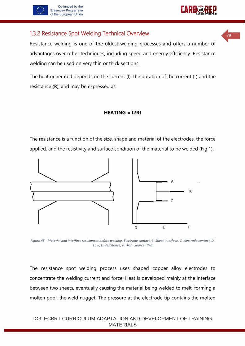
IO3: ECBRT CURRICULUM ADAPTATION AND DEVELOPMENT OF TRAINING
MATERIALS
79
1.3.2 Resistance Spot Welding Technical Overview
Resistance welding is one of the oldest welding processes and offers a number of
advantages over other techniques, including speed and energy efficiency. Resistance
welding can be used on very thin or thick sections.
The heat generated depends on the current (I), the duration of the current (t) and the
resistance (R), and may be expressed as:
HEATING = l2Rt
The resistance is a function of the size, shape and material of the electrodes, the force
applied, and the resistivity and surface condition of the material to be welded (Fig.1).
Figure 45 - Material and interface resistances before welding. Electrode contact, B. Sheet interface, C. electrode contact, D. Low, E. Resistance, F. High. Source: TWI
The resistance spot welding process uses shaped copper alloy electrodes to
concentrate the welding current and force. Heat is developed mainly at the interface
between two sheets, eventually causing the material being welded to melt, forming a
molten pool, the weld nugget. The pressure at the electrode tip contains the molten
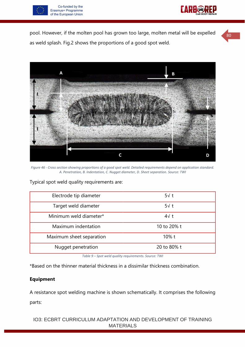
IO3: ECBRT CURRICULUM ADAPTATION AND DEVELOPMENT OF TRAINING
MATERIALS
80
pool. However, if the molten pool has grown too large, molten metal will be expelled
as weld splash. Fig.2 shows the proportions of a good spot weld.
Figure 46 - Cross section showing proportions of a good spot weld. Detailed requirements depend on application standard. A. Penetration, B. Indentation, C. Nugget diameter, D. Sheet separation. Source: TWI
Typical spot weld quality requirements are:
Electrode tip diameter 5√ t
Target weld diameter 5√ t
Minimum weld diameter* 4√ t
Maximum indentation 10 to 20% t
Maximum sheet separation 10% t
Nugget penetration 20 to 80% t
Table 9 – Spot weld quality requirements. Source: TWI
*Based on the thinner material thickness in a dissimilar thickness combination.
Equipment
A resistance spot welding machine is shown schematically. It comprises the following
parts:
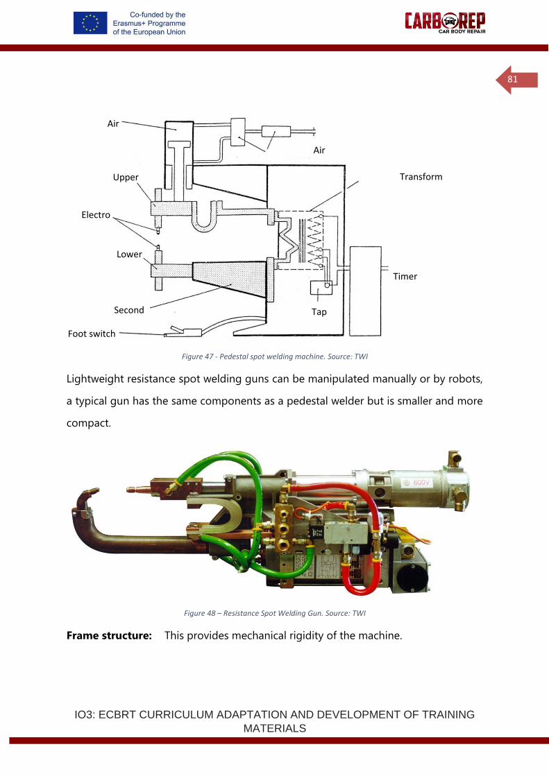
IO3: ECBRT CURRICULUM ADAPTATION AND DEVELOPMENT OF TRAINING
MATERIALS
81
Figure 47 - Pedestal spot welding machine. Source: TWI
Lightweight resistance spot welding guns can be manipulated manually or by robots,
a typical gun has the same components as a pedestal welder but is smaller and more
compact.
Figure 48 – Resistance Spot Welding Gun. Source: TWI
Frame structure: This provides mechanical rigidity of the machine.
Air
cylinder
Transform
er
Lower
arm
(fixed)
Upper
arm
(moveabl
e)
Electro
des
Air
control
s
Foot switch
Tap
switch
Timer
Second
ary
circuit
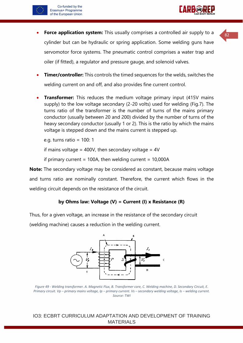
IO3: ECBRT CURRICULUM ADAPTATION AND DEVELOPMENT OF TRAINING
MATERIALS
82
• Force application system: This usually comprises a controlled air supply to a
cylinder but can be hydraulic or spring application. Some welding guns have
servomotor force systems. The pneumatic control comprises a water trap and
oiler (if fitted), a regulator and pressure gauge, and solenoid valves.
• Timer/controller: This controls the timed sequences for the welds, switches the
welding current on and off, and also provides fine current control.
• Transformer: This reduces the medium voltage primary input (415V mains
supply) to the low voltage secondary (2-20 volts) used for welding (Fig.7). The
turns ratio of the transformer is the number of turns of the mains primary
conductor (usually between 20 and 200) divided by the number of turns of the
heavy secondary conductor (usually 1 or 2). This is the ratio by which the mains
voltage is stepped down and the mains current is stepped up.
e.g. turns ratio = 100: 1
if mains voltage = 400V, then secondary voltage = 4V
if primary current = 100A, then welding current = 10,000A
Note: The secondary voltage may be considered as constant, because mains voltage
and turns ratio are nominally constant. Therefore, the current which flows in the
welding circuit depends on the resistance of the circuit.
by Ohms law: Voltage (V) = Current (I) x Resistance (R)
Thus, for a given voltage, an increase in the resistance of the secondary circuit
(welding machine) causes a reduction in the welding current.
Figure 49 - Welding transformer. A. Magnetic Flux, B. Transformer core, C. Welding machine, D. Secondary Circuit, E. Primary circuit. Vp – primary mains voltage, Ip – primary current. Vs – secondary welding voltage, Is – welding current.
Source: TWI
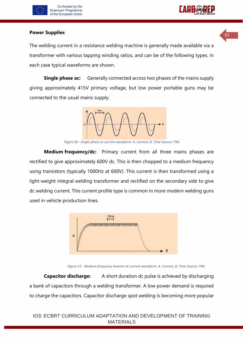
IO3: ECBRT CURRICULUM ADAPTATION AND DEVELOPMENT OF TRAINING
MATERIALS
83
Power Supplies
The welding current in a resistance welding machine is generally made available via a
transformer with various tapping winding ratios, and can be of the following types. In
each case typical waveforms are shown.
Single phase ac: Generally connected across two phases of the mains supply
giving approximately 415V primary voltage, but low power portable guns may be
connected to the usual mains supply.
Figure 50 - Single phase ac current waveform. A. Current, B. Time Source: TWI
Medium frequency/dc: Primary current from all three mains phases are
rectified to give approximately 600V dc. This is then chopped to a medium frequency
using transistors (typically 1000Hz at 600V). This current is then transformed using a
light-weight integral welding transformer and rectified on the secondary side to give
dc welding current. This current profile type is common in more modern welding guns
used in vehicle production lines.
Figure 51 - Medium frequency inverter dc current waveform. A. Current, B. Time Source: TWI
Capacitor discharge: A short duration dc pulse is achieved by discharging
a bank of capacitors through a welding transformer. A low power demand is required
to charge the capacitors. Capacitor discharge spot welding is becoming more popular
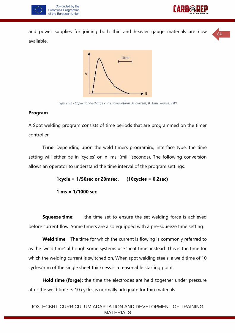
IO3: ECBRT CURRICULUM ADAPTATION AND DEVELOPMENT OF TRAINING
MATERIALS
84
and power supplies for joining both thin and heavier gauge materials are now
available.
Figure 52 - Capacitor discharge current waveform. A. Current, B. Time Source: TWI
Program
A Spot welding program consists of time periods that are programmed on the timer
controller.
Time: Depending upon the weld timers programing interface type, the time
setting will either be in ‘cycles’ or in ‘ms’ (milli seconds). The following conversion
allows an operator to understand the time interval of the program settings.
1cycle = 1/50sec or 20msec. (10cycles = 0.2sec)
1 ms = 1/1000 sec
Squeeze time: the time set to ensure the set welding force is achieved
before current flow. Some timers are also equipped with a pre-squeeze time setting.
Weld time: The time for which the current is flowing is commonly referred to
as the ‘weld time’ although some systems use ‘heat time’ instead. This is the time for
which the welding current is switched on. When spot welding steels, a weld time of 10
cycles/mm of the single sheet thickness is a reasonable starting point.
Hold time (forge): the time the electrodes are held together under pressure
after the weld time. 5-10 cycles is normally adequate for thin materials.

IO3: ECBRT CURRICULUM ADAPTATION AND DEVELOPMENT OF TRAINING
MATERIALS
85
Cool time: the current off time between successive current pulses in pulsation
welding or seam welding.
Off time: the time used for repeat welding such as stitch welding. The time
between the end of the hold time on one weld and the start of the squeeze time on
the next, during which the electrodes are re-positioned. This programming feature is
not commonly used in repair welding.
When using pulsed welding, the weld times may be set independently or the weld and
cool times alternate for the set number of pulses.
Figure 53 - Time and pressure diagram for spot welding showing two current pulses. A. Electrode position, B. electrode force, C. welding current, D. Squeeze time, E. Weld time 1, F. Cool time, G. Weld time 2, H. Hold time, I. Off time, J. Time.
Source: TWI
Electrode Force
Each material being welded will have its own optimum electrode force, depending on
the electrode tip size used for a particular sheet thickness.
The electrode force required for low carbon steel is normally
1.4 to 2.0kN per mm of the single sheet thickness
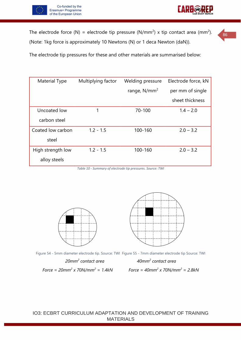
IO3: ECBRT CURRICULUM ADAPTATION AND DEVELOPMENT OF TRAINING
MATERIALS
86
The electrode force (N) = electrode tip pressure (N/mm2) x tip contact area (mm2).
(Note: 1kg force is approximately 10 Newtons (N) or 1 deca Newton (daN)).
The electrode tip pressures for these and other materials are summarised below:
Material Type Multiplying factor Welding pressure
range, N/mm2
Electrode force, kN
per mm of single
sheet thickness
Uncoated low
carbon steel
1 70-100 1.4 – 2.0
Coated low carbon
steel
1.2 - 1.5 100-160 2.0 – 3.2
High strength low
alloy steels
1.2 - 1.5 100-160 2.0 – 3.2
Table 10 - Summary of electrode tip pressures. Source: TWI
Figure 54 - 5mm diameter electrode tip. Source: TWI Figure 55 - 7mm diameter electrode tip Source: TWI
20mm2 contact area 40mm2 contact area
Force = 20mm2 x 70N/mm2 = 1.4kN Force = 40mm2 x 70N/mm2 = 2.8kN
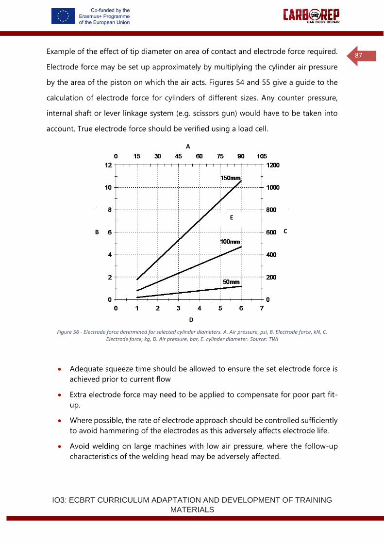
IO3: ECBRT CURRICULUM ADAPTATION AND DEVELOPMENT OF TRAINING
MATERIALS
87
Example of the effect of tip diameter on area of contact and electrode force required.
Electrode force may be set up approximately by multiplying the cylinder air pressure
by the area of the piston on which the air acts. Figures 54 and 55 give a guide to the
calculation of electrode force for cylinders of different sizes. Any counter pressure,
internal shaft or lever linkage system (e.g. scissors gun) would have to be taken into
account. True electrode force should be verified using a load cell.
Figure 56 - Electrode force determined for selected cylinder diameters. A. Air pressure, psi, B. Electrode force, kN, C. Electrode force, kg, D. Air pressure, bar, E. cylinder diameter. Source: TWI
• Adequate squeeze time should be allowed to ensure the set electrode force is
achieved prior to current flow
• Extra electrode force may need to be applied to compensate for poor part fit-
up.
• Where possible, the rate of electrode approach should be controlled sufficiently
to avoid hammering of the electrodes as this adversely affects electrode life.
• Avoid welding on large machines with low air pressure, where the follow-up
characteristics of the welding head may be adversely affected.
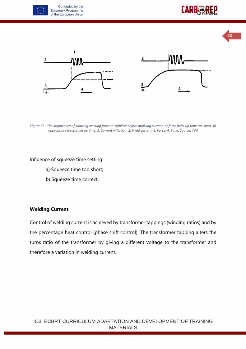
IO3: ECBRT CURRICULUM ADAPTATION AND DEVELOPMENT OF TRAINING
MATERIALS
88
Figure 57 - The importance of allowing welding force to stabilise before applying current. a) force build up time too short, b) appropriate force build up time. 1. Current initiation, 2. Weld current, 3. Force, 4. Time. Source: TWI
Influence of squeeze time setting:
a) Squeeze time too short;
b) Squeeze time correct.
Welding Current
Control of welding current is achieved by transformer tappings (winding ratios) and by
the percentage heat control (phase shift control). The transformer tapping alters the
turns ratio of the transformer by giving a different voltage to the transformer and
therefore a variation in welding current.
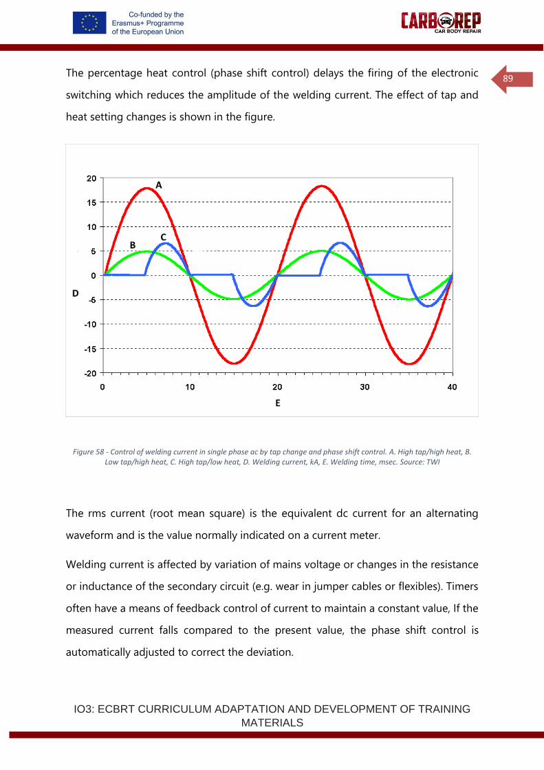
IO3: ECBRT CURRICULUM ADAPTATION AND DEVELOPMENT OF TRAINING
MATERIALS
89
The percentage heat control (phase shift control) delays the firing of the electronic
switching which reduces the amplitude of the welding current. The effect of tap and
heat setting changes is shown in the figure.
Figure 58 - Control of welding current in single phase ac by tap change and phase shift control. A. High tap/high heat, B. Low tap/high heat, C. High tap/low heat, D. Welding current, kA, E. Welding time, msec. Source: TWI
The rms current (root mean square) is the equivalent dc current for an alternating
waveform and is the value normally indicated on a current meter.
Welding current is affected by variation of mains voltage or changes in the resistance
or inductance of the secondary circuit (e.g. wear in jumper cables or flexibles). Timers
often have a means of feedback control of current to maintain a constant value, If the
measured current falls compared to the present value, the phase shift control is
automatically adjusted to correct the deviation.
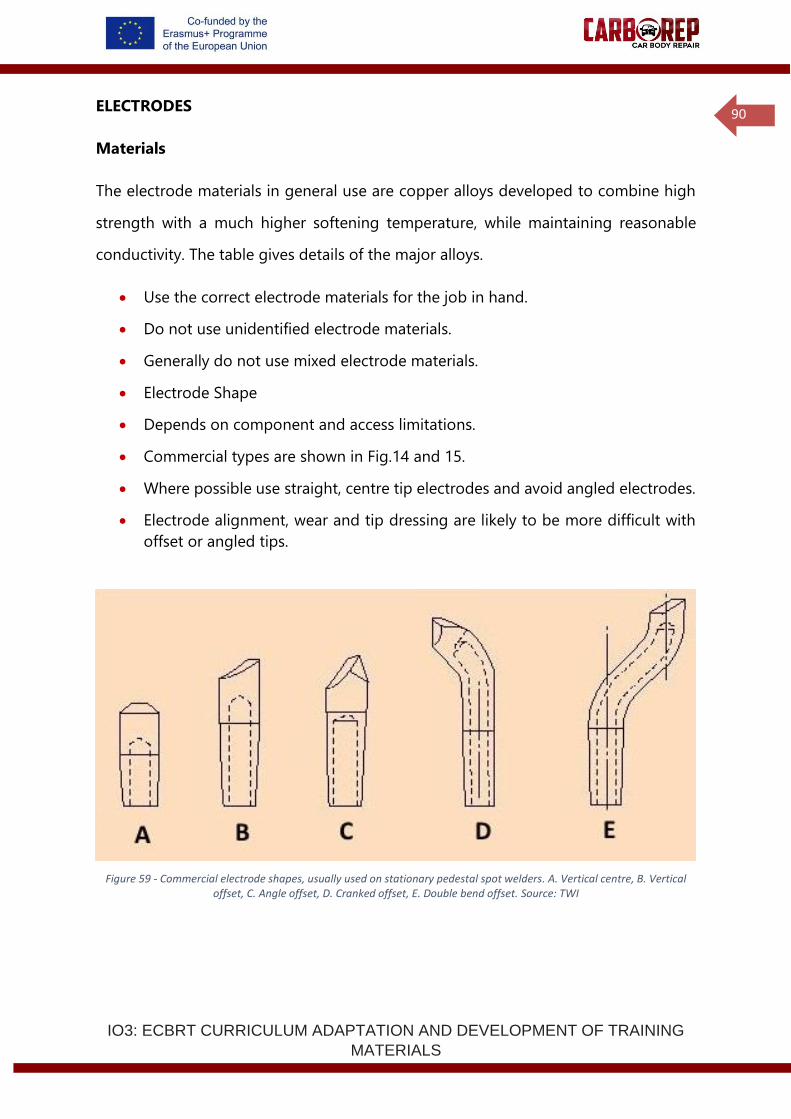
IO3: ECBRT CURRICULUM ADAPTATION AND DEVELOPMENT OF TRAINING
MATERIALS
90
ELECTRODES
Materials
The electrode materials in general use are copper alloys developed to combine high
strength with a much higher softening temperature, while maintaining reasonable
conductivity. The table gives details of the major alloys.
• Use the correct electrode materials for the job in hand.
• Do not use unidentified electrode materials.
• Generally do not use mixed electrode materials.
• Electrode Shape
• Depends on component and access limitations.
• Commercial types are shown in Fig.14 and 15.
• Where possible use straight, centre tip electrodes and avoid angled electrodes.
• Electrode alignment, wear and tip dressing are likely to be more difficult with
offset or angled tips.
Figure 59 - Commercial electrode shapes, usually used on stationary pedestal spot welders. A. Vertical centre, B. Vertical offset, C. Angle offset, D. Cranked offset, E. Double bend offset. Source: TWI
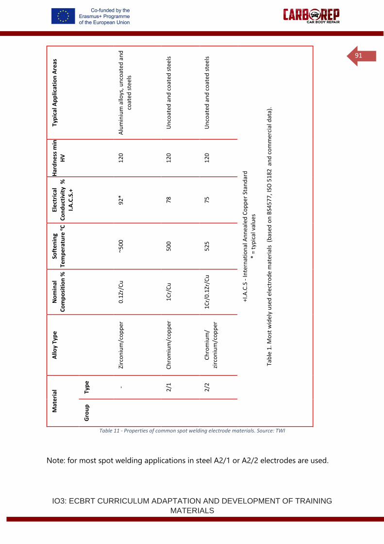
IO3: ECBRT CURRICULUM ADAPTATION AND DEVELOPMENT OF TRAINING
MATERIALS
91
Typ
ical
Ap
plic
atio
n A
reas
Alu
min
ium
allo
ys, u
nco
ated
an
d
coat
ed s
teel
s
Un
coat
ed a
nd
co
ated
ste
els
Un
coat
ed a
nd
co
ated
ste
els
+I.A
.C.S
- In
tern
atio
nal
An
nea
led
Co
pp
er S
tan
dar
d
* =
typ
ical
val
ue
s
Tab
le 1
. Mo
st w
ide
ly u
sed
ele
ctro
de
mat
eria
ls (
bas
ed o
n B
S45
77
, ISO
51
82
an
d c
om
mer
cial
dat
a).
Har
dn
ess
min
HV
12
0
12
0
12
0
Ele
ctri
cal
Co
nd
uct
ivit
y %
I.A
.C.S
.+
92
*
78
75
Soft
en
ing
Tem
pe
ratu
re o
C
~50
0
50
0
52
5
No
min
al
Co
mp
osi
tio
n %
0.1
Zr/C
u
1C
r/C
u
1C
r/0
.1Zr
/Cu
Allo
y Ty
pe
Zirc
on
ium
/co
pp
er
Ch
rom
ium
/co
pp
er
Ch
rom
ium
/
zirc
on
ium
/co
pp
er
Mat
eri
al
Typ
e
-
2/1
2/2
Gro
up
Table 11 - Properties of common spot welding electrode materials. Source: TWI
Note: for most spot welding applications in steel A2/1 or A2/2 electrodes are used.
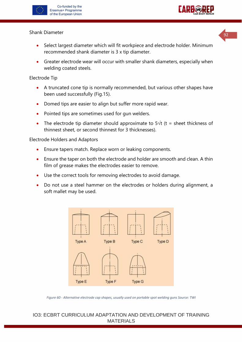
IO3: ECBRT CURRICULUM ADAPTATION AND DEVELOPMENT OF TRAINING
MATERIALS
92
Shank Diameter
• Select largest diameter which will fit workpiece and electrode holder. Minimum
recommended shank diameter is 3 x tip diameter.
• Greater electrode wear will occur with smaller shank diameters, especially when
welding coated steels.
Electrode Tip
• A truncated cone tip is normally recommended, but various other shapes have
been used successfully (Fig.15).
• Domed tips are easier to align but suffer more rapid wear.
• Pointed tips are sometimes used for gun welders.
• The electrode tip diameter should approximate to 5t (t = sheet thickness of
thinnest sheet, or second thinnest for 3 thicknesses).
Electrode Holders and Adaptors
• Ensure tapers match. Replace worn or leaking components.
• Ensure the taper on both the electrode and holder are smooth and clean. A thin
film of grease makes the electrodes easier to remove.
• Use the correct tools for removing electrodes to avoid damage.
• Do not use a steel hammer on the electrodes or holders during alignment, a
soft mallet may be used.
Figure 60 - Alternative electrode cap shapes, usually used on portable spot welding guns Source: TWI
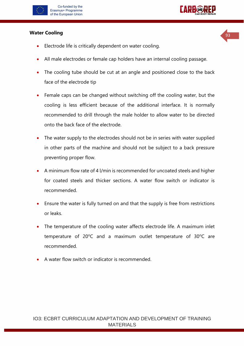
IO3: ECBRT CURRICULUM ADAPTATION AND DEVELOPMENT OF TRAINING
MATERIALS
93
Water Cooling
• Electrode life is critically dependent on water cooling.
• All male electrodes or female cap holders have an internal cooling passage.
• The cooling tube should be cut at an angle and positioned close to the back
face of the electrode tip
• Female caps can be changed without switching off the cooling water, but the
cooling is less efficient because of the additional interface. It is normally
recommended to drill through the male holder to allow water to be directed
onto the back face of the electrode.
• The water supply to the electrodes should not be in series with water supplied
in other parts of the machine and should not be subject to a back pressure
preventing proper flow.
• A minimum flow rate of 4 l/min is recommended for uncoated steels and higher
for coated steels and thicker sections. A water flow switch or indicator is
recommended.
• Ensure the water is fully turned on and that the supply is free from restrictions
or leaks.
• The temperature of the cooling water affects electrode life. A maximum inlet
temperature of 20oC and a maximum outlet temperature of 30oC are
recommended.
• A water flow switch or indicator is recommended.
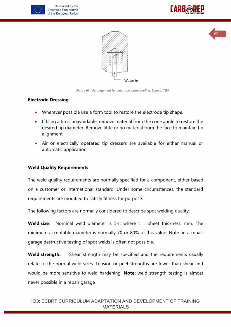
IO3: ECBRT CURRICULUM ADAPTATION AND DEVELOPMENT OF TRAINING
MATERIALS
94
Figure 61 - Arrangement for electrode water cooling. Source: TWI
Electrode Dressing
• Wherever possible use a form tool to restore the electrode tip shape.
• If filing a tip is unavoidable, remove material from the cone angle to restore the
desired tip diameter. Remove little or no material from the face to maintain tip
alignment.
• Air or electrically operated tip dressers are available for either manual or
automatic application.
Weld Quality Requirements
The weld quality requirements are normally specified for a component, either based
on a customer or international standard. Under some circumstances, the standard
requirements are modified to satisfy fitness for purpose.
The following factors are normally considered to describe spot welding quality:
Weld size: Nominal weld diameter is 5t where t = sheet thickness, mm. The
minimum acceptable diameter is normally 70 or 80% of this value. Note: in a repair
garage destructive testing of spot welds is often not possible.
Weld strength: Shear strength may be specified and the requirements usually
relate to the normal weld sizes. Tension or peel strengths are lower than shear and
would be more sensitive to weld hardening. Note: weld strength testing is almost
never possible in a repair garage
Water in
IO3: ECBRT CURRICULUM ADAPTATION AND DEVELOPMENT OF TRAINING
MATERIALS
95
Appearance: Excessive indentation, surface splash (weld spurs), edge damage
and surface burning or cracking are usually limited.
Metallographic: Nugget penetration, weld hardness, internal cracking and porosity
may have specified limits. Note: metallographic testing is almost never possible in a
repair garage.
Setting –up a spot welding process
In both automotive production and crash repair resistance spot welding is the primary
process for joining thin sheet steel. Resistance spot welding is a very fast and reliable
process that is readily automated and does not require much operator skill. The
greatest technical requirement of resistance spot welding is to ensure that the process
is correctly set-up in the first instance. A new resistance spot welding process will be
set-up to:
• Manufacture a component for the first time
• Manufacture an existing component from a new material combination
• Repair a component
Despite its apparent simplicity resistance spot welding is influenced by many local
variables, variation in welding machine characteristics and the influence of component
geometry and fit-up mean that no universal set of parameters can be applied to a
given material combination. Although many standards exist advising the range of
parameters that should usually be applied for specific materials.
When setting-up a new resistance spot welding process optimum parameters must be
sought (usually using a standard as a guideline) and the weld quality must be verified,
this is done by destructive testing.
Destructive (peel) testing
The main method for verification of spot weld quality is destructive testing, where-by
spot welds are torn apart by an externally applied force and the parent metal breaks
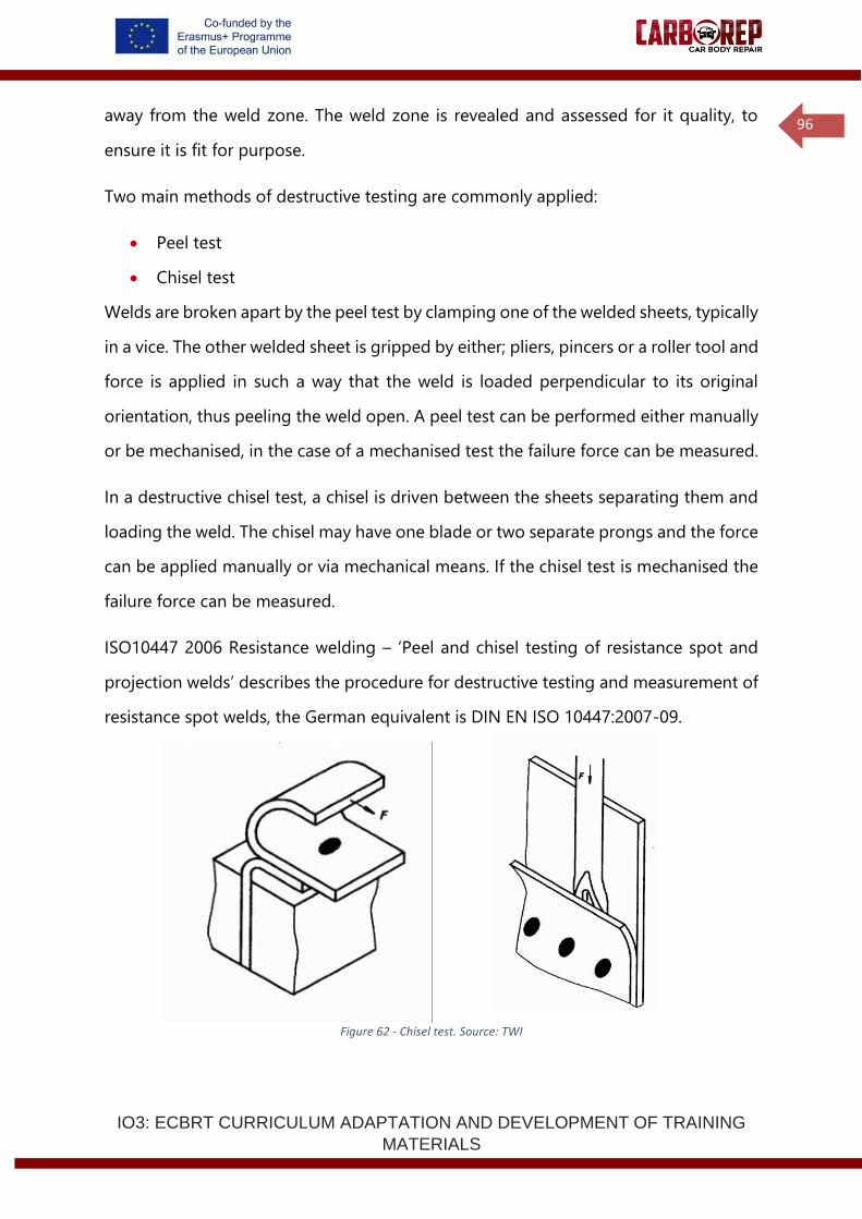
IO3: ECBRT CURRICULUM ADAPTATION AND DEVELOPMENT OF TRAINING
MATERIALS
96
away from the weld zone. The weld zone is revealed and assessed for it quality, to
ensure it is fit for purpose.
Two main methods of destructive testing are commonly applied:
• Peel test
• Chisel test
Welds are broken apart by the peel test by clamping one of the welded sheets, typically
in a vice. The other welded sheet is gripped by either; pliers, pincers or a roller tool and
force is applied in such a way that the weld is loaded perpendicular to its original
orientation, thus peeling the weld open. A peel test can be performed either manually
or be mechanised, in the case of a mechanised test the failure force can be measured.
In a destructive chisel test, a chisel is driven between the sheets separating them and
loading the weld. The chisel may have one blade or two separate prongs and the force
can be applied manually or via mechanical means. If the chisel test is mechanised the
failure force can be measured.
ISO10447 2006 Resistance welding – ‘Peel and chisel testing of resistance spot and
projection welds’ describes the procedure for destructive testing and measurement of
resistance spot welds, the German equivalent is DIN EN ISO 10447:2007-09.
Figure 62 - Chisel test. Source: TWI
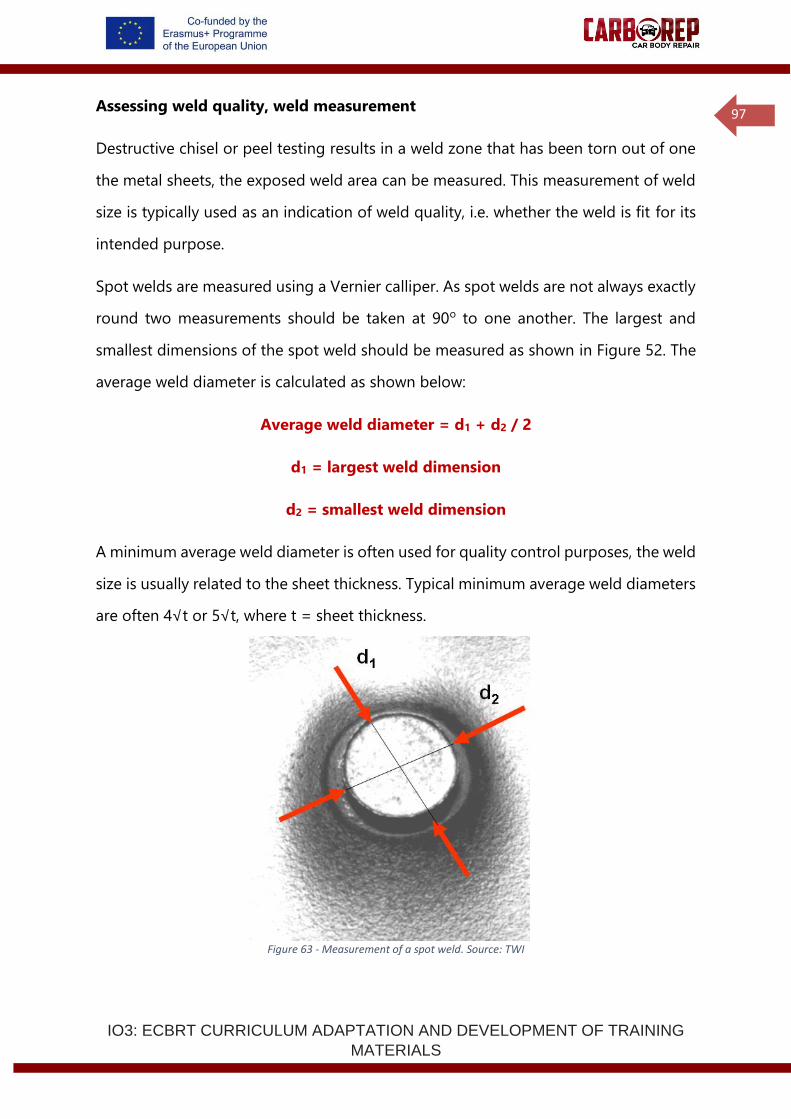
IO3: ECBRT CURRICULUM ADAPTATION AND DEVELOPMENT OF TRAINING
MATERIALS
97
Assessing weld quality, weld measurement
Destructive chisel or peel testing results in a weld zone that has been torn out of one
the metal sheets, the exposed weld area can be measured. This measurement of weld
size is typically used as an indication of weld quality, i.e. whether the weld is fit for its
intended purpose.
Spot welds are measured using a Vernier calliper. As spot welds are not always exactly
round two measurements should be taken at 90o to one another. The largest and
smallest dimensions of the spot weld should be measured as shown in Figure 52. The
average weld diameter is calculated as shown below:
Average weld diameter = d1 + d2 / 2
d1 = largest weld dimension
d2 = smallest weld dimension
A minimum average weld diameter is often used for quality control purposes, the weld
size is usually related to the sheet thickness. Typical minimum average weld diameters
are often 4√t or 5√t, where t = sheet thickness.
Figure 63 - Measurement of a spot weld. Source: TWI
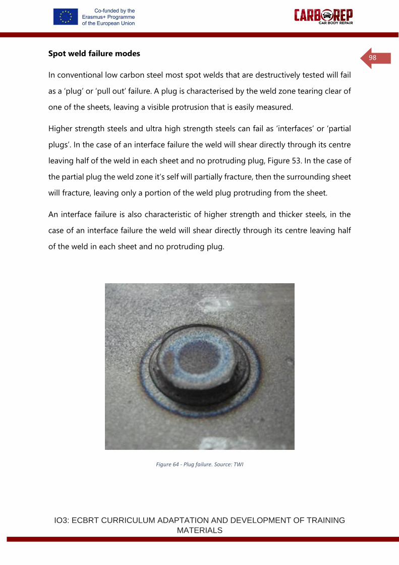
IO3: ECBRT CURRICULUM ADAPTATION AND DEVELOPMENT OF TRAINING
MATERIALS
98
Spot weld failure modes
In conventional low carbon steel most spot welds that are destructively tested will fail
as a ‘plug’ or ‘pull out’ failure. A plug is characterised by the weld zone tearing clear of
one of the sheets, leaving a visible protrusion that is easily measured.
Higher strength steels and ultra high strength steels can fail as ‘interfaces’ or ‘partial
plugs’. In the case of an interface failure the weld will shear directly through its centre
leaving half of the weld in each sheet and no protruding plug, Figure 53. In the case of
the partial plug the weld zone it’s self will partially fracture, then the surrounding sheet
will fracture, leaving only a portion of the weld plug protruding from the sheet.
An interface failure is also characteristic of higher strength and thicker steels, in the
case of an interface failure the weld will shear directly through its centre leaving half
of the weld in each sheet and no protruding plug.
Figure 64 - Plug failure. Source: TWI
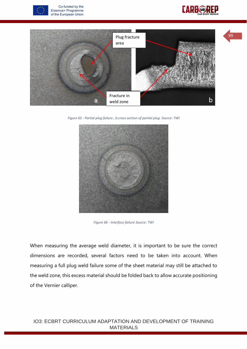
IO3: ECBRT CURRICULUM ADAPTATION AND DEVELOPMENT OF TRAINING
MATERIALS
99
Figure 65 - Partial plug failure , b:cross section of partial plug. Source: TWI
Figure 66 - Interface failure Source: TWI
When measuring the average weld diameter, it is important to be sure the correct
dimensions are recorded, several factors need to be taken into account. When
measuring a full plug weld failure some of the sheet material may still be attached to
the weld zone, this excess material should be folded back to allow accurate positioning
of the Vernier calliper.
Plug fracture
area
Fracture in
weld zone
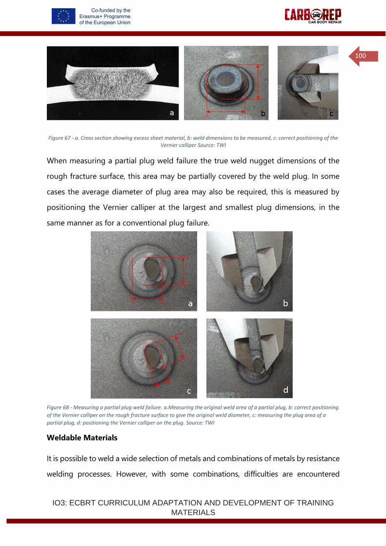
IO3: ECBRT CURRICULUM ADAPTATION AND DEVELOPMENT OF TRAINING
MATERIALS
100
Figure 67 - a. Cross section showing excess sheet material, b: weld dimensions to be measured, c: correct positioning of the Vernier calliper Source: TWI
When measuring a partial plug weld failure the true weld nugget dimensions of the
rough fracture surface, this area may be partially covered by the weld plug. In some
cases the average diameter of plug area may also be required, this is measured by
positioning the Vernier calliper at the largest and smallest plug dimensions, in the
same manner as for a conventional plug failure.
Figure 68 - Measuring a partial plug weld failure. a.Measuring the original weld area of a partial plug, b: correct positioning
of the Vernier calliper on the rough fracture surface to give the original weld diameter, c: measuring the plug area of a
partial plug, d: positioning the Vernier calliper on the plug. Source: TWI
Weldable Materials
It is possible to weld a wide selection of metals and combinations of metals by resistance
welding processes. However, with some combinations, difficulties are encountered
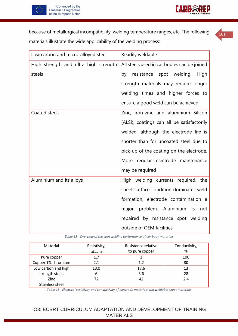
IO3: ECBRT CURRICULUM ADAPTATION AND DEVELOPMENT OF TRAINING
MATERIALS
101
because of metallurgical incompatibility, welding temperature ranges, etc. The following
materials illustrate the wide applicability of the welding process:
Low carbon and micro-alloyed steel Readily weldable
High strength and ultra high strength
steels
All steels used in car bodies can be joined
by resistance spot welding. High
strength materials may require longer
welding times and higher forces to
ensure a good weld can be achieved.
Coated steels Zinc, iron-zinc and aluminium Silicon
(ALSi), coatings can all be satisfactorily
welded, although the electrode life is
shorter than for uncoated steel due to
pick-up of the coating on the electrode.
More regular electrode maintenance
may be required
Aluminium and its alloys High welding currents required, the
sheet surface condition dominates weld
formation, electrode contamination a
major problem. Aluminium is not
repaired by resistance spot welding
outside of OEM facilities
Table 12 - Overview of the spot welding performance of car body materials
Material Resistivity,
cm
Resistance relative to pure copper
Conductivity, %
Pure copper Copper 1% chromium
1.7 2.1
1 1.2
100 80
Low carbon and high strength steels
Zinc Stainless steel
13.0 6
72
17.6 3.6 42
13 28 2.4
Table 13 - Electrical resistivity and conductivity of electrode materials and weldable sheet materials
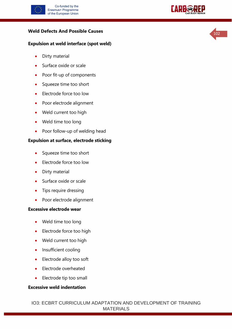
IO3: ECBRT CURRICULUM ADAPTATION AND DEVELOPMENT OF TRAINING
MATERIALS
102
Weld Defects And Possible Causes
Expulsion at weld interface (spot weld)
• Dirty material
• Surface oxide or scale
• Poor fit-up of components
• Squeeze time too short
• Electrode force too low
• Poor electrode alignment
• Weld current too high
• Weld time too long
• Poor follow-up of welding head
Expulsion at surface, electrode sticking
• Squeeze time too short
• Electrode force too low
• Dirty material
• Surface oxide or scale
• Tips require dressing
• Poor electrode alignment
Excessive electrode wear
• Weld time too long
• Electrode force too high
• Weld current too high
• Insufficient cooling
• Electrode alloy too soft
• Electrode overheated
• Electrode tip too small
Excessive weld indentation
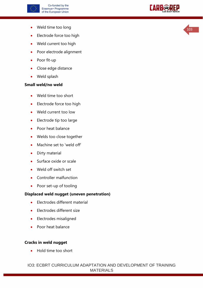
IO3: ECBRT CURRICULUM ADAPTATION AND DEVELOPMENT OF TRAINING
MATERIALS
103
• Weld time too long
• Electrode force too high
• Weld current too high
• Poor electrode alignment
• Poor fit-up
• Close edge distance
• Weld splash
Small weld/no weld
• Weld time too short
• Electrode force too high
• Weld current too low
• Electrode tip too large
• Poor heat balance
• Welds too close together
• Machine set to 'weld off'
• Dirty material
• Surface oxide or scale
• Weld off switch set
• Controller malfunction
• Poor set-up of tooling
Displaced weld nugget (uneven penetration)
• Electrodes different material
• Electrodes different size
• Electrodes misaligned
• Poor heat balance
Cracks in weld nugget
• Hold time too short

IO3: ECBRT CURRICULUM ADAPTATION AND DEVELOPMENT OF TRAINING
MATERIALS
104
• Electrode force too low
• Poor follow-up
• No (or incorrectly set) dual force/current decay (aluminium alloy)
1.3.3 Health and safety, and environmental safety
Working in a safe manner, to protect yourself, others and the vehicle or components
you are working on, is an essential consideration in any welding operation. The
responsibility for safety is on all individuals but especially the welding operator, not
only for their own safety, but also to avoid endangering other people. Your employer
has an important responsibility for ensuring that hea l th , safety and environment
(HSE) legislation is complied with and safe working practices are implemented. If you
cannot assure your own safety and the safety of others in the work area, then stop
welding and do not start welding again until the risk has been controlled.
Your employer should ensure compliance with all appropriate documents, for
example:
• Legislation – EU OSH Directives.
• Standards – OHSAS 18001.
• Company Health, Safety and Environment Management Systems.
• Work instructions – permits to work, risk assessment documents, etc.
The workshop environment
The employer needs to ensure that the lighting conditions are adequate for the work
undertaken - giving extra lighting where necessary.
Housekeeping is extremely important to avoid slips, trips and falls, damage to
equipment and fire.
There are many aspects of resistance welding safety that the welder needs to consider:
• Electric shock.
IO3: ECBRT CURRICULUM ADAPTATION AND DEVELOPMENT OF TRAINING
MATERIALS
105
• Electromagnetic Fields
• Heat
• Fumes and gases.
• Noise.
• Working at height or in restricted access.
• Mechanical hazards: trips, falls, cuts, impact from heavy objects.
Electric shock
Contact with metal parts that are electrically live can cause injury or death because
of the effect of the shock upon the body or because of a fall as a result of the reaction
to electric shock.
The electric shock hazard associated with resistance spot welding is minimal.
Although heat is generated with high current levels, the voltage used in welding is
typically in the region of 1 Volt, which is not sufficient to cause a shock. However, the
primary side of the transform operates at mains current. Only qualified electrical
personnel should work on the transformer primary side. Appropriate sage working
procedures must be followed.
It is important that the welding cables can carry the maximum possible output of
the welding set without overheating as overheating can damage the insulation,
leading to an increased risk of electrical shock.
Installation of welding equipment should be carried out by suitably qualified staff who
must check that the equipment is suitable for the operation and connected in
accordance with the manufacturer's recommendations. The welder is responsible for
checking the equipment (cables, welding guns, electrodes) daily for damage and
reporting defects. All external connections should be clean and tight and checked each
time a reconnection is made.
IO3: ECBRT CURRICULUM ADAPTATION AND DEVELOPMENT OF TRAINING
MATERIALS
106
Welder actions for safe practice and avoidance of electric shock:
• Do not wear jewellery (especially rings) or metallic watch straps
• Wear protective clothing safety boots, gloves, overalls, eye protection (goggles)
• When welding outside, check the power source protection rating is adequate
for the environment and do not weld in the rain without a suitable cover
• When welding the vehicle directly, ensure that the vehicle is electrically safe; a
competent auto electrician has isolated the batteries and any hybrid power
systems, and disconnected sensitive electronics units
Electromagnetic Fields
Welding processes may produce low frequency fields that have a detrimental effect on
the mental and physical health of the exposed workers. The possible effects include
stimulation of muscles, nerves or sensory organs and transitory symptoms such as
vertigo or retinal phosphenes. These effects may affect the ability of the worker to
work safely.
Electromagnetic fields may be sub-divided into magnetic and electric fields and for
most welding processes, it is the magnetic field which is significant.
Exposure to electromagnetic fields may cause direct biophysical effects, including:
• thermal effects such as tissue heating.
• non-thermal effects such as the stimulation of muscles, nerves or sensory
organs.
• Limb currents.
Indirect effects of EMF include:
• interference with medical electronic devices such as pacemakers.
• projectile risk from ferromagnetic objects in static magnetic fields.
• initiation of detonators.
• ignition of flammable materials by sparks caused by induced fields.
IO3: ECBRT CURRICULUM ADAPTATION AND DEVELOPMENT OF TRAINING
MATERIALS
107
• contact currents.
Welder actions for safe practice and avoidance of welding EMF:
• Follow the guidance from the employer’s workplace assessment
• Do not wrap welding cables around body
• Do not stand in coiled welding cables
Note: legal requirements for EMF may vary between countries within Europe
Heat
As resistance spot welding relies on melting metal to effect a joint, it follows that the
metal will in part be very hot. All metals conduct heat to a greater or lesser degree so
the area heated to a temperature that will cause skin burns is much larger than the
weld area itself.
The spot welding process can create sparks and spatter (liquid metal expulsion), with
the potential to cause flammable materials near the welding area to ignite and cause
fires. The welding area should be clear of all combustible materials and it is good
practice for all personnel working in the vicinity of welding to know where the nearest
fire extinguishers are and the correct type of fire extinguisher to use if a fire does break
out. Weld spatter can cause burns, so protective clothing, such as welding gloves,
flame retardant coveralls and leathers can offer protection to exposed skin.
Welder actions for safe practice and avoidance of effects of welding heat:
• Ensure that appropriate PPE is available, fit for use and correctly worn
• Ensure that combustible trim is removed from the vicinity of the joint and that
the car is protected, where necessary, with fire resistant blankets
IO3: ECBRT CURRICULUM ADAPTATION AND DEVELOPMENT OF TRAINING
MATERIALS
108
Fumes and gases
Fume is a mixture of particles generated by vaporisation, condensation and oxidation
of substances resulting from the welding heat. Fume particles are very small and may
remain suspended in the air for long periods, where they may be breathed.
Toxic fume may be created also from oils, paint finishes, coatings, adhesive bond lines
plastic materials in the vicinity of the welded joint.
The following aspects are likely to influence the degree to which the welder is exposed
to fume and gases:
• welding position
• location and type of workplace
Thus, welders using the same process may be exposed to different levels of fume. The
risks for each job should, therefore, be assessed individually.
On-gun extraction
In small volume spot welding fume extraction is not usually required. However, if the
materials welded produce heavy fume, extraction may be used. Local exhaust
ventilation (LEV) and on-gun (or work piece proximity) extraction systems are never
100% efficient, especially when welding awkward structures, general ventilation may
also be necessary to control the background level of fume.
As each type of extraction equipment has limitations, it is important to select the right
equipment for each job. It is also essential that welders are adequately trained to use
the equipment and adopt good working practices. Supervision is needed to ensure the
equipment is being used effectively and to minimise background fume level in the
workshop.
As a rule of thumb, if the air is visibly clear and the welder is comfortable, the
ventilation is probably adequate.
IO3: ECBRT CURRICULUM ADAPTATION AND DEVELOPMENT OF TRAINING
MATERIALS
109
Noise
Exposure to loud noise can permanently damage hearing, cause stress and increase
blood pressure. Working in a noisy environment for long periods can contribute to
tiredness, nervousness and irritability. If the noise exposure is greater than 85 A-
weighted decibels, averaged over an eight hour period then hearing protection must
be worn and annual hearing tests carried out. The employer has the responsibility of
ensuring that workers wear the protection.
Normal resistance welding operations are not associated with excessive noise level
problems. The noise associated with welding is usually due to ancillary operations such
as chipping, grinding and hammering. Hearing protection must be worn when carrying
out, or when working in the vicinity of, these operations.
Mechanical hazards
The environment in which a welder works has a number of hazards not specific to the
welding process itself. Manual handling of heavy awkward metal components is often
required. Thinner, lighter metal sheet may have sharp edges. Slips, trips and falls may
be more likely as welding often requires thick cables to be spread across the floor.
Standard workshop safety and protection practice should be used to counter these
problems. Welders need training in materials handling, both manual and with
mechanical lifting assistance; protective gloves, helmets, overalls and boots must be
worn; cabling on the floor should be minimised and clearly signed or marked as a trip
hazard.
There are hazards that are a direct result of the joining process, as during welding,
sparks and molten metal can be ejected. These are most common in arc welding but
can also occur in resistance processes. Personal protective equipment (PPE) must be
worn by the welder. All clothing should be fire resistant and use of leather aprons,
jackets, chaps, etc is recommended.
IO3: ECBRT CURRICULUM ADAPTATION AND DEVELOPMENT OF TRAINING
MATERIALS
110
Grinding is commonly used in preparing metal for welding and during cleaning and
rectification of deposited metal. Wheel and angle grinders are favorite tools for their
speed of removal of material. These create a hazard, not only for the operator but for
adjacent and passing personnel, as the ejected material may be thrown some distance.
Obviously the operator needs adequate protection with clothing, gloves, full-face
shields and sometimes a dust mask but the whole area also needs screening with
curtains to protect others. Fireproof blankets may be used to protect the vehicle from
grinding sparks, and care needs to be taken to prevent cross contamination between
vehicles and materials in the workshop.
One of the more serious dangers is from the persistent use of hand-held portable
power tools, such as grinders, sanders, impact wrenches, and air chisels, which can lead
to long-term illness – hand-arm vibration syndrome, also known as ‘white finger’ or
‘dead hand’. Employers are encouraged to purchase only power tools designed and
constructed to reduce the risk of vibration, and are required to conduct an assessment
and identify measures to eliminate or reduce the risk. You are required to use these
power tools only as instructed, and you should report any symptoms, including
tingling and numbness in fingers, not being able to feel things properly, loss of
strength in hands, fingertips going white, and becoming red and painful on recovery.
Entrapment of body parts of clothing between spot welding electrodes is the main
mechanical hazard of resistance spot welding. Ensure that operators and assistants
hands and clothing are not in the proximity of the electrodes during closure, as forces
greater than 1000N (100kg) are regularly employed, entrapment can result in very
severe injury.
IO3: ECBRT CURRICULUM ADAPTATION AND DEVELOPMENT OF TRAINING
MATERIALS
111
In the workshop
Checklist for setting up equipment
Quality Requirements:
• First establish what weld size (minimum diameter) and any other quality
requirements are needed for the material and thickness combination being
joined.
• Refer to customer standard, in-house standard or national standards, whichever
takes precedence.
• Equipment:
• Ensure suitable equipment is chosen to allow the required weld settings to be
achieved within the capacity of the machine.
• Ensure that the machine and timer are working correctly and that water cooling
is adequate.
• Ensure that any tooling is properly insulated and does not interfere with
pressure application or current flow.
Materials:
• Check that the materials meet the required specification.
• Ensure surfaces are free from contamination, rust, paint, etc.
• Make sure that the part fit-up, flange width and edge distance are satisfactory.
Electrodes:
• Decide what tip diameter is required to achieve the target weld size (minimum
weld size is usually 70-80% of this value).
• Choose the correct electrode material for the job and an electrode design to
suit the access to the part, using electrodes (caps) and holders with an adequate
shank diameter.
• Machine or dress electrodes to the required size and ensure electrode
alignment is accurate under load on the welding machine.
o If the electrode condition deteriorates during the job, repair the electrodes with
a tip dresser or replace them.
IO3: ECBRT CURRICULUM ADAPTATION AND DEVELOPMENT OF TRAINING
MATERIALS
112
Electrode Force:
• Select the force required which is appropriate for the materials being welded
and the electrode tip size being used. Recommended conditions are available.
Inappropriate settings can affect weldability and quality.
• Set up force required using a load cell and record the air pressure required to
achieve this force.
Weld parameter settings:
• Set up time sequence.
• Squeeze time should be adjusted using a squeeze analyser or initially set long
to ensure force is fully achieved before current flow.
• Weld time should be selected according to recommended conditions.
• Hold time is less critical, 5-10 cycles is normally suitable for thin materials e.g.
up to 1.5mm thick, and longer for thicker material or where fit-up is poor.
Welding Current:
• Perform test welds on spare material.
o Make welds at increasing levels of current until the required weld quality is
achieved on peel or chisel testing.
• A setting just below that giving weld splash generally gives the best welding
tolerance.
Set-up Records:
• It is good practice to record the final set-up conditions used on a job or process
sheet.

IO3: ECBRT CURRICULUM ADAPTATION AND DEVELOPMENT OF TRAINING
MATERIALS
113
Setting up the workshop for resistance spot welding:
Documentation: Which documents do you need to have before commencing
welding?
Health, safety and environment documents:
.............................................................................................................................................................................
...............................................................................................................
Welding standards or quality acceptance documents:
.............................................................................................................................................................................
...............................................................................................................
Personal Protective Equipment: List the PPE you must use and perform their pre-use
inspection.
.............................................................................................................................................................................
...............................................................................................................
Ventilation and extraction equipment (if required): Perform the pre-use inspection,
position and operate the equipment.
Notes
Resistance spot welding equipment: Perform the pre-use inspection, check
maintenance and calibration records, install the consumable electrodes.
Notes:
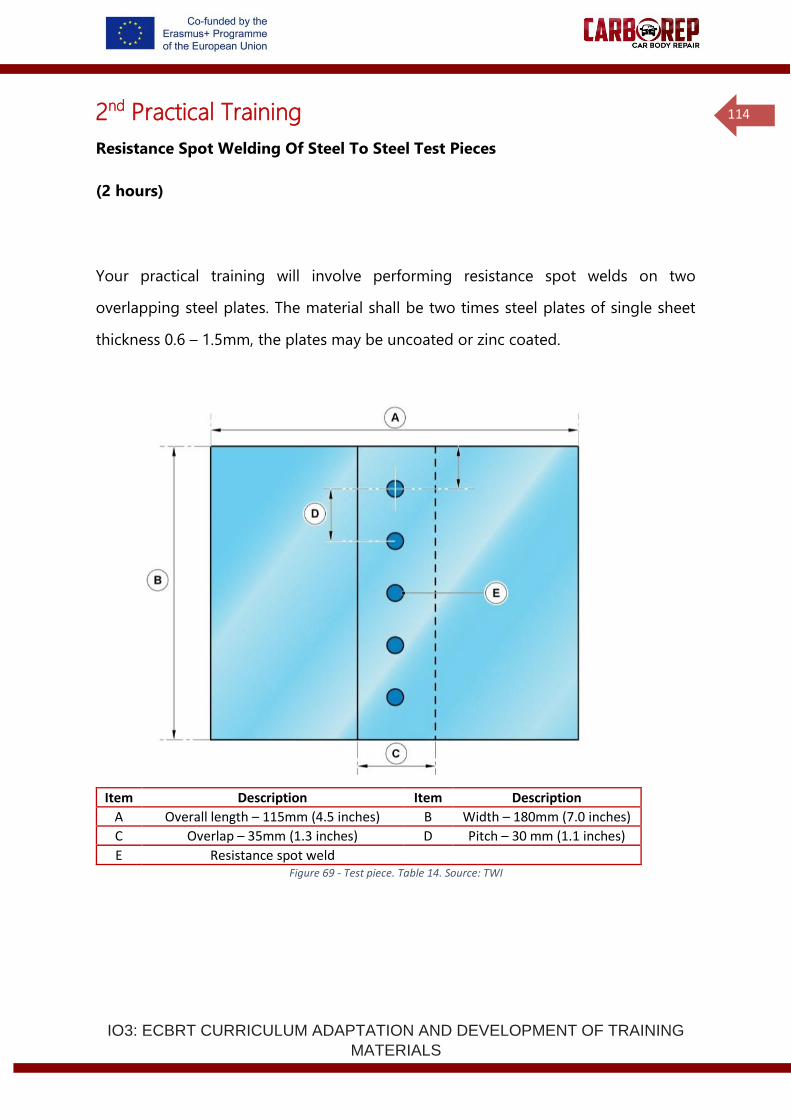
IO3: ECBRT CURRICULUM ADAPTATION AND DEVELOPMENT OF TRAINING
MATERIALS
114
2nd Practical Training
Resistance Spot Welding Of Steel To Steel Test Pieces
(2 hours)
Your practical training will involve performing resistance spot welds on two
overlapping steel plates. The material shall be two times steel plates of single sheet
thickness 0.6 – 1.5mm, the plates may be uncoated or zinc coated.
Item Description Item Description
A Overall length – 115mm (4.5 inches) B Width – 180mm (7.0 inches)
C Overlap – 35mm (1.3 inches) D Pitch – 30 mm (1.1 inches)
E Resistance spot weld Figure 69 - Test piece. Table 14. Source: TWI
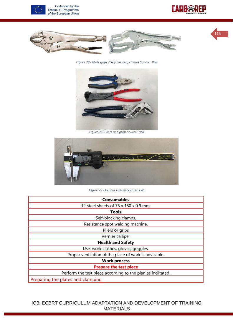
IO3: ECBRT CURRICULUM ADAPTATION AND DEVELOPMENT OF TRAINING
MATERIALS
115
Figure 70 - Mole grips / Self-blocking clamps Source: TWI
Figure 71 -Pliers and grips Source: TWI
Figure 72 - Vernier calliper Source: TWI
Consumables
12 steel sheets of 75 x 180 x 0.9 mm.
Tools
Self-blocking clamps.
Resistance spot welding machine.
Pliers or grips
Vernier calliper
Health and Safety
Use: work clothes, gloves, goggles.
Proper ventilation of the place of work is advisable.
Work process
Prepare the test piece
Perform the test piece according to the plan as indicated.
Preparing the plates and clamping
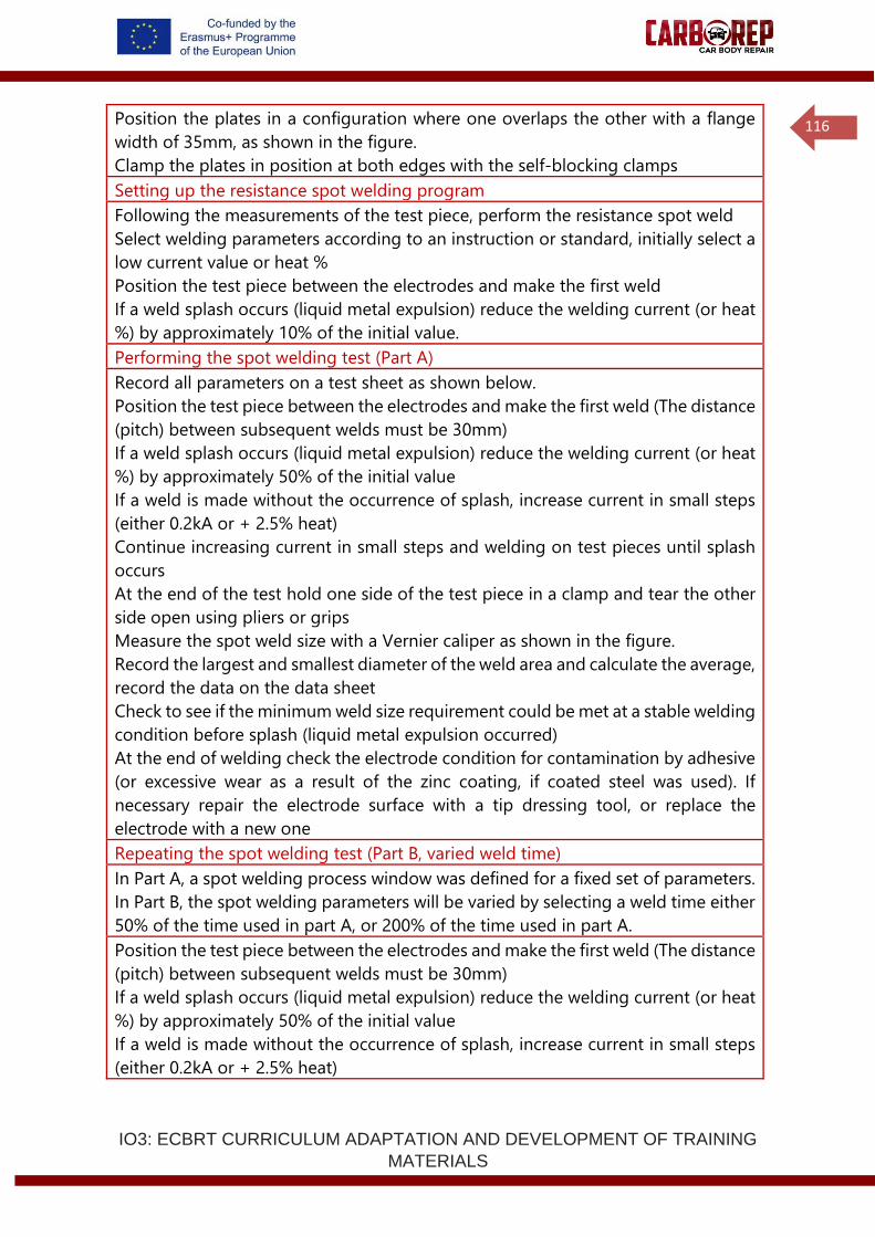
IO3: ECBRT CURRICULUM ADAPTATION AND DEVELOPMENT OF TRAINING
MATERIALS
116
Position the plates in a configuration where one overlaps the other with a flange
width of 35mm, as shown in the figure.
Clamp the plates in position at both edges with the self-blocking clamps
Setting up the resistance spot welding program
Following the measurements of the test piece, perform the resistance spot weld
Select welding parameters according to an instruction or standard, initially select a
low current value or heat %
Position the test piece between the electrodes and make the first weld
If a weld splash occurs (liquid metal expulsion) reduce the welding current (or heat
%) by approximately 10% of the initial value.
Performing the spot welding test (Part A)
Record all parameters on a test sheet as shown below.
Position the test piece between the electrodes and make the first weld (The distance
(pitch) between subsequent welds must be 30mm)
If a weld splash occurs (liquid metal expulsion) reduce the welding current (or heat
%) by approximately 50% of the initial value
If a weld is made without the occurrence of splash, increase current in small steps
(either 0.2kA or + 2.5% heat)
Continue increasing current in small steps and welding on test pieces until splash
occurs
At the end of the test hold one side of the test piece in a clamp and tear the other
side open using pliers or grips
Measure the spot weld size with a Vernier caliper as shown in the figure.
Record the largest and smallest diameter of the weld area and calculate the average,
record the data on the data sheet
Check to see if the minimum weld size requirement could be met at a stable welding
condition before splash (liquid metal expulsion occurred)
At the end of welding check the electrode condition for contamination by adhesive
(or excessive wear as a result of the zinc coating, if coated steel was used). If
necessary repair the electrode surface with a tip dressing tool, or replace the
electrode with a new one
Repeating the spot welding test (Part B, varied weld time)
In Part A, a spot welding process window was defined for a fixed set of parameters.
In Part B, the spot welding parameters will be varied by selecting a weld time either
50% of the time used in part A, or 200% of the time used in part A.
Position the test piece between the electrodes and make the first weld (The distance
(pitch) between subsequent welds must be 30mm)
If a weld splash occurs (liquid metal expulsion) reduce the welding current (or heat
%) by approximately 50% of the initial value
If a weld is made without the occurrence of splash, increase current in small steps
(either 0.2kA or + 2.5% heat)
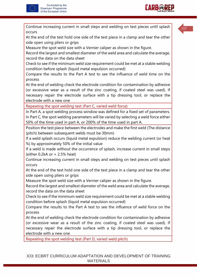
IO3: ECBRT CURRICULUM ADAPTATION AND DEVELOPMENT OF TRAINING
MATERIALS
117
Continue increasing current in small steps and welding on test pieces until splash
occurs
At the end of the test hold one side of the test piece in a clamp and tear the other
side open using pliers or grips
Measure the spot weld size with a Vernier caliper as shown in the figure.
Record the largest and smallest diameter of the weld area and calculate the average,
record the data on the data sheet
Check to see if the minimum weld size requirement could be met at a stable welding
condition before splash (liquid metal expulsion occurred)
Compare the results to the Part A test to see the influence of weld time on the
process
At the end of welding check the electrode condition for contamination by adhesive
(or excessive wear as a result of the zinc coating, if coated steel was used). If
necessary repair the electrode surface with a tip dressing tool, or replace the
electrode with a new one
Repeating the spot welding test (Part C, varied weld force)
In Part A, a spot welding process window was defined for a fixed set of parameters.
In Part C, the spot welding parameters will be varied by selecting a weld force either
50% of the time used in part A, or 200% of the time used in part A.
Position the test piece between the electrodes and make the first weld (The distance
(pitch) between subsequent welds must be 30mm)
If a weld splash occurs (liquid metal expulsion) reduce the welding current (or heat
%) by approximately 50% of the initial value
If a weld is made without the occurrence of splash, increase current in small steps
(either 0.2kA or + 2.5% heat)
Continue increasing current in small steps and welding on test pieces until splash
occurs
At the end of the test hold one side of the test piece in a clamp and tear the other
side open using pliers or grips
Measure the spot weld size with a Vernier caliper as shown in the figure.
Record the largest and smallest diameter of the weld area and calculate the average,
record the data on the data sheet
Check to see if the minimum weld size requirement could be met at a stable welding
condition before splash (liquid metal expulsion occurred)
Compare the results to the Part A test to see the influence of weld force on the
process
At the end of welding check the electrode condition for contamination by adhesive
(or excessive wear as a result of the zinc coating, if coated steel was used). If
necessary repair the electrode surface with a tip dressing tool, or replace the
electrode with a new one
Repeating the spot welding test (Part D, varied weld pitch)
IO3: ECBRT CURRICULUM ADAPTATION AND DEVELOPMENT OF TRAINING
MATERIALS
118
In Part D, the spot welding pitch (distance between welds) shall be varied to see the
effect on the weld quality
Select preferred welding parameters from Part A, B or C
Manufacture an initial spot weld
Manufacture the second weld at a pitch of 30mm
Manufacture the 3rd weld at a pitch of 60mm
Manufacture the 4th weld at a pitch of 10mm
At the end of the test hold one side of the test piece in a clamp and tear the other
side open using pliers or grips
Measure the spot weld size with a Vernier caliper as shown in the figure.
Record the largest and smallest diameter of the weld area and calculate the average,
record the data on the data sheet
Compare the results to the previous tests to see the influence of weld pitch on the
weld quality
At the end of welding check the electrode condition for contamination by adhesive
(or excessive wear as a result of the zinc coating, if coated steel was used). If
necessary repair the electrode surface with a tip dressing tool, or replace the
electrode with a new one
Example spot welding data sheet
Operator Name:
Date:
Welding machine:
Standards / procedures followed:
Vehicle / component:
Material 1:
Material 2:
Material 3:
Electrode details
Water cooling
Test piece dimensions:
Weld pitch:
Adhesive used:
Adhesive expiry date:
Squeeze time:
Weld time:
Hold time:
Electrode force / pressure:
Transformer tap:
Weld
number
Current
(kA or
heat %)
Weld
diameter
d1 (mm)
Weld
diameter
d2 (mm)
Average
diameter
d1+d2/2 (mm)
Weld
splash
(expulsion)
Comments
observations
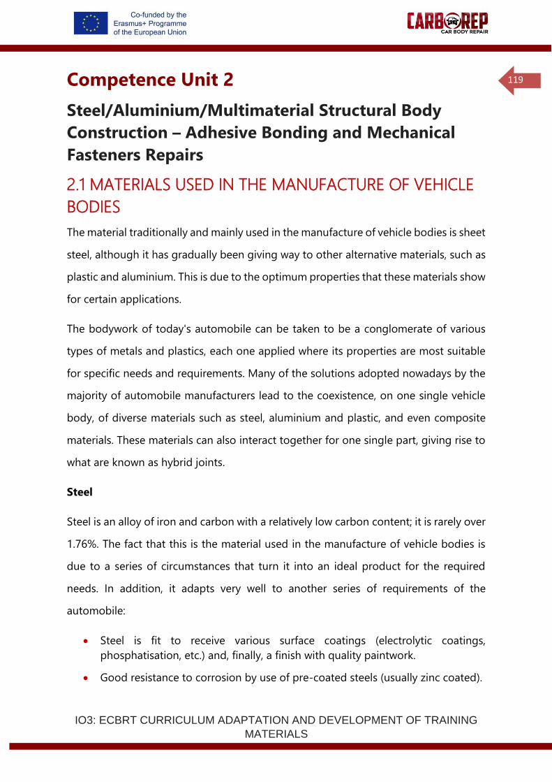
IO3: ECBRT CURRICULUM ADAPTATION AND DEVELOPMENT OF TRAINING
MATERIALS
119
Competence Unit 2
Steel/Aluminium/Multimaterial Structural Body
Construction – Adhesive Bonding and Mechanical
Fasteners Repairs
2.1 MATERIALS USED IN THE MANUFACTURE OF VEHICLE
BODIES
The material traditionally and mainly used in the manufacture of vehicle bodies is sheet
steel, although it has gradually been giving way to other alternative materials, such as
plastic and aluminium. This is due to the optimum properties that these materials show
for certain applications.
The bodywork of today's automobile can be taken to be a conglomerate of various
types of metals and plastics, each one applied where its properties are most suitable
for specific needs and requirements. Many of the solutions adopted nowadays by the
majority of automobile manufacturers lead to the coexistence, on one single vehicle
body, of diverse materials such as steel, aluminium and plastic, and even composite
materials. These materials can also interact together for one single part, giving rise to
what are known as hybrid joints.
Steel
Steel is an alloy of iron and carbon with a relatively low carbon content; it is rarely over
1.76%. The fact that this is the material used in the manufacture of vehicle bodies is
due to a series of circumstances that turn it into an ideal product for the required
needs. In addition, it adapts very well to another series of requirements of the
automobile:
• Steel is fit to receive various surface coatings (electrolytic coatings,
phosphatisation, etc.) and, finally, a finish with quality paintwork.
• Good resistance to corrosion by use of pre-coated steels (usually zinc coated).
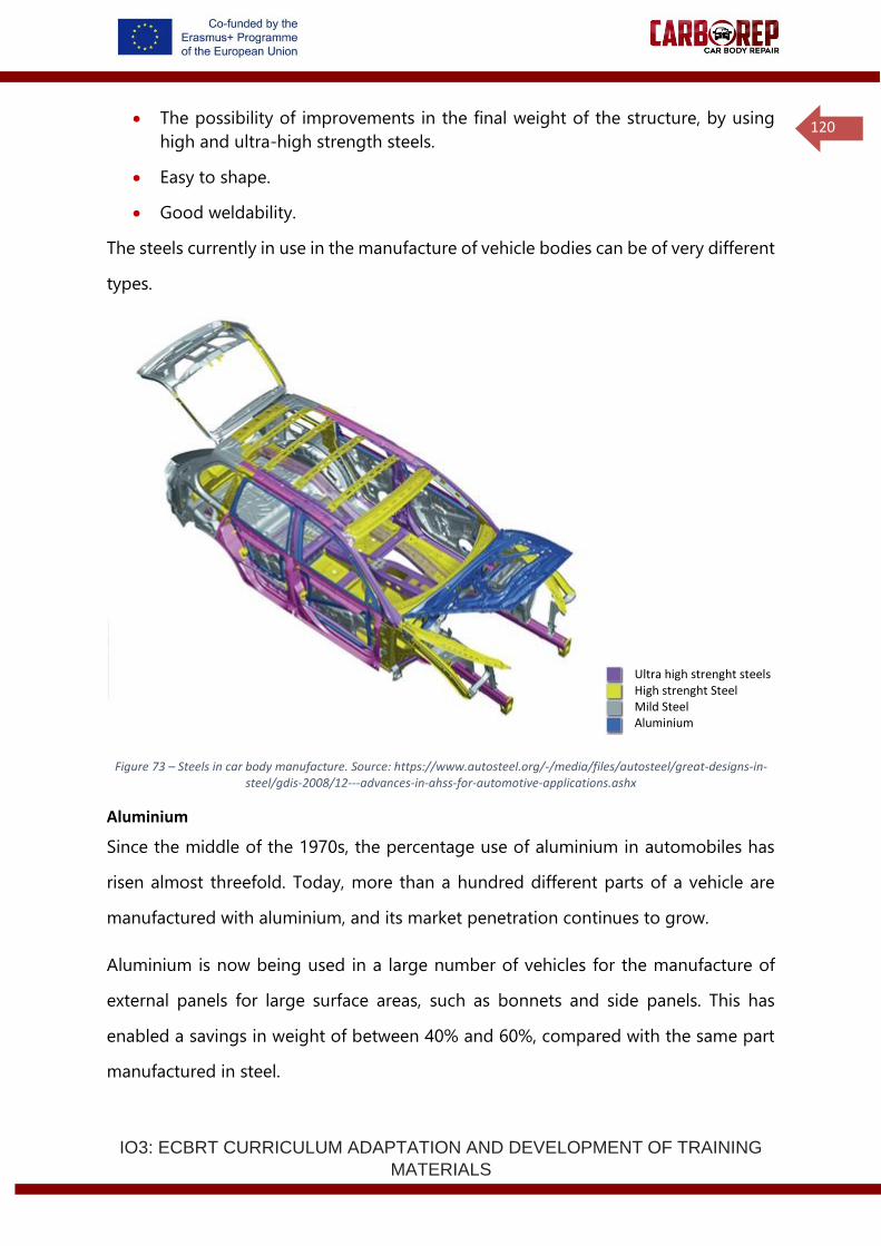
IO3: ECBRT CURRICULUM ADAPTATION AND DEVELOPMENT OF TRAINING
MATERIALS
120
• The possibility of improvements in the final weight of the structure, by using
high and ultra-high strength steels.
• Easy to shape.
• Good weldability.
The steels currently in use in the manufacture of vehicle bodies can be of very different
types.
Figure 73 – Steels in car body manufacture. Source: https://www.autosteel.org/-/media/files/autosteel/great-designs-in-steel/gdis-2008/12---advances-in-ahss-for-automotive-applications.ashx
Aluminium
Since the middle of the 1970s, the percentage use of aluminium in automobiles has
risen almost threefold. Today, more than a hundred different parts of a vehicle are
manufactured with aluminium, and its market penetration continues to grow.
Aluminium is now being used in a large number of vehicles for the manufacture of
external panels for large surface areas, such as bonnets and side panels. This has
enabled a savings in weight of between 40% and 60%, compared with the same part
manufactured in steel.
Ultra high strenght steels High strenght Steel Mild Steel Aluminium
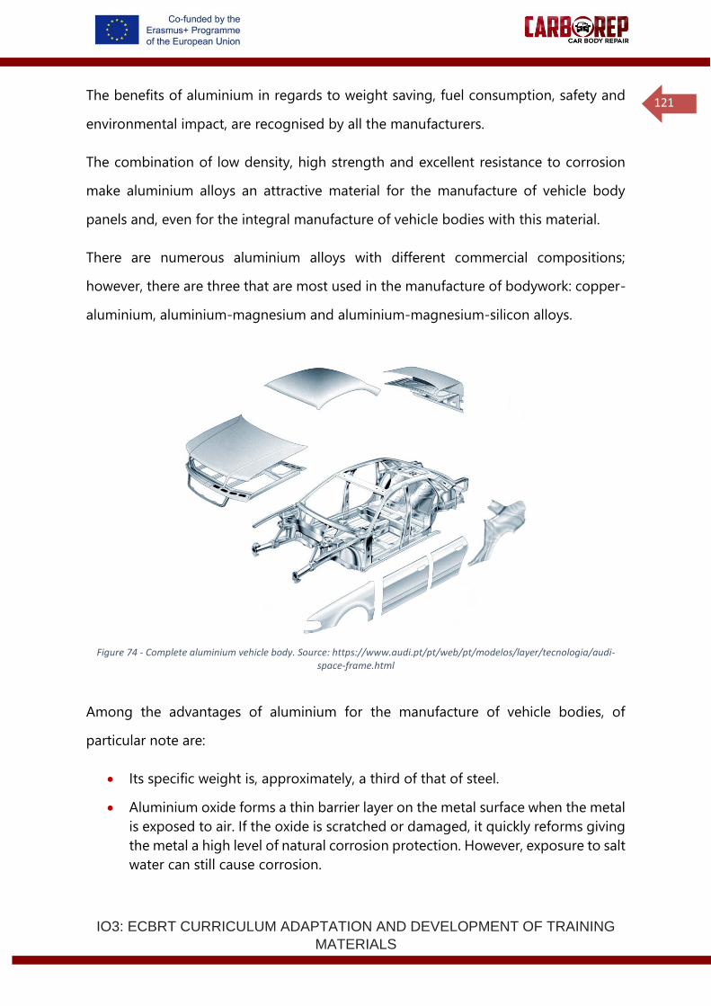
IO3: ECBRT CURRICULUM ADAPTATION AND DEVELOPMENT OF TRAINING
MATERIALS
121
The benefits of aluminium in regards to weight saving, fuel consumption, safety and
environmental impact, are recognised by all the manufacturers.
The combination of low density, high strength and excellent resistance to corrosion
make aluminium alloys an attractive material for the manufacture of vehicle body
panels and, even for the integral manufacture of vehicle bodies with this material.
There are numerous aluminium alloys with different commercial compositions;
however, there are three that are most used in the manufacture of bodywork: copper-
aluminium, aluminium-magnesium and aluminium-magnesium-silicon alloys.
Figure 74 - Complete aluminium vehicle body. Source: https://www.audi.pt/pt/web/pt/modelos/layer/tecnologia/audi-space-frame.html
Among the advantages of aluminium for the manufacture of vehicle bodies, of
particular note are:
• Its specific weight is, approximately, a third of that of steel.
• Aluminium oxide forms a thin barrier layer on the metal surface when the metal
is exposed to air. If the oxide is scratched or damaged, it quickly reforms giving
the metal a high level of natural corrosion protection. However, exposure to salt
water can still cause corrosion.
IO3: ECBRT CURRICULUM ADAPTATION AND DEVELOPMENT OF TRAINING
MATERIALS
122
• Aluminium alloys can be recycled easily at the end of their useful life.
• Less energy is needed for reuse than for steel.
• It shapes well.
• It is suitable for joining by means of MIG (Metal Inert Gas) welding.
• It has a high capacity to absorb energy in a crash.
• It is not toxic.
Plastic
It is customary to denominate all compounds of organic nature that are easily
deformable when subjected to pressure or temperature under the generic name of
plastics; however, not all plastics behave this way. Due to the inclusion of a series of
additives or reinforcements, in particular glass or carbon fibres, these fibres reinforced
composite materials have extremely high strength to weight ratios.
Over the last few decades the use of plastics in industry has increased dramatically.
The automobile industry, needless to say, has not been untouched by this trend, and
uses plastic practically to the exclusion of anything else in the manufacture of elements
such as bumpers, hubcaps, and a host of parts within the interior of the vehicle. An
average typical automobile today owes approximately 120 kg of its weight to these
materials, which is around 10% of the total vehicle weight.
Plastic use is not only limited to the manufacture of accessories and small parts; it has
also taken on a significant role in the manufacture of panels and vehicle body elements
or in the case of fibre reinforced composites, entire vehicle bodies.
The advantages of plastics are:
• Good dent resistance. In this case, plastic bodywork tolerates the impact by
flexing slightly, and recovering its original shape after the impact.
• The bodywork is not affected by corrosion, which is a major disadvantage for
steel bodywork. Steel corrosion is even responsible for limiting the life of the
automobile.
IO3: ECBRT CURRICULUM ADAPTATION AND DEVELOPMENT OF TRAINING
MATERIALS
123
• Plastic vehicle bodies are much lighter than their steel equivalents. For example,
it can be stated that a bonnet manufactured in plastic weighs around 9.2kg,
while a steel bonnet can reach 17kg.
Composite material
The term "composite material" is reserved for those materials (generally two-phase)
made up of two or more different materials which, when properly combined, improve
the final properties.
Within the field of composite materials, three types can be distinguished, according to
the type of matrix used: organic matrix composites, ceramic matrix composites and
metallic matrix composites.
In the automotive sector we are concerned with the ones most often used, organic
matrix composites, with an addition of fibres to achieve extremely high strength and
stiffness. Fibres are typically made from glass or carbon (and in some instances
aramid). The fibres can be arranged in a very wide variety of patterns to achieve the
specific mechanical performance requirements.
The matrix plays the role of the joining element, shaping the composite material
geometrically. It is normally relatively flexible but not very strong. Its main mission is
to keep the fibres united and unified, transmitting the forces of one type of fibre to
the other.
As well as ensuring the fibres join together, it also provides hardness, hermetic sealing,
and resistance to compression.
2.2 ADHESIVE BONDING IN CAR BODY REPAIR
Adhesive bonding consists of using a non-metallic substance which undergoes a
physical or chemical hardening reaction causing the parts to join together through
surface adherence (adhesion) and internal strength (cohesion). It is a good practice to
IO3: ECBRT CURRICULUM ADAPTATION AND DEVELOPMENT OF TRAINING
MATERIALS
124
ensure that the joining surfaces are properly cleaned, since contaminants may prevent
the adhesive from bonding to the base material. The adhesive requires time to cure,
which should be taken into account during the repair procedure.
Adhesive bonding enables the joining of different types of materials (e.g. steel and
aluminium), which is a capability a welding technique often lacks. Another advantage
of this joining method is that it does not generate thermally or mechanically weakened
zones around a joint.
Although adhesive bonding can be used in many applications within the automotive
industry, from sealing to glass bonding, the focus here will be on its use within repair
procedures. Adhesive Bonding can be used to attach a replacement component to the
vehicle as well in the manufacture of the new part. Structural bonding repairs are
possible if the workshop complies with the required conditions. If it cannot be
guaranteed that the adhesive can withstand the mechanical stresses predicted, then
mechanical fasteners may be used as well.
2.2.1 Types of Adhesives
An adhesive is a material that is capable of establishing bonding processes between
two adherent working pieces and developing cohesion strengths. As a result, it
provides an internal resistance to the separation of the two pieces, without structural
changes being made.
In the field of adhesives, different classifications can be established, taking into account
different concepts: physical form, chemical base, physical-chemical characteristics of
the joint, structure of the adhesive once cured, etc.
In the field of car body joining, the most frequently used adhesives are organic-
synthetic, the curing of which is performed by chemical reaction, epoxy resins (EP),
polyurethanes (PUR) and cyanoacrylates (CA). (Regulation UNE-EN 923 lists all the
types of adhesives, terms and definitions).
IO3: ECBRT CURRICULUM ADAPTATION AND DEVELOPMENT OF TRAINING
MATERIALS
125
Epoxy resins
Epoxy adhesives are made up of an epoxy resin and a hardener. They consist of one or
two parts, monocomponent resins or bicomponent resins. In car body production
lines, the main adhesive used is a single component epoxy resin, which cures during
the thermal cycle of the vehicle coating process (E-coating). In vehicle repair, the most
common adhesive type is the two-component epoxy, where the chemical curing
reaction takes place at room temperature.
There are different resins and hardeners, which give rise to a wide variety of
formulations and performances.
Their main characteristics are:
• Excellent adhesion on different substrates, such as metals, plastics, ceramics,
etc., due mainly to their capacity for moisture absorption and low viscosity.
• If the preparation and application of the adhesive has been correctly
undertaken, they generally offer good resistance to faults due to cohesion.
• These resins cure without releasing water or other sub-products, thus avoiding
trapping gases and porosities in the join. During curing, only a slight contraction
occurs. For two component epoxies, curing is undertaken at ambient
temperature, thus allowing the choice of simple and economical drying
processes.
• Their curing time varies widely, depending on the type of resin; generally, the
ones that have a quick time are more elastic than those with a slow curing time.
• They have good resistance to damp and good chemical resistance.
• They are available in tins for mixing and manual application, or in cartridges for
application with a gun and mixing tube.
IO3: ECBRT CURRICULUM ADAPTATION AND DEVELOPMENT OF TRAINING
MATERIALS
126
Polyurethane
Polyurethanes are synthetic polymers based on the chemistry of the isocyanate, which
arise from the reaction of a polyol with an isocyanate. They can be in the form of
monocomponent or bicomponent adhesives.
✓ Monocomponent polyurethanes (1K)
Monocomponent polyurethanes react with the ambient moisture to generate an
elastomer rubber. The polymerisation reaction takes place from the outside of the
bead towards the inside, and this circumstance limits the thickness of the bead, and
has influence on the curing times.
Their main characteristics are:
• Low solvent content.
• Drying by means of the absorption of moisture.
• The drying process is slow and from the outside in.
• High elasticity.
• Sensitivity to ultraviolet rays, which attack and decompose them.
• Their properties, from the structural point of view, are inferior to those of the
bicomponent polyurethanes and epoxy resins.
• Available in tubes or bags for application by means of extrusion.
• Applied in window bonding, door panel joining and joint seals.
✓ Bicomponent polyurethanes (2K)
Bicomponent polyurethanes polymerise because of the reaction of the isocyanates
with the corresponding polyols or amines.
Their main characteristics are:
• They do not need ambient moisture to polymerise. Curing is produced by the
chemical reaction of their components.
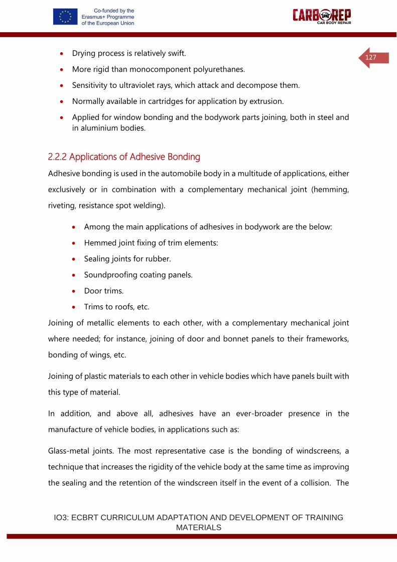
IO3: ECBRT CURRICULUM ADAPTATION AND DEVELOPMENT OF TRAINING
MATERIALS
127
• Drying process is relatively swift.
• More rigid than monocomponent polyurethanes.
• Sensitivity to ultraviolet rays, which attack and decompose them.
• Normally available in cartridges for application by extrusion.
• Applied for window bonding and the bodywork parts joining, both in steel and
in aluminium bodies.
2.2.2 Applications of Adhesive Bonding
Adhesive bonding is used in the automobile body in a multitude of applications, either
exclusively or in combination with a complementary mechanical joint (hemming,
riveting, resistance spot welding).
• Among the main applications of adhesives in bodywork are the below:
• Hemmed joint fixing of trim elements:
• Sealing joints for rubber.
• Soundproofing coating panels.
• Door trims.
• Trims to roofs, etc.
Joining of metallic elements to each other, with a complementary mechanical joint
where needed; for instance, joining of door and bonnet panels to their frameworks,
bonding of wings, etc.
Joining of plastic materials to each other in vehicle bodies which have panels built with
this type of material.
In addition, and above all, adhesives have an ever-broader presence in the
manufacture of vehicle bodies, in applications such as:
Glass-metal joints. The most representative case is the bonding of windscreens, a
technique that increases the rigidity of the vehicle body at the same time as improving
the sealing and the retention of the windscreen itself in the event of a collision. The
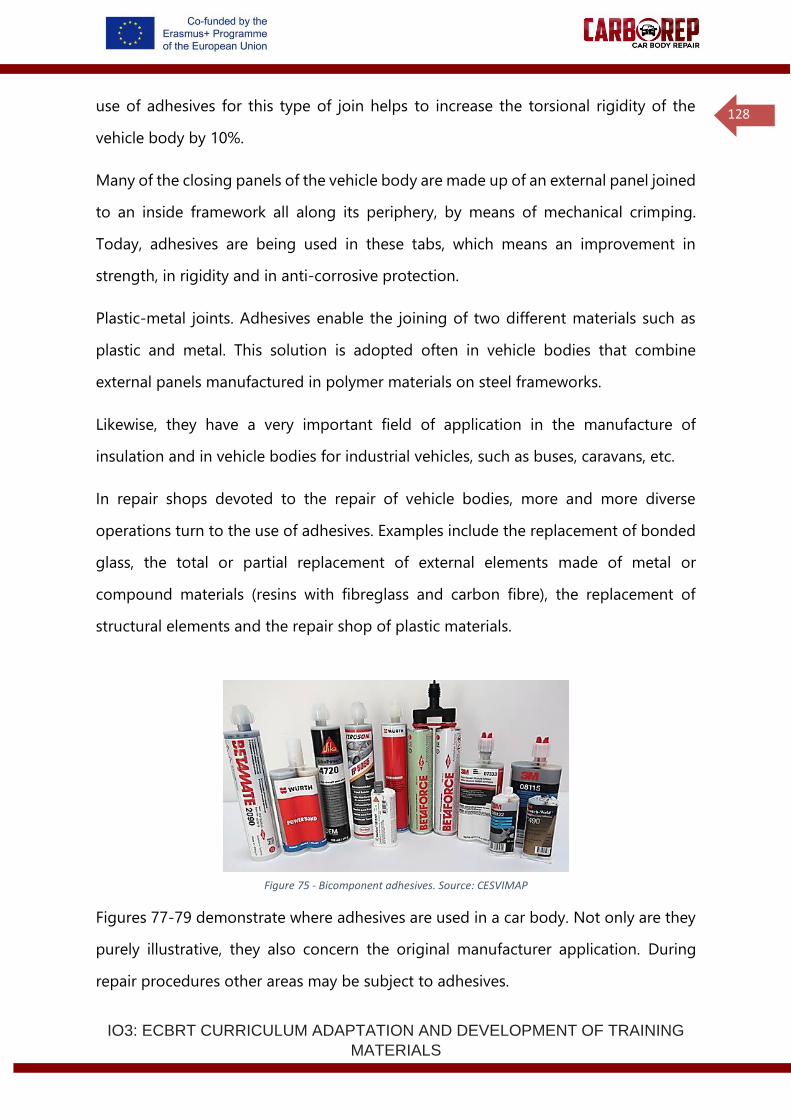
IO3: ECBRT CURRICULUM ADAPTATION AND DEVELOPMENT OF TRAINING
MATERIALS
128
use of adhesives for this type of join helps to increase the torsional rigidity of the
vehicle body by 10%.
Many of the closing panels of the vehicle body are made up of an external panel joined
to an inside framework all along its periphery, by means of mechanical crimping.
Today, adhesives are being used in these tabs, which means an improvement in
strength, in rigidity and in anti-corrosive protection.
Plastic-metal joints. Adhesives enable the joining of two different materials such as
plastic and metal. This solution is adopted often in vehicle bodies that combine
external panels manufactured in polymer materials on steel frameworks.
Likewise, they have a very important field of application in the manufacture of
insulation and in vehicle bodies for industrial vehicles, such as buses, caravans, etc.
In repair shops devoted to the repair of vehicle bodies, more and more diverse
operations turn to the use of adhesives. Examples include the replacement of bonded
glass, the total or partial replacement of external elements made of metal or
compound materials (resins with fibreglass and carbon fibre), the replacement of
structural elements and the repair shop of plastic materials.
Figure 75 - Bicomponent adhesives. Source: CESVIMAP
Figures 77-79 demonstrate where adhesives are used in a car body. Not only are they
purely illustrative, they also concern the original manufacturer application. During
repair procedures other areas may be subject to adhesives.
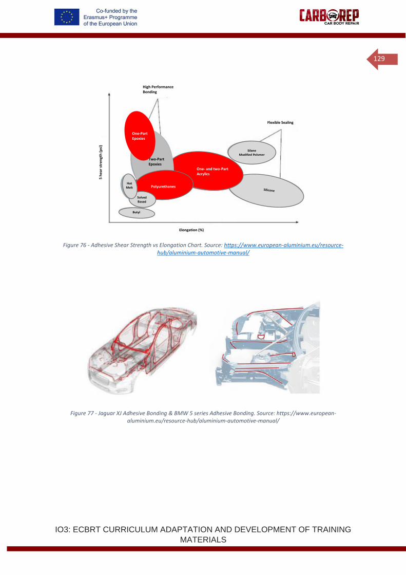
IO3: ECBRT CURRICULUM ADAPTATION AND DEVELOPMENT OF TRAINING
MATERIALS
129
Figure 76 - Adhesive Shear Strength vs Elongation Chart. Source: https://www.european-aluminium.eu/resource-hub/aluminium-automotive-manual/
Figure 77 - Jaguar XJ Adhesive Bonding & BMW 5 series Adhesive Bonding. Source: https://www.european-aluminium.eu/resource-hub/aluminium-automotive-manual/
One- and two-Part Acrylics
Two-Part Epoxies
One-Part Epoxies
Polyurethanes
Silane Modified Polymer
High Performance Bonding
Flexible Sealing
Elongation (%)
5 h
ear
stre
ngt
h (
psi
)
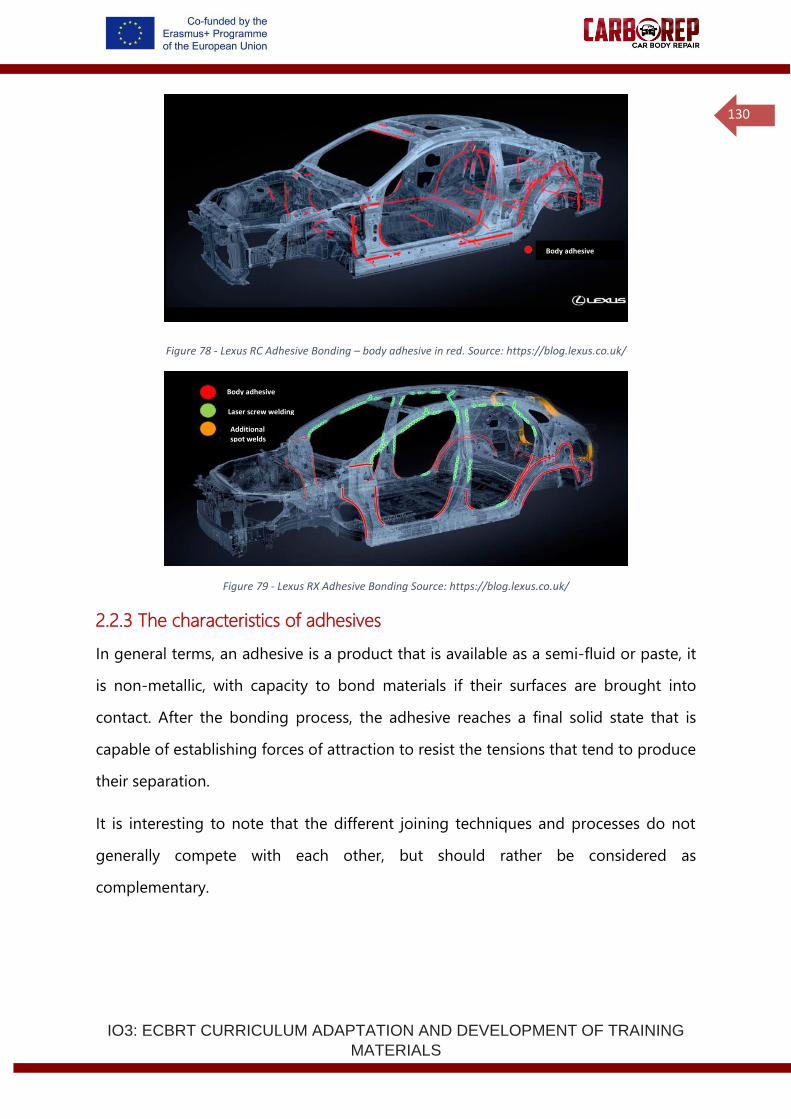
IO3: ECBRT CURRICULUM ADAPTATION AND DEVELOPMENT OF TRAINING
MATERIALS
130
Figure 78 - Lexus RC Adhesive Bonding – body adhesive in red. Source: https://blog.lexus.co.uk/
Figure 79 - Lexus RX Adhesive Bonding Source: https://blog.lexus.co.uk/
2.2.3 The characteristics of adhesives
In general terms, an adhesive is a product that is available as a semi-fluid or paste, it
is non-metallic, with capacity to bond materials if their surfaces are brought into
contact. After the bonding process, the adhesive reaches a final solid state that is
capable of establishing forces of attraction to resist the tensions that tend to produce
their separation.
It is interesting to note that the different joining techniques and processes do not
generally compete with each other, but should rather be considered as
complementary.
Body adhesive
Laser screw welding
Additional spot welds
Body adhesive
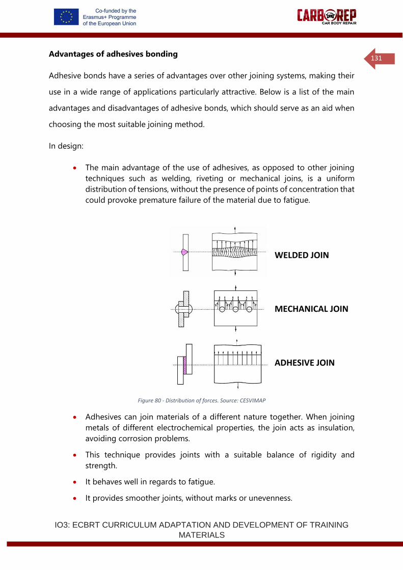
IO3: ECBRT CURRICULUM ADAPTATION AND DEVELOPMENT OF TRAINING
MATERIALS
131
Advantages of adhesives bonding
Adhesive bonds have a series of advantages over other joining systems, making their
use in a wide range of applications particularly attractive. Below is a list of the main
advantages and disadvantages of adhesive bonds, which should serve as an aid when
choosing the most suitable joining method.
In design:
• The main advantage of the use of adhesives, as opposed to other joining
techniques such as welding, riveting or mechanical joins, is a uniform
distribution of tensions, without the presence of points of concentration that
could provoke premature failure of the material due to fatigue.
Figure 80 - Distribution of forces. Source: CESVIMAP
• Adhesives can join materials of a different nature together. When joining
metals of different electrochemical properties, the join acts as insulation,
avoiding corrosion problems.
• This technique provides joints with a suitable balance of rigidity and
strength.
• It behaves well in regards to fatigue.
• It provides smoother joints, without marks or unevenness.
WELDED JOIN
MECHANICAL JOIN
ADHESIVE JOIN
IO3: ECBRT CURRICULUM ADAPTATION AND DEVELOPMENT OF TRAINING
MATERIALS
132
• It provides lighter structures, with potential for weight saving.
• It enables the joining of very thin materials.
• In production:
• One single operation can combine bonding with sealing.
• It eliminates the problems caused by heat in the welding processes
(corrosion, structural changes in the material, deformations, etc.).
• It provides very clean bonded joints, avoiding the need for further finishing
or "dressing" operations to the joint.
• Adhesive application can be automated, optimising operation times.
In service:
• Joint corrosion is reduced.
• Behaviour in regards to fatigue is improved.
• Car body’s structural stiffness, energy absorption in crash and noise vibration
harshness properties are improved.
Limitation of adhesives bonding
Among the main limitations involved with the use of adhesives, are the following:
• Limited resistance to temperature, with strength decreasing as temperature
increases. As a result, adhesives cannot be used in joints that will be
subjected to high temperatures. However, car body structural adhesives
usually have guaranteed properties in the range of -30oC to + 85oC, which
represents the expected extremes of car driving environment.
• The bonding process depends on time, with a minimum bonding period that
must be respected. The joint has to be fixed in place by a jig or additional
spot weld or fastener until the adhesive has cured or shows a minimum
strength so that it can be manipulated.
• Polymer adhesives are not as strong as metal. To make up for that lack of
strength, the technique is to increase the area of contact surface.
• The parameters and conditions required to achieve a good bonded joint,
such as pressure, temperature and bonding periods are very precise, as the
process tolerance can be small.
• Adhesives have very high shear strengths, but weak when loaded in peel or
cleavage mode, and this has to be taken into account when designing the
IO3: ECBRT CURRICULUM ADAPTATION AND DEVELOPMENT OF TRAINING
MATERIALS
133
joint. For this reason, the joints must be designed specifically for use with
adhesives, and operators should not adapt other joints designed for other
joining systems.
• Adhesives have limited stability and storage life, and expiry dates and
storage environment requirements must be respected.
• The properties of adhesive joints can change over time because of adhesive
aging and environmental exposure. These effects need to be taken into
account when designing a process.
2.2.4 Comparison with other joining methods
Joining techniques are applied to achieve a series of requirements, amongst which the
following factors are of importance:
• The nature of the materials to be joined, where an appropriate joining technique
should be selected, which is suited to the material characteristics.
• Structural needs, various joining process exhibit differing behaviours under
differing loading modes
• Accessibility in the area to be joined, different joining processes have specific
geometric and special requirements and in tight spaces not all processes can
be applied. Likewise, some processes require only single sided access whereas
other processes require access from both sides.
• Repair or how often the joining elements should be replaced.
• Degree of freedom in design of the parts.
Normally, in the manufacture of automobiles, we speak of assembly when referring to
parts that have a fixed joining system - generally welding, and of mounting when the
reference is to parts that have a joining system that allows easy dismounting and
mounting.
All the joining systems found in a vehicle body can be classified into three main groups:
• Removable joints: these enable the parts that they join to be removed as often
as required.
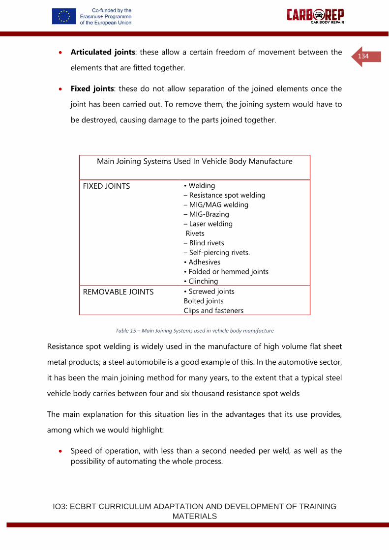
IO3: ECBRT CURRICULUM ADAPTATION AND DEVELOPMENT OF TRAINING
MATERIALS
134
• Articulated joints: these allow a certain freedom of movement between the
elements that are fitted together.
• Fixed joints: these do not allow separation of the joined elements once the
joint has been carried out. To remove them, the joining system would have to
be destroyed, causing damage to the parts joined together.
Table 15 – Main Joining Systems used in vehicle body manufacture
Resistance spot welding is widely used in the manufacture of high volume flat sheet
metal products; a steel automobile is a good example of this. In the automotive sector,
it has been the main joining method for many years, to the extent that a typical steel
vehicle body carries between four and six thousand resistance spot welds
The main explanation for this situation lies in the advantages that its use provides,
among which we would highlight:
• Speed of operation, with less than a second needed per weld, as well as the
possibility of automating the whole process.
Main Joining Systems Used In Vehicle Body Manufacture
FIXED JOINTS • Welding
– Resistance spot welding
– MIG/MAG welding
– MIG-Brazing
– Laser welding
Rivets
– Blind rivets
– Self-piercing rivets.
• Adhesives
• Folded or hemmed joints
• Clinching
REMOVABLE JOINTS • Screwed joints
Bolted joints
Clips and fasteners
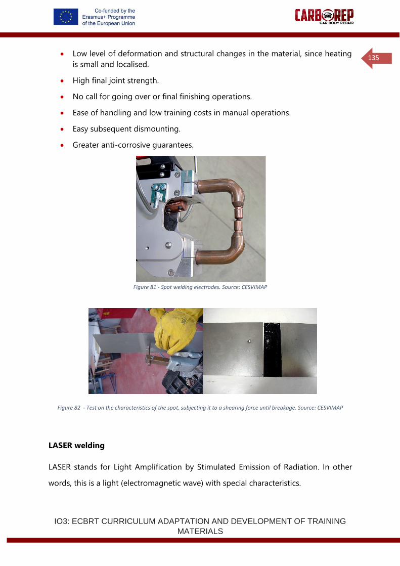
IO3: ECBRT CURRICULUM ADAPTATION AND DEVELOPMENT OF TRAINING
MATERIALS
135
• Low level of deformation and structural changes in the material, since heating
is small and localised.
• High final joint strength.
• No call for going over or final finishing operations.
• Ease of handling and low training costs in manual operations.
• Easy subsequent dismounting.
• Greater anti-corrosive guarantees.
Figure 81 - Spot welding electrodes. Source: CESVIMAP
Figure 82 - Test on the characteristics of the spot, subjecting it to a shearing force until breakage. Source: CESVIMAP
LASER welding
LASER stands for Light Amplification by Stimulated Emission of Radiation. In other
words, this is a light (electromagnetic wave) with special characteristics.
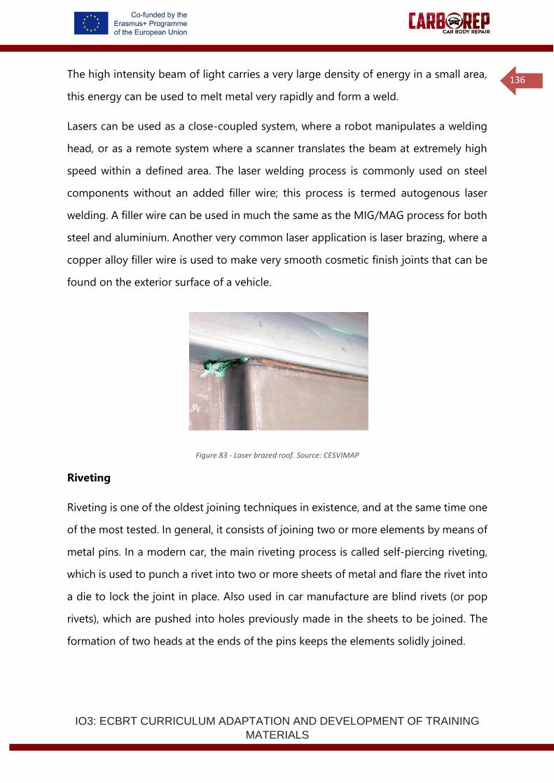
IO3: ECBRT CURRICULUM ADAPTATION AND DEVELOPMENT OF TRAINING
MATERIALS
136
The high intensity beam of light carries a very large density of energy in a small area,
this energy can be used to melt metal very rapidly and form a weld.
Lasers can be used as a close-coupled system, where a robot manipulates a welding
head, or as a remote system where a scanner translates the beam at extremely high
speed within a defined area. The laser welding process is commonly used on steel
components without an added filler wire; this process is termed autogenous laser
welding. A filler wire can be used in much the same as the MIG/MAG process for both
steel and aluminium. Another very common laser application is laser brazing, where a
copper alloy filler wire is used to make very smooth cosmetic finish joints that can be
found on the exterior surface of a vehicle.
Figure 83 - Laser brazed roof. Source: CESVIMAP
Riveting
Riveting is one of the oldest joining techniques in existence, and at the same time one
of the most tested. In general, it consists of joining two or more elements by means of
metal pins. In a modern car, the main riveting process is called self-piercing riveting,
which is used to punch a rivet into two or more sheets of metal and flare the rivet into
a die to lock the joint in place. Also used in car manufacture are blind rivets (or pop
rivets), which are pushed into holes previously made in the sheets to be joined. The
formation of two heads at the ends of the pins keeps the elements solidly joined.
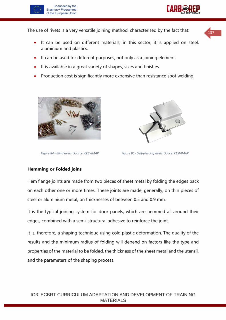
IO3: ECBRT CURRICULUM ADAPTATION AND DEVELOPMENT OF TRAINING
MATERIALS
137
The use of rivets is a very versatile joining method, characterised by the fact that:
• It can be used on different materials; in this sector, it is applied on steel,
aluminium and plastics.
• It can be used for different purposes, not only as a joining element.
• It is available in a great variety of shapes, sizes and finishes.
• Production cost is significantly more expensive than resistance spot welding.
Figure 84 - Blind rivets. Source: CESVIMAP Figure 85 - Self-piercing rivets. Souce: CESVIMAP
Hemming or Folded joins
Hem flange joints are made from two pieces of sheet metal by folding the edges back
on each other one or more times. These joints are made, generally, on thin pieces of
steel or aluminium metal, on thicknesses of between 0.5 and 0.9 mm.
It is the typical joining system for door panels, which are hemmed all around their
edges, combined with a semi-structural adhesive to reinforce the joint.
It is, therefore, a shaping technique using cold plastic deformation. The quality of the
results and the minimum radius of folding will depend on factors like the type and
properties of the material to be folded, the thickness of the sheet metal and the utensil,
and the parameters of the shaping process.
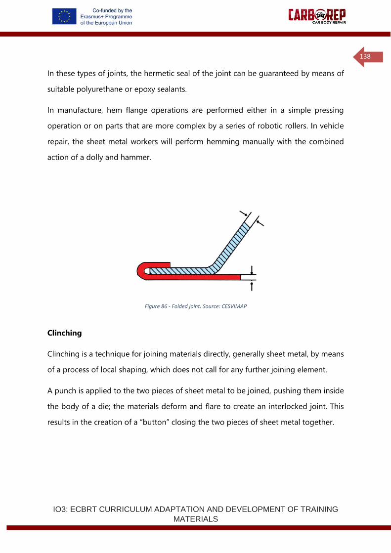
IO3: ECBRT CURRICULUM ADAPTATION AND DEVELOPMENT OF TRAINING
MATERIALS
138
In these types of joints, the hermetic seal of the joint can be guaranteed by means of
suitable polyurethane or epoxy sealants.
In manufacture, hem flange operations are performed either in a simple pressing
operation or on parts that are more complex by a series of robotic rollers. In vehicle
repair, the sheet metal workers will perform hemming manually with the combined
action of a dolly and hammer.
Figure 86 - Folded joint. Source: CESVIMAP
Clinching
Clinching is a technique for joining materials directly, generally sheet metal, by means
of a process of local shaping, which does not call for any further joining element.
A punch is applied to the two pieces of sheet metal to be joined, pushing them inside
the body of a die; the materials deform and flare to create an interlocked joint. This
results in the creation of a “button” closing the two pieces of sheet metal together.
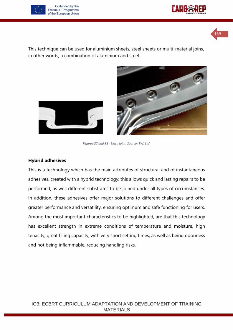
IO3: ECBRT CURRICULUM ADAPTATION AND DEVELOPMENT OF TRAINING
MATERIALS
139
This technique can be used for aluminium sheets, steel sheets or multi-material joins,
in other words, a combination of aluminium and steel.
Figures 87 and 88 - Linch joint. Source: TWI Ltd.
Hybrid adhesives
This is a technology which has the main attributes of structural and of instantaneous
adhesives, created with a hybrid technology; this allows quick and lasting repairs to be
performed, as well different substrates to be joined under all types of circumstances.
In addition, these adhesives offer major solutions to different challenges and offer
greater performance and versatility, ensuring optimum and safe functioning for users.
Among the most important characteristics to be highlighted, are that this technology
has excellent strength in extreme conditions of temperature and moisture, high
tenacity, great filling capacity, with very short setting times, as well as being odourless
and not being inflammable, reducing handling risks.
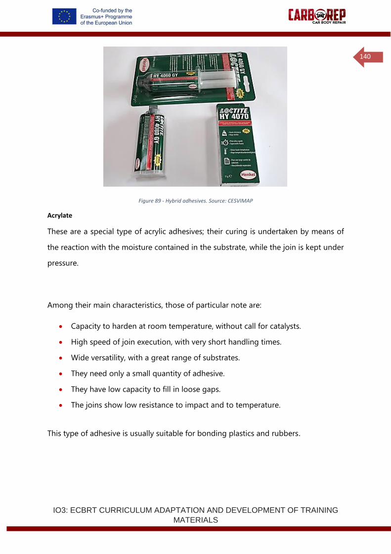
IO3: ECBRT CURRICULUM ADAPTATION AND DEVELOPMENT OF TRAINING
MATERIALS
140
Figure 89 - Hybrid adhesives. Source: CESVIMAP
Acrylate
These are a special type of acrylic adhesives; their curing is undertaken by means of
the reaction with the moisture contained in the substrate, while the join is kept under
pressure.
Among their main characteristics, those of particular note are:
• Capacity to harden at room temperature, without call for catalysts.
• High speed of join execution, with very short handling times.
• Wide versatility, with a great range of substrates.
• They need only a small quantity of adhesive.
• They have low capacity to fill in loose gaps.
• The joins show low resistance to impact and to temperature.
This type of adhesive is usually suitable for bonding plastics and rubbers.
IO3: ECBRT CURRICULUM ADAPTATION AND DEVELOPMENT OF TRAINING
MATERIALS
141
2.2.5 Mechanical testing
The object of mechanical testing is to determine the mechanical characteristics of,
strength, elasticity deformation, deformation and behaviour and reliability over time.
In 1979, Schliekelmann performed a test on the comparison of resistance to fatigue of
different joining methods of the same sizes. The results show that a riveted joint
tolerates 211,000 cycles of life to fatigue, a joint that is riveted and bonded with elastic
adhesive 420,000 cycles, and a joint that is riveted and bonded with bicomponent
epoxy 1,500,000 cycles.
For these reasons, the manufacturers subject adhesives to test methods and models
of durability prediction.
2.2.6 Adhesives technical application in car body repair
According to regulation UNE-EN 923, adhesion is the state in which two surfaces are
kept joined by means the joining of surfaces, and cohesion is the state in which
particles of a simple substance join by means of intermolecular forces. To ensure a
successful joint, it is vital for there to be intimate contact between the substrate and
the adhesive.
One of the requisites needed, although not sufficient by itself, so that adhesion
between two materials can take place is that the material ‘wets’ the other, and this
depends on the surface energy of the substrate and on the surface tension of the
liquid. If the wettability of a surface to the adhesive is good, then the adhesive spreads
naturally, in the case of poor wettability the adhesive will not spread and will stand up
off the surface with a high edge angle.
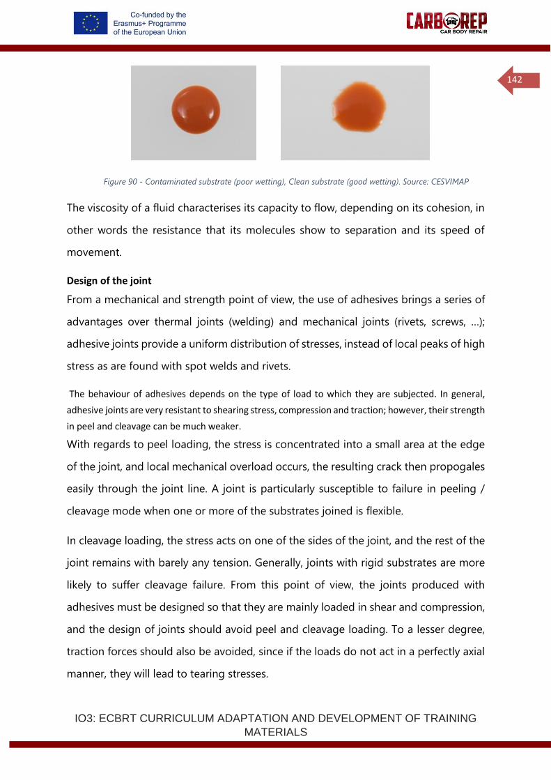
IO3: ECBRT CURRICULUM ADAPTATION AND DEVELOPMENT OF TRAINING
MATERIALS
142
Figure 90 - Contaminated substrate (poor wetting), Clean substrate (good wetting). Source: CESVIMAP
The viscosity of a fluid characterises its capacity to flow, depending on its cohesion, in
other words the resistance that its molecules show to separation and its speed of
movement.
Design of the joint
From a mechanical and strength point of view, the use of adhesives brings a series of
advantages over thermal joints (welding) and mechanical joints (rivets, screws, …);
adhesive joints provide a uniform distribution of stresses, instead of local peaks of high
stress as are found with spot welds and rivets.
The behaviour of adhesives depends on the type of load to which they are subjected. In general,
adhesive joints are very resistant to shearing stress, compression and traction; however, their strength
in peel and cleavage can be much weaker.
With regards to peel loading, the stress is concentrated into a small area at the edge
of the joint, and local mechanical overload occurs, the resulting crack then propogales
easily through the joint line. A joint is particularly susceptible to failure in peeling /
cleavage mode when one or more of the substrates joined is flexible.
In cleavage loading, the stress acts on one of the sides of the joint, and the rest of the
joint remains with barely any tension. Generally, joints with rigid substrates are more
likely to suffer cleavage failure. From this point of view, the joints produced with
adhesives must be designed so that they are mainly loaded in shear and compression,
and the design of joints should avoid peel and cleavage loading. To a lesser degree,
traction forces should also be avoided, since if the loads do not act in a perfectly axial
manner, they will lead to tearing stresses.
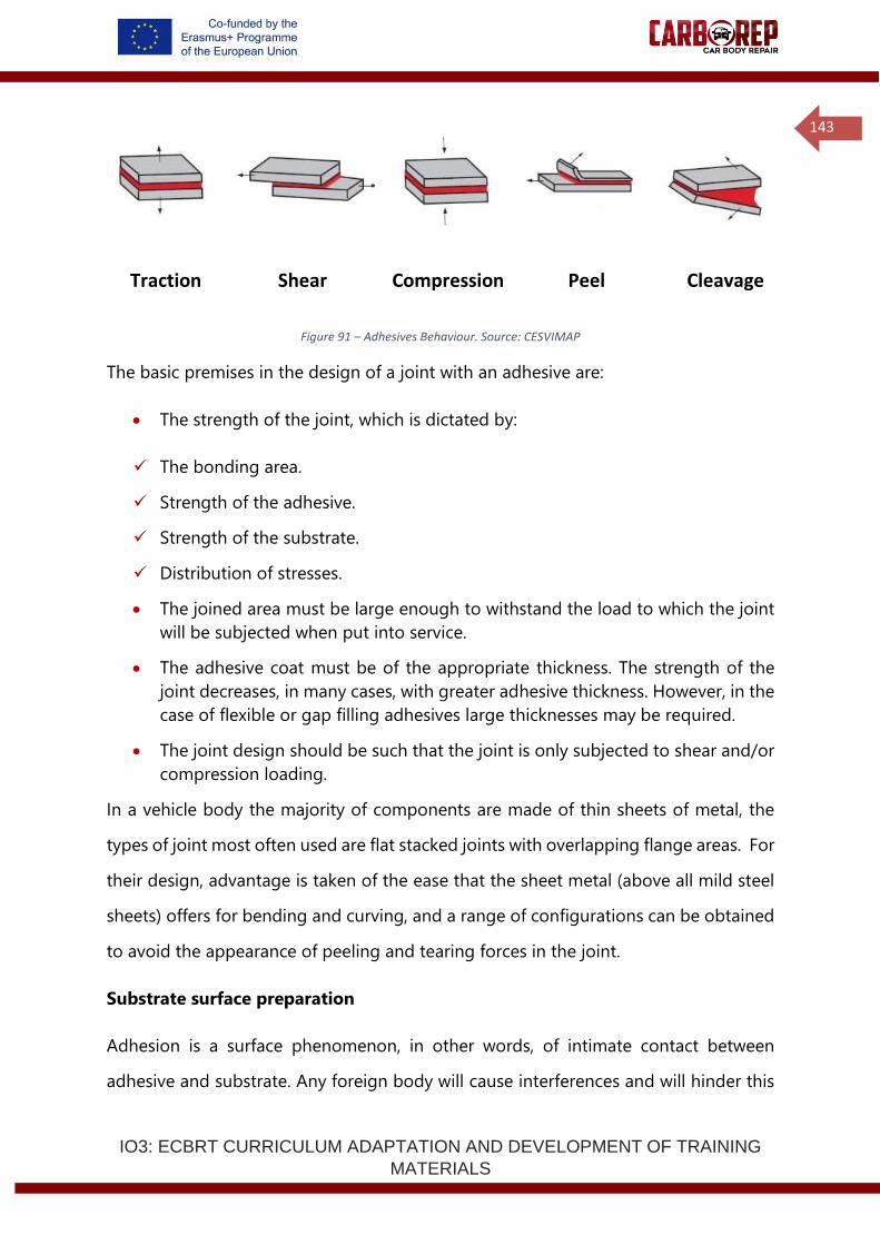
IO3: ECBRT CURRICULUM ADAPTATION AND DEVELOPMENT OF TRAINING
MATERIALS
143
Types of load
Figure 91 – Adhesives Behaviour. Source: CESVIMAP
The basic premises in the design of a joint with an adhesive are:
• The strength of the joint, which is dictated by:
✓ The bonding area.
✓ Strength of the adhesive.
✓ Strength of the substrate.
✓ Distribution of stresses.
• The joined area must be large enough to withstand the load to which the joint
will be subjected when put into service.
• The adhesive coat must be of the appropriate thickness. The strength of the
joint decreases, in many cases, with greater adhesive thickness. However, in the
case of flexible or gap filling adhesives large thicknesses may be required.
• The joint design should be such that the joint is only subjected to shear and/or
compression loading.
In a vehicle body the majority of components are made of thin sheets of metal, the
types of joint most often used are flat stacked joints with overlapping flange areas. For
their design, advantage is taken of the ease that the sheet metal (above all mild steel
sheets) offers for bending and curving, and a range of configurations can be obtained
to avoid the appearance of peeling and tearing forces in the joint.
Substrate surface preparation
Adhesion is a surface phenomenon, in other words, of intimate contact between
adhesive and substrate. Any foreign body will cause interferences and will hinder this
Traction Shear Compression Peel Cleavage
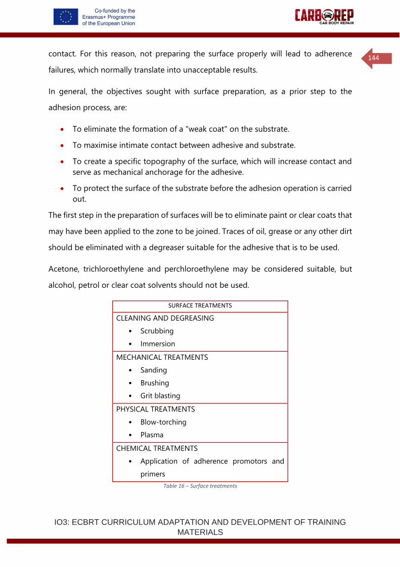
IO3: ECBRT CURRICULUM ADAPTATION AND DEVELOPMENT OF TRAINING
MATERIALS
144
contact. For this reason, not preparing the surface properly will lead to adherence
failures, which normally translate into unacceptable results.
In general, the objectives sought with surface preparation, as a prior step to the
adhesion process, are:
• To eliminate the formation of a "weak coat" on the substrate.
• To maximise intimate contact between adhesive and substrate.
• To create a specific topography of the surface, which will increase contact and
serve as mechanical anchorage for the adhesive.
• To protect the surface of the substrate before the adhesion operation is carried
out.
The first step in the preparation of surfaces will be to eliminate paint or clear coats that
may have been applied to the zone to be joined. Traces of oil, grease or any other dirt
should be eliminated with a degreaser suitable for the adhesive that is to be used.
Acetone, trichloroethylene and perchloroethylene may be considered suitable, but
alcohol, petrol or clear coat solvents should not be used.
SURFACE TREATMENTS
CLEANING AND DEGREASING
• Scrubbing
• Immersion
MECHANICAL TREATMENTS
• Sanding
• Brushing
• Grit blasting
PHYSICAL TREATMENTS
• Blow-torching
• Plasma
CHEMICAL TREATMENTS
• Application of adherence promotors and
primers
Table 16 – Surface treatments
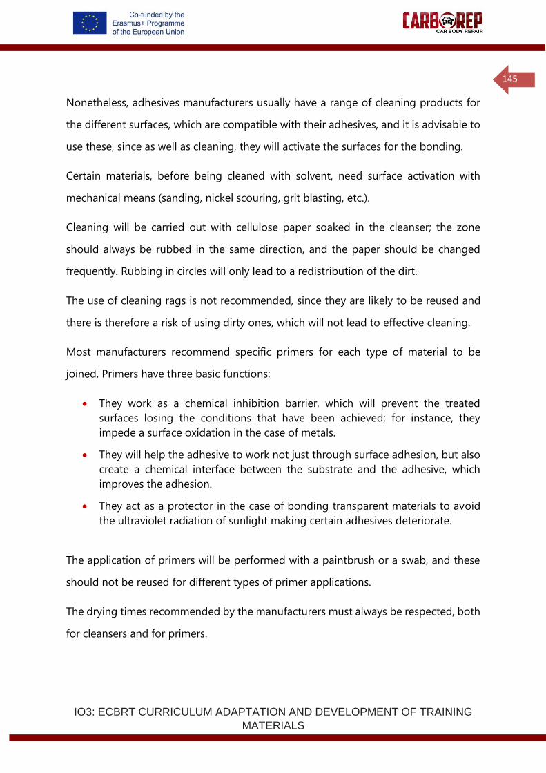
IO3: ECBRT CURRICULUM ADAPTATION AND DEVELOPMENT OF TRAINING
MATERIALS
145
Nonetheless, adhesives manufacturers usually have a range of cleaning products for
the different surfaces, which are compatible with their adhesives, and it is advisable to
use these, since as well as cleaning, they will activate the surfaces for the bonding.
Certain materials, before being cleaned with solvent, need surface activation with
mechanical means (sanding, nickel scouring, grit blasting, etc.).
Cleaning will be carried out with cellulose paper soaked in the cleanser; the zone
should always be rubbed in the same direction, and the paper should be changed
frequently. Rubbing in circles will only lead to a redistribution of the dirt.
The use of cleaning rags is not recommended, since they are likely to be reused and
there is therefore a risk of using dirty ones, which will not lead to effective cleaning.
Most manufacturers recommend specific primers for each type of material to be
joined. Primers have three basic functions:
• They work as a chemical inhibition barrier, which will prevent the treated
surfaces losing the conditions that have been achieved; for instance, they
impede a surface oxidation in the case of metals.
• They will help the adhesive to work not just through surface adhesion, but also
create a chemical interface between the substrate and the adhesive, which
improves the adhesion.
• They act as a protector in the case of bonding transparent materials to avoid
the ultraviolet radiation of sunlight making certain adhesives deteriorate.
The application of primers will be performed with a paintbrush or a swab, and these
should not be reused for different types of primer applications.
The drying times recommended by the manufacturers must always be respected, both
for cleansers and for primers.
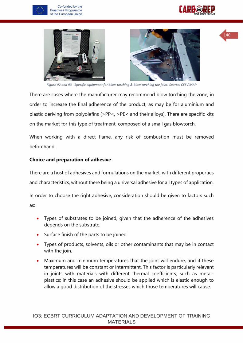
IO3: ECBRT CURRICULUM ADAPTATION AND DEVELOPMENT OF TRAINING
MATERIALS
146
Figure 92 and 93 - Specific equipment for blow-torching & Blow torching the joint. Source: CESVIMAP
There are cases where the manufacturer may recommend blow torching the zone, in
order to increase the final adherence of the product, as may be for aluminium and
plastic deriving from polyolefins (>PP<, >PE< and their alloys). There are specific kits
on the market for this type of treatment, composed of a small gas blowtorch.
When working with a direct flame, any risk of combustion must be removed
beforehand.
Choice and preparation of adhesive
There are a host of adhesives and formulations on the market, with different properties
and characteristics, without there being a universal adhesive for all types of application.
In order to choose the right adhesive, consideration should be given to factors such
as:
• Types of substrates to be joined, given that the adherence of the adhesives
depends on the substrate.
• Surface finish of the parts to be joined.
• Types of products, solvents, oils or other contaminants that may be in contact
with the join.
• Maximum and minimum temperatures that the joint will endure, and if these
temperatures will be constant or intermittent. This factor is particularly relevant
in joints with materials with different thermal coefficients, such as metal-
plastics; in this case an adhesive should be applied which is elastic enough to
allow a good distribution of the stresses which those temperatures will cause.
IO3: ECBRT CURRICULUM ADAPTATION AND DEVELOPMENT OF TRAINING
MATERIALS
147
• The rigidity of the joint and of the elements to be joined will partly condition
the rigidity of the adhesive used. The elasticity of the adhesive will adapt to the
elasticity of the substrate, and rigid adhesives should not be used to join flexible
elements.
• Size and type of demand that may have to be endured.
• Special requirements, such as thermal or electrical insulation, corrosion
prevention, etc.
• If the joint is to be spot-welded through the adhesive.
In any case, in order to make a good choice, the specifications set out by the adhesive
manufacturer must be followed.
When using monocomponent adhesives, these are provided ready for use, with no
prior preparation needed. They can be applied directly or with an extrusion, manual or
pneumatic gun.
However, if using bicomponent adhesives, they must be uniformly mixed and, in the
proportions, indicated by the manufacturer, prior to their application. This mixing can
be performed in two ways, automatically or manually.
Automatic mixing
Most bicomponent adhesives are sold in double cartridges of different capacities, and
with the mixture proportion given in the design of the cartridge itself. The diameters
of each chamber have the same ratio as the proportion of mix in volume of each
compound (1:1, 2:1, 4:1…).
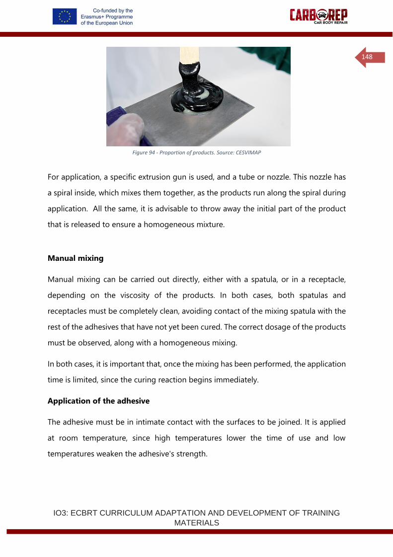
IO3: ECBRT CURRICULUM ADAPTATION AND DEVELOPMENT OF TRAINING
MATERIALS
148
Figure 94 - Proportion of products. Source: CESVIMAP
For application, a specific extrusion gun is used, and a tube or nozzle. This nozzle has
a spiral inside, which mixes them together, as the products run along the spiral during
application. All the same, it is advisable to throw away the initial part of the product
that is released to ensure a homogeneous mixture.
Manual mixing
Manual mixing can be carried out directly, either with a spatula, or in a receptacle,
depending on the viscosity of the products. In both cases, both spatulas and
receptacles must be completely clean, avoiding contact of the mixing spatula with the
rest of the adhesives that have not yet been cured. The correct dosage of the products
must be observed, along with a homogeneous mixing.
In both cases, it is important that, once the mixing has been performed, the application
time is limited, since the curing reaction begins immediately.
Application of the adhesive
The adhesive must be in intimate contact with the surfaces to be joined. It is applied
at room temperature, since high temperatures lower the time of use and low
temperatures weaken the adhesive's strength.
IO3: ECBRT CURRICULUM ADAPTATION AND DEVELOPMENT OF TRAINING
MATERIALS
149
The main aspects to be taken into account in the application of an adhesive are the
thickness of the adhesive and the shape and dimensions of the bead.
Regardless of the application system, one matter to be kept very much in mind is the
thickness of the adhesive coat. The strength of a joint can deteriorate if the bond line
is too thick.
The highest strength structural joints are obtained with thinner bond line; however, for
some filler applications of flexible adhesives (non-structural) thicker bond lines are
desired.
• The greater the quantity of adhesive, the greater the likelihood that air bubbles
will appear or foreign bodies which may weaken the join.
• The force needed to deform a thin film is greater than that needed for a greater
thickness.
• The internal tensions arising in the joining process are related to the thickness
of the film applied.
• The more the thickness increases, the greater the probability that the adhesive
seeps or crystallises.
Therefore, it is advisable to achieve thinner bond lines, but still ensure that the quantity
of adhesive is enough to completely cover the surface of the substrate and to
compensate for any shape irregularities.
For informational purposes, the maximum bond line application thickness according
to the adhesives families are:
• Cyanoacrylates: up to 0.25 mm.
• Epoxy: up to 3.0 mm.
• Polyurethanes: up to 8 mm.
These thicknesses are guidelines and will be dependent on the specific formulation of
each adhesive, meaning that in order to find out the exact data, the technical
specification sheet of the adhesive must be consulted.
IO3: ECBRT CURRICULUM ADAPTATION AND DEVELOPMENT OF TRAINING
MATERIALS
150
In certain types of applications, the final thickness of the adhesive is established by the
use of small separator blocks which, placed in the joint, will prevent the substrates
from coming too close together.
Similarly, some adhesives contain glass beads that act to separate the substrate
materials and generate a specific bond line thickness. Adhesives with glass beads are
suitable for use with blind rivets, but not with resistance spot welding.
The shape of the bead we apply will depend on the type of join to be performed. In
the case of window bonding with polyurethane adhesives, it will be a triangular bead,
and the nozzle will be given the corresponding shape.
When it is a matter of sticking bodywork panels together, a bead will be applied in the
shape of a half straw, and with a diameter of about 6 mm.
Depending on how the adhesive is administered and what its objective is, it may be
applied by extrusion, with a brush or with a spatula.
• Application by extrusion: when the adhesive is prepared in cartridges
or bags, it will be applied by extrusion, using the most suitable gun and
nozzle.
• Manually operated guns are better for intermittent or one-off
applications; pneumatic guns permit a continual application and a
constant flow.
• Brush application: the brush enables liquid or very low viscosity
adhesives to be sprinkled over a wide surface with a thin thickness. It is
very important to clean the brushes after each application. For this, it is
preferable to use hard brushes, such as nylon ones.
• Spatula application: the spatula is the best option for dense or thick
and pasty adhesives; in order to obtain higher thicknesses.
• In many cases, the use of a brush or a spatula is complementary to
application by extrusion, serving to spread the adhesive over the entire
zone of the bare metal.
IO3: ECBRT CURRICULUM ADAPTATION AND DEVELOPMENT OF TRAINING
MATERIALS
151
Once the adhesive has been applied and the part correctly placed, intimate contact all
along the joint must be ensured. For this, pressure will be exerted, spread uniformly
over the whole surface, with special care in the case of glass bonding.
There are different methods of applying pressure, according to the accessibility of the
zone:
• Self-blocking clamps: These will be used in those cases where it is possible to
put them in place, such as with tabs, part edges, etc. Various clamps are placed
along the joint, with an approximate distance of 10 centimetres between each
of them.
• In those cases where the use of clamps is not possible, such as in the cutting
lines of saving sections, other methods will be turned to.
• Fasteners: this consists of welding washers onto the bodywork part closest to
the joint and of threading fasteners through them, with a sloped geometry so
that, when they are inserted, the foot sits resting on the joint, exerting the
pressure needed.
• Washers: cut in half and welded in the shape of a bridge along the joint.
• Special devices: attached with adhesive or electromagnetic suction pads.
When the parts are made of polyester, self-tapping screws are normally used, attached
to the parts and to the following flanging strap. When the adhesive has dried, it is
removed and the hollow is filled with resin.
Adhesive curing
The reticulation or curing of the adhesive is to be understood as the group of processes
that take place from the moment when the mixture is produced and the application of
the adhesive until it has cured completely.
The speed of curing will depend on:
• The proportion of the mixture, the curing being quicker the greater the
proportion of curing agents there are.
IO3: ECBRT CURRICULUM ADAPTATION AND DEVELOPMENT OF TRAINING
MATERIALS
152
• The speed of drying will also depend on the room temperature;
temperatures above 20º C will accelerate the curing of the adhesive.
Some manufacturers will consider the application of infrared equipment
heat or in the paintwork booth to shorten drying times. However, in these
cases, the manufacturers` recommendations should be kept in mind
since incorrect heating can deteriorate the adhesive, and result in a loss
of strength in the joint.
• In the case of monocomponent polyurethanes, drying is carried out by
moisture absorption, meaning that the drying time will be inversely
proportional to the relative moisture present in the surrounding
environment.
Within the curing process, three stages can be distinguished:
• Handling time: the time that elapses between the adhesive application
and the start of the formation of a skin, when such viscosity is achieved
that no further manoeuvre is possible. This is the time the technician has
to handle joining: presentation and adjustment of the part
• Solidifying time for handling or mixture lifetime: the time that elapses
from the start of the curing until the moment when the adhesive has
acquired sufficient solidity to be able to continue with the work process.
• Curing time: the time that elapses between the start of the curing process
and the moment of its conclusion, when the maximum values of
mechanical strength are reached.
In practice, these times are often incompatible since, on the one hand, it is advisable
that the solidity time until the handling time or curing time be as short as possible in
order to carry on with the work on the vehicle. However, on the other hand, the
handling time must be, to a certain extent, ample, in order to be able to carry out
proper positioning and adjustment of the part, above all when it is a matter of large
panels.
Durability of the adhesive
The deterioration and durability of bonded joints is conditioned by temperature,
environmental conditions and the mechanical loads they have to withstand.
IO3: ECBRT CURRICULUM ADAPTATION AND DEVELOPMENT OF TRAINING
MATERIALS
153
To obtain strength during its life in service in a bonded joint, the joint must maintain
a significant proportion of its load capacity for long periods, withstand the
environmental conditions during its life in service and guarantee durability for a
specific application.
The factors that can affect the durability of a join in service conditions are:
• Static and dynamic loads
• Environmental agents (temperature, rain, moisture, saline
environment…),
• UV exposure
• Water
• Organic solvents
• Detergents
• Fuels and lubricants
One of the most common causes of failures in adhesive joins is lack of knowledge of
the force to which the assembly will be subjected.
The behaviour is very different if it is subjected to a combination of different combined
effects such as dynamic loads plus saline water and sharp changes of temperature, etc.
Of all the environmental agents, water is the substance that generates the most
problems in the durability of adhesive joints. It is also the most common medium to
which the joint finds itself subjected. By hydrating the metal, oxide is created on the
surface leading to the failure of the joint. It alters the properties of the adhesive
irreversibly by means of hydrolysis and generates cracks or craters in it, attacking the
adhesive/substrate interface by a process of displacement and displacing the adhesive,
inducing tensions due to adhesive swelling.
Creep is the permanent deformation according to the time that a material suffers when
it is subjected to a constant load; this has to do with time, temperature and humidity.
The mechanical effects of the adhesives are affected by great sensitivity to climate
IO3: ECBRT CURRICULUM ADAPTATION AND DEVELOPMENT OF TRAINING
MATERIALS
154
conditions, sensitivity to creep in certain conditions, the characteristics of the adhesive
(porosity, fissures, lack of homogeneity, deficient curing) environmental conditions
(temperature, moisture, etc.), geometry of the joint (distribution of tensions) etc.
2.2.6 Adhesive product data and safety sheets
The product data and safety sheets constitute the detailed information about the
various properties of the product, handling instructions, properties, etc. It is important
to be familiar with them when working a specific adhesive and pursuing the reduction
of work and environmental risks.
The data sheets on safety give advice about safety, precautions and risk of the product.
(Continue on the next page)
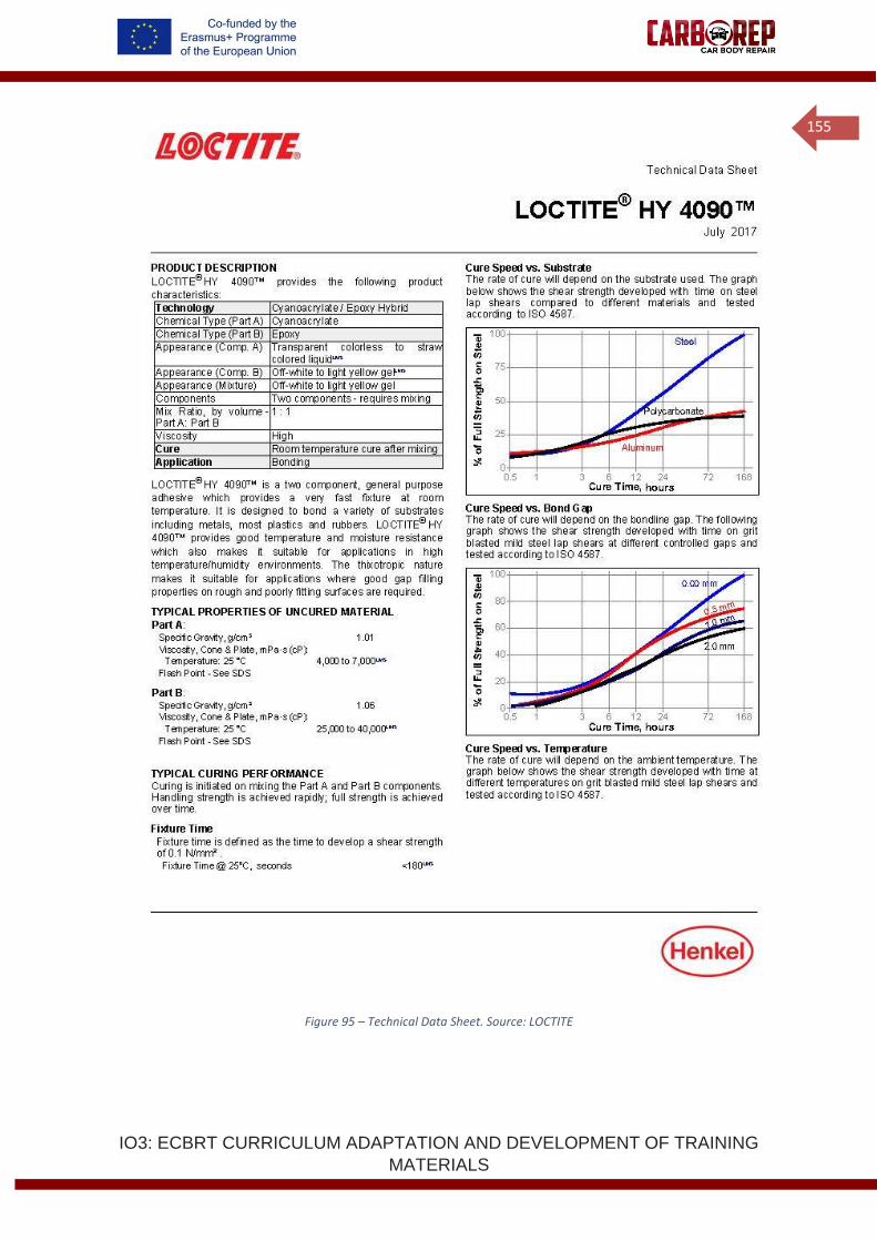
IO3: ECBRT CURRICULUM ADAPTATION AND DEVELOPMENT OF TRAINING
MATERIALS
155
Figure 95 – Technical Data Sheet. Source: LOCTITE
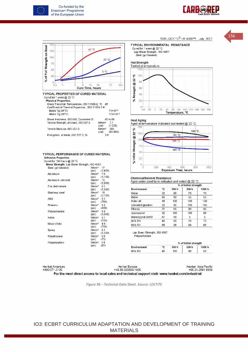
IO3: ECBRT CURRICULUM ADAPTATION AND DEVELOPMENT OF TRAINING
MATERIALS
156
Figure 96 – Technical Data Sheet. Source: LOCTITE
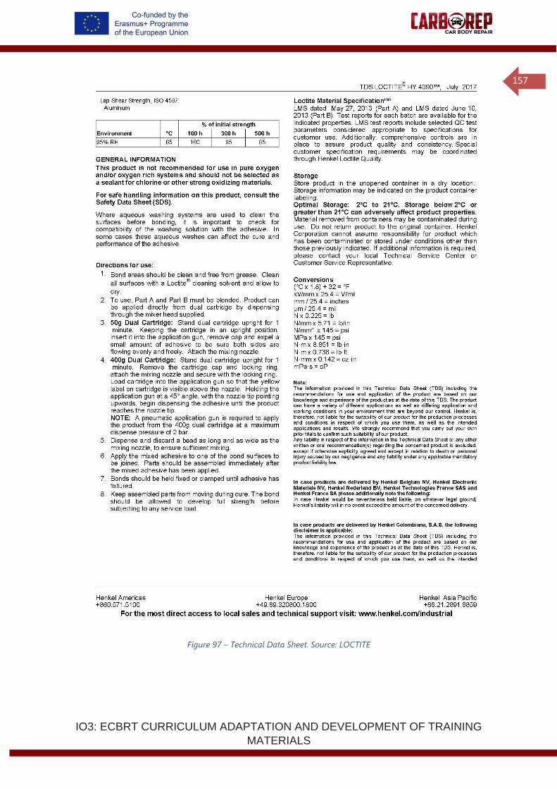
IO3: ECBRT CURRICULUM ADAPTATION AND DEVELOPMENT OF TRAINING
MATERIALS
157
Figure 97 – Technical Data Sheet. Source: LOCTITE
IO3: ECBRT CURRICULUM ADAPTATION AND DEVELOPMENT OF TRAINING
MATERIALS
158
Figure 98 – Technical Data Sheet. Source: LOCTITE
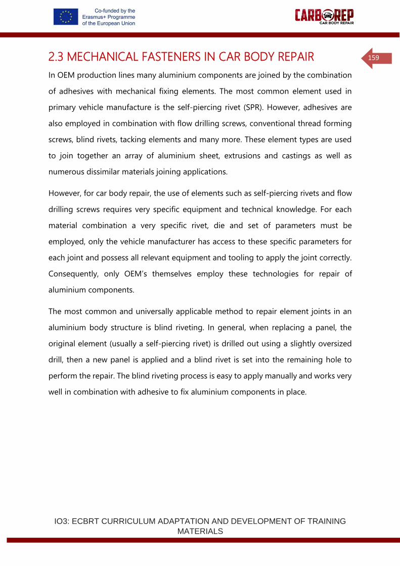
IO3: ECBRT CURRICULUM ADAPTATION AND DEVELOPMENT OF TRAINING
MATERIALS
159
2.3 MECHANICAL FASTENERS IN CAR BODY REPAIR
In OEM production lines many aluminium components are joined by the combination
of adhesives with mechanical fixing elements. The most common element used in
primary vehicle manufacture is the self-piercing rivet (SPR). However, adhesives are
also employed in combination with flow drilling screws, conventional thread forming
screws, blind rivets, tacking elements and many more. These element types are used
to join together an array of aluminium sheet, extrusions and castings as well as
numerous dissimilar materials joining applications.
However, for car body repair, the use of elements such as self-piercing rivets and flow
drilling screws requires very specific equipment and technical knowledge. For each
material combination a very specific rivet, die and set of parameters must be
employed, only the vehicle manufacturer has access to these specific parameters for
each joint and possess all relevant equipment and tooling to apply the joint correctly.
Consequently, only OEM’s themselves employ these technologies for repair of
aluminium components.
The most common and universally applicable method to repair element joints in an
aluminium body structure is blind riveting. In general, when replacing a panel, the
original element (usually a self-piercing rivet) is drilled out using a slightly oversized
drill, then a new panel is applied and a blind rivet is set into the remaining hole to
perform the repair. The blind riveting process is easy to apply manually and works very
well in combination with adhesive to fix aluminium components in place.
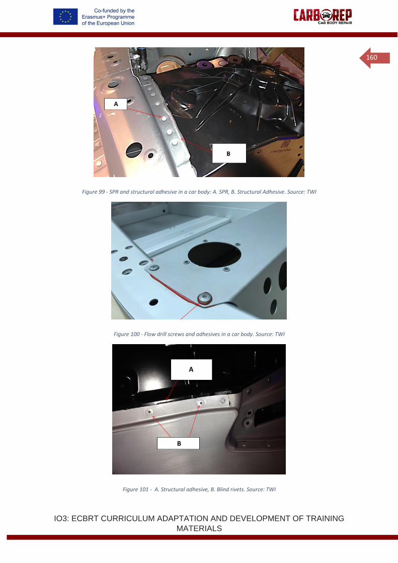
IO3: ECBRT CURRICULUM ADAPTATION AND DEVELOPMENT OF TRAINING
MATERIALS
160
Figure 99 - SPR and structural adhesive in a car body: A. SPR, B. Structural Adhesive. Source: TWI
Figure 100 - Flow drill screws and adhesives in a car body. Source: TWI
Figure 101 - A. Structural adhesive, B. Blind rivets. Source: TWI
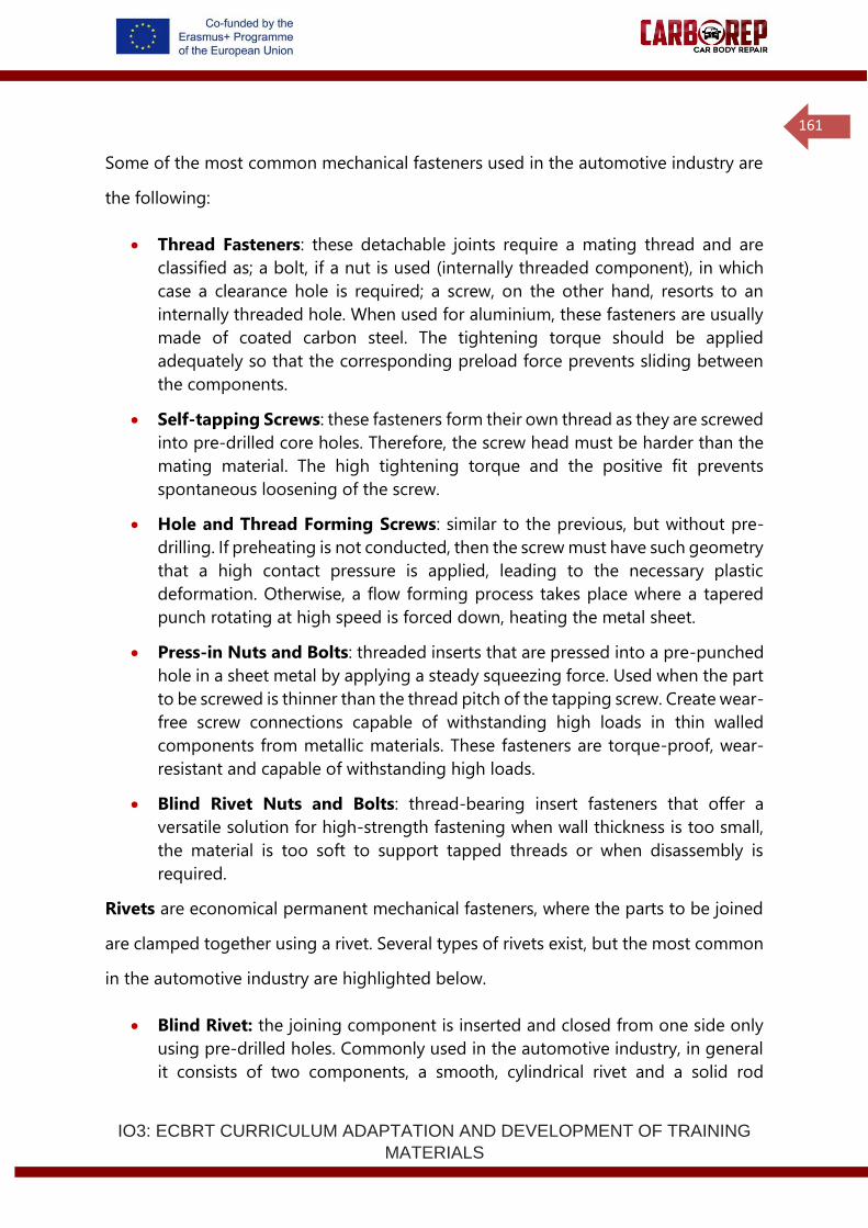
IO3: ECBRT CURRICULUM ADAPTATION AND DEVELOPMENT OF TRAINING
MATERIALS
161
Some of the most common mechanical fasteners used in the automotive industry are
the following:
• Thread Fasteners: these detachable joints require a mating thread and are
classified as; a bolt, if a nut is used (internally threaded component), in which
case a clearance hole is required; a screw, on the other hand, resorts to an
internally threaded hole. When used for aluminium, these fasteners are usually
made of coated carbon steel. The tightening torque should be applied
adequately so that the corresponding preload force prevents sliding between
the components.
• Self-tapping Screws: these fasteners form their own thread as they are screwed
into pre-drilled core holes. Therefore, the screw head must be harder than the
mating material. The high tightening torque and the positive fit prevents
spontaneous loosening of the screw.
• Hole and Thread Forming Screws: similar to the previous, but without pre-
drilling. If preheating is not conducted, then the screw must have such geometry
that a high contact pressure is applied, leading to the necessary plastic
deformation. Otherwise, a flow forming process takes place where a tapered
punch rotating at high speed is forced down, heating the metal sheet.
• Press-in Nuts and Bolts: threaded inserts that are pressed into a pre-punched
hole in a sheet metal by applying a steady squeezing force. Used when the part
to be screwed is thinner than the thread pitch of the tapping screw. Create wear-
free screw connections capable of withstanding high loads in thin walled
components from metallic materials. These fasteners are torque-proof, wear-
resistant and capable of withstanding high loads.
• Blind Rivet Nuts and Bolts: thread-bearing insert fasteners that offer a
versatile solution for high-strength fastening when wall thickness is too small,
the material is too soft to support tapped threads or when disassembly is
required.
Rivets are economical permanent mechanical fasteners, where the parts to be joined
are clamped together using a rivet. Several types of rivets exist, but the most common
in the automotive industry are highlighted below.
• Blind Rivet: the joining component is inserted and closed from one side only
using pre-drilled holes. Commonly used in the automotive industry, in general
it consists of two components, a smooth, cylindrical rivet and a solid rod
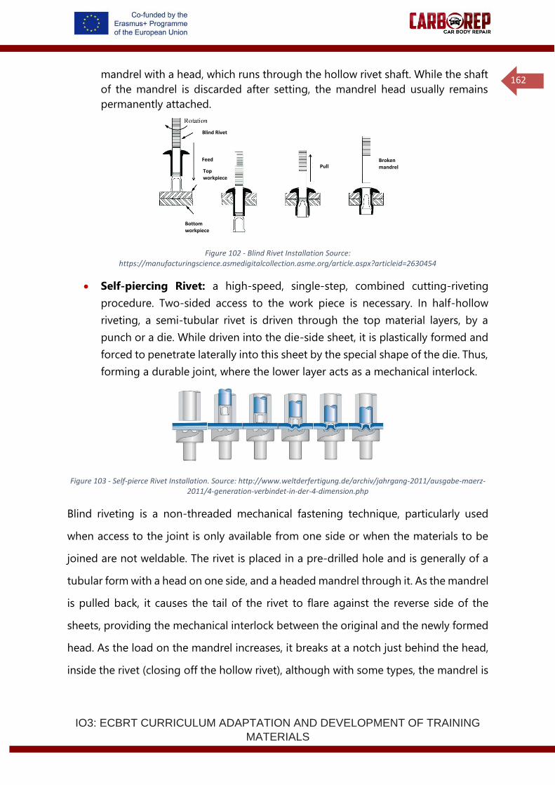
IO3: ECBRT CURRICULUM ADAPTATION AND DEVELOPMENT OF TRAINING
MATERIALS
162
mandrel with a head, which runs through the hollow rivet shaft. While the shaft
of the mandrel is discarded after setting, the mandrel head usually remains
permanently attached.
Figure 102 - Blind Rivet Installation Source: https://manufacturingscience.asmedigitalcollection.asme.org/article.aspx?articleid=2630454
• Self-piercing Rivet: a high-speed, single-step, combined cutting-riveting
procedure. Two-sided access to the work piece is necessary. In half-hollow
riveting, a semi-tubular rivet is driven through the top material layers, by a
punch or a die. While driven into the die-side sheet, it is plastically formed and
forced to penetrate laterally into this sheet by the special shape of the die. Thus,
forming a durable joint, where the lower layer acts as a mechanical interlock.
Figure 103 - Self-pierce Rivet Installation. Source: http://www.weltderfertigung.de/archiv/jahrgang-2011/ausgabe-maerz-2011/4-generation-verbindet-in-der-4-dimension.php
Blind riveting is a non-threaded mechanical fastening technique, particularly used
when access to the joint is only available from one side or when the materials to be
joined are not weldable. The rivet is placed in a pre-drilled hole and is generally of a
tubular form with a head on one side, and a headed mandrel through it. As the mandrel
is pulled back, it causes the tail of the rivet to flare against the reverse side of the
sheets, providing the mechanical interlock between the original and the newly formed
head. As the load on the mandrel increases, it breaks at a notch just behind the head,
inside the rivet (closing off the hollow rivet), although with some types, the mandrel is
Blind Rivet
Top workpiece
Rotation
Feed
Bottom workpiece
Pull
Broken mandrel
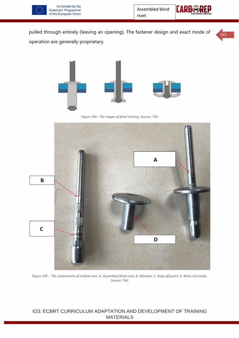
IO3: ECBRT CURRICULUM ADAPTATION AND DEVELOPMENT OF TRAINING
MATERIALS
163
pulled through entirely (leaving an opening). The fastener design and exact mode of
operation are generally proprietary.
Figure 104 - The stages of blind riveting. Source: TWI
Figure 105 - The components of a blind rivet. A. Assembled blind rivet, B. Mandrel, C. Snap off point, D. Blind rivet body. Source: TWi
Assembled blind
rivet

IO3: ECBRT CURRICULUM ADAPTATION AND DEVELOPMENT OF TRAINING
MATERIALS
164
Figure 106 - Blind rivets set in a 3-sheet material stack and a rivet cross section. Source: TWI
There are numerous quality requirements for blind riveting, importantly the correct
rivet must be selected for the sheet thickness and hole diameter into which it is to be
applied. A correctly selected and set rivet will have a mandrel break off point located
within the rivet head, not deep inside the rivet or above the head. The rivet should
close the sheets of material together and the head should fit down flush onto the
upper sheet of material.
Figure 107 - Cross section of a blind rivet showing the required quality factors. A. Mandrel fracture in rivet hear required, B. Rivet head flush to sheet, C. Gap between rivet head and upper sheet preferably closed, D. Flush fit of rivet tail to lower
sheet, E. Gaps between sheets should be closed. Source: TWI
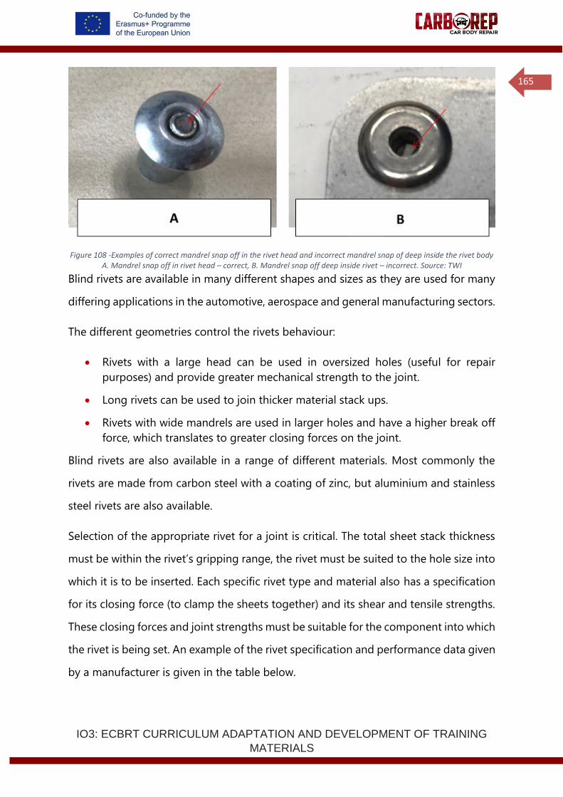
IO3: ECBRT CURRICULUM ADAPTATION AND DEVELOPMENT OF TRAINING
MATERIALS
165
Figure 108 -Examples of correct mandrel snap off in the rivet head and incorrect mandrel snap of deep inside the rivet body A. Mandrel snap off in rivet head – correct, B. Mandrel snap off deep inside rivet – incorrect. Source: TWI
Blind rivets are available in many different shapes and sizes as they are used for many
differing applications in the automotive, aerospace and general manufacturing sectors.
The different geometries control the rivets behaviour:
• Rivets with a large head can be used in oversized holes (useful for repair
purposes) and provide greater mechanical strength to the joint.
• Long rivets can be used to join thicker material stack ups.
• Rivets with wide mandrels are used in larger holes and have a higher break off
force, which translates to greater closing forces on the joint.
Blind rivets are also available in a range of different materials. Most commonly the
rivets are made from carbon steel with a coating of zinc, but aluminium and stainless
steel rivets are also available.
Selection of the appropriate rivet for a joint is critical. The total sheet stack thickness
must be within the rivet’s gripping range, the rivet must be suited to the hole size into
which it is to be inserted. Each specific rivet type and material also has a specification
for its closing force (to clamp the sheets together) and its shear and tensile strengths.
These closing forces and joint strengths must be suitable for the component into which
the rivet is being set. An example of the rivet specification and performance data given
by a manufacturer is given in the table below.
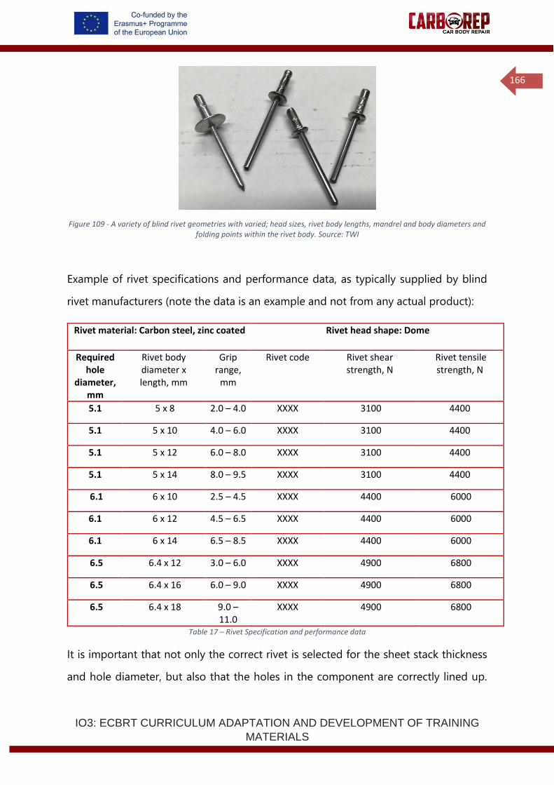
IO3: ECBRT CURRICULUM ADAPTATION AND DEVELOPMENT OF TRAINING
MATERIALS
166
Figure 109 - A variety of blind rivet geometries with varied; head sizes, rivet body lengths, mandrel and body diameters and folding points within the rivet body. Source: TWI
Example of rivet specifications and performance data, as typically supplied by blind
rivet manufacturers (note the data is an example and not from any actual product):
Rivet material: Carbon steel, zinc coated Rivet head shape: Dome
Required hole
diameter, mm
Rivet body diameter x length, mm
Grip range,
mm
Rivet code Rivet shear strength, N
Rivet tensile strength, N
5.1 5 x 8 2.0 – 4.0 XXXX 3100 4400
5.1 5 x 10 4.0 – 6.0 XXXX 3100 4400
5.1 5 x 12 6.0 – 8.0 XXXX 3100 4400
5.1 5 x 14 8.0 – 9.5 XXXX 3100 4400
6.1 6 x 10 2.5 – 4.5 XXXX 4400 6000
6.1 6 x 12 4.5 – 6.5 XXXX 4400 6000
6.1 6 x 14 6.5 – 8.5 XXXX 4400 6000
6.5 6.4 x 12 3.0 – 6.0 XXXX 4900 6800
6.5 6.4 x 16 6.0 – 9.0 XXXX 4900 6800
6.5 6.4 x 18 9.0 – 11.0
XXXX 4900 6800
Table 17 – Rivet Specification and performance data
It is important that not only the correct rivet is selected for the sheet stack thickness
and hole diameter, but also that the holes in the component are correctly lined up.
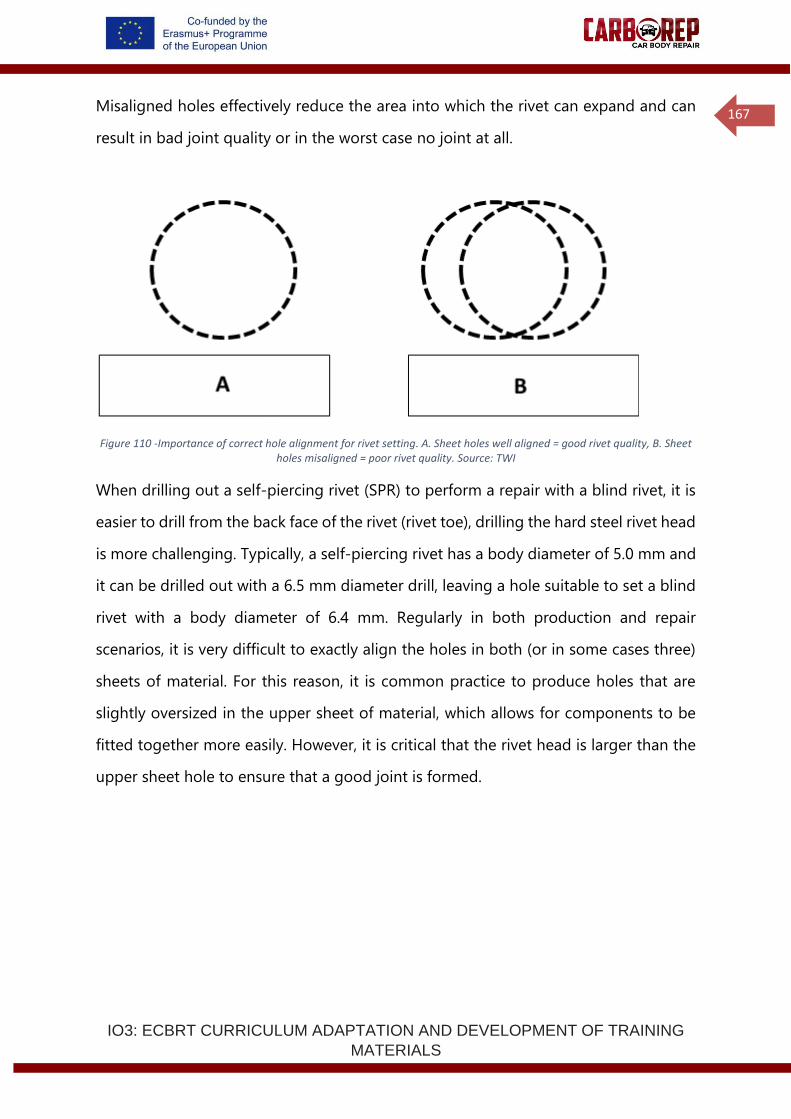
IO3: ECBRT CURRICULUM ADAPTATION AND DEVELOPMENT OF TRAINING
MATERIALS
167
Misaligned holes effectively reduce the area into which the rivet can expand and can
result in bad joint quality or in the worst case no joint at all.
Figure 110 -Importance of correct hole alignment for rivet setting. A. Sheet holes well aligned = good rivet quality, B. Sheet holes misaligned = poor rivet quality. Source: TWI
When drilling out a self-piercing rivet (SPR) to perform a repair with a blind rivet, it is
easier to drill from the back face of the rivet (rivet toe), drilling the hard steel rivet head
is more challenging. Typically, a self-piercing rivet has a body diameter of 5.0 mm and
it can be drilled out with a 6.5 mm diameter drill, leaving a hole suitable to set a blind
rivet with a body diameter of 6.4 mm. Regularly in both production and repair
scenarios, it is very difficult to exactly align the holes in both (or in some cases three)
sheets of material. For this reason, it is common practice to produce holes that are
slightly oversized in the upper sheet of material, which allows for components to be
fitted together more easily. However, it is critical that the rivet head is larger than the
upper sheet hole to ensure that a good joint is formed.
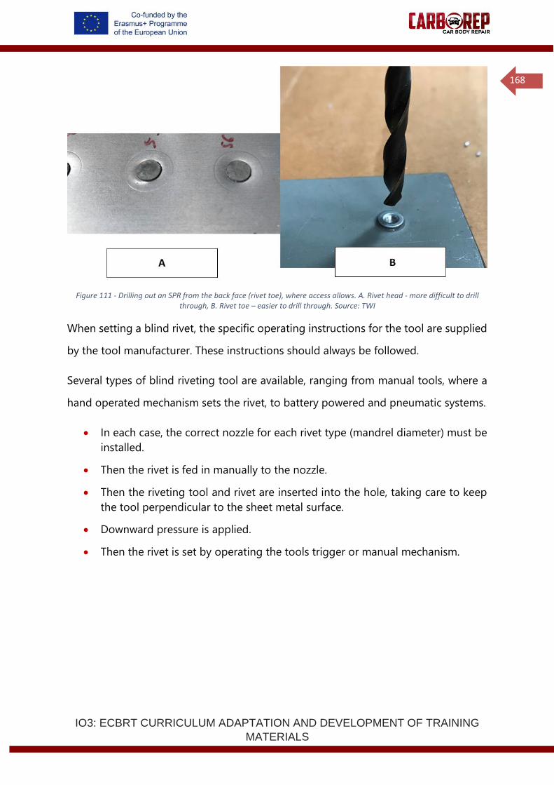
IO3: ECBRT CURRICULUM ADAPTATION AND DEVELOPMENT OF TRAINING
MATERIALS
168
Figure 111 - Drilling out an SPR from the back face (rivet toe), where access allows. A. Rivet head - more difficult to drill through, B. Rivet toe – easier to drill through. Source: TWI
When setting a blind rivet, the specific operating instructions for the tool are supplied
by the tool manufacturer. These instructions should always be followed.
Several types of blind riveting tool are available, ranging from manual tools, where a
hand operated mechanism sets the rivet, to battery powered and pneumatic systems.
• In each case, the correct nozzle for each rivet type (mandrel diameter) must be
installed.
• Then the rivet is fed in manually to the nozzle.
• Then the riveting tool and rivet are inserted into the hole, taking care to keep
the tool perpendicular to the sheet metal surface.
• Downward pressure is applied.
• Then the rivet is set by operating the tools trigger or manual mechanism.
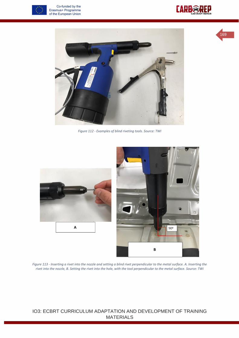
IO3: ECBRT CURRICULUM ADAPTATION AND DEVELOPMENT OF TRAINING
MATERIALS
169
Figure 112 - Examples of blind riveting tools. Source: TWI
Figure 113 - Inserting a rivet into the nozzle and setting a blind rivet perpendicular to the metal surface. A. Inserting the rivet into the nozzle, B. Setting the rivet into the hole, with the tool perpendicular to the metal surface. Source: TWi
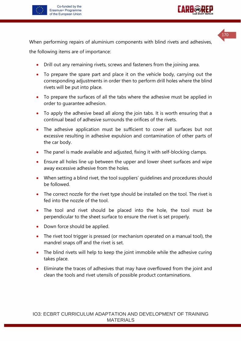
IO3: ECBRT CURRICULUM ADAPTATION AND DEVELOPMENT OF TRAINING
MATERIALS
170
When performing repairs of aluminium components with blind rivets and adhesives,
the following items are of importance:
• Drill out any remaining rivets, screws and fasteners from the joining area.
• To prepare the spare part and place it on the vehicle body, carrying out the
corresponding adjustments in order then to perform drill holes where the blind
rivets will be put into place.
• To prepare the surfaces of all the tabs where the adhesive must be applied in
order to guarantee adhesion.
• To apply the adhesive bead all along the join tabs. It is worth ensuring that a
continual bead of adhesive surrounds the orifices of the rivets.
• The adhesive application must be sufficient to cover all surfaces but not
excessive resulting in adhesive expulsion and contamination of other parts of
the car body.
• The panel is made available and adjusted, fixing it with self-blocking clamps.
• Ensure all holes line up between the upper and lower sheet surfaces and wipe
away excessive adhesive from the holes.
• When setting a blind rivet, the tool suppliers’ guidelines and procedures should
be followed.
• The correct nozzle for the rivet type should be installed on the tool. The rivet is
fed into the nozzle of the tool.
• The tool and rivet should be placed into the hole, the tool must be
perpendicular to the sheet surface to ensure the rivet is set properly.
• Down force should be applied.
• The rivet tool trigger is pressed (or mechanism operated on a manual tool), the
mandrel snaps off and the rivet is set.
• The blind rivets will help to keep the joint immobile while the adhesive curing
takes place.
• Eliminate the traces of adhesives that may have overflowed from the joint and
clean the tools and rivet utensils of possible product contaminations.
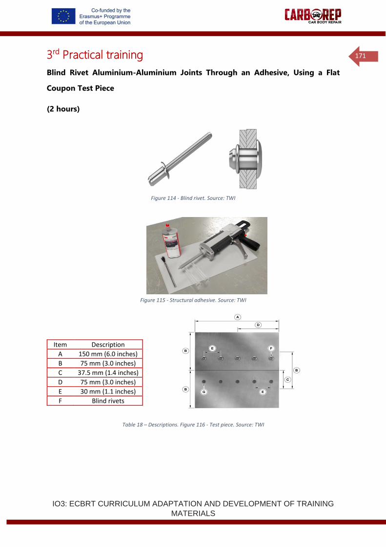
IO3: ECBRT CURRICULUM ADAPTATION AND DEVELOPMENT OF TRAINING
MATERIALS
171
3rd Practical training
Blind Rivet Aluminium-Aluminium Joints Through an Adhesive, Using a Flat
Coupon Test Piece
(2 hours)
Figure 114 - Blind rivet. Source: TWI
Figure 115 - Structural adhesive. Source: TWI
Table 18 – Descriptions. Figure 116 - Test piece. Source: TWI
Item Description
A 150 mm (6.0 inches)
B 75 mm (3.0 inches)
C 37.5 mm (1.4 inches)
D 75 mm (3.0 inches)
E 30 mm (1.1 inches)
F Blind rivets
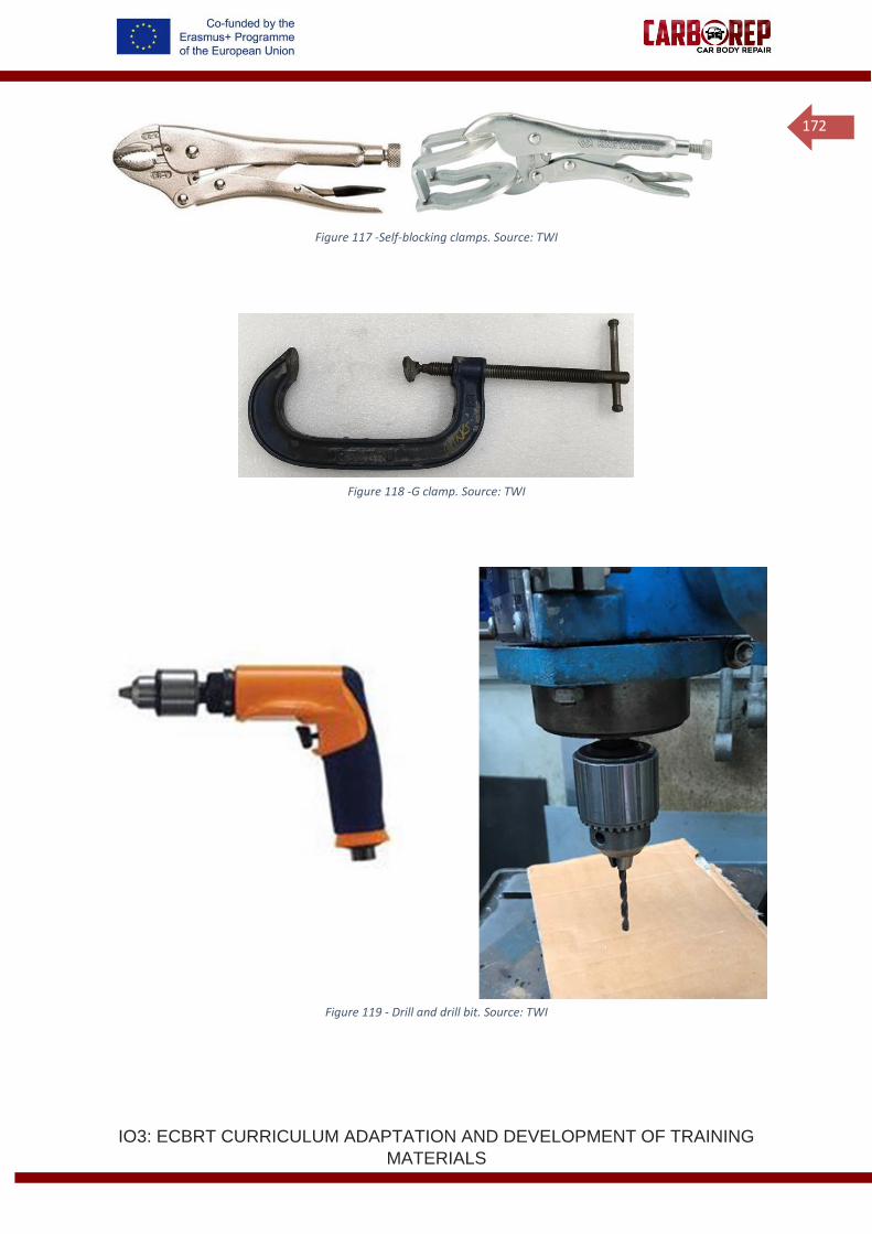
IO3: ECBRT CURRICULUM ADAPTATION AND DEVELOPMENT OF TRAINING
MATERIALS
172
Figure 117 -Self-blocking clamps. Source: TWI
Figure 118 -G clamp. Source: TWI
Figure 119 - Drill and drill bit. Source: TWI
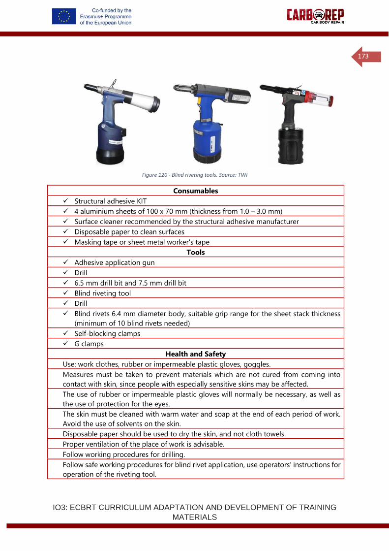
IO3: ECBRT CURRICULUM ADAPTATION AND DEVELOPMENT OF TRAINING
MATERIALS
173
Figure 120 - Blind riveting tools. Source: TWI
Consumables
✓ Structural adhesive KIT
✓ 4 aluminium sheets of 100 x 70 mm (thickness from 1.0 – 3.0 mm)
✓ Surface cleaner recommended by the structural adhesive manufacturer
✓ Disposable paper to clean surfaces
✓ Masking tape or sheet metal worker's tape
Tools
✓ Adhesive application gun
✓ Drill
✓ 6.5 mm drill bit and 7.5 mm drill bit
✓ Blind riveting tool
✓ Drill
✓ Blind rivets 6.4 mm diameter body, suitable grip range for the sheet stack thickness
(minimum of 10 blind rivets needed)
✓ Self-blocking clamps
✓ G clamps
Health and Safety
Use: work clothes, rubber or impermeable plastic gloves, goggles.
Measures must be taken to prevent materials which are not cured from coming into
contact with skin, since people with especially sensitive skins may be affected.
The use of rubber or impermeable plastic gloves will normally be necessary, as well as
the use of protection for the eyes.
The skin must be cleaned with warm water and soap at the end of each period of work.
Avoid the use of solvents on the skin.
Disposable paper should be used to dry the skin, and not cloth towels.
Proper ventilation of the place of work is advisable.
Follow working procedures for drilling.
Follow safe working procedures for blind rivet application, use operators’ instructions for
operation of the riveting tool.
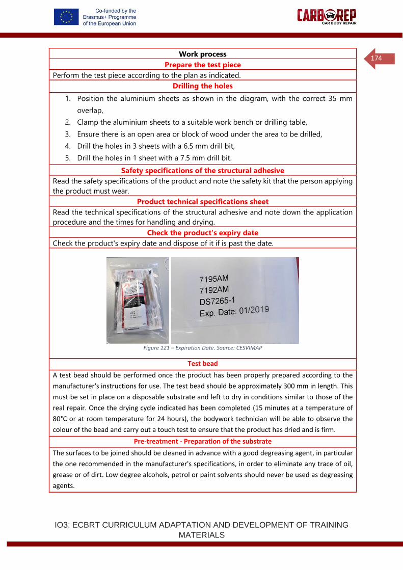
IO3: ECBRT CURRICULUM ADAPTATION AND DEVELOPMENT OF TRAINING
MATERIALS
174
Work process
Prepare the test piece
Perform the test piece according to the plan as indicated.
Drilling the holes
1. Position the aluminium sheets as shown in the diagram, with the correct 35 mm
overlap,
2. Clamp the aluminium sheets to a suitable work bench or drilling table,
3. Ensure there is an open area or block of wood under the area to be drilled,
4. Drill the holes in 3 sheets with a 6.5 mm drill bit,
5. Drill the holes in 1 sheet with a 7.5 mm drill bit.
Safety specifications of the structural adhesive
Read the safety specifications of the product and note the safety kit that the person applying
the product must wear.
Product technical specifications sheet
Read the technical specifications of the structural adhesive and note down the application
procedure and the times for handling and drying.
Check the product's expiry date
Check the product's expiry date and dispose of it if is past the date.
Figure 121 – Expiration Date. Source: CESVIMAP
Test bead
A test bead should be performed once the product has been properly prepared according to the
manufacturer's instructions for use. The test bead should be approximately 300 mm in length. This
must be set in place on a disposable substrate and left to dry in conditions similar to those of the
real repair. Once the drying cycle indicated has been completed (15 minutes at a temperature of
80°C or at room temperature for 24 hours), the bodywork technician will be able to observe the
colour of the bead and carry out a touch test to ensure that the product has dried and is firm.
Pre-treatment - Preparation of the substrate
The surfaces to be joined should be cleaned in advance with a good degreasing agent, in particular
the one recommended in the manufacturer's specifications, in order to eliminate any trace of oil,
grease or of dirt. Low degree alcohols, petrol or paint solvents should never be used as degreasing
agents.
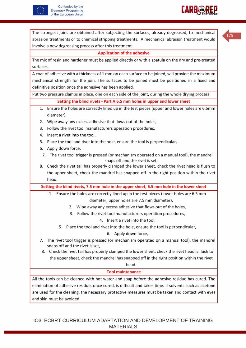
IO3: ECBRT CURRICULUM ADAPTATION AND DEVELOPMENT OF TRAINING
MATERIALS
175
The strongest joins are obtained after subjecting the surfaces, already degreased, to mechanical
abrasion treatments or to chemical stripping treatments. A mechanical abrasion treatment would
involve a new degreasing process after this treatment.
Application of the adhesive
The mix of resin and hardener must be applied directly or with a spatula on the dry and pre-treated
surfaces.
A coat of adhesive with a thickness of 1 mm on each surface to be joined, will provide the maximum
mechanical strength for the join. The surfaces to be joined must be positioned in a fixed and
definitive position once the adhesive has been applied.
Put two pressure clamps in place, one on each side of the joint, during the whole drying process.
Setting the blind rivets - Part A 6.5 mm holes in upper and lower sheet
1. Ensure the holes are correctly lined up in the test pieces (upper and lower holes are 6.5mm
diameter),
2. Wipe away any excess adhesive that flows out of the holes,
3. Follow the rivet tool manufacturers operation procedures,
4. Insert a rivet into the tool,
5. Place the tool and rivet into the hole, ensure the tool is perpendicular,
6. Apply down force,
7. The rivet tool trigger is pressed (or mechanism operated on a manual tool), the mandrel snaps off and the rivet is set,
8. Check the rivet tail has properly clamped the lower sheet, check the rivet head is flush to
the upper sheet, check the mandrel has snapped off in the right position within the rivet
head.
Setting the blind rivets, 7.5 mm hole in the upper sheet, 6.5 mm hole in the lower sheet
1. Ensure the holes are correctly lined up in the test pieces (lower holes are 6.5 mm
diameter; upper holes are 7.5 mm diameter),
2. Wipe away any excess adhesive that flows out of the holes,
3. Follow the rivet tool manufacturers operation procedures,
4. Insert a rivet into the tool,
5. Place the tool and rivet into the hole, ensure the tool is perpendicular,
6. Apply down force,
7. The rivet tool trigger is pressed (or mechanism operated on a manual tool), the mandrel snaps off and the rivet is set,
8. Check the rivet tail has properly clamped the lower sheet, check the rivet head is flush to
the upper sheet, check the mandrel has snapped off in the right position within the rivet
head.
Tool maintenance
All the tools can be cleaned with hot water and soap before the adhesive residue has cured. The
elimination of adhesive residue, once cured, is difficult and takes time. If solvents such as acetone
are used for the cleaning, the necessary protective measures must be taken and contact with eyes
and skin must be avoided.
IO3: ECBRT CURRICULUM ADAPTATION AND DEVELOPMENT OF TRAINING
MATERIALS
176
2.4 HYBRID JOINING IN ADHESIVE BONDING
2.4.1. Adhesive bonding and Resistance Spot Welding
The adhesive-welding joining technique combines the use of adhesives with resistance
spot welding and it is typically referred to as weld-bonding.
The effectiveness of the joint is much higher than when it is established by any of the
systems individually. A combined joint improves the distribution of the stresses and
the possibility of minimising fatigue problems, as well as allowing the adhesive to be
fixed in place until it cures.
The two techniques most frequently used are adhesive - spot welding, commonly
referred to as weld-bonding and adhesive – riveting, commonly referred to as riv-
bonding; the first is more common in steel vehicle bodies and the second in aluminium
bodies.
Many components in a steel vehicle are spot welded through an adhesive in the OEM’s
original production line. Most epoxy adhesives and sealants used in car body
applications are spot weldable. The usual order of process in the car body assembly
line is:
• Initial panel placement.
• Application of adhesive from dispensing system.
• Placement of second (and sometimes third) panel.
• Spot weld applied.
The electrode force when spot welding through an adhesive must be sufficient to
displace the adhesive under the electrode, in car body welding plants, forces greater
than 2kN (2000N or 200kg) are used. The adhesive formulation flows out of the area
under the electrode and allows the current to pass.

IO3: ECBRT CURRICULUM ADAPTATION AND DEVELOPMENT OF TRAINING
MATERIALS
177
The passage of current melts the steel and locally burns any remaining residues of the
adhesive. Fumes released from burned epoxy can be toxic, so extraction systems may
be used.
In general, little alteration to the spot welding program is required for welding through
an epoxy adhesive. However, if difficulties are faced in achieving an adequate quality
spot weld through an adhesive, the following actions can be taken:
• Increase the welding force: This helps to squeeze out the adhesive
allowing the welding current to flow as normal between the steel sheets.
• Increase the squeeze time: This allows a little more time to squeeze out
the adhesive prior to welding (weld time).
• Increase the weld time: A longer weld time allows a gentler rate of weld
growth, which can be more stable than rapid growth in a short time.
• Reduce the welding current: If splashing or expulsion is a problem when
welding through an adhesive, then the use of a lower current (often in
combination with increased force and increased weld time) can stabilise
the weld growth without overheating.
• Use a pre pulse current: Some welding equipment has the possibility to
program a ‘pre pulse’ current, which is a low current initial pulse, this can
be used to heat and soften the plates of material and warm the adhesive
to help it flow out of the joint area before the main welding current pulse
is applied.
It is very important to note that adhesives containing glass beads are not suitable for
spot welding.
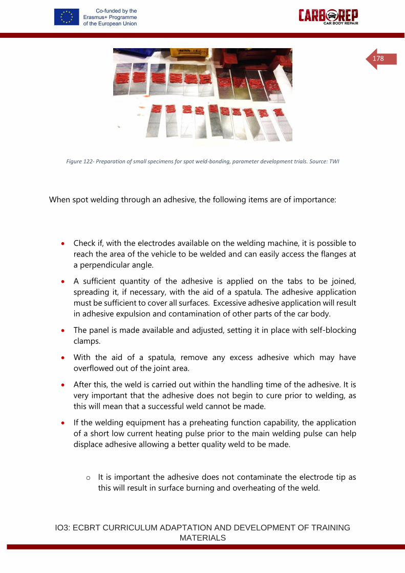
IO3: ECBRT CURRICULUM ADAPTATION AND DEVELOPMENT OF TRAINING
MATERIALS
178
Figure 122- Preparation of small specimens for spot weld-bonding, parameter development trials. Source: TWI
When spot welding through an adhesive, the following items are of importance:
• Check if, with the electrodes available on the welding machine, it is possible to
reach the area of the vehicle to be welded and can easily access the flanges at
a perpendicular angle.
• A sufficient quantity of the adhesive is applied on the tabs to be joined,
spreading it, if necessary, with the aid of a spatula. The adhesive application
must be sufficient to cover all surfaces. Excessive adhesive application will result
in adhesive expulsion and contamination of other parts of the car body.
• The panel is made available and adjusted, setting it in place with self-blocking
clamps.
• With the aid of a spatula, remove any excess adhesive which may have
overflowed out of the joint area.
• After this, the weld is carried out within the handling time of the adhesive. It is
very important that the adhesive does not begin to cure prior to welding, as
this will mean that a successful weld cannot be made.
• If the welding equipment has a preheating function capability, the application
of a short low current heating pulse prior to the main welding pulse can help
displace adhesive allowing a better quality weld to be made.
o It is important the adhesive does not contaminate the electrode tip as
this will result in surface burning and overheating of the weld.

IO3: ECBRT CURRICULUM ADAPTATION AND DEVELOPMENT OF TRAINING
MATERIALS
179
Operator Name: Date:
Welding machine: Standards / procedures followed:
Vehicle / component:
Material 1: Material 2: Material 3:
Electrode details Water cooling
Test piece dimensions: Weld pitch:
Adhesive used: Adhesive expiry date:
Squeeze time: Weld time: Hold time:
Electrode force / pressure: Transformer tap:
Weld number
Current (kA or
heat %)
Weld diameter d1 (mm)
Weld diameter d2 (mm)
Average diameter
d1+d2/2 (mm)
Weld splash
(expulsion)
Comments observations
Table 19- Example spot welding data sheet
2.4.3 Quality Control
Process to ensure quality control and join inspection (non-destructive tests such
as visual inspection)
There are a variety of possible faults in adhesive joins, cracks, fissures, discontinuities,
etc., due mainly to errors occurring during surface pre-treatment. Once the joint has
been designed and the adhesive has been applied, there are various control methods
to check the final quality, such as ultrasound, x-rays, acoustic signal, thermal or infrared
and thermographic inspection, seal quality, etc. Visual inspection is the technique most
used in bodywork bonding processes.
In the repair of automobile bodies where adhesive is involved, a check must be made
of the bonded area to see if:
a. The adhesive properly covers all the surfaces to be joined without leaving any
surface free of adhesive.
b. The curing of the adhesive has been correctly applied
IO3: ECBRT CURRICULUM ADAPTATION AND DEVELOPMENT OF TRAINING
MATERIALS
180
In order to ensure that these two parameters are correct the following checks must be
verified and undertaken:
1. After conducting an adhesive bond in combination with riveting or resistance
spot welding, a check must be made, to ensure that the adhesive overflows all
along the adhesive joined area.
a. A vehicle manufacturer will indicate in the repair shop manual for the
vehicle that surplus or overflowing adhesive should be removed from the
joint with the recommended consumables. Despite this warning, it is very
important for the adhesive to overflow all along the join, as this will be a
sign that the adhesive has reached all the surfaces to be joined. Correct
dosing during adhesive application is important.
2. Curing test bead
a. Before applying the adhesive on the surfaces to be joined, it is important
to carry out a curing test bead that meets the following characteristics
and performance procedure:
b. Once the structural adhesive cartridge has been prepared, and the
components of the adhesive have been pushed out through the
cartridge nozzle, the mixing nozzle is set in place, and a curing test bead
on a disposable substrate is produced. The test bead should be
approximately 300 mm in length. It must be placed on a disposable
substrate, and left to dry in conditions similar to those of the real repair.
In other words, if the joint is left to air dry, the test bead is left to air dry,
and if the joint is dried by forcing drying by means of heat, the test bead
should be placed in the vehicle and subjected to the same conditions of
curing by temperature as the vehicle.

IO3: ECBRT CURRICULUM ADAPTATION AND DEVELOPMENT OF TRAINING
MATERIALS
181
c. Once dried and cured, the bodywork repair technician will be able to
observe the colour of the bead (see the indications of the adhesives
manufacturer) and carry out a touch test to ensure that the product has
dried and is firm.
Work procedures
The work processes regularly used in bodywork repair are: replacement of bonded
windows, replacement of the metallic bodywork parts, plastics repairs, bonding of
small parts, etc.
Replacement of bodywork metallic parts
In the repair of accident-damaged vehicles, it is very common to replace one or more
of the components making up the vehicle body. These operations involve, on certain
occasions, laborious work and significant manipulations of zones of the bodywork,
excessively disproportionate in relation to the size of the damage needing to be
repaired.
Replacement of the bodywork by partial sections are operations that are performed
by all the automobile manufacturers; by performing these it is possible to preserve the
original performance of the vehicle to the maximum, maintaining, as far as possible,
the joints created during manufacture.
Among the main properties of adhesive bond are their suitability to join dissimilar
materials, since these joints do not alter or deform fine sheets of metals, as is the case
with welding. They also seal the joints and distribute out the forces uniformly. The
replacement of a roof in most cases has only one alternative, by means of adhesive.
When it is a matter of sticking one part to another the parts need to receive prior
treatment, in order to boost adherence.
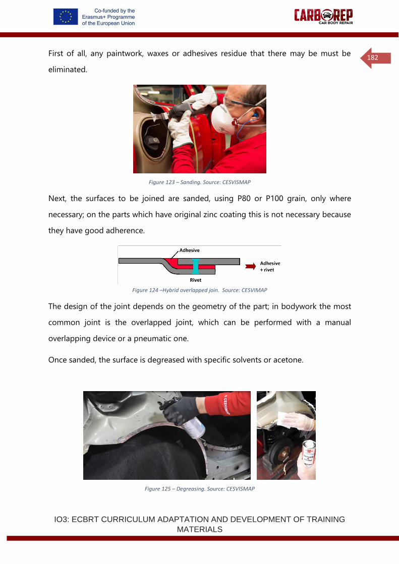
IO3: ECBRT CURRICULUM ADAPTATION AND DEVELOPMENT OF TRAINING
MATERIALS
182
First of all, any paintwork, waxes or adhesives residue that there may be must be
eliminated.
Figure 123 – Sanding. Source: CESVISMAP
Next, the surfaces to be joined are sanded, using P80 or P100 grain, only where
necessary; on the parts which have original zinc coating this is not necessary because
they have good adherence.
Figure 124 –Hybrid overlapped join. Source: CESVIMAP
The design of the joint depends on the geometry of the part; in bodywork the most
common joint is the overlapped joint, which can be performed with a manual
overlapping device or a pneumatic one.
Once sanded, the surface is degreased with specific solvents or acetone.
Figure 125 – Degreasing. Source: CESVISMAP
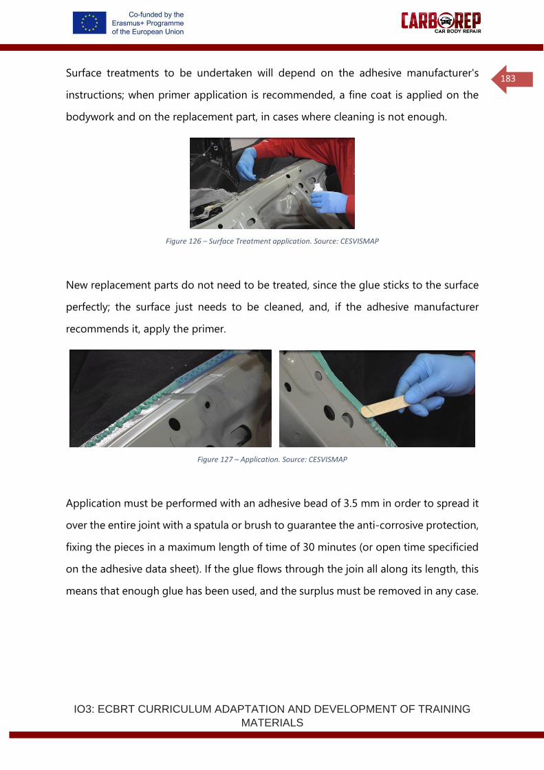
IO3: ECBRT CURRICULUM ADAPTATION AND DEVELOPMENT OF TRAINING
MATERIALS
183
Surface treatments to be undertaken will depend on the adhesive manufacturer's
instructions; when primer application is recommended, a fine coat is applied on the
bodywork and on the replacement part, in cases where cleaning is not enough.
Figure 126 – Surface Treatment application. Source: CESVISMAP
New replacement parts do not need to be treated, since the glue sticks to the surface
perfectly; the surface just needs to be cleaned, and, if the adhesive manufacturer
recommends it, apply the primer.
Figure 127 – Application. Source: CESVISMAP
Application must be performed with an adhesive bead of 3.5 mm in order to spread it
over the entire joint with a spatula or brush to guarantee the anti-corrosive protection,
fixing the pieces in a maximum length of time of 30 minutes (or open time specificied
on the adhesive data sheet). If the glue flows through the join all along its length, this
means that enough glue has been used, and the surplus must be removed in any case.
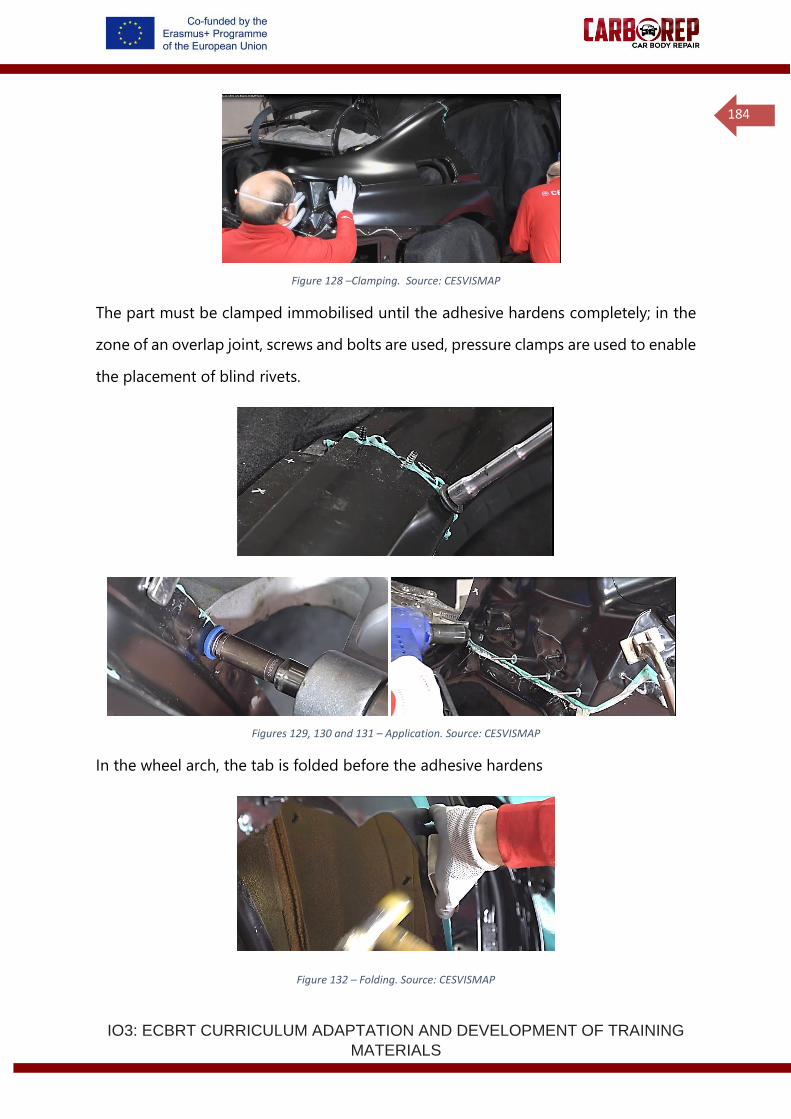
IO3: ECBRT CURRICULUM ADAPTATION AND DEVELOPMENT OF TRAINING
MATERIALS
184
Figure 128 –Clamping. Source: CESVISMAP
The part must be clamped immobilised until the adhesive hardens completely; in the
zone of an overlap joint, screws and bolts are used, pressure clamps are used to enable
the placement of blind rivets.
Figures 129, 130 and 131 – Application. Source: CESVISMAP
In the wheel arch, the tab is folded before the adhesive hardens
Figure 132 – Folding. Source: CESVISMAP
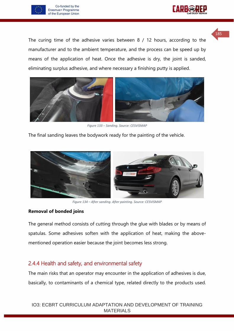
IO3: ECBRT CURRICULUM ADAPTATION AND DEVELOPMENT OF TRAINING
MATERIALS
185
The curing time of the adhesive varies between 8 / 12 hours, according to the
manufacturer and to the ambient temperature, and the process can be speed up by
means of the application of heat. Once the adhesive is dry, the joint is sanded,
eliminating surplus adhesive, and where necessary a finishing putty is applied.
Figure 133 – Sanding. Source: CESVISMAP
The final sanding leaves the bodywork ready for the painting of the vehicle.
Figure 134 – After sanding. After painting. Source: CESVISMAP
Removal of bonded joins
The general method consists of cutting through the glue with blades or by means of
spatulas. Some adhesives soften with the application of heat, making the above-
mentioned operation easier because the joint becomes less strong.
2.4.4 Health and safety, and environmental safety
The main risks that an operator may encounter in the application of adhesives is due,
basically, to contaminants of a chemical type, related directly to the products used.
IO3: ECBRT CURRICULUM ADAPTATION AND DEVELOPMENT OF TRAINING
MATERIALS
186
These may appear in the form of gases and vapours or in the form of liquids, and their
main paths of entry into the human body are the respiratory tracts and through the
skin.
Certain products used as curing agents for epoxy resins contain aliphatic amines, which
cause irritation to the skin, eyes and respiratory tracts, and can even cause asthma.
Polyurethanes are composed, in a large proportion, of isocyanates, which cause
mucous sensitivity and, to a lesser degree, cutaneous irritation and skin sensitivity.
The volatility of certain isocyanates increases with the reaction of polymerisation.
• Apply the products in premises fitted with good ventilation.
• Do not perform repairs close to flames or incandescent bodies, since certain
products are inflammable.
• Do not smoke during applications.
• Avoid bringing the products into contact with skin or eyes; to avoid this, safety
goggles and suitable gloves will be used.
• The respiratory tracts will have to be protected from the inhalation of vapours
or gases, using masks suitable for each use.
The measures for protection and for safety to be used in the replacement of vehicle
glass are:
• The risk of cuts with glass or with the tools must be prevented by the use of
work gloves.
• The treatment of waste must meet the regulation established in each country
and follow the recommendations of the adhesive manufacturer.
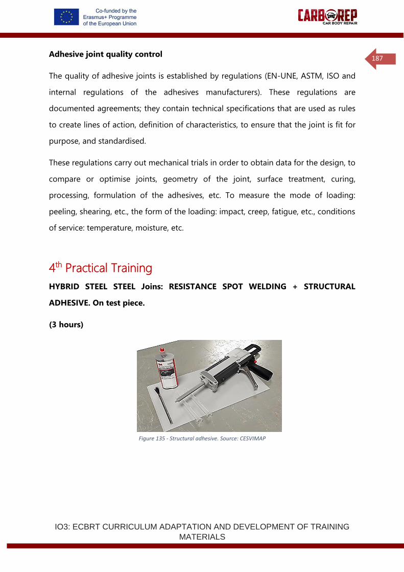
IO3: ECBRT CURRICULUM ADAPTATION AND DEVELOPMENT OF TRAINING
MATERIALS
187
Adhesive joint quality control
The quality of adhesive joints is established by regulations (EN-UNE, ASTM, ISO and
internal regulations of the adhesives manufacturers). These regulations are
documented agreements; they contain technical specifications that are used as rules
to create lines of action, definition of characteristics, to ensure that the joint is fit for
purpose, and standardised.
These regulations carry out mechanical trials in order to obtain data for the design, to
compare or optimise joints, geometry of the joint, surface treatment, curing,
processing, formulation of the adhesives, etc. To measure the mode of loading:
peeling, shearing, etc., the form of the loading: impact, creep, fatigue, etc., conditions
of service: temperature, moisture, etc.
4th Practical Training
HYBRID STEEL STEEL Joins: RESISTANCE SPOT WELDING + STRUCTURAL
ADHESIVE. On test piece.
(3 hours)
Figure 135 - Structural adhesive. Source: CESVIMAP
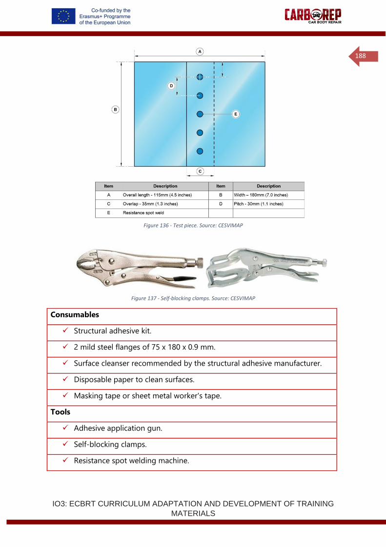
IO3: ECBRT CURRICULUM ADAPTATION AND DEVELOPMENT OF TRAINING
MATERIALS
188
Figure 136 - Test piece. Source: CESVIMAP
Figure 137 - Self-blocking clamps. Source: CESVIMAP
Consumables
✓ Structural adhesive kit.
✓ 2 mild steel flanges of 75 x 180 x 0.9 mm.
✓ Surface cleanser recommended by the structural adhesive manufacturer.
✓ Disposable paper to clean surfaces.
✓ Masking tape or sheet metal worker's tape.
Tools
✓ Adhesive application gun.
✓ Self-blocking clamps.
✓ Resistance spot welding machine.
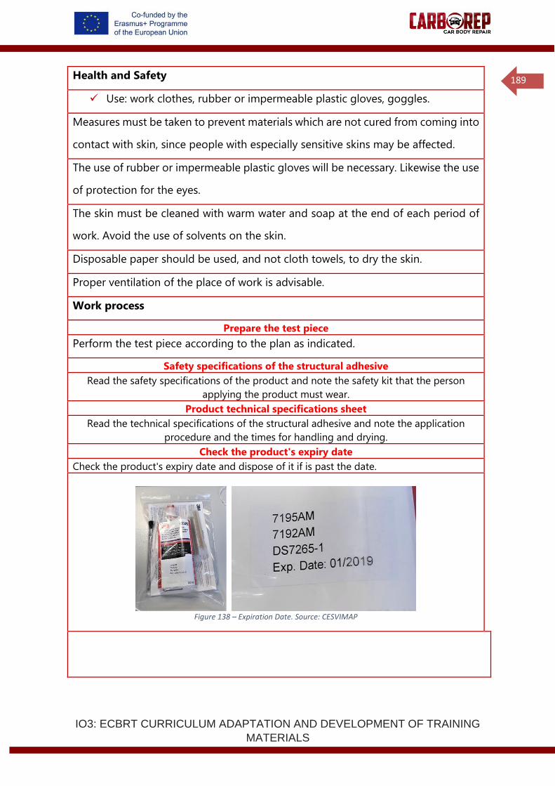
IO3: ECBRT CURRICULUM ADAPTATION AND DEVELOPMENT OF TRAINING
MATERIALS
189
Health and Safety
✓ Use: work clothes, rubber or impermeable plastic gloves, goggles.
Measures must be taken to prevent materials which are not cured from coming into
contact with skin, since people with especially sensitive skins may be affected.
The use of rubber or impermeable plastic gloves will be necessary. Likewise the use
of protection for the eyes.
The skin must be cleaned with warm water and soap at the end of each period of
work. Avoid the use of solvents on the skin.
Disposable paper should be used, and not cloth towels, to dry the skin.
Proper ventilation of the place of work is advisable.
Work process
Prepare the test piece
Perform the test piece according to the plan as indicated.
Safety specifications of the structural adhesive
Read the safety specifications of the product and note the safety kit that the person
applying the product must wear.
Product technical specifications sheet
Read the technical specifications of the structural adhesive and note the application
procedure and the times for handling and drying.
Check the product's expiry date
Check the product's expiry date and dispose of it if is past the date.
Figure 138 – Expiration Date. Source: CESVIMAP
IO3: ECBRT CURRICULUM ADAPTATION AND DEVELOPMENT OF TRAINING
MATERIALS
190
Test bead
A test bead should be performed once the product has been properly prepared
according to the manufacturer's instructions for use. The test bead should be
approximately 300 mm in length. This must be set in place on a disposable substrate
and left to dry in conditions similar to those of the real repair. Once the drying cycle
indicated has been completed (15 minutes at a temperature of 80°C or at room
temperature for 24 hours), the bodywork technician will be able to observe the colour
of the bead and carry out a touch test to ensure that the product has dried and is
firm.
Pre-treatment - Preparation of the substrate
The surfaces to be joined should be cleaned in advance with a good degreasing
agent, in particular the one recommended in the manufacturer's specifications, in
order to eliminate any trace of oil, grease or of dirt. Low degree alcohols, petrol or
paint solvents should never be used as degreasing agents.
The strongest joins are obtained after subjecting the surfaces, already degreased, to
mechanical abrasion treatments or to chemical stripping treatments. A mechanical
abrasion treatment would involve a new degreasing process after this treatment.
Application of the adhesive
The mix of resin and hardener must be applied directly or with a spatula on the dry,
pre-treated surfaces.
A coat of adhesive with a thickness of 1 mm on each surface to be joined, will provide
the maximum mechanical strength for the join. The surfaces to be joined must be
positioned in a fixed and definitive position once the adhesive has been applied.
Put two pressure clamps in place, one on each side of the join, during the whole
drying process.
Performing the resistance spot weld
Following the measurements of the test piece, perform the resistance spot weld
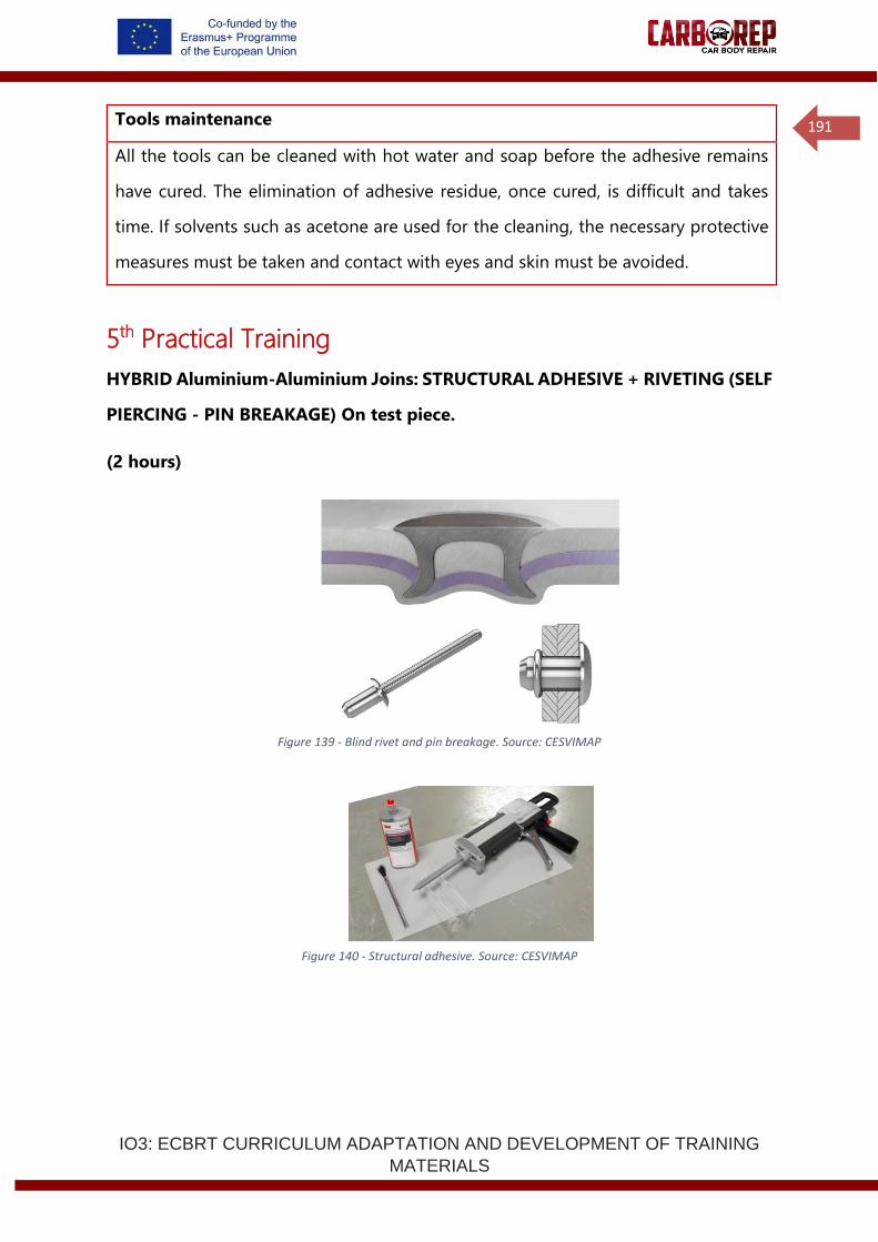
IO3: ECBRT CURRICULUM ADAPTATION AND DEVELOPMENT OF TRAINING
MATERIALS
191
Tools maintenance
All the tools can be cleaned with hot water and soap before the adhesive remains
have cured. The elimination of adhesive residue, once cured, is difficult and takes
time. If solvents such as acetone are used for the cleaning, the necessary protective
measures must be taken and contact with eyes and skin must be avoided.
5th Practical Training
HYBRID Aluminium-Aluminium Joins: STRUCTURAL ADHESIVE + RIVETING (SELF
PIERCING - PIN BREAKAGE) On test piece.
(2 hours)
Figure 139 - Blind rivet and pin breakage. Source: CESVIMAP
Figure 140 - Structural adhesive. Source: CESVIMAP
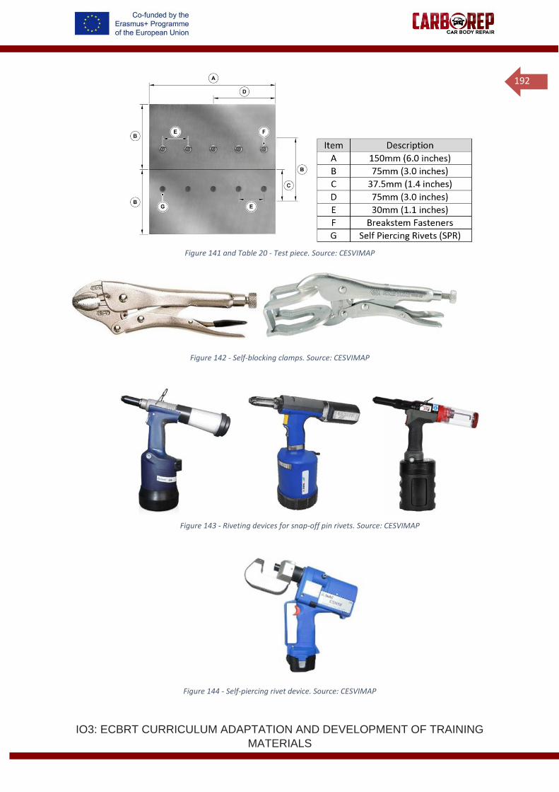
IO3: ECBRT CURRICULUM ADAPTATION AND DEVELOPMENT OF TRAINING
MATERIALS
192
Figure 141 and Table 20 - Test piece. Source: CESVIMAP
Figure 142 - Self-blocking clamps. Source: CESVIMAP
Figure 143 - Riveting devices for snap-off pin rivets. Source: CESVIMAP
Figure 144 - Self-piercing rivet device. Source: CESVIMAP
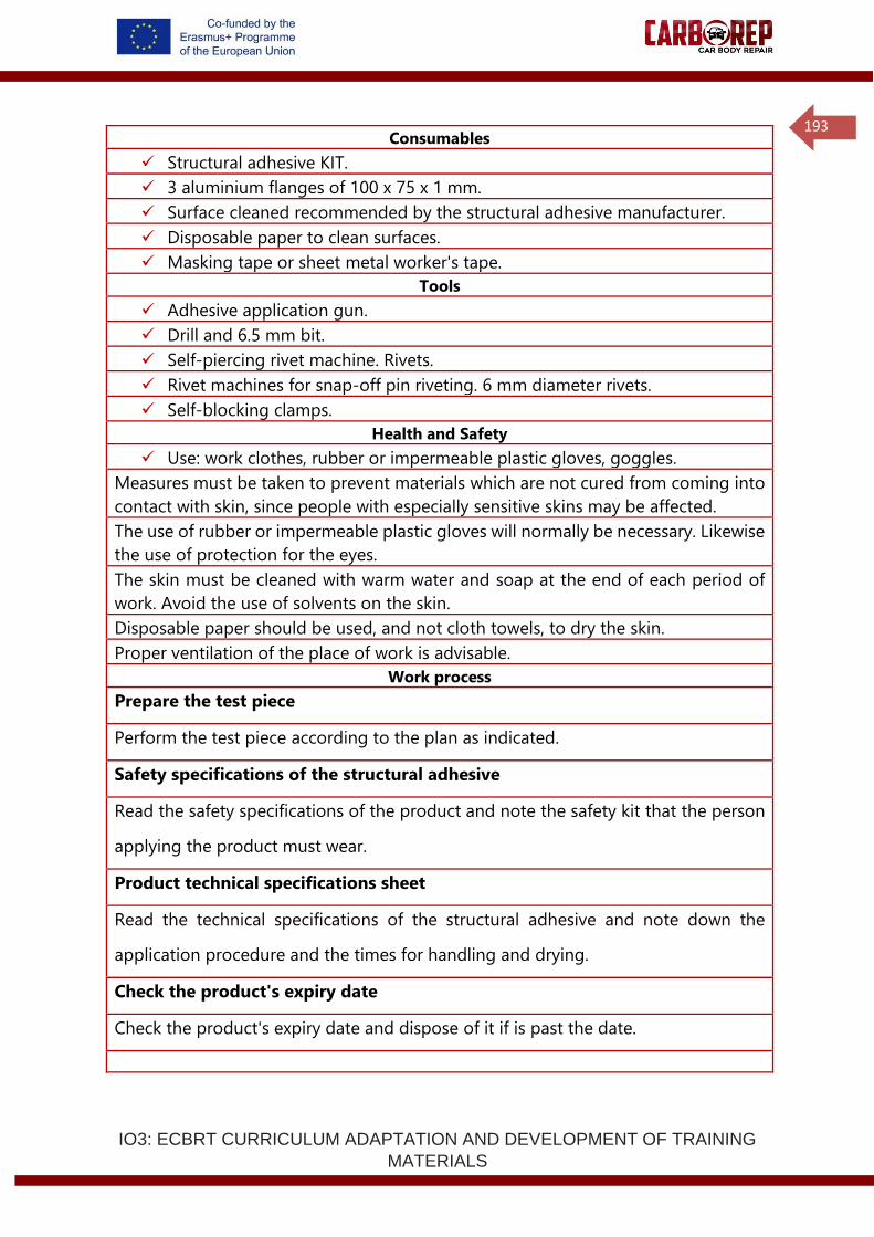
IO3: ECBRT CURRICULUM ADAPTATION AND DEVELOPMENT OF TRAINING
MATERIALS
193
Consumables
✓ Structural adhesive KIT.
✓ 3 aluminium flanges of 100 x 75 x 1 mm.
✓ Surface cleaned recommended by the structural adhesive manufacturer.
✓ Disposable paper to clean surfaces.
✓ Masking tape or sheet metal worker's tape.
Tools
✓ Adhesive application gun.
✓ Drill and 6.5 mm bit.
✓ Self-piercing rivet machine. Rivets.
✓ Rivet machines for snap-off pin riveting. 6 mm diameter rivets.
✓ Self-blocking clamps.
Health and Safety
✓ Use: work clothes, rubber or impermeable plastic gloves, goggles.
Measures must be taken to prevent materials which are not cured from coming into
contact with skin, since people with especially sensitive skins may be affected.
The use of rubber or impermeable plastic gloves will normally be necessary. Likewise
the use of protection for the eyes.
The skin must be cleaned with warm water and soap at the end of each period of
work. Avoid the use of solvents on the skin.
Disposable paper should be used, and not cloth towels, to dry the skin.
Proper ventilation of the place of work is advisable.
Work process
Prepare the test piece
Perform the test piece according to the plan as indicated.
Safety specifications of the structural adhesive
Read the safety specifications of the product and note the safety kit that the person
applying the product must wear.
Product technical specifications sheet
Read the technical specifications of the structural adhesive and note down the
application procedure and the times for handling and drying.
Check the product's expiry date
Check the product's expiry date and dispose of it if is past the date.
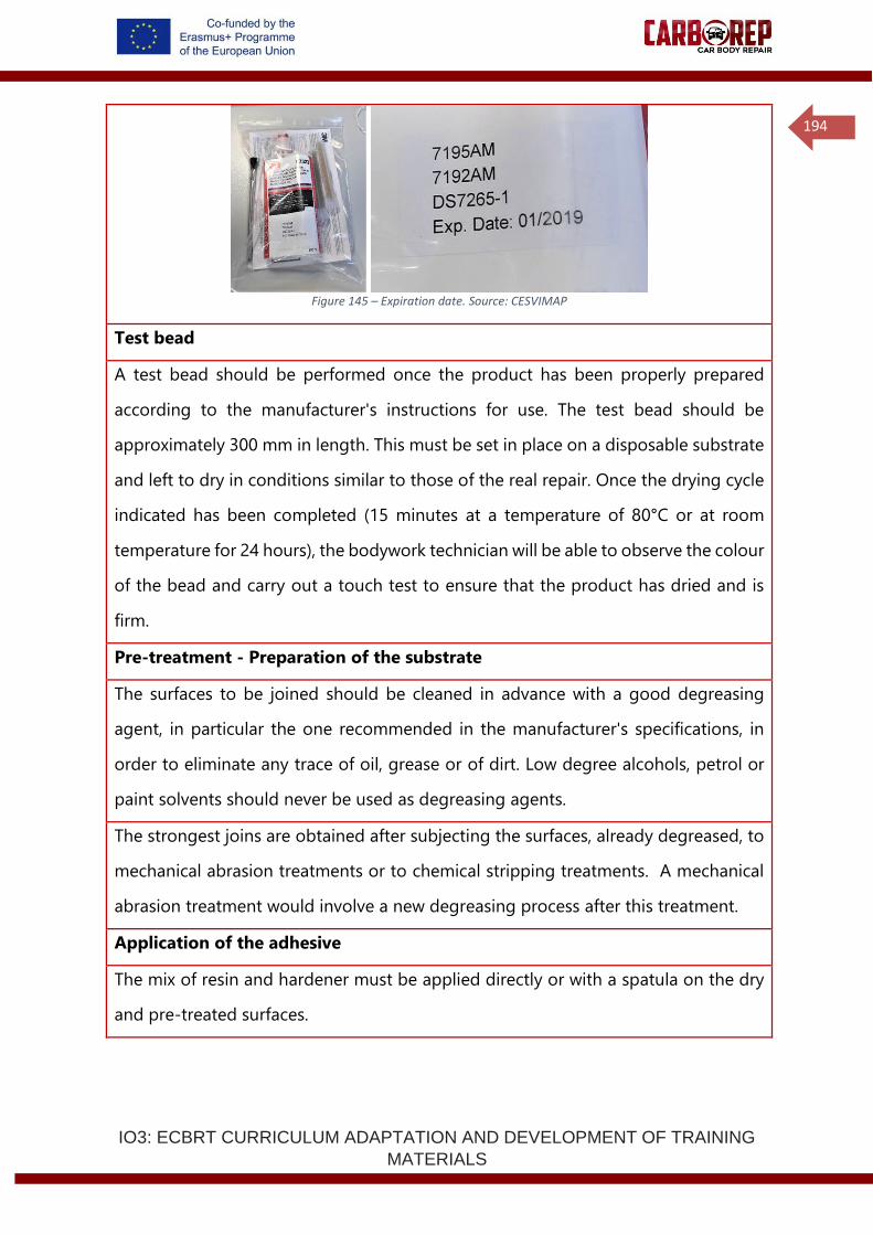
IO3: ECBRT CURRICULUM ADAPTATION AND DEVELOPMENT OF TRAINING
MATERIALS
194
Figure 145 – Expiration date. Source: CESVIMAP
Test bead
A test bead should be performed once the product has been properly prepared
according to the manufacturer's instructions for use. The test bead should be
approximately 300 mm in length. This must be set in place on a disposable substrate
and left to dry in conditions similar to those of the real repair. Once the drying cycle
indicated has been completed (15 minutes at a temperature of 80°C or at room
temperature for 24 hours), the bodywork technician will be able to observe the colour
of the bead and carry out a touch test to ensure that the product has dried and is
firm.
Pre-treatment - Preparation of the substrate
The surfaces to be joined should be cleaned in advance with a good degreasing
agent, in particular the one recommended in the manufacturer's specifications, in
order to eliminate any trace of oil, grease or of dirt. Low degree alcohols, petrol or
paint solvents should never be used as degreasing agents.
The strongest joins are obtained after subjecting the surfaces, already degreased, to
mechanical abrasion treatments or to chemical stripping treatments. A mechanical
abrasion treatment would involve a new degreasing process after this treatment.
Application of the adhesive
The mix of resin and hardener must be applied directly or with a spatula on the dry
and pre-treated surfaces.
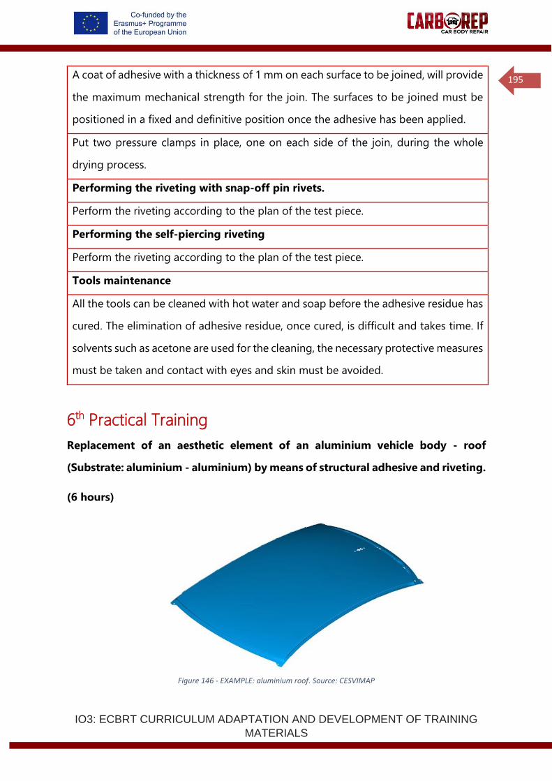
IO3: ECBRT CURRICULUM ADAPTATION AND DEVELOPMENT OF TRAINING
MATERIALS
195
A coat of adhesive with a thickness of 1 mm on each surface to be joined, will provide
the maximum mechanical strength for the join. The surfaces to be joined must be
positioned in a fixed and definitive position once the adhesive has been applied.
Put two pressure clamps in place, one on each side of the join, during the whole
drying process.
Performing the riveting with snap-off pin rivets.
Perform the riveting according to the plan of the test piece.
Performing the self-piercing riveting
Perform the riveting according to the plan of the test piece.
Tools maintenance
All the tools can be cleaned with hot water and soap before the adhesive residue has
cured. The elimination of adhesive residue, once cured, is difficult and takes time. If
solvents such as acetone are used for the cleaning, the necessary protective measures
must be taken and contact with eyes and skin must be avoided.
6th Practical Training
Replacement of an aesthetic element of an aluminium vehicle body - roof
(Substrate: aluminium - aluminium) by means of structural adhesive and riveting.
(6 hours)
Figure 146 - EXAMPLE: aluminium roof. Source: CESVIMAP
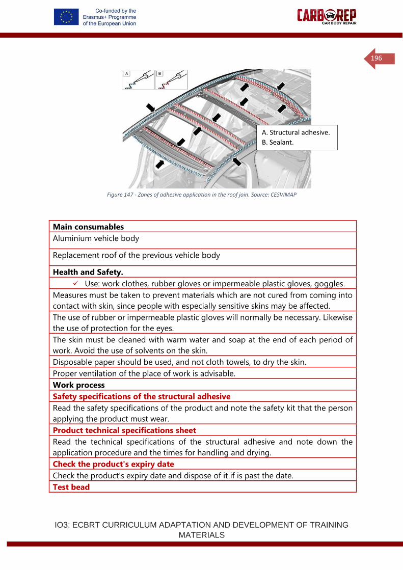
IO3: ECBRT CURRICULUM ADAPTATION AND DEVELOPMENT OF TRAINING
MATERIALS
196
Figure 147 - Zones of adhesive application in the roof join. Source: CESVIMAP
Main consumables
Aluminium vehicle body
Replacement roof of the previous vehicle body
Health and Safety.
✓ Use: work clothes, rubber gloves or impermeable plastic gloves, goggles.
Measures must be taken to prevent materials which are not cured from coming into
contact with skin, since people with especially sensitive skins may be affected.
The use of rubber or impermeable plastic gloves will normally be necessary. Likewise
the use of protection for the eyes.
The skin must be cleaned with warm water and soap at the end of each period of
work. Avoid the use of solvents on the skin.
Disposable paper should be used, and not cloth towels, to dry the skin.
Proper ventilation of the place of work is advisable.
Work process
Safety specifications of the structural adhesive
Read the safety specifications of the product and note the safety kit that the person
applying the product must wear.
Product technical specifications sheet
Read the technical specifications of the structural adhesive and note down the
application procedure and the times for handling and drying.
Check the product's expiry date
Check the product's expiry date and dispose of it if is past the date.
Test bead
A. Structural adhesive.
B. Sealant.
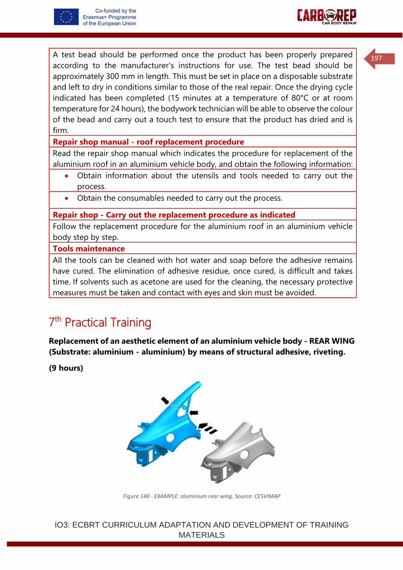
IO3: ECBRT CURRICULUM ADAPTATION AND DEVELOPMENT OF TRAINING
MATERIALS
197
A test bead should be performed once the product has been properly prepared
according to the manufacturer's instructions for use. The test bead should be
approximately 300 mm in length. This must be set in place on a disposable substrate
and left to dry in conditions similar to those of the real repair. Once the drying cycle
indicated has been completed (15 minutes at a temperature of 80°C or at room
temperature for 24 hours), the bodywork technician will be able to observe the colour
of the bead and carry out a touch test to ensure that the product has dried and is
firm.
Repair shop manual - roof replacement procedure
Read the repair shop manual which indicates the procedure for replacement of the
aluminium roof in an aluminium vehicle body, and obtain the following information:
• Obtain information about the utensils and tools needed to carry out the
process.
• Obtain the consumables needed to carry out the process.
Repair shop - Carry out the replacement procedure as indicated
Follow the replacement procedure for the aluminium roof in an aluminium vehicle
body step by step.
Tools maintenance
All the tools can be cleaned with hot water and soap before the adhesive remains
have cured. The elimination of adhesive residue, once cured, is difficult and takes
time. If solvents such as acetone are used for the cleaning, the necessary protective
measures must be taken and contact with eyes and skin must be avoided.
7th Practical Training
Replacement of an aesthetic element of an aluminium vehicle body - REAR WING
(Substrate: aluminium - aluminium) by means of structural adhesive, riveting.
(9 hours)
Figure 148 - EXAMPLE: aluminium rear wing. Source: CESVIMAP
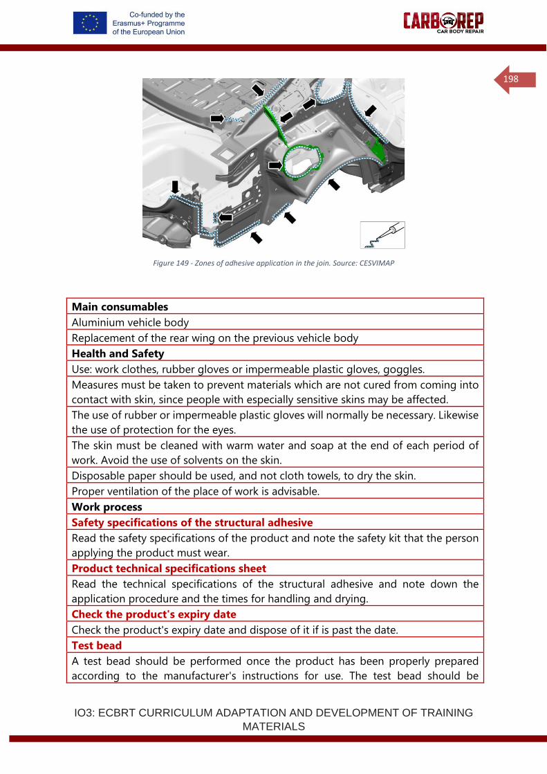
IO3: ECBRT CURRICULUM ADAPTATION AND DEVELOPMENT OF TRAINING
MATERIALS
198
Figure 149 - Zones of adhesive application in the join. Source: CESVIMAP
Main consumables
Aluminium vehicle body
Replacement of the rear wing on the previous vehicle body
Health and Safety
Use: work clothes, rubber gloves or impermeable plastic gloves, goggles.
Measures must be taken to prevent materials which are not cured from coming into
contact with skin, since people with especially sensitive skins may be affected.
The use of rubber or impermeable plastic gloves will normally be necessary. Likewise
the use of protection for the eyes.
The skin must be cleaned with warm water and soap at the end of each period of
work. Avoid the use of solvents on the skin.
Disposable paper should be used, and not cloth towels, to dry the skin.
Proper ventilation of the place of work is advisable.
Work process
Safety specifications of the structural adhesive
Read the safety specifications of the product and note the safety kit that the person
applying the product must wear.
Product technical specifications sheet
Read the technical specifications of the structural adhesive and note down the
application procedure and the times for handling and drying.
Check the product's expiry date
Check the product's expiry date and dispose of it if is past the date.
Test bead
A test bead should be performed once the product has been properly prepared
according to the manufacturer's instructions for use. The test bead should be
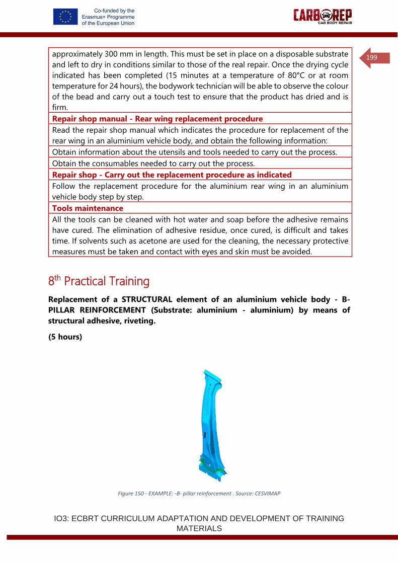
IO3: ECBRT CURRICULUM ADAPTATION AND DEVELOPMENT OF TRAINING
MATERIALS
199
approximately 300 mm in length. This must be set in place on a disposable substrate
and left to dry in conditions similar to those of the real repair. Once the drying cycle
indicated has been completed (15 minutes at a temperature of 80°C or at room
temperature for 24 hours), the bodywork technician will be able to observe the colour
of the bead and carry out a touch test to ensure that the product has dried and is
firm.
Repair shop manual - Rear wing replacement procedure
Read the repair shop manual which indicates the procedure for replacement of the
rear wing in an aluminium vehicle body, and obtain the following information:
Obtain information about the utensils and tools needed to carry out the process.
Obtain the consumables needed to carry out the process.
Repair shop - Carry out the replacement procedure as indicated
Follow the replacement procedure for the aluminium rear wing in an aluminium
vehicle body step by step.
Tools maintenance
All the tools can be cleaned with hot water and soap before the adhesive remains
have cured. The elimination of adhesive residue, once cured, is difficult and takes
time. If solvents such as acetone are used for the cleaning, the necessary protective
measures must be taken and contact with eyes and skin must be avoided.
8th Practical Training
Replacement of a STRUCTURAL element of an aluminium vehicle body - B-
PILLAR REINFORCEMENT (Substrate: aluminium - aluminium) by means of
structural adhesive, riveting.
(5 hours)
Figure 150 - EXAMPLE: -B- pillar reinforcement . Source: CESVIMAP

IO3: ECBRT CURRICULUM ADAPTATION AND DEVELOPMENT OF TRAINING
MATERIALS
200
Figure 151 - Zones of adhesive application in the join. Source: CESVIMAP
Main consumables
Aluminium vehicle body.
Replacement B-pillar reinforcement corresponding to the previous vehicle body.
Health and Safety
Use: work clothes, rubber gloves or impermeable plastic gloves, goggles.
Measures must be taken to prevent materials which are not cured from coming into
contact with skin, since people with especially sensitive skins may be affected.
The use of rubber or impermeable plastic gloves will normally be necessary. Likewise
the use of protection for the eyes.
The skin must be cleaned with warm water and soap at the end of each period of
work. Avoid the use of solvents on the skin.
Disposable paper should be used, and not cloth towels, to dry the skin.
Proper ventilation of the place of work is advisable.
Work process
Safety specifications of the structural adhesive
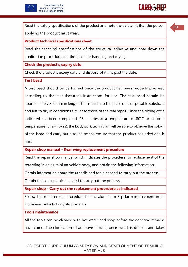
IO3: ECBRT CURRICULUM ADAPTATION AND DEVELOPMENT OF TRAINING
MATERIALS
201
Read the safety specifications of the product and note the safety kit that the person
applying the product must wear.
Product technical specifications sheet
Read the technical specifications of the structural adhesive and note down the
application procedure and the times for handling and drying.
Check the product's expiry date
Check the product's expiry date and dispose of it if is past the date.
Test bead
A test bead should be performed once the product has been properly prepared
according to the manufacturer's instructions for use. The test bead should be
approximately 300 mm in length. This must be set in place on a disposable substrate
and left to dry in conditions similar to those of the real repair. Once the drying cycle
indicated has been completed (15 minutes at a temperature of 80°C or at room
temperature for 24 hours), the bodywork technician will be able to observe the colour
of the bead and carry out a touch test to ensure that the product has dried and is
firm.
Repair shop manual - Rear wing replacement procedure
Read the repair shop manual which indicates the procedure for replacement of the
rear wing in an aluminium vehicle body, and obtain the following information:
Obtain information about the utensils and tools needed to carry out the process.
Obtain the consumables needed to carry out the process.
Repair shop - Carry out the replacement procedure as indicated
Follow the replacement procedure for the aluminium B-pillar reinforcement in an
aluminium vehicle body step by step.
Tools maintenance
All the tools can be cleaned with hot water and soap before the adhesive remains
have cured. The elimination of adhesive residue, once cured, is difficult and takes
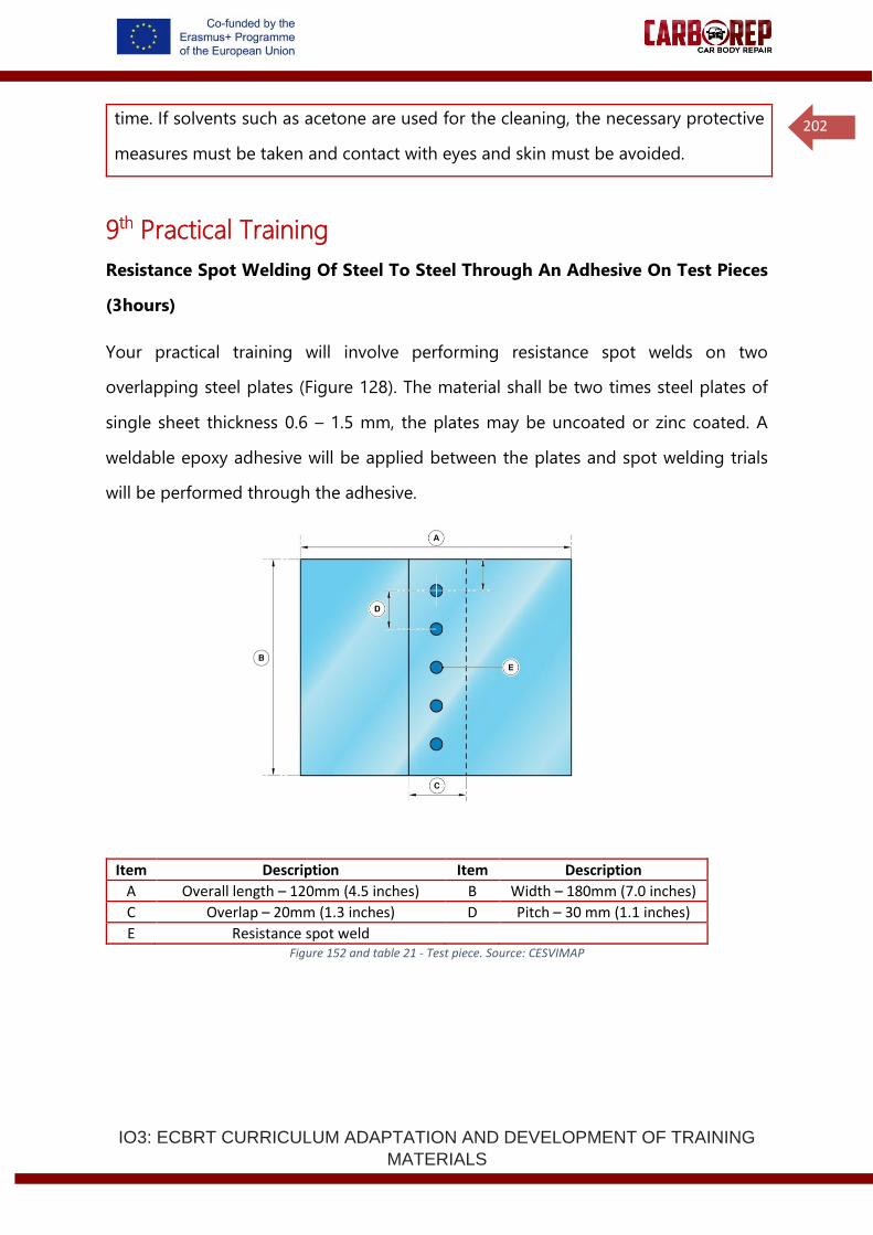
IO3: ECBRT CURRICULUM ADAPTATION AND DEVELOPMENT OF TRAINING
MATERIALS
202
time. If solvents such as acetone are used for the cleaning, the necessary protective
measures must be taken and contact with eyes and skin must be avoided.
9th Practical Training
Resistance Spot Welding Of Steel To Steel Through An Adhesive On Test Pieces
(3hours)
Your practical training will involve performing resistance spot welds on two
overlapping steel plates (Figure 128). The material shall be two times steel plates of
single sheet thickness 0.6 – 1.5 mm, the plates may be uncoated or zinc coated. A
weldable epoxy adhesive will be applied between the plates and spot welding trials
will be performed through the adhesive.
Item Description Item Description
A Overall length – 120mm (4.5 inches) B Width – 180mm (7.0 inches)
C Overlap – 20mm (1.3 inches) D Pitch – 30 mm (1.1 inches)
E Resistance spot weld Figure 152 and table 21 - Test piece. Source: CESVIMAP
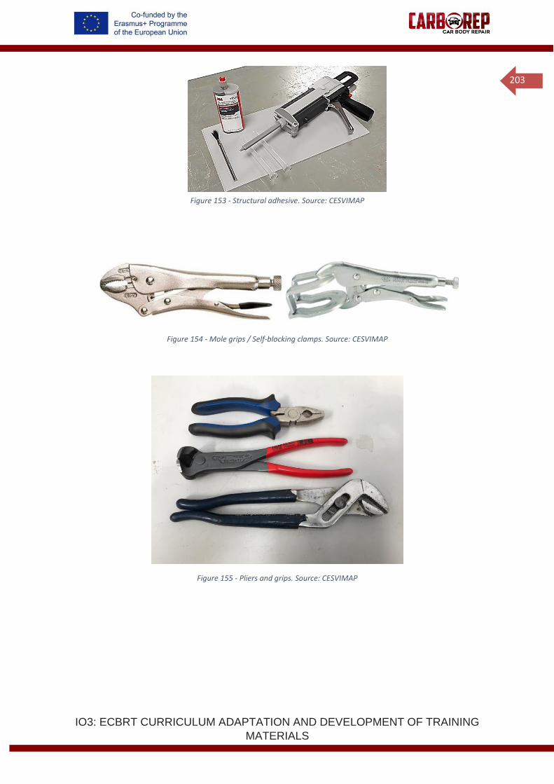
IO3: ECBRT CURRICULUM ADAPTATION AND DEVELOPMENT OF TRAINING
MATERIALS
203
Figure 153 - Structural adhesive. Source: CESVIMAP
Figure 154 - Mole grips / Self-blocking clamps. Source: CESVIMAP
Figure 155 - Pliers and grips. Source: CESVIMAP
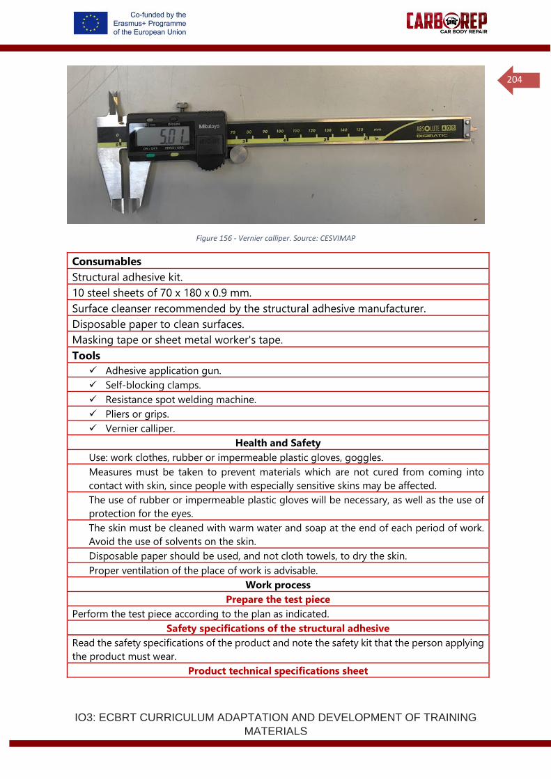
IO3: ECBRT CURRICULUM ADAPTATION AND DEVELOPMENT OF TRAINING
MATERIALS
204
Figure 156 - Vernier calliper. Source: CESVIMAP
Consumables
Structural adhesive kit.
10 steel sheets of 70 x 180 x 0.9 mm.
Surface cleanser recommended by the structural adhesive manufacturer.
Disposable paper to clean surfaces.
Masking tape or sheet metal worker's tape.
Tools
✓ Adhesive application gun.
✓ Self-blocking clamps.
✓ Resistance spot welding machine.
✓ Pliers or grips.
✓ Vernier calliper.
Health and Safety
Use: work clothes, rubber or impermeable plastic gloves, goggles.
Measures must be taken to prevent materials which are not cured from coming into
contact with skin, since people with especially sensitive skins may be affected.
The use of rubber or impermeable plastic gloves will be necessary, as well as the use of
protection for the eyes.
The skin must be cleaned with warm water and soap at the end of each period of work.
Avoid the use of solvents on the skin.
Disposable paper should be used, and not cloth towels, to dry the skin.
Proper ventilation of the place of work is advisable.
Work process
Prepare the test piece
Perform the test piece according to the plan as indicated.
Safety specifications of the structural adhesive
Read the safety specifications of the product and note the safety kit that the person applying
the product must wear.
Product technical specifications sheet
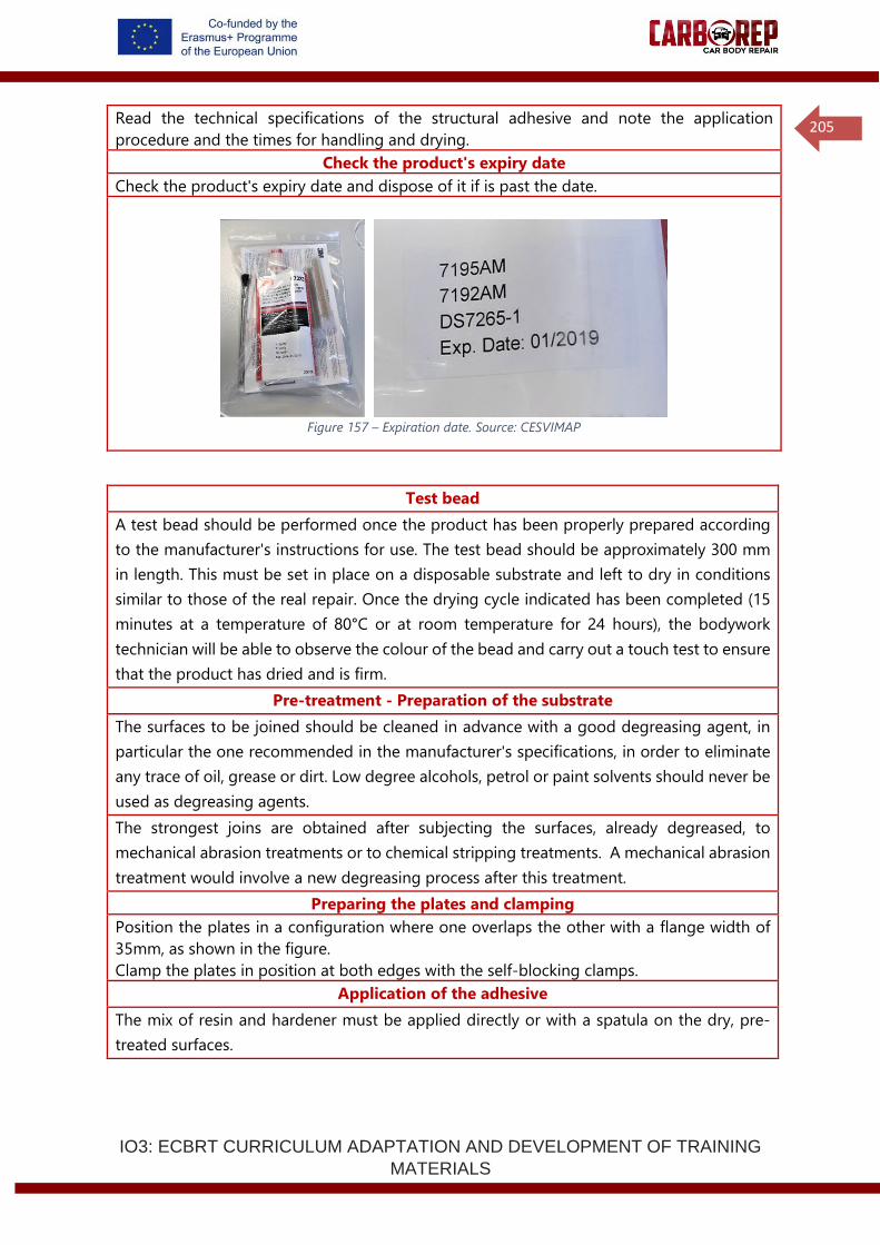
IO3: ECBRT CURRICULUM ADAPTATION AND DEVELOPMENT OF TRAINING
MATERIALS
205
Read the technical specifications of the structural adhesive and note the application
procedure and the times for handling and drying.
Check the product's expiry date
Check the product's expiry date and dispose of it if is past the date.
Figure 157 – Expiration date. Source: CESVIMAP
Test bead
A test bead should be performed once the product has been properly prepared according
to the manufacturer's instructions for use. The test bead should be approximately 300 mm
in length. This must be set in place on a disposable substrate and left to dry in conditions
similar to those of the real repair. Once the drying cycle indicated has been completed (15
minutes at a temperature of 80°C or at room temperature for 24 hours), the bodywork
technician will be able to observe the colour of the bead and carry out a touch test to ensure
that the product has dried and is firm.
Pre-treatment - Preparation of the substrate
The surfaces to be joined should be cleaned in advance with a good degreasing agent, in
particular the one recommended in the manufacturer's specifications, in order to eliminate
any trace of oil, grease or dirt. Low degree alcohols, petrol or paint solvents should never be
used as degreasing agents.
The strongest joins are obtained after subjecting the surfaces, already degreased, to
mechanical abrasion treatments or to chemical stripping treatments. A mechanical abrasion
treatment would involve a new degreasing process after this treatment.
Preparing the plates and clamping
Position the plates in a configuration where one overlaps the other with a flange width of
35mm, as shown in the figure.
Clamp the plates in position at both edges with the self-blocking clamps.
Application of the adhesive
The mix of resin and hardener must be applied directly or with a spatula on the dry, pre-
treated surfaces.
IO3: ECBRT CURRICULUM ADAPTATION AND DEVELOPMENT OF TRAINING
MATERIALS
206
A coat of adhesive with a thickness of 1 mm on each surface to be joined, will provide the
maximum mechanical strength for the join. The surfaces to be joined must be positioned in
a fixed and definitive position once the adhesive has been applied.
Put two pressure clamps in place, one on each side of the join, during the whole drying
process.
Setting up the resistance spot welding program
Following the measurements of the test piece, perform the resistance spot weld.
Select welding parameters according to an instruction or standard, initially select a low
current value or heat percentage.
Position the test piece between the electrodes and make the first weld.
If a weld splash occurs (liquid metal expulsion) reduce the welding current (or heat
percentage) by approximately 10% of the initial value.
Performing the spot welding test (Part A)
Record all parameters on a test sheet, as shown below:
1. Position the test piece between the electrodes and make the first weld (The distance
(pitch) between subsequent welds must be 30 mm).
2. If a weld splash occurs (liquid metal expulsion) reduce the welding current (or heat
%) by approximately 50% of the initial value.
3. If a weld is made without the occurrence of splash, increase current in small steps
(either 0.2kA or + 2.5% heat).
4. Continue increasing current in small steps and welding on test pieces until splash
occurs.
5. At the end of the test, hold one side of the test piece in a clamp and tear the other
side open using pliers or grips.
6. Measure the spot weld size with a Vernier calliper, as shown in the figure.
7. Record the largest and smallest diameter of the weld area and calculate the average;
record the data on the data sheet.
8. Check to see if the minimum weld size requirement could be met at a stable welding
condition before splash (liquid metal expulsion occurred).
9. At the end of welding, check the electrode condition for contamination by adhesive
(or excessive wear as a result of the zinc coating, if coated steel was used). If
necessary, repair the electrode surface with a tip dressing tool, or replace the
electrode with a new one.
Repeating the spot welding test (Part B- Increased force and weld time)
In Part A, a spot welding process window was defined for a fixed set of parameters.
In Part B, the spot welding parameters will be varied by selecting a weld time 200% of the
time used in part A and a weld force (pressure) 200% of the force used in part A.
1. Position the test piece between the electrodes and make the first weld (The distance
(pitch) between subsequent welds must be 30 mm).
2. If a weld splash occurs (liquid metal expulsion) reduce the welding current (or heat
percentage) by approximately 50% of the initial value.
3. If a weld is made without the occurrence of splash, increase current in small steps
(either 0.2kA or + 2.5% heat).
4. Continue increasing current in small steps and welding on test pieces until splash
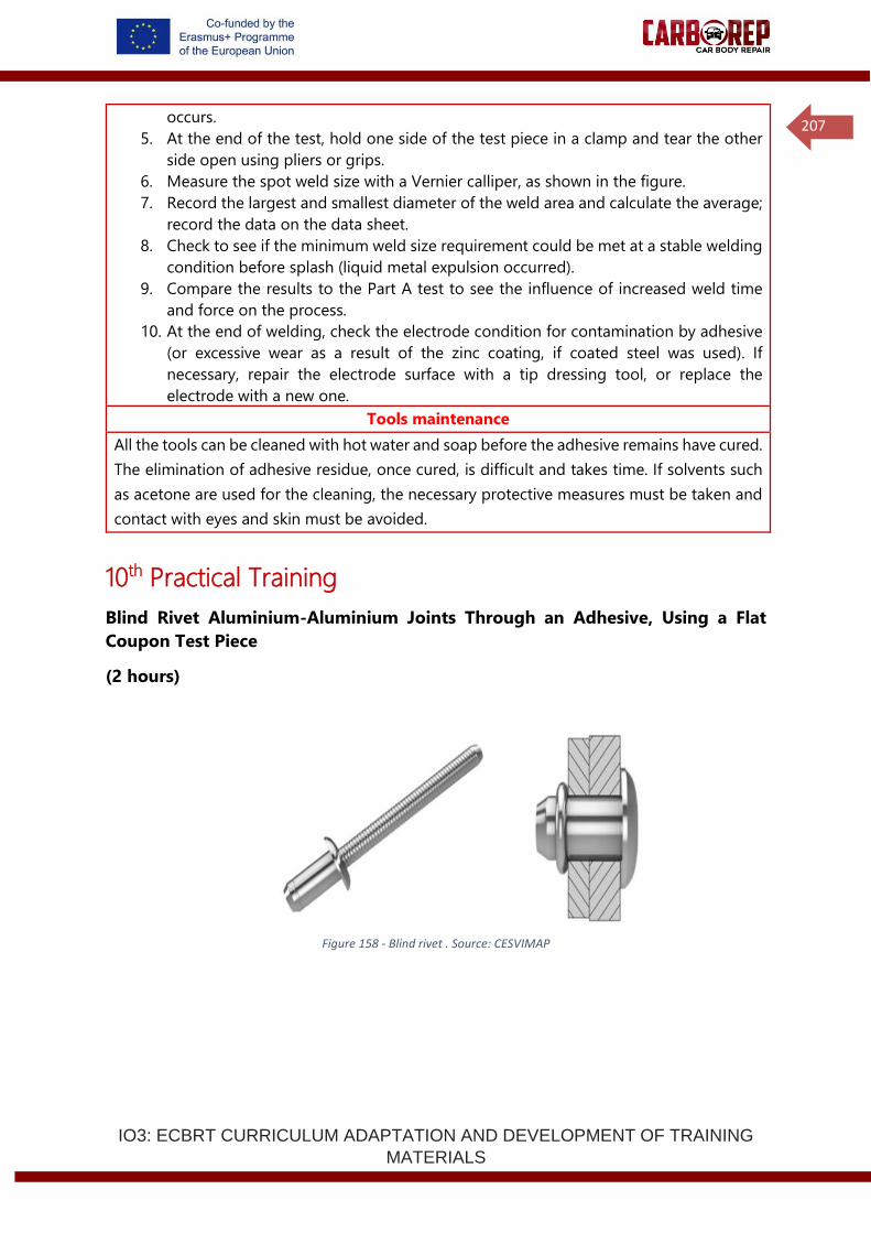
IO3: ECBRT CURRICULUM ADAPTATION AND DEVELOPMENT OF TRAINING
MATERIALS
207
occurs.
5. At the end of the test, hold one side of the test piece in a clamp and tear the other
side open using pliers or grips.
6. Measure the spot weld size with a Vernier calliper, as shown in the figure.
7. Record the largest and smallest diameter of the weld area and calculate the average;
record the data on the data sheet.
8. Check to see if the minimum weld size requirement could be met at a stable welding
condition before splash (liquid metal expulsion occurred).
9. Compare the results to the Part A test to see the influence of increased weld time
and force on the process.
10. At the end of welding, check the electrode condition for contamination by adhesive
(or excessive wear as a result of the zinc coating, if coated steel was used). If
necessary, repair the electrode surface with a tip dressing tool, or replace the
electrode with a new one.
Tools maintenance
All the tools can be cleaned with hot water and soap before the adhesive remains have cured.
The elimination of adhesive residue, once cured, is difficult and takes time. If solvents such
as acetone are used for the cleaning, the necessary protective measures must be taken and
contact with eyes and skin must be avoided.
10th Practical Training
Blind Rivet Aluminium-Aluminium Joints Through an Adhesive, Using a Flat
Coupon Test Piece
(2 hours)
Figure 158 - Blind rivet . Source: CESVIMAP
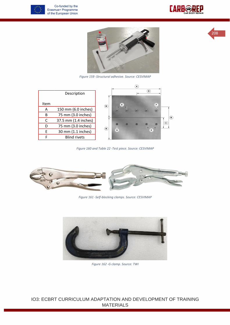
IO3: ECBRT CURRICULUM ADAPTATION AND DEVELOPMENT OF TRAINING
MATERIALS
208
Figure 159 -Structural adhesive. Source: CESVIMAP
Figure 160 and Table 22 -Test piece. Source: CESVIMAP
Figure 161 -Self-blocking clamps. Source: CESVIMAP
Figure 162 -G clamp. Source: TWI
Item
Description
A 150 mm (6.0 inches)
B 75 mm (3.0 inches)
C 37.5 mm (1.4 inches)
D 75 mm (3.0 inches)
E 30 mm (1.1 inches)
F Blind rivets
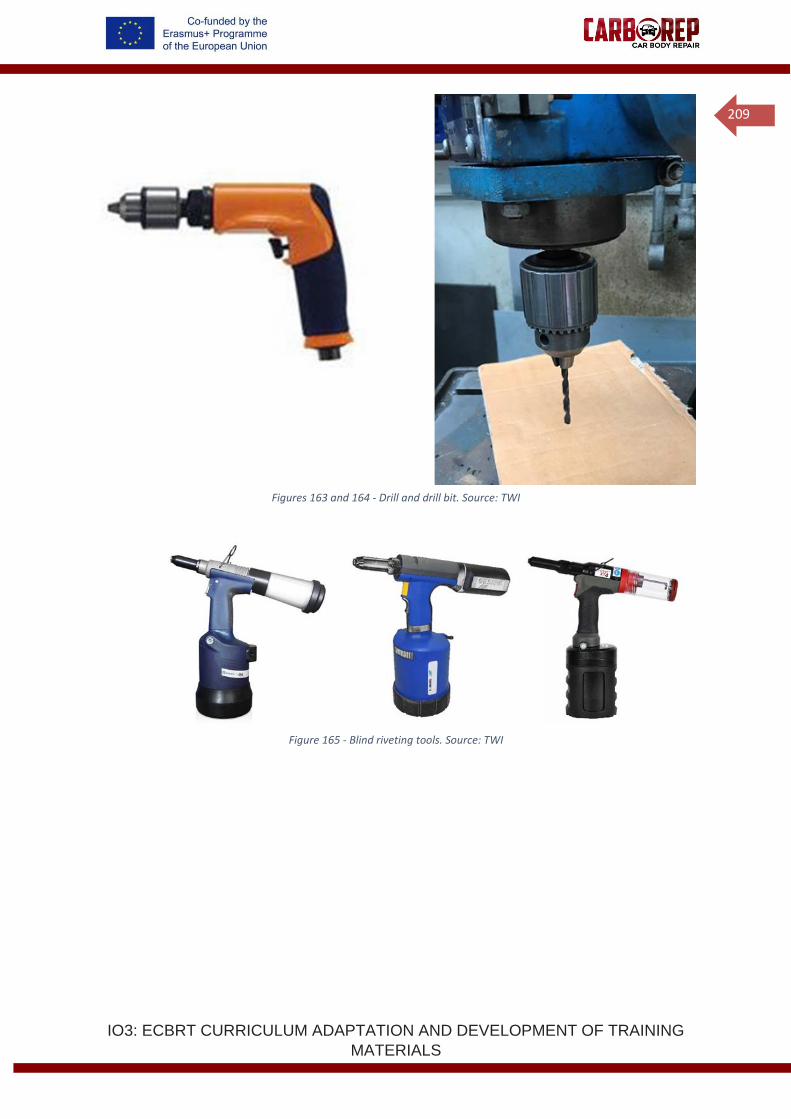
IO3: ECBRT CURRICULUM ADAPTATION AND DEVELOPMENT OF TRAINING
MATERIALS
209
Figures 163 and 164 - Drill and drill bit. Source: TWI
Figure 165 - Blind riveting tools. Source: TWI
IO3: ECBRT CURRICULUM ADAPTATION AND DEVELOPMENT OF TRAINING
MATERIALS
210
Consumables
✓ Structural adhesive KIT
✓ 4 aluminium sheets of 100 x 70 mm (thickness from 1.0 – 3.0 mm)
✓ Surface cleaner recommended by the structural adhesive manufacturer
✓ Disposable paper to clean surfaces
✓ Masking tape or sheet metal worker's tape
Tools
✓ Adhesive application gun
✓ Drill
✓ 6.5 mm drill bit and 7.5 mm drill bit
✓ Blind riveting tool
✓ Drill
✓ Blind rivets 6.4 mm diameter body, suitable grip range for the sheet stack thickness
(minimum of 10 blind rivets needed)
✓ Self-blocking clamps
✓ G clamps
Health and Safety
Use: work clothes, rubber or impermeable plastic gloves, goggles.
Measures must be taken to prevent materials which are not cured from coming into
contact with skin, since people with especially sensitive skins may be affected.
The use of rubber or impermeable plastic gloves will normally be necessary, as well as
the use of protection for the eyes.
The skin must be cleaned with warm water and soap at the end of each period of work.
Avoid the use of solvents on the skin.
Disposable paper should be used to dry the skin, and not cloth towels.
Proper ventilation of the place of work is advisable.
Follow working procedures for drilling.
Follow safe working procedures for blind rivet application, use operators’ instructions for
operation of the riveting tool.
Work process
Prepare the test piece
Perform the test piece according to the plan as indicated.
Drilling the holes
6. Position the aluminium sheets as shown in the diagram, with the correct 35 mm
overlap,
7. Clamp the aluminium sheets to a suitable work bench or drilling table,
8. Ensure there is an open area or block of wood under the area to be drilled,
9. Drill the holes in 3 sheets with a 6.5 mm drill bit,
10. Drill the holes in 1 sheet with a 7.5 mm drill bit.
Safety specifications of the structural adhesive
Read the safety specifications of the product and note the safety kit that the person applying
the product must wear.
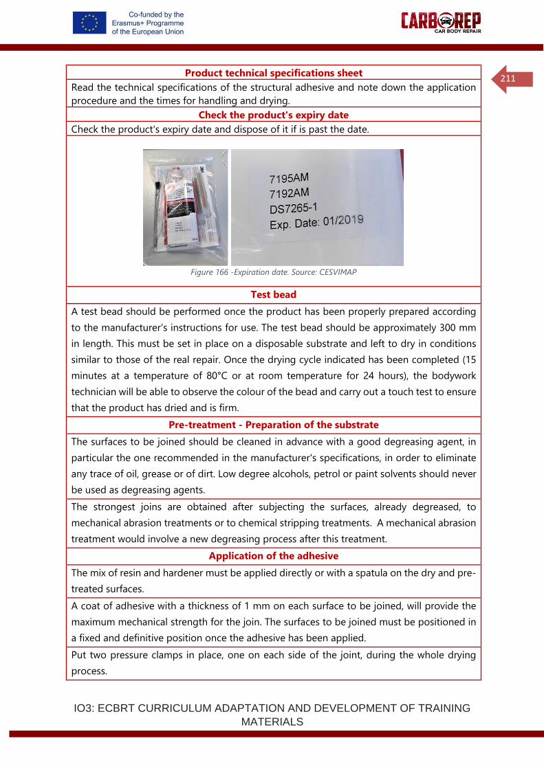
IO3: ECBRT CURRICULUM ADAPTATION AND DEVELOPMENT OF TRAINING
MATERIALS
211
Product technical specifications sheet
Read the technical specifications of the structural adhesive and note down the application
procedure and the times for handling and drying.
Check the product's expiry date
Check the product's expiry date and dispose of it if is past the date.
Figure 166 -Expiration date. Source: CESVIMAP
Test bead
A test bead should be performed once the product has been properly prepared according
to the manufacturer's instructions for use. The test bead should be approximately 300 mm
in length. This must be set in place on a disposable substrate and left to dry in conditions
similar to those of the real repair. Once the drying cycle indicated has been completed (15
minutes at a temperature of 80°C or at room temperature for 24 hours), the bodywork
technician will be able to observe the colour of the bead and carry out a touch test to ensure
that the product has dried and is firm.
Pre-treatment - Preparation of the substrate
The surfaces to be joined should be cleaned in advance with a good degreasing agent, in
particular the one recommended in the manufacturer's specifications, in order to eliminate
any trace of oil, grease or of dirt. Low degree alcohols, petrol or paint solvents should never
be used as degreasing agents.
The strongest joins are obtained after subjecting the surfaces, already degreased, to
mechanical abrasion treatments or to chemical stripping treatments. A mechanical abrasion
treatment would involve a new degreasing process after this treatment.
Application of the adhesive
The mix of resin and hardener must be applied directly or with a spatula on the dry and pre-
treated surfaces.
A coat of adhesive with a thickness of 1 mm on each surface to be joined, will provide the
maximum mechanical strength for the join. The surfaces to be joined must be positioned in
a fixed and definitive position once the adhesive has been applied.
Put two pressure clamps in place, one on each side of the joint, during the whole drying
process.
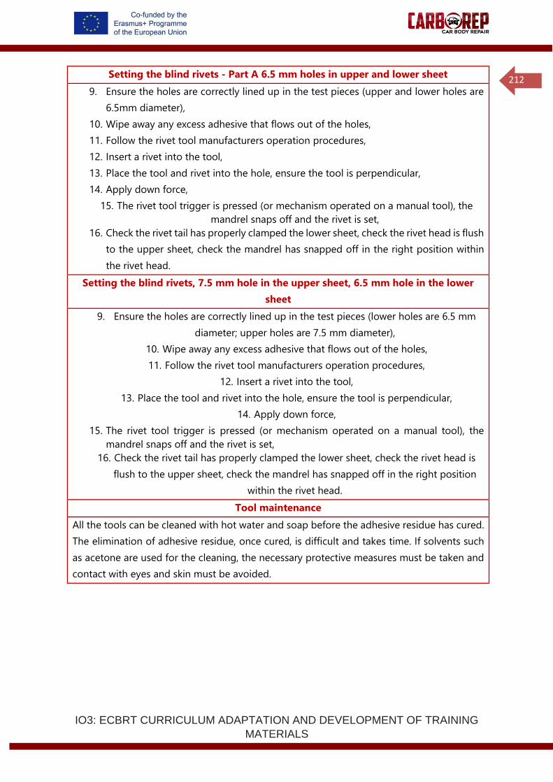
IO3: ECBRT CURRICULUM ADAPTATION AND DEVELOPMENT OF TRAINING
MATERIALS
212
Setting the blind rivets - Part A 6.5 mm holes in upper and lower sheet
9. Ensure the holes are correctly lined up in the test pieces (upper and lower holes are
6.5mm diameter),
10. Wipe away any excess adhesive that flows out of the holes,
11. Follow the rivet tool manufacturers operation procedures,
12. Insert a rivet into the tool,
13. Place the tool and rivet into the hole, ensure the tool is perpendicular,
14. Apply down force,
15. The rivet tool trigger is pressed (or mechanism operated on a manual tool), the
mandrel snaps off and the rivet is set,
16. Check the rivet tail has properly clamped the lower sheet, check the rivet head is flush
to the upper sheet, check the mandrel has snapped off in the right position within
the rivet head.
Setting the blind rivets, 7.5 mm hole in the upper sheet, 6.5 mm hole in the lower
sheet
9. Ensure the holes are correctly lined up in the test pieces (lower holes are 6.5 mm
diameter; upper holes are 7.5 mm diameter),
10. Wipe away any excess adhesive that flows out of the holes,
11. Follow the rivet tool manufacturers operation procedures,
12. Insert a rivet into the tool,
13. Place the tool and rivet into the hole, ensure the tool is perpendicular,
14. Apply down force,
15. The rivet tool trigger is pressed (or mechanism operated on a manual tool), the
mandrel snaps off and the rivet is set,
16. Check the rivet tail has properly clamped the lower sheet, check the rivet head is
flush to the upper sheet, check the mandrel has snapped off in the right position
within the rivet head.
Tool maintenance
All the tools can be cleaned with hot water and soap before the adhesive residue has cured.
The elimination of adhesive residue, once cured, is difficult and takes time. If solvents such
as acetone are used for the cleaning, the necessary protective measures must be taken and
contact with eyes and skin must be avoided.