training report on kalisindh super thermal power project, jhalawar
DESCRIPTION
“Every good work requires the guidance of some experts.” Many lives & destinies are destroyed due to the lack of proper guidance, directions & opportunities. It is in this respect I feel that I am in much better condition today due to continuous process of motivation & focus provided by my parents & teachers in general. The process of completion of this project was a tedious job & requires care & support at all stages. I would like to highlight the role played by individuals towards this. I oblige to acknowledge my heartiest gratitude to all honourable people who helped me during my summer training at KALISINDH THERMAL POWER PROJECT-JHALAWAR,(RRVUNL)RAJASTHAN. I want to express my thanks to Mr. S.S. Meena Chief Engineer KaTPP, Mr.S.N.Reja Project Incharge TCE Ltd. and Mr. Sunil Gangwal , G.M.(EE) BGR Energy System for granting me the permission for doing my summer training at this project And to give their valuable time and kind co-operation. I would like to thank Mr. S.N.Soni (X-En Elect-1), Mr. Raju (Tata Group),& Mr. B.B. Malav (A.En Elect-2) for providing the necessary guidance. I would like to Thank Mr. Lekhraj Meena (J.En,Elct-2, RRVUNL), Mr. Deepak Khndelwal (J.En,Elect-1, RRVUNL), Mr. Mithun Patidar (J.En,Elect-1, RRVUNL), & Mr.Raman Sir (J.En,TG Operation,BGR ENERGY SYSTEM) for providing me the knowledge about the work and giving their valuable guidance during my training period. I Would Co-Heartedly Thank And Use This Opportunity To Express Gratitude And Debtness To Mr.M.M.Sharma(Principal,Gecj), Mr. Neeraj Garg H.O.D. Electrical Engineering, Mr.Shrad Mahesvri & Mr. Nitin Arya, Placement Officer, T & P Cell, Govt Engineering College Jhalawar For Allowing Me To Do My Training At This Place. I am also thanks alot to other staff members of RRVUNL, BGR & TCE for their further co-operation to gain the better knowledge about the world class power plant project in distt –Jhalawar, Rajasthan. RADHEY SHYAM MEENATRANSCRIPT

1
TRAINING REPORT
KaTPP
(JHALAWAR)RRVUNL
SUBMITTED BYRADHEY SHYAM MEENA
B.TECH, ELECTRICAL ENGINEERINGGOVT ENGINEERING COLLEGE JHALAWAR, RAJASTHAN 326023
2
APRACTICAL TRAINING REPORT
ON
2 X 600 MW KALISINDH THERMAL POWERPROJECT, JHALAWAR
(RRVUNL)
SUBMITTEDIN PARTIAL FULFILMENT
FOR THE DEGREEBACHELOR OF TECHNOLOGY(B.TECH)
INELECTRICAL ENGINEERING
DEPT. OF ELECTRICAL ENGINEERINGGOVT ENGINEERING COLLEGE JHALAWAR
RAJASTHAN TECHNICAL UNIVERSITY KOTA
SUBMITTED BYRADHEY SHYAMMEENAB.TECH, FINAL YEAR
ENROLLMENT NO. 9E1EJEEM20P037MAY-JUNE 2012

3
PREFACE OF TRAINING
In today’s world, electricity has an important role. today, rely on electricity for the
fulfillment of even his basic needs comfortable living. Electricity contributes the largest
share to a country’s economic growth. It is the most powerful resource and has brought
industrial revolution world wide. It has resulted in social changes too and raised the
standard of living. In India, several organizations like NHPC, NTPC, POWER GRID,
and other state electricity boards etc. are engaged in electricity generation. RRVUNL is
one of the largest among these with an honourable Contribution.
The rise in civilization is closely related to improvements in transportation and
requirement of energy that is not readily available in large quantities but is also readily
transportable. There are several sourse of energy in world in which thermal power plant
is also a sourse of energy.It give electrical energy. A very peculiar fact about electrical
energy is that neither it is directly available in nature nor it is directly used finally in this
form, yet it is so widely produced and is the most popular high grade energy.
The purpose behind training is to understand the difficult concepts in a better
way with gain of knowledge. Report starts with a brief introduction of KaTPP.
While writing the report and while i was on my training i was wondering that
Science and technology are as ever expanding field and the engineers working hard day
and night and make the life a gift for us.
4
ACKNOWLEDGEMENT
“Every good work requires the guidance of some experts.”Many lives & destinies are destroyed due to the lack of proper guidance, directions &opportunities. It is in this respect I feel that I am in much better condition today due tocontinuous process of motivation & focus provided by my parents & teachers in general.The process of completion of this project was a tedious job & requires care & support atall stages. I would like to highlight the role played by individuals towards this.
I oblige to acknowledge my heartiest gratitude to all honourable people whohelped me during my summer training at KALISINDH THERMAL POWERPROJECT-JHALAWAR,(RRVUNL)RAJASTHAN.
I want to express my thanks to Mr. S.S. Meena Chief Engineer KaTPP,Mr.S.N.Reja Project Incharge TCE Ltd. and Mr. Sunil Gangwal , G.M.(EE) BGREnergy System for granting me the permission for doing my summer training at thisproject And to give their valuable time and kind co-operation.
I would like to thank Mr. S.N.Soni (X-En Elect-1), Mr. Raju (TataGroup),& Mr. B.B. Malav (A.En Elect-2) for providing the necessary guidance.
I would like to Thank Mr. Lekhraj Meena (J.En,Elct-2, RRVUNL), Mr.Deepak Khndelwal (J.En,Elect-1, RRVUNL), Mr. Mithun Patidar (J.En,Elect-1,RRVUNL), & Mr.Raman Sir (J.En,TG Operation,BGR ENERGY SYSTEM) forproviding me the knowledge about the work and giving their valuable guidance duringmy training period.
I Would Co-Heartedly Thank And Use This Opportunity To ExpressGratitude And Debtness To Mr.M.M.Sharma(Principal,Gecj), Mr. Neeraj GargH.O.D. Electrical Engineering, Mr.Shrad Mahesvri & Mr. Nitin Arya, PlacementOfficer, T & P Cell, Govt Engineering College Jhalawar For Allowing Me To DoMy Training At This Place.
I am also thanks alot to other staff members of RRVUNL, BGR & TCE fortheir further co-operation to gain the better knowledge about the world class powerplant project in distt –Jhalawar, Rajasthan.
RADHEY SHYAMMEENAB.TECH 4th YEAR
ELECTRICAL ENGINEERING

5

6
COLLEGE-CERTIFICATE
This is to certify that Mr. RADHEY SHYAM MEENA , B.Tech.(Electrical
Engineering) 4th year VII. semester has submitted His Training report entitled
“..2X600MW KALISINDH THERMAL POWER PROJECT
JHALAWAR(RAJASTHAN) RRVUNL..” under my/our guidance.Report submitted
by him is based on practical knowledge and as good as in my experience.
Mr.NEERAJ GARGASST.PROF. & H.O.D. ELECTRICAL ENGINEERING
Designation of Seminar Guide
7
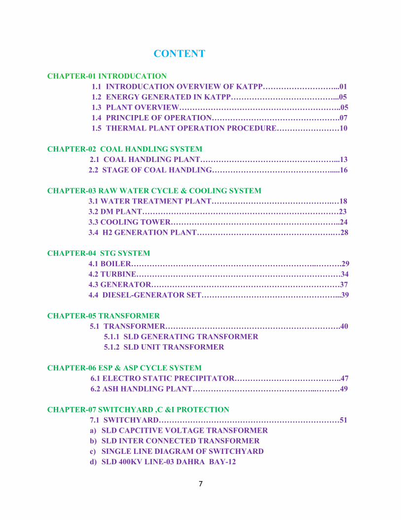
CONTENT
CHAPTER-01 INTRODUCATION1.1 INTRODUCATION OVERVIEW OF KATPP………………………...011.2 ENERGY GENERATED IN KATPP…………………………………...051.3 PLANT OVERVIEW……………………………………………………..051.4 PRINCIPLE OF OPERATION………………………………………….071.5 THERMAL PLANT OPERATION PROCEDURE……………………10
CHAPTER-02 COAL HANDLING SYSTEM2.1 COAL HANDLING PLANT……………………………………………...132.2 STAGE OF COAL HANDLING……………………………………….....16
CHAPTER-03 RAW WATER CYCLE & COOLING SYSTEM3.1 WATER TREATMENT PLANT……………………………………….…183.2 DM PLANT…………………………………………………………………233.3 COOLING TOWER………………………………………………………..243.4 H2 GENERATION PLANT…………………………………………….…28
CHAPTER-04 STG SYSTEM4.1 BOILER……………………………………………………………..……….294.2 TURBINE……………………………………………………………………344.3 GENERATOR………………………………………………………………374.4 DIESEL-GENERATOR SET……………………………………………...39
CHAPTER-05 TRANSFORMER5.1 TRANSFORMER………………………………………………………….40
5.1.1 SLD GENERATING TRANSFORMER5.1.2 SLD UNIT TRANSFORMER
CHAPTER-06 ESP & ASP CYCLE SYSTEM6.1 ELECTRO STATIC PRECIPITATOR…………………………………..476.2 ASH HANDLING PLANT………………………………………...………49
CHAPTER-07 SWITCHYARD ,C &I PROTECTION7.1 SWITCHYARD……………………………………………………………51a) SLD CAPCITIVE VOLTAGE TRANSFORMERb) SLD INTER CONNECTED TRANSFORMERc) SINGLE LINE DIAGRAM OF SWITCHYARDd) SLD 400KV LINE-03 DAHRA BAY-12

8
e) SLD 400KV LINE-01 BATAWDA BAY-05f) SLD 400KV LINE-02 BATAWDA BAY-09g) SLD 400KV SPARE LINE BAY-01h) SLD 400KV TIE LINE BAY-02i) SLD 400KV ICT LINE BAY-03j) SLD 220KV LINE-01 JHALAWAR BAY-01k) SLD 220KV LINE-02 JHALAWAR BAY-03l) SLD 220KV ICT LINE BAY-02m) SLD 220KV BUS COUPLER BAY-05n) SLD 220KV TRANSFER COUPLER BAY-047.2 SWITCHGEAR……………………………………………………………777.3 PROTECTION……………………………………………………………..797.4 CONTROL ROOM………………………….………………………...……817.5 AUXILLARY SUPPLY………………….…………………………………82
CHAPTER-08 EFFICIENCY8.1 POWER PLANT EFFICIENCY CALCULATION…..………………….858.2CONCLUSION………………...…………………………………..………..87
CHAPTER-07REFERENCE/BIBLIOGRAPHY-……………………………………………………….…88
APPENDICES:--
APPENDIX-I- PLANT LOCTED IN RAJASTHANAPPENDIX-II- POWER DISTRIBUTION MAP OF RAJASTHANAPPENDIX-III-KaTPP PLAN MAPAPPENDIX-IV-KaTPP SWITCHYARD PLAN MAP

9
LIST OF FIGURES
1. KaTPP PROJECT & PLANT OVERVIEW2
2. PLANT RUNNING VIEW7
3. RANKING CYCLE8
4. ENERGY CYCLE9
5. COAL CYCLE & COAL PROCESS 14-15
6. WATER TREATMENT PROCESS 21-22
7. COOLING TOWER24
8. FLOW OF WATER &KaTPP BOILER32
9. TURBINE & HP/ LP/ IP36
10. GENERATOR37
11. STEAM OVERVIEW39
12. GT/UT/UAT43
13. ASH HANDLING PLANT50
14. SWITCHYARD52
15. CIRCUIT BREAKER54
16. LIGHTING ARRESTER57
17. EARTHING ISOLATOR58
18. CURRENT TRANSFORMER59
19. CVT60
20. ICT64
21. CONTROL ROOM81

10
LIST OF TABLE
1.PLANT REPORT 05
2. IMPORTANT DATE 06
3. BOILER MOTOR DATA SHEET 31
4. TURBINE DATA SHEET 35
5.GENERATOR DATA SHEET 38
6.DG SAT DATA SHEET 39
7.GENERATING TRANSFORMER DATA SHEET 41
8. UNIT TRANSFORMER DATA SHEET 44
9.PARAMETER FOR CIRCUIT BREAKER 55-56
10 ISOLATOR PARAMETER 57
11 LIGHTING ARRESTER SHEET 58
12 CURRENT TRANSFORMER 59
13 CAPACITOR VOLTAGE TRANSFORMER 60-61
14.INTER CONNECTED TRANSFORMER 63

11
SINGLE LINE DIAGRAM
1. GENERATING TRANSFORMER 422. UNIT TRANSFORMER 453. CVT 624. ICT 655. 400KV LINE-03 DAHRA BAY-12 666. 400KV LINE-01 BATAWDA BAY-05 677. 400KV LINE-02 BTAWDA BAY-09 688. 400KV SPARE LINE BAY-01 699. 400KV TIE LINE BAY-02 7010. 400KV ICT LINE BAY-03 7111. 220KV LINE-01 JHALAWAR BAY-01 7212. 220KV LINE -02 JHALAWAR BAY -03 7313. 22KV ICT BAY-02 7414. 220KV BUS COUPLER BAY-05 7515. 220KV TRANSFER COUPLER BAY-04 76

1
CHAPTER-01 INTRODUCATION
Everybody must be having a thought that a thermal power plant is a place where electricity isproduced. But do you know how it is produced? The chemical energy stored is converted to heatenergy which forms the input of power plant and electrical energy produced by the generator isthe output. Power is the single most important necessity for the common people and industrial
development of a nation. In a convectional power plant the energy is first converted to amechanical work and then is converted to electrical energy. Thus the energy conversions
involved are:
The first energy conversion takes in what is called a Boiler or Steam Generator, the second inwhat is called a Turbine and the last conversion takes place in the Generator.
A thermal power station is a power plant in which the prime mover is steam driven. Water is
heated, turns into steam and spins a steam turbine which drives an electrical generator after it
passes through the turbine, the steam is condensed in a condenser and recycled to where it
was heated; this is known as a rankine cycle.
Commercial electric utility power stations are usually constructed on a large scale and
designed for continuous operation. Electric power plants typically use three-
phase electrical generators to produce alternating current (ac) electric power at
a frequency of 50hz.

13
1.1 INTRODUCATION
KaTPP
14
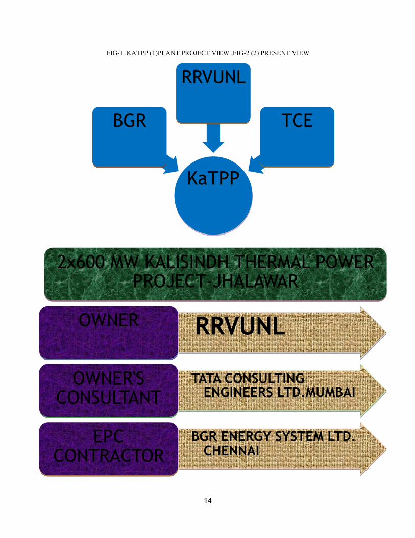
FIG-1 .KATPP (1)PLANT PROJECT VIEW ,FIG-2 (2) PRESENT VIEW
KaTPP
BGR
RRVUNL
TCE
2x600 MW KALISINDH THERMAL POWERPROJECT-JHALAWAR
RRVUNLOWNER
TATA CONSULTINGENGINEERS LTD.MUMBAI
OWNER'SCONSULTANT
BGR ENERGY SYSTEM LTD.CHENNAI
EPCCONTRACTOR

15
The site of Kalisindh Thermal Power Project is located in Nimoda, Undal, Motipura,
Singhania and Devri villages of Tehsil Jhalarapatan, Distt. Jhalawar. The proposed
capacity of coal based Thermal Power Project is 1200 MW. The project site is about
12 km from Jhalawar (Distt. Head quarter ) and NH-12 .It is 2km from state highway
No.19 and 8 km from proposed Ramganj Mandi - Bhopal broad gauge rail line.
The site selection committee of Central Electricity Authority has visited the
Nimodha and its adjoining villages of Jhalawar Distt. And site was found techno-
economical feasible for setting up of a Power Project. The Govt. of Raj. have included
that project in 11 th five year plan. The estimated revised cost of the project is
Rs.7723 Crores. M/s. TCE Banglore has been appointed as the technical consultant
for the project. The state irrigation department has alloted 1200 mcft water for the
project from proposed Kalisindh dam. The origin of the Kalisindh river is from northern
slop of Vindya Mountains . The river enters from MP to Rajasthan near village Binda.
After flowing 145 km in Rajasthan, the Kalisindh river merges in Chambal river near
Nanera village of Distt. Kota.Its catchment area is about 7944 sq.km in Jhalawar &
Kota Distt. The existing Dam is located at Bhawarasa village, primarily for P.H.E.D.
purpose is being uplifted for providing a storase of 1200mcft water for this power
project.
The GOR has alloted 842 bigha Government land and aquired 1388 bigha
private khatedari land for the thermal project .Phase-1 will be constructed on 1400
bigha land only.EPC contract has been awarded to M/s. BGR Energy System
Chennai on dt.09/07/08, through ICB route at cost Rs.4900 Crores. Ministry of coal,
Govt. of India has alloted ‘Paras east and Kanta basin ‘ coal blocks to RVUN in
Chhatisgarh state. The RVUN has formed new company under joined venture with
M/s. Adani Enterprises for mining of coal blocks and new company started the work.
Annual coal requirement for the project is 56 LacsTPA. GOR also decided to setup
two new units of 2x660 MW in next few years.
16
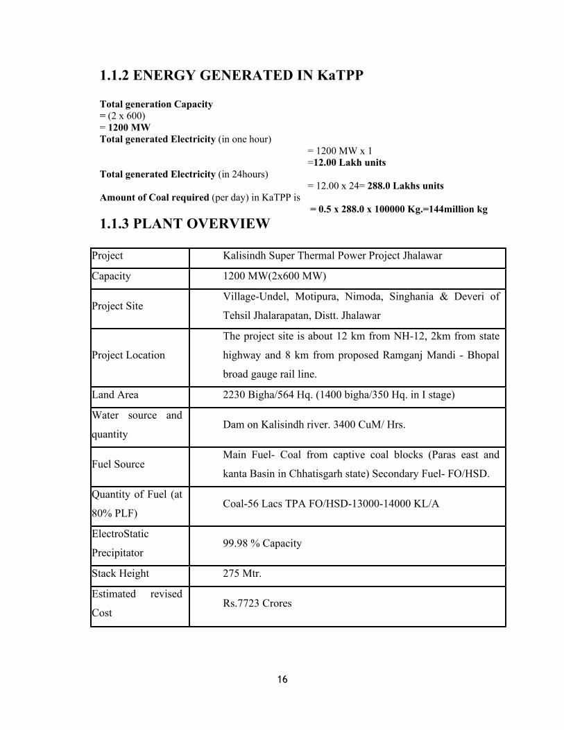
1.1.2 ENERGY GENERATED IN KaTPP
Total generation Capacity= (2 x 600)= 1200 MWTotal generated Electricity (in one hour)
= 1200 MW x 1=12.00 Lakh units
Total generated Electricity (in 24hours)= 12.00 x 24= 288.0 Lakhs units
Amount of Coal required (per day) in KaTPP is= 0.5 x 288.0 x 100000 Kg.=144million kg
1.1.3 PLANT OVERVIEW
Project Kalisindh Super Thermal Power Project Jhalawar
Capacity 1200 MW(2x600 MW)
Project SiteVillage-Undel, Motipura, Nimoda, Singhania & Deveri of
Tehsil Jhalarapatan, Distt. Jhalawar
Project Location
The project site is about 12 km from NH-12, 2km from state
highway and 8 km from proposed Ramganj Mandi - Bhopal
broad gauge rail line.
Land Area 2230 Bigha/564 Hq. (1400 bigha/350 Hq. in I stage)
Water source and
quantityDam on Kalisindh river. 3400 CuM/ Hrs.
Fuel SourceMain Fuel- Coal from captive coal blocks (Paras east and
kanta Basin in Chhatisgarh state) Secondary Fuel- FO/HSD.
Quantity of Fuel (at
80% PLF)Coal-56 Lacs TPA FO/HSD-13000-14000 KL/A
ElectroStatic
Precipitator99.98 % Capacity
Stack Height 275 Mtr.
Estimated revised
CostRs.7723 Crores

17
1.1.4 IMPORTANTMILESTONE FOR UNIT-1/2 & COMMON SYSTEM
SI
NO.Activity
Scheduled
Date U#1
Actual
Date
Scheduled
Date U#2
Actual
Date
01 Start of Boiler Foundation 28.04.2009 24.01.200911.07.2009 23.03.2009
02 Start of Boiler Erection 07.12.2009 23.10.200905.03.2010 26.03.2010
03 Boiler Drum Lifting 06.05.2010 19.05.201003.07.2010 14.08.2010
04 Readiness of startup power 12.02.2011 28.04.2011
05Completion of commissioning of
DM Plant25.12.2010 25.12.2010
06 Boiler Hydro Test 05.01.2011 08.04.201130.03.2011
07Readiness of Chimney (1st / 2nd
Flue only)02.06.2011 30.04.201127.04.2011
08 Readiness of UCB 24.09.2010 09.12.2010
09 Boiler Lightup 07.06.2011 05.09.2011
10 Start of Condenser Erection 23.06.2010 27.11.201015.11.2010
11 Start of TG Erection 30.08.2010 20.12.201008.11.2010
12Turbine Generator & Auxiliaries
Box Up24.06.2011 13.09.2011
13 Readiness of Cooling Tower 02.08.2011 02.11.2011
14 Turbine on Barring Gear 16.08.2011 02.11.2011
15 Completion of Coal handling 30.08.2011 30.08.2011
16 Completion of Ash handling 13.06.2011 19.08.2011
17 Readiness of 400 KV Switch Yard 11.12.2010 07.02.2011
18Rolling of Turbine &
Synchronisation05.09.2011 07.12.2011
19 Completion of Trial Operation 02.01.2012 02.04.2012
20 Provisional Handing Over 2013 2013

18
1.2 PRINCIPLE OF OPERATION
For each process in a vapour power cycle, it is possible to assume a hypothetical or idealprocess which represents the basis intended operation and do not produce any extraneouseffect like heat loss.1. For steam boiler, this would be a reversible constant pressure heating process of waterto form steam.2. For turbine, the ideal process would be a reversible adiabatic expansion of steam.3. For condenser, it would be a reversible a constant pressure heat rejection as the steamcondenser till it becomes saturated liquid.4. For pump, the ideal process would be the reversible adiabatic compression of liquidending at the initial pressure. When all the above four cycles are combined, the cycleachieved is called RANKINE CYCLE. Hence the working of a thermal power plant isbased upon Rankine cycle with some modification.

19
FIG-3 THERMAL PLANT PROCESS DIAGRAM
A PULVERIZED COAL FUELED POWER PLANT
A typical pulverized coal fueled power plant is based on Rankine Thermodynamic cycle.
“A Rankine cycle is a vapour cycle Furnace that relies on the isentropic expansion of
high pressure gas to produce work”. Let us see a superheat Rankine cycle:

20
FIG-4 RANKING CYCLE
Where, Wt – mechanical power produced by turbine
This facility first produces steam in a boiler (steam generator). This steam is used to
rotate turbine which is connected to a shaft of generator. Hence electricity is produced
here. The used steam is then condensed in a condenser, and the condensed liquid is used
again in the steam generator. This is a simple phenomenon, understood by everybody.
For all this we need a fuel. As the name suggest here coal is used as fuel. Coal is one of
the cheapest and most preferred fossil fuel used as a key to most of the power plants.
Usually delivered by train from Mines to the Coal Handing Plant (CHP). The CHP
unloads this it become more economical to unload the coal. Then the coal stacked,
reclaimed, crushed, and conveyed it to the storage silos near the steam generator. Then it
is fed through the Feeder to the Pulverizer. Feeder is mainly used to weight the amount of
coal going to the Pulverizer per hour. From the Feeder the coal is fed to the Pulverizer
which powders it and then it is carried to the steam generator using pressurized air.
Within the steam generator the coal is atomized and burned and the heat energy produced
is used for producing steam. Here two types of steam namely superheated & reheated
steam are produced in a cycle. The steam turbine generator converts the thermal energy
of superheated and reheated steam to electrical energy. The first energy conversion is
carried in Boiler or steam generator; the second is carried out in Turbine and the last one
carried out in the Generator.

21
FIG-5 ENERGY CYCLE
Initially the superheated steam is fed to High Pressure (HP) turbine. It has a temperature
of 540° C (approx.) and a pressure of about 140 Kg/cm2. Then the exhausted steam from
it is taken to the reheater so that it can be reheated and fed back to Intermediate Pressure
(IP) turbine. Here the temperature is maintained the same as that of superheated steam
but pressure is reduced to 35 Kg/cm2. Then the exhausted steam is directly fed to Low
Pressure (LP) turbine having the reduced temperature and pressure of about 1 Kg/cm2.
Then the exhausted steam from the LP section is condensed in the condenser. The
condensed liquid is moved from condenser by Condensate Pumps through Low Pressure
Regenerative Feedwater heaters to a Deaerator. Boiler Feed Pumps (BFPs) moves the
deaerated liquid through HP heaters to the steam generators. Extraction steam is supplied
to the LP & HP regenerative heaters to improve cycle efficiency. Then comes to the
system of fans which keeps the system working by providing the valuable air where
required. There are three pairs of fans, namely, Forced Draft (FD) fan, Induced Draft (ID)
fan, Primary Air (PA) fan. FD fans supplies combustion air to the steam generator and
PA fans transports the coal into the steam generator. ID fans remove the flue gases from
the steam generator and exhaust it through chimney. Cooling water for the condenser is
supplied by the circulating water system, which takes the heat removed from the
condenser and rejects it to the cooling towers or other heat sink. This all working is
controlled from a single place called control room. It enables the operator to direct the
plant operation for reliable and efficient production of electrical energy. This is achieved
by the control system installed by the C & I group. These are DAS (Data Acquisition
System), ACS (Analog Control System), FSSS (Furnace Safeguard Supervisory System),
and other relays governing numerous activities. Last but not the least is the switching and
transmission methods used here. The generated power cannot be transmitted as such. It is
stepped up to 132 KVA or 400 KVA then passed through a series of three switches an

22
isolator, a circuit breaker and an isolator. Three phase system is used for the power
transmission. Each generator has its own switchyard and transmission arrangement.
1.3 THERMAL PLANT OPERATION PROCEDURE
The basic understanding of the modern thermal power station in terms of major systems
involved can be done under three basic heads viz. generating steam from coal, conversion
of thermal energy to mechanical power and generation & load dispatch of electric
power.
1. COAL TO STEAM:
The coal is burnt at the rate up to 200 tonnes per hour.
From coal stores, the fuel is carried on conveyor belts to bunkers through coal tipper.
It then falls in to coal pulverizing mill, where it is grounded into powder as fine as
flour.
Air is drawn in to the boiler house by drought fan and passed through Preheaters.
Some air is passed directly to bunker and rest, through primary air fan, to pulverizing
mill where it is mixed with powdered coal.
The mixture is then carried to bunker of furnace where it mixes with rest of the air and
burns to great heat.
This heats circulating water and produces steam, which passes to steam drum at very
high pressure.
The steam is then heated further in the Superheater and fed to high pressure cylinder
of steam turbine.
The steam is then passed to other cylinders of turbine through reheater.
The spent steam is sent to condenser, where it turns back to water called condensate.
Condensate is sent to lower part of steam drum through feed heater and economizer.
The flue gases leaving boiler are used for heating purpose in feed heater, economizer,
and air Preheater.
23
The flue gases are then passed to electro-static precipitator and then, through draught
fan, to chimney.
2.STEAM TO MECHANICAL POWER:
Steam first enters the high pressure cylinder of turbine where it passes over a ring of
stationary/fixed blades which acts as nozzle and directs steam onto a ring of moving
blades.
Steam passes to the other cylinders through reheater and the process is repeated again
and again.
This rotates the turbine shaft up to 3000 rpm.
At each stage, steam expands, pressure decreases and velocity increases.
3.MECHANICAL TO ELECTRICAL POWER:
The shaft is connected to an alternator’s armature.
Thus the armature is rotated and electric current is produced in the stator’s windings.
The generated electricity is of order 25,000 volts.
4.SWITCHING AND TRANSMISSION:
Electricity generated can not be transmitted as such.
It is fed to one side of generator’s transformer and stepped up to 132000, 220000, or
400000 volts.
It is then passed to a series of three switches an isolator, a circuit-breaker, and another
isolator.
From circuit-breaker, current is taken to bus bars and then to another circuit-breaker
with it’s associated isolator before being fed to the main Grid.
Each generator has its own switching and transmission arrangement.
Three-phase system is used for power transmission.
5. CONTROL AND INSTRUMENTATION
Control and Instrumentation (C & I) systems are provided to enable the power station to
be operated in a safe and efficient manner while responding to the demands of the

24
national grid system. These demands have to be met without violating the safety or
operational constraints of the plants. For example, metallurgical limitations are important
as they set limits on the maximum permissible boiler metal temperature and the chemical
constituents of the Feed water. The control and Instrumentation system provides the
means of the manual and automatic control of plant operating conditions to:
Maintain an adequate margin from the safety and operational constraints.
Monitor these margins and the plant conditions, and provide immediate indications
and permanent records.
Draw the attention of the operator by an alarm system to any unacceptable reduction
in the margins.
Shut down the plant if the operating constraints are violated.
TYPES OF INSTRUMENTSThe different types of instruments normally used are given below:
INDICATORS – These are of two categories, namely local and remote. Local indicators
are self contained and self operative and are mounted on the site. The Remote indicators
are used for telemeter purposes and mounted in the centralized control room or control
panel. The indicators are sometimes provided with signaling contacts where ever required.
The
Remote indicators depend on electricity, electronics, pneumatic or hydraulic system for
their operation and accordingly they are named. The indicator can be classified as
analogue or digital on the basis of final display of the reading.
·RECORDERS – These are necessary wherever the operating history is required for
analyzing the trends and for any future case studies or efficiency purposes. Recorders can
be of single point measuring a single parameter or multipoint measuring a number of
parameters by single instruments. Multipoint recorders are again categorized as
multipoint continuous or multipoint dot recorders. The multipoint dot recorders select the
point one after the other in a sequence where as the continuous recorders measure
simultaneously all the poinS.
CHAPTER-02 COAL HANDLING SYSTEM

25
2.1 COAL HANDLING PLANT
INTRODUCTION:-Every thermal power plant is based on steam produced on the expanse of
heat energy produced on combustion of fuel. Fuels usednare coal and fuel oil. Coal is
more important as oil is occasionally used. Coal is categorised as follows depending upon
fixed carbon, volatile matter and moisture content:
Anthracite having 86% fixed carbon
Bituminous having 46 to 86% fixed carbon
Lignite having 30% fixed carbon and
Peat having 5 to 10% fixed carbon
Coal from mines is transported to CHP in railway wagons. It is unloaded in
track hoppers. Each project requires transportation of large quantity of coal mines to the
power station site. Each project is established near coal mine which meets the coal
requirements for the span of its entire operational life. For the purpose each plant has
Merry Go-Round (MGR) rail transportation system. The loading operation of the coal
rake takes place while it is moving under the silo at a present speed of 0.8 Km/hr. the
loading time for each wagon is one minute. For unloading of coal from the wagons an
underground track hopper is provided at the power station end.
The term coal handling plant means to store and to handle the coal which is
transported by the train and convey to the bunkers with the help of belt conveyers.
Through the bunkers coal is transferred to the coal mill and drifted to the furnace. The
coal handling plant includes wagon tippler, conveyer belt, crusher house, stacker &
reclaimer, bunkers & coal mill.
CHP then normally follows three coal paths:
1. PATH A – FROM TRACK HOPPERS TO BUNKERS.
2. PATH B – FROM TRACK HOPPERS TO STOCKYARD.
3. PATH C – FROM STOCKYARD TO BUNKERS.
PATH-A

26
PATH-B
PATH-C
FIG-06 COAL CYCLE PATH

27
FIG-07 WAGON TIPLAR, FIG-08 CRUSHUR HOUSE , PROCESS VIEW
Coal Supply in KaTPP:-Ministry of coal, Govt. of India has alloted ‘Paras east and
Kanta basin ‘ coal blocks to RVUN in Chhatisgarh state. The RVUN has formed new
company under joined venture with M/s. Adani Enterprises for mining of coal blocks
and new company started the work. Annual coal requirement for the project is 56 Lacs
MILLSThese are basically coal pulverizing mills. Thermal power stations use pulverized coal
firing system. In this the coal is reduced to fineness such that 70 to 80% passes through a

28
200 mesh sieve. This fine powdered coal is called pulverized coal and is carried forward
to the burner by air through pipes.
Advantage of pulverized coal firing system:–
1. Efficient utilization of low grade and cheap coal.
2. Flexibility in firing.
3. Ability to meet fluctuating load.
4. Better reaction to automatic control.
5. High efficiency of boiler.
6. Easy complete combustion.
The only disadvantage being its high initial cost.
2. 1 STAGES OF COAL HANDLING PLANT:- WAGON TIPPLER:-
The term Wagon Tippler contains two words WAGON & TIPPLER .Wagon
means the compartment of train which is just like a container which is used to carry the
coal from mines to generating stations & the word Tippler means a machine, which is
used to unload the wagon into the hopper. Hopper is just like a vessel which is made of
concrete & it is covered with a thick iron net on its top. Here big size coal pieces are
hammered by the labors to dispose it into the hopper.
Coal is fed into mill through Gravimetric feeder. When the A.C. supply is
switched on the bowl rotate and due to centrifugal force, the coal moves in the outward
direction. As the coal come between grinder and bowl, it gets pulverized. The unwanted
material is removed through scrapers. The pulverized coal is then carried to burners by
primary air through outlet openings. The heavier particles, as they rise, collide with
classifiers and fall back in mill for further grind. Sealing air is provided through seal air
fan to avoid deposition of coal dust in bearings and spring mechanism.
CONVEY OF COAL TO CRUSHER HOUSE:-
After unloaded the coal wagon into the concrete hopper, the supply of coal
is control by Apron Feeder and Scrapper. Apron feeder is made of iron .After passing
through the scrapper conveyor the coal is fed into the Roll Crusher where the crushing
29
of coal takes place. In the roll crusher there are two shafts on which metal hammer are
mounted, these two rollers rotates in opposite direction to each other. When the coal
comes in between these two rollers it gets crushed into small pieces and then convey to
the separator through belt conveyor. In Pent house there is a belt weightier which is used
to weight the belt which carry the coal and feed into the separator with the help of Flap
Gate .
PRIMARY CRUSHER HOUSE:-
Coal crusher house is a part of coal handling plant where the coal is
crushed with the help of a crusher machines .In crusher machine there is pair of two
shafts on which hammer are fixed. Both shafts rotates in opposite direction due to which
when coal comes between the two shafts crushed into the small pieces and conveyed to
the bunkers or open storage (stacker) according to the requirement through the belt
conveyor.
STACKER & RECLAIMER:-
Stacker is a place where the open storage of a coal takes place. Reclaimer
means the unloading of coal from the stacker.
COAL MILL:-
In coal mill, coal is pulverized or crushed properly into the powdered
form. Hot air is mixed with powdered coal to remove the moisture from the coal, which
increases the efficiency of plant. Pulverization is done to increase the surface area of
coal. From coal mill coal is drift to the furnace with the help of air. There are four main
equipment of coal mill, which are as follows:-
Bunkers:-These are basically used to store crushed coil which comes from crusher
house.
Feeders:-These are used to control the supply of crushed coal to the mill depending
upon load condition.
Feeder pipe:- Feeder pipe are used to convey the crushed coal to the Tube mill or Bowl
mill.
Tube mill:-Tube mill is used to pulverize the crushed coal. In the tube

30
CHAPTER-03,RAW-WATER CYCLE & COOLING SYSTEM
3.1 WATER TREATMENT PLANT
The principal problem in high pressure boiler is to control corrosion and
steam quality. Internal corrosion cost power station crores of rupees.
The water available can not be used in boilers as such. The objective of water
treatment plant is to produce the boiler feed water so that there shall be
· No scale formation
· No corrosion
· No priming or forming problems
The treated water is called ‘Dematerialized Water’. The treatment process can be divided
in two sections:
1. Pre-treatment section
2. Demineralisation section
PRE-TREATMENT SECTION
Pre-treatment plant removes suspended solids like clay, salt, plants,
micro-organisms etc form raw water to give clarified water. Suspended solids can be
separable or non-separable. Separable solids are heavier & large and can easily be
removed by an aerator. Non-separable solids have finer size and take long to settle down.
Hence they are required to be flocculated. In this, water is first dozed with lime and alum.
This forces finer particles to coagulate increasing their weight and size. Non-separable
solids can now be separated in clariflocculator. The clarified water is then stored in
clarified water storage tanks.
DEMINERALISATION SECTION
The clarified water now goes to FCA (activated carbon filter) where it
de-chlorinated. Water then passes through cation exchanger where weak and strong
acidic cations are removed on adding resin.
RH + Na RNa + H2SO4
Ca Ca HNO3
Mg Mg H2CO3

31
(in water) (drain) (left in water)
The water is then sent to degasser where CO2 is removed. From degasser, water comes to
anion exchanger where anions are removed.
ROH + H2SO4 RSO4 + H2O
(Resin) HCl Cl (demineralised
HNO3 NO3 water)
(From cation exchanger) (Drain)
Water thus achieved is the required demineralised water which is then stored in
demineralised water storage tanks.
REGENERATIONRecharging the exhausted form of resin i.e. regeneration employing 5% of acid/alkali as
below:
Cation resin:
RNa + HCl RH + NaCl
K (fresh KCl
Ca resin) CaCl2
Mg MgCl2
(Exhausted resin) (removed by
rinsing)
Anion resin:
RSO4 + NaOH ROH + Na2SO4
Cl (fresh NaCl
NO3 resin) NaNO3
(exhausted resin) (removed by
rinsing)
The fresh resin thus produced is reused in demineralisation process.

32
WATER TREATMENT STAGE:-River (raw water) → Clarification → Filtration → Demineralization
CLARIFICATION AND FILTERATION OFWATER:-River water contains different impurities i.e.
Suspended impurities
Biological impurities
Soluble impurities
Colloidal impurities
WORKING:-
The raw water enters through valve and than chemicals is added.
Chlorine and alum are added. Chlorine is added to remove bacteria etc. Alums are
added to make the impurities heavier, once the impurities become heavier than a no. of
flocs are formed. By mixing the alums, heavy impurities are settle down due to gravity
and later removed. The time required for the formation of floc is called retention time
which is generally 3 hours but this can’t be achieved as it require large tank. In order to
cope up the limitation CLARRIFOCCULATION TANK is used.
This flocculation tank is consist of
1. Clarification zone
2. flocculation zon
After the addition of chemical the basic requirement arises is of mixing. Thus flash
mixers are used. Normally the chemicals mix naturally but when the raw water contains
much impurity than agitators are used to mix them.
Clarrifocculation tank has a central pillar which has four windows at 90
degree. The outer circle is half of windows so that level of water is arise then it flows
down through these windows into overflow channel. After mixing from flash mixer, the
water passes on to central pillar and follows the path as shown in fig. i.e. it moves to
max. floc area and comes out from window at 3.5 m height. The downward flow is
through perforated wall which sinks the raw water. Due to the long path a retention time
of 4 hour is easily available.
33
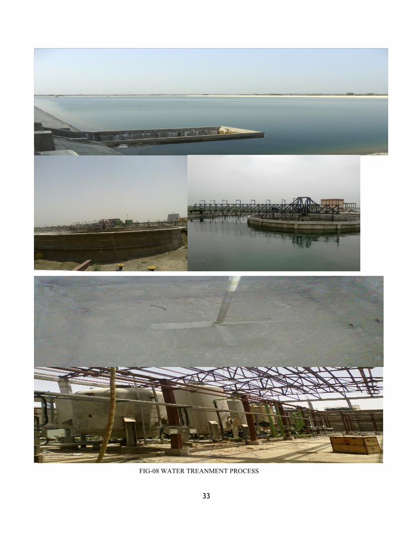
FIG-08 WATER TREANMENT PROCESS

34
FIG-9 CLORIFICATION SYSTEM, FIG-11WATER FLOW CYCLE
35
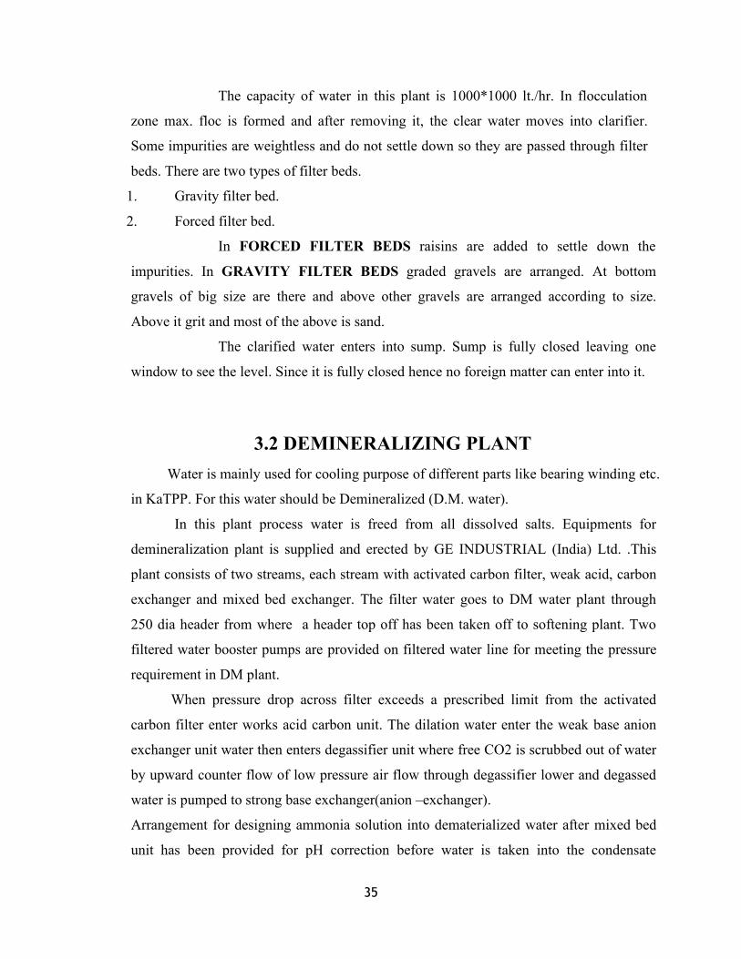
The capacity of water in this plant is 1000*1000 lt./hr. In flocculation
zone max. floc is formed and after removing it, the clear water moves into clarifier.
Some impurities are weightless and do not settle down so they are passed through filter
beds. There are two types of filter beds.
1. Gravity filter bed.
2. Forced filter bed.
In FORCED FILTER BEDS raisins are added to settle down the
impurities. In GRAVITY FILTER BEDS graded gravels are arranged. At bottom
gravels of big size are there and above other gravels are arranged according to size.
Above it grit and most of the above is sand.
The clarified water enters into sump. Sump is fully closed leaving one
window to see the level. Since it is fully closed hence no foreign matter can enter into it.
3.2 DEMINERALIZING PLANTWater is mainly used for cooling purpose of different parts like bearing winding etc.
in KaTPP. For this water should be Demineralized (D.M. water).
In this plant process water is freed from all dissolved salts. Equipments for
demineralization plant is supplied and erected by GE INDUSTRIAL (India) Ltd. .This
plant consists of two streams, each stream with activated carbon filter, weak acid, carbon
exchanger and mixed bed exchanger. The filter water goes to DM water plant through
250 dia header from where a header top off has been taken off to softening plant. Two
filtered water booster pumps are provided on filtered water line for meeting the pressure
requirement in DM plant.
When pressure drop across filter exceeds a prescribed limit from the activated
carbon filter enter works acid carbon unit. The dilation water enter the weak base anion
exchanger unit water then enters degassifier unit where free CO2 is scrubbed out of water
by upward counter flow of low pressure air flow through degassifier lower and degassed
water is pumped to strong base exchanger(anion –exchanger).
Arrangement for designing ammonia solution into dematerialized water after mixed bed
unit has been provided for pH correction before water is taken into the condensate
36
transfer pump the DM water to unit condenser as make up. The softening plant is a plant
designed to produce 100 cubic m/hr. of softened water per stream. It is using for bearing
cooling.
PH VALUE OFWATER:-
This is recommended to feed the water in the boiler at 25 degree
centigrade and pH value is 8.2 to 9.2 up to 28 days and the pressure is 59 Kg \cm2.
3.3 COOLING TOWER
It is used to reject heat into the atmosphere. There are two types of the cooling tower.
(1) Natural draft
(2) Forced draft
Natural draft tower used vary large concrete chimney to introduce air
through the media. They are generally used for water flow rate about 45000 m3 /hour. It
is used in utility power station.Here hight of cooling tower is 202M.
Forced draft tower utilize large fans to force or suck air through
circulating water. The water falls downward over fills surface which helps in increase the
contact time between the water and air. This held maximize heat transfer between two
media. Cooling rates depend upon fan diameter and speed. This type of tower much
wider used.
Here 2 NDCT used each of two units and hight of cooling tower is 202
meter.water tubes are used inside of cooling tower for cooling purpose.
This structure is constructed in r.c.c. shell poud floor and its derified water
channel c.w. For bay. The entire structure is supported combined circular rafting
constructed in different segments with slanted colomn fotting to support 17 m hight
circular sectional reckar colmns. This r.c.c. shell of 150 m dia. And 205 m height . It is
made of m 50 grade r.c.c. Which was also done at sight. There will be 200 colomns poud
floors that will generate cascading effect for cooling.
The cooling tower shell be capable of cooling the rated quality of water

37
through the specified thermal range at the design wet bulb temperature.
Minimum grade of concrete to be used for all the structure elements as :
Structure minimum grade
Foundations M 30
Basin M 35
Diagonal colomn M 40
Shell M 35
Precast work M 35
Foundations:
The design and construction of cooling tower foundations shell be in accordance with the
requirments continuous foundations shell be provided for cooling tower more then 75 m
height. The foundation is design for loadis indicated in as follows:-
A.) Thermally induced local loading
B.) Cold water basin floor loading
C.)Surface charge load of 15 KN per 50m
The basin floor at each compartment should be sloped towards a collecting sump for
effectively drainage the water to permitt desilting. To minimize the obstruction in flow
of water only the colomns supporting the fill structure shell be projected above the basin
floors.
BEARING COOLINGWATERWater from river comes in plant heat exchanger, where its temperature
cools down and that goes in AHP to make slurry. There are 480 plates’ exchangers. BCW
requirements of boiler and turbine auxiliaries of both the units is meet from BCW soft
water overhead tank with the capacity of 2000 cubic meter

38
FIG-10 COOLING TOWER

39
DEAERATOR:-DEAREATION OF FEEDWATER:-
In deareation dissolve gases such as oxygen & CO2 are expelled by
preheating the feed water before it enters the boiler. All natural water contains dissolve
gases in solution (i.e. oxygen + CO2) are released when water heated.
CONDENSER:-In condenser steam changes into water. The basic requirement is to
remove latent heat from the steam which is removed by another water (clarified water)
when it accepts the latent heat and becomes hot, than it is passed to cooling tower. In
cooling tower the water is cooled and then mix with river water.
PUMPS:-The entire green colored instrument is pumps which are 18 in no. to further pass the water.
1. FILTERWATER TRANSFER PUMP:-It is soft section consisting two types:-
BEARING COOLINGWATER PUMP:-
All the bearing temperature is controlled through oil bath and filter
water is used. Oil is used to cool the supplied water. Here doesn’t used raw water
because at the time of puncture it enters in the machinery part and small impurity may
stop the operation.
CONDENSATEWATER PUMP:-
This pump is coupled with blue colored motor. In order to couple it with
motor a little opening is left through which water leaks out when pumped
2. FILTERWATER TRANSFER PUMP:-This pump transfers water to D.M. plant. These pumps are in D.M.
section.
3.POTABLE WATER PUMP:-These pump pumps clear water for potable
purpose for whole plant.
40
3.4 H2 GENERATING PLANT
Hydrogen gas is used for cooling purpose for rotor of the generator. For
cooling purpose we have to use 99.9% pure hydrogen. To avoid fire so we have to apply
Hydrogen cooling. It is very difficult to generate and store the Hydrogen gas because it
is very explosive. Hydrogen as a coolant has the following advantages over air:
1. More efficiency and less noise.
2. Better Cooling.
3. More life and less maintenance.
4. Less chance of fire hazard.
5. Better rating.
GENERATING PLANT:-Hydrogen gas is produced by electrolytic dialysis by mixing KOH in D.M. water.
This reaction is done in electrolyser where Anode and Cathode are applied. Anode plate
is used for collecting H2 and Cathode plate is used for collecting O2. For electrolytic
dialysis 3000 Ampere current is passed into electrolyser. O2 is released to atmosphere
and H2 is sent to next machinery for further treatment.
COLLECTING PROCESS:-H2 Gas from electrolyser → Refrigerator for cooling → Separator to separate the
moisture → Compressor → Catalytic purifier → Dryer (Al2O3) → H2 cylinder. In
compressor H2 is treating in three steps where pressure is raised up to 130 Kg/cm2. In
dryer Alumina is used to absorb moisture.
CAPACITY:-In KaTPP the full day capacity of H2 generating is Not calculated because plant
is in on constraction.its appxi 40 cylinders per day. But in plant per day utilization are
of 15 cylinders. Per cylinder capacity is 200-250 kg and stored H2 is 99.8% pure.

41
CHAPTER-04 STG SYSTEM
4.1 BOILER
Boiler can simply defined as the device where any liquid is boiled or Boiler
may be defined as a device that is used to transfer heat energy being produced by burning
of fuel to liquid, generally water, contended in it to cause its vaporization. Boiler, in
simple terms, can be called “Steam Generator”. The following are factors essential for the
efficient combustion usually referred as “The three T’s”.
A) TIME – It will take a definite time to heat the fuel to its ignition temperature and
having ignited, it will also take time to burn.
B) TEMPERATURE – A fuel will not burn until it reaches its ignition temperature.
C) TURBULENCE – Turbulence is introduced to achieve a rapid relative motion
between the air and fuel particles.
CLASSIFICATION:
Boilers may be classified under different heads on different basis:-
1. Depending upon “Use”
1.1. Stationary (land) boilers
1.2. Mobile boilers
1.2.1. Marine boilers
1.2.2. Locomotive boilers
2. Depending upon “Tube contents”
2.1. Fire tube boilers
2.2. Water tube boilers
3. Depending upon “Tube shape”
3.1. Straight tube boilers

42
3.2. Bent tube boilers
3.3. Sinuous tube boilers
4. Depending upon “Tube position”
4.1. Horizontal or Vertical
4.2. Inclined
5. Depending upon “Furnace position”
5.1. Externally fired
5.2. Internally fired
6. Depending upon “Heat source”
6.1. Solid, liquid or gas
6.2. Waste of chemical process
6.3. Electrical energy
6.4. Nuclear energy
7. Depending upon “Circulation”
7.1. Natural circulation
7.2. Positive or forced circulation
A boiler is an enclosed that provides a means for combustion heat to be
transfer into water until it becomes heated water or steam. Its volume increases 1600
times. The process of heating a liquid until reaches its gaseous states its called
evaporation. The boiler system comprises of
feed water system
steam system
Fuel system
1. Feed Water system:-It provides water to the boiler and regulate feed according to demand.
2. Steam system:-

43
It collects and controls the steam produced in the boiler steam are
directed through a piping system to a point of use. Steam pressure is regulated using
valves and checked with pressure gauges.
3. Fuel system:-Fuel system includes all equipments used to provide fuel to generate the
necessary heat for higher boiler efficiency feed water is preheated by economizer using
the waste heat in the flue gases.
WATER TUBE TYPE BOILER USED IN KaTPPWITH 97M HIGHT
Various motors use in boiler are different rating and parameters
32KW ,15KW,11KW,&3.3KW
Parameter in 15KW motor
BOILER MOTOR DATA
Manufacturing CQ.GEAR BOX LTD.CHAINA
Motor rating 15KW
Speed 970rpm
Rated voltage 416V
Rated current 28.4A
Impedance voltage 80.0%
Oil waight 20kg
Core+winding waight 224kg
Total waight 600kg
Temp rise 50-55deg cel.

44
FIG-11 FLOW OF WATER & STEAM ,FIG-12 KaTPP BOILER

45
BOILER AUXILIARIESEfficiency of a system is of most concerned. Thus it is very important to maintain a
system as efficient as possible. Boiler auxiliaries help in improving boiler’s efficiency.
Following are the important auxiliaries used
ECONOMIZER: Its purpose is to preheat feed water before it is introduced into boiler
drum by recovering heat from flue gases leaving the furnace.
SUPER HEATER: It increases the temperature of steam to super heated region.
REHEATER: It is used for heat addition and increase the temperature of steam coming
from high pressure turbine to 540o.
SOOT BLOWER: It blows off the ash deposited on the water wall surface. It uses steam
for blowing purpose.
AIR PREHEATER: It pre-heats the air entering the furnace by recovering heat from
flue gases in order to ease the combustion process.
DRAFT FANS: They handle the supply of air and the pressure of furnace.
OIL GUNS: They are used to spray oil to raise the temperature of furnace to ignition
temperature of fuel.
WIND BOX: It distributes the excess air uniformly through out furnace.
BOILERMOUNTINGSThese are used for the safe operation of boiler. Some examples of mountings used are
water level indicator in drum, furnace temperature probe, reheat release valve, pressure
gauges indicating steam pressure etc.

46
4.2 TURBINE
Turbine is an m/c in which a shaft is rotated steadily by the impact of
reaction of steam of working substance upon blades of a wheel. It converts the potential
energy or heat energy of the working substance into mechanical energy. When working
substance is steam it is called ‘Steam Turbine’
In the steam turbine the pressure of the steam is utilized to overcome
external resistance and the dynamic action of the steam is negligibly small.
PRINICIPLE:-Working of the steam turbine depends wholly upon the dynamic action
of steam. the steam is caused to fall with pressure in a passage of nozzle, due to this fall
in pressure, a whole amount of heat energy is converted into mechanical energy &
steam is set moving with the reactor velocity. The rapidly moving particle of steam
enter the moving part of turbine and here suffers a change in the direction of motion
which gives rise to change of momentum and therefore to a force. This constitutes a
driving force to a machine.
The passage of the m/c through the moving part of the turbine commonly
called the blade, may take place in such a manner that the pressure at the outlet sides of
the blade is equal to that of the inlet side. Such a turbine is broadly termed as outlet
turbine or Impulse type
On the other hand, the pressure of the steam at outlet from the moving
blade may be less than that at type inlet side of the blade. The drop of pressure suffered
by the steam during its flow through the moving blades causes a further generation of
kinetic energy within the blades and adds to the propelling force which is applied to the
turbine rotor, such a turbine is broadly termed as Reaction Turbine.Here in kalisindh
thermal N600-16.7/587/537,Re-Het,Three Casing Four Exhaust,Tandem Compound
Condenser Type Turbine Used.

47
TURBINE SPECIFICATION: -
Rated output with extraction flow- 600MW
Speed - 3000rpm
Main steam throttle flow at HP Inlet - 1848.5 TPH
Main steam pressure to HP turbine
inlet -
167kg/sq.-cm.
Main steam temp.to HP turbine inlet - 538 deg.cel
Re-heater steam flow at IP inlet- 1587.942 TPH
Re-heater steam temp. at IP inlet - 538 deg.cel
Steam pressure at LP inlet - 35.12 kg/sq-cm
Steam flow at LP inlet- 1353.7 TPH
Rotation direction(view from turbine)- anticlock wise
Number of stages- 42
High pressure turbine -(a)intermediate pressure-(b)low pressure turbine-(c)governing sys
1 governing,& 8 pressure5 pressure stage2x2x7 pressure stageDEH(digital electro hydrolic)
Inlet steam flow governing type- nozzle +throttle
Rated exhaust pressure – 0.09kg/sq-cm
Type of bearings turbine - 6 journal +1 thrust
Turbine allowable frequency - 47.5 to 51.5 Hz
Turning gear rotation speed - 1.5 rpm
Ist critical speed of HP &LP rotor - 1722rpm
Ist critical speed of LP-A rotor- 1839rpm
Ist critical speed of LP-B rotor - 1903rpm
Heat regenerative extraction system – 3 HP heater +1 deaerator +4 LP heater
Final feed water temp.- 274.9 deg.cel.
Maximum bearing vibration- 0.076 m
Maximum allowable exhaust temp.- 80 deg.cel.
Cooling water design flow at
condenser-
70200TPH

48
FIG-13 (1)TURBINE DIAGRAM ,FIG-14 HP & LP ROTOR

49
4.3 GENERATOR
FIG-15 GENERATOR DIAGRAM
Generator is the main part of thermal power station or any power plant.
A generator is a machine which converts mechanical energy into electrical energy.
The generator has gas cooling construction enclosing the stator winding,
core and hydrogen coolers .The cooling medium hydrogen is contained within the frame
and circulation by fans mounted on either ends of the rotor .The generator is driven by
directly coupled steam turbine at a speed of 3000 rpm.
Provision has been made for circulating the cooling water in order to
maintain a constant temperature of the coolant i.e. H2 as measured at the fan section side
which is in touch with the temperature of the winding, core and other parts as per load.
Each of the 2 units have been provided with 3-phase turbo generator rated
output 706MVA, 18.525KA, 22KV, 0.85 lagging p.f., 984 rpm and 50 cycles/sec .The
generator has closed loop of hydrogen gas system for cooling of the stator and rotor at a
pressure of 4.5kg/sq-cm(g). is filled in a gas tight outer casing of the generator. H2 gas
circulates inside the casing by two single stage rotor mounted fans on either side of the
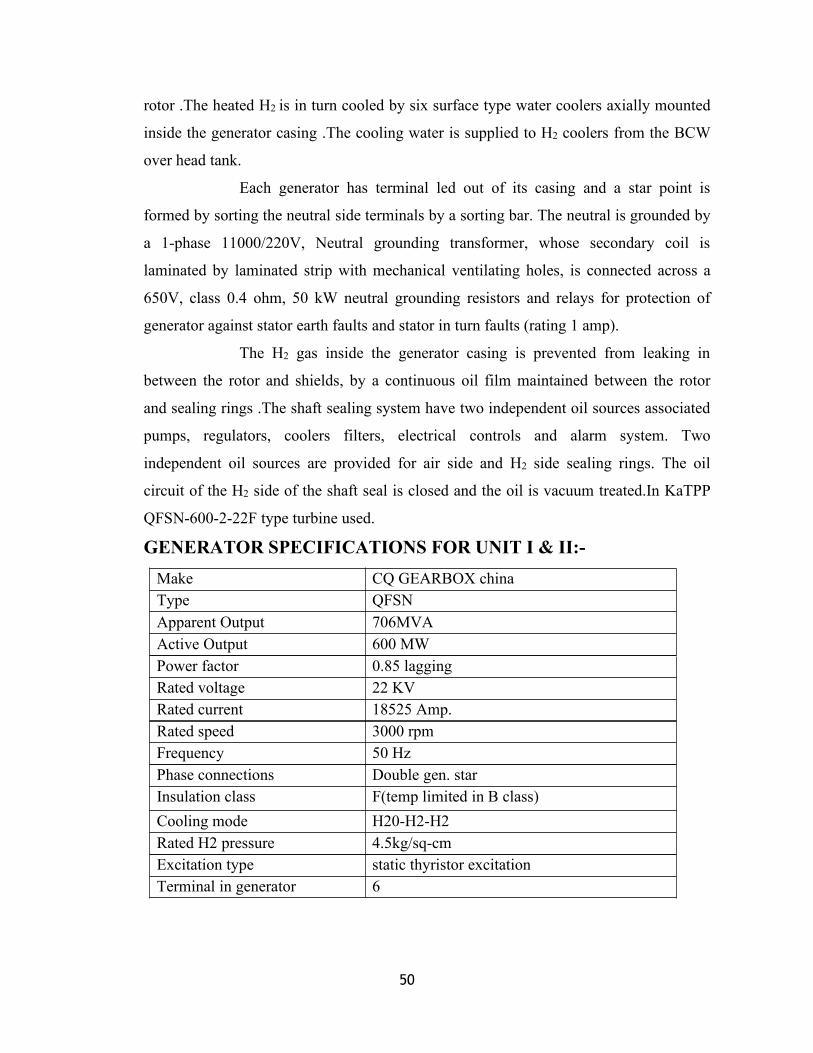
50
rotor .The heated H2 is in turn cooled by six surface type water coolers axially mounted
inside the generator casing .The cooling water is supplied to H2 coolers from the BCW
over head tank.
Each generator has terminal led out of its casing and a star point is
formed by sorting the neutral side terminals by a sorting bar. The neutral is grounded by
a 1-phase 11000/220V, Neutral grounding transformer, whose secondary coil is
laminated by laminated strip with mechanical ventilating holes, is connected across a
650V, class 0.4 ohm, 50 kW neutral grounding resistors and relays for protection of
generator against stator earth faults and stator in turn faults (rating 1 amp).
The H2 gas inside the generator casing is prevented from leaking in
between the rotor and shields, by a continuous oil film maintained between the rotor
and sealing rings .The shaft sealing system have two independent oil sources associated
pumps, regulators, coolers filters, electrical controls and alarm system. Two
independent oil sources are provided for air side and H2 side sealing rings. The oil
circuit of the H2 side of the shaft seal is closed and the oil is vacuum treated.In KaTPP
QFSN-600-2-22F type turbine used.
GENERATOR SPECIFICATIONS FOR UNIT I & II:-Make CQ GEARBOX chinaType QFSNApparent Output 706MVAActive Output 600 MWPower factor 0.85 laggingRated voltage 22 KVRated current 18525 Amp.Rated speed 3000 rpmFrequency 50 HzPhase connections Double gen. starInsulation class F(temp limited in B class)Cooling mode H20-H2-H2Rated H2 pressure 4.5kg/sq-cmExcitation type static thyristor excitationTerminal in generator 6
51
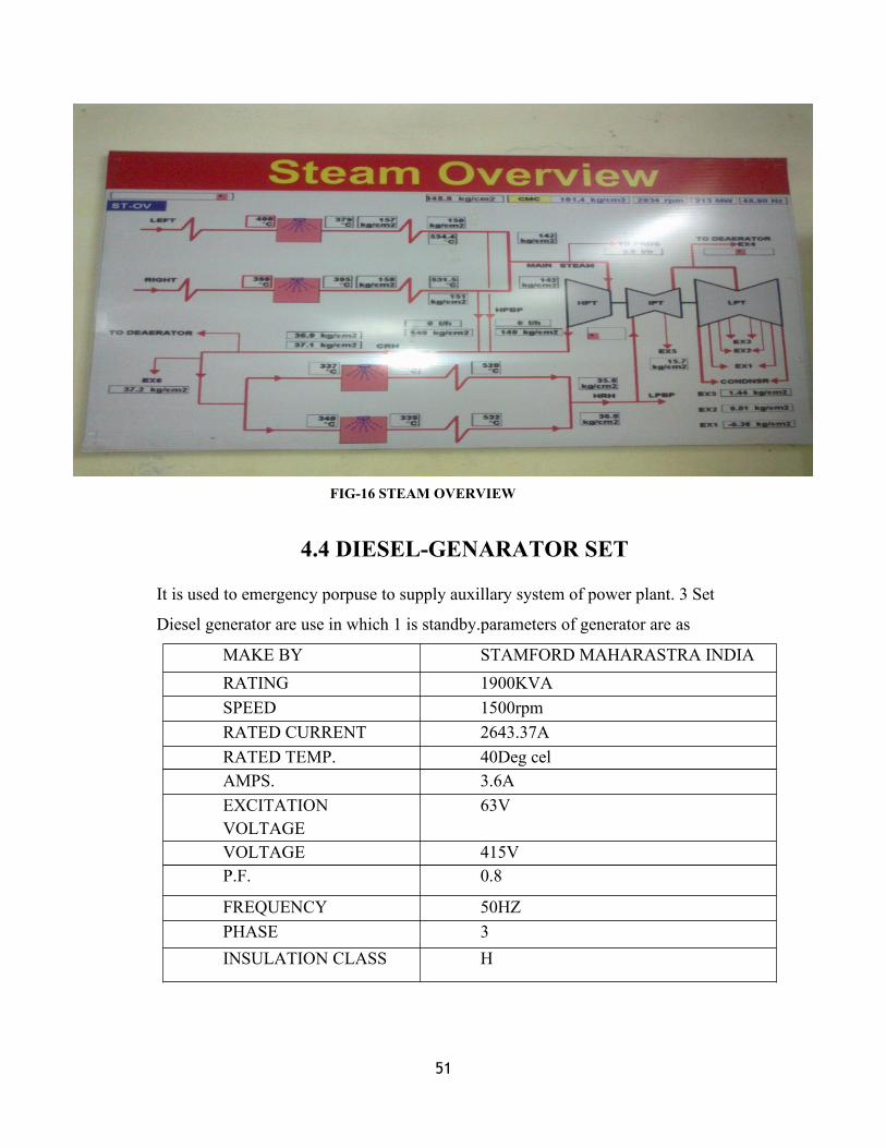
FIG-16 STEAM OVERVIEW
4.4 DIESEL-GENARATOR SET
It is used to emergency porpuse to supply auxillary system of power plant. 3 Set
Diesel generator are use in which 1 is standby.parameters of generator are as
MAKE BY STAMFORD MAHARASTRA INDIARATING 1900KVASPEED 1500rpmRATED CURRENT 2643.37ARATED TEMP. 40Deg celAMPS. 3.6AEXCITATIONVOLTAGE
63V
VOLTAGE 415VP.F. 0.8
FREQUENCY 50HZPHASE 3INSULATION CLASS H

52
CHAPTER-05 TRANSFORMER & SWITCHYARD SYSTEM
5.1 TRANSFORMER
Transformer is made up of following parts:-
1. Core
2. Winding
3. On load tap changer
4. Tank
5. Bushing
6. Auxiliary equipment
7. Insulating Oil
8. Cooling system
In KaTPP there are various transformers for various purposes. They are:-
1.Generating Transformer(GT)
2.Unit Transformer(UT)
3.Unit Auxiliary Transformer(UAT)
4.Inter Connecting Transformer(ICT)
5.Unit Service Transformer
6.Station Transformer
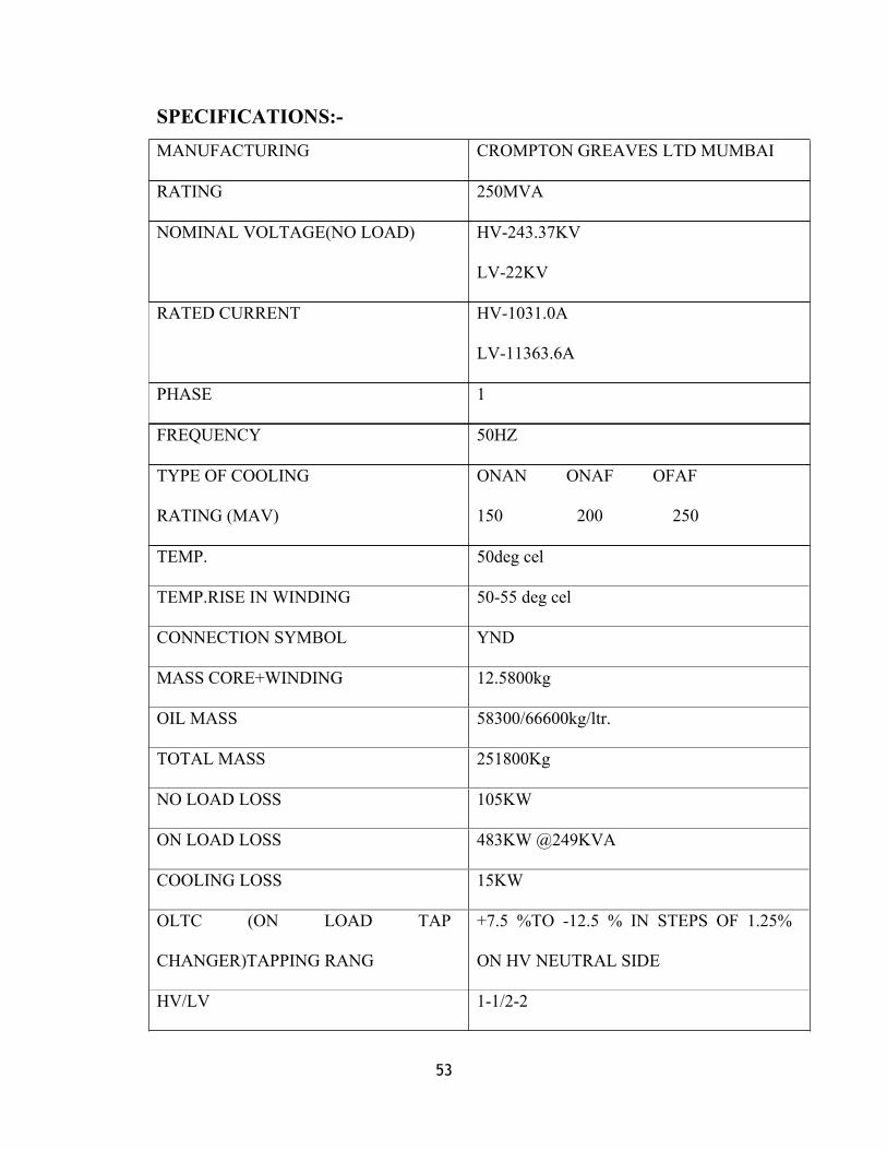
GENERATING TRANSFORMER:-At KaTPP , 3 single phase GT Installed for each phase in single unit.output of generator
has step up up to 400KV by GT.In KaTPP 150/200/250MVA,22.98/22 KV, G T are
used.
53
SPECIFICATIONS:-MANUFACTURING CROMPTON GREAVES LTD MUMBAI
RATING 250MVA
NOMINAL VOLTAGE(NO LOAD) HV-243.37KV
LV-22KV
RATED CURRENT HV-1031.0A
LV-11363.6A
PHASE 1
FREQUENCY 50HZ
TYPE OF COOLING
RATING (MAV)
ONAN ONAF OFAF
150 200 250
TEMP. 50deg cel
TEMP.RISE IN WINDING 50-55 deg cel
CONNECTION SYMBOL YND
MASS CORE+WINDING 12.5800kg
OIL MASS 58300/66600kg/ltr.
TOTAL MASS 251800Kg
NO LOAD LOSS 105KW
ON LOAD LOSS 483KW @249KVA
COOLING LOSS 15KW
OLTC (ON LOAD TAP
CHANGER)TAPPING RANG
+7.5 %TO -12.5 % IN STEPS OF 1.25%
ON HV NEUTRAL SIDE
HV/LV 1-1/2-2
54
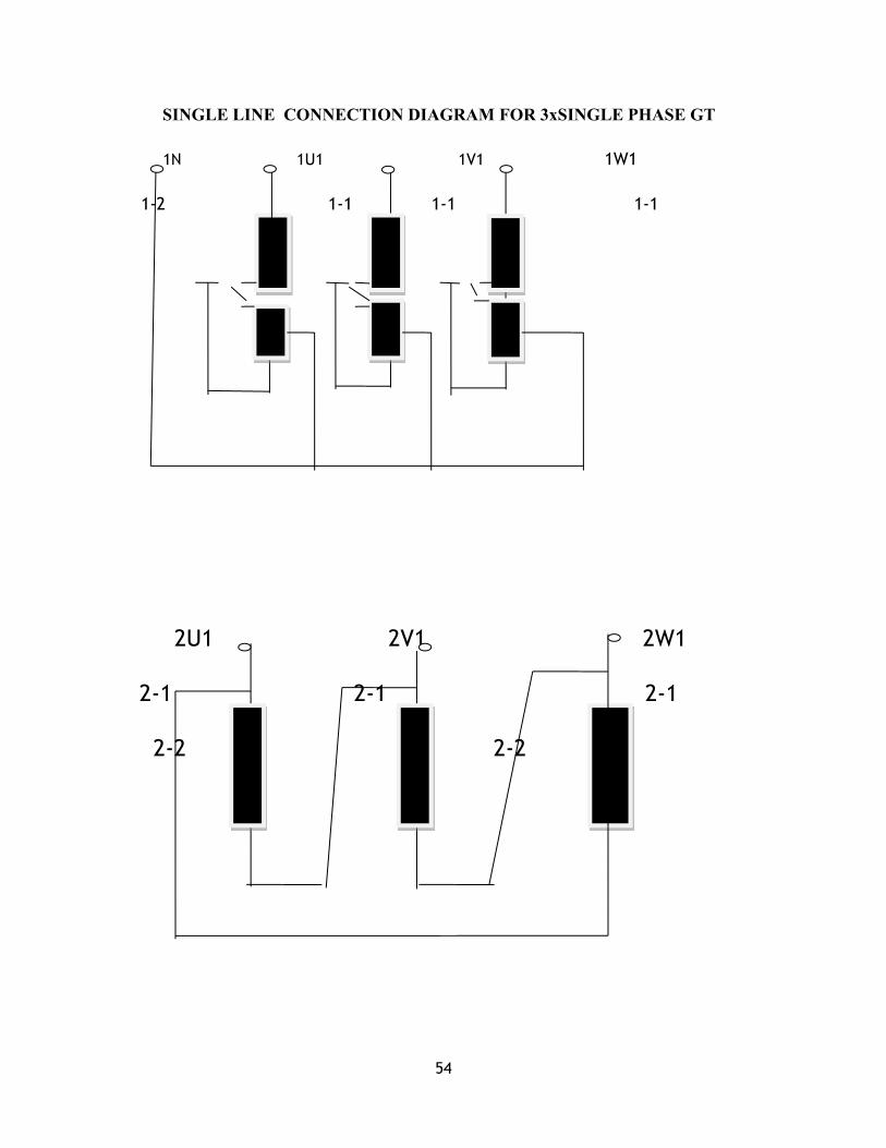
SINGLE LINE CONNECTION DIAGRAM FOR 3xSINGLE PHASE GT
1N 1U1 1V1 1W1
1-2 1-1 1-1 1-1
2U1 2V1 2W1
2-1 2-1 2-1
2-2 2-2

55
FIG-17 1 .GT 2.U.T 3. UAT

56
UNIT TRANSFORMER:-
Unit Transformer are installed to fed supply to HT switchgear.there are two
80MVA Transformer installed near GT which are fed throw main busducts coming
from generator and fed to the HT switchgear.After step down THIS SUPPLY UP TO 11
KV HT switchgear used to supply on the major auxillary of the plant like
BFP,CWP,ID,FD,PA fens etc.The unit transformer is used to HT switchgear and it
supply voltage 22/11KV to UAT and different motors in boiler.UT is rated for
48/64/80MVA,22/11.6/11.6KV , Dyn11yn11 type winding. This permit to voltage
dowan up to 11KV.it have 2 radiator.
SPECIFICATIONS:-Manufactured BHARAT BIJLEE LTD. MUMBAI
Total no. provided 2
Type of construction CORE
Rated output 48/64/80 MVA
Rated voltage at no load 22/11.6/11.6KV
Phase HV/LV1/LV2 3
Frequencycy 50 Hz
Oil Temp. Rise 50deg cel
Winding Temp. Rise 50-55 deg cel
Connection symbol Dyn11yn11
Insulation level p.f/impulse
H V 50KV(rms)/125KVp
LV1-LV2 28KV(rms)/75KVp
LVN1-LVN2 28KV(rms)/75KVp
Winding +core mass 47500kg
Mass/volume of oil 23300/27100 kg/ltr
Total mass 107000kg

57
SINGLE LINE DIAGRAMLV1
2N1S2 2 2 2
CORE1
2N1S1
1 1 1
2N2S2 2V1S2
CORE2 WTICT
2N2S2 2V1S1
NCR 2N2 2U1 2V1 2W1
LV2
2N1S11 2 2 2
CORE1
2N1S12
1 1
2N2S21 2V1S22
CORE2 WTICT
2N2S22 2V1S11
NCR 2N2 2U2 2V2 2W2
1U 1V
1W
1U1S1 1V1S1
1W1S1
CORE1 CORE 1
CORE 1
1U1S2 1V1S2
1W1S2
1U2S1 1V2S1
1W2S1
CORE2 CORE2
CORE2
1U2S2 1V2S2
1W2S2
1U2S1 1V3S1
1W3S1
CORE3 CORE3
CORE3
1U3S2 1V3S2
1W3S2
1V1S1
WTICT
1V1S2

58
UNIT AUXILLIARY TRANSFORMER:-
There is one more Transformer known as Station Transformer used only for initializing
the start-up of the station (Main Plant).It is very beneficial during emergency situations
such as tripping of Units, shut-down etc.
In KaTPP 2 UAT used for step down voltage 11/3..3KV supply
used to switchgear equipments.
INSTRUMENT TRANSFORMER:-Instrument transformer have wide range in application such as
measurement of voltage, current, power & energy power factor, frequency. It is also
used for protection circuit of the power system for operation of over current, under
voltage, earth fault and other type of relays, The instrument transformer can be
classified as
(A). CURRENT TRANSFORMER:-
Current transformer is used for monitoring the current for the purpose of
measuring and protection.The dead tank current transformer accommodate the
secondary cores inside the tank which is at ground potential. CT used current ratio
1000:1 and range is 1A-5A.
(B). POTENTIAL TRANSFORMER:-
The function of P.T. is to step down the voltage so that it can be
measured by standard measurement.Output in pt is 110V.The transformer is generally
core type and form Y-Y group and having the insulation as oil and papers.

59
CHAPTER-06,ESP & ASP SYSTEM
6.1 ELECTRO STATIC PRECIPITATORIf suspended particles are not removed from the flue glass, and it is allowed
to be released in environment, then it would cause a serious threat to the environment, so
it becomes necessary to extract suspended particles from the flue glass and for this
purpose ESP is widely used. Precipitation of ash has another advantage too. It protects
the wear and erosion of ID fan. To achieve the above objectives, Electrostatic Precipitator
(ESP) is used. As they are efficient in precipitating particle form submicron to large size
they are preferred to mechanical precipitation.
WORKING PRINCIPLE:-An electrostatic precipitator is defined as a device which utilizes
electrical forces to separate suspended particles. The electrostatic precipitator consists
of two sets of electrodes , one in form of thin wire called “discharge or emitting
electrode” and other set is called “collecting electrode” in there form of plate ESP
POWER SUPPLY COMPONENT .
CONSTRUCTION:-The main parts of ESP are as follows:-
Casing
Hoppers
Collecting system
Emitting system
Rapping mechanism for collecting system
Rapping mechanism for emitting system
60
Insulator housing
CASING:-
It is designed for horizontal gas flow to provide for heat expansion, the casing is
supported by roller bearing support.
HOPPERS:-
They are of pyramidal shape .Angle between hopper corner and Hz is never less than 55
degree.
COLLECTOR SYSTEM:-
The profiled collecting electrode is based on the concept of dimensioned electrode
stability .The upper plates have hooks and lower edge has a receiving plate.
EMITTING SYSTEM:-
The framework is thoroughly braced and forms a rigid box like structure, the emitted
electrode is made of hard stainless steel wires.
RAPPING MECHANISM FOR COLLECTING SYSTEM:-
The system employs fumbling hammer which are mounted on an Hz. Shaft in a
staggered fashion .A uniform rapping effect is provided for all collecting plates in one
row .Rapping frequency is very low to minimize the dust loss. The hammers are
operated by motor, so that they strike the plate at fixed frequency.

61
6.2 ASH HANDLING PLANT(A.H.P)
The ash produced on the combustion of coal is collected by ESP. This ash is now
required to be disposed off. This purpose of ash disposal is solved by Ash Handling Plant
(AHP). There are basically 2 types of ash handling processes undertaken by AHP:
· Dry ash system
· Ash slurry system
DRY ASH SYSTEMDry ash is required in cement factories as it can be directly added to cement. Hence the
dry ash collected in the ESP hopper is directly disposed to silos using pressure pumps.
The dry ash from these silos is transported to the required destination.
ASH SLURRY SYSTEMAsh from boiler is transported to ash dump areas by means of sluicing type hydraulic
system which consists of two types of systems:
Bottom ash system
Ash water system
BOTTOM ASH SYSTEM
In this system, the ash slag discharged from the furnace is collected in water impounded
scraper installed below bottom ash hopper. The ash collected is transported to clinkers by
chain conveyors. The clinker grinders churn ash which is then mixed with water to form
slurry.
ASHWATER SYSTEM-
In this system, the ash collected in ESP hopper is passed to flushing system. Here low
pressure water is applied through nozzle directing tangentially to the section of pipe to
create turbulence and proper mixing of ash with water to form slurry. Slurry formed in
above processes is transported to ash slurry sump. Here extra water is added to slurry if
required and then is pumped to the dump area.
FLY ASH SYSTEM
62
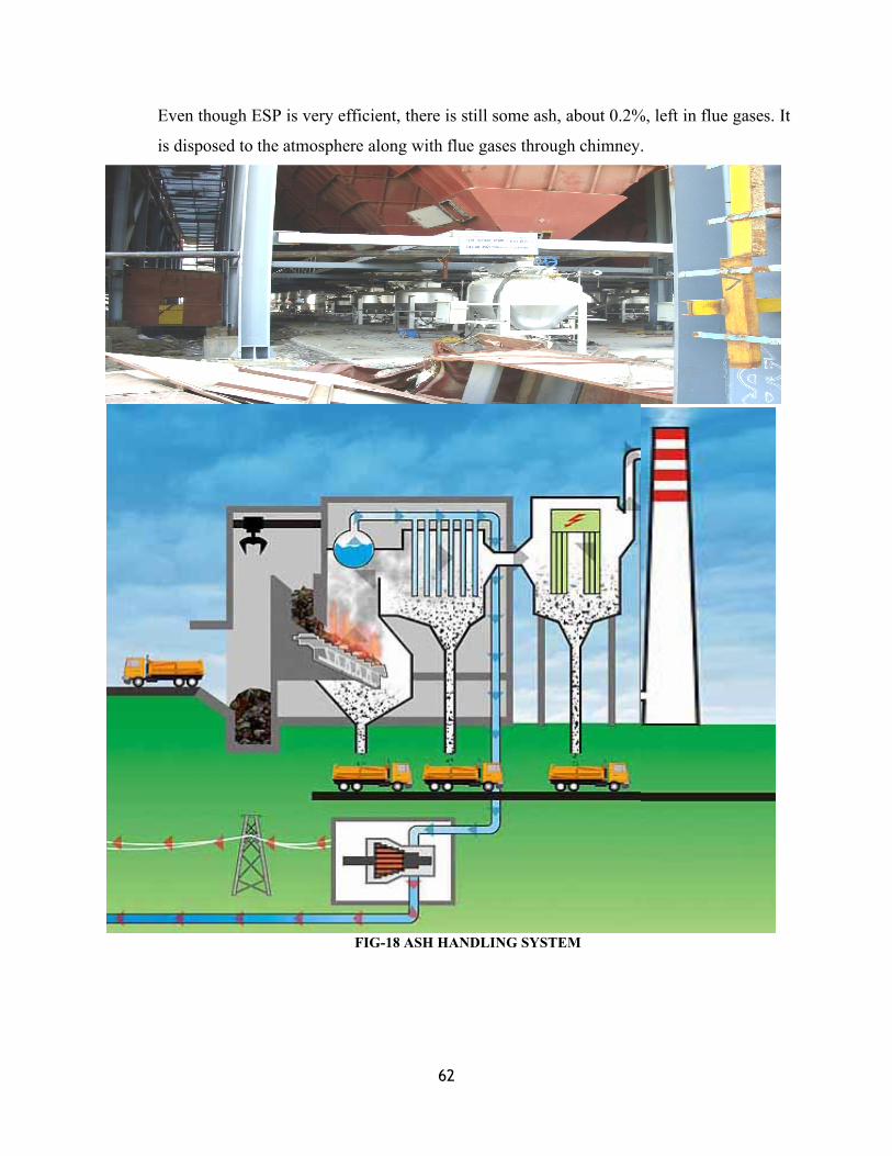
Even though ESP is very efficient, there is still some ash, about 0.2%, left in flue gases. It
is disposed to the atmosphere along with flue gases through chimney.
FIG-18 ASH HANDLING SYSTEM

63
CHAPTER-07,SWITCHYARD , C & I SYSTEM
7.1 SWITCH YARD
Switchyard is considered as the HEART of the Power Plant. Power
generated can be worthful only if it is successfully transmitted and received by its
consumers. Switchyard plays a very important role as a buffer between the generation
and transmission. It is a junction, which carries the generated power to its destination (i.e.
consumers). Switchyard is basically a yard or an open area where many different kinds of
equipments are located (isolator, circuit breaker etc…), responsible for connecting &
disconnecting the transmission line as per requirement (e.g. any fault condition). Power
transmission is done at a higher voltage. (Higher transmission voltage reduces
transmission losses).
Both units is 22KV in KaTPP. stepped-up to 400KV by the Generating transformer &
then transmitted to switchyard. Switchyards can be of 400KV, & 200KVIn SSTPS there
are two interconnected switchyards:-
(i) 400KV SWITCHYARD
(ii) 220KV SWITCHYARD
The 400KV & 220KV switch yard have conventional two buses arrangement with a bus
coupled breaker. Both the generator transformer and line feeder taking off from switch
yard can be taken to any of the two buses, similarly two station transformer can be fed
from any two buses. Each of these line feeders has been provided with by pass isolators
connected across line isolators and breaker isolators to facilitate the maintenance of line
breaker. Each 400KV & 220KV lines have provision of local break up protection. In
event of breaker which corresponding to bus bar differential protection scheme and trips
out all the breakers and connected zone bus bars differential protection scheme for bus I
& II. All the breaker of the connected zone and bus coupler, breaker will trip in event of
fault in that zone. Here in KaTPP 4 out going line are as below:-
1.400KV TO BTAWDA
2.400KV TO BTAWDA

64
3.220KV TO JHALAWAR
4.220KV TO JHALAWAR
Each of the two bus bars has one P.T. one for each phase connected to it. Potential
Transformer are make in CROMPTON LTD. Each time line feeders has two nos. Core
for each phase capacitor voltage Transformer. for metering and protection are
multicored single phase, oil filled, nitrogen sealed and are provided at rate of one per
phase.-
FIG-19 SWITCHYARD
65
400KV SWITCHYARD :There are on total 21 bays in this switchyard.
(A bay is basically a way for the incoming power from generator as well as outgoing
power for distribution).
3 for unit Generating Transformer.
2 for various distribution lines such as:
BTAWDA LINE
2 for Bus coupler.
2 for TBC.
2 for ICT.
1 for the Bus Section.
There are on total 2 buses in 400KV switchyard.
Bus-1
Bus-2
There are two transfer buses:
Transfer bus-1
Transfer bus-2
Transfer buses are kept spare and remain idle and are used only for emergency purposes.
BUS COUPLER-1 interconnects Bus-1 & Bus-2, respectively. Bus couplers are very
beneficial as they help in load sharing between the different buses.
TBC (TRANSFER BUS COUPLER):
TBC is a bus coupler, which uses transfer bus when there is any defect in the equipments
used (circuit breakers & isolators) in any of the bay. Thus, it offers a closed path through
transfer bus for the flow of power in the respective bus.
A described of electrical equipment at 400KV & 220KV system are as follows: -
Circuit Breaker(VCB& SF6)
Isolators
Current Transformers(C.T.)
Potential Transformers(P.T.)
Lighting Arresters

66
Earthing Arresters
Capacitor Voltage Transformers(C.V.T.)
Inter connected transformer (ICT)
CIRCUIT BREAKER:-
FIG-20 CIRCUIT BREAKERIt is an automatic controlling switch used in power house, substation & workshop as well
as in power transmission during any unwanted condition (any fault condition-earth fault,
over-current, flashover, single phasing,). During such condition it cuts down the supply
automatically by electromagnetic action or thermal action. It can be used in off-load as
well as on-load condition. When a circuit breaker is operated by sending an impulse

67
through relay, C.B. contact is made or broken accordingly. During this making and
breaking, an arc is produced which has to be quenched; this is done by air, oil, SF6 gas
etc….
Depending on the medium being used C.B.s can be categorized into various
types.PLANT for 400 KV/220 KV switchyard only 4 main types are being used:-
ABCB (Air operated circuit breaker):- operated as well as arc quenched through air.
Air operated SF6 circuit breaker:- operated through air but arc quenching done
through SF6 gas.
MOCB (Minimum oil circuit breaker):-operated through spring action but arc
quenching done through oil (Aerosol fluid oil).
Hydraulic operated SF6 circuit breaker:- operated through hydraulic oil and arc
quenching done through SF6 gas. Hydraulic operated SF6 circuit breaker is the most
efficient due to following reasons:-
1. Less maintenance.
2. Arc quenching capability of SF6 gas is more effective than air.
3. Heat transfer capacity is better in this C.B.
Here we use SF6 provided for each stage are SIEMENS made and rated for
420KV/245KV, 3150A Each pole has three interrupters which are oil filled with SF6 gas
at 7.5 Kg/sq. cm.Here in KaTPP 3AP1FI/3AP2FI type CB are used for 400KV &220KV
Switchyard.
Interlock Scheme of Circuit Breaker: -
Generator Breaker
Station Transformer Breaker
Line Feeder Breaker
Bus Coupler Breaker.
PARAMETERS FOR CBParameters 400KV yard For 220KV yard
Type 3AP2FI 3AP1FI
Rated voltage 420KV 245KV
Rated lighting impulse withstand
voltage
1425KVp 1050KVp

68
Rated power frequency withstand
voltage
610KV 460KV
Frequency 50Hz 50Hz
Rated nominal current 3150A 3150A
Rated short circuit breaking current 50KA 40KA
Rated short circuit time duration 3 sec 3 sec
Rated out of phase breaking current 12.5A 10KA
First pole to clear factor 1.3 1.3
Rated single capacitorbank break
current
400A 125A
Rated line charging break current 600A 400A
DC component 46% 25%
Rated operation sequence o-.3s-co- 0-.3S-CO-3M-CO
Rated pressure of SF6 at+20deg cel 3min-c0
Weight of SF6 6.0 bar rel 6.0bar rel
Total weight 39kg 22kg
Control voltage 5400kg 3000kg
Operation machnisiom/heating voltage 220V DC
240V AC
220V DC
240V AC
ISOLATERS:-An isolator is also a switching device used to disconnect the line. As the
name suggests it isolate the line from the supply. It is always used in OFF-LOAD
condition. Whenever any fault occurs in the equipments present in the line, in order to
remove the fault or replace the device first of all supply is disconnected. But even after
the disconnection of the supply, the line remains in charged mode so before working on
the device (to remove fault) isolator should be made open. Depending on the structure
there are mainly two types of isolators:-
Pentagraph isolator.
Centre-break isolator (also known as Sequential isolator).

69
Pentagraph is generally used in buses whereas Centre-break (Sequential) is used in line.
Isolators may be operated in air (pneumatic), electrically or even manually.
In KaTPP M.O.M/ISOLATOR use for 400/220 KV its various parameters are as
Type VBManufacturing by GR-power switchgear ltd HyderabadRated voltage 420/245 KVRating 400/200AImpulse voltage 1050KVpTotal weight 1300/950kgShort time current 40KA for 3 secControl voltage 220V DC
LIGHTENING ARRESTER:-It is a protective device, which protects the costly equipments such as
overhead lines, poles or towers, transformer etc. against lightening. As the name suggests
it arrests the lightening of very high voltage (crores of KV) and dump it into the ground.
It works on the principle of easy path for the flow of current. L.A. is connected in
parallel with the line with its lower end connected and the upper end projected above the
pole of tower.
LIGHTENINGMOST:
It is present at the highest point, at the topmost tower of the switchyard and is connected
together by wires forming a web. The reason for its presence at the topmost point is to
grasp the lightening before it can come, fall and damage the costly equipments present in
the switchyard.
FI
G-21 LIGHTING ARRESTER
70
SPECIFICATIONS OF LIGHTENING ARRESTER:-Type A
Maximum Voltage 245KV
MAX Current 2000A
RELAY Maximum Current 40A
Rating 165KW
Total weight 215kg
EARTHING ISOLATORS:-The term ‘Earthing’ means connecting of the non-current carrying parts
of the electrical equipment or the neutral point of the supply system to the general mass
of earth in such a manner that all times an immediate discharge of electrical energy
takes place without danger. An Earthing isolator is a large value of capacitance. This
can be charged up to line voltage. Earthing isolator is used to discharge the line
capacitance and work on it.
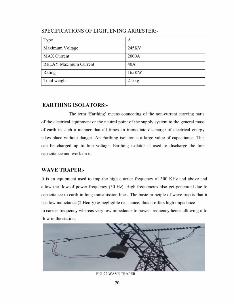
WAVE TRAPER:-
It is an equipment used to trap the high c arrier frequency of 500 KHz and above and
allow the flow of power frequency (50 Hz). High frequencies also get generated due to
capacitance to earth in long transmission lines. The basic principle of wave trap is that it
has low inductance (2 Henry) & negligible resistance, thus it offers high impedance
to carrier frequency whereas very low impedance to power frequency hence allowing it to
flow in the station.
FIG-22 WAVE TRAPER
71
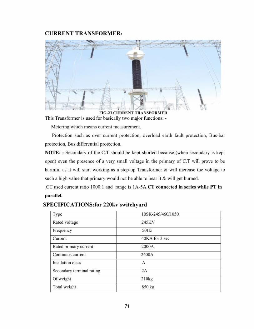
CURRENT TRANSFORMER:
FIG-23 CURRENT TRANSFORMERThis Transformer is used for basically two major functions: -
Metering which means current measurement.
Protection such as over current protection, overload earth fault protection, Bus-bar
protection, Bus differential protection.
NOTE: - Secondary of the C.T should be kept shorted because (when secondary is kept
open) even the presence of a very small voltage in the primary of C.T will prove to be
harmful as it will start working as a step-up Transformer & will increase the voltage to
such a high value that primary would not be able to bear it & will get burned.
CT used current ratio 1000:1 and range is 1A-5A.CT connected in series while PT in
parallel.
SPECIFICATIONS:for 220kv switchyardType 10SK-245/460/1050
Rated voltage 245KV
Frequency 50Hz
Current 40KA for 3 sec
Rated primary current 2000A
Continuos current 2400A
Insulation class A
Secondary terminal rating 2A
Oilweight 210kg
Total weight 850 kg

72
PIPRI LINE:
In the case of emergency, e.g. total grid failure we take the power from Pipri line for the
initial starting of the station (Main Plant).
CAPACITOR VOLTAGE TRANSFORMER(CVT)
FIG-24 CVT
This Transformer performs mainly two major functions:-
Used for voltage measurement. The high voltage of 400 KV is impossible to measure
directly. Hence a C.V.T is used, (connected in parallel with the line) which step-downs
the voltage of 400 KV to 110 KV, comparatively easy to measure.
The other most important function of C.V.T is that it blocks power frequency of 50Hz
and allows the flow of carrier frequency for communication.Each of the four line feeders
provided with three capacitor volt transformer for metering and synchronizing.
P.T (POTENTIAL TRANSFORMER):This Transformer is connected in parallel with the line with one end earthed. It is only
used for voltage measurement by stepping-down the voltage to the required measurable
value.
SPECIFICATIONS:
PARAMETERS
Type
FOR 400KV
CVE/420/1425/50
FOR 220KV
CVE/245/1050/40
HV 420KV 245KV

73
Frequency 50Hz 50Hz
Insulation level 440kv/1425KVp 440KV/1050KVp
Voltage factor 1.2 CONT/15-30 SEC 1.2 CONT/15-30 SEC
Equilant capacitor 4400+_10%, -5% P.F 4400+_10%, -5% P.F
Primary capacitor C1 4885 PF NOMINAL 4885 PF NOMINAL
Secondary capacitoe C2 4455 PF 4455 PF
Total burden/class 100VA/0.2 100VA/0.2
Thermal burden 300VA 300VA
Capacitor oil mass 50+_10%kg 50+_10%kg
Equipment oil mass 95+_10% kg 95+_10% kg
Total weight 625+_10%kg 625+_10%kg
NOMINATION OF CVT
A-NHF 1a1-1n 2a1-2n 3a1-3n
1a2-1n 2a2-2n 3a2-3n
22.98KV 63.32V 63.32V 63.32V
A
HV TERMINAL
C1 PRIMARY CAPACITOR
C2 SECONDARY CAPACITOR
NHF H F TERMINAL
L COMPENSATING CHOKE
N NEUTRAL
F1-F6 HRC FUSE
E EARTH SCREEN BETWEEN LV & HV
Zd DAMPING DEVICE
V VARISTOR
D DRAIN OIL
S SURGE ARRESTER
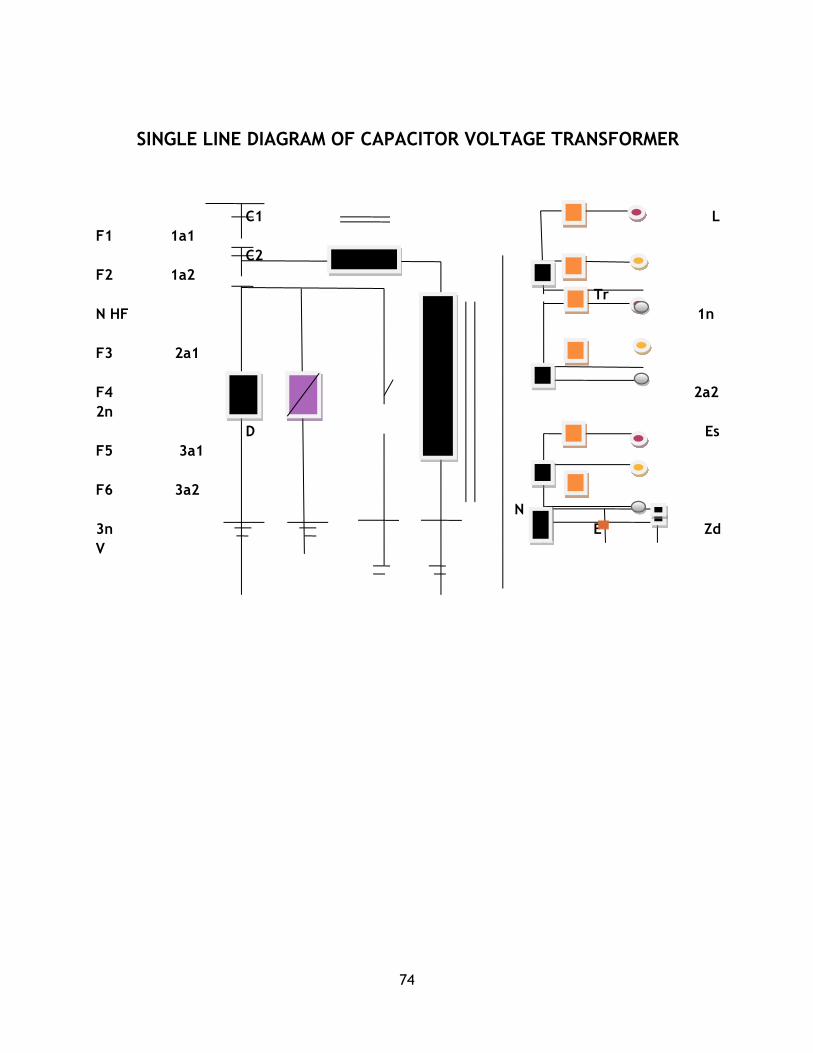
74
SINGLE LINE DIAGRAM OF CAPACITOR VOLTAGE TRANSFORMER
C1 LF1 1a1
C2F2 1a2
TrN HF 1n
F3 2a1
F4 2a22n
D S EsF5 3a1
F6 3a2N
3n E ZdV

75
INTER CONNECTED TRANSFORMER(ICT)Purpose of ICT is simply interconnection between 400KV and 220KV
Switchyard. 3xM1802-300/D-10.19.300MA2 Type autotransformer is used. manufactur
by CROMPTON GEARVES TRANSFORMER DIVISION BHOPAL.PARAMETERS
USE IN ICT:
Rating 315MVA,400/220/33KV
No load HV 400KV
Amperes LV 220KV
ONAN/ONAF/OFAF HV 272.8/363.7/454.6
LV 496.0/661.31/826.7
TV 1102/1470/1837.
Phase 3
Frequency 50Hz
Rating(MVA) ONAN ONAF ODAF
HV 189 252 315
LV 189 252 315
TV 63 84 109
Guaranted
temp.winding&oil
50 deg cel
Connection symbol YNaod11
Core+winding mass 120700kg
Total oil 71600/81800kg/ltr.
Total mass 287000kg
No load & on load
loss&auxil loss
100KW & 600KW,15KW
Impedence tolerance Hv-lv 12.55,hv-tv 45%,tv-lv 30%
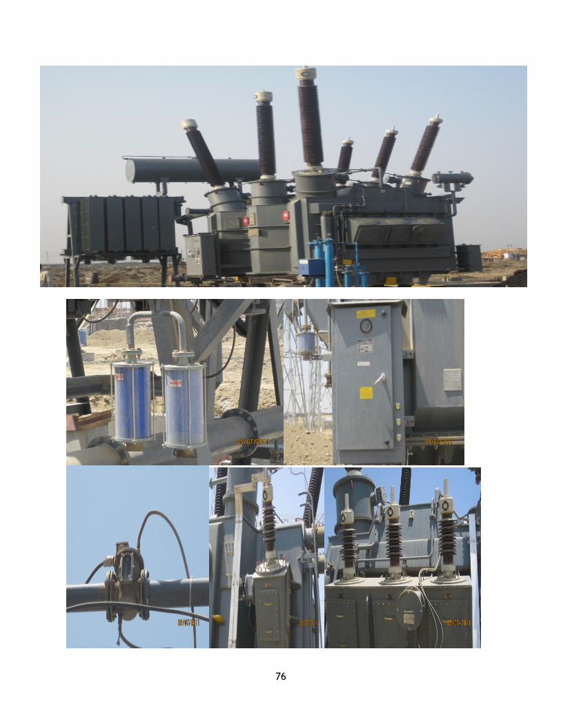
76

77
FIG-25 ICT 2 MOISTURE SENSER 3. CONTROL BOX 4 BUCHOL RELAY 5 NEUTRAL CT 6 THREE PHASECONNECTION3.2.2 SINGLE LINE DIAGRAMOF INTERCONNECTED TRANSFORMER(ICT)
TAP CHANGER AUTO TRANSFORMER FOR HV/LV/TV
N 1U1 2U1 1V1 2V1 1W1 2W1
P2 P2 P2 P2N2S1 1U11S1 1V12S1 1W11S1CORE 2 CORE1 CORE 1 CORE1N2S2 1U11S2 1V12S2 1W11S2
1V12S3CORE 21V12S4
N1S1 1V11S2CORE1 WTICT/RTD/CTN1S2 1V11S1
K K K-12 +4 -12 +4 -12 +4
HV/LV
2.1 2.1 2.1
2U12S1CORE 22U12S22U12S3CORE 22U12S42U11S2 2V11S2 2W11S2WTICT/RTD/CT CORE 2 CORE 22U11S1 2V11S1 2W11S1
2 2 2
3U1 3V1 3W1
3U11S1 3V11S1WTICT/RTD/CT CORE
TV 3U11S2 3V11S2
3U11S3CORE3U11S41 1 1
2 2 2

78
3.3 SINGLE LINE DIAGRAM FOR LINES OUTGOING FROM KaTPP
SWITCHYARD
400KV LINE-03,DAHRA(NEAR ANTA,DIST-BARAN) (BAY-12)
BUS 1
BUS 2
89-12-01 89-12-01 89-12-02 89-12-02ISO OPEN ISO CLOSE ISO OPEN ISO CLOSE
ISO ISOGRND GRND
CB OPEN CB CLOSE CB OPEN CB CLOSE
CB CB
GRND GRND
89-12-03 89-12-03 89-12-04 89-12-04ISP OPEN ISO CLOSE ISO OPEN ISO CLOSE
ISO ISO
89-12-06 89-12-06 CB OPEN CB CLOSE 89-12-05 89-12-05ISO OPEN ISO CLOSE ISO OPEN ISO CLOSE
AC SUPPLY AC SUPPLYREALY REALY
ISO CB ISO
GRND GRND
89-12-07 89-12-07 89-12-08 89-12-0ISO OPEN ISO CLOSE ISO OPEN ISO CLOSE
ISO ISO
GRND GRND
DAHRA LINE-03 (BAY -12) GT(GENERATION TRANSFORMER)-2 (BAY-14)

79
400KV LINE-01,BTAWDA (BAY-05)
BUS 1
BUS 2
89-05-01 89-05-01 89-05-02 89-05-02ISO OPEN ISO CLOSE ISO OPEN ISO CLOSE
ISO ISOGRND GRND
CB OPEN CB CLOSE CB OPEN CB CLOSE
CB CB
GRND GRND
89-05-03 89-05-03 89-05-04 89-05-04ISP OPEN ISO CLOSE ISO OPEN ISO CLOSE
ISO ISO
89-05-06 89-05-06 CB OPEN CB CLOSE 89-05-05 89-05-05ISO OPEN ISO CLOSE ISO OPEN ISO CLOSE
ISO
ISO CB ISO
CB GRND GRND
89-05-07 89-05-07 89-05-08 89-05-08ISO OPEN ISO CLOSE ISO OPEN ISO CLOSE
ISOISO ISO
GRND GRND
REACTOR
GT(GENERATION TRANSFORMER)-1(BAY-07)
REACTOR BAY -04
BTAWDA LINE-01(BAY-05)
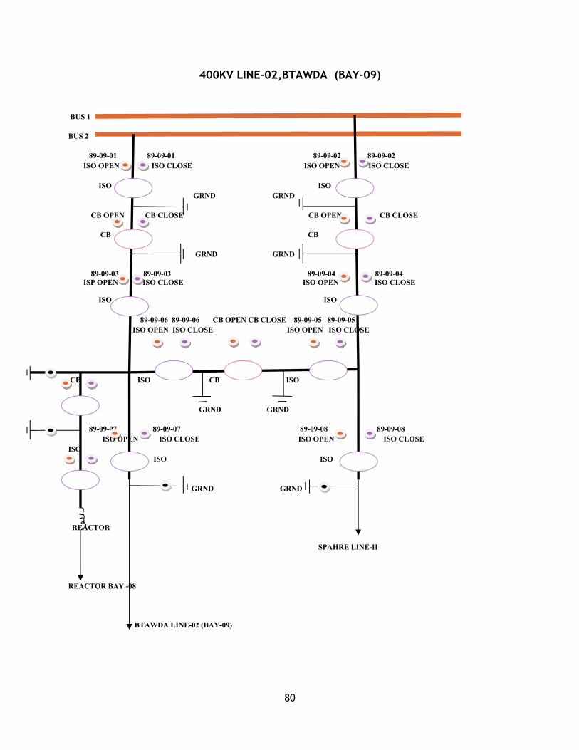
80
400KV LINE-02,BTAWDA (BAY-09)
BUS 1
BUS 2
89-09-01 89-09-01 89-09-02 89-09-02ISO OPEN ISO CLOSE ISO OPEN ISO CLOSE
ISO ISOGRND GRND
CB OPEN CB CLOSE CB OPEN CB CLOSE
CB CB
GRND GRND
89-09-03 89-09-03 89-09-04 89-09-04ISP OPEN ISO CLOSE ISO OPEN ISO CLOSE
ISO ISO
89-09-06 89-09-06 CB OPEN CB CLOSE 89-09-05 89-09-05ISO OPEN ISO CLOSE ISO OPEN ISO CLOSE
CB ISO CB ISO
GRND GRND
89-09-07 89-09-07 89-09-08 89-09-08ISO OPEN ISO CLOSE ISO OPEN ISO CLOSE
ISOISO ISO
GRND GRND
REACTOR
SPAHRE LINE-II
REACTOR BAY -08
BTAWDA LINE-02 (BAY-09)

81
400KV SPARE LINE, (BAY-01)
BUS 1
BUS 2
89-01-01 89-01-01 89-01-02 89-01-02ISO OPEN ISO CLOSE ISO OPEN ISO CLOSE GRND
ISO ISOGRND GRND
CB OPEN CB CLOSE CB OPEN CB CLOSE
CB CB ISO
GRND GRND
89-01-03 89-01-03 89-01-04 89-01-04 GRNDISP OPEN ISO CLOSE ISO OPEN ISO CLOSE
ISO ISO
89-01-06 89-01-06 CB OPEN CB CLOSE 89-01-05 89-01-05ISO OPEN ISO CLOSE ISO OPEN ISO CLOSE
CVT BUS -01
CB ISO CB ISO
GRND GRND
89-01-07 89-01-07 89-01-08 89-01-08ISO OPEN ISO CLOSE ISO OPEN ISO CLOSE
ISO ISO
GRND GRND
CVT BUS-02
SPAHRE LINE,BAY-01
315 MVA ICT ,BAY-03

82
400KV TIE LINE, (BAY-02)
BUS 1
BUS 2
89-02-01 89-02-01 89-02-02 89-02-02ISO OPEN ISO CLOSE ISO OPEN ISO CLOSE GRND
ISO ISOGRND GRND
CB OPEN CB CLOSE CB OPEN CB CLOSE
CB CB ISO
GRND GRND
89-02-03 89-02-03 89-02-04 89-02-04 GRNDISP OPEN ISO CLOSE ISO OPEN ISO CLOSE
ISO ISO
89-02-06 89-02-06 CB OPEN CB CLOSE 89-02-05 89-02-05ISO OPEN ISO CLOSE ISO OPEN ISO CLOSE
CVT BUS -01
CB ISO CB ISO
GRND GRND
89-02-07 89-02-07 89-02-08 89-02-08ISO OPEN ISO CLOSE ISO OPEN ISO CLOSE
ISO ISO
GRND GRND
CVT BUS-02
TIE LINE,BAY-02
315 MVA ICT ,BAY-04

83
400KV ICT LINE , (BAY-03)
BUS 1
BUS 2
89-03-01 89-03-01 89-03-02 89-03-02ISO OPEN ISO CLOSE ISO OPEN ISO CLOSE GRND
ISO ISOGRND GRND
CB OPEN CB CLOSE CB OPEN CB CLOSE
CB CB ISO
GRND GRND
89-03-03 89-03-03 89-03-04 89-03-04 GRNDISP OPEN ISO CLOSE ISO OPEN ISO CLOSE
ISO ISO
89-03-06 89-03-06 CB OPEN CB CLOSE 89-03-05 89-03-05ISO OPEN ISO CLOSE ISO OPEN ISO CLOSE
CVT BUS -01
CB ISO CB ISO
GRND GRND
89-03-07 89-03-07 89-03-08 89-03-08ISO OPEN ISO CLOSE ISO OPEN ISO CLOSE
ISO ISO
GRND GRND
CVT BUS-02
ICT , BAY-03
315 MVA ICT ,BAY-05

84
220KV LINE -01 JHALAWAR (BAY -01)
BUS 1
BUS2
89-01-01 89-01-01 89-01-02 89-01-02
ISO OPEN ISO CLOSE ISO OPEN ISO CLOSE
ISOLATOR ISOLATOR
GAND GRND
CB LOCAL CB REMOTE CB OPEN CB CLOSE CB SPRING CHARGED
CIRCUIT BREAKER
89-01-03 89-01-03
ISO OPEN ISO CLOSE
ISO
GRND
89-01-04 89-01-04
ISO OPEN ISO CLOSE
ISO
TRANSFER BUS
220KV LINE-01JHALAWAR

85
220KV LINE-02 JHALAWAR (BAY -03)
BUS 1
BUS2
89-03-01 89-03-01 89-03-02 89-03-02
ISO OPEN ISO CLOSE ISO OPEN ISO CLOSE
ISOLATOR ISOLATOR
GAND GRND
CB LOCAL CB REMOTE CB OPEN CB CLOSE CB SPRING CHARGED
CIRCUIT BREAKER
89-03-03 89-03-03
ISO OPEN ISO CLOSE
ISO
GRND
89-03-04 89-03-04
ISO OPEN ISO CLOSE
ISO
TRANSFER BUS
220KV LINE-02JHALAWAR

86
220KV ICT(INTER CONNECTED TRANSFORMER) BAY -02
BUS 1
BUS2
89-02-01 89-02-01 89-02-02 89-02-02
ISO OPEN ISO CLOSE ISO OPEN ISO CLOSE
ISOLATOR ISOLATOR
GAND GRND
CB LOCAL CB REMOTE CB OPEN CB CLOSE CB SPRING CHARGED
CIRCUIT BREAKER
89-02-03 89-02-03
ISO OPEN ISO CLOSE
ISO
GRND
89-02-04 89-02-04
ISO OPEN ISO CLOSE
ISO
TRANSFER BUS
220KVLINE ICT

87
220 KV BUS COUPLER(BAY-05)
BUS 1
BUS 2
BUS 1 CVTBUS 2 CVT
89-05-01 89-05-01 89-05-02 89-05 -02ISO OPEN ISO CLOSE ISO OPEN ISOCLOSE
ISO ISO
GRNDGRND
CB LOCAL CB REMOTE CB OPEN CB CLOSE CB SPRINGCHARGED
CIRCUIT BREAKER
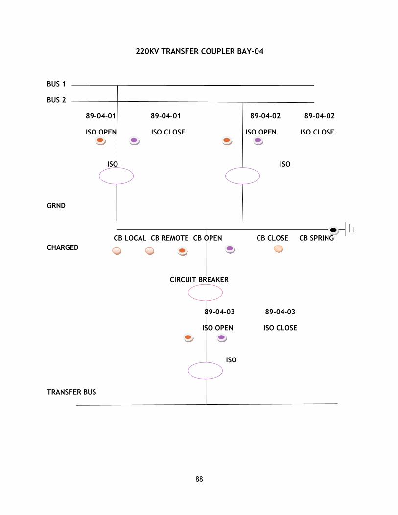
88
220KV TRANSFER COUPLER BAY-04
BUS 1
BUS 2
89-04-01 89-04-01 89-04-02 89-04-02
ISO OPEN ISO CLOSE ISO OPEN ISO CLOSE
ISO ISO
GRND
CB LOCAL CB REMOTE CB OPEN CB CLOSE CB SPRINGCHARGED
CIRCUIT BREAKER
89-04-03 89-04-03
ISO OPEN ISO CLOSE
ISO
TRANSFER BUS

89
7.2 CONTROL & INSTRUMENTATION SYSTEM
7.2.1 SWITCHGEARThe apparatus used for switching, controlling and protecting the electrical
circuits and equipment is known as switchgear.
A switch gear is one which makes or breaks electric circuit. Numerous
problems arise in erection, testing and commissioning of switch gear and various
precautions are to be made in operating and maintenance of switch gear.
Essential Features of Switch Gear:-Complete Reliability
Absolutely certain discrimination
Quick operation
Provision for manual control
provision for instruments
The main components of indoor switchgear are given below:-
i.Bus-Bars
ii.Isolating Switches
iii.Current Transformers
iv.Potential Transformers
v.Circuit Breaker
vi.Earthing arrangement
vii.Relays
viii.Inter-Locking arrangements
(i) BUS-BARS:-Bus bars are defined as the conductors to which several incoming and
outgoing lines are connected. They are essential component of Switchgear. They are
made up of Cu. and Al. The type and designers of Switchgear depends upon rated
normal current and short circuit capacity. The Bus bars are enclosed in bus bar chamber.
In KaTPP there are two types of indoor switch gear:
11 KV &3.3KV or High tension

90
3.415V or Low tension
(ii) ISOLATING SWITCHING:-1. They are capable of-Interrupting the Transformer Magnetizing Current.Interrupting
line charging Current.Interrupting load Transformer Switching.
2. The main application is in connection with feed or bank Transformer feeders & there
units make it possible to switch out one Transformer while the other is still on load.
(iii) CIRCUIT BREAKER:-They are capable of breaking the circuit on faults. It is heavy duty
equipment mainly utilized for protection of various circuit and separation of loads.
The Circuit Breaker uses on a relay or by manual signal. The Circuit
Breakers which are used in Switchgear are VCB type.
(iv) EARTHED SWITCHES:-Earthed switch is connected between line conductor and earth. Normally
it is open when line is disconnected. The Earthing switched is closed so as to discharge
the voltage trapped on line for high voltage and so the capacitor between line and earth
is charged to high voltage. For maintenance work their voltage are discharged to earth
by closing the earth switch.
(vi) INTER-LOCKING:-The following type of inter- locking are provided
The Circuit Breaker must be in open position before it is lowered in this position.
The Circuit Breaker can be closed only raising the final plug in position.
The Circuit Breaker can be closed before raising plug in position.
Inter-locking between isolators, Earthing switches and Circuit Breakers are provided.
(vii) RELAYS:-A Protective Relay is a device that detects the fault and initiates the
operation of the circuit breaker to isolate the defective element from the rest of the
system.

91
7.2.2 PROTECTIONThe fault, which may occur in stator winding are-
1. Phase to phase fault.
2. Phase to ground fault.
3. Line to line fault.
4. Over heating.
These faults are due to-
1. Over voltage is because of system transients, lightening switching surges or sudden
loss of load.
2. Insulation deterioration due to any matter, moisture, corona discharge, Hardening of
solid and vibration.
It is very necessary to minimize the tripping time during any fault so that the lamination
is not damaged. The repairing being affected by replacing the faulty stator bar.A
delayed clearance may damage the lamination, so fire may be caused and partial re-
insulation of core may be necessary.
GENERATOR PROTECTION:-The Generator is required to be tripped or isolated on following types of fault:
1. Failure of generating insulation.
2. Failure of prime mover turbine or boiler.
3. Failure of generating auxiliaries such as hydrogen gas system,seal oil
system, cooling system, and cooling water system.
4. Failure of grid.
The tripping command to the GT breaker is given by master trip relay 866,
86GT, and 86GB. To make it feasible the master trip relay is connected to a common
bus. All the protection relays are connected in between the position of 220V.
D.C. PROTECTION AND THE COMMON BUS:-Protection device are that detect abnormal condition in electrical circuit
by measuring the electrical quantity which are different under normal and fault
condition. The basic electrical quantities are voltage, current, phase angle and frequency.

92
The relay doesn’t operate for normal voltage, normal current, normal phase angle and
normal frequency.
Different type of protection can be listed as:
1. Current operated protection.
2. Different protection.
3. Voltage operated protection.
4. Impedance type protection.
5. Frequency type protection.
1. CURRENT OPERATED PROTECTION:-a. Generator differential protection.
b. Generator negative sequence protection.
c. Generator output current protection.
d. Generator stator earth fault protection.
e. Generator REF protection.
f. Generator standby earth fault protection.
g. UAT o/c protection.
h. Generator o/c and short circuit protection.
i. L.B.B. protection.
2. DIFFERENTIAL PROTECTION:-a. Generator overall differential protection.
b. UAT differential protection.
3. VOLTAGE OPERATED PROTECTION:-a. Generator over voltage protection.
b. Generator stator E/F protection.
c. GT over voltage protection.
d. PT’s voltage supervision protection.
e. Generator inter-turn fault protection.
4. IMPEDANCE TYPE PROTECTION:-a. Generator back up impedance protection.
b. Generator loss of exact protection.
c. Generator pole slip protection.
5. FREQUENCY TYPE PROTECTION:-a. Generator under protection Frequency.
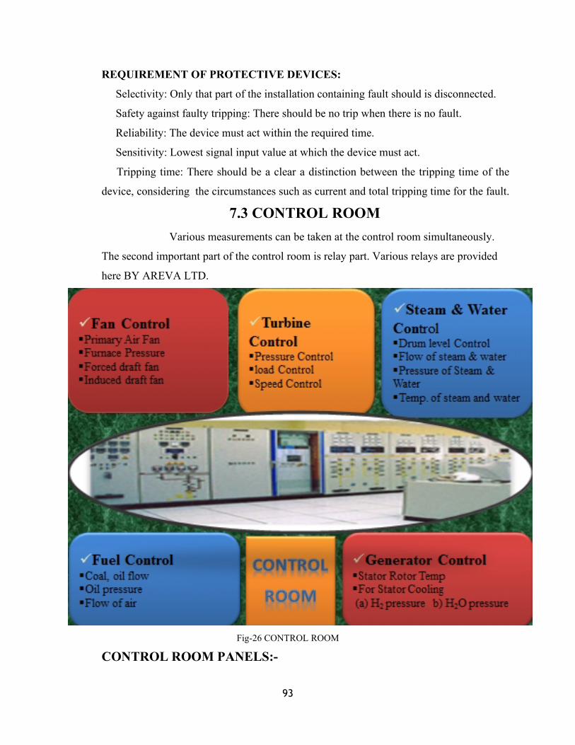
93
REQUIREMENT OF PROTECTIVE DEVICES:
Selectivity: Only that part of the installation containing fault should is disconnected.
Safety against faulty tripping: There should be no trip when there is no fault.
Reliability: The device must act within the required time.
Sensitivity: Lowest signal input value at which the device must act.
Tripping time: There should be a clear a distinction between the tripping time of the
device, considering the circumstances such as current and total tripping time for the fault.
7.3 CONTROL ROOMVarious measurements can be taken at the control room simultaneously.
The second important part of the control room is relay part. Various relays are provided
here BY AREVA LTD.
Fig-26 CONTROL ROOM
CONTROL ROOM PANELS:-
94
FAN CONTROL DESK: -
ID Fan (Induced draft fan, 2nos.) at full load.
FD Fan (Forced draft fan, 2nos.) at full load.
PA Fan (Primary air fan, 2 nos.) at full load.
PRESSURE CONTROL DESK: -Furnace pressure (5-10mmwcl.)
Primary air header pressure (750-800mmwcl).
1. FUEL CONTROL DESK:-
Coal oil flow.
Oil pressure.
Temperature of mill (inlet or outlet)
Flow of air.
Drum level control, flow of steam water
Pressure of steam and water.
Temperature of steam and water.
1. TURBINE DESK:-
Pressure control, load mode control.
Speed control.
Ejector, control valves, stops valves and deviators.
1. GENERATOR CONTROL PANEL:-
Voltage, current, MVAR.
Stator, rotor temperature.
For stator cooling.
7.4 AUXILIARY SUPPLY

95
Electrical supply system is the most important part of the thermal power
station. The failure of even comparatively small equipment could result in the losing of
load or being put out of commission.
SOURCE OF SUPPLY: -
1. URGENT AUXILLARY: -
Those are associated with running of units whose loss would cause an
immediate reduction unit output.
2. SERVICE AUXILLARY: -
These are common auxiliaries associated with one or more units. There
loss would not affect the output of the unit after considerable time of interval.
ELECTRICAL AUXILLARY SYSTEM: -The KaTPP auxiliaries are operated at two voltages that are 6.6 KV and
415V. In respect of 6.6KV system, auto change over facility is provided for change over
of source of supply from unit station in the case of unit trip out. The station is having
the following auxiliary system: -
More then 1500KW connected on 11KV.
More then 200KW less then 1500KW connected on 3.3KV.
Less then 200KW on 415V.
220V D.C. underground system for use in control and protection system.
3.3 KV SYSTEM: -
For the running unit, the unit auxiliaries are normally fed from gen’r
itself through 11/3.3 KV, 15 MVA unit auxiliary transformers, which is, connected to
the unit switchgear viz. USA and USB. Power to station auxiliaries and by unit
auxiliary is fed from 220/3.3KV, 50 MVA station transformers through two switchgear
viz.
415 V SYSTEMS: -
For driving ten 100W motors and other accessories, we need 415V
supply. For this purpose various transformer are used to step down 3.3 KV to 415V at
various places. Oil circuit breaker is provided between 3.3 KV bus and primary winding
of transformer.
96
This system is three phase, 4-wire solidly grounded system is made
available for 1000 KVA, 3.3 KV/ 433V transformer.
240 V SYSTEMS: -240 V, 50 HZ. System is provided for control circuits of contactors
modular of all 415 V switchgear or MCC space heating of various switchgears and
space heating of all motor above 37.5 KW rating. Each of modules with power
contactor.
415 V /24 V SYSTEMS: -24 V, 50 HZ. Supply is used for winding heating of motors
up to 37.5 KW. This is made available by one or more 1- 415 V/24 V, 4 KVA
transformers. Three transformers are provided with 415 V switchgear/MCB.
400 KV SYSTEMS: - Two 400 KV buses have been provided in switchyard and
are inter connected through a bus coupler. Each of the 2X600 MW generators are
connected to this system through a step up 150/200/250MVA generator.
220 V D.C. SYSTEMS: -
The station 220V D.C. system is used for control, interlocks, and
protection indication and annunciation circuit of various equipments. In addition some
critical unit and station auxiliary also operate on 220 V D.C. e.g. D.C. emergency oil
pump for turbine lubrication D.C. lightning etc.
CHAPTER-08,EFFICIENCY & CONCLUSION

97
8.1. EFFICIENCY
In KaTPP we convert potential energy or chemical energy of the fuel
into heat by the process of combustion. The heat is given to the water and it converts its
form into steam. The pressure of steam rotates the turbine, which is now in the form of
kinetic energy. Generator producing electrical energy, which is sand to different
localities for utilization, consumes this kinetic energy.
Enthalpy is defined as the thermodynamic property of a system, is equal
to the sum of its internal energy and the product of its pressure and volume.
Enthalpy is an ancient Greek word meaning evolution and many
eminent scholars have been attempted to define it. It is a mathematical concept of
available energy in the steam.
Efficiency in the case of electrical generator process can be expressed as
the amount of heat energy librated in the boiler compared with the amount of electrical
energy generated with it.
PLANT EFFICIENCY: -We will divide whole plant efficiency in four-component efficiency:
(1). Cycle efficiency
(2). Turbo generator efficiency
(3). Boiler efficiency
(4). Auxiliary power efficiency
Overall = Boiler x Turbine x Cycle x Generator
1. CYCLE EFFICIENCY: -
Cycle efficiency being the maximum possible heat energy that
could be obtained from any particular set of steam conditions employed. The operation
of heat reduction of condenser, which is almost 50% of the total available heat, makes
ranking cycle relatively inefficient.
It can be controlled by: -
(a). Condenser vacuum.
(b). Steam conditions of CV and LV
(c). Regenerative feed heating.
Cycle = energy available for conversion in work
Energy given in boiler as heat
98
2. ALTERNATOR EFFICIENCY: - The alternator is a efficient machine at about 98
% efficiency. The losses are:
(a). Copper and iron loss
(b). Wind age losses
Operationally the plant is governed by the grid requirements. For voltage we use
the set out from generator transformer.
3. BOILER EFFICIENCY: - It depends upon:
(a). Dry flue gas loss: Increase by excess air in boiler.
(b). Wet flue gas loss: Moisture in coal.
(c). Moisture in combustion loss: Hydrogen loss.
(d). Radiator and in accounted loss.
4. TURBINE EFFICIENCY: -It means the efficiency of steam turbine in converting
the heat energy made available in the cycle into actual mechanical work.
Turbine losses falls into one or two groups either losses external to the turbine or losses
directly related to the expansion of the steam in the cylinder.
8.2 CONCLUSION

99
The first phase of Practical Training has proved to be quite fruitful. It
provides an opportunity for encounter with such huge machines like wagon tippler,
600MW Turbines and Generators.
The architecture of the power plant, the way various units are linked and
the way working of whole plant is controlled make the student realize that engineering
is not just learning the structure description and working of various machine but the
great part is of planning proper management.
It also provides an opportunity to lean low technology used at proper
place and time can cave a lot of labor.
But there are few factors that require special mention. Training is not
carried to its true spirit. It is recommended that there should be some project specially
meant for students where presence of authority should be ensured. There should be
strict monitoring of the performance of students and system of grading be improved on
basis of work done.
However training has proved to be quite fruitful. It has allowed an
opportunity to get an exposure of the practical implementation to theoretical
fundamentals.
REFERENCECHAPTER-09
100
[1].www.rrvunl.com
[2].www.energyindia.com
[3].www.googleindia.com
[4].www.thermalpower.com
[5].www.scibe.com
[6].Fundamentals of electrical engineering/power plant/tpp/655 ,Ashfaq Husain
Dhanpat Rai &Co.
[7].Generation of electrical power/thermal station, B R Gupta ,S.CHAND
PUBLICATION.
[8].EPC Book Volume-V,TCE 5248.A-H-500-001
[9].Annual Report o f TCE Ltd.
[10]. Single Line Diagram GID-118-EL-XJ-2012,BGR REPORT ON
KaTPP.
[11]. Single line diagram KaTPP Plan GID-2012,BGR ENERGY SYSTEM.
[12]. PPT On Thermal Plant/TCE/M Shreenivashan/104840/.
[13]. Assignment Shreenivashan /Tce /104840