trajectory analysis for the masar: a new modular and
TRANSCRIPT

robotics
Article
Trajectory Analysis for the MASAR: A New Modularand Single-Actuator Robot
Adrián Peidró *,† , Julio Gallego †, Luis Payá † , José María Marín † and Óscar Reinoso †
Automation, Robotics, and Computer Vision laboratory, Miguel Hernández University, 03202 Elche, Spain;[email protected] (J.G.); [email protected] (L.P.); [email protected] (J.M.M.); [email protected] (Ó.R.)* Correspondence: [email protected]† These authors contributed equally to this work.
Received: 14 July 2019; Accepted: 2 September 2019; Published: 5 September 2019�����������������
Abstract: Single-actuator mobile robots offer the benefits of low energy consumption, low weightand size, and low cost, but their motion is typically only one-dimensional. By using auxiliary binarymechanisms that redirect and channel the driving force of their only actuator in different ways,it is possible for these robots to perform higher-dimensional motions, such as walking straight,steering, or jumping, with only one motor. This paper presents the MASAR, a new Modular AndSingle-Actuator Robot that carries a single motor and several adhesion pads. By alternately releasingor attaching these adhesion pads to the environment, the proposed robot is able to pivot aboutdifferent axes using only one motor, with the possibility of performing concave plane transitions orcombining with other identical modules to build more complex reconfigurable robots. In this paper,we solve the planar trajectory tracking problem of this robot for polygonal paths made up of sequencesof segments, which may include narrow corridors that are difficult to traverse. We propose alocomotion based on performing rotations of 180◦, which we demonstrate to be the minimum-timesolution for long trajectories, and a near-optimal solution for shorter ones.
Keywords: single-actuator robots; trajectory planning; climbing robots; modular robots; alternating pivot;adhesion pads
1. Introduction
Single-Actuator Mobile Robots (SAMR) are robots with the ability to explore environments withrelatively high freedom using only one motor. The most direct consequences and advantages ofusing a single actuator are savings in costs, energy consumption, size, and weight. Due to theseadvantages, SAMR robots are especially appropriate for applications that require energy autonomy,miniaturization, and navigation in difficult-to-access areas, with the purpose of performing inspection,cleaning, reconnaissance or search-and-rescue tasks, among others [1].
Most SAMR robots reported in the specialized literature can be classified into one of three maintypes (type-I, type-II, or type-III), depending on two criteria: the dimension of their workspace,and the existence of auxiliary binary mechanisms that help the robot to change the direction of motion.This classification, which we propose in this paper, is illustrated in Figure 1.
Type-I SAMR are robots that use a single actuator to control their motion along a one-dimensionalworkspace, with no additional mechanisms. For example, the authors in [2] presents an octopod thatcan walk forward or backwards along a straight line by means of a single motor and a system of camsthat synchronize the motion of all its eight legs. Similarly, the authors in [3,4] present two climbingrobots that can vertically climb using a single actuator each. Another single-actuator climbing robot ispresented in [5]; this robot swings a pendulum to dynamically climb the vertical space between twowalls by bouncing between these walls. The authors in [6] present a robot that can climb or move along
Robotics 2019, 8, 78; doi:10.3390/robotics8030078 www.mdpi.com/journal/robotics

Robotics 2019, 8, 78 2 of 22
a straight line by using a wave-like locomotion generated by a single motor. Type-I SAMR robots canonly move along one dimension. In order for these robots to be able to change the direction of theirmotion and control their motion in higher-dimensional workspaces (e.g., plane or space), it would benecessary to equip them with additional motors [4,6], and thus they would no longer be single-actuatormobile robots.
Type-I Type-III
Type-II
Dimension of workspace1 > 1
Has
aux
ilia
ry b
inar
y m
echa
nism
s?Y
esN
o
Input signal:
Turn Straight motion
1
2
34
(No practical interest)
Figure 1. Classification of single-actuator mobile robots.
According to Figure 1, type-II SAMR have workspaces with dimensions higher than one, i.e., theyare not constrained to move along a straight line only, but they can typically control their positionand orientation in a plane. In addition to having a main continuous actuator, type-II SAMR arecharacterized by having also some additional binary mechanisms that allow the robot to modify itstopology, changing in this way the effect that its single main actuator exerts on the overall motion ofthe robot. In other words: strictly speaking, type-II SAMR robots should be called “Single-ActuatorMobile Robots. . . with auxiliary binary actuators” (nevertheless, some authors of these robots regardthem as single-actuated). Thanks to these auxiliary binary actuators, the driving force generatedby the only continuous actuator of the robot can be channeled as required, e.g., to produce straightmotion, to change the direction of motion, to jump, etc. Note that these auxiliary binary actuators donot necessarily need to be motors or actuators in the usual sense of the term, but they can simply beelectromagnets, suction cups, or clutches that engage or disengage two mobile parts of some internalmechanism of the robot, in order to transmit the driving force of the only continuous actuator todifferent mechanisms and modify the overall motion of the mobile robot.
Some examples of type-II SAMR robots can be found in the literature. For example, the authorsin [7] present a mobile robot with two variable-radius wheels driven by a single motor such that,when activating a clutch, this motor also displaces the center of mass of the robot along its main shaft,which modifies the relative radii of the wheels and produces a change in the direction of motion dueto differential drive kinematics. The authors in [8,9] propose snake-like robots powered by a singletendon-driven actuator each robot. These robots are made up of several segments rigidly connected bywelded joints such that, when applying an electric current to some of these welds, can temporarilymelt them in order to modify the geometry of the robots. By selectively melting these welded jointsand actuating their only motor, these robots can move along straight lines, change their direction in aplane, or perform out-of-plane motions. Finally, the authors in [10] present the DynaRoACH robot,which is inspired by cockroaches and has a single actuator to move along straight lines. This robot canalso turn by modifying the relative stiffness of its legs through shape-memory alloys. Similarly, theDASH robot [11] is a single-motor hexapod that can steer or walk straight by respectively introducingor removing small asymmetries between its legs, by means of shape-memory alloys.

Robotics 2019, 8, 78 3 of 22
Type-III SAMR typically are under-actuated mobile robots that use a single actuator and lackauxiliary binary mechanisms, and they are able to control their motion in more than one dimension.Usually, these robots will perform some type of motion or other (e.g., moving along a straight line,turning, jumping. . . ) depending on the characteristics (amplitude, sign, frequency. . . ) of the inputsignal applied to its only actuator. For example: [12] presents a robot that swims over water surfaces,this robot is driven by a single actuator that produces straight motion when excited at constantfrequency, whereas it modifies the direction of motion when being excited at different frequenciesduring each semi-period. The authors in [13] develop a micro-robot made up of a single piezoelectricactuator that makes the robot move in straight lines or turn left/right depending on the naturalfrequency at which this actuator is excited. A similar cubic robot is presented in [14], where therobot can move straight or turn by exciting its only actuator (a dielectric elastomer resonator) atdifferent resonant frequencies. Zuliani et al. [15] developed an origami hand that can adopt differentconfigurations (with different fingers extended or folded) depending on the excitation frequency ofits only actuator. Although this is not a mobile robot, the idea might be exploited to build small andlightweight single-actuated legged origami robots. In [16], a spherical robot is proposed, which isable to either move straight or steer by rotating its only internal motor at constant or alternatingvelocity, respectively. The authors in [1] present a single-actuated hexapod robot whose legs havedifferent stiffnesses; this robot will walk in straight lines or turn left/right depending on the shape ofthe velocity profile introduced to its only motor. Ribas et al. [17] designed a single-motor tricycle robotthat can steer and move forward describing undulatory trajectories by pivoting alternatively abouteach of the rear wheels, similar to our robot proposed in the present paper. The front wheel of thistricycle can freely steer, displacing the instantaneous center of rotation from one rear wheel to the otherby inverting the spin of the motor. In [18], a robot consisting of a single large wheel with only onemotor is presented: if this motor oscillates between two limit positions, the robot rolls along a straightline. If the motor overcomes one of such limits, then a spring is compressed and its elastic energyis suddenly released, which produces the jump of the robot to overcome steps and other obstacles.Finally, the authors in [19,20] present jumper robots that can perform different movements using onlyone motor: jumping (by compressing springs), standing up after the jump, modifying the direction ofthe next jump, or panning a camera mounted on the robot. These robots will perform some or othermotions depending on the amplitude and sign of the rotation of their only motors.
Comparing the three types of SAMR robots identified, generally one of the main drawbacks oftype-III SAMR is that it may be difficult to precisely control their motion [1], since it largely dependson their under-actuated dynamics. On the contrary, it is relatively easy to precisely control the motionof type-II SAMR robots by using their auxiliary binary actuators. Type-I robots are usually simpler butthey can only move along one dimension. Note that the bottom-left cell in the classification table ofFigure 1 is empty because it would not have much practical interest to design SAMR robots that haveauxiliary binary mechanisms but can only move along one-dimensional workspaces (the purpose ofthese binary mechanisms is precisely to increase the dimension of the workspace).
Acknowledging the higher simplicity and flexibility of type-II SAMR robots, this paper presentsthe MASAR: a new Modular And Single-Actuator Robot that explores two-dimensional environmentsby rotating about binary pivots that are alternately adhered to the environment or detached asrequired, as illustrated schematically in the bottom-right cell of Figure 1. Contrary to previous type-IISAMR, the proposed robot is capable of performing concave transitions between orthogonal planes,which makes it especially suitable for exploring indoor environments delimited by floors, walls, andceilings. In addition, the proposed robot can combine with other identical modules in order to formmore complex modular reconfigurable robots. This paper focuses on the trajectory analysis of theproposed robot, in order to follow polygonal paths composed of chains of straight segments that mayinclude narrow sections that constrain the movements of the robot.
This paper is organized as follows. First, Section 2 presents the proposed MASAR robot.Then, Section 3 solves its path tracking problem in the case of polygonal paths with narrow sections

Robotics 2019, 8, 78 4 of 22
that must be traversed. Next, Section 4 illustrates the proposed path tracking solution with someexamples and experiments that deepen into the problem. Finally, Section 5 presents the conclusionsand future work.
2. MASAR: A New Modular And Single-Actuator Robot
This section presents a new type-II SAMR robot, whose trajectory analysis is the main focus ofthe present paper. This robot is depicted in Figure 2a, and it has been called MASAR, which is theacronym of “Modular And Single-Actuator Robot”. MASAR is patented with Ref. number ES2684377and priority date 31 March 2017.
B
M
Side view:
ECD1D2
D3
D4
D6
D5A3
E4
A4
A1 A5A2
A6
E6
Top view:
M
A1 A2
A3 A5
E3 E5
EC
BD3 D5
D4 D6D1 D2 = free adhesion pad (not adhered to floor)
= fixed adhesion pad (adhered to floor)
A4
A6
A4
A6
A4A6
(b) (c) (d)
(a)
…
Figure 2. (a) the MASAR, a Modular And Single-Actuator Robot. (b–d) locomotion of the MASAR.
As illustrated in Figure 2a, MASAR has a main body B rigidly attached to a single motor M thatdrives a central shaft EC that can rotate with respect to body B. At each side of the motor M, there isa mechanism comprised of three bevel gears with mutually orthogonal and intersecting axes: gearsD1, D3, D4 to the left of M, and gears D2, D5, D6 to the right. Gears D3, D4, D5, D6 are connected torespective small shafts E3, E4, E5, E6 that can rotate with respect to the main body B; these axes haveadhesion pads A3, A4, A5, A6 at their ends (see Figure 2a). Likewise, the central shaft EC has adhesionpads A1, A2 at both ends.
According to the classification of Figure 1, MASAR is a type-II SAMR robot because it hasseveral binary adhesion pads (A1, A2, A3. . . ), each of which may be ON or OFF (i.e., adhered to theenvironment or not adhered to it, respectively). The locomotion of this robot is as follows. Assumethat the robot is initially resting on the floor through pads A4 and A6, as in the previous Figure 2a.Assume also that only pad A4 is ON (i.e., adhered to the floor). When actuating motor M in thissituation, since A4 is rigidly adhered to the floor, the central shaft EC (and the whole robot, as aconsequence) will rotate about the axis of E4, since the bevel gear D1 will roll on gear D4, which isstatic because A4 is adhered to the floor. This motion is illustrated in Figure 2b, which representsschematically a top view of the robot. After rotating the robot about E4, the adhesion pad A6 would beturned ON, whereas A4 would be turned OFF, and powering the motor in that case would produce therotation of the whole robot about axis E6, as indicated in Figure 2c. By alternately turning ON and OFFpads A4 and A6, the robot would walk on the floor describing some desired trajectory (see Figure 2dor Figure 1).
Regarding the adhesion pads, the technology to implement them should not be different fromother adhesion technologies generally used in climbing robots. Of all adhesion technologies usedin climbing robots [21], magnetic and pneumatic technologies are the most mature and widely usedones, and these should be the adhesion technologies used for the adhesion pads of the MASAR robot.The choice to use one or another technology will depend on the medium on which the robot moves:
Robotics 2019, 8, 78 5 of 22
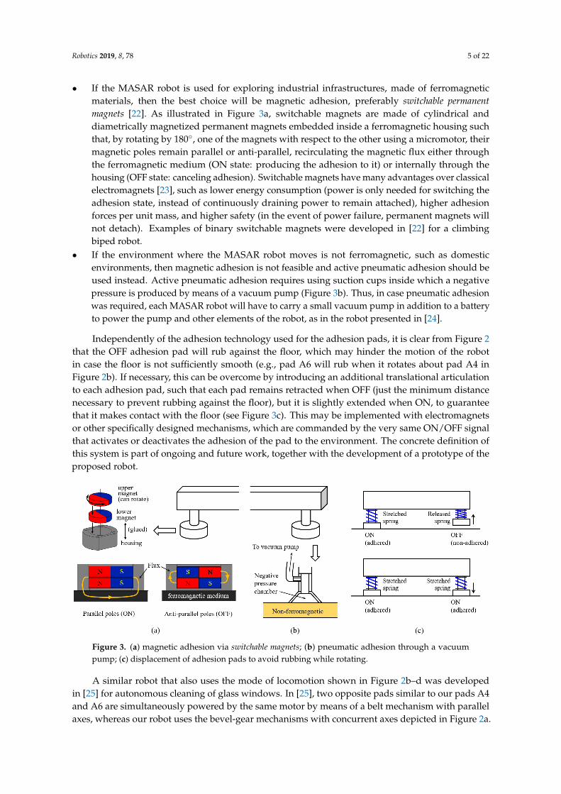
• If the MASAR robot is used for exploring industrial infrastructures, made of ferromagneticmaterials, then the best choice will be magnetic adhesion, preferably switchable permanentmagnets [22]. As illustrated in Figure 3a, switchable magnets are made of cylindrical anddiametrically magnetized permanent magnets embedded inside a ferromagnetic housing suchthat, by rotating by 180◦, one of the magnets with respect to the other using a micromotor, theirmagnetic poles remain parallel or anti-parallel, recirculating the magnetic flux either throughthe ferromagnetic medium (ON state: producing the adhesion to it) or internally through thehousing (OFF state: canceling adhesion). Switchable magnets have many advantages over classicalelectromagnets [23], such as lower energy consumption (power is only needed for switching theadhesion state, instead of continuously draining power to remain attached), higher adhesionforces per unit mass, and higher safety (in the event of power failure, permanent magnets willnot detach). Examples of binary switchable magnets were developed in [22] for a climbingbiped robot.
• If the environment where the MASAR robot moves is not ferromagnetic, such as domesticenvironments, then magnetic adhesion is not feasible and active pneumatic adhesion should beused instead. Active pneumatic adhesion requires using suction cups inside which a negativepressure is produced by means of a vacuum pump (Figure 3b). Thus, in case pneumatic adhesionwas required, each MASAR robot will have to carry a small vacuum pump in addition to a batteryto power the pump and other elements of the robot, as in the robot presented in [24].
Independently of the adhesion technology used for the adhesion pads, it is clear from Figure 2that the OFF adhesion pad will rub against the floor, which may hinder the motion of the robotin case the floor is not sufficiently smooth (e.g., pad A6 will rub when it rotates about pad A4 inFigure 2b). If necessary, this can be overcome by introducing an additional translational articulationto each adhesion pad, such that each pad remains retracted when OFF (just the minimum distancenecessary to prevent rubbing against the floor), but it is slightly extended when ON, to guaranteethat it makes contact with the floor (see Figure 3c). This may be implemented with electromagnetsor other specifically designed mechanisms, which are commanded by the very same ON/OFF signalthat activates or deactivates the adhesion of the pad to the environment. The concrete definition ofthis system is part of ongoing and future work, together with the development of a prototype of theproposed robot.
Figure 3. (a) magnetic adhesion via switchable magnets; (b) pneumatic adhesion through a vacuumpump; (c) displacement of adhesion pads to avoid rubbing while rotating.
A similar robot that also uses the mode of locomotion shown in Figure 2b–d was developedin [25] for autonomous cleaning of glass windows. In [25], two opposite pads similar to our pads A4and A6 are simultaneously powered by the same motor by means of a belt mechanism with parallelaxes, whereas our robot uses the bevel-gear mechanisms with concurrent axes depicted in Figure 2a.

Robotics 2019, 8, 78 6 of 22
In addition to this difference, our robot also has two additional differences with respect to the onedescribed in [25]:
• MASAR can perform concave plane transitions, such as those necessary for traversing betweena vertical wall and the floor/ceiling or between different walls (see Figure 4a). This is thanksto the arrangement of adhesion pads at orthogonal faces of our robot, as shown in Figure 2a.Accordingly, this allows MASAR to climb walls and autonomously explore three-dimensionalenvironments made up of the concave intersection of orthogonal planes (such as domestic indoorenvironments delimited by walls, ceilings and floors) using only one motor. Note that, in orderfor the MASAR robot to perform a concave transition, it should place its lateral adhesion pads onthe new plane, but this is possible only if the distance between the robot and the new plane isappropriate. However, this is not a problem since the MASAR robot can finely adjust its positionand orientation in the plane by performing small rotations about alternate pivots, attaininga position that enables the aforementioned transitions.
• Our robot is modular, in the sense that several identical MASAR modules can be combined (joiningtheir adhesion pads) in order to form multi-degree freedom of manipulators able to completetasks more complex than a single module can complete. This idea is illustrated in Figure 4b,which shows a team of four MASAR modules working together to form a serial arm that canclimb to a table. Note that a single module would be unable to climb the table on its own, sincethis would require a convex transition between the table leg and the tabletop, which a singlemodule cannot perform (a single module can only perform concave transitions, such as thosebetween the floor and the leg of the table).
Floor
Wall
ON
1) turns ON(adheres)
2) turns OFF(detaches)
ON
Side view Top view
concave transition
Table
Table convex transition
(a) (b)
Figure 4. Additional abilities of the MASAR robot: (a) performing concave plane transitions;(b) forming modular reconfigurable robots.
Finally, regarding the potential applications of the proposed MASAR robot, its locomotion mode(Figure 2b–d) makes it especially suitable for cleaning tasks, as the similar robot proposed in [25]: theserobots move by “sweeping” their bodies rotating about their extreme points, so placing sponges [25] orsome other cleaning device at their base (between the adhesion pads) takes advantage of this sweepingmotion to clean the plane in which they move (floor, wall, or ceiling). In this aspect, these robots wouldact as “mobile” versions of the wiper washer of a car. Another possible application is inspection orsurveillance of industrial facilities. In any case, as illustrated in Figure 4b, the MASAR robot has alsobeen designed as a modular reconfigurable robot, in which several identical MASAR modules cancooperate and combine in order to complete more advanced tasks than a single module can do. One ofthe most attractive features of modular reconfigurable robots is their potential to solve a myriad ofdifferent tasks by simply disassembling and reassembling in a different way, adapting their formationto the environment or task at hand [26]. For this reason, at the moment, we prefer not to limit thepotential applications of the proposed robot by focusing on a concrete application, but we prefer tokeep the applications of this robot quite open and focus on its analysis and design without limiting itto a concrete application, to explore the future possibilities that the MASAR robot has to offer both asan individual module and as plurality of collaborating modules.

Robotics 2019, 8, 78 7 of 22
3. Trajectory Following
This section approaches three planar trajectory following problems of the proposed robot.Assuming that the trajectory to follow is polygonal, made up of a sequence of segments obtained from,e.g., an A∗ algorithm, the problems to solve are the following:
• How to make the robot follow a polygonal path without obstacles that constrain the motion of therobot, i.e., there is no restriction on the amplitude of the rotations that the robot can perform.
• How to make the robot go through a narrow path or corridor, which restricts the amplitude ofits rotations.
• Combination of both previous problems, solving a set of segments which may contain narrow sections.
These three problems will be solved in the following sections from a purely geometric anddeterministic perspective, assuming that both the location of the robot and the trajectory to followare known. This will allow us to focus on the analysis of the optimality of the proposed solutions,in Section 4.
3.1. Problem 1: Following Unconstrained Polygonal Paths
The first decision to make is the gait that the robot should use for following straight trajectoriesthat have no restrictions that is, paths with no obstacles or collisions that may constrain the amplitudeof the rotations of the robot (at most, only changes of direction are found). If the motion of therobot is not constrained, then the most reasonable gait for the robot should be based on 180◦ turns,since they achieve a maximum displacement along the direction of the trajectory and reduce overalltime. This choice is illustrated in Figure 5b,c, and will be further discussed in Section 4.1.
We assume that, at the beginning of the polygonal path, the robot starts with any orientation,and with its middle point placed on the first straight segment of the path. If this was not the case,it will simply be necessary to rotate the robot around any of its pivots until its center point intersectsthis segment—or, in case the center point does not intersect the initial segment, a virtual segmentmay be defined between the center of the robot and the closest point of the first actual segment of thetrajectory, continuing then, as explained next, without any changes.
To start the movement that traverses each segment using 180◦ turns, the robot must be completelyaligned with the straight line. In general, the pivots may not be initially on the line. Therefore, two rotationsare required for reaching the desired initial pose, as explained next.
3.1.1. Initial Reorientation
As mentioned before, initially, it may be possible that both pivots are not on the line; in that case,the robot must re-orient itself to align with the straight line, with both pivots on it. Two rotations willbe needed, as illustrated in Figure 5a: one rotation about the front pivot (i.e., the one closest to the endof the segment to traverse) and another about the rear pivot.
The first rotation, considered as initial re-orientation and identified in Figure 5a by the number 1,is based on the search of a point on the line whose distance to the front pivot is equal to the length L ofthe robot. This point is found solving the intersection between the line and the circle centered at thefront pivot and with radius L.
After computing the intersection point, through the law of cosines, we calculate the value ofthe rotation angle 1 (shown in Figure 5a), which places the rear pivot on the line by rotating thewhole robot about the front pivot. Considering the straight line as a vector, with its end at the goal ofthe motion, if the front pivot is located to the right of this vector, the rotation angle will be positive(counter-clockwise). Otherwise, it will be negative (clockwise), as in Figure 5a.

Robotics 2019, 8, 78 8 of 22
𝑥
𝑦
Initialpose
Currentline
Nextline
Front pivot
1
2
Rear pivot
3
64
5
3’
4’
5’
Final pose
(a) (b) (c) (d)
Figure 5. Basic movements of the MASAR robot for following obstacle-free polygonal trajectories.(a) initial reorientation for aligning the robot with the first segment of a polygonal path; (b,c) gait of therobot by turning 180◦ at each step; (d) change of direction and reorientation.
After this rotation, a second re-orientation is produced in order to completely align the robotwith the line. The second rotation is about the rear pivot (which is already placed on the line) andis identified in Figure 5a by rotation number 2. The angle to rotate will simply be the angle formedbetween the robot and the x-axis, minus the angle formed between the line and the x-axis.
3.1.2. Straight Motion and Change of Direction
When the robot is completely on the line, the movement along it can begin. As we previouslyargued, this movement is based on 180◦ rotations about alternating pivots, alternating the sign of therotation with each pivot change, as illustrated by rotations {3,4,5} in Figure 5b. Alternatively, the signof the rotations may remain constant during the motion, as shown by rotations {3’,4’,5’} in Figure 5c.If this sign is switched together with the pivots (Figure 5b), the trajectory is more symmetric withrespect to the line to be followed, but it requires twice the space than by keeping the sign of therotations (Figure 5c) constant, measuring this space in the direction perpendicular to the line. If thereare no space limitations, either gait shown in Figure 5b,c would be valid.
After performing a certain number of 180◦ rotations, when the front pivot is sufficiently closeto the end of the current line, the robot considers that it has reached the end of the line and startsa sequence of movements for moving to the next straight line (Figure 5d). The first movement placesthe rear pivot of the robot on the next line by rotating about the front pivot. The angle to rotate in thiscase (angle 6 in Figure 5d) is determined by finding again the intersection point between the new lineand a circle centered at the front pivot and with radius L.
Finally, in order to completely align the robot with the new line, it must be rotated by angle 7 ofFigure 5d about the front pivot (which lies already on the new line). This final angle is again computedas the difference of the angles formed by the robot and the line with the x-axis. When this change ofdirection is over, the robot will be able to continue along the new line with the described locomotion:performing 180◦ turns until the end of the new line is reached, then changing again the direction ofmotion, etc., until the end of the whole polygonal path is reached.
3.2. Problem 2: Traversing Narrow Corridors
This section focuses on solving those situations where the robot needs to traverse a narrowcorridor defined by two parallel walls (Figure 6), such that the separation between these walls issmaller than the length L of the robot (otherwise, the robot would be able to traverse the corridor byemploying the locomotion illustrated in Figure 5c). Note that these walls may be actual physical walls,

Robotics 2019, 8, 78 9 of 22
but also virtual walls defined artificially for safety reasons, so that the robot does not collide with otherobstacles whose shape may be more involved.
In this scenario, the robot cannot perform complete rotations of 180◦ and it must use an alternativelocomotion, which we explain next. In order to perform the optimal locomotion to traverse a narrowcorridor, it will be necessary to perform an initial reorientation of the robot first, so that each pivot isplaced on a different wall of the corridor, as explained next.
Robot
34
5
6
x
y
𝑑
𝑑
Front pivot
(a)
(b)
(c)
𝑎 · 𝑥 + 𝑏 · 𝑦 + 𝑐 = 0
1
2
Figure 6. (a) initial arbitrary pose of the robot inside a narrow corridor; (b) initial maneuvering to placeeach pivot on a different wall of the corridor; (c) traversing the corridor by alternately placing bothpivots on the same wall or each pivot on a different wall.
3.2.1. Initial Maneuvering inside the Narrow Corridor
The fastest and more efficient motion for going through a narrow corridor is the one in whichthe robot moves by placing its whole body alternately on a different wall, as illustrated in Figure 6c.This motion is the best option since it achieves the maximum displacement in the direction of thecorridor during each step. To achieve this motion, the robot must start with each pivot placed on adifferent wall. The main objective of this sub-section is to determine the pair of rotations that the robotmust perform (with each rotation about a different pivot) to reach the desired initial pose (Figure 6b).
This process begins by looking for the shortest distance min(d1, d2) from each wall to the frontpivot of the robot:
di =|ai · xfront + bi · yfront + ci|√
a2i + b2
i
, (1)
where each wall i ∈ {1, 2} is modeled by a line defined by its implicit equation ai · x + bi · y + ci = 0.Once the calculation is done, the shortest distance identifies the wall closest to the front pivot,which must be moved to that wall by rotating about the rear pivot (rotation number 1 in Figure 6b).This rotation is determined by finding the intersection between the closest wall and a circle centered atthe rear pivot and with radius L (where L is the length of the robot). After obtaining this intersectionpoint, the law of cosines is applied for obtaining the desired angle that the robot must be rotated aboutthe rear pivot in order to place the front pivot at the calculated intersection point.
When this point is reached by the front pivot, the same process needs to be done again for placingthe rear pivot on the opposite wall, this time rotating about the front pivot (rotation 2 in Figure 6b).
3.2.2. Movement along the Corridor
After each pivot of the robot lies on a different wall, the robot proceeds to move inside the corridor,until reaching its end. This movement is accomplished by rotating always by the same angle, which isthe angle formed between the robot and the walls when the robot has each pivot placed on a differentwall. As explained before, this is the optimal rotation for advancing along the narrow corridor since

Robotics 2019, 8, 78 10 of 22
it produces the maximum advance along the direction of the corridor in a single rotation. The fixedpivot must be switched after each rotation, whereas the sign of the rotation must be switched everytwo rotations. This process is illustrated in Figure 6c, with a sequence of rotations {3,4,5,6}.
3.3. Problem 3: Combination of Both Problems
After explaining the previous two problems (following obstacle-free polygonal trajectories inSection 3.1, and traversing narrow corridors in Section 3.2), this section analyzes the combined scenario,in which the robot must follow a polygonal trajectory that has narrow sections. This combination ofthe two problems is based on an online management by the robot while moving, i.e., as it proceedsalong the trajectory, if the robot finds a narrow corridor, a change of direction, or obstacle-free lines,it will perform some or other relevant actions defined in previous subsections. The algorithm usedby the robot to manage the different possibilities is illustrated graphically in the flow diagram shownin Figure 7. This flow diagram describes how the different methods and procedures presented inSection 3 are “activated” and executed as the robot advances along the trajectory and encounters anobstacle-free straight segment, a narrow corridor, or a change of line.
Start
Robot on the line?
Align robot with line
No
Narrow corridor close?
Yes
Traverse narrow corridor
Yes
Move by rotating 180º
End of current line?
End of path?
Change to new line
No
End
NoYes
No
Yes
Figure 7. Algorithm used by the robot to traverse polygonal paths with narrow sections.
At this point, it is important to specify how the robot is able to face narrow corridors, that is,how it enters and leaves them. In order to solve this situation, virtual narrow areas are defined both atthe beginning and at the end of the corridor. These virtual areas will be virtual extensions of the realcorridor, as illustrated in Figure 8.

Robotics 2019, 8, 78 11 of 22
Entrance area Exit area
Robot Narrow corridor
Virtual extensionsof the corridor
Direction of motion
Figure 8. Entering and leaving narrow corridors.
On the one hand, in order to enter the corridor, when the front pivot enters the first virtual area(denoted by “Entrance area” in Figure 8), the robot will understand that the corridor is near. Then,it will behave as if it was already inside of the corridor: the robot will perform the correspondingmovements for placing its pivots on each virtual wall (as in Figure 6b), and, afterwards, it will moveforward using the gait of Figure 6c, even if it is still in the virtual entrance of the corridor. In this way,it is guaranteed that the robot will not try to approach the entrance of the corridor by performing widerotations of 180◦, which may produce the collision with the walls of the corridor before entering it.
On the other hand, for leaving the corridor, a similar procedure is followed. This time the robotunderstands that the narrow corridor is “safely” finished when its rear pivot leaves the second virtualarea (denoted by “Exit area” in Figure 8). Finally, once the robot is completely out, it performs thesequence of movements shown in Figure 5a in order to completely align with its current straight line,and continue traversing the path.
4. Experiments and Discussion
This section presents some simulation experiments to illustrate and analyze the problems andsolutions proposed in the previous section, as well as deepen some aspects of these solutions.
4.1. Experiment 1: Comparison of Gaits
In Section 3.1, we argued that the most efficient gait for the MASAR robot to follow obstacle-freestraight trajectories would be by performing 180◦ turns, since this gait maximizes the traversed distance(along the direction of the line to follow) in a single rotation. Here, we will analyze the optimality of thischoice in more detail, by studying the overall time τ required by this robot to complete a straight-linetrajectory of length Lt times the length of the robot, depending on the angle α rotated by the robotduring each step. As Figure 9 illustrates, we assume that the robot starts at the beginning of thistrajectory and orthogonal to it. First, the robot rotates −α/2 about one pivot, and then it starts to rotate+α or −α about alternating pivots, until the end of the straight trajectory is attained (we considerthat the trajectory is completed when the center of the robot crosses the goal line parallel to theinitial orientation of the robot). We compute the overall time τ necessary for completing this straighttrajectory as follows:
Goal line
L
Lt·L
−𝛼
2...
+𝛼
−𝛼 −𝛼
+𝛼 +𝛼
Figure 9. Completion of a straight trajectory through an alternating sequence of rotations +α and −α.

Robotics 2019, 8, 78 12 of 22
τ = τS + τR. (2)
τS is the overall time that the robot spends switching the adhesion states of its pivots during thewhole trajectory. This time can be computed as follows:
τS = TS ·M(α), (3)
where TS is the time necessary for adhering to the previously released pivot plus releasing thepreviously adhered pivot. Note that, for a safe operation of the robot, the previously adhered pivotshould be released only after the previously released pivot has been adhered sufficiently to the surface,to guarantee that the robot will always remain sufficiently adhered to the environment through at leastone pivot. If the adhesion state of the pads of the robot changes simultaneously (or in the wrong order),the robot may temporarily lose control of its motion (and fall down, if it was climbing). In the case ofadhesion devices that take some time to switch their adhesion states (such as switchable magnets [22]),in order to save time, it may be possible to partially overlap the attaching and detaching processes ofboth pivots without compromising the stability of the adhesion, instead of executing these processessequentially. In any case, here we will not need to specify the precise sequence to switch the adhesionstates of the pivots of the MASAR robot: it will suffice to model this process through the overall timeTS necessary to complete it.
In (3), M(α) is the total number of times that the pivots change their adhesion states along thewhole trajectory. Note that M will depend on α: it is intuitive to think that small rotations (α small)will require a higher number of pivot changes, whereas wider rotations (α large) will require fewerpivot changes. This will be quantified later, through some simulation examples. Finally, note also thatτS is a “dead” time where the robot is not moving at all: it is just switching the adhesion state of itsadhesion units.
On the contrary, τR is the overall time spent by the robot rotating, in order to advance and reachthe end of the straight trajectory. τR is computed as follows:
τR =α
2ω+
N(α)
∑i=1
α
ω+
αfinal
ω=
α
ω
(12+ N(α) + κ
), (4)
where ω is the angular velocity of the rotations of the robot about its fixed pivot, which we assumeconstant. All angles α involved in (4) are taken to be positive. In (4):
• The first term [α/(2ω)] is the time necessary for performing the initial rotation of −α/2.• The second term (the sum of N terms) is the time necessary to perform all the integer rotations
of +α and −α necessary to (almost) reach the end of the straight trajectory. N(α) is the totalnumber of these rotations of angle ±α, counting both positive and negative rotations. Note that Ndepends on α.
• Finally, the third term (αfinal/ω) is the time necessary for performing one last rotation of αfinal sothat the center of the robot reaches the end of the trajectory. This is necessary since, generally, theend of the trajectory will not be exactly reached after performing an integer number of rotations ofangle α: a final rotation αfinal = κ · α (with κ ∈ [0, 1]) will be necessary.
Substituting (3) and (4) into (2) yields the expression of the overall trajectory time τ in terms of α:
τ = TS ·M(α) +α
ω
(12+ N(α) + κ
), (5)
which can be rewritten as follows:
τ =1ω
[(TS ·ω) ·M(α) + α
(12+ N(α) + κ
)]=
1ω
[η ·M(α) + α
(12+ N(α) + κ
)]. (6)

Robotics 2019, 8, 78 13 of 22
According to Equation (6), for a given relative length Lt of the straight path to be traversed(which affects implicitly the values of M and N), the optimal value of α that minimizes the overall timeτ depends solely on the product η = TS ·ω (the first factor 1/ω will only scale the optimal value ofthe time τ, but it will not affect the optimal value of α). η has an interesting physical meaning: it is theangle that the robot would be able to rotate if it employed the switching time TS to rotate about onepivot, instead of switching the adhesion states of its pivots. η acts effectively as a weight that givesmore importance to one objective (minimize the time spent switching the adhesion states of the pivots)or the other (minimize the time spent rotating about the pivots).
In what follows, we will perform some simulations to analyze the dependence of (6) on α. To thatend, we will set ω constant to 1 rad/s for simplicity, and we will vary the switching time TS to analyzeits effects on the merit function τ. Alternatively, if one wanted to avoid setting ω to some arbitraryvalue, Equation (6) may be rewritten as follows:
τ ·ω = η ·M(α) + α
(12+ N(α) + κ
). (7)
In this case, the merit function is the product τ ·ω, whose shape depends only on η and avoidssetting ω to some arbitrary numeric value. However, while τ has an intuitive and useful physicalinterpretation (it is the overall time needed by the robot to complete the trajectory), τ · ω is not sointuitive or useful: it would represent the angle that the robot would rotate if it was continuouslyrotating about one of its fixed pivots, during the whole time that it would otherwise employ tocomplete the trajectory. For this reason, the next tests will consider τ of (6) as the merit function,with TS as a variable parameter and ω = 1.
4.1.1. Completing a Short Trajectory
In order to illustrate the previous analysis, let us consider a straight trajectory Lt = 5 times longerthan the robot. Figure 10a shows a graph with the time τ required for completing this trajectory asa function of α, for different switching times TS. This graph was obtained after simulating the trajectoryin Matlab for each value of TS and α. Figure 10b,c show the contribution of the two components thatadd up to the overall time τ: the total number M(α) of times that pivots are switched, and the time τRthat the robot spends rotating about its pivots along the whole trajectory. According to these figures,the dependence of M on α is U-shaped, i.e.: M increases for small (near 0◦) and large (near 360◦) valuesof α, while it decreases for intermediate values. As for τR, it increases with α.
Figure 11 shows some discrete postures adopted by the robot during the trajectory, as well as thecontinuous trajectories described by its pivots (in red and green) and by the center of the robot (in blue),which is the point of interest in this experiment (the objective is that the center of the robot crosses thehorizontal line y = 10, departing from the origin). In this figure, the robot is two-units long, whereasthe trajectory has 10 units of length. According to Figure 11, the trajectory described by the robot isquite straight when using small values for α, whereas larger values yield more “curly” trajectories.Note that, for α > 180◦, the center of the robot goes back during some parts of the movement, which iscounterproductive since the objective is to reach the horizontal line y = 10.

Robotics 2019, 8, 78 14 of 22
+
× 𝑇
𝛼 (º)
𝛼 (º)
𝑀
𝜏 (s)
Step between 𝛼 = 231º and 232º, due to tangencies
𝜏 (s)
𝛼 (º)
𝑇 = 24 𝑠
𝑇 = 4 𝑠
𝑇 = 2 𝑠
𝑇 = 0.1 𝑠
Slope of 𝜏 is positive between steps
𝛼∗ = 60º 𝛼∗ = 131º 𝛼 = 180º
Black dots are the minimum of
𝜏 for each 𝑇
(a) (c)
(b)
Figure 10. (a) total time τ necessary to complete a straight-line trajectory Lt = 5 times longer than theMASAR robot, in terms of α and TS; (b) variation of the number M of pivot changes with α; (c) variationof rotation time τR with α.
Figure 11. Trajectory described by the robot using rotations of: (a) α = 10◦; (b) α = 90◦; (c) α = 180◦;(d) α = 231◦; (e) α = 232◦; and (f) α = 290◦.
Robotics 2019, 8, 78 15 of 22
As it can be observed in Figure 10a, τ(α) has steps or discontinuities because both of itscomponents M(α) and τR(α) have them. These steps are explained as follows:
• The steps in M are due to the fact that, for similar values of α falling in some intervals, the numberof times that pivots must be switched to reach the end of the trajectory will be constant.
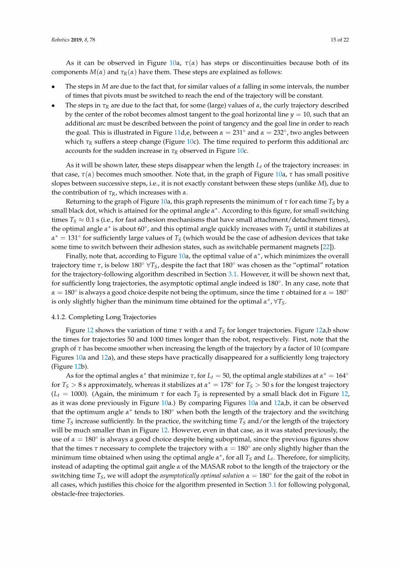
• The steps in τR are due to the fact that, for some (large) values of α, the curly trajectory describedby the center of the robot becomes almost tangent to the goal horizontal line y = 10, such that anadditional arc must be described between the point of tangency and the goal line in order to reachthe goal. This is illustrated in Figure 11d,e, between α = 231◦ and α = 232◦, two angles betweenwhich τR suffers a steep change (Figure 10c). The time required to perform this additional arcaccounts for the sudden increase in τR observed in Figure 10c.
As it will be shown later, these steps disappear when the length Lt of the trajectory increases: inthat case, τ(α) becomes much smoother. Note that, in the graph of Figure 10a, τ has small positiveslopes between successive steps, i.e., it is not exactly constant between these steps (unlike M), due tothe contribution of τR, which increases with α.
Returning to the graph of Figure 10a, this graph represents the minimum of τ for each time TS by asmall black dot, which is attained for the optimal angle α∗. According to this figure, for small switchingtimes TS ≈ 0.1 s (i.e., for fast adhesion mechanisms that have small attachment/detachment times),the optimal angle α∗ is about 60◦, and this optimal angle quickly increases with TS until it stabilizes atα∗ = 131◦ for sufficiently large values of TS (which would be the case of adhesion devices that takesome time to switch between their adhesion states, such as switchable permanent magnets [22]).
Finally, note that, according to Figure 10a, the optimal value of α∗, which minimizes the overalltrajectory time τ, is below 180◦ ∀TS, despite the fact that 180◦ was chosen as the “optimal” rotationfor the trajectory-following algorithm described in Section 3.1. However, it will be shown next that,for sufficiently long trajectories, the asymptotic optimal angle indeed is 180◦. In any case, note thatα = 180◦ is always a good choice despite not being the optimum, since the time τ obtained for α = 180◦
is only slightly higher than the minimum time obtained for the optimal α∗, ∀TS.
4.1.2. Completing Long Trajectories
Figure 12 shows the variation of time τ with α and TS for longer trajectories. Figure 12a,b showthe times for trajectories 50 and 1000 times longer than the robot, respectively. First, note that thegraph of τ has become smoother when increasing the length of the trajectory by a factor of 10 (compareFigures 10a and 12a), and these steps have practically disappeared for a sufficiently long trajectory(Figure 12b).
As for the optimal angles α∗ that minimize τ, for Lt = 50, the optimal angle stabilizes at α∗ = 164◦
for TS > 8 s approximately, whereas it stabilizes at α∗ = 178◦ for TS > 50 s for the longest trajectory(Lt = 1000). (Again, the minimum τ for each TS is represented by a small black dot in Figure 12,as it was done previously in Figure 10a.) By comparing Figures 10a and 12a,b, it can be observedthat the optimum angle α∗ tends to 180◦ when both the length of the trajectory and the switchingtime TS increase sufficiently. In the practice, the switching time TS and/or the length of the trajectorywill be much smaller than in Figure 12. However, even in that case, as it was stated previously, theuse of α = 180◦ is always a good choice despite being suboptimal, since the previous figures showthat the times τ necessary to complete the trajectory with α = 180◦ are only slightly higher than theminimum time obtained when using the optimal angle α∗, for all TS and Lt. Therefore, for simplicity,instead of adapting the optimal gait angle α of the MASAR robot to the length of the trajectory or theswitching time TS, we will adopt the asymptotically optimal solution α = 180◦ for the gait of the robot inall cases, which justifies this choice for the algorithm presented in Section 3.1 for following polygonal,obstacle-free trajectories.

Robotics 2019, 8, 78 16 of 22
𝛼 (º)
𝜏 (𝑠)
𝛼 = 180º𝛼∗ = 164º
𝑇 = 24 𝑠
𝑇 = 4 𝑠
𝑇 = 8 𝑠
𝑇 = 2 𝑠
𝑇 = 0.1 𝑠
𝛼 (º)
𝜏 (𝑠)
𝛼 = 180º
𝛼∗ = 178º
𝑇 = 100 𝑠
𝑇 = 4 𝑠
𝑇 = 50 𝑠
𝑇 = 2 𝑠
𝑇 = 0.1 𝑠
(a) (b)
Figure 12. Variation of time τ with α and TS, for (a) a trajectory Lt = 50 times longer than the robot,and (b) a trajectory Lt = 1000 times longer than the robot.
4.2. Experiment 2: Time Necessary to Traverse a Narrow Corridor
While the previous experiment dealt with the first stage of the trajectory-following algorithmproposed in Section 3 (i.e., tracking straight trajectories by using rotations of 180◦), this secondexperiment will analyze the second part of the aforementioned algorithm, which is focused ontraversing narrow corridors that constrain the motion of the robot and prevent it from performing suchwide 180◦ rotations. The problem analyzed here is illustrated in Figure 13a: we assume that the robotbegins initially with both pivots placed on one of the walls of the narrow corridor. Then, it begins toapply the gait described in Section 3.2, in which the robot places alternately one pivot on each wallor both pivots on the same wall, as illustrated in Figure 13a. In this experiment, we will analyze thetime spent by the robot to traverse the narrow corridor using this gait, assuming that the length of thecorridor is Lt times the length of the robot (see Figure 13a). The objective is that the center of the robottraverses a distance of Lt times its length, in the direction of the corridor.
𝜏 (𝑠)
𝜆
…
𝑇 = 24.1 𝑠
(b)(a)
Goal
Spa
ceto
be
trav
erse
dby
the
cent
er o
f th
ero
bot
1
2
𝐿·
𝐿
𝐿
𝜆 · 𝐿
Figure 13. (a) traversing a narrow corridor Lt times longer than the robot, with a width λ times thelength of the robot; (b) time to traverse a narrow corridor as a function of λ and TS (with Lt = 1).
In this case, unlike in the previous experiments, the angle rotated by the robot in each step isnot a variable parameter, but it is the angle between the walls of the corridor and the robot, when ithas one pivot on each wall. Instead, we will analyze next how the time τ necessary to traverse the

Robotics 2019, 8, 78 17 of 22
corridor depends on the ratio λ of the width of the corridor and the length of the robot. This ratioλ will be between 0 and 1. We exclude the case λ > 1 because, in that case, the robot can traversethe corridor using the gait illustrated previously in Figure 5c without colliding with the walls of thecorridor, a gait by which the robot rotates 180◦ about alternating pivots, without alternating the sign ofsuccessive rotations.
Figure 13b shows the variation of the time τ with λ and TS for a corridor whose length equals thatof the robot, i.e., Lt = 1. In this case, the overall time τ is computed similar to the previous experiment,i.e., τ accounts both for the time spent by the robot switching the adhesion state of its pivots, and thetime spent rotating about each pivot (assuming a unit angular speed ω = 1 rad/s), during the wholetrajectory until the center of the robot reaches the end of the corridor. As Figure 13b shows, the time τ
decreases when the width of the narrow corridor increases, attaining the minimum time when thiswidth equals the length of the robot (λ = 1), which is the limit case beyond which the robot would beable to traverse the corridor with the gait illustrated in Figure 5c, as stated earlier. In this experiment,the minimum time is always attained for λ = 1, independently of the switching time TS. In addition, inthis experiment, as in the previous one, the graph of τ versus λ presents some steps or discontinuities,which disappear when increasing the length Lt of the corridor to be traversed, obtaining smoothergraphs. However, unlike in the previous experiment, in this case, increasing the length of the trajectorydoes not affect the position of the minimum time τ, which is always attained for λ = 1.
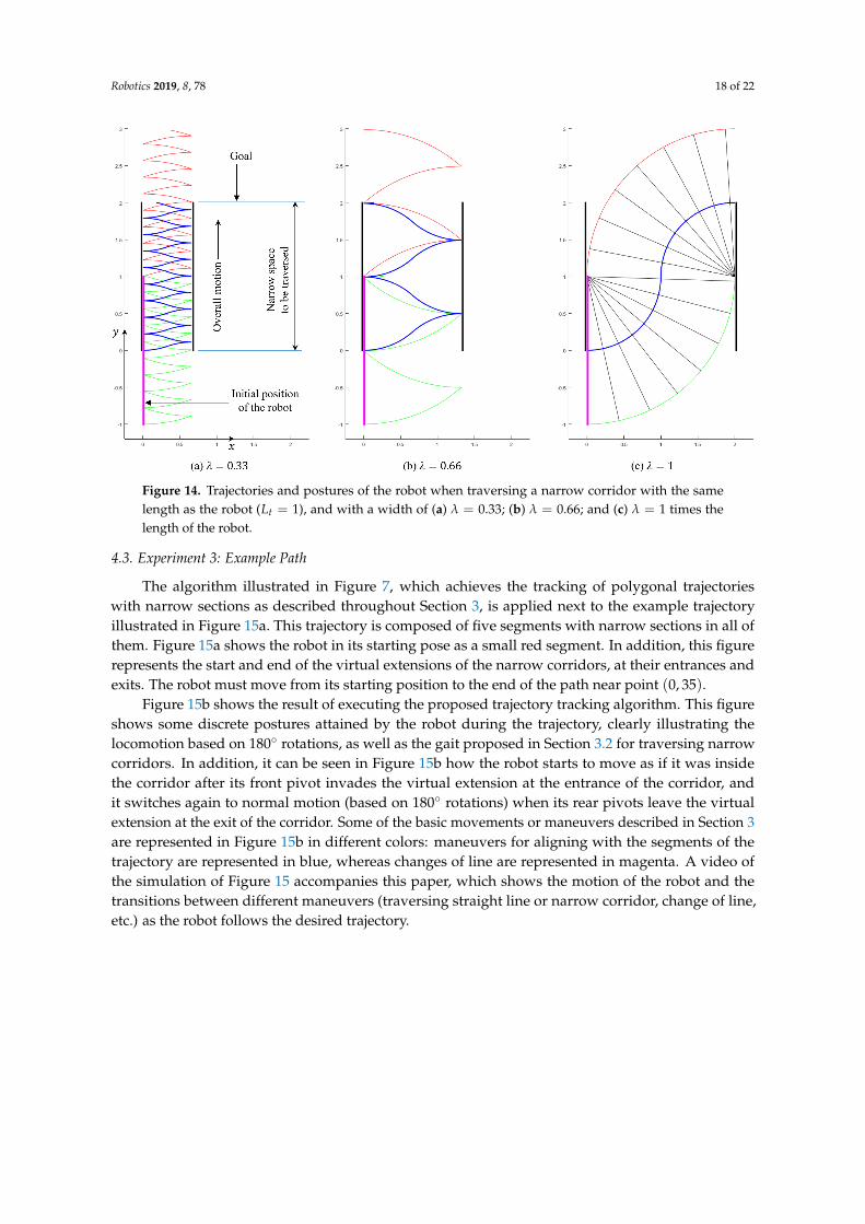
Finally, to further illustrate this experiment, Figure 14 shows the trajectory described by the centerof the robot (in blue) and the pivots (red and green) for traversing the narrow corridor, for differentvalues of λ (discrete postures of the robot along the motion are only shown for λ = 1, for clarityof representation). Note that the robot needs to perform many pivot changes for narrow corridors(Figure 14a), as well as many rotations, which justifies the higher values of τ observed in Figure 13b forsmall λ. In the limit of λ = 1 (Figure 14c), which is the fastest case according to Figure 13b, the robotonly needs to perform the following three steps: (1) rotate +90◦ about the upper pivot, (2) switch theadhesion state of the pivots, and (3) rotate −90◦ about the other pivot. The time required to performthese three steps would be [π/(2ω) + TS + π/(2ω) = π/ω + TS]. Since λ = 1, the width of thecorridor equals the length of the robot and the corridor can be traversed with a single rotation of 180◦
about the upper pivot, which would take a time equal to [π/ω], i.e., the time TS necessary to switchthe pivots is avoided. Thus, the fastest gait for traversing narrow corridors (a gait which occurs forcorridors nearly as wide as the length of the robot) always takes more time than the gait based onrotations of 180◦, which, in comparison, saves at least TS seconds for every Lt units of corridor thatneed to be traversed.
Robotics 2019, 8, 78 18 of 22
Figure 14. Trajectories and postures of the robot when traversing a narrow corridor with the samelength as the robot (Lt = 1), and with a width of (a) λ = 0.33; (b) λ = 0.66; and (c) λ = 1 times thelength of the robot.
4.3. Experiment 3: Example Path
The algorithm illustrated in Figure 7, which achieves the tracking of polygonal trajectorieswith narrow sections as described throughout Section 3, is applied next to the example trajectoryillustrated in Figure 15a. This trajectory is composed of five segments with narrow sections in all ofthem. Figure 15a shows the robot in its starting pose as a small red segment. In addition, this figurerepresents the start and end of the virtual extensions of the narrow corridors, at their entrances andexits. The robot must move from its starting position to the end of the path near point (0, 35).
Figure 15b shows the result of executing the proposed trajectory tracking algorithm. This figureshows some discrete postures attained by the robot during the trajectory, clearly illustrating thelocomotion based on 180◦ rotations, as well as the gait proposed in Section 3.2 for traversing narrowcorridors. In addition, it can be seen in Figure 15b how the robot starts to move as if it was insidethe corridor after its front pivot invades the virtual extension at the entrance of the corridor, andit switches again to normal motion (based on 180◦ rotations) when its rear pivots leave the virtualextension at the exit of the corridor. Some of the basic movements or maneuvers described in Section 3are represented in Figure 15b in different colors: maneuvers for aligning with the segments of thetrajectory are represented in blue, whereas changes of line are represented in magenta. A video ofthe simulation of Figure 15 accompanies this paper, which shows the motion of the robot and thetransitions between different maneuvers (traversing straight line or narrow corridor, change of line,etc.) as the robot follows the desired trajectory.

Robotics 2019, 8, 78 19 of 22
Initial pose (robot)
Narrow corridor
Goal
Virtual entrance
Virtual exit
(a) (b)
Figure 15. (a) Example of polygonal trajectory to be tracked, with some narrow sections. (b) Sequenceof poses described by the robot when tracking the trajectory.
5. Conclusions and Future Work
In this paper, we have described the MASAR robot: a new Modular And Single-Actuator Robot.This robot is a type-II SAMR since it has binary adhesion pads that can be adhered or detachedfrom the environment in order to produce the rotation of the robot about different axes, achievingin this way two- or three-dimensional motions using only one continuous actuator. In this paper,we have geometrically solved the planar trajectory tracking problem of this robot when followingpolygonal trajectories that may have narrow sections that constrain the amplitude of the rotations ofthe robot. The proposed gait consists in performing 180◦ rotations when there is no risk of collisionbetween the robot and obstacles of the environment, in order to maximize the distance traveled ina single step. We have shown that, for the MASAR robot, performing rotations of 180◦ minimizes thetime necessary for traversing long trajectories when the time required to switch the adhesion stateof the pivots is high. For shorter trajectories and/or pivots that switch their adhesion state quickly,a gait based on rotations of 180◦ may not be the optimal one, yet it is very close to it. When insidenarrow corridors, the proposed gait consists of rotating the robot until both pivots touch the walls ofthe corridor, since this also maximizes the distance traveled in a single step, subject to the narrownessof the corridor. The analysis of the proposed robot in narrow corridors, however, has shown that thisis not the optimal scenario for this robot, since its locomotion mode requires high times to traverseexcessively narrow corridors. This can be considered the worst-case scenario in which the proposedrobot would need to work, and for this reason it has been analyzed in this paper. Thus, the MASARrobot is most suitable to environments that allow wider rotations for the robot.
Regarding the trajectory-following problem analyzed in this paper, it was addressed froma purely geometric/kinematic perspective, and it assumed polygonal trajectories with narrow sections.In a practical implementation, we may have trajectories with other arbitrary shapes and obstacles,and a purely geometric approach may be insufficient when considering uncertainties of the map orlocation of the robot, as well as error in tracking of the trajectory (e.g., the robot may not be perfectlyaligned with the linear segments of the trajectory, such that the successive rotations of 180◦ wouldneed to be corrected slightly). In order to cope with all these factors, as part of ongoing and nearfuture work, we are currently approaching the trajectory-following problem of the MASAR robot froma closed-loop control perspective, departing from its velocity model and designing feedback controllers

Robotics 2019, 8, 78 20 of 22
that allow the tracking of arbitrary trajectories, in a similar way to the solutions proposed in [27] fora differential-drive two-wheeled mobile robot, optimizing time, distance, or energy consumption [28].Other ongoing and future tasks to address are: the analysis of trajectories that include concave planetransitions (Figure 4a), the analysis of the MASAR robot as a modular reconfigurable robot able toperform more complex motions by combining with identical modules (Figure 4b), and the constructionand validation of a prototype of the robot, including the adhesion pads that allow a single module towalk or combine with identical modules (Figure 3).
6. Patents
The MASAR robot was patented by the authors in Spain, with patent number ES2684377 andpriority date 31 March 2017.
Author Contributions: Conceptualization, A.P., J.M.M. and Ó.R.; methodology, A.P., J.G. and L.P.; software, A.P.,J.G. and L.P.; validation, A.P., J.G., and J.M.M.; formal analysis, L.P., J.M.M. and Ó.R.; investigation, A.P., J.G. andÓ.R.; resources, L.P., J.M.M. and Ó.R.; data curation, A.P., J.G. and J.M.M.; writing—original draft preparation, A.P.and J.G.; writing—review and editing, A.P., L.P. and Ó.R.; visualization, J.G., J.M.M. and A.P.; supervision, L.P.,J.M.M. and Ó.R.; project administration, L.P. and Ó.R.; funding acquisition, L.P. and Ó.R.
Funding: This research was funded by the Spanish Ministry of Science, Innovation and Universities throughGrant No. DPI2016-78361-R.
Conflicts of Interest: The authors declare no conflict of interest. The funders had no role in the design of thestudy; in the collection, analyses, or interpretation of data; in the writing of the manuscript, or in the decision topublish the results.
Abbreviations
The following abbreviations are used in this manuscript:
SAMR Single-Actuator Mobile RobotsMASAR Modular And Single-Actuator Robot
References
1. Zarrouk, D.; Fearing, R.S. Controlled in-plane locomotion of a hexapod using a single actuator. IEEE Trans.Robot. 2015, 31, 157–167. [CrossRef]
2. Soyguder, S.; Alli, H. Motion mechanism concept and morphology of a single actuator tetrapod walkingspider robot: The ROBOTURK SA-2 Robot. Ind. Robot Int. J. 2011, 38, 361–371. [CrossRef]
3. Choi, H.C.; Jung, G.P.; Cho, K.J. Design of a milli-scale, biomimetic platform for climbing on a roughsurface. In Proceedings of the 2015 IEEE International Conference on Robotics and Biomimetics (ROBIO),Zhuhai, China, 6–9 December 2015; pp. 2205–2210.
4. Birkmeyer, P.; Gillies, A.G.; Fearing, R.S. CLASH: Climbing vertical loose cloth. In Proceedings of the2011 IEEE/RSJ International Conference on Intelligent Robots and Systems, San Francisco, CA, USA, 25–30September 2011; pp. 5087–5093.
5. Degani, A.; Shapiro, A.; Choset, H.; Mason, M.T. A dynamic single actuator vertical climbing robot.In Proceedings of the 2007 IEEE/RSJ International Conference on Intelligent Robots and Systems, San Diego,CA, USA, 29 October–2 November 2007; pp. 2901–2906.
6. Zarrouk, D.; Mann, M.; Degani, N.; Yehuda, T.; Jarbi, N.; Hess, A. Single actuator wave-like robot (SAW):Design, modeling, and experiments. Bioinspir. Biomim. 2016, 11, 046004. [CrossRef] [PubMed]
7. Sfeir, J.; Shammas, E.; Asmar, D. Design and modeling of a novel single-actuator differentially driven robot.In Proceedings of the 2014 IEEE/ASME International Conference on Advanced Intelligent Mechatronics,Besançon, France, 8–11 July 2014; pp. 1079–1084.
8. Cheng, N.; Ishigami, G.; Hawthorne, S.; Chen, H.; Hansen, M.; Telleria, M.; Playter, R.; Iagnemma, K.Design and analysis of a soft mobile robot composed of multiple thermally activated joints driven by a singleactuator. In Proceedings of the 2010 IEEE International Conference on Robotics and Automation, Anchorage,AK, USA, 3–8 May 2010; pp. 5207–5212.

Robotics 2019, 8, 78 21 of 22
9. Telleria, M.J.; Hansen, M.; Campbell, D.; Servi, A.; Culpepper, M.L. Modeling and implementation ofsolder-activated joints for single-actuator, centimeter-scale robotic mechanisms. In Proceedings of the 2010 IEEEInternational Conference on Robotics and Automation, Anchorage, AK, USA, 3–8 May 2010; pp. 1681–1686.
10. Hoover, A.M.; Burden, S.; Fu, X.Y.; Sastry, S.S.; Fearing, R.S. Bio-inspired design and dynamicmaneuverability of a minimally actuated six-legged robot. In Proceedings of the 2010 3rd IEEE RAS & EMBSInternational Conference on Biomedical Robotics and Biomechatronics, Tokyo, Japan, 26–29 September 2010;pp. 869–876.
11. Birkmeyer, P.; Peterson, K.; Fearing, R.S. DASH: A dynamic 16g hexapedal robot. In Proceedings of the 2009IEEE/RSJ International Conference on Intelligent Robots and Systems, St. Louis, MO, USA, 10–15 October2009; pp. 2683–2689.
12. Refael, G.; Degani, A. Momentum-driven single-actuated swimming robot. In Proceedings of the 2015IEEE/RSJ International Conference on Intelligent Robots and Systems (IROS), Hamburg, Germany,28 September–2 October 2015; pp. 2285–2290.
13. Dharmawan, A.G.; Hariri, H.H.; Foong, S.; Soh, G.S.; Wood, K.L. Steerable miniature legged robot driven bya single piezoelectric bending unimorph actuator. In Proceedings of the 2017 IEEE International Conferenceon Robotics and Automation (ICRA), Singapore, 29 May–3 June 2017; pp. 6008–6013.
14. Tang, C.; Li, B.; Chen, H. U-turning an agile robotic cube by a soft dielectric elastomer resonator. In Proceedingsof the 2018 IEEE International Conference on Soft Robotics (RoboSoft), Livorno, Italy, 24–28 April 2018;pp. 333–338.
15. Zuliani, F.; Liu, C.; Paik, J.; Felton, S.M. Minimally Actuated Transformation of Origami Machines.IEEE Robot. Autom. Lett. 2018, 3, 1426–1433. [CrossRef]
16. Toyoizumi, T.; Yonekura, S.; Kamimura, A.; Tadakuma, R.; Kawaguchi, Y. 1DOF spherical mobile robot thatcan generate two motions. In Proceedings of the 2010 IEEE/RSJ International Conference on IntelligentRobots and Systems, Taipei, Taiwan, 18–22 October 2010; pp. 2884–2889.
17. Ribas, L.; Mujal, J.; Izquierdo, M.; Ramon, E. Motion control for a single-motor robot with an undulatorylocomotion system. In Proceedings of the 2007 Mediterranean Conference on Control Automation, Athens,Greece, 27–29 June 2007; pp. 1–6.
18. Ho, T.; Lee, S. A novel design of a robot that can jump and roll with a single actuator. In Proceedings of the2012 IEEE/RSJ International Conference on Intelligent Robots and Systems, Vilamoura, Algarve, Portugal,7–12 October 2012; pp. 908–913.
19. Burdick, J.; Fiorini, P. Minimalist Jumping Robots for Celestial Exploration. Int. J. Robot. Res. 2003, 22,653–674. [CrossRef]
20. Zhao, J.; Xu, J.; Gao, B.; Xi, N.; Cintron, F.J.; Mutka, M.W.; Xiao, L. MSU jumper: A single-motor-actuatedminiature steerable jumping robot. IEEE Trans. Robot. 2013, 29, 602–614. [CrossRef]
21. Schmidt, D.; Berns, K. Climbing robots for maintenance and inspections of vertical structures. A survey ofdesign aspects and technologies. Robot. Auton. Syst. 2013, 61, 1288–1305. [CrossRef]
22. Peidró, A.; Tavakoli, M.; Marín, J.M.; Reinoso, Ó. Design of compact switchable magnetic grippers for theHyReCRo structure-climbing robot. Mechatronics 2019, 59, 199–212. [CrossRef]
23. Tavakoli, M.; Viegas, C.; Romão, J.C.; Neto, P.; de Almeida, A.T. Switchable magnets for robotics applications.In Proceedings of the 2015 IEEE/RSJ International Conference on Intelligent Robots and Systems (IROS),Hamburg, Germany, 28 September–2 October 2015; pp. 4325–4330.
24. Kim, H.; Kim, D.; Yang, H.; Lee, K.; Seo, K.; Chang, D.; Kim, J. Development of a wall-climbing robot using atracked wheel mechanism. J. Mech. Sci. Technol. 2008, 22, 1490–1498. [CrossRef]
25. Mir-Nasiri, N.; Siswoyo, H.; Ali, M.H. Portable autonomous window cleaning robot. Procedia Comput. Sci.2018, 133, 197–204. [CrossRef]
26. Moubarak, P.; Ben-Tzvi, P. Modular and reconfigurable mobile robotics. Robot. Auton. Syst. 2012, 60, 1648–1663.[CrossRef]

Robotics 2019, 8, 78 22 of 22
27. Koh, K.C.; Cho, H.S. A Smooth Path Tracking Algorithm for Wheeled Mobile Robots with DynamicConstraints. J. Intell. Robot. Syst. 1999, 24, 367–385. [CrossRef]
28. Fabbrini, A.; Garulli, A.; Mercorelli, P. A Trajectory Generation Algorithm for Optimal Consumption inElectromagnetic Actuators. IEEE Trans. Control Syst. Technol. 2012, 20, 1025–1032. [CrossRef]
c© 2019 by the authors. Licensee MDPI, Basel, Switzerland. This article is an open accessarticle distributed under the terms and conditions of the Creative Commons Attribution(CC BY) license (http://creativecommons.org/licenses/by/4.0/).