tŪranga library christchurch – hybrid rocking …
TRANSCRIPT
TŪRANGA LIBRARY CHRISTCHURCH – HYBRID ROCKING PRECAST CONCRETE WALL PANELS
TIM SHANNON, TECHNICAL DIRECTOR / DR JAMALEDIN BORZOUIE, PROJECT
ENGINEER / HELEN TRAPPITT, DIRECTOR
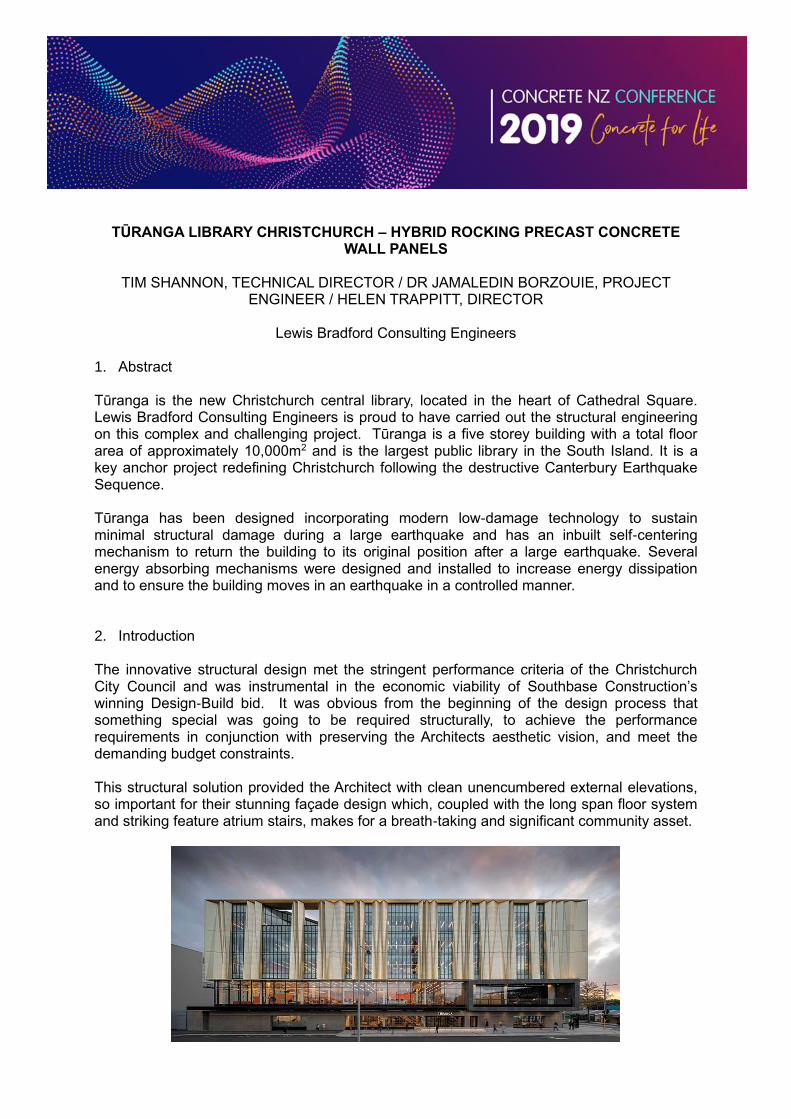
Lewis Bradford Consulting Engineers 1. Abstract Tūranga is the new Christchurch central library, located in the heart of Cathedral Square. Lewis Bradford Consulting Engineers is proud to have carried out the structural engineering on this complex and challenging project. Tūranga is a five storey building with a total floor area of approximately 10,000m2 and is the largest public library in the South Island. It is a key anchor project redefining Christchurch following the destructive Canterbury Earthquake Sequence. Tūranga has been designed incorporating modern low-damage technology to sustain minimal structural damage during a large earthquake and has an inbuilt self-centering mechanism to return the building to its original position after a large earthquake. Several energy absorbing mechanisms were designed and installed to increase energy dissipation and to ensure the building moves in an earthquake in a controlled manner. 2. Introduction The innovative structural design met the stringent performance criteria of the Christchurch City Council and was instrumental in the economic viability of Southbase Construction’s winning Design-Build bid. It was obvious from the beginning of the design process that something special was going to be required structurally, to achieve the performance requirements in conjunction with preserving the Architects aesthetic vision, and meet the demanding budget constraints. This structural solution provided the Architect with clean unencumbered external elevations, so important for their stunning façade design which, coupled with the long span floor system and striking feature atrium stairs, makes for a breath-taking and significant community asset.
3. Structural Overview
A key feature of the structural design of Tūranga was the incorporation of a dual seismic
resisting system primarily consisting of an integrated, self-centering mechanism in the form
of hybrid concrete shear walls that can rock to isolate the building from peak earthquake
accelerations.
Each wall has high tensile, unbonded, post-tensioned steel cables that clamp the wall to the
foundations with approximately 10,000 kN of force per wall. When the walls rock the stretch
of these cables further increases the restoring force and returns the building to its original
position after an earthquake. Thanks to the post-tensioning, seismic energy absorbing
devices (called high force to volume lead dampers or HF2V dampers) attached to the wall
bases and steel U-shaped flexural plates (UFPs) at each end of the walls; the rocking motion
occurs in a controlled manner.
The second component of the seismic resisting system is the steel moment resisting frame
around the full building perimeter with rocking connections at the base. These frames further
enhance the building performance, and provide the added assurance of a building with two
independent seismic resisting systems acting together.
The combination of the dual system, replaceable energy absorbing devices and the self-
centering mechanism of the building provides a seismically resilient structure – delivering the
performance level required and the property protection that the city deserves.
4. Building Structural Design
4.1 Structural Performance Brief
An especially high level of structural resilience was demanded for Tūranga by the
challenging tender performance specification which required:
• Negligible structural damage to the main structure for seismic events with a return
period of up to 250 years.
• The main structure is required to be repairable and the residual drift is limited to
0.15% for Ultimate Limit State (ULS) seismic events with a 1000-year return period.
This included the effects of foundation settlement.
• Life safety preserved for Maximum Credible Earthquake (MCE) with a 2500-year
return period.
• Structure must be compatible with an exacting Architectural layout.
Originally seven contractors, paired with their consulting engineers registered an interest in
tendering the project. Three preferred tenderers were selected and proceeded to concept
design, with an eight week timeframe to refine a specimen design (the incumbent structural
design).
The incumbent structural design included steel moment resisting frames with diagonal
viscous damped braces and a composite steel deck floor system. The foundation system
consisted of a basement structure with deep piles, founded approximately 20-30m below
ground level.
During the tight eight week design-build tender period, Lewis Bradford developed an
alternative structural solution. The incumbent design was replaced by concrete hybrid
rocking walls located in the central cores with supplementary steel moment resisting frames
located around the perimeter. Removal of diagonal cross bracing (or solid wall elements)
from the perimeter of the building had significant architectural merit by enhancing aesthetics,
increasing net lettable areas, and providing greater long term flexibility of the internal built
space. The concrete cores also provided significant benefit providing a robust fire rated
egress path.
In addition, in collaboration with Southbase Construction, Tonkin and Taylor geotechnical
engineers, and the services engineers Powell Fenwick, an early decision was proposed by
Lewis Bradford to remove the planned basement from the building and relocate the entire
plantroom to roof level.
Whilst it is acknowledged that this was challenging for our building services colleagues, it
provided significant cost savings and meant the building could be founded with shallow
foundations on a robust near surface gravel layer – this mitigated the complications, risks
and expense associated with deep piles in Christchurch.
4.2 Gravity Load Resisting Elements
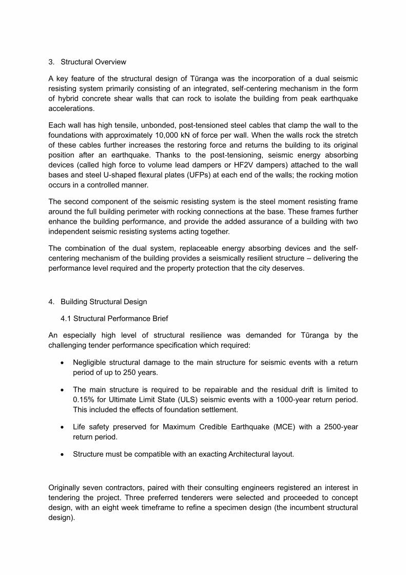
The gravity frame consists of a structural steel superstructure, comprising concrete filled tubular composite columns and welded steel beams that typically span west to east. The suspended floor system consists of 325mm deep (bespoke) prestressed precast ribs with timber infills and a 90mm insitu topping slab. The floor system provides a (generally) unobstructed services plenum between the floor ribs and ceiling. The floor system spans up to 12.4m, generally north-south across the building (the short direction of the building). The bespoke 325mm deep prestressed ribs are supported on the bottom flanges of the
internal gravity welded beams (typically 455WB’s), refer figure 1. The ribs were increased in
depth more than typical floor ribs for a span 12.4m to allow a single row of propping during
construction, rather than 2-3 rows typically used for this span. The rib depth also optimised
the footfall vibration response of the long span floors to within reasonable limits.
Figure 1:Typical precast floor rib seating detail
A light weight steel portal frame structure at roof level encapsulates the roof level plant room. Foundations consist of a grillage of concrete foundation beams bearing on an intermediate gravel layer.
4.3 Lateral Load Resisting Elements
4.3.1 Hybrid Walls (Column – Wall – Column System)
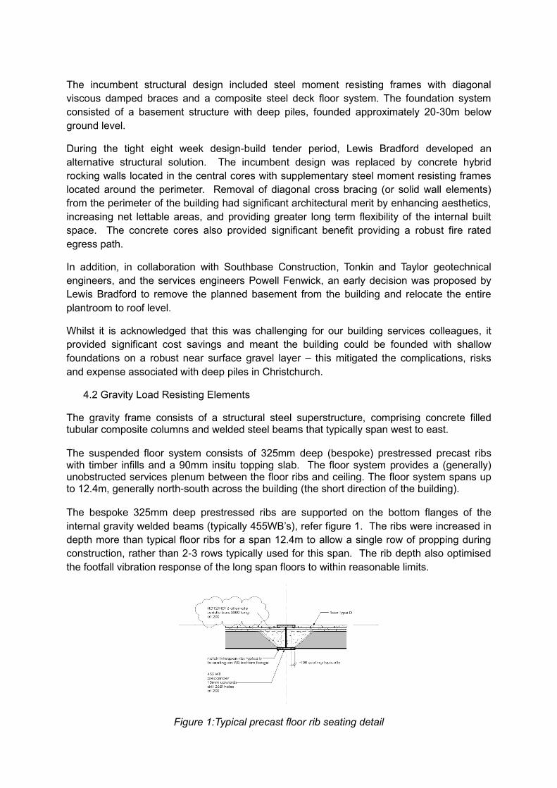
The Hybrid walls are arranged into three main cores and provide approximately 75% of the
total seismic resistance for the building, with the remaining 25% provided by the perimeter
steel frames. It was recognised early in the design-build process that the existing stair and
lift cores were well positioned for a shear wall solution. A shear wall solution was considered
particularly beneficial due to the double height storey at 2nd floor (soft storey). The walls are
located such that the centre of strength, damping and stiffness all closely correlate to the
centre of mass with negligible adjustments to the original Architectural design, as required by
the design brief.
Figure 2: Hybrid walls and perimeter steel moment resisting frames
On the corner of each core arrangement, a vertical column provides support for gravity floor
beams and also provides the connection points for seismic dissipators called U-Shaped
Flexural Plates (UFP’s) (Kelly et al, 1972). This column-wall-column arrangement is a
relatively novel approach to a rocking wall system, however it allows the high performance
aspects of the self-centring hybrid wall system to be integrated into the stair cores. Utilising
the cores is also ideal from an Architectural and Building Services perspective.
The term ‘hybrid’ reflects that each rocking wall has a combination of hysteretic damping
from the UFP’s located at wall ends, de-bonded starters centrally at the base joints of the
walls, and a total system re-centring force provided by centrally located high strength un-
EAST CORE
CENTRAL CORE
WEST CORE
STEEL MOMENT RESISTING FRAME (FULL PERIMETER)
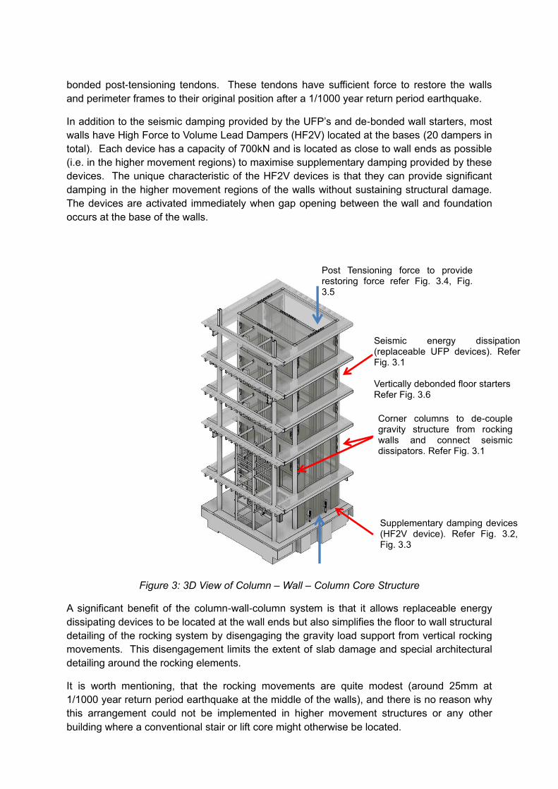
bonded post-tensioning tendons. These tendons have sufficient force to restore the walls
and perimeter frames to their original position after a 1/1000 year return period earthquake.
In addition to the seismic damping provided by the UFP’s and de-bonded wall starters, most
walls have High Force to Volume Lead Dampers (HF2V) located at the bases (20 dampers in
total). Each device has a capacity of 700kN and is located as close to wall ends as possible
(i.e. in the higher movement regions) to maximise supplementary damping provided by these
devices. The unique characteristic of the HF2V devices is that they can provide significant
damping in the higher movement regions of the walls without sustaining structural damage.
The devices are activated immediately when gap opening between the wall and foundation
occurs at the base of the walls.
Figure 3: 3D View of Column – Wall – Column Core Structure
A significant benefit of the column-wall-column system is that it allows replaceable energy
dissipating devices to be located at the wall ends but also simplifies the floor to wall structural
detailing of the rocking system by disengaging the gravity load support from vertical rocking
movements. This disengagement limits the extent of slab damage and special architectural
detailing around the rocking elements.
It is worth mentioning, that the rocking movements are quite modest (around 25mm at
1/1000 year return period earthquake at the middle of the walls), and there is no reason why
this arrangement could not be implemented in higher movement structures or any other
building where a conventional stair or lift core might otherwise be located.
Supplementary damping devices (HF2V device). Refer Fig. 3.2, Fig. 3.3
Post Tensioning force to provide restoring force refer Fig. 3.4, Fig. 3.5
Seismic energy dissipation (replaceable UFP devices). Refer Fig. 3.1 Vertically debonded floor starters Refer Fig. 3.6
Corner columns to de-couple gravity structure from rocking walls and connect seismic dissipators. Refer Fig. 3.1
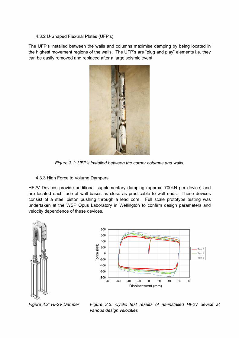
4.3.2 U-Shaped Flexural Plates (UFP’s)
The UFP’s installed between the walls and columns maximise damping by being located in
the highest movement regions of the walls. The UFP’s are “plug and play” elements i.e. they
can be easily removed and replaced after a large seismic event.
Figure 3.1: UFP’s installed between the corner columns and walls.
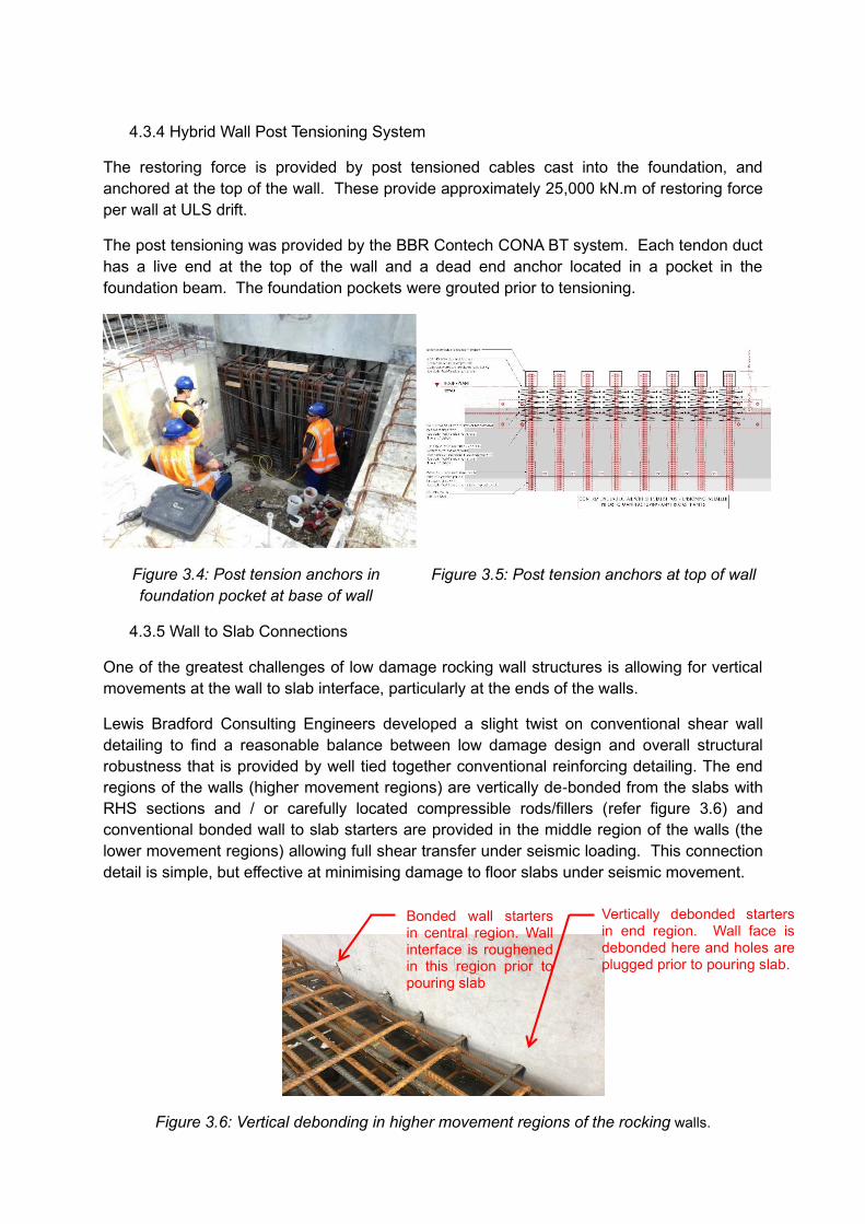
4.3.3 High Force to Volume Dampers
HF2V Devices provide additional supplementary damping (approx. 700kN per device) and
are located each face of wall bases as close as practicable to wall ends. These devices
consist of a steel piston pushing through a lead core. Full scale prototype testing was
undertaken at the WSP Opus Laboratory in Wellington to confirm design parameters and
velocity dependence of these devices.
Figure 3.2: HF2V Damper Figure 3.3: Cyclic test results of as-installed HF2V device at
various design velocities
4.3.4 Hybrid Wall Post Tensioning System
The restoring force is provided by post tensioned cables cast into the foundation, and
anchored at the top of the wall. These provide approximately 25,000 kN.m of restoring force
per wall at ULS drift.
The post tensioning was provided by the BBR Contech CONA BT system. Each tendon duct
has a live end at the top of the wall and a dead end anchor located in a pocket in the
foundation beam. The foundation pockets were grouted prior to tensioning.
Figure 3.4: Post tension anchors in
foundation pocket at base of wall
Figure 3.5: Post tension anchors at top of wall
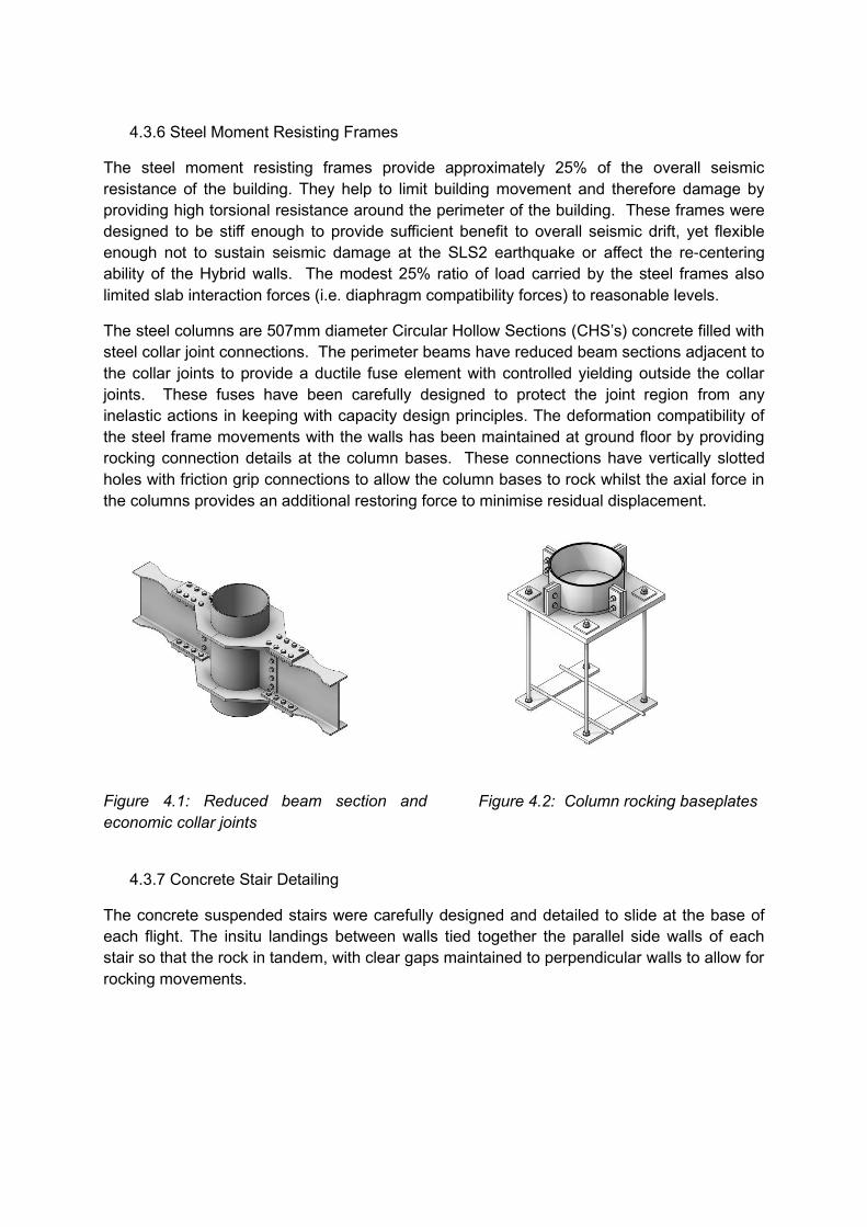
4.3.5 Wall to Slab Connections
One of the greatest challenges of low damage rocking wall structures is allowing for vertical
movements at the wall to slab interface, particularly at the ends of the walls.
Lewis Bradford Consulting Engineers developed a slight twist on conventional shear wall
detailing to find a reasonable balance between low damage design and overall structural
robustness that is provided by well tied together conventional reinforcing detailing. The end
regions of the walls (higher movement regions) are vertically de-bonded from the slabs with
RHS sections and / or carefully located compressible rods/fillers (refer figure 3.6) and
conventional bonded wall to slab starters are provided in the middle region of the walls (the
lower movement regions) allowing full shear transfer under seismic loading. This connection
detail is simple, but effective at minimising damage to floor slabs under seismic movement.
Figure 3.6: Vertical debonding in higher movement regions of the rocking walls.
Bonded wall starters in central region. Wall interface is roughened in this region prior to pouring slab
Vertically debonded starters in end region. Wall face is debonded here and holes are plugged prior to pouring slab.
4.3.6 Steel Moment Resisting Frames
The steel moment resisting frames provide approximately 25% of the overall seismic
resistance of the building. They help to limit building movement and therefore damage by
providing high torsional resistance around the perimeter of the building. These frames were
designed to be stiff enough to provide sufficient benefit to overall seismic drift, yet flexible
enough not to sustain seismic damage at the SLS2 earthquake or affect the re-centering
ability of the Hybrid walls. The modest 25% ratio of load carried by the steel frames also
limited slab interaction forces (i.e. diaphragm compatibility forces) to reasonable levels.
The steel columns are 507mm diameter Circular Hollow Sections (CHS’s) concrete filled with
steel collar joint connections. The perimeter beams have reduced beam sections adjacent to
the collar joints to provide a ductile fuse element with controlled yielding outside the collar
joints. These fuses have been carefully designed to protect the joint region from any
inelastic actions in keeping with capacity design principles. The deformation compatibility of
the steel frame movements with the walls has been maintained at ground floor by providing
rocking connection details at the column bases. These connections have vertically slotted
holes with friction grip connections to allow the column bases to rock whilst the axial force in
the columns provides an additional restoring force to minimise residual displacement.
Figure 4.1: Reduced beam section and
economic collar joints
Figure 4.2: Column rocking baseplates
4.3.7 Concrete Stair Detailing
The concrete suspended stairs were carefully designed and detailed to slide at the base of
each flight. The insitu landings between walls tied together the parallel side walls of each
stair so that the rock in tandem, with clear gaps maintained to perpendicular walls to allow for
rocking movements.
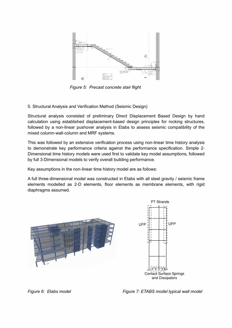
Figure 5: Precast concrete stair flight
5. Structural Analysis and Verification Method (Seismic Design)
Structural analysis consisted of preliminary Direct Displacement Based Design by hand
calculation using established displacement-based design principles for rocking structures,
followed by a non-linear pushover analysis in Etabs to assess seismic compatibility of the
mixed column-wall-column and MRF systems.
This was followed by an extensive verification process using non-linear time history analysis
to demonstrate key performance criteria against the performance specification. Simple 2-
Dimensional time history models were used first to validate key model assumptions, followed
by full 3-Dimensional models to verify overall building performance.
Key assumptions in the non-linear time history model are as follows:
A full three-dimensional model was constructed in Etabs with all steel gravity / seismic frame
elements modelled as 2-D elements, floor elements as membrane elements, with rigid
diaphragms assumed.
Figure 6: Etabs model Figure 7: ETABS model typical wall model
The shear walls were modelled by assigning the wall section as a 2-D frame element.
Nonlinear links were defined to model the UFP, debonded mild steel fuses, post tensioned
strands, HF2V dampers, and the contact surface between the rocking wall and the
foundation as illustrated above.
• Baird et al. (2014) recommends using the Ramberg-Osgood function to model the
UFP hysteretic curve. However, this function was not available in ETABS and
multilinear plastic links with Kinematic type hysteresis have been used for modelling
of the UFPs to approximate this function with a best fit bi-linear function.
• HF2V devices were modelled based on parameters provided by Professor Geoff
Rodgers from University of Canterbury then verified by full scale testing.
• The concrete surface was modelled with multilinear elastic links with some
modification to the Mander et al. (1988) confined model to match the neutral axis with
the monolithic beam analogy as defined by Pampanin (2009).
Professor Brendon Bradley provided seven suitable scaled earthquake records for each of
the SLS2 (1/250 year), ULS (1/1000 year) and MCE (1/2500 year) earthquake return periods.
These were utilised in the time history analysis to confirm the following performance points:
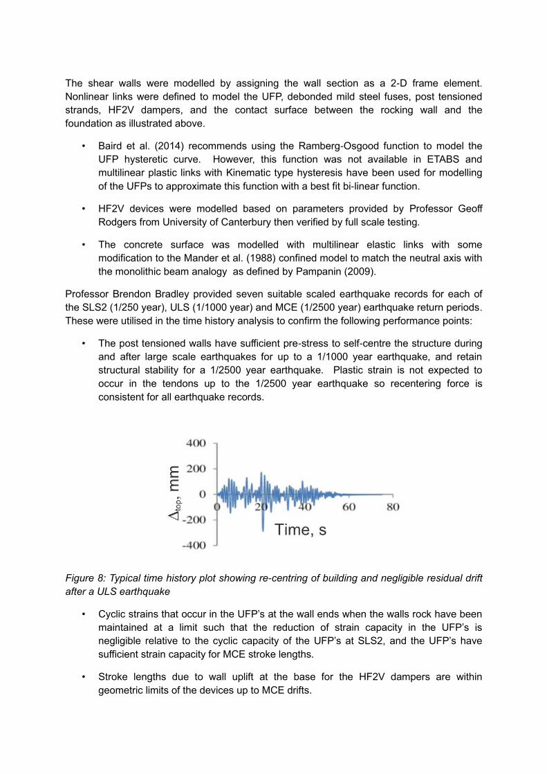
• The post tensioned walls have sufficient pre-stress to self-centre the structure during
and after large scale earthquakes for up to a 1/1000 year earthquake, and retain
structural stability for a 1/2500 year earthquake. Plastic strain is not expected to
occur in the tendons up to the 1/2500 year earthquake so recentering force is
consistent for all earthquake records.
Figure 8: Typical time history plot showing re-centring of building and negligible residual drift
after a ULS earthquake
• Cyclic strains that occur in the UFP’s at the wall ends when the walls rock have been
maintained at a limit such that the reduction of strain capacity in the UFP’s is
negligible relative to the cyclic capacity of the UFP’s at SLS2, and the UFP’s have
sufficient strain capacity for MCE stroke lengths.
• Stroke lengths due to wall uplift at the base for the HF2V dampers are within
geometric limits of the devices up to MCE drifts.
• Seismic drift is approximately 1.5% to 1.6% at 1/1000 year earthquake. This is at the
extreme points of the building, movements are less around the core areas of the
building where there is greatest intensification of services and Architectural elements.
• The walls do not slide at the base. (The walls were cast into shear key pockets for
additional redundancy).
• Wall / Slab vertical movements were within expected limits calculated used hand
calculations. Expected crack widths based on vertical movements of the walls show
negligible structural impact at SLS2, and repairable damage at ULS. It is anticipated
when the wall re-centres cracks would largely close.
• The building will be readily repairable after a 1/1000 year earthquake by analysis.
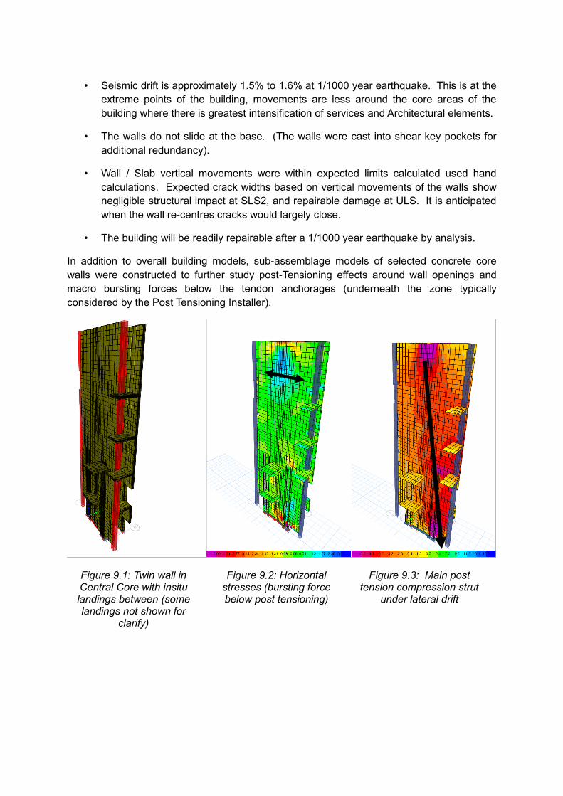
In addition to overall building models, sub-assemblage models of selected concrete core
walls were constructed to further study post-Tensioning effects around wall openings and
macro bursting forces below the tendon anchorages (underneath the zone typically
considered by the Post Tensioning Installer).
Figure 9.1: Twin wall in Central Core with insitu landings between (some landings not shown for
clarify)
Figure 9.2: Horizontal stresses (bursting force below post tensioning)
Figure 9.3: Main post tension compression strut
under lateral drift
6. Construction
6.1 Concrete Tilt Panels
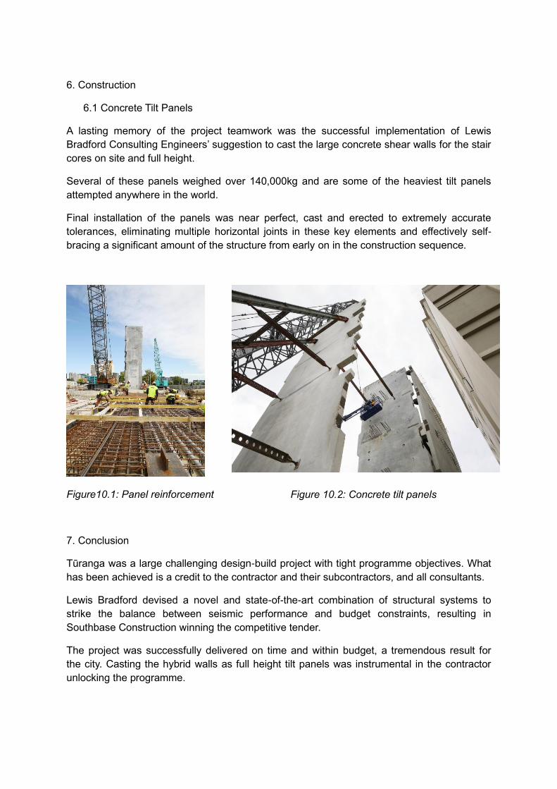
A lasting memory of the project teamwork was the successful implementation of Lewis
Bradford Consulting Engineers’ suggestion to cast the large concrete shear walls for the stair
cores on site and full height.
Several of these panels weighed over 140,000kg and are some of the heaviest tilt panels
attempted anywhere in the world.
Final installation of the panels was near perfect, cast and erected to extremely accurate
tolerances, eliminating multiple horizontal joints in these key elements and effectively self-
bracing a significant amount of the structure from early on in the construction sequence.
Figure10.1: Panel reinforcement Figure 10.2: Concrete tilt panels
7. Conclusion
Tūranga was a large challenging design-build project with tight programme objectives. What
has been achieved is a credit to the contractor and their subcontractors, and all consultants.
Lewis Bradford devised a novel and state-of-the-art combination of structural systems to
strike the balance between seismic performance and budget constraints, resulting in
Southbase Construction winning the competitive tender.
The project was successfully delivered on time and within budget, a tremendous result for
the city. Casting the hybrid walls as full height tilt panels was instrumental in the contractor
unlocking the programme.
8. Acknowledgements
Lewis Bradford acknowledges the specialist input of Professor Brendon Bradley for providing
the seven scaled ground motion records for the Time History Analysis embodying the latest
seismic hazard research undertaken at University of Canterbury, and the valuable roles of
the peer reviewers for the Central Library project: Ruamoko Solutions and Professor Stefano
Pampanin at each stage of the design process. By collaborating with key personnel from the
University of Canterbury, Lewis Bradford were able to base our analysis on the most recent
evidence available from experimental and numerical testing.
9. References
• Baird, A., Smith, T., Palermo, A. and Pampanin, S., 2014. Experimental and numerical study of U-shape flexural plate (UFP) dissipators. In New Zealand Society for Earthquake Engineering Conference, Christchurch, New Zealand.
• Kelly, J.M., Skinner, R.I. and Heine, A.J., 1972. Mechanisms of energy absorption in special devices for use in earthquake resistant structures. Bulletin of NZ Society for Earthquake Engineering, 5(3), pp.63-88.
• Mander, J.B., Priestley, M.J. and Park, R., 1988. Theoretical stress-strain model for confined concrete. Journal of structural engineering, 114(8), pp.1804-1826.
• Pampanin, S., and Marriott, D. 2010. NZCS PRESSS Design Handbook. New Zealand Concrete Society, Wellington, New Zealand.