tranquility vertical stack (tsm) series · tsm units’ consist of 2 major components - cabinet...
TRANSCRIPT
ClimateMaster works continually to improve its products. As a result, the design and specifi cations of each product at the time of order may be changed without notice and may not be as described herein. Please contact ClimateMaster's Customer Service Department at 1-405-745-6000 for specifi c information on the current design and specifi cations. Statements and other information contained herein are not express warranties and do not form the basis of any bargain between the parties, but are merely ClimateMaster's opinion or commendation of its products. The latest version of this document is available at climatemaster.com.
*LC994* LC994 Rev.: September 26, 2018
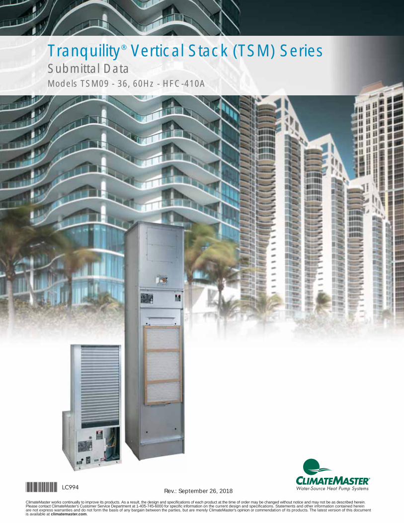
Tranquility® Vertical Stack (TSM) Series Submittal DataModels TSM09 - 36, 60Hz - HFC-410A
ClimateMaster works continually to improve its products. As a result, the design and specifi cations of each product at the time of order may be changed without notice and may not be as described herein. Please contact ClimateMaster's Customer Service Department at 1-405-745-6000 for specifi c information on the current design and specifi cations. Statements and other information contained herein are not express warranties and do not form the basis of any bargain between the parties, but are merely ClimateMaster's opinion or commendation of its products. The latest version of this document is available at climatemaster.com.
Page ______ of ______LC994 - 2
Unit Features 4iGate® Communicating Controls 6
vFlow® Modulating Valve 7
Selection Procedure 8TSM Series Nomenclature 10
TSM Series Accessory Nomenclature 11Performance Data – AHRI/ASHRAE/ISO 13256-1 14
Performance Data – Selection Notes 15Performance Data – TSM09 with PSC Motor 16Performance Data – TSM12 with PSC Motor 17Performance Data – TSM15 with PSC Motor 18Performance Data – TSM18 with PSC Motor 19Performance Data – TSM24 with PSC Motor 20Performance Data – TSM30 with PSC Motor 21Performance Data – TSM36 with PSC Motor 22
Performance Data – TSM09 with ECM Motor 23Performance Data – TSM12 with ECM Motor 24Performance Data – TSM15 with ECM Motor 25Performance Data – TSM18 with ECM Motor 26Performance Data – TSM24 with ECM Motor 27Performance Data – TSM30 with ECM Motor 28Performance Data – TSM36 with ECM Motor 29
Performance Data Correction Tables and Water Pressure Drop Adders 30Blower Performance Data – TSM09 (PSC/ ECM-CT/ECM-CV) 32Blower Performance Data – TSM12 (PSC/ ECM-CT/ECM-CV) 33Blower Performance Data – TSM15 (PSC/ ECM-CT/ECM-CV) 34Blower Performance Data – TSM18 (PSC/ ECM-CT/ECM-CV) 35Blower Performance Data – TSM24 (PSC/ ECM-CT/ECM-CV) 36Blower Performance Data – TSM30 (PSC/ ECM-CT/ECM-CV) 37Blower Performance Data – TSM36 (PSC/ ECM-CT/ECM-CV) 38
ECM Blower Performance Data 39Physical Data 40
Table of Contents
TSM Vertical Stack
ClimateMaster works continually to improve its products. As a result, the design and specifi cations of each product at the time of order may be changed without notice and may not be as described herein. Please contact ClimateMaster's Customer Service Department at 1-405-745-6000 for specifi c information on the current design and specifi cations. Statements and other information contained herein are not express warranties and do not form the basis of any bargain between the parties, but are merely ClimateMaster's opinion or commendation of its products. The latest version of this document is available at climatemaster.com.
Page ______ of ______LC994 - 3
Electrica Data - Low Static PSC Motor (208/230V) and (265V) 41Electrical Data - ECM-CV Motor (208/230V) and (265V) 42Electrical Data - ECM-CT Motor (208/230V) and (265V) 43
Typical Unit - Exploded View 44TSM – Standard Unit, Furred In Cabinet with Risers 45
TSM – Master Unit, Furred In Cabinet 46TSM – Slave Unit, Furred In Cabinet, No Risers 47
Master/Slave Cabinet Installation 48Cabinet Dimensions 49
Cabinet Slot Dimensions and Riser Arrangements 50TSM Cabinet Confi gurations 51
Typical Cabinet w/"G" Panel Installation 52Typical Recessed Cabinet w/"G" Panel and Frame Installation 53
Hinged “G” Style Return Air Panel – AVHSG Series 54“L” Style (Flush Mounted) Return Air Panel – AVHRL Series 55
Hose Kits and Stands 56Supply Air Openings and Grilles 57
Thermostats 59TSM Cabinet Options 60
ECM Blower Motor (Optional) 61Riser Defi nitions 62
Riser GPM Defi nitions and Sizing 63Riser Diameter Sizing 64
Swage Riser Length Defi nitions and Sizing 65Swage Riser Extension Defi nitions and Sizing 66
Setting Cabinet 67Slab Slot Chart - 3 Pipe 68
Shipping 69Engineering Specifi cations 70
Performance Sheet 81Revision History 82
Table of Contents
TSM Vertical Stack
ClimateMaster works continually to improve its products. As a result, the design and specifi cations of each product at the time of order may be changed without notice and may not be as described herein. Please contact ClimateMaster's Customer Service Department at 1-405-745-6000 for specifi c information on the current design and specifi cations. Statements and other information contained herein are not express warranties and do not form the basis of any bargain between the parties, but are merely ClimateMaster's opinion or commendation of its products. The latest version of this document is available at climatemaster.com.
Page ______ of ______LC994 - 4
TRANQUILITY® VERTICAL STACK (TSM) SERIES WITH EARTHPURE® REFRIGERANT
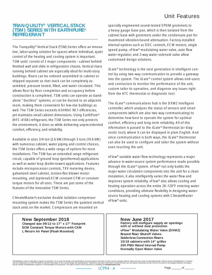
The Tranquility® Vertical Stack (TSM) Series offers an innova-tive, labor-saving solution for spaces where individual, quiet control of the heating and cooling system is important. TSM units’ consist of 2 major components - cabinet behind fi nished wall and slide in refrigeration chassis. Vertical risers running behind cabinet are especially ideal for multi-story buildings. Risers can be ordered assembled to cabinet or shipped separate so riser stack can be completely as-sembled, pressure tested, fi lled, and water circulated. This allows fl oor by fl oor completion and occupancy before construction is completed. TSM units can operate as stand-alone “ductless” systems, or can be ducted to an adjacent room, making them convenient for low-rise buildings as well. The TSM Series exceeds ASHRAE 90.1 effi ciencies, yet maintains small cabinet dimensions. Using EarthPure® (HFC-410A) refrigerant, the TSM Series not only protects the environment, it does so while delivering unprecedented comfort, effi ciency, and reliability.
Available in sizes 3/4 ton (2.6 kW) through 3 tons (10.6 kW) with numerous cabinet, water piping and control choices, the TSM Series offers a wide range of options for most installations. The TSM has an extended range refrigerant circuit, capable of ground loop (geothermal) applications as well as water loop (boiler-tower) applications. Features include microprocessor controls, TXV metering device, galvanized steel cabinet, torsion-fl ex blower motor mounting, and (optional) ECM constant CFM or constant torque motors for all sizes. These are just some of the features of the innovative TSM Series.
ClimateMaster’s exclusive double isolation compressor mounting system makes the TSM Series the quietest vertical stack units on the market. Compressors are mounted on
specially engineered sound-tested EPDM grommets to a heavy gauge base pan, which is then isolated from the cabinet base with grommets under the condensate pan for maximized vibration/sound attenuation. Factory-installed internal options such as DDC controls, ECM motors, single speed pump, vFlow® modulating water valve, auto fl ow water regulator, and 2-way water solenoid valve allow customized design solutions.
iGate® technology is the next generation in intelligent con-trol by using two-way communication to provide a gateway into the system. The iGate® control system allows end-users and contractors to monitor the performance of the unit, custom tailor its operation, and diagnose any issues right from the ATC thermostat or diagnostic tool. The iGate® communications hub is the DXM2 intelligent controller, which analyzes the status of sensors and smart components (which are also two-way communicating) to determine how best to operate the system for optimal comfort, effi ciency and long-term reliability. All of this information is passed to the iGate® thermostat (or diag-nostic tool), where it can be displayed in plain English. And since communication is both ways, the iGate® thermostat can also be used to confi gure and tailor the system without even touching the unit. vFlow® variable water fl ow technology represents a major advance in water-source system performance made possible through the iGate® system. vFlow® not only builds the major water circulation components into the unit for a clean instalation, it also intelligently varies the water fl ow and improves system reliability. vFlow® also allows cooling and heating operation across the entire 20–120°F entering water conditions, providing ultimate fl exibility in designing water-source heating and cooling systems with ClimateMaster vFlow® units.
Unit Features
New September 2018Changed size 09/12 to 17" x 17" FootprintECM Constant Torque Motors with CXML Return Air Panel (Flush Mounted)
New June 2017 Factory will confi gure supply air openings with or without dust protectionvFlow® Modulating Water Valve (DXM2)Brazed Riser Shutoff ValvesSolderless Connection Risers15/18 cabinets with 14" grilles 200 PSIG Rated Internal PumpNormally Open Water Valve
ClimateMaster works continually to improve its products. As a result, the design and specifi cations of each product at the time of order may be changed without notice and may not be as described herein. Please contact ClimateMaster's Customer Service Department at 1-405-745-6000 for specifi c information on the current design and specifi cations. Statements and other information contained herein are not express warranties and do not form the basis of any bargain between the parties, but are merely ClimateMaster's opinion or commendation of its products. The latest version of this document is available at climatemaster.com.
Page ______ of ______LC994 - 5
The heart of vFlow® is a modulating water valve directly linked into the iGate® system. Water fl ow is automaticallyvaried based on entering and leaving water temperature difference to maintain optimum system performance. vFlow® eliminates two-way valves and automatic fl ow regulators. vFlow® systems are inherently self-balancing with automatic modulating valves that deliver superior performance when compared to systems that use two-way valves with auto fl ow regulator options.
The TSM Series Vertical Stack Water-Source Heat Pumps are designed to meet the challenges of today’s HVAC demands with a low cost/high value solution.
UNIT FEATURES• Sizes 09 (3/4 ton, 2.6 kW) through 36 (3 ton, 10.6 kW)• Environmentally-friendly EarthPure® (HFC-410A) zero
ozone depletion refrigerant• High efficiency rotary and scroll compressors• Exceeds ASHRAE 90.1 efficiencies• Removable chassis allows staged installation and ease
of maintenance • Galvanized steel cabinet• Chassis rests on rubber grommeted isolated condensate
pan for vibration reduction.• Double isolation of compressor for quiet operation• UltraQuiet option• Air coil hairpins are tin-plated for added protection from
formicary corrosion; option non-plated• TXV metering device • Cabinet construction for unit or remote-mounted
controls• Two fan speed capability with CXM or DXM2• Microprocessor controls standard (optional DXM2 and/
or DDC controls)
• Optional Advanced Controls - iGate® communicating control provides advanced unit functionality and comprehensive configuration, monitoring and diagnostic capabilities through digital communication links with the variable-speed fan motor, and communicating thermostat or Configuration/Diagnostic tool.– 6 temperature sensor inputs for system protection and control
– Anti-short cycle and over/under voltage protection– High pressure, loss of charge, and condensate overfl ow protection
– LED fault and status indication at controller– Service tool port for optional setup and diagnostics at unit
• Eight Safeties Standard. • Filter Rail for 1" or 2" Filter• LonWorks, BACnet (MSTP), Modbus and Johnson N2
compatibility options for DDC controls• Unit Performance Sentinel performance monitoring
system• Integrated drain pan with condensate overflow sensor• Flush Mounted Return Air Panel (L Style) with fixed frame
and removable panel for easy chassis access/removal• Attractive return air panel with hinged access door
(“G” panel) - option key locked.• Multiple supply air discharge options, factory or field
configurable• Full port shut-off valves with memory stop, for supply
and return risers. Valve option to be union cap or sweat type.
• Stainless steel braided hose kits for connection from piping risers to chassis
• Wide variety of cabinet options including field or factory configuring supply air opening with or without dust protection, disconnect switch, breaker, thermostat whip with molex connector, isolation pad, stainless steel drain pan, fresh air, constant CFM, ECM variable speed communicating motor, and constant torque ECM 5 speed TAP motor.
• Wide variety of chassis options including stainless steel drain pan, insulated tubing for extended range operation, autoflow regulator, motorized two-way water valve (normally open or closed), vFlow® modulating water valve, secondary circulating pump rated for 200 PSIG, cupro-nickel coaxial heat exchanger and RIB relay (09-18) for quiet contact closure.
• Selection of thermostats including manual changeover, automatic changeover, or programmable are available.
• Accessory Filters, 1" Merv 8 and 11; 2" Merv 8 and 13
Unit Features
ClimateMaster works continually to improve its products. As a result, the design and specifi cations of each product at the time of order may be changed without notice and may not be as described herein. Please contact ClimateMaster's Customer Service Department at 1-405-745-6000 for specifi c information on the current design and specifi cations. Statements and other information contained herein are not express warranties and do not form the basis of any bargain between the parties, but are merely ClimateMaster's opinion or commendation of its products. The latest version of this document is available at climatemaster.com.
Page ______ of ______LC994 - 6
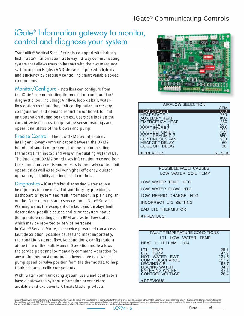
Tranquility® Vertical Stack Series is equipped with industry-fi rst, iGate® – Information Gateway – 2-way communicating system that allows users to interact with their water-source system in plain English AND delivers improved reliability and effi ciency by precisely controlling smart variable speed components.
Monitor/Confi gure – Installers can confi gure from the iGate® communicating thermostat or confi guration/diagnostic tool, including: Air fl ow, loop delta T, water-fl ow option confi guration, unit confi guration, accessory confi guration, and demand reduction (optional, to limit unit operation during peak times). Users can look up the current system status: temperature sensor readings and operational status of the blower and pump.
Precise Control – The new DXM2 board enables intelligent, 2-way communication between the DXM2 board and smart components like the communicating thermostat, fan motor, and vFlow® modulating water valve. The Intelligent DXM2 board uses information received from the smart components and sensors to precisely control unit operation as well as to deliver higher effi ciency, quieter operation, reliability and increased comfort.
Diagnostics – iGate® takes diagnosing water source heat pumps to a next level of simplicity, by providing a dashboard of system and fault information, in plain English, on the iGate thermostat or service tool. iGate® Service Warning warns the occupant of a fault and displays fault description, possible causes and current system status (temperature readings, fan RPM and water fl ow status) which may be reported to service personnel.In iGate® Service Mode, the service personnel can access fault description, possible causes and most importantly, the conditions (temp, fl ow, i/o conditions, confi guration) at the time of the fault. Manual Operation mode allows the service personnel to manually command operation for any of the thermostat outputs, blower speed, as well as pump speed or valve position from the thermostat, to help troubleshoot specifi c components.
With iGate® communicating system, users and contractors have a gateway to system information never before available and exclusive to ClimateMaster products.
AIRFLOW SELECTION CFMHEAT STAGE 1 600HEAT STAGE 2 750 AUXILIARY HEAT 850EMERGENCY HEAT 850COOL STAGE 1 525COOL STAGE 2 700COOL DEHUMID 1 425COOL DEHUMID 2 550CONTINUOUS FAN 350HEAT OFF DELAY 60COOL OFF DELAY 30 PREVIOUS NEXT
POSSIBLE FAULT CAUSESLOW WATER COIL TEMP
LOW WATER TEMP - HTGLOW WATER FLOW - HTGLOW REFRIG CHARGE - HTGINCORRECT LT1 SETTINGBAD LT1 THERMISTOR PREVIOUS
FAULT TEMPERATURE CONDITIONSLT1 LOW WATER TEMP
HEAT 1 11:11 AM 11/14LT1 TEMP 28.1LT2 TEMP 97.3HOT WATER EWT 121.5COMP DISCHARGE 157.7LEAVING AIR 92.7LEAVING WATER 34.9ENTERING WATER 42.1CONTROL VOLTAGE 26.4 PREVIOUS
iGate® Communicating Controls
iGate® Information gateway to monitor, control and diagnose your system

ClimateMaster works continually to improve its products. As a result, the design and specifi cations of each product at the time of order may be changed without notice and may not be as described herein. Please contact ClimateMaster's Customer Service Department at 1-405-745-6000 for specifi c information on the current design and specifi cations. Statements and other information contained herein are not express warranties and do not form the basis of any bargain between the parties, but are merely ClimateMaster's opinion or commendation of its products. The latest version of this document is available at climatemaster.com.
Page ______ of ______LC994 - 7
vFlow® Modulating Water Valve (option)
ATC Communicating Thermostat
DXM2
Two-Way Communication
One-Way Communication
Sensors (6)LTI, LT2, LAT
EWT, LWT, COMPR Discharge Diagnostic
Tool
Or
vFlow® Motorized modulating water valve delivers variable water-fl ow, controlled by DXM2 control, based on loop water tem-perature delta
vFlow® Internal Variable Water FlowIndustry-fi rst, Built-in vFlow® provides an ultra-high-effi cient internal water fl ow system. It saves installers time and labor by avoiding installing bulky valves or fl ow regulators. Multi-unit installations are also much simpler with vFlow® systems, as the units automatically adjust water fl ow across the system.
vFlow® is enabled by iGate®, which facilitates intelligent communication between the thermostat, DXM2 control, sensors and modulating valve to make true variable water fl ow a reality.
In applications using vFlow® with modulating valve, when the motorized modulating valve slows down the external pump, consumes fewer watts, thus saving more energy.
vFlow® delivers four main benefi ts: 1. One component replaces 2 way motorized valve and autofl ow regulator.2. Superior reliability by varying the water fl ow to deliver more stable operation.3. Higher cost savings by varying the fl ow (and pump watt consumption) to match the unit’s mode of operation. 4. Allows unit to safely operate in cooling mode or heating mode from 20°F to 120°F.
Modulating Water Valve Operation: When the unit is in cooling or heating, the DXM2 controller monitors the entering and leaving
water temperature.Depending on the water Delta T, the DXM2 sends a voltage signal to the valve which correlates to a percentage open to achieve the water fl ow needed. As conditions change the voltage signal will readjust the valve for the needed water fl ow.
The modulating water valve is factory set for a water delta T of 10F for cooling operation and 7F for heating operation. This default setting is estimated to be approximately 3 GPM of water fl ow per ton of load capacity. Installers can change the water fl ow by adjusting the delta T upward for lower fl ow or downward for higher fl ow by using the ATC thermostat or the ACDU service tool. Please see unit IOM for full instructions.
At low cooling EWT’s and high heating EWT’s the DXM2 software overrides the Delta T settings and adjusts the valve for a LWT of no less than 60F for cooling and no greater than 70F for heating.
Units with the modulating water valve will operate at EWT’s from 20F to 120F in BOTH cooling and heating. When there is no demand for cooling or heating, the valve will be fully closed or can be fi eld confi gured to remain slightly open allowing some water to pass through.
By controlling the water fl ow, the system will always operate at its optimal capacity and effi ciency.
ClimateMaster works continually to improve its products. As a result, the design and specifi cations of each product at the time of order may be changed without notice and may not be as described herein. Please contact ClimateMaster's Customer Service Department at 1-405-745-6000 for specifi c information on the current design and specifi cations. Statements and other information contained herein are not express warranties and do not form the basis of any bargain between the parties, but are merely ClimateMaster's opinion or commendation of its products. The latest version of this document is available at climatemaster.com.
Page ______ of ______LC994 - 8
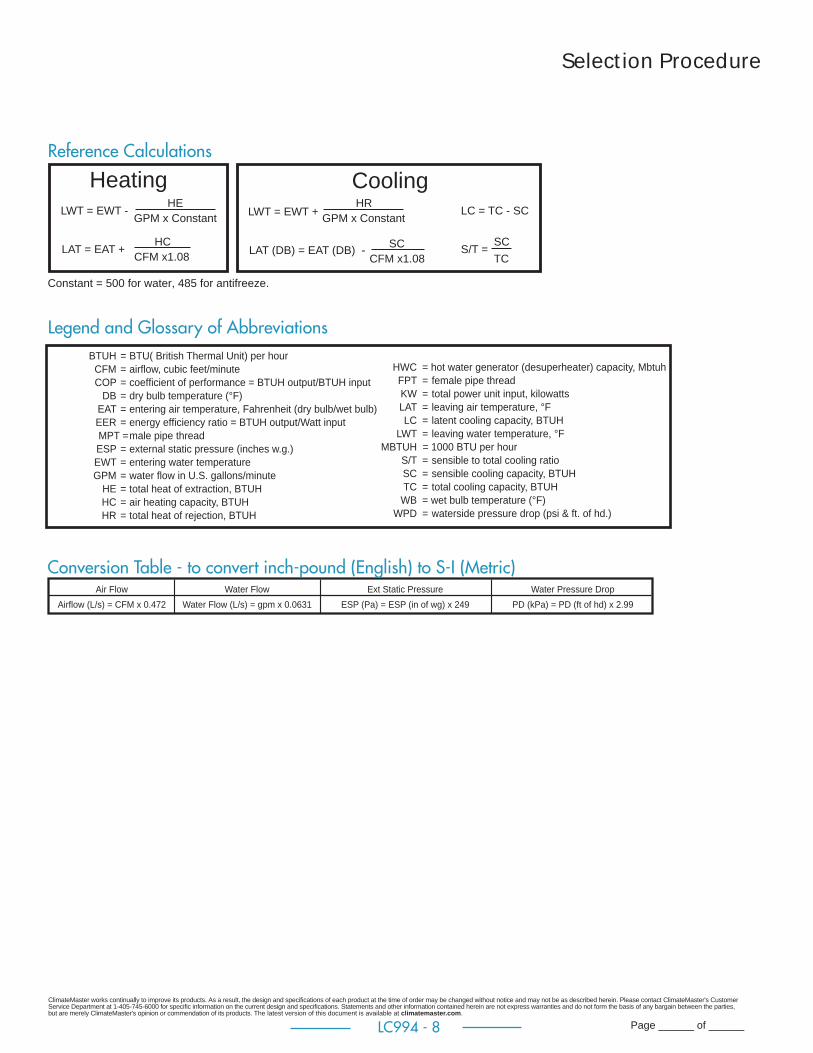
LWT = EWT -HE
GPM x ConstantHR
GPM x Constant
LAT = EAT +HC
CFM x1.08
LWT = EWT +
LAT (DB) = EAT (DB) - SCCFM x1.08
LC = TC - SC
S/T =SCTC
Heating Cooling
Constant = 500 for water, 485 for antifreeze.
Air Flow Water Flow Ext Static Pressure Water Pressure DropAirflow (L/s) = CFM x 0.472 Water Flow (L/s) = gpm x 0.0631 ESP (Pa) = ESP (in of wg) x 249 PD (kPa) = PD (ft of hd) x 2.99
Reference Calculations
BTUH = BTU( British Thermal Unit) per hour CFM = airfl ow, cubic feet/minute COP = coeffi cient of performance = BTUH output/BTUH input DB = dry bulb temperature (°F) EAT = entering air temperature, Fahrenheit (dry bulb/wet bulb) EER = energy effi ciency ratio = BTUH output/Watt input MPT = male pipe thread ESP = external static pressure (inches w.g.) EWT = entering water temperature GPM = water fl ow in U.S. gallons/minute HE = total heat of extraction, BTUH HC = air heating capacity, BTUH HR = total heat of rejection, BTUH
HWC = hot water generator (desuperheater) capacity, Mbtuh FPT = female pipe thread KW = total power unit input, kilowatts LAT = leaving air temperature, °F LC = latent cooling capacity, BTUH LWT = leaving water temperature, °FMBTUH = 1000 BTU per hour S/T = sensible to total cooling ratio SC = sensible cooling capacity, BTUH TC = total cooling capacity, BTUH WB = wet bulb temperature (°F) WPD = waterside pressure drop (psi & ft. of hd.)
Conversion Table - to convert inch-pound (English) to S-I (Metric)
Legend and Glossary of Abbreviations
Selection Procedure
ClimateMaster works continually to improve its products. As a result, the design and specifi cations of each product at the time of order may be changed without notice and may not be as described herein. Please contact ClimateMaster's Customer Service Department at 1-405-745-6000 for specifi c information on the current design and specifi cations. Statements and other information contained herein are not express warranties and do not form the basis of any bargain between the parties, but are merely ClimateMaster's opinion or commendation of its products. The latest version of this document is available at climatemaster.com.
Page ______ of ______LC994 - 9
Selection ProcedureStep 1 Determine the actual heating and cooling loads at the
desired dry bulb and wet bulb conditions.
Step 2 Obtain the following de sign parameters: Entering water
temperature, water fl ow rate in GPM, air fl ow in CFM,
water fl ow pressure drop and design wet and dry bulb
temperatures. Air fl ow CFM should be between 300 and
500 CFM per ton. Unit water pressure drop should be
kept as close as possible to each other to make water
balancing easier. Go to the ap pro pri ate tables and fi nd
the proper indicated water fl ow and water tem per a ture.
Step 3 Select a unit based on total and sensible cooling
conditions. Select a unit which is closest to, but no larger
than, the actual cooling load.
Step 4 Enter tables at the design water fl ow and water
temperature. Read the total and sensible cooling
capacities (Note: interpolation is per mis si ble,
ex trap o la tion is not).
Step 5 Read the heating capacity. If it exceeds the design criteria
it is acceptable. It is quite normal for Water-Source Heat
Pumps to be selected on cooling capacity only since
the heating output is usually greater than the cooling
capacity.
Step 6 Determine the correction factors associated with the
variable factors of dry bulb, wet bulb, and air fl ow.
Corrected Total Cooling = tabulated total cooling x wet
bulb correction x air fl ow correction.
Corrected Sensible Cooling = tabulated sensible cooling x
wet/dry bulb correction, and air fl ow correction.
Step 7 Compare the corrected capacities to the load
re quire ments. Normally if the capacities are within 10%
of the loads, the equipment is ac cept able. It is better to
undersize than oversize, as undersizing improves humidity
control, reduces sound levels and extends the life of the
equip ment.
Step 8 When completed, calculate water temperature rise and
assess the selection. If the units selected are not within
10% of the load cal cu la tions, then review what effect
chang ing the GPM, water temperature and/or air fl ow and
air tem per a ture would have on the corrected capacities.
If the desired capacity cannot be achieved, select the
next larger or smaller unit and repeat the procedure.
Remember, when in doubt, undersize slightly for best
performance.
Example Equipment Selection For Cool ing
Step 1 Load Determination:
Assume we have determined that the appropriate cooling load at
the desired dry bulb 80°F and wet bulb 65°F con di tions is
as follows
Total Cooling ............................................................ 17,000 BTUH
Sensible Cooling...................................................... 12,000 BTUH
Entering Air Temp .......................80°F Dry Bulb / 65°F Wet Bulb
Step 2 Design Conditions:
Similarly, we have also obtained the following design pa ram e ters:
Entering Water Temp ............................................................. 90°F
Water Flow (Based upon 10°F rise in temp.) ................. 5.1 GPM
Air Flow at ESP Unit ................................ 630 CFM (90% of rated)
Step 3, 4 & 5 HP Selection:
After making our preliminary selection (TSM18 with PSC motor),
we enter the tables at design water fl ow and water tem per a ture
and read Total Cooling, Sens. Cooling and Heat of Rej. ca pac i ties:
Total Cooling ...........................................................18,350 BTUH
Sensible Cooling ...................................................... 13,210 BTUH
Heat of Rejection ..................................................... 22,470 BTUH
Step 6 & 7 Entering Air and Airfl ow Corrections:
Next, we determine our correction factors.
Table Ent Air Air Flow Cor rect ed
Corrected Total Cooling = 18,350 x 0.975 x 0.971 = 17,372
Corrected Sens Cooling = 13,210 x 0.999 x 0.932 = 12,299
Corrected Heat of Reject = 22,470 x 0.982 x 0.979 = 21,602
Step 8 Water Temperature Rise Calculation & As sess ment:
Actual Temperature Rise ...................................................... 8.8°F
When we compare the Corrected Total Cooling and Corrected
Sensible Cooling fi gures with our load re quire ments stated in Step
1, we discover that our selection is within +/- 10% of our sensible
load requirement. Fur ther more, we see that our Cor rect ed Total
Cooling fi gure is slightly undersized as recommended, when
compared to the actual in di cat ed load.

ClimateMaster works continually to improve its products. As a result, the design and specifi cations of each product at the time of order may be changed without notice and may not be as described herein. Please contact ClimateMaster's Customer Service Department at 1-405-745-6000 for specifi c information on the current design and specifi cations. Statements and other information contained herein are not express warranties and do not form the basis of any bargain between the parties, but are merely ClimateMaster's opinion or commendation of its products. The latest version of this document is available at climatemaster.com.
Page ______ of ______LC994 - 10
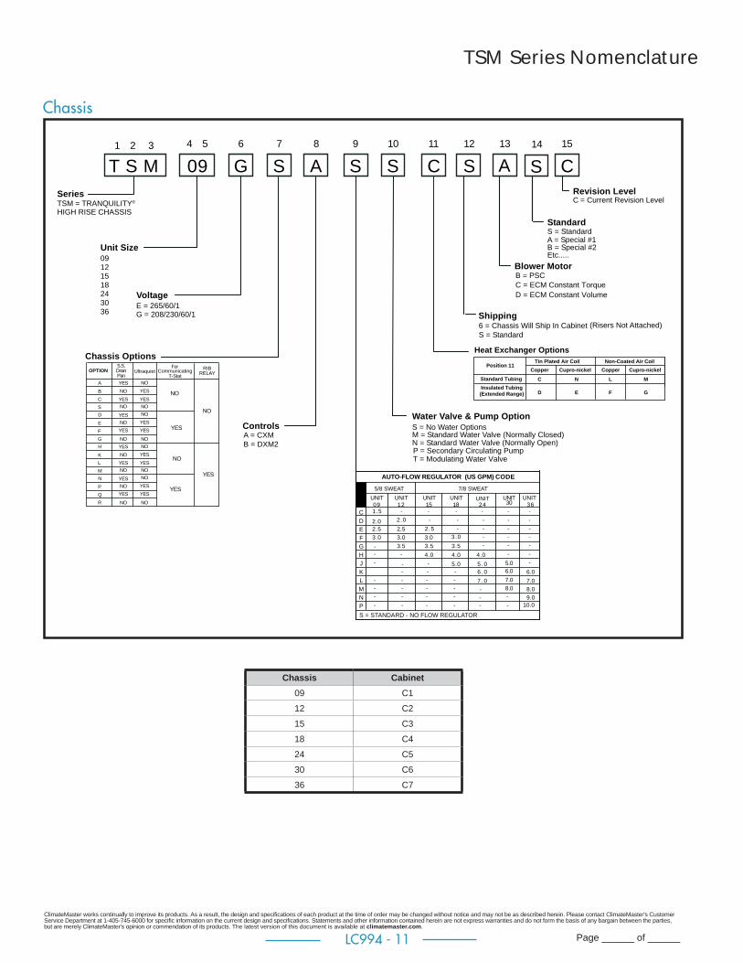
TSM Series Nomenclature
Cabinet
0
S.S. DRAIN PANOPTION
AB
BREAKERDISCONNECT SWITCHOPTION
0 NO OPTIONS
2
GVolt/Hertz/PhazeOPTION
208/230/60/1E 265/60/1
34
ISP / BREAKER
C
ABC
1
1”1”1”1”2”2”2”2”
OPTION DIGIT 9OPTION
0 = SLAVE/NONE1 = STANDARD2 = MASTER
0, 6
1, 2, 3 , 4, 5
DIGIT 10OPTION
0
OPTION
0 = NONE
2 = LEFT BACK3 = RIGHT BACK
VERTICALPKG
NO
YES
HORIZONTALPKG
4 = LEFT SIDE5 = RIGHT SIDE
YES
YES
NO
NO
YES
NO
NO
YES
ABCD
88”80”OPTION ISO PAD
NO NO
NONO
NO
NO
NO
NO
YES YESYES
YESYES
YES
YES
YES
NONO
NO NOYESYES
YES
NO
NONO
NO
NOYES
YES
YESYES YES
1 1NG NA 0 0 0 0 D 2 83 5 7 10 11 12 13 14 15
0 = STANDARDTYPE A, B , C etc.... = SPECIAL 1, 2, 3 etc....
REVISION LEVEL04
06
D = CURRENT REVISION
OPTIONS
POWER TERMINATION
VOLTAGE
RISER: RISER BALL VALVE OPTIONS4 = Ball Valve, Union
19
PREMIUM SEAL
MISCELLANEOUS CABINET OPTIONS
1 = Field to Configure Supply Air Openings + 15’ Whip0 = Field to Configure Supply Air Openings + No Whip
A = Factory Configure Supply Air Openings + Dust Protection + No WhipB = Factory Configure Supply Air Openings + Dust Protection + 15’ WhipC = Factory Configure Supply Air Openings + Dust Protection + 25’ WhipD = Factory Configure Supply Air Openings + Dust Protection + 35’ Whip
2 = Field to Configure Supply Air Openings + 25’ Whip3 = Field to Configure Supply Air Openings + 35’ Whip4 = Factory Configure Supply Air Openings + No Whip5 = Factory Configure Supply Air Openings + 15’ Whip6 = Factory Configure Supply Air Openings + 25’ Whip7 = Factory Configure Supply Air Openings + 35’ Whip
C 1
FILTER SIZE
RISER STYLE OPTIONSRISER LOCATION/PACKAGING OPTIONS
OPTION
BCDEFGHJ
A0
KLM
DISCHARGEC-SERIES
80”TSM
NO
YES
C-SERIES88”
TSM
NPQRS
NONEBACK SMALLBACK LARGEFRONT SMALLFRONT LARGETOPBACK SMALL & TOPBACK LARGE & TOPFRONT SMALL & TOPFRONT LARGE & TOP
UNIT SIZE09-18 TOP
UNIT SIZE15-16 TOP
UNIT SIZE24-36 TOP
N/A
12 X 12 14 X 14 16 X 16
N/A
12 X 12 14 X 14 16 X 16
YES
NOYESNONOYESYESNONOYES
YES
BACK/FRONT/TOP DISCHARGE OPTIONS
BACK SMALL & FRONT SMALLBACK LARGE & FRONT LARGEBACK SMALL & FRONT LARGEBACK LARGE & FRONT SMALLBACK SMALL & FRONT SMALL W/TOPBACK LARGE & FRONT LARGE W/TOPBACK SMALL & FRONT LARGE W/TOPBACK LARGE & FRONT SMALL W/TOP
CABINET HEIGHT
ALL OPTIONS AVAILABLE
1 = 092 = 12
4 = 185 = 246 = 307 = 36
UNIT SIZE
3 = 15
SERIESTranquility High Rise Cabinet for TSM
1 = SHIPPED SEPERATELY
6 = CHASSIS SHIPPED IN CABINET
VALVE ASM QTY 2SHIPPED IN CABINET
VALVE ASM QTY 2SHIPPED W/RISERS
OPTION
BCDEFGH
A0
DISCHARGE
NONERIGHT SMALLRIGHT LARGELEFT SMALLLEFT LARGE
SIDE DISCHARGE OPTIONS
RIGHT SMALL & LEFT SMALLRIGHT LARGE & LEFT LARGERIGHT SMALL & LEFT LARGERIGHT LARGE & LEFT SMALL
5 = Ball Valves, Sweat N = None
M = MPCL = LON
NO
M
M
L
L
NO
NO
OPTION
CDLMNPRS12345
S=SURFACER =REMOTE
W = WALL SENSORA = ADA
BA
YESNO
NO
NO
NO
PSCSTANDARD
YESYES
NOYES
YES
NONO
YES
YES
YES
YESNO
NO
NO
ECM CONSTANTVOLUME
(DXM2 ONLY)
ECM CONSTANTTORQUE
A
A
R
RS
W
W
RS
S
HARNESS CONTROLS
ClimateMaster works continually to improve its products. As a result, the design and specifi cations of each product at the time of order may be changed without notice and may not be as described herein. Please contact ClimateMaster's Customer Service Department at 1-405-745-6000 for specifi c information on the current design and specifi cations. Statements and other information contained herein are not express warranties and do not form the basis of any bargain between the parties, but are merely ClimateMaster's opinion or commendation of its products. The latest version of this document is available at climatemaster.com.
Page ______ of ______LC994 - 11
Chassis
TSM = TRANQUILITY®
T S M1 2 3
09121518243036
09 GSeries
Unit Size
Voltage
S S S C S A4 5 6 7 9 10 11 12 13
Water Valve & Pump OptionS = No Water OptionsM = Standard Water Valve (Normally Closed)N = Standard Water Valve (Normally Open)P = Secondary Circulating Pump
Shipping
Blower Motor
Heat Exchanger Options
HIGH RISE CHASSIS
Chassis Options
A8
Controls
S C14 15
StandardS = Standard
Revision LevelC = Current Revision Level
6 = Chassis Will Ship In CabinetS = Standard
B = PSC C = ECM Constant TorqueD = ECM Constant Volume
7/8 SWEAT
3.0
2.52.0
UNIT09
E
HGF
AUTO-FLOW REGULATOR (US GPM) CODE
DC
5/8 SWEAT
4.0
3.5
UNIT18
2.5
-
3.5
3.0
UNIT12
UNIT24
UNIT30
UNIT36
K
PNML
-
-
-
7 . 0
6 . 0
8.0
-
-
7.0
6.0J 5.0- 5 . 0 5.0
6.0
8.0
9.0
7.0
S = STANDARD - NO FLOW REGULATOR
-
-
4.0
3.5
UNIT15
--
-
3.0
4.0
1.5 - - - - - -
2 .0 - - - - -
2 .5 - - - -
3 .0 - - -
- - -
- -
-
- - - - -
- - - -
- - - -- -
-
-
-
10.0
A = Special #1B = Special #2Etc.....
E = 265/60/1G = 208/230/60/1
A = CXM B = DXM2
Position 11Copper
C
D E
N L
F G
M
Cupro-nickel Cupro-nickelCopper
Standard Tubing
Tin Plated Air Coil Non-Coated Air Coil
Insulated Tubing(Extended Range)
(Risers Not Attached)
OPTIONS.S.DrainPan
B
C
S
A
Ultraquiet
NOYES
E
F
G
D
CommunicatingT-Stat
For
NONO
NONO
NO
NO
NO
YES
YES
YES
YES
YES
YES
YES
RIBRELAY
NO
K
L
M
H NOYES
P
Q
R
N
NONO
NONO
NO
NO
NO
YES
YES
YES
YES
YES
YES
YES
YES
NO
YES
NO
YES
T = Modulating Water Valve
TSM Series Nomenclature
Chassis Cabinet09 C1
12 C2
15 C3
18 C4
24 C5
30 C6
36 C7

ClimateMaster works continually to improve its products. As a result, the design and specifi cations of each product at the time of order may be changed without notice and may not be as described herein. Please contact ClimateMaster's Customer Service Department at 1-405-745-6000 for specifi c information on the current design and specifi cations. Statements and other information contained herein are not express warranties and do not form the basis of any bargain between the parties, but are merely ClimateMaster's opinion or commendation of its products. The latest version of this document is available at climatemaster.com.
Page ______ of ______LC994 - 12
A V H R L 1 S F S 01 2 3 4 5 6 7 8 9 11
A12
S13
ACCESSORY VS RETURN AIR PANEL
COLOR
INSULATION TYPE STYLE
REVISION LEVEL
S = STANDARD
F10
STANDARDS = STANDARD
UNIT SIZEOPTION
1
2
3
4
S = STANDARD (POLAR ICE)W = BRIGHT WHITE
AVHRL = L-PANEL
F = FIBERGLASS
TSM/TSL
09, 12,
A = CURRENT REVISION
RESERVED FOR FUTURE USE0 = STANDARD
COMPONENTF = FRAMEP = PANEL
24
30, 36
15, 18
TSM Series Accessory Nomenclature
Return Air Panel "L" Style
Return Air Panel "G' Style
A V H S 1 S F S S1 2 3 4 6 7 8 9 11
ACCESSORY VHS RETURN AIR PANEL
COLOR
INSULATION TYPE
STYLE
REVISION LEVEL
S = STANDARD (20 GA. SHEET METAL)
A = DOOR w/ADA TSTAT MOUNTINGB = DOOR w/ADA TSTAT MOUNTING & GRILLEC = DOOR w/ADA TSTAT MOUNTING & LOCKD = DOOR w/ADA TSTAT MOUNTING, GRILLE, & LOCK
L = DOOR w/KEY LOCKS (18 GA. SHEET METAL)
G = DOOR w/GRILLE (20 GA. SHEET METAL) 24-36
N10
STANDARDS = STANDARD
UNIT SIZEOPTION
1
2
3
K = DOOR w/KEY LOCKS & GRILLE (18 GA. SHEET METAL)S = STANDARD (POLAR ICE)W = BRIGHT WHITE
F = FIBERGLASS
TSM/TSL
09, 12,
N = CURRENT REVISION TSM (”G” PANEL)
24, 30, 36
TYPE“G”
DESCRIPTION
Removable
G5
15, 18
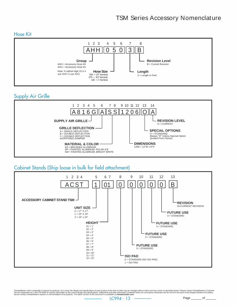
ClimateMaster works continually to improve its products. As a result, the design and specifi cations of each product at the time of order may be changed without notice and may not be as described herein. Please contact ClimateMaster's Customer Service Department at 1-405-745-6000 for specifi c information on the current design and specifi cations. Statements and other information contained herein are not express warranties and do not form the basis of any bargain between the parties, but are merely ClimateMaster's opinion or commendation of its products. The latest version of this document is available at climatemaster.com.
Page ______ of ______LC994 - 13
TSM Series Accessory Nomenclature
15
ACCESSORY CABINET STAND TSM
017
08
010
09
UNIT SIZE
ACST1 2 3 4
ISO PAD
FUTURE USE
FUTURE USE
011
012
B13
FUTURE USE
FUTURE USE
REVISION
HEIGHT
6
0 = 17” X 17”
2 = 24” x 24”1 = 19” X 19”
01 = 1”
03 = 3”02 = 2”
04 = 4”05 = 5”06 = 6”07 = 7”08 = 8”09 = 9”10 = 10”11 = 11”12 = 12”
0 = STANDARD
0 = STANDARD (NO ISO PAD)1 = ISO PAD
0 = STANDARD
0 = STANDARD
0 = STANDARD
B=CURRENT REVISION
Supply Air Grille
Cabinet Stands (Ship loose in bulk for fi eld attachment)
A 8 1 6 G A 1 2 0 6S S1 2 3 4 5 9 10 11 127 8
SUPPLY AIR GRILLE
MATERIAL & COLOR DIMENSIONS
C = DOUBLE DEFLECTION w/OPPOSED DAMPER
GRILLE DEFLECTION
SS = BRUSHED ALUMINUM
A = SINGLE DEFLECTIONB = DOUBLE DEFLECTION
6
1206 = 12"W x 6"HSP = PAINTED ALUMINUM, POLAR ICESW = PAINTED ALUMINUM, BRIGHT WHITE
O13
SPECIAL OPTIONSO = STANDARDAlways "O" Unless Special OptionQuoted From Factory
A14
REVISION LEVELA = CURRENT
0 5 0A H H B31 2 3 4 5 6 8
GroupAHH = Accessory Hose KitAHU = Accessory Hose KitNote: If cabinet digit 10 is 4 use AHH; 5 use AHU
Hose Size050 = 1/2” Nominal
Length
Revision Level
7
075 = 3/4” Nominal100 = 1” Nominal
B = Current Revision
3 = Length in Feet
Hose Kit

ClimateMaster works continually to improve its products. As a result, the design and specifi cations of each product at the time of order may be changed without notice and may not be as described herein. Please contact ClimateMaster's Customer Service Department at 1-405-745-6000 for specifi c information on the current design and specifi cations. Statements and other information contained herein are not express warranties and do not form the basis of any bargain between the parties, but are merely ClimateMaster's opinion or commendation of its products. The latest version of this document is available at climatemaster.com.
Page ______ of ______LC994 - 14
Performance Data – AHRI/ASHRAE/ISO 13256-1
Model with ECM
Motor
Water Loop Heat Pump Ground Loop Heat PumpCooling 86°F Heating 68°F Cooling 77°F Heating 32°F
Capacity
Btuh
EER
Btuh/W
Capacity
BtuhCOP
Capacity
Btuh
EER
Btuh/W
Capacity
BtuhCOP
TSM09 9200 14.3 12200 5.4 9700 16.2 7100 3.3TSM12 11800 14.1 15200 5.3 12100 16.8 9000 3.2TSM15 14600 15.9 17500 5.3 15500 18.8 11000 3.6TSM18 18000 15.2 22200 5.1 18500 17.3 13200 3.3TSM24 25000 15.7 32500 5.1 26500 18.5 18200 3.5TSM30 28000 15.1 34500 5.0 29000 17.6 22200 3.6TSM36 35000 14.6 40500 5.0 36000 16.5 25500 3.5
Model with PSC
Motor
Water Loop Heat Pump Ground Loop Heat PumpCooling 86°F Heating 68°F Cooling 77°F Heating 32°F
Capacity
Btuh
EER
Btuh/W
Capacity
BtuhCOP
Capacity
Btuh
EER
Btuh/W
Capacity
BtuhCOP
TSM09 9200 13.5 12200 5.0 9700 14.9 7100 3.2TSM12 11800 13.7 15200 4.9 12100 15.0 9000 3.2TSM15 14300 13.3 18000 4.8 15200 15.6 11500 3.3TSM18 17300 13.2 22500 4.8 18400 15.1 13500 3.2TSM24 25000 14.4 32500 4.9 26500 16.8 18400 3.4TSM30 27500 13.4 34500 4.7 28500 15.2 22000 3.3TSM36 35000 14.1 40500 4.9 36000 16.2 25500 3.4
Cooling capacities based upon 80.6°F DB, 66.2°F WB entering air temperatureHeating capacities based upon 68°F DB, 59°F WB entering air temperatureAll units AHRI/ISO/ASHRAE 13256-1 rated on high speed motor TAPAll ratings based upon operation at lower voltage of dual voltage rated models
ASHRAE/AHRI/ISO 13256-1. English (I-P) Units
Modelwith ECM
Motor
Water Loop Heat Pump Ground Loop Heat PumpCooling 30°C Heating 20°C Cooling 25°C Heating 0°C
CapacitykW
EERW/W
CapacitykW COP Capacity
kWEERW/W
CapacitykW COP
TSM09 2.70 4.2 3.58 5.4 2.84 4.8 2.08 3.3
TSM12 3.46 4.1 4.46 5.3 3.55 4.9 2.64 3.2
TSM15 4.28 4.7 5.13 5.3 4.55 5.5 3.23 3.6
TSM18 5.28 4.5 6.51 5.1 5.43 5.1 3.87 3.3
TSM24 7.33 4.6 9.53 5.1 7.77 5.4 5.34 3.5
TSM30 8.21 4.4 10.12 5 8.50 5.2 6.51 3.6
TSM36 10.26 4.3 11.88 5 10.56 4.8 7.48 3.5
Modelwith PSC
Motor
Water Loop Heat Pump Ground Loop Heat PumpCooling 30°C Heating 20°C Cooling 25°C Heating 0°C
CapacitykW
EERW/W
CapacitykW COP Capacity
kWEERW/W
CapacitykW COP
TSM09 2.70 4.0 3.58 5 2.84 4.4 2.08 3.2
TSM12 3.46 4.0 4.46 4.9 3.55 4.4 2.64 3.2
TSM15 4.19 3.9 5.28 4.8 4.46 4.6 3.37 3.3
TSM18 5.07 3.9 6.60 4.8 5.40 4.4 3.96 3.2
TSM24 7.33 4.2 9.53 4.9 7.77 4.9 5.40 3.4
TSM30 8.06 3.9 10.12 4.7 8.36 4.5 6.45 3.3
TSM36 10.26 4.1 11.88 4.9 10.56 4.8 7.48 3.4
Cooling capacities based upon 27°C DB, 19°C WB entering air temperatureHeating capacities based upon 20°C DB, 15°C WB entering air temperatureAll units AHRI/ISO/ASHRAE 13256-1 rated on high speed motor TAPAll ratings based upon operation at lower voltage of dual voltage rated models
ASHRAE/AHRI/ISO 13256-1. Metric (S-I) Units
ClimateMaster works continually to improve its products. As a result, the design and specifi cations of each product at the time of order may be changed without notice and may not be as described herein. Please contact ClimateMaster's Customer Service Department at 1-405-745-6000 for specifi c information on the current design and specifi cations. Statements and other information contained herein are not express warranties and do not form the basis of any bargain between the parties, but are merely ClimateMaster's opinion or commendation of its products. The latest version of this document is available at climatemaster.com.
Page ______ of ______LC994 - 15
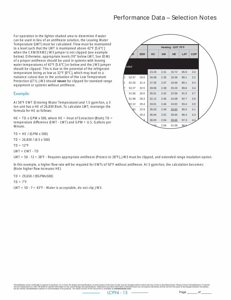
Performance Data – Selection Notes
For operation in the lighter shaded area to determine if water can be used in lieu of an antifreeze solution, the Leaving Water Temperature (LWT) must be calculated. Flow must be maintained to a level such that the LWT is maintained above 42°F [5.6°C] when the CXM/DXM2 JW3 jumper is not clipped (see example below). Otherwise, appropriate levels (10° below LWT, See IOM) of a proper antifreeze should be used in systems with leaving water temperatures of 42°F [5.6°C] or below and the JW3 jumper should be clipped. This is due to the potential of the refrigerant temperature being as low as 32°F [0°C], which may lead to a nuisance cutout due to the activation of the Low Temperature Protection (LT1). JW3 should never be clipped for standard range equipment or systems without antifreeze.
Example:
At 50°F EWT (Entering Water Temperature) and 1.5 gpm/ton, a 3 ton unit has a HE of 26,830 Btuh. To calculate LWT, rearrange the formula for HE as follows:
HE = TD x GPM x 500, where HE = Heat of Extraction (Btuh); TD = temperature difference (EWT - LWT) and GPM = U.S. Gallons per Minute.
TD = HE / (GPM x 500)
TD = 26,830 / (4.5 x 500)
TD = 12°F
LWT = EWT - TD
LWT = 50 - 12 = 38°F - Requires appropriate antifreeze (Protect to 28°F), JW3 must be clipped, and extended range insulation option.
In this example, a higher fl ow rate will be required for EWTs of 50°F without antifreeze. At 3 gpm/ton, the calculation becomes:(Note higher fl ow increases HE)
TD = 29,650 / (9GPMx500)
TD = 7°F
LWT = 50 - 7 = 43°F - Water is acceptable, do not clip JW3.
/67°F Heating - EAT 70°F
W HR EER HC kW HE LAT COP
mended
23.28 2.31 15.72 85.9 3.0
62 52.07 29.0 26.08 2.35 18.36 88.1 3.2
51 52.26 31.3 27.35 2.37 19.56 89.1 3.4
47 52.27 32.5 28.06 2.38 20.23 89.6 3.4
77 51.56 26.0 30.51 2.42 22.56 91.5 3.7
65 51.98 28.3 32.12 2.45 24.08 92.7 3.8
60 52.12 29.4 33.01 2.46 24.92 93.4 3.9
94 50.82 22.9 35.03 2.49 26.83 95.0 4.1
80 51.40 25.3 36.94 2.52 28.65 96.4 4.3
74 51.65 26.4 38.00 2.54 29.65 97.3 4.4
5 49.89 19.9 39.53 2.56 31.09 98.4 4.5
ClimateMaster works continually to improve its products. As a result, the design and specifi cations of each product at the time of order may be changed without notice and may not be as described herein. Please contact ClimateMaster's Customer Service Department at 1-405-745-6000 for specifi c information on the current design and specifi cations. Statements and other information contained herein are not express warranties and do not form the basis of any bargain between the parties, but are merely ClimateMaster's opinion or commendation of its products. The latest version of this document is available at climatemaster.com.
Page ______ of ______LC994 - 16
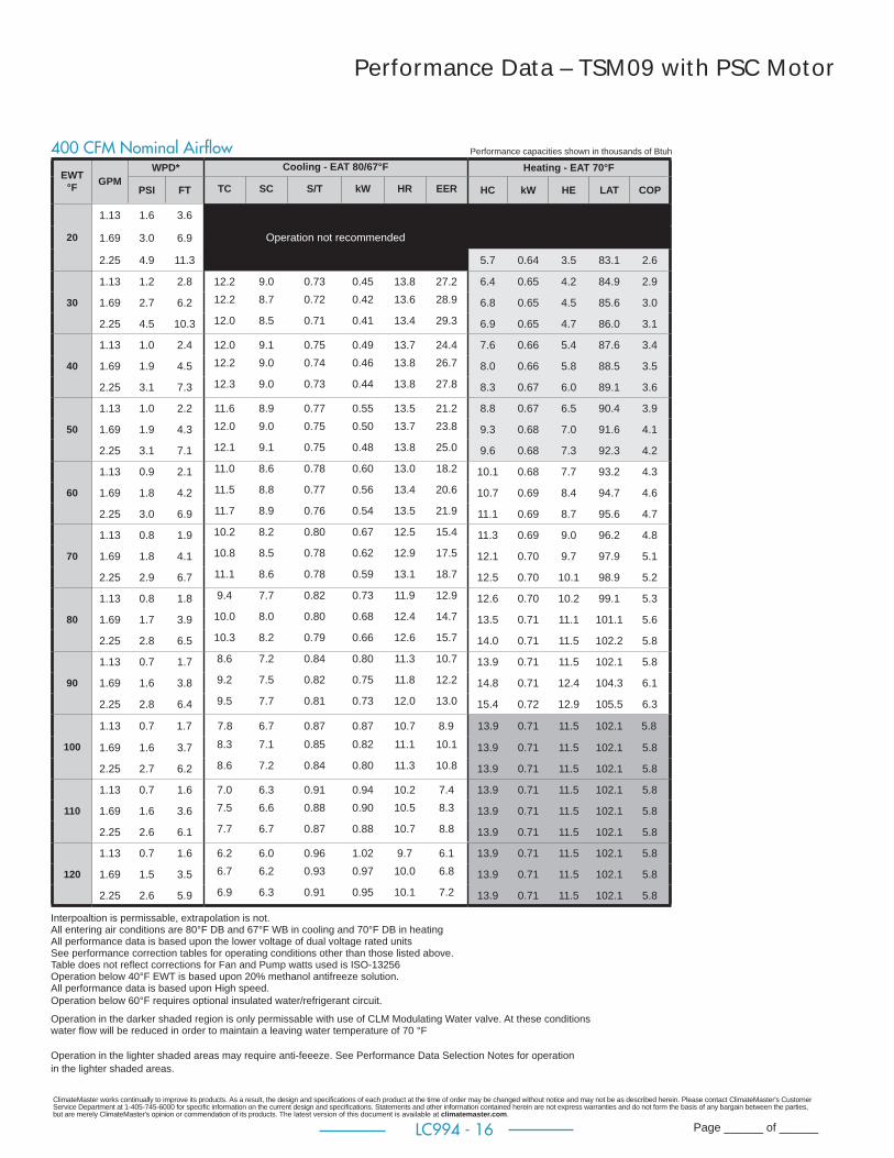
Performance Data – TSM09 with PSC Motor
EWT °F GPM
WPD* Cooling - EAT 80/67°F Heating - EAT 70°F
PSI FT TC SC S/T kW HR EER HC kW HE LAT COP
20
1.13 1.6 3.6
Operation not recommended1.69 3.0 6.9
2.25 4.9 11.3 5.7 0.64 3.5 83.1 2.6
30
1.13 1.2 2.8 12.2 9.0 0.73 0.45 13.8 27.2 6.4 0.65 4.2 84.9 2.9
1.69 2.7 6.2 12.2 8.7 0.72 0.42 13.6 28.9 6.8 0.65 4.5 85.6 3.0
2.25 4.5 10.3 12.0 8.5 0.71 0.41 13.4 29.3 6.9 0.65 4.7 86.0 3.1
40
1.13 1.0 2.4 12.0 9.1 0.75 0.49 13.7 24.4 7.6 0.66 5.4 87.6 3.4
1.69 1.9 4.5 12.2 9.0 0.74 0.46 13.8 26.7 8.0 0.66 5.8 88.5 3.5
2.25 3.1 7.3 12.3 9.0 0.73 0.44 13.8 27.8 8.3 0.67 6.0 89.1 3.6
50
1.13 1.0 2.2 11.6 8.9 0.77 0.55 13.5 21.2 8.8 0.67 6.5 90.4 3.9
1.69 1.9 4.3 12.0 9.0 0.75 0.50 13.7 23.8 9.3 0.68 7.0 91.6 4.1
2.25 3.1 7.1 12.1 9.1 0.75 0.48 13.8 25.0 9.6 0.68 7.3 92.3 4.2
60
1.13 0.9 2.1 11.0 8.6 0.78 0.60 13.0 18.2 10.1 0.68 7.7 93.2 4.3
1.69 1.8 4.2 11.5 8.8 0.77 0.56 13.4 20.6 10.7 0.69 8.4 94.7 4.6
2.25 3.0 6.9 11.7 8.9 0.76 0.54 13.5 21.9 11.1 0.69 8.7 95.6 4.7
70
1.13 0.8 1.9 10.2 8.2 0.80 0.67 12.5 15.4 11.3 0.69 9.0 96.2 4.8
1.69 1.8 4.1 10.8 8.5 0.78 0.62 12.9 17.5 12.1 0.70 9.7 97.9 5.1
2.25 2.9 6.7 11.1 8.6 0.78 0.59 13.1 18.7 12.5 0.70 10.1 98.9 5.2
80
1.13 0.8 1.8 9.4 7.7 0.82 0.73 11.9 12.9 12.6 0.70 10.2 99.1 5.3
1.69 1.7 3.9 10.0 8.0 0.80 0.68 12.4 14.7 13.5 0.71 11.1 101.1 5.6
2.25 2.8 6.5 10.3 8.2 0.79 0.66 12.6 15.7 14.0 0.71 11.5 102.2 5.8
90
1.13 0.7 1.7 8.6 7.2 0.84 0.80 11.3 10.7 13.9 0.71 11.5 102.1 5.8
1.69 1.6 3.8 9.2 7.5 0.82 0.75 11.8 12.2 14.8 0.71 12.4 104.3 6.1
2.25 2.8 6.4 9.5 7.7 0.81 0.73 12.0 13.0 15.4 0.72 12.9 105.5 6.3
100
1.13 0.7 1.7 7.8 6.7 0.87 0.87 10.7 8.9 13.9 0.71 11.5 102.1 5.8
1.69 1.6 3.7 8.3 7.1 0.85 0.82 11.1 10.1 13.9 0.71 11.5 102.1 5.8
2.25 2.7 6.2 8.6 7.2 0.84 0.80 11.3 10.8 13.9 0.71 11.5 102.1 5.8
110
1.13 0.7 1.6 7.0 6.3 0.91 0.94 10.2 7.4 13.9 0.71 11.5 102.1 5.8
1.69 1.6 3.6 7.5 6.6 0.88 0.90 10.5 8.3 13.9 0.71 11.5 102.1 5.8
2.25 2.6 6.1 7.7 6.7 0.87 0.88 10.7 8.8 13.9 0.71 11.5 102.1 5.8
120
1.13 0.7 1.6 6.2 6.0 0.96 1.02 9.7 6.1 13.9 0.71 11.5 102.1 5.8
1.69 1.5 3.5 6.7 6.2 0.93 0.97 10.0 6.8 13.9 0.71 11.5 102.1 5.8
2.25 2.6 5.9 6.9 6.3 0.91 0.95 10.1 7.2 13.9 0.71 11.5 102.1 5.8
Performance capacities shown in thousands of Btuh400 CFM Nominal Airfl ow
Interpoaltion is permissable, extrapolation is not. All entering air conditions are 80°F DB and 67°F WB in cooling and 70°F DB in heating All performance data is based upon the lower voltage of dual voltage rated units See performance correction tables for operating conditions other than those listed above. Table does not refl ect corrections for Fan and Pump watts used is ISO-13256 Operation below 40°F EWT is based upon 20% methanol antifreeze solution. All performance data is based upon High speed.Operation below 60°F requires optional insulated water/refrigerant circuit. Operation in the darker shaded region is only permissable with use of CLM Modulating Water valve. At these conditions water fl ow will be reduced in order to maintain a leaving water temperature of 70 °F
Operation in the lighter shaded areas may require anti-feeeze. See Performance Data Selection Notes for operation in the lighter shaded areas.

ClimateMaster works continually to improve its products. As a result, the design and specifi cations of each product at the time of order may be changed without notice and may not be as described herein. Please contact ClimateMaster's Customer Service Department at 1-405-745-6000 for specifi c information on the current design and specifi cations. Statements and other information contained herein are not express warranties and do not form the basis of any bargain between the parties, but are merely ClimateMaster's opinion or commendation of its products. The latest version of this document is available at climatemaster.com.
Page ______ of ______LC994 - 17
Performance Data – TSM12 with PSC Motor
Performance capacities shown in thousands of Btuh450 CFM Nominal Airfl ow
EWT °F GPM
WPD* Cooling - EAT 80/67°F Heating - EAT 70°F
PSI FT TC SC S/T kW HR EER HC kW HE LAT COP
20
1.50 2.3 5.3Operation not recommended 2.25 4.7 10.8
3.00 7.8 18.0 7.0 0.79 4.3 84.4 2.6
30
1.50 2.1 4.7 14.5 9.7 0.67 0.55 16.4 26.4 8.1 0.81 5.4 86.7 2.9
2.25 4.3 9.9 14.2 9.3 0.65 0.52 16.0 27.3 8.6 0.82 5.8 87.6 3.1
3.00 7.0 16.2 14.0 9.0 0.64 0.51 15.8 27.3 8.8 0.82 6.0 88.0 3.1
40
1.50 1.5 3.6 14.4 9.9 0.69 0.60 16.5 24.1 9.7 0.83 6.9 89.9 3.4
2.25 3.1 7.3 14.5 9.8 0.67 0.56 16.4 25.9 10.2 0.84 7.4 91.0 3.6
3.00 5.2 12.1 14.5 9.6 0.67 0.54 16.3 26.6 10.5 0.84 7.6 91.6 3.7
50
1.50 1.5 3.5 14.0 9.9 0.71 0.66 16.3 21.3 11.3 0.85 8.3 93.1 3.9
2.25 3.1 7.1 14.4 10.0 0.69 0.61 16.5 23.5 11.9 0.86 8.9 94.4 4.0
3.00 5.1 11.8 14.5 9.9 0.69 0.59 16.5 24.5 12.2 0.87 9.3 95.1 4.1
60
1.50 1.5 3.4 13.4 9.7 0.73 0.73 15.9 18.3 12.8 0.87 9.8 96.3 4.3
2.25 3.0 6.9 13.9 9.9 0.71 0.68 16.2 20.5 13.5 0.88 10.5 97.8 4.5
3.00 5.0 11.4 14.1 10.0 0.71 0.65 16.3 21.6 13.9 0.89 10.9 98.6 4.6
70
1.50 1.4 3.3 12.6 9.4 0.75 0.81 15.4 15.6 14.3 0.89 11.3 99.5 4.7
2.25 2.9 6.7 13.2 9.7 0.73 0.75 15.8 17.5 15.2 0.91 12.1 101.2 4.9
3.00 4.8 11.1 13.5 9.8 0.72 0.72 16.0 18.6 15.7 0.91 12.6 102.2 5.0
80
1.50 1.4 3.2 11.7 9.0 0.77 0.89 14.7 13.1 15.9 0.92 12.8 102.7 5.1
2.25 2.8 6.5 12.3 9.3 0.75 0.84 15.2 14.8 16.9 0.93 13.8 104.8 5.4
3.00 4.7 10.8 12.7 9.4 0.74 0.81 15.4 15.7 17.5 0.93 14.3 106.0 5.5
90
1.50 1.3 3.1 10.7 8.5 0.79 0.98 14.1 10.9 17.6 0.94 14.4 106.1 5.5
2.25 2.8 6.4 11.4 8.8 0.77 0.92 14.5 12.3 18.8 0.95 15.5 108.5 5.8
3.00 4.6 10.5 11.7 9.0 0.77 0.89 14.8 13.1 19.4 0.96 16.2 109.9 5.9
100
1.50 1.3 3.0 9.7 7.9 0.82 1.07 13.4 9.1 17.5 0.93 14.3 106.0 5.5
2.25 2.7 6.2 10.3 8.3 0.80 1.01 13.8 10.2 17.5 0.93 14.3 106.0 5.5
3.00 4.5 10.3 10.7 8.4 0.79 0.98 14.0 10.8 17.5 0.93 14.3 106.0 5.5
110
1.50 1.3 2.9 8.7 7.4 0.85 1.16 12.7 7.5 17.5 0.93 14.3 106.0 5.5
2.25 2.6 6.1 9.3 7.7 0.83 1.11 13.1 8.4 17.5 0.93 14.3 106.0 5.5
3.00 4.4 10.1 9.6 7.9 0.82 1.08 13.3 8.9 17.5 0.93 14.3 106.0 5.5
120
1.50 1.2 2.8 7.8 6.9 0.88 1.25 12.1 6.3 17.5 0.93 14.3 106.0 5.5
2.25 2.6 5.9 8.3 7.2 0.86 1.20 12.4 7.0 17.5 0.93 14.3 106.0 5.5
3.00 4.3 10.0 8.6 7.3 0.85 1.17 12.6 7.3 17.5 0.93 14.3 106.0 5.5
Interpoaltion is permissable, extrapolation is not. All entering air conditions are 80°F DB and 67°F WB in cooling and 70°F DB in heating All performance data is based upon the lower voltage of dual voltage rated units See performance correction tables for operating conditions other than those listed above. Table does not refl ect corrections for Fan and Pump watts used is ISO-13256 Operation below 40°F EWT is based upon 20% methanol antifreeze solution. All performance data is based upon High speed.Operation below 60°F requires optional insulated water/refrigerant circuit. Operation in the darker shaded region is only permissable with use of CLM Modulating Water valve. At these conditions water fl ow will be reduced in order to maintain a leaving water temperature of 70 °F
Operation in the lighter shaded areas may require anti-feeeze. See Performance Data Selection Notes for operation in the lighter shaded areas.

ClimateMaster works continually to improve its products. As a result, the design and specifi cations of each product at the time of order may be changed without notice and may not be as described herein. Please contact ClimateMaster's Customer Service Department at 1-405-745-6000 for specifi c information on the current design and specifi cations. Statements and other information contained herein are not express warranties and do not form the basis of any bargain between the parties, but are merely ClimateMaster's opinion or commendation of its products. The latest version of this document is available at climatemaster.com.
Page ______ of ______LC994 - 18
Performance Data – TSM15 with PSC Motor
Performance capacities shown in thousands of Btuh600 CFM Nominal Airfl ow
EWT °F GPM
WPD* Cooling - EAT 80/67°F Heating - EAT 70°F
PSI FT TC SC S/T kW HR EER HC kW HE LAT COP
20
1.88 0.8 1.8
Operation not recommended 2.81 1.6 3.8
3.75 2.7 6.3 10.1 1.04 6.5 85.5 2.8
30
1.88 0.6 1.5 18.9 13.9 0.74 0.71 21.3 26.7 11.4 1.06 7.8 87.5 3.1
2.81 1.4 3.2 18.5 12.9 0.70 0.67 20.8 27.5 12.0 1.07 8.3 88.5 3.3
3.75 2.3 5.4 18.1 12.2 0.68 0.66 20.3 27.5 12.4 1.08 8.7 89.0 3.4
40
1.88 0.4 1.0 18.8 14.4 0.77 0.78 21.4 24.2 13.5 1.09 9.8 90.8 3.6
2.81 0.9 2.1 18.9 14.1 0.74 0.72 21.4 26.2 14.3 1.10 10.6 92.1 3.8
3.75 1.5 3.5 18.8 13.7 0.73 0.70 21.2 26.9 14.8 1.11 11.0 92.8 3.9
50
1.88 0.4 0.9 18.1 14.2 0.78 0.86 21.1 21.1 15.7 1.12 11.9 94.1 4.1
2.81 0.9 2.0 18.7 14.4 0.77 0.79 21.4 23.5 16.7 1.13 12.9 95.8 4.3
3.75 1.4 3.3 18.8 14.3 0.76 0.76 21.4 24.6 17.3 1.14 13.4 96.7 4.5
60
1.88 0.4 0.9 17.2 13.7 0.80 0.96 20.5 17.9 17.9 1.14 14.0 97.6 4.6
2.81 0.8 1.9 17.9 14.1 0.79 0.88 21.0 20.3 19.2 1.15 15.2 99.5 4.9
3.75 1.4 3.2 18.3 14.3 0.78 0.85 21.2 21.5 19.9 1.16 15.9 100.6 5.0
70
1.88 0.4 0.8 16.0 12.9 0.81 1.06 19.6 15.0 20.2 1.16 16.2 `101.1 5.1
2.81 0.8 1.8 16.9 13.5 0.80 0.99 20.3 17.1 21.6 1.17 17.6 103.3 5.4
3.75 1.3 3.0 17.3 13.8 0.79 0.95 20.5 18.3 22.4 1.18 18.4 104.5 5.6
80
1.88 0.3 0.8 14.7 12.1 0.82 1.18 18.7 12.5 22.4 1.18 18.4 104.5 5.6
2.81 0.7 1.7 15.6 12.7 0.81 1.10 19.4 14.2 24.0 1.19 20.0 107.0 5.9
3.75 1.3 2.9 16.1 13.0 0.81 1.06 19.7 15.2 24.9 1.19 20.9 108.4 6.1
90
1.88 0.3 0.8 13.4 11.2 0.84 1.30 17.8 10.3 24.6 1.19 20.6 107.9 6.1
2.81 0.7 1.7 14.3 11.8 0.82 1.22 18.4 11.7 26.4 1.20 22.3 110.6 6.4
3.75 1.2 2.8 14.7 12.1 0.82 1.18 18.8 12.5 27.3 1.21 23.2 112.0 6.6
100
1.88 0.3 0.7 12.1 10.5 0.87 1.42 17.0 8.5 24.9 1.19 20.9 108.4 6.1
2.81 0.7 1.6 12.9 10.9 0.85 1.34 17.5 9.6 24.9 1.19 20.9 108.4 6.1
3.75 1.2 2.7 13.3 11.2 0.84 1.30 17.8 10.2 24.9 1.19 20.9 108.4 6.1
110
1.88 0.3 0.7 11.0 10.0 0.91 1.55 16.3 7.1 24.9 1.19 20.9 108.4 6.1
2.81 0.7 1.5 11.7 10.3 0.88 1.47 16.7 7.9 24.9 1.19 20.9 108.4 6.1
3.75 1.1 2.6 12.0 10.5 0.87 1.43 16.9 8.4 24.9 1.19 20.9 108.4 6.1
120
1.88 0.3 0.7 10.1 9.9 0.98 1.68 15.9 6.1 24.9 1.19 20.9 108.4 6.1
2.81 0.6 1.5 10.6 9.9 0.94 1.60 16.1 6.6 24.9 1.19 20.9 108.4 6.1
3.75 1.1 2.5 10.9 10.0 0.92 1.56 16.2 7.0 24.9 1.19 20.9 108.4 6.1
Interpoaltion is permissable, extrapolation is not. All entering air conditions are 80°F DB and 67°F WB in cooling and 70°F DB in heating All performance data is based upon the lower voltage of dual voltage rated units See performance correction tables for operating conditions other than those listed above. Table does not refl ect corrections for Fan and Pump watts used is ISO-13256 Operation below 40°F EWT is based upon 20% methanol antifreeze solution. All performance data is based upon High speed.Operation below 60°F requires optional insulated water/refrigerant circuit. Operation in the darker shaded region is only permissable with use of CLM Modulating Water valve. At these conditions water fl ow will be reduced in order to maintain a leaving water temperature of 70 °F
Operation in the lighter shaded areas may require anti-feeeze. See Performance Data Selection Notes for operation in the lighter shaded areas.
ClimateMaster works continually to improve its products. As a result, the design and specifi cations of each product at the time of order may be changed without notice and may not be as described herein. Please contact ClimateMaster's Customer Service Department at 1-405-745-6000 for specifi c information on the current design and specifi cations. Statements and other information contained herein are not express warranties and do not form the basis of any bargain between the parties, but are merely ClimateMaster's opinion or commendation of its products. The latest version of this document is available at climatemaster.com.
Page ______ of ______LC994 - 19
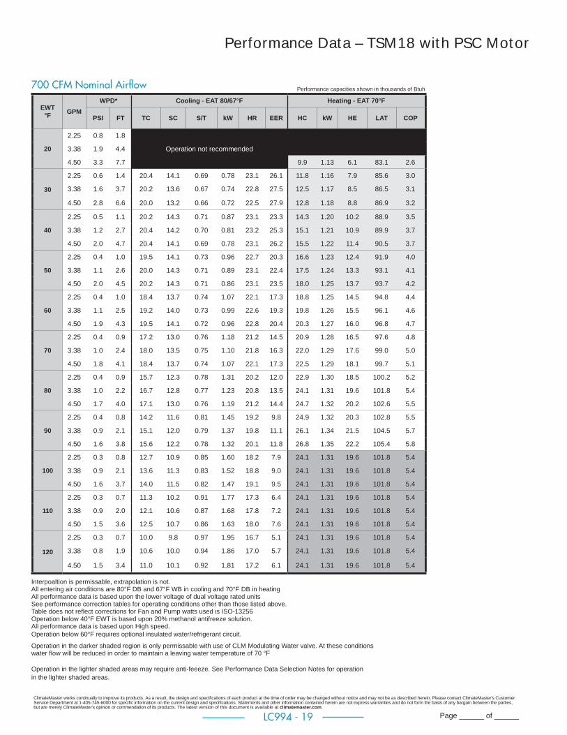
Performance Data – TSM18 with PSC Motor
Performance capacities shown in thousands of Btuh700 CFM Nominal Airfl ow
EWT °F GPM
WPD* Cooling - EAT 80/67°F Heating - EAT 70°F
PSI FT TC SC S/T kW HR EER HC kW HE LAT COP
20
2.25 0.8 1.8
Operation not recommended 3.38 1.9 4.4
4.50 3.3 7.7 9.9 1.13 6.1 83.1 2.6
30
2.25 0.6 1.4 20.4 14.1 0.69 0.78 23.1 26.1 11.8 1.16 7.9 85.6 3.0
3.38 1.6 3.7 20.2 13.6 0.67 0.74 22.8 27.5 12.5 1.17 8.5 86.5 3.1
4.50 2.8 6.6 20.0 13.2 0.66 0.72 22.5 27.9 12.8 1.18 8.8 86.9 3.2
40
2.25 0.5 1.1 20.2 14.3 0.71 0.87 23.1 23.3 14.3 1.20 10.2 88.9 3.5
3.38 1.2 2.7 20.4 14.2 0.70 0.81 23.2 25.3 15.1 1.21 10.9 89.9 3.7
4.50 2.0 4.7 20.4 14.1 0.69 0.78 23.1 26.2 15.5 1.22 11.4 90.5 3.7
50
2.25 0.4 1.0 19.5 14.1 0.73 0.96 22.7 20.3 16.6 1.23 12.4 91.9 4.0
3.38 1.1 2.6 20.0 14.3 0.71 0.89 23.1 22.4 17.5 1.24 13.3 93.1 4.1
4.50 2.0 4.5 20.2 14.3 0.71 0.86 23.1 23.5 18.0 1.25 13.7 93.7 4.2
60
2.25 0.4 1.0 18.4 13.7 0.74 1.07 22.1 17.3 18.8 1.25 14.5 94.8 4.4
3.38 1.1 2.5 19.2 14.0 0.73 0.99 22.6 19.3 19.8 1.26 15.5 96.1 4.6
4.50 1.9 4.3 19.5 14.1 0.72 0.96 22.8 20.4 20.3 1.27 16.0 96.8 4.7
70
2.25 0.4 0.9 17.2 13.0 0.76 1.18 21.2 14.5 20.9 1.28 16.5 97.6 4.8
3.38 1.0 2.4 18.0 13.5 0.75 1.10 21.8 16.3 22.0 1.29 17.6 99.0 5.0
4.50 1.8 4.1 18.4 13.7 0.74 1.07 22.1 17.3 22.5 1.29 18.1 99.7 5.1
80
2.25 0.4 0.9 15.7 12.3 0.78 1.31 20.2 12.0 22.9 1.30 18.5 100.2 5.2
3.38 1.0 2.2 16.7 12.8 0.77 1.23 20.8 13.5 24.1 1.31 19.6 101.8 5.4
4.50 1.7 4.0 17.1 13.0 0.76 1.19 21.2 14.4 24.7 1.32 20.2 102.6 5.5
90
2.25 0.4 0.8 14.2 11.6 0.81 1.45 19.2 9.8 24.9 1.32 20.3 102.8 5.5
3.38 0.9 2.1 15.1 12.0 0.79 1.37 19.8 11.1 26.1 1.34 21.5 104.5 5.7
4.50 1.6 3.8 15.6 12.2 0.78 1.32 20.1 11.8 26.8 1.35 22.2 105.4 5.8
100
2.25 0.3 0.8 12.7 10.9 0.85 1.60 18.2 7.9 24.1 1.31 19.6 101.8 5.4
3.38 0.9 2.1 13.6 11.3 0.83 1.52 18.8 9.0 24.1 1.31 19.6 101.8 5.4
4.50 1.6 3.7 14.0 11.5 0.82 1.47 19.1 9.5 24.1 1.31 19.6 101.8 5.4
110
2.25 0.3 0.7 11.3 10.2 0.91 1.77 17.3 6.4 24.1 1.31 19.6 101.8 5.4
3.38 0.9 2.0 12.1 10.6 0.87 1.68 17.8 7.2 24.1 1.31 19.6 101.8 5.4
4.50 1.5 3.6 12.5 10.7 0.86 1.63 18.0 7.6 24.1 1.31 19.6 101.8 5.4
120
2.25 0.3 0.7 10.0 9.8 0.97 1.95 16.7 5.1 24.1 1.31 19.6 101.8 5.4
3.38 0.8 1.9 10.6 10.0 0.94 1.86 17.0 5.7 24.1 1.31 19.6 101.8 5.4
4.50 1.5 3.4 11.0 10.1 0.92 1.81 17.2 6.1 24.1 1.31 19.6 101.8 5.4
Interpoaltion is permissable, extrapolation is not. All entering air conditions are 80°F DB and 67°F WB in cooling and 70°F DB in heating All performance data is based upon the lower voltage of dual voltage rated units See performance correction tables for operating conditions other than those listed above. Table does not refl ect corrections for Fan and Pump watts used is ISO-13256 Operation below 40°F EWT is based upon 20% methanol antifreeze solution. All performance data is based upon High speed.Operation below 60°F requires optional insulated water/refrigerant circuit. Operation in the darker shaded region is only permissable with use of CLM Modulating Water valve. At these conditions water fl ow will be reduced in order to maintain a leaving water temperature of 70 °F
Operation in the lighter shaded areas may require anti-feeeze. See Performance Data Selection Notes for operation in the lighter shaded areas.
ClimateMaster works continually to improve its products. As a result, the design and specifi cations of each product at the time of order may be changed without notice and may not be as described herein. Please contact ClimateMaster's Customer Service Department at 1-405-745-6000 for specifi c information on the current design and specifi cations. Statements and other information contained herein are not express warranties and do not form the basis of any bargain between the parties, but are merely ClimateMaster's opinion or commendation of its products. The latest version of this document is available at climatemaster.com.
Page ______ of ______LC994 - 20
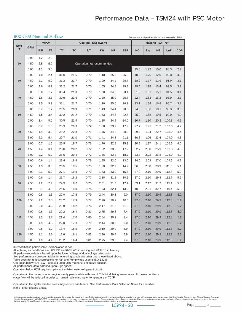
Performance Data – TSM24 with PSC Motor
Performance capacities shown in thousands of Btuh800 CFM Nominal Airfl ow
EWT °F GPM
WPD* Cooling - EAT 80/67°F Heating - EAT 70°F
PSI FT TC SC S/T kW HR EER HC kW HE LAT COP
20
3.00 1.2 2.8
Operation not recommended 4.50 2.5 5.9
6.00 4.1 9.6 15.8 1.72 10.0 88.3 2.7
30
3.00 1.0 2.4 31.0 21.6 0.70 1.18 35.0 26.3 18.0 1.76 12.0 90.8 3.0
4.50 2.1 5.0 31.2 21.7 0.70 1.09 34.9 28.7 18.9 1.77 12.9 91.9 3.1
6.00 3.6 8.2 31.2 21.7 0.70 1.05 34.8 29.8 19.5 1.78 13.4 92.5 3.2
40
3.00 0.8 1.7 30.4 21.3 0.70 1.30 34.8 23.4 21.2 1.81 15.1 94.5 3.4
4.50 1.6 3.6 30.9 21.6 0.70 1.20 35.0 25.7 22.4 1.83 16.2 95.9 3.6
6.00 2.5 5.9 31.1 21.7 0.70 1.16 35.0 26.9 23.1 1.84 16.8 96.7 3.7
50
3.00 0.7 1.7 29.5 20.9 0.71 1.43 34.4 20.6 24.5 1.86 18.1 98.3 3.9
4.50 1.5 3.4 30.2 21.2 0.70 1.33 34.8 22.8 25.9 1.88 19.5 99.9 4.0
6.00 2.4 5.6 30.5 21.4 0.70 1.28 34.9 24.0 26.7 1.90 20.2 100.8 4.1
60
3.00 0.7 1.6 28.3 20.3 0.72 1.58 33.7 17.9 27.7 1.91 21.2 102.0 4.2
4.50 1.4 3.3 29.2 20.8 0.71 1.46 34.2 20.0 29.3 1.94 22.7 103.9 4.4
6.00 2.3 5.4 29.7 21.0 0.71 1.41 34.5 21.1 30.3 1.96 23.6 104.9 4.5
70
3.00 0.7 1.5 26.9 19.7 0.73 1.76 32.9 15.3 30.9 1.97 24.1 105.6 4.6
4.50 1.4 3.1 28.0 20.2 0.72 1.62 33.5 17.2 32.7 2.00 25.9 107.8 4.8
6.00 2.2 5.2 28.5 20.4 0.72 1.56 33.8 18.3 33.7 2.02 26.8 108.9 4.9
80
3.00 0.6 1.4 25.4 18.9 0.75 1.95 32.0 13.0 34.0 2.03 27.0 109.2 4.9
4.50 1.3 3.0 26.5 19.5 0.73 1.80 32.7 14.7 36.0 2.08 28.9 111.5 5.1
6.00 2.1 5.0 27.1 19.8 0.73 1.73 33.0 15.6 37.0 2.10 29.9 112.8 5.2
90
3.00 0.6 1.4 23.7 18.2 0.77 2.18 31.2 10.9 37.0 2.10 29.8 112.7 5.2
4.50 1.2 2.9 24.9 18.7 0.75 2.01 31.8 12.4 39.1 2.17 31.7 115.1 5.3
6.00 2.1 4.8 25.5 19.0 0.75 1.93 32.1 13.2 40.2 2.21 32.7 116.4 5.3
100
3.00 0.6 1.3 22.0 17.3 0.79 2.44 30.3 9.0 37.0 2.10 29.9 112.8 5.2
4.50 1.2 2.8 23.2 17.9 0.77 2.26 30.9 10.3 37.0 2.10 29.9 112.8 5.2
6.00 2.0 4.6 23.8 18.2 0.76 2.17 31.2 11.0 37.0 2.10 29.9 112.8 5.2
110
3.00 0.6 1.3 20.2 16.4 0.81 2.75 29.6 7.4 37.0 2.10 29.9 112.8 5.2
4.50 1.2 2.7 21.4 17.0 0.80 2.54 30.1 8.4 37.0 2.10 29.9 112.8 5.2
6.00 1.9 4.5 22.0 17.3 0.79 2.44 30.3 9.0 37.0 2.10 29.9 112.8 5.2
120
3.00 0.5 1.2 18.4 15.5 0.84 3.10 29.0 5.9 37.0 2.10 29.9 112.8 5.2
4.50 1.1 2.6 19.6 16.1 0.82 2.86 29.4 6.9 37.0 2.10 29.9 112.8 5.2
6.00 1.9 4.4 20.2 16.4 0.81 2.75 29.6 7.4 37.0 2.10 29.9 112.8 5.2
Interpoaltion is permissable, extrapolation is not. All entering air conditions are 80°F DB and 67°F WB in cooling and 70°F DB in heating All performance data is based upon the lower voltage of dual voltage rated units See performance correction tables for operating conditions other than those listed above. Table does not refl ect corrections for Fan and Pump watts used is ISO-13256 Operation below 40°F EWT is based upon 20% methanol antifreeze solution. All performance data is based upon High speed.Operation below 60°F requires optional insulated water/refrigerant circuit. Operation in the darker shaded region is only permissable with use of CLM Modulating Water valve. At these conditions water fl ow will be reduced in order to maintain a leaving water temperature of 70 °F
Operation in the lighter shaded areas may require anti-feeeze. See Performance Data Selection Notes for operation in the lighter shaded areas.

ClimateMaster works continually to improve its products. As a result, the design and specifi cations of each product at the time of order may be changed without notice and may not be as described herein. Please contact ClimateMaster's Customer Service Department at 1-405-745-6000 for specifi c information on the current design and specifi cations. Statements and other information contained herein are not express warranties and do not form the basis of any bargain between the parties, but are merely ClimateMaster's opinion or commendation of its products. The latest version of this document is available at climatemaster.com.
Page ______ of ______LC994 - 21
Performance Data – TSM30 with PSC Motor
Performance capacities shown in thousands of Btuh1000 CFM Nominal Airfl ow
EWT °F GPM
WPD* Cooling - EAT 80/67°F Heating - EAT 70°F
PSI FT TC SC S/T kW HR EER HC kW HE LAT COP
20
3.75 1.5 3.5
Operation not recommended 5.63 3.3 7.5
7.50 5.4 12.6 18.1 1.90 11.6 86.7 2.8
30
3.75 1.3 3.1 33.7 23.5 0.70 1.31 38.1 25.8 20.4 1.91 13.9 88.8 3.1
5.63 2.9 6.6 33.3 22.8 0.69 1.23 37.5 27.1 21.3 1.92 14.8 89.7 3.3
7.50 5.0 11.6 33.0 22.4 0.68 1.19 37.1 27.6 21.8 1.92 15.3 90.2 3.3
40
3.75 1.0 2.3 33.6 23.7 0.71 1.43 38.4 23.5 23.8 1.94 17.1 92.0 3.6
5.63 2.1 4.9 33.7 23.6 0.70 1.34 38.3 25.2 24.9 1.95 18.3 93.0 3.7
7.50 3.5 8.0 33.7 23.4 0.70 1.30 38.1 25.9 25.5 1.96 18.9 93.6 3.8
50
3.75 1.0 2.2 32.9 23.4 0.71 1.56 38.2 21.0 27.1 1.97 20.4 95.0 4.0
5.63 2.0 4.7 33.4 23.7 0.71 1.47 38.4 22.8 28.4 1.99 21.6 96.2 4.2
7.50 3.4 7.9 33.6 23.7 0.71 1.42 38.4 23.7 29.1 2.00 22.3 96.9 4.3
60
3.75 0.9 2.1 31.7 22.8 0.72 1.72 37.5 18.4 30.4 2.02 23.5 98.0 4.4
5.63 2.0 4.5 32.5 23.3 0.72 1.61 38.0 20.2 31.9 2.04 24.9 99.4 4.6
7.50 3.3 7.7 32.9 23.5 0.71 1.56 38.2 21.1 32.7 2.05 25.7 100.2 4.7
70
3.75 0.9 2.0 30.1 21.9 0.73 1.89 36.6 15.9 33.6 2.07 26.5 101.0 4.8
5.63 1.9 4.4 31.2 22.5 0.72 1.77 37.2 17.6 35.3 2.10 28.1 102.6 4.9
7.50 3.2 7.5 31.7 22.8 0.72 1.71 37.5 18.5 36.2 2.12 29.0 103.4 5.0
80
3.75 0.9 2.0 28.3 20.9 0.74 2.10 35.4 13.5 36.8 2.13 29.5 104.0 5.1
5.63 1.8 4.2 29.5 21.6 0.73 1.96 36.2 15.0 38.7 2.17 31.3 105.7 5.2
7.50 3.2 7.3 30.1 21.9 0.73 1.90 36.6 15.9 39.7 2.20 32.2 106.7 5.3
90
3.75 0.8 1.9 26.2 19.9 0.76 2.33 34.2 11.2 40.0 2.20 32.5 106.9 5.3
5.63 1.8 4.1 27.5 20.5 0.75 2.18 35.0 12.6 42.0 2.26 34.3 108.8 5.5
7.50 3.1 7.1 28.2 20.9 0.74 2.11 35.4 13.4 43.1 2.29 35.3 109.8 5.5
100
3.75 0.8 1.8 24.1 18.9 0.78 2.60 33.0 9.2 38.7 2.17 31.3 105.7 5.2
5.63 1.7 3.9 25.4 19.5 0.77 2.43 33.7 10.4 38.7 2.17 31.3 105.7 5.2
7.50 3.0 6.8 26.1 19.8 0.76 2.35 34.1 11.1 38.7 2.17 31.3 105.7 5.2
110
3.75 0.8 1.8 21.9 17.9 0.82 2.92 31.8 7.5 38.7 2.17 31.3 105.7 5.2
5.63 1.7 3.8 23.2 18.5 0.80 2.73 32.5 8.5 38.7 2.17 31.3 105.7 5.2
7.50 2.8 6.6 23.8 18.8 0.79 2.64 32.8 9.0 38.7 2.17 31.3 105.7 5.2
120
3.75 0.7 1.7 19.7 17.1 0.87 3.27 30.9 6.0 38.7 2.17 31.3 105.7 5.2
5.63 1.6 3.7 20.9 17.6 0.84 3.07 31.4 6.8 38.7 2.17 31.3 105.7 5.2
7.50 2.7 6.3 21.6 17.8 0.83 2.96 31.7 7.3 38.7 2.17 31.3 105.7 5.2
Interpoaltion is permissable, extrapolation is not. All entering air conditions are 80°F DB and 67°F WB in cooling and 70°F DB in heating All performance data is based upon the lower voltage of dual voltage rated units See performance correction tables for operating conditions other than those listed above. Table does not refl ect corrections for Fan and Pump watts used is ISO-13256 Operation below 40°F EWT is based upon 20% methanol antifreeze solution. All performance data is based upon High speed.Operation below 60°F requires optional insulated water/refrigerant circuit. Operation in the darker shaded region is only permissable with use of CLM Modulating Water valve. At these conditions water fl ow will be reduced in order to maintain a leaving water temperature of 70 °F
Operation in the lighter shaded areas may require anti-feeeze. See Performance Data Selection Notes for operation in the lighter shaded areas.
ClimateMaster works continually to improve its products. As a result, the design and specifi cations of each product at the time of order may be changed without notice and may not be as described herein. Please contact ClimateMaster's Customer Service Department at 1-405-745-6000 for specifi c information on the current design and specifi cations. Statements and other information contained herein are not express warranties and do not form the basis of any bargain between the parties, but are merely ClimateMaster's opinion or commendation of its products. The latest version of this document is available at climatemaster.com.
Page ______ of ______LC994 - 22
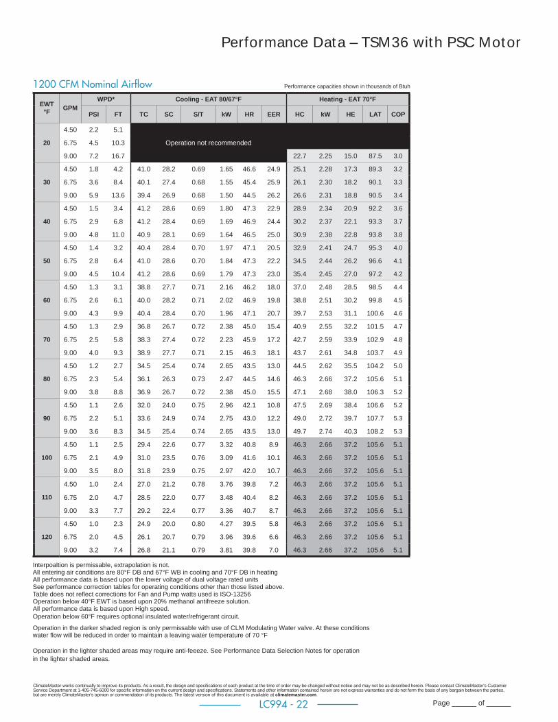
Performance Data – TSM36 with PSC Motor
Performance capacities shown in thousands of Btuh1200 CFM Nominal Airfl ow
EWT °F GPM
WPD* Cooling - EAT 80/67°F Heating - EAT 70°F
PSI FT TC SC S/T kW HR EER HC kW HE LAT COP
20
4.50 2.2 5.1
6.75 4.5 10.3 Operation not recommended
9.00 7.2 16.7 22.7 2.25 15.0 87.5 3.0
30
4.50 1.8 4.2 41.0 28.2 0.69 1.65 46.6 24.9 25.1 2.28 17.3 89.3 3.2
6.75 3.6 8.4 40.1 27.4 0.68 1.55 45.4 25.9 26.1 2.30 18.2 90.1 3.3
9.00 5.9 13.6 39.4 26.9 0.68 1.50 44.5 26.2 26.6 2.31 18.8 90.5 3.4
40
4.50 1.5 3.4 41.2 28.6 0.69 1.80 47.3 22.9 28.9 2.34 20.9 92.2 3.6
6.75 2.9 6.8 41.2 28.4 0.69 1.69 46.9 24.4 30.2 2.37 22.1 93.3 3.7
9.00 4.8 11.0 40.9 28.1 0.69 1.64 46.5 25.0 30.9 2.38 22.8 93.8 3.8
50
4.50 1.4 3.2 40.4 28.4 0.70 1.97 47.1 20.5 32.9 2.41 24.7 95.3 4.0
6.75 2.8 6.4 41.0 28.6 0.70 1.84 47.3 22.2 34.5 2.44 26.2 96.6 4.1
9.00 4.5 10.4 41.2 28.6 0.69 1.79 47.3 23.0 35.4 2.45 27.0 97.2 4.2
60
4.50 1.3 3.1 38.8 27.7 0.71 2.16 46.2 18.0 37.0 2.48 28.5 98.5 4.4
6.75 2.6 6.1 40.0 28.2 0.71 2.02 46.9 19.8 38.8 2.51 30.2 99.8 4.5
9.00 4.3 9.9 40.4 28.4 0.70 1.96 47.1 20.7 39.7 2.53 31.1 100.6 4.6
70
4.50 1.3 2.9 36.8 26.7 0.72 2.38 45.0 15.4 40.9 2.55 32.2 101.5 4.7
6.75 2.5 5.8 38.3 27.4 0.72 2.23 45.9 17.2 42.7 2.59 33.9 102.9 4.8
9.00 4.0 9.3 38.9 27.7 0.71 2.15 46.3 18.1 43.7 2.61 34.8 103.7 4.9
80
4.50 1.2 2.7 34.5 25.4 0.74 2.65 43.5 13.0 44.5 2.62 35.5 104.2 5.0
6.75 2.3 5.4 36.1 26.3 0.73 2.47 44.5 14.6 46.3 2.66 37.2 105.6 5.1
9.00 3.8 8.8 36.9 26.7 0.72 2.38 45.0 15.5 47.1 2.68 38.0 106.3 5.2
90
4.50 1.1 2.6 32.0 24.0 0.75 2.96 42.1 10.8 47.5 2.69 38.4 106.6 5.2
6.75 2.2 5.1 33.6 24.9 0.74 2.75 43.0 12.2 49.0 2.72 39.7 107.7 5.3
9.00 3.6 8.3 34.5 25.4 0.74 2.65 43.5 13.0 49.7 2.74 40.3 108.2 5.3
100
4.50 1.1 2.5 29.4 22.6 0.77 3.32 40.8 8.9 46.3 2.66 37.2 105.6 5.1
6.75 2.1 4.9 31.0 23.5 0.76 3.09 41.6 10.1 46.3 2.66 37.2 105.6 5.1
9.00 3.5 8.0 31.8 23.9 0.75 2.97 42.0 10.7 46.3 2.66 37.2 105.6 5.1
110
4.50 1.0 2.4 27.0 21.2 0.78 3.76 39.8 7.2 46.3 2.66 37.2 105.6 5.1
6.75 2.0 4.7 28.5 22.0 0.77 3.48 40.4 8.2 46.3 2.66 37.2 105.6 5.1
9.00 3.3 7.7 29.2 22.4 0.77 3.36 40.7 8.7 46.3 2.66 37.2 105.6 5.1
120
4.50 1.0 2.3 24.9 20.0 0.80 4.27 39.5 5.8 46.3 2.66 37.2 105.6 5.1
6.75 2.0 4.5 26.1 20.7 0.79 3.96 39.6 6.6 46.3 2.66 37.2 105.6 5.1
9.00 3.2 7.4 26.8 21.1 0.79 3.81 39.8 7.0 46.3 2.66 37.2 105.6 5.1
Interpoaltion is permissable, extrapolation is not. All entering air conditions are 80°F DB and 67°F WB in cooling and 70°F DB in heating All performance data is based upon the lower voltage of dual voltage rated units See performance correction tables for operating conditions other than those listed above. Table does not refl ect corrections for Fan and Pump watts used is ISO-13256 Operation below 40°F EWT is based upon 20% methanol antifreeze solution. All performance data is based upon High speed.Operation below 60°F requires optional insulated water/refrigerant circuit. Operation in the darker shaded region is only permissable with use of CLM Modulating Water valve. At these conditions water fl ow will be reduced in order to maintain a leaving water temperature of 70 °F
Operation in the lighter shaded areas may require anti-feeeze. See Performance Data Selection Notes for operation in the lighter shaded areas.
ClimateMaster works continually to improve its products. As a result, the design and specifi cations of each product at the time of order may be changed without notice and may not be as described herein. Please contact ClimateMaster's Customer Service Department at 1-405-745-6000 for specifi c information on the current design and specifi cations. Statements and other information contained herein are not express warranties and do not form the basis of any bargain between the parties, but are merely ClimateMaster's opinion or commendation of its products. The latest version of this document is available at climatemaster.com.
Page ______ of ______LC994 - 23
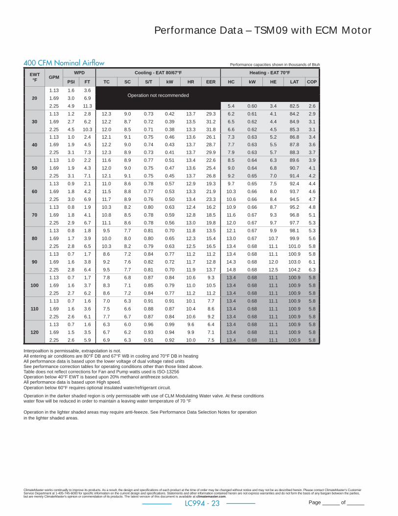
Performance Data – TSM09 with ECM Motor
EWT °F GPM
WPD Cooling - EAT 80/67°F Heating - EAT 70°F
PSI FT TC SC S/T kW HR EER HC kW HE LAT COP
201.13 1.6 3.6
Operation not recommended 1.69 3.0 6.92.25 4.9 11.3 5.4 0.60 3.4 82.5 2.6
301.13 1.2 2.8 12.3 9.0 0.73 0.42 13.7 29.3 6.2 0.61 4.1 84.2 2.91.69 2.7 6.2 12.2 8.7 0.72 0.39 13.5 31.2 6.5 0.62 4.4 84.9 3.12.25 4.5 10.3 12.0 8.5 0.71 0.38 13.3 31.8 6.6 0.62 4.5 85.3 3.1
401.13 1.0 2.4 12.1 9.1 0.75 0.46 13.6 26.1 7.3 0.63 5.2 86.8 3.41.69 1.9 4.5 12.2 9.0 0.74 0.43 13.7 28.7 7.7 0.63 5.5 87.8 3.62.25 3.1 7.3 12.3 8.9 0.73 0.41 13.7 29.9 7.9 0.63 5.7 88.3 3.7
501.13 1.0 2.2 11.6 8.9 0.77 0.51 13.4 22.6 8.5 0.64 6.3 89.6 3.91.69 1.9 4.3 12.0 9.0 0.75 0.47 13.6 25.4 9.0 0.64 6.8 90.7 4.12.25 3.1 7.1 12.1 9.1 0.75 0.45 13.7 26.8 9.2 0.65 7.0 91.4 4.2
601.13 0.9 2.1 11.0 8.6 0.78 0.57 12.9 19.3 9.7 0.65 7.5 92.4 4.41.69 1.8 4.2 11.5 8.8 0.77 0.53 13.3 21.9 10.3 0.66 8.0 93.7 4.62.25 3.0 6.9 11.7 8.9 0.76 0.50 13.4 23.3 10.6 0.66 8.4 94.5 4.7
701.13 0.8 1.9 10.3 8.2 0.80 0.63 12.4 16.2 10.9 0.66 8.7 95.2 4.81.69 1.8 4.1 10.8 8.5 0.78 0.59 12.8 18.5 11.6 0.67 9.3 96.8 5.12.25 2.9 6.7 11.1 8.6 0.78 0.56 13.0 19.8 12.0 0.67 9.7 97.7 5.3
801.13 0.8 1.8 9.5 7.7 0.81 0.70 11.8 13.5 12.1 0.67 9.9 98.1 5.31.69 1.7 3.9 10.0 8.0 0.80 0.65 12.3 15.4 13.0 0.67 10.7 99.9 5.62.25 2.8 6.5 10.3 8.2 0.79 0.63 12.5 16.5 13.4 0.68 11.1 101.0 5.8
901.13 0.7 1.7 8.6 7.2 0.84 0.77 11.2 11.2 13.4 0.68 11.1 100.9 5.81.69 1.6 3.8 9.2 7.6 0.82 0.72 11.7 12.8 14.3 0.68 12.0 103.0 6.12.25 2.8 6.4 9.5 7.7 0.81 0.70 11.9 13.7 14.8 0.68 12.5 104.2 6.3
1001.13 0.7 1.7 7.8 6.8 0.87 0.84 10.6 9.3 13.4 0.68 11.1 100.9 5.81.69 1.6 3.7 8.3 7.1 0.85 0.79 11.0 10.5 13.4 0.68 11.1 100.9 5.82.25 2.7 6.2 8.6 7.2 0.84 0.77 11.2 11.2 13.4 0.68 11.1 100.9 5.8
1101.13 0.7 1.6 7.0 6.3 0.91 0.91 10.1 7.7 13.4 0.68 11.1 100.9 5.81.69 1.6 3.6 7.5 6.6 0.88 0.87 10.4 8.6 13.4 0.68 11.1 100.9 5.82.25 2.6 6.1 7.7 6.7 0.87 0.84 10.6 9.2 13.4 0.68 11.1 100.9 5.8
1201.13 0.7 1.6 6.3 6.0 0.96 0.99 9.6 6.4 13.4 0.68 11.1 100.9 5.81.69 1.5 3.5 6.7 6.2 0.93 0.94 9.9 7.1 13.4 0.68 11.1 100.9 5.82.25 2.6 5.9 6.9 6.3 0.91 0.92 10.0 7.5 13.4 0.68 11.1 100.9 5.8
Performance capacities shown in thousands of Btuh400 CFM Nominal Airfl ow
Interpoaltion is permissable, extrapolation is not. All entering air conditions are 80°F DB and 67°F WB in cooling and 70°F DB in heating All performance data is based upon the lower voltage of dual voltage rated units See performance correction tables for operating conditions other than those listed above. Table does not refl ect corrections for Fan and Pump watts used is ISO-13256 Operation below 40°F EWT is based upon 20% methanol antifreeze solution. All performance data is based upon High speed.Operation below 60°F requires optional insulated water/refrigerant circuit. Operation in the darker shaded region is only permissable with use of CLM Modulating Water valve. At these conditions water fl ow will be reduced in order to maintain a leaving water temperature of 70 °F
Operation in the lighter shaded areas may require anti-feeeze. See Performance Data Selection Notes for operation in the lighter shaded areas.
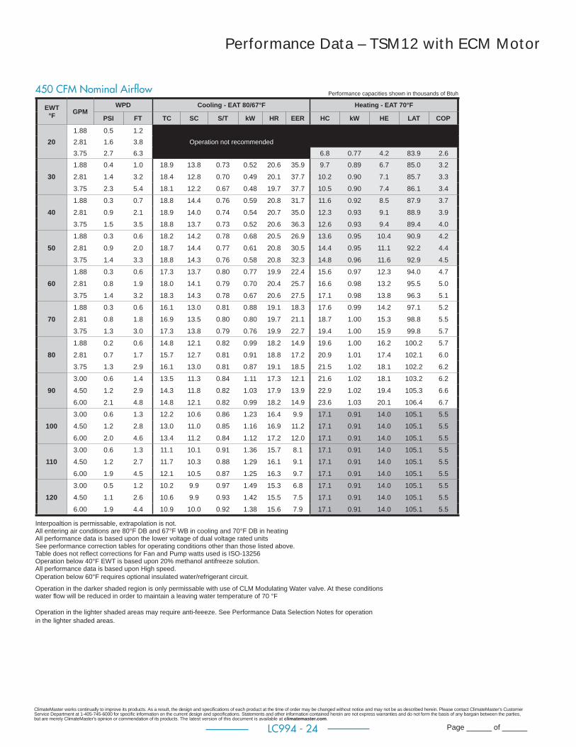
ClimateMaster works continually to improve its products. As a result, the design and specifi cations of each product at the time of order may be changed without notice and may not be as described herein. Please contact ClimateMaster's Customer Service Department at 1-405-745-6000 for specifi c information on the current design and specifi cations. Statements and other information contained herein are not express warranties and do not form the basis of any bargain between the parties, but are merely ClimateMaster's opinion or commendation of its products. The latest version of this document is available at climatemaster.com.
Page ______ of ______LC994 - 24
Performance Data – TSM12 with ECM Motor
EWT °F GPM
WPD Cooling - EAT 80/67°F Heating - EAT 70°F
PSI FT TC SC S/T kW HR EER HC kW HE LAT COP
201.88 0.5 1.2
Operation not recommended2.81 1.6 3.83.75 2.7 6.3 6.8 0.77 4.2 83.9 2.61.88 0.4 1.0 18.9 13.8 0.73 0.52 20.6 35.9 9.7 0.89 6.7 85.0 3.2
30 2.81 1.4 3.2 18.4 12.8 0.70 0.49 20.1 37.7 10.2 0.90 7.1 85.7 3.3
3.75 2.3 5.4 18.1 12.2 0.67 0.48 19.7 37.7 10.5 0.90 7.4 86.1 3.4
1.88 0.3 0.7 18.8 14.4 0.76 0.59 20.8 31.7 11.6 0.92 8.5 87.9 3.7
40 2.81 0.9 2.1 18.9 14.0 0.74 0.54 20.7 35.0 12.3 0.93 9.1 88.9 3.9
3.75 1.5 3.5 18.8 13.7 0.73 0.52 20.6 36.3 12.6 0.93 9.4 89.4 4.0
1.88 0.3 0.6 18.2 14.2 0.78 0.68 20.5 26.9 13.6 0.95 10.4 90.9 4.2
50 2.81 0.9 2.0 18.7 14.4 0.77 0.61 20.8 30.5 14.4 0.95 11.1 92.2 4.4
3.75 1.4 3.3 18.8 14.3 0.76 0.58 20.8 32.3 14.8 0.96 11.6 92.9 4.5
1.88 0.3 0.6 17.3 13.7 0.80 0.77 19.9 22.4 15.6 0.97 12.3 94.0 4.7
60 2.81 0.8 1.9 18.0 14.1 0.79 0.70 20.4 25.7 16.6 0.98 13.2 95.5 5.0
3.75 1.4 3.2 18.3 14.3 0.78 0.67 20.6 27.5 17.1 0.98 13.8 96.3 5.1
1.88 0.3 0.6 16.1 13.0 0.81 0.88 19.1 18.3 17.6 0.99 14.2 97.1 5.2
70 2.81 0.8 1.8 16.9 13.5 0.80 0.80 19.7 21.1 18.7 1.00 15.3 98.8 5.5
3.75 1.3 3.0 17.3 13.8 0.79 0.76 19.9 22.7 19.4 1.00 15.9 99.8 5.7
1.88 0.2 0.6 14.8 12.1 0.82 0.99 18.2 14.9 19.6 1.00 16.2 100.2 5.7
80 2.81 0.7 1.7 15.7 12.7 0.81 0.91 18.8 17.2 20.9 1.01 17.4 102.1 6.0
3.75 1.3 2.9 16.1 13.0 0.81 0.87 19.1 18.5 21.5 1.02 18.1 102.2 6.2
3.00 0.6 1.4 13.5 11.3 0.84 1.11 17.3 12.1 21.6 1.02 18.1 103.2 6.2
90 4.50 1.2 2.9 14.3 11.8 0.82 1.03 17.9 13.9 22.9 1.02 19.4 105.3 6.6
6.00 2.1 4.8 14.8 12.1 0.82 0.99 18.2 14.9 23.6 1.03 20.1 106.4 6.7
3.00 0.6 1.3 12.2 10.6 0.86 1.23 16.4 9.9 17.1 0.91 14.0 105.1 5.5
100 4.50 1.2 2.8 13.0 11.0 0.85 1.16 16.9 11.2 17.1 0.91 14.0 105.1 5.5
6.00 2.0 4.6 13.4 11.2 0.84 1.12 17.2 12.0 17.1 0.91 14.0 105.1 5.5
3.00 0.6 1.3 11.1 10.1 0.91 1.36 15.7 8.1 17.1 0.91 14.0 105.1 5.5
110 4.50 1.2 2.7 11.7 10.3 0.88 1.29 16.1 9.1 17.1 0.91 14.0 105.1 5.5
6.00 1.9 4.5 12.1 10.5 0.87 1.25 16.3 9.7 17.1 0.91 14.0 105.1 5.5
3.00 0.5 1.2 10.2 9.9 0.97 1.49 15.3 6.8 17.1 0.91 14.0 105.1 5.5
120 4.50 1.1 2.6 10.6 9.9 0.93 1.42 15.5 7.5 17.1 0.91 14.0 105.1 5.5
6.00 1.9 4.4 10.9 10.0 0.92 1.38 15.6 7.9 17.1 0.91 14.0 105.1 5.5
Performance capacities shown in thousands of Btuh450 CFM Nominal Airfl ow
Interpoaltion is permissable, extrapolation is not. All entering air conditions are 80°F DB and 67°F WB in cooling and 70°F DB in heating All performance data is based upon the lower voltage of dual voltage rated units See performance correction tables for operating conditions other than those listed above. Table does not refl ect corrections for Fan and Pump watts used is ISO-13256 Operation below 40°F EWT is based upon 20% methanol antifreeze solution. All performance data is based upon High speed.Operation below 60°F requires optional insulated water/refrigerant circuit. Operation in the darker shaded region is only permissable with use of CLM Modulating Water valve. At these conditions water fl ow will be reduced in order to maintain a leaving water temperature of 70 °F
Operation in the lighter shaded areas may require anti-feeeze. See Performance Data Selection Notes for operation in the lighter shaded areas.
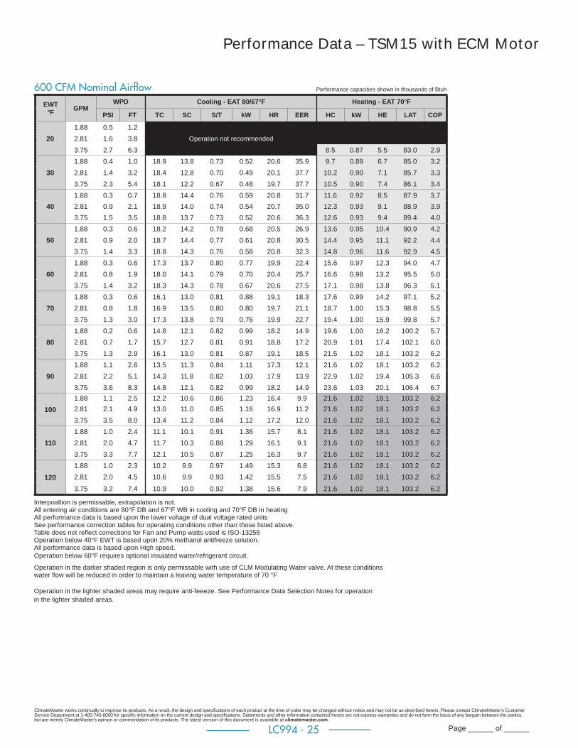
ClimateMaster works continually to improve its products. As a result, the design and specifi cations of each product at the time of order may be changed without notice and may not be as described herein. Please contact ClimateMaster's Customer Service Department at 1-405-745-6000 for specifi c information on the current design and specifi cations. Statements and other information contained herein are not express warranties and do not form the basis of any bargain between the parties, but are merely ClimateMaster's opinion or commendation of its products. The latest version of this document is available at climatemaster.com.
Page ______ of ______LC994 - 25
Performance Data – TSM15 with ECM Motor
Performance capacities shown in thousands of Btuh600 CFM Nominal Airfl owEWT
°F GPMWPD Cooling - EAT 80/67°F Heating - EAT 70°F
PSI FT TC SC S/T kW HR EER HC kW HE LAT COP
201.88 0.5 1.22.81 1.6 3.8 Operation not recommended
3.75 2.7 6.3 8.5 0.87 5.5 83.0 2.9
301.88 0.4 1.0 18.9 13.8 0.73 0.52 20.6 35.9 9.7 0.89 6.7 85.0 3.22.81 1.4 3.2 18.4 12.8 0.70 0.49 20.1 37.7 10.2 0.90 7.1 85.7 3.33.75 2.3 5.4 18.1 12.2 0.67 0.48 19.7 37.7 10.5 0.90 7.4 86.1 3.4
401.88 0.3 0.7 18.8 14.4 0.76 0.59 20.8 31.7 11.6 0.92 8.5 87.9 3.72.81 0.9 2.1 18.9 14.0 0.74 0.54 20.7 35.0 12.3 0.93 9.1 88.9 3.93.75 1.5 3.5 18.8 13.7 0.73 0.52 20.6 36.3 12.6 0.93 9.4 89.4 4.0
501.88 0.3 0.6 18.2 14.2 0.78 0.68 20.5 26.9 13.6 0.95 10.4 90.9 4.22.81 0.9 2.0 18.7 14.4 0.77 0.61 20.8 30.5 14.4 0.95 11.1 92.2 4.43.75 1.4 3.3 18.8 14.3 0.76 0.58 20.8 32.3 14.8 0.96 11.6 92.9 4.5
601.88 0.3 0.6 17.3 13.7 0.80 0.77 19.9 22.4 15.6 0.97 12.3 94.0 4.72.81 0.8 1.9 18.0 14.1 0.79 0.70 20.4 25.7 16.6 0.98 13.2 95.5 5.03.75 1.4 3.2 18.3 14.3 0.78 0.67 20.6 27.5 17.1 0.98 13.8 96.3 5.1
701.88 0.3 0.6 16.1 13.0 0.81 0.88 19.1 18.3 17.6 0.99 14.2 97.1 5.22.81 0.8 1.8 16.9 13.5 0.80 0.80 19.7 21.1 18.7 1.00 15.3 98.8 5.53.75 1.3 3.0 17.3 13.8 0.79 0.76 19.9 22.7 19.4 1.00 15.9 99.8 5.7
801.88 0.2 0.6 14.8 12.1 0.82 0.99 18.2 14.9 19.6 1.00 16.2 100.2 5.72.81 0.7 1.7 15.7 12.7 0.81 0.91 18.8 17.2 20.9 1.01 17.4 102.1 6.03.75 1.3 2.9 16.1 13.0 0.81 0.87 19.1 18.5 21.5 1.02 18.1 103.2 6.2
901.88 1.1 2.6 13.5 11.3 0.84 1.11 17.3 12.1 21.6 1.02 18.1 103.2 6.22.81 2.2 5.1 14.3 11.8 0.82 1.03 17.9 13.9 22.9 1.02 19.4 105.3 6.63.75 3.6 8.3 14.8 12.1 0.82 0.99 18.2 14.9 23.6 1.03 20.1 106.4 6.7
1001.88 1.1 2.5 12.2 10.6 0.86 1.23 16.4 9.9 21.6 1.02 18.1 103.2 6.22.81 2.1 4.9 13.0 11.0 0.85 1.16 16.9 11.2 21.6 1.02 18.1 103.2 6.23.75 3.5 8.0 13.4 11.2 0.84 1.12 17.2 12.0 21.6 1.02 18.1 103.2 6.2
1101.88 1.0 2.4 11.1 10.1 0.91 1.36 15.7 8.1 21.6 1.02 18.1 103.2 6.22.81 2.0 4.7 11.7 10.3 0.88 1.29 16.1 9.1 21.6 1.02 18.1 103.2 6.23.75 3.3 7.7 12.1 10.5 0.87 1.25 16.3 9.7 21.6 1.02 18.1 103.2 6.2
1201.88 1.0 2.3 10.2 9.9 0.97 1.49 15.3 6.8 21.6 1.02 18.1 103.2 6.22.81 2.0 4.5 10.6 9.9 0.93 1.42 15.5 7.5 21.6 1.02 18.1 103.2 6.2
3.75 3.2 7.4 10.9 10.0 0.92 1.38 15.6 7.9 21.6 1.02 18.1 103.2 6.2
Interpoaltion is permissable, extrapolation is not. All entering air conditions are 80°F DB and 67°F WB in cooling and 70°F DB in heating All performance data is based upon the lower voltage of dual voltage rated units See performance correction tables for operating conditions other than those listed above. Table does not refl ect corrections for Fan and Pump watts used is ISO-13256 Operation below 40°F EWT is based upon 20% methanol antifreeze solution. All performance data is based upon High speed.Operation below 60°F requires optional insulated water/refrigerant circuit. Operation in the darker shaded region is only permissable with use of CLM Modulating Water valve. At these conditions water fl ow will be reduced in order to maintain a leaving water temperature of 70 °F
Operation in the lighter shaded areas may require anti-feeeze. See Performance Data Selection Notes for operation in the lighter shaded areas.

ClimateMaster works continually to improve its products. As a result, the design and specifi cations of each product at the time of order may be changed without notice and may not be as described herein. Please contact ClimateMaster's Customer Service Department at 1-405-745-6000 for specifi c information on the current design and specifi cations. Statements and other information contained herein are not express warranties and do not form the basis of any bargain between the parties, but are merely ClimateMaster's opinion or commendation of its products. The latest version of this document is available at climatemaster.com.
Page ______ of ______LC994 - 26
Performance Data – TSM18 with ECM Motor
EWT °F GPM
WPD Cooling - EAT 80/67°F Heating - EAT 70°F
PSI FT TC SC S/T kW HR EER HC kW HE LAT COP
202.25 0.8 1.8
Operation not recommended3.38 1.9 4.44.50 3.3 7.7 9.3 1.05 5.7 82.2 2.6
302.25 0.6 1.4 20.4 14.1 0.69 0.70 22.8 29.1 11.1 1.08 7.4 84.7 3.03.38 1.6 3.7 20.2 13.6 0.67 0.66 22.5 30.8 11.7 1.09 8.0 85.4 3.14.50 2.8 6.6 20.0 13.2 0.66 0.64 22.2 31.4 12.0 1.10 8.3 85.9 3.2
402.25 0.5 1.1 20.2 14.3 0.71 0.78 22.9 25.8 13.5 1.12 9.6 87.8 3.53.38 1.2 2.7 20.4 14.2 0.70 0.73 22.9 28.1 14.2 1.13 10.3 88.7 3.74.50 2.0 4.7 20.4 14.1 0.69 0.70 22.8 29.2 14.6 1.14 10.7 89.2 3.8
502.25 0.4 1.0 19.5 14.1 0.72 0.88 22.5 22.2 15.7 1.15 11.8 90.7 4.03.38 1.1 2.6 20.0 14.3 0.71 0.81 22.8 24.7 16.5 1.16 12.5 91.8 4.24.50 2.0 4.5 20.2 14.3 0.71 0.78 22.9 25.9 16.9 1.17 12.9 92.3 4.3
602.25 0.4 1.0 18.5 13.7 0.74 0.98 21.8 18.8 17.8 1.18 13.8 93.5 4.43.38 1.1 2.5 19.2 14.0 0.73 0.91 22.3 21.1 18.7 1.19 14.6 94.6 4.64.50 1.9 4.3 19.5 14.1 0.72 0.88 22.5 22.3 19.1 1.19 15.1 95.3 4.7
702.25 0.4 0.9 17.2 13.0 0.76 1.10 21.0 15.6 19.8 1.20 15.7 96.1 4.83.38 1.0 2.4 18.0 13.5 0.75 1.02 21.5 17.6 20.7 1.21 16.6 97.4 5.04.50 1.8 4.1 18.5 13.7 0.74 0.98 21.8 18.7 21.3 1.22 17.1 98.1 5.1
802.25 0.4 0.9 15.8 12.3 0.78 1.23 20.0 12.8 21.7 1.22 17.5 98.6 5.23.38 1.0 2.2 16.7 12.8 0.77 1.15 20.6 14.5 22.7 1.23 18.5 100.0 5.44.50 1.7 4.0 17.1 13.0 0.76 1.11 20.9 15.5 23.3 1.24 19.1 100.8 5.5
902.25 0.4 0.8 14.3 11.6 0.81 1.37 19.0 10.4 23.6 1.25 19.3 101.1 5.53.38 0.9 2.1 15.2 12.0 0.79 1.29 19.6 11.8 24.7 1.27 20.4 102.6 5.74.50 1.6 3.8 15.6 12.3 0.78 1.24 19.9 12.6 25.4 1.28 21.0 103.5 5.8
1002.25 0.3 0.8 12.8 10.9 0.85 1.52 18.0 8.4 22.7 1.23 18.5 100.0 5.43.38 0.9 2.1 13.6 11.3 0.83 1.44 18.5 9.5 22.7 1.23 18.5 100.0 5.44.50 1.6 3.7 14.1 11.5 0.82 1.39 18.8 10.1 22.7 1.23 18.5 100.0 5.4
1102.25 0.3 0.7 11.3 10.2 0.90 1.69 17.1 6.7 22.7 1.23 18.5 100.0 5.43.38 0.9 2.0 12.1 10.6 0.87 1.60 17.5 7.6 22.7 1.23 18.5 100.0 5.44.50 1.5 3.6 12.5 10.7 0.86 1.55 17.8 8.0 22.7 1.23 18.5 100.0 5.4
1202.25 0.3 0.7 10.0 9.8 0.97 1.86 16.4 5.4 22.7 1.23 18.5 100.0 5.43.38 0.8 1.9 10.7 10.0 0.94 1.77 16.7 6.0 22.7 1.23 18.5 100.0 5.44.50 1.5 3.4 11.0 10.1 0.92 1.73 16.9 6.4 22.7 1.23 18.5 100.0 5.4
Performance capacities shown in thousands of Btuh700 CFM Nominal Airfl ow
Interpoaltion is permissable, extrapolation is not. All entering air conditions are 80°F DB and 67°F WB in cooling and 70°F DB in heating All performance data is based upon the lower voltage of dual voltage rated units See performance correction tables for operating conditions other than those listed above. Table does not refl ect corrections for Fan and Pump watts used is ISO-13256 Operation below 40°F EWT is based upon 20% methanol antifreeze solution. All performance data is based upon High speed.Operation below 60°F requires optional insulated water/refrigerant circuit. Operation in the darker shaded region is only permissable with use of CLM Modulating Water valve. At these conditions water fl ow will be reduced in order to maintain a leaving water temperature of 70 °F
Operation in the lighter shaded areas may require anti-feeeze. See Performance Data Selection Notes for operation in the lighter shaded areas.

ClimateMaster works continually to improve its products. As a result, the design and specifi cations of each product at the time of order may be changed without notice and may not be as described herein. Please contact ClimateMaster's Customer Service Department at 1-405-745-6000 for specifi c information on the current design and specifi cations. Statements and other information contained herein are not express warranties and do not form the basis of any bargain between the parties, but are merely ClimateMaster's opinion or commendation of its products. The latest version of this document is available at climatemaster.com.
Page ______ of ______LC994 - 27
Performance Data – TSM24 with ECM Motor
EWT °F GPM
WPD Cooling - EAT 80/67°F Heating - EAT 70°F
PSI FT TC SC S/T kW HR EER HC kW HE LAT COP
203.00 1.2 2.8
Operation not recommended4.50 2.5 5.96.00 4.1 9.6 15.0 1.62 9.4 87.3 2.7
303.00 1.0 2.4 31.0 21.6 0.70 1.08 34.7 28.8 17.1 1.66 11.5 89.8 3.04.50 2.1 5.0 31.2 21.7 0.70 0.99 34.6 31.6 18.0 1.68 12.3 90.8 3.26.00 3.6 8.2 31.2 21.7 0.70 0.95 34.4 33.0 18.6 1.69 12.8 91.4 3.2
403.00 0.8 1.7 30.4 21.3 0.70 1.20 34.5 25.4 20.4 1.71 14.5 93.5 3.54.50 1.6 3.6 30.9 21.6 0.70 1.10 34.7 28.1 21.5 1.73 15.6 94.8 3.66.00 2.5 5.9 31.1 21.7 0.70 1.06 34.7 29.4 22.1 1.74 16.2 95.6 3.7
503.00 0.7 1.7 29.5 20.9 0.71 1.33 34.0 22.2 23.6 1.77 17.5 97.2 3.94.50 1.5 3.4 30.3 21.2 0.70 1.22 34.4 24.7 24.9 1.79 18.8 98.8 4.16.00 2.4 5.6 30.6 21.4 0.70 1.17 34.6 26.0 25.7 1.80 19.6 99.7 4.2
603.00 0.7 1.6 28.3 20.3 0.72 1.48 33.4 19.1 26.8 1.82 20.6 100.9 4.34.50 1.4 3.3 29.3 20.8 0.71 1.36 33.9 21.5 28.3 1.84 22.1 102.7 4.56.00 2.3 5.4 29.7 21.0 0.71 1.31 34.1 22.7 29.2 1.86 22.9 103.7 4.6
703.00 0.7 1.5 26.9 19.7 0.73 1.65 32.6 16.3 29.9 1.87 23.5 104.5 4.74.50 1.4 3.1 28.0 20.2 0.72 1.52 33.2 18.4 31.7 1.91 25.2 106.6 4.96.00 2.2 5.2 28.5 20.4 0.72 1.46 33.5 19.5 32.7 1.93 26.1 107.7 5.0
803.00 0.6 1.4 25.4 19.0 0.75 1.85 31.7 13.7 33.0 1.93 26.4 108.1 5.04.50 1.3 3.0 26.6 19.5 0.73 1.70 32.4 15.6 34.9 1.98 28.2 110.3 5.26.00 2.1 5.0 27.1 19.8 0.73 1.63 32.7 16.6 36.0 2.01 29.1 111.6 5.3
903.00 0.6 1.4 23.7 18.2 0.77 2.08 30.8 11.4 36.0 2.01 29.1 111.5 5.34.50 1.2 2.9 24.9 18.7 0.75 1.91 31.5 13.0 38.1 2.07 31.0 113.9 5.46.00 2.1 4.8 25.5 19.0 0.74 1.83 31.8 13.9 39.2 2.11 32.0 115.2 5.4
1003.00 0.6 1.3 22.0 17.3 0.79 2.34 30.0 9.4 36.0 2.01 29.1 111.6 5.34.50 1.2 2.8 23.2 17.9 0.77 2.15 30.6 10.8 36.0 2.01 29.1 111.6 5.36.00 2.0 4.6 23.8 18.2 0.76 2.07 30.9 11.5 36.0 2.01 29.1 111.6 5.3
1103.00 0.6 1.3 20.2 16.5 0.81 2.64 29.3 7.7 36.0 2.01 29.1 111.6 5.34.50 1.2 2.7 21.4 17.1 0.80 2.43 29.7 8.8 36.0 2.01 29.1 111.6 5.36.00 1.9 4.5 22.0 17.4 0.79 2.33 30.0 9.4 36.0 2.01 29.1 111.6 5.3
1203.00 0.5 1.2 18.5 15.6 0.84 2.99 28.7 6.2 36.0 2.01 29.1 111.6 5.34.50 1.1 2.6 19.6 16.2 0.82 2.76 29.0 7.1 36.0 2.01 29.1 111.6 5.36.00 1.9 4.4 20.2 16.5 0.81 2.65 29.3 7.6 36.0 2.01 29.1 111.6 5.3
Performance capacities shown in thousands of Btuh850 CFM Nominal Airfl ow
Interpoaltion is permissable, extrapolation is not. All entering air conditions are 80°F DB and 67°F WB in cooling and 70°F DB in heating All performance data is based upon the lower voltage of dual voltage rated units See performance correction tables for operating conditions other than those listed above. Table does not refl ect corrections for Fan and Pump watts used is ISO-13256 Operation below 40°F EWT is based upon 20% methanol antifreeze solution. All performance data is based upon High speed.Operation below 60°F requires optional insulated water/refrigerant circuit. Operation in the darker shaded region is only permissable with use of CLM Modulating Water valve. At these conditions water fl ow will be reduced in order to maintain a leaving water temperature of 70 °F
Operation in the lighter shaded areas may require anti-feeeze. See Performance Data Selection Notes for operation in the lighter shaded areas.
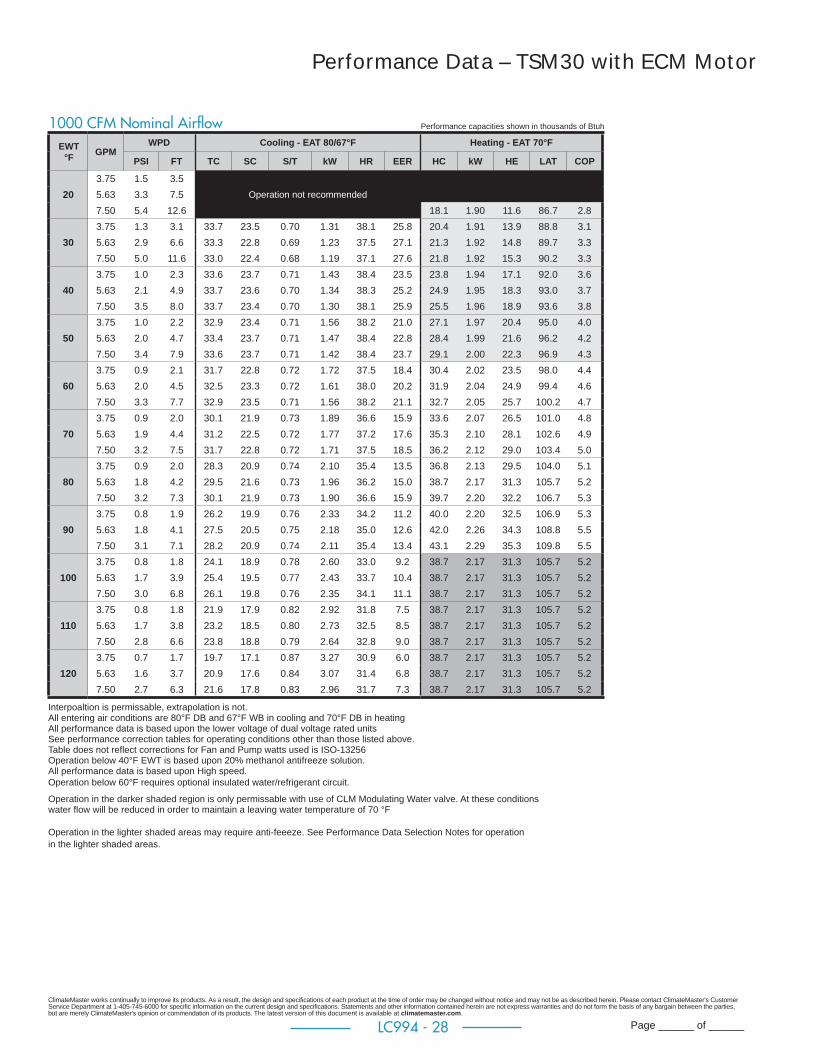
ClimateMaster works continually to improve its products. As a result, the design and specifi cations of each product at the time of order may be changed without notice and may not be as described herein. Please contact ClimateMaster's Customer Service Department at 1-405-745-6000 for specifi c information on the current design and specifi cations. Statements and other information contained herein are not express warranties and do not form the basis of any bargain between the parties, but are merely ClimateMaster's opinion or commendation of its products. The latest version of this document is available at climatemaster.com.
Page ______ of ______LC994 - 28
Performance Data – TSM30 with ECM Motor
EWT °F GPM
WPD Cooling - EAT 80/67°F Heating - EAT 70°F
PSI FT TC SC S/T kW HR EER HC kW HE LAT COP
203.75 1.5 3.5
Operation not recommended5.63 3.3 7.57.50 5.4 12.6 18.1 1.90 11.6 86.7 2.8
303.75 1.3 3.1 33.7 23.5 0.70 1.31 38.1 25.8 20.4 1.91 13.9 88.8 3.15.63 2.9 6.6 33.3 22.8 0.69 1.23 37.5 27.1 21.3 1.92 14.8 89.7 3.37.50 5.0 11.6 33.0 22.4 0.68 1.19 37.1 27.6 21.8 1.92 15.3 90.2 3.3
403.75 1.0 2.3 33.6 23.7 0.71 1.43 38.4 23.5 23.8 1.94 17.1 92.0 3.65.63 2.1 4.9 33.7 23.6 0.70 1.34 38.3 25.2 24.9 1.95 18.3 93.0 3.77.50 3.5 8.0 33.7 23.4 0.70 1.30 38.1 25.9 25.5 1.96 18.9 93.6 3.8
503.75 1.0 2.2 32.9 23.4 0.71 1.56 38.2 21.0 27.1 1.97 20.4 95.0 4.05.63 2.0 4.7 33.4 23.7 0.71 1.47 38.4 22.8 28.4 1.99 21.6 96.2 4.27.50 3.4 7.9 33.6 23.7 0.71 1.42 38.4 23.7 29.1 2.00 22.3 96.9 4.3
603.75 0.9 2.1 31.7 22.8 0.72 1.72 37.5 18.4 30.4 2.02 23.5 98.0 4.45.63 2.0 4.5 32.5 23.3 0.72 1.61 38.0 20.2 31.9 2.04 24.9 99.4 4.67.50 3.3 7.7 32.9 23.5 0.71 1.56 38.2 21.1 32.7 2.05 25.7 100.2 4.7
703.75 0.9 2.0 30.1 21.9 0.73 1.89 36.6 15.9 33.6 2.07 26.5 101.0 4.85.63 1.9 4.4 31.2 22.5 0.72 1.77 37.2 17.6 35.3 2.10 28.1 102.6 4.97.50 3.2 7.5 31.7 22.8 0.72 1.71 37.5 18.5 36.2 2.12 29.0 103.4 5.0
803.75 0.9 2.0 28.3 20.9 0.74 2.10 35.4 13.5 36.8 2.13 29.5 104.0 5.15.63 1.8 4.2 29.5 21.6 0.73 1.96 36.2 15.0 38.7 2.17 31.3 105.7 5.27.50 3.2 7.3 30.1 21.9 0.73 1.90 36.6 15.9 39.7 2.20 32.2 106.7 5.3
903.75 0.8 1.9 26.2 19.9 0.76 2.33 34.2 11.2 40.0 2.20 32.5 106.9 5.35.63 1.8 4.1 27.5 20.5 0.75 2.18 35.0 12.6 42.0 2.26 34.3 108.8 5.57.50 3.1 7.1 28.2 20.9 0.74 2.11 35.4 13.4 43.1 2.29 35.3 109.8 5.5
1003.75 0.8 1.8 24.1 18.9 0.78 2.60 33.0 9.2 38.7 2.17 31.3 105.7 5.25.63 1.7 3.9 25.4 19.5 0.77 2.43 33.7 10.4 38.7 2.17 31.3 105.7 5.27.50 3.0 6.8 26.1 19.8 0.76 2.35 34.1 11.1 38.7 2.17 31.3 105.7 5.2
1103.75 0.8 1.8 21.9 17.9 0.82 2.92 31.8 7.5 38.7 2.17 31.3 105.7 5.25.63 1.7 3.8 23.2 18.5 0.80 2.73 32.5 8.5 38.7 2.17 31.3 105.7 5.27.50 2.8 6.6 23.8 18.8 0.79 2.64 32.8 9.0 38.7 2.17 31.3 105.7 5.2
1203.75 0.7 1.7 19.7 17.1 0.87 3.27 30.9 6.0 38.7 2.17 31.3 105.7 5.25.63 1.6 3.7 20.9 17.6 0.84 3.07 31.4 6.8 38.7 2.17 31.3 105.7 5.27.50 2.7 6.3 21.6 17.8 0.83 2.96 31.7 7.3 38.7 2.17 31.3 105.7 5.2
Performance capacities shown in thousands of Btuh1000 CFM Nominal Airfl ow
Interpoaltion is permissable, extrapolation is not. All entering air conditions are 80°F DB and 67°F WB in cooling and 70°F DB in heating All performance data is based upon the lower voltage of dual voltage rated units See performance correction tables for operating conditions other than those listed above. Table does not refl ect corrections for Fan and Pump watts used is ISO-13256 Operation below 40°F EWT is based upon 20% methanol antifreeze solution. All performance data is based upon High speed.Operation below 60°F requires optional insulated water/refrigerant circuit. Operation in the darker shaded region is only permissable with use of CLM Modulating Water valve. At these conditions water fl ow will be reduced in order to maintain a leaving water temperature of 70 °F
Operation in the lighter shaded areas may require anti-feeeze. See Performance Data Selection Notes for operation in the lighter shaded areas.
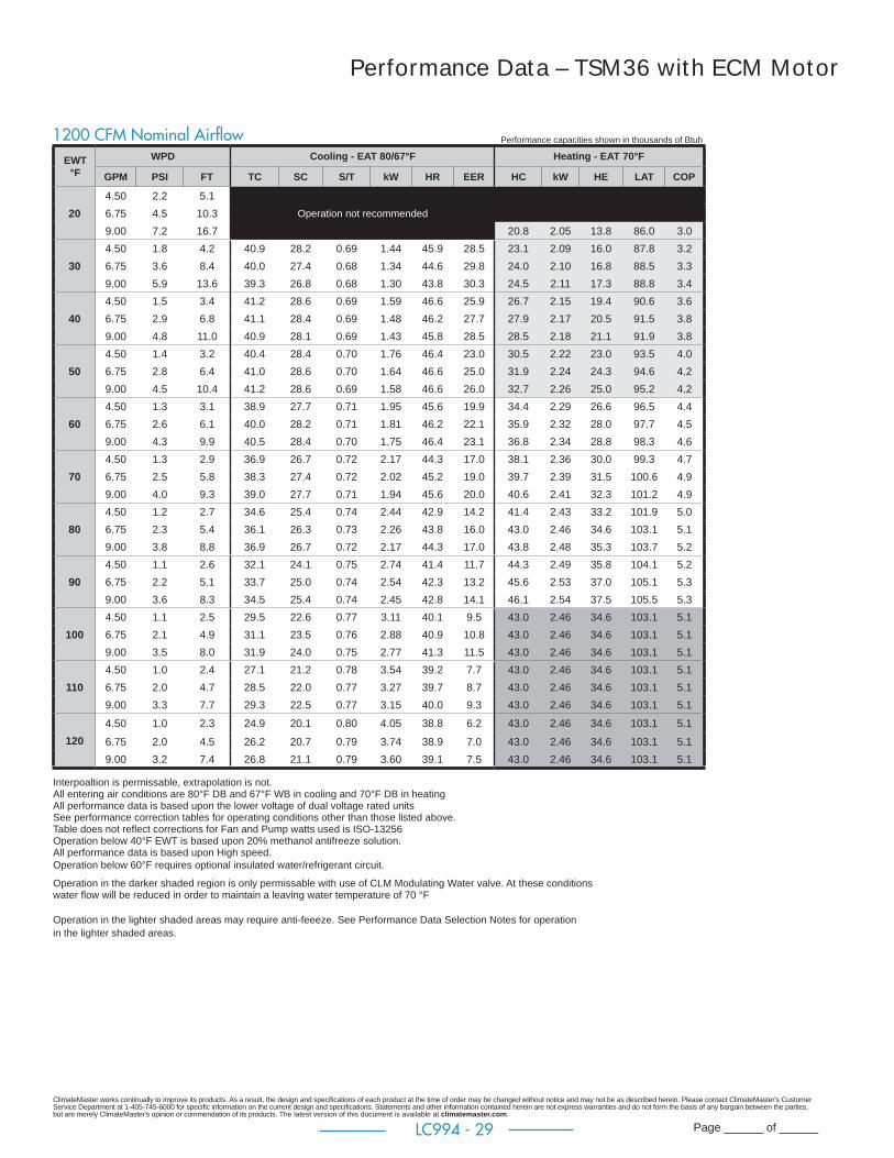
ClimateMaster works continually to improve its products. As a result, the design and specifi cations of each product at the time of order may be changed without notice and may not be as described herein. Please contact ClimateMaster's Customer Service Department at 1-405-745-6000 for specifi c information on the current design and specifi cations. Statements and other information contained herein are not express warranties and do not form the basis of any bargain between the parties, but are merely ClimateMaster's opinion or commendation of its products. The latest version of this document is available at climatemaster.com.
Page ______ of ______LC994 - 29
Performance Data – TSM36 with ECM Motor
EWT °F
WPD Cooling - EAT 80/67°F Heating - EAT 70°F
GPM PSI FT TC SC S/T kW HR EER HC kW HE LAT COP
204.50 2.2 5.16.75 4.5 10.3 Operation not recommended
9.00 7.2 16.7 20.8 2.05 13.8 86.0 3.0
304.50 1.8 4.2 40.9 28.2 0.69 1.44 45.9 28.5 23.1 2.09 16.0 87.8 3.26.75 3.6 8.4 40.0 27.4 0.68 1.34 44.6 29.8 24.0 2.10 16.8 88.5 3.39.00 5.9 13.6 39.3 26.8 0.68 1.30 43.8 30.3 24.5 2.11 17.3 88.8 3.4
404.50 1.5 3.4 41.2 28.6 0.69 1.59 46.6 25.9 26.7 2.15 19.4 90.6 3.66.75 2.9 6.8 41.1 28.4 0.69 1.48 46.2 27.7 27.9 2.17 20.5 91.5 3.89.00 4.8 11.0 40.9 28.1 0.69 1.43 45.8 28.5 28.5 2.18 21.1 91.9 3.8
504.50 1.4 3.2 40.4 28.4 0.70 1.76 46.4 23.0 30.5 2.22 23.0 93.5 4.06.75 2.8 6.4 41.0 28.6 0.70 1.64 46.6 25.0 31.9 2.24 24.3 94.6 4.29.00 4.5 10.4 41.2 28.6 0.69 1.58 46.6 26.0 32.7 2.26 25.0 95.2 4.2
604.50 1.3 3.1 38.9 27.7 0.71 1.95 45.6 19.9 34.4 2.29 26.6 96.5 4.46.75 2.6 6.1 40.0 28.2 0.71 1.81 46.2 22.1 35.9 2.32 28.0 97.7 4.59.00 4.3 9.9 40.5 28.4 0.70 1.75 46.4 23.1 36.8 2.34 28.8 98.3 4.6
704.50 1.3 2.9 36.9 26.7 0.72 2.17 44.3 17.0 38.1 2.36 30.0 99.3 4.76.75 2.5 5.8 38.3 27.4 0.72 2.02 45.2 19.0 39.7 2.39 31.5 100.6 4.99.00 4.0 9.3 39.0 27.7 0.71 1.94 45.6 20.0 40.6 2.41 32.3 101.2 4.9
804.50 1.2 2.7 34.6 25.4 0.74 2.44 42.9 14.2 41.4 2.43 33.2 101.9 5.06.75 2.3 5.4 36.1 26.3 0.73 2.26 43.8 16.0 43.0 2.46 34.6 103.1 5.19.00 3.8 8.8 36.9 26.7 0.72 2.17 44.3 17.0 43.8 2.48 35.3 103.7 5.2
904.50 1.1 2.6 32.1 24.1 0.75 2.74 41.4 11.7 44.3 2.49 35.8 104.1 5.26.75 2.2 5.1 33.7 25.0 0.74 2.54 42.3 13.2 45.6 2.53 37.0 105.1 5.39.00 3.6 8.3 34.5 25.4 0.74 2.45 42.8 14.1 46.1 2.54 37.5 105.5 5.3
1004.50 1.1 2.5 29.5 22.6 0.77 3.11 40.1 9.5 43.0 2.46 34.6 103.1 5.16.75 2.1 4.9 31.1 23.5 0.76 2.88 40.9 10.8 43.0 2.46 34.6 103.1 5.19.00 3.5 8.0 31.9 24.0 0.75 2.77 41.3 11.5 43.0 2.46 34.6 103.1 5.1
1104.50 1.0 2.4 27.1 21.2 0.78 3.54 39.2 7.7 43.0 2.46 34.6 103.1 5.16.75 2.0 4.7 28.5 22.0 0.77 3.27 39.7 8.7 43.0 2.46 34.6 103.1 5.19.00 3.3 7.7 29.3 22.5 0.77 3.15 40.0 9.3 43.0 2.46 34.6 103.1 5.1
1204.50 1.0 2.3 24.9 20.1 0.80 4.05 38.8 6.2 43.0 2.46 34.6 103.1 5.1
6.75 2.0 4.5 26.2 20.7 0.79 3.74 38.9 7.0 43.0 2.46 34.6 103.1 5.19.00 3.2 7.4 26.8 21.1 0.79 3.60 39.1 7.5 43.0 2.46 34.6 103.1 5.1
Performance capacities shown in thousands of Btuh1200 CFM Nominal Airfl ow
Interpoaltion is permissable, extrapolation is not. All entering air conditions are 80°F DB and 67°F WB in cooling and 70°F DB in heating All performance data is based upon the lower voltage of dual voltage rated units See performance correction tables for operating conditions other than those listed above. Table does not refl ect corrections for Fan and Pump watts used is ISO-13256 Operation below 40°F EWT is based upon 20% methanol antifreeze solution. All performance data is based upon High speed.Operation below 60°F requires optional insulated water/refrigerant circuit. Operation in the darker shaded region is only permissable with use of CLM Modulating Water valve. At these conditions water fl ow will be reduced in order to maintain a leaving water temperature of 70 °F
Operation in the lighter shaded areas may require anti-feeeze. See Performance Data Selection Notes for operation in the lighter shaded areas.
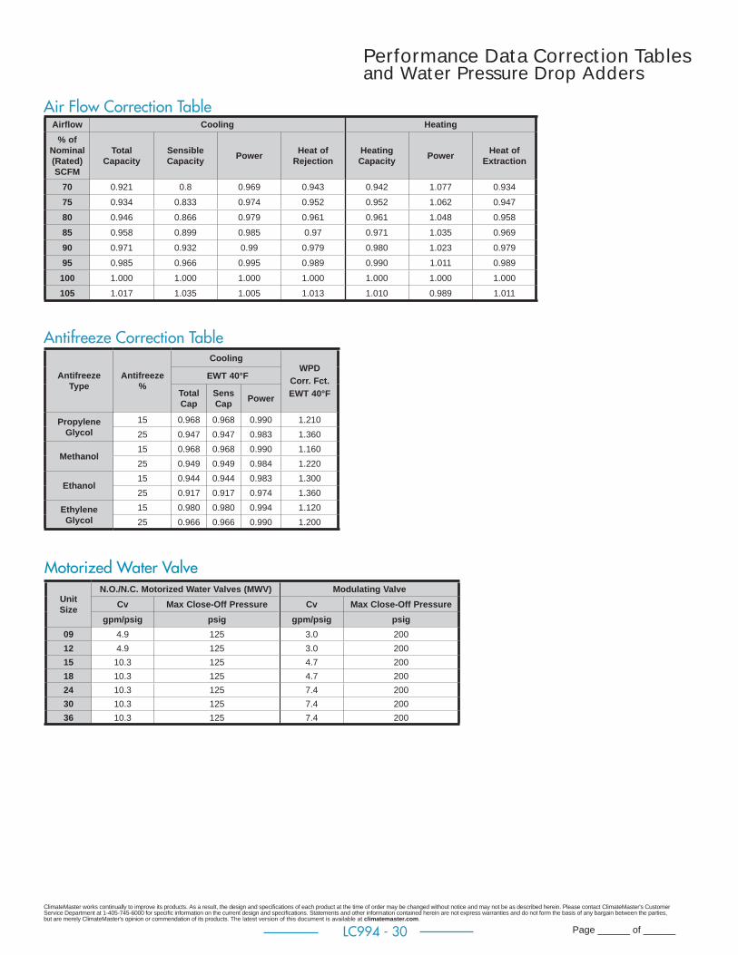
ClimateMaster works continually to improve its products. As a result, the design and specifi cations of each product at the time of order may be changed without notice and may not be as described herein. Please contact ClimateMaster's Customer Service Department at 1-405-745-6000 for specifi c information on the current design and specifi cations. Statements and other information contained herein are not express warranties and do not form the basis of any bargain between the parties, but are merely ClimateMaster's opinion or commendation of its products. The latest version of this document is available at climatemaster.com.
Page ______ of ______LC994 - 30
Performance Data Correction Tablesand Water Pressure Drop Adders
Air Flow Correction Table
Antifreeze Correction Table
Antifreeze Type
Antifreeze %
CoolingWPD
Corr. Fct.EWT 40°F
EWT 40°F
Total Cap
Sens Cap Power
Propylene Glycol
15 0.968 0.968 0.990 1.21025 0.947 0.947 0.983 1.360
Methanol15 0.968 0.968 0.990 1.16025 0.949 0.949 0.984 1.220
Ethanol15 0.944 0.944 0.983 1.30025 0.917 0.917 0.974 1.360
Ethylene Glycol
15 0.980 0.980 0.994 1.12025 0.966 0.966 0.990 1.200
Airfl ow Cooling Heating% of
Nominal (Rated) SCFM
Total Capacity
Sensible Capacity Power Heat of
RejectionHeating Capacity Power Heat of
Extraction
70 0.921 0.8 0.969 0.943 0.942 1.077 0.934
75 0.934 0.833 0.974 0.952 0.952 1.062 0.947
80 0.946 0.866 0.979 0.961 0.961 1.048 0.958
85 0.958 0.899 0.985 0.97 0.971 1.035 0.969
90 0.971 0.932 0.99 0.979 0.980 1.023 0.979
95 0.985 0.966 0.995 0.989 0.990 1.011 0.989
100 1.000 1.000 1.000 1.000 1.000 1.000 1.000
105 1.017 1.035 1.005 1.013 1.010 0.989 1.011
Motorized Water Valve
Unit Size
N.O./N.C. Motorized Water Valves (MWV) Modulating ValveCv Max Close-Off Pressure Cv Max Close-Off Pressure
gpm/psig psig gpm/psig psig09 4.9 125 3.0 20012 4.9 125 3.0 20015 10.3 125 4.7 20018 10.3 125 4.7 20024 10.3 125 7.4 20030 10.3 125 7.4 20036 10.3 125 7.4 200
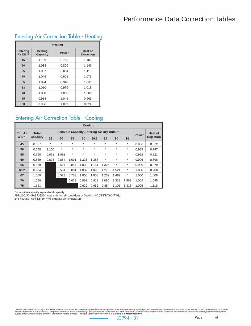
ClimateMaster works continually to improve its products. As a result, the design and specifi cations of each product at the time of order may be changed without notice and may not be as described herein. Please contact ClimateMaster's Customer Service Department at 1-405-745-6000 for specifi c information on the current design and specifi cations. Statements and other information contained herein are not express warranties and do not form the basis of any bargain between the parties, but are merely ClimateMaster's opinion or commendation of its products. The latest version of this document is available at climatemaster.com.
Page ______ of ______LC994 - 31
Performance Data Correction Tables
Entering Air Correction Table - CoolingCooling
Ent. Air WB ºF
Total Capacity
Sensible Capacity-Entering Air Dry Bulb, °FPower Heat of
Rejection65 70 75 80 80.6 85 90 95
45 0.557 * * * * * * * * 0.986 0.672
50 0.658 1.100 * * * * * * * 0.989 0.747
55 0.758 0.861 1.091 * * * * * * 0.992 0.821
60 0.859 0.623 0.854 1.091 1.325 1.383 * * * 0.996 0.896
65 0.960 * 0.617 0.857 1.093 1.151 1.326 * * 0.999 0.970
66.2 0.984 * 0.561 0.801 1.037 1.095 1.270 1.521 * 1.000 0.988
67 1.000 * 0.523 0.763 1.000 1.058 1.232 1.482 * 1.000 1.000
70 1.060 * * 0.623 0.861 0.919 1.090 1.339 1.563 1.002 1.045
75 1.161 * * * 0.629 0.686 0.854 1.101 1.318 1.005 1.119
* = Sensible capacity equals total capacityAHRI/ISO/ASHRAE 13256-1 uses entering air conditions of Cooling - 80.6°F DB/66.2°F WB, and Heating - 68°F DB/59°F WB entering air temperature
Entering Air Correction Table - HeatingHeating
EnteringAir DB°F
HeatingCapacity Power Heat of
Extraction
45 1.109 0.763 1.183
50 1.088 0.809 1.146
55 1.067 0.854 1.110
60 1.045 0.901 1.075
65 1.024 0.948 1.039
68 1.010 0.979 1.015
70 1.000 1.000 1.000
75 0.984 1.046 0.965
80 0.956 1.099 0.924

ClimateMaster works continually to improve its products. As a result, the design and specifi cations of each product at the time of order may be changed without notice and may not be as described herein. Please contact ClimateMaster's Customer Service Department at 1-405-745-6000 for specifi c information on the current design and specifi cations. Statements and other information contained herein are not express warranties and do not form the basis of any bargain between the parties, but are merely ClimateMaster's opinion or commendation of its products. The latest version of this document is available at climatemaster.com.
Page ______ of ______LC994 - 32
Blower Performance Data TSM09
External Static Pressure (in. wg)
PSC
- Lo
w S
tatic
Speed Tap 0.0 0.1 0.2 0.3
LowRPM 760 870
Power (W) 59 54CFM 290 270
MediumRPM 890 940 1000
Power (W) 71 66 61CFM 350 310 270
HighRPM 990 1060 1080 1100
Power (W) 85 80 75 69CFM 400 370 310 240
ECM
- C
onst
ant T
orqu
e
Speed Tap 0.0 0.1 0.2 0.3
1RPM 680
Power (W) 20CFM 250
2RPM 760 870
Power (W) 27 30CFM 290 270
3RPM 930 1000 1100 1180
Power (W) 43 47 51 54CFM 370 340 320 290
4RPM 1010 1070 1160 1240
Power (W) 54 58 62 66CFM 410 380 360 330
ECM
- C
onst
ant
Volu
me
CFM 0.0 0.1 0.2 0.3
250RPM 680 830 960 1120
Power (W) 22 30 38 47
300RPM 780 920 1060 1200
Power (W) 29 38 48 58
350RPM 890 1020 1160 1280
Power (W) 40 50 62 73
400RPM 990 1110 1240 1340
Power (W) 52 65 79 92
TSM09
All data is presented as lowest of nameplate voltage. All data is shown wet coil with clean 1" fi lter. All data is ran at 80°F DB and 67°F WB. CFM Tolerance is 7% RPM/Watt Tolerance 10%
Denotes operation not recommended
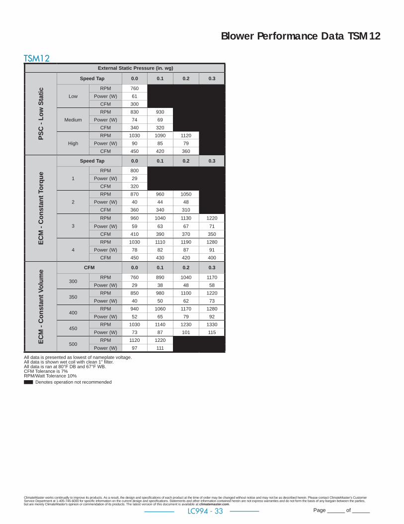
ClimateMaster works continually to improve its products. As a result, the design and specifi cations of each product at the time of order may be changed without notice and may not be as described herein. Please contact ClimateMaster's Customer Service Department at 1-405-745-6000 for specifi c information on the current design and specifi cations. Statements and other information contained herein are not express warranties and do not form the basis of any bargain between the parties, but are merely ClimateMaster's opinion or commendation of its products. The latest version of this document is available at climatemaster.com.
Page ______ of ______LC994 - 33
Blower Performance Data TSM12
External Static Pressure (in. wg)
PSC
- Lo
w S
tatic
Speed Tap 0.0 0.1 0.2 0.3
LowRPM 760
Power (W) 61CFM 300
MediumRPM 830 930
Power (W) 74 69CFM 340 320
HighRPM 1030 1090 1120
Power (W) 90 85 79CFM 450 420 360
ECM
- C
onst
ant T
orqu
e
Speed Tap 0.0 0.1 0.2 0.3
1RPM 800
Power (W) 29CFM 320
2RPM 870 960 1050
Power (W) 40 44 48CFM 360 340 310
3RPM 960 1040 1130 1220
Power (W) 59 63 67 71CFM 410 390 370 350
4RPM 1030 1110 1190 1280
Power (W) 78 82 87 91CFM 450 430 420 400
ECM
- C
onst
ant V
olum
e CFM 0.0 0.1 0.2 0.3
300RPM 760 890 1040 1170
Power (W) 29 38 48 58
350RPM 850 980 1100 1220
Power (W) 40 50 62 73
400RPM 940 1060 1170 1280
Power (W) 52 65 79 92
450RPM 1030 1140 1230 1330
Power (W) 73 87 101 115
500RPM 1120 1220
Power (W) 97 111
TSM12
All data is presented as lowest of nameplate voltage. All data is shown wet coil with clean 1" fi lter. All data is ran at 80°F DB and 67°F WB. CFM Tolerance is 7% RPM/Watt Tolerance 10%
Denotes operation not recommended

ClimateMaster works continually to improve its products. As a result, the design and specifi cations of each product at the time of order may be changed without notice and may not be as described herein. Please contact ClimateMaster's Customer Service Department at 1-405-745-6000 for specifi c information on the current design and specifi cations. Statements and other information contained herein are not express warranties and do not form the basis of any bargain between the parties, but are merely ClimateMaster's opinion or commendation of its products. The latest version of this document is available at climatemaster.com.
Page ______ of ______LC994 - 34
Blower Performance Data TSM15
External Static Pressure (in. wg)
PSC
- Lo
w S
tatic
Speed Tap 0.0 0.1 0.2 0.3
LowRPM 600
Power (W) 153CFM 440
MediumRPM 680 740 810 870
Power (W) 183 177 172 166CFM 520 500 480 450
HighRPM 810 860 900 950
Power (W) 224 215 205 196CFM 650 640 610 570
ECM
- C
onst
ant T
orqu
e
Speed Tap 0.0 0.1 0.2 0.3
1RPM 590
Power (W) 41CFM 430
2RPM 660 710 760 810
Power (W) 49 59 59 59CFM 500 460 410 370
3RPM 760 800 840 890
Power (W) 77 77 77 86CFM 600 570 520 480
4RPM 780 830 870 910
Power (W) 92 92 103 103CFM 620 600 560 520
5RPM 870 900 940 990
Power (W) 120 120 130 130CFM 710 690 660 630
ECM
- C
onst
ant V
olum
e CFM 0.0 0.1 0.2 0.3
450RPM 610 700 790 870
Power (W) 39 53 67 82
500RPM 660 740 820 900
Power (W) 50 64 78 93
600RPM 760 830 890 970
Power (W) 83 97 111 125
650RPM 810 870 930 1000
Power (W) 104 118 133 147
700RPM 860 910 960 1030
Power (W) 125 140 155 170
TSM15
All data is presented as lowest of nameplate voltage. All data is shown wet coil with clean 1" fi lter. All data is ran at 80°F DB and 67°F WB. CFM Tolerance is 7% RPM/Watt Tolerance 10%
Denotes operation not recommended
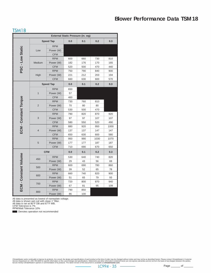
ClimateMaster works continually to improve its products. As a result, the design and specifi cations of each product at the time of order may be changed without notice and may not be as described herein. Please contact ClimateMaster's Customer Service Department at 1-405-745-6000 for specifi c information on the current design and specifi cations. Statements and other information contained herein are not express warranties and do not form the basis of any bargain between the parties, but are merely ClimateMaster's opinion or commendation of its products. The latest version of this document is available at climatemaster.com.
Page ______ of ______LC994 - 35
Blower Performance Data TSM18
External Static Pressure (in. wg)
PSC
- Lo
w S
tatic
Speed Tap 0.0 0.1 0.2 0.3
LowRPM
Power (W)CFM
MediumRPM 600 660 730 810
Power (W) 182 176 170 165CFM 520 500 470 440
HighRPM 750 790 840 900
Power (W) 221 212 203 194CFM 660 630 600 570
ECM
- C
onst
ant T
orqu
e
Speed Tap 0.0 0.1 0.2 0.3
1RPM 650
Power (W) 57CFM 460
2RPM 730 760 810
Power (W) 70 80 80CFM 530 500 470
3RPM 790 820 870 920
Power (W) 97 97 107 107CFM 580 550 520 490
4RPM 880 920 950 1000
Power (W) 137 137 147 147CFM 650 630 600 580
5RPM 950 990 1030 1070
Power (W) 177 177 187 187CFM 710 690 670 650
ECM
- C
onst
ant V
olum
e CFM 0.0 0.1 0.2 0.3
450RPM 530 640 740 820
Power (W) 29 43 56 69
500RPM 600 690 780 860
Power (W) 39 52 65 78
600RPM 660 740 820 900
Power (W) 51 65 79 93
700RPM 720 800 870 940
Power (W) 67 81 95 109
800RPM 790 850 910 980
Power (W) 86 100 115 130
TSM18
All data is presented as lowest of nameplate voltage. All data is shown wet coil with clean 1" fi lter. All data is ran at 80°F DB and 67°F WB. CFM Tolerance is 7% RPM/Watt Tolerance 10%
Denotes operation not recommended
ClimateMaster works continually to improve its products. As a result, the design and specifi cations of each product at the time of order may be changed without notice and may not be as described herein. Please contact ClimateMaster's Customer Service Department at 1-405-745-6000 for specifi c information on the current design and specifi cations. Statements and other information contained herein are not express warranties and do not form the basis of any bargain between the parties, but are merely ClimateMaster's opinion or commendation of its products. The latest version of this document is available at climatemaster.com.
Page ______ of ______LC994 - 36
Blower Performance Data TSM24
External Static Pressure (in. wg)
PSC
- Lo
w S
tatic
Speed Tap 0.0 0.1 0.2 0.3
LowRPM
Power (W)CFM
MediumRPM 640 690 750 820
Power (W) 236 227 217 208CFM 690 670 640 590
HighRPM 710 760 820 880
Power (W) 297 285 272 260CFM 860 840 810 770
ECM
- C
onst
ant T
orqu
e
Speed Tap 0.0 0.1 0.2 0.3
1RPM 640 690 730
Power (W) 62 68 76CFM 710 660 600
2RPM 690 730 780 850
Power (W) 89 97 102 109CFM 820 770 720 670
3RPM 740 780 830 890
Power (W) 120 129 134 143CFM 930 880 830 790
4RPM 830 880 920
Power (W) 169 173 185CFM 990 950 910
5RPM
Power (W)CFM
ECM
- C
onst
ant V
olum
e CFM 0.0 0.1 0.2 0.3
600RPM 600 660 730 830
Power (W) 70 87 104 122
700RPM 640 700 770 860
Power (W) 96 115 134 153
800RPM 680 750 820 890
Power (W) 122 143 164 184
900RPM 720 790 860 920
Power (W) 155 176 197 218
950RPM 740 810 880 930
Power (W) 193 214 234 255
TSM24
All data is presented as lowest of nameplate voltage. All data is shown wet coil with clean 1" fi lter. All data is ran at 80°F DB and 67°F WB. CFM Tolerance is 7% RPM/Watt Tolerance 10%
Denotes operation not recommended

ClimateMaster works continually to improve its products. As a result, the design and specifi cations of each product at the time of order may be changed without notice and may not be as described herein. Please contact ClimateMaster's Customer Service Department at 1-405-745-6000 for specifi c information on the current design and specifi cations. Statements and other information contained herein are not express warranties and do not form the basis of any bargain between the parties, but are merely ClimateMaster's opinion or commendation of its products. The latest version of this document is available at climatemaster.com.
Page ______ of ______LC994 - 37
Blower Performance Data TSM30
External Static Pressure (in. wg)
PSC
- Lo
w S
tatic
Speed Tap 0.0 0.1 0.2 0.3
LowRPM 860 850 890 930
Power (W) 344 328 311 295CFM 1010 980 940 880
MediumRPM 920 910 940 970
Power (W) 385 365 345 325CFM 1100 1070 1020 960
HighRPM 1090
Power (W) 422CFM 1240
ECM
- C
onst
ant T
orqu
e
Speed Tap 0.0 0.1 0.2 0.3
1RPM 770 770 800
Power (W) 105 113 118CFM 880 830 780
2RPM 860 840 880 940
Power (W) 151 158 165 170CFM 1000 960 920 900
3RPM 950 920 960 1000
Power (W) 210 217 225 229CFM 1140 1100 1070 1030
4RPM 1000 1040 1060
Power (W) 285 295 299CFM 1230 1200 1160
5RPM
Power (W)CFM
ECM
- C
onst
ant
Volu
me
CFM 0.0 0.1 0.2 0.3
750RPM 690 720 790 880
Power (W) 109 133 157 182
875RPM 770 790 860 930
Power (W) 157 183 209 235
1000RPM 860 870 930 990
Power (W) 219 247 275 303
1100RPM 920 920 980 1030
Power (W) 310 336 361 387
TSM30
All data is presented as lowest of nameplate voltage. All data is shown wet coil with clean 1" fi lter. All data is ran at 80°F DB and 67°F WB. CFM Tolerance is 7% RPM/Watt Tolerance 10%
Denotes operation not recommended
ClimateMaster works continually to improve its products. As a result, the design and specifi cations of each product at the time of order may be changed without notice and may not be as described herein. Please contact ClimateMaster's Customer Service Department at 1-405-745-6000 for specifi c information on the current design and specifi cations. Statements and other information contained herein are not express warranties and do not form the basis of any bargain between the parties, but are merely ClimateMaster's opinion or commendation of its products. The latest version of this document is available at climatemaster.com.
Page ______ of ______LC994 - 38
Blower Performance Data TSM36
External Static Pressure (in. wg)
PSC
- Lo
w S
tatic
Speed Tap 0.0 0.1 0.2 0.3
LowRPM 870 900
Power (W) 328 311CFM 970 930
MediumRPM 940 970 990 1020
Power (W) 363 344 324 305CFM 1080 1040 980 910
HighRPM 1050 1090 1120 1150
Power (W) 468 441 415 389CFM 1340 1280 1190 1090
ECM
- C
onst
ant T
orqu
e
Speed Tap 0.0 0.1 0.2 0.3
1RPM 880 910 950
Power (W) 131 132 141CFM 990 950 910
2RPM 970 1010 1050 1090
Power (W) 191 193 199 209CFM 1130 1100 1080 1040
3RPM 1070 1110 1150 1170
Power (W) 267 269 276 288CFM 1280 1260 1240 1190
4RPM 1190 1210 1250 1270
Power (W) 373 376 387 398CFM 1450 1420 1410 1370
5RPM
Power (W)CFM
ECM
- C
onst
ant
Volu
me
CFM 0.0 0.1 0.2 0.3
900RPM 820 880 940 1010
Power (W) 183 208 234 260
1050RPM 920 980 1030 1100
Power (W) 272 301 329 358
1200RPM 1020 1070 1120 1180
Power (W) 362 393 425 456
1350RPM 1120 1170 1220 1260
Power (W) 509 534 560 585
TSM36
All data is presented as lowest of nameplate voltage. All data is shown wet coil with clean 1" fi lter. All data is ran at 80°F DB and 67°F WB. CFM Tolerance is 7% RPM/Watt Tolerance 10%
Denotes operation not recommended
ClimateMaster works continually to improve its products. As a result, the design and specifi cations of each product at the time of order may be changed without notice and may not be as described herein. Please contact ClimateMaster's Customer Service Department at 1-405-745-6000 for specifi c information on the current design and specifi cations. Statements and other information contained herein are not express warranties and do not form the basis of any bargain between the parties, but are merely ClimateMaster's opinion or commendation of its products. The latest version of this document is available at climatemaster.com.
Page ______ of ______LC994 - 39
TSM Non Ducted ECM-CV 88 and 80" Cabinets
ECM-CV Blower Performance Data
All data wet coil clean fi lter.
All units AHRI/ISO/ASHRAE 13256-1 rated on CFM shown on performance data page.Airfl ow is rated at lowest Voltage if unit is dual Voltage rated, i.e. 208V for 208-230V units.Shipped on default settings. C = Cooling; H = Heating; D = Dehumidifi cation.Change from default setting with service tool (ACDU03C) or Communicating thermostat (ATC32U03C).Airfl ow is controlled within 7% up to the max ESP with recommended supply air openings and sizes (See SA Grille Table).TSM15-36 ramp default is 30.
TranquilityModel Range
Cooling Mode Dehumid Mode Heating modeConstantFan Only
Mode
Hi FanMode
AuxEmergModeStg 1 Stg 2 Stg 1 Stg 2 Stg 1 Stg 2
TSM09
Default 250 350 250 300 250 350 250 250 400
Maximum 400 400 400 400 400 400 400 400 400
Minimum 250 250 250 250 250 250 250 250 250
TSM12
Default 300 400 300 350 300 400 300 300 500
Maximum 500 500 500 500 500 500 500 500 500
Minimum 300 300 300 300 300 300 300 300 300
TSM15
Default 500 600 500 500 500 600 500 500 600
Maximum 700 700 700 700 700 700 700 700 700
Minimum 500 500 500 500 500 500 500 500 500
TSM18
Default 600 700 600 600 600 700 500 500 700
Maximum 800 800 800 800 800 800 800 800 800
Minimum 600 600 500 500 600 600 500 500 600
TSM24
Default 650 850 650 650 650 850 600 600 850
Maximum 950 950 950 950 950 950 950 950 950
Minimum 650 650 600 600 650 650 600 600 650
TSM30
Default 850 1000 850 850 900 1000 700 700 1000
Maximum 1100 1100 900 1100 1100 1100 1100 1100 1100
Minimum 850 850 800 900 900 900 700 700 900
TSM36
Default 900 1200 900 900 1000 1350 900 900 1200
Maximum 1250 1250 1250 1250 1350 1350 1250 1250 1350
Minimum 900 900 900 900 900 900 900 900 1000
ClimateMaster works continually to improve its products. As a result, the design and specifi cations of each product at the time of order may be changed without notice and may not be as described herein. Please contact ClimateMaster's Customer Service Department at 1-405-745-6000 for specifi c information on the current design and specifi cations. Statements and other information contained herein are not express warranties and do not form the basis of any bargain between the parties, but are merely ClimateMaster's opinion or commendation of its products. The latest version of this document is available at climatemaster.com.
Page ______ of ______LC994 - 40
Physical Data
Model 09 12 15 18 24 30 36
Compressor (1 Each) Rotary Scroll
Factory Charge HFC-410A (oz) [kg] 35 [.99] 43 [2.69] 53 [3.31] 71 [4.44] 66 [4.13] 75 [2.13]
Motor & BlowerPSC (HP) [W] 1/30 [25] 1/15 [50] 1/8 [93] 1/6 [124] 1/3 [249]
ECM Constant Volume (HP) [W] 1/8 [93] 1/3 [249] 1/3 [249] 1/2 [373]
ECM Constant Torque (HP) [W] 1/4 [186] 1/3 [249] 1/2 [373] 3/4 [560]
Blower Wheel Size (diam x w) - (in) [mm] 6.75 x 7.25 [165 x 184]
9.5 x 7.12 [241 x 180]
10.63 x 8.0 [270 x 203]
Chassis Air Coil
Air Coil Dimensions (h x w) - (in) [mm] 28 x 12.625 [711 x 321 ]
28 x 14 [711 x 356]
30 x 18 [762 x 457]
Standard Filter - 1" [25.4 mm], (w x h) - (in) [mm]
14 x 30 [356 x 762]
16 x 30 [406 x 762]
20 x 32 [508 x 813]
Coax Volume (Gallons) [ l ] 0.26 [.98] 0.36 [1.4] 0.60 [2.3]
Hose Size (in) 1/2 3/4 1
WeightChassis - (lbs) [kg] 110 [50] 117 [53] 123 [56] 125 [57] 186 [84] 190 [86] 192 [87]
Cabinet - (lbs) [kg] 125 [57] 189 [86] 243 [110]
Unit wiring diagrams available at www.climatemaster.com. Select 'Commercial Professional ', ' Literature ', ' Wiring Diagrams'.
Unit Maximum Water Working PressureOptions Max Pressure PSIG [kPa]
Base Unit (Hoses) 400 [2757]
Internal Secondary Pump (ISP) 200 [1.378]
Internal Motorized Water Valve (MWV) 300 [2,068]
Internal Modulating Valve 300 [2,068] Internal Auto Flow Valve 400 [2,757]
Use the lowest maximum pressure rating when multiple options are combined.* Units with water valve have 300 [2068] High Pressure Water Switch – 250 [1723] Auto Reset

ClimateMaster works continually to improve its products. As a result, the design and specifi cations of each product at the time of order may be changed without notice and may not be as described herein. Please contact ClimateMaster's Customer Service Department at 1-405-745-6000 for specifi c information on the current design and specifi cations. Statements and other information contained herein are not express warranties and do not form the basis of any bargain between the parties, but are merely ClimateMaster's opinion or commendation of its products. The latest version of this document is available at climatemaster.com.
Page ______ of ______LC994 - 41
Electrical Data - PSC Low Static Motor (208/230V) and (265V)
Model # Voltage Code "G"
Compressor Blower Motor
Pump Option Total Unit
FLA
Min Circuit Amps
Max Fuse Amps
RLA LRA FLA FLA
TSM09
208/230-60-1
3.7 22 0.30.0 4.0 4.9 150.6 4.7 5.6 15
TSM12 4.6 30 0.70.0 5.3 6.5 150.6 6.0 7.1 15
TSM15 5.6 29 1.00.0 6.6 8.0 150.6 7.2 8.6 15
TSM18 6.6 33 1.00.0 7.6 9.3 150.6 8.2 9.9 15
TSM24 12.8 58.3 1.10.0 13.9 17.1 250.6 14.5 17.7 30
TSM30 12.8 64 2.70.0 15.5 18.7 300.6 16.1 19.3 30
TSM36 14.1 77 2.70.0 16.8 20.3 30
0.6 17.4 21.0 35
PSC Low Static Motor (208/230V)
PSC Low Static Motor (265V)
Model # Voltage Code "E"
Compressor Blower Motor
Pump Option Total Unit
FLA
Min Circuit Amps
Max Fuse Amps
RLA LRA FLA FLA
TSM09
265-60-1
3.5 22 0.30.0 3.8 4.7 15
0.6 4.4 5.3 15
TSM12 3.9 23 0.60.0 4.5 5.4 15
0.6 5.1 6.1 15
TSM15 5.0 28 0.90.0 5.9 7.1 15
0.6 6.5 7.8 15
TSM18 5.6 28 0.90.0 6.5 7.9 15
0.6 7.1 8.5 15
TSM24 9.6 54 0.90.0 10.5 12.9 20
0.6 11.1 13.5 20
TSM30 10.9 60 2.00.0 12.9 15.6 25
0.6 13.5 16.3 25
TSM36 12.2 72 2.00.0 14.2 17.3 25
0.6 14.8 17.9 30
Unit wiring diagrams available at www.climatemaster.com. Select 'Commercial Professional ', ' Literature ', ' Wiring Diagrams'.
ClimateMaster works continually to improve its products. As a result, the design and specifi cations of each product at the time of order may be changed without notice and may not be as described herein. Please contact ClimateMaster's Customer Service Department at 1-405-745-6000 for specifi c information on the current design and specifi cations. Statements and other information contained herein are not express warranties and do not form the basis of any bargain between the parties, but are merely ClimateMaster's opinion or commendation of its products. The latest version of this document is available at climatemaster.com.
Page ______ of ______LC994 - 42
Electrical Data - ECM-CV Motor (208/230V) and (265V)
Model # Voltage Code "G"
Compressor Blower Motor
Pump Option Total Unit
FLA
Min Circuit Amps
Max Fuse Amps
RLA LRA FLA FLA
TSM09
208/230-60-1
3.7 22 1.50.0 5.2 6.1 150.6 5.8 6.8 15
TSM12 4.6 30 1.50.0 6.1 7.3 150.6 6.8 7.9 15
TSM15 5.6 29 2.60.0 8.2 9.6 150.6 8.8 10.2 15
TSM18 6.6 33 2.60.0 9.2 10.9 150.6 9.8 11.5 15
TSM24 12.8 58.3 2.60.0 15.4 18.6 300.6 16.0 19.2 30
TSM30 12.8 64 3.90.0 16.7 19.9 300.6 17.3 20.5 30
TSM36 14.1 77 3.90.0 18.0 21.5 35
0.6 18.6 22.2 35
ECM-CV Motor (208/230V)
ECM-CV Motor (265V)
Model # Voltage Code "E"
Compressor Blower Motor
Pump Option Total Unit
FLA
Min Circuit Amps
Max Fuse Amps
RLA LRA FLA FLA
TSM09
265-60-1
3.5 22 1.40.0 4.9 5.8 150.6 5.5 6.4 15
TSM12 3.9 23 1.40.0 5.3 6.2 150.6 5.9 6.9 15
TSM15 5.0 28 2.10.0 7.1 8.4 150.6 7.7 9.0 15
TSM18 5.6 28 2.10.0 7.7 9.1 150.6 8.3 9.7 15
TSM24 9.6 54 2.10.0 11.7 14.1 200.6 12.3 14.7 20
TSM30 10.9 60 3.20.0 14.1 16.8 250.6 14.7 17.5 25
TSM36 12.2 72 3.20.0 15.4 18.5 30
0.6 16.0 19.1 30
Unit wiring diagrams available at www.climatemaster.com. Select 'Commercial Professional ', ' Literature ', ' Wiring Diagrams'.

ClimateMaster works continually to improve its products. As a result, the design and specifi cations of each product at the time of order may be changed without notice and may not be as described herein. Please contact ClimateMaster's Customer Service Department at 1-405-745-6000 for specifi c information on the current design and specifi cations. Statements and other information contained herein are not express warranties and do not form the basis of any bargain between the parties, but are merely ClimateMaster's opinion or commendation of its products. The latest version of this document is available at climatemaster.com.
Page ______ of ______LC994 - 43
Electrical Data - ECM-CT Motor (208/230V) and (265V)
Model # Voltage Code "G"
Compressor Blower Motor
Pump Option Total Unit
FLA
Min Circuit Amps
Max Fuse Amps
RLA LRA FLA FLA
TSM09
208/230-60-1
3.7 22 2.30.0 6.0 6.9 150.6 6.6 7.6 15
TSM12 4.6 30 2.30.0 6.9 8.1 150.6 7.6 8.7 15
TSM15 5.6 29 2.50.0 8.1 9.5 150.6 8.7 10.1 15
TSM18 6.6 33 2.50.0 9.1 10.8 150.6 9.7 11.4 15
TSM24 12.8 58.3 4.30.0 17.1 20.3 300.6 17.7 20.9 30
TSM30 12.8 64 4.30.0 17.1 20.3 300.6 17.7 20.9 30
TSM36 14.1 77 6.10.0 20.2 23.7 35
0.6 20.8 24.4 35
ECM-CT Motor (208/230V)
ECM-CT Motor (265V)
Model # Voltage Code "E"
Compressor Blower Motor
Pump Option Total Unit
FLA
Min Circuit Amps
Max Fuse Amps
RLA LRA FLA FLA
TSM09
265-60-1
3.5 22 2.30.0 5.8 6.7 150.6 6.4 7.3 15
TSM12 3.9 23 2.30.0 6.2 7.1 150.6 6.8 7.8 15
TSM15 5.0 28 2.50.0 7.5 8.8 150.6 8.1 9.4 15
TSM18 5.6 28 2.50.0 8.1 9.5 150.6 8.7 10.1 15
TSM24 9.6 54 4.30.0 13.9 16.3 250.6 14.5 16.9 25
TSM30 10.9 60 4.30.0 15.2 17.9 250.6 15.8 18.6 25
TSM36 12.2 72 6.10.0 18.3 21.4 30
0.6 18.9 22.0 30
Unit wiring diagrams available at www.climatemaster.com. Select 'Commercial Professional ', ' Literature ', ' Wiring Diagrams'.
ClimateMaster works continually to improve its products. As a result, the design and specifi cations of each product at the time of order may be changed without notice and may not be as described herein. Please contact ClimateMaster's Customer Service Department at 1-405-745-6000 for specifi c information on the current design and specifi cations. Statements and other information contained herein are not express warranties and do not form the basis of any bargain between the parties, but are merely ClimateMaster's opinion or commendation of its products. The latest version of this document is available at climatemaster.com.
Page ______ of ______LC994 - 44
Typical Unit - Exploded View
works continually to improve its products. As a result, the design and specifi cations of each product at the time of order may be changed without notice and may not be as described herein. Please contact ClimateMaster's Customement at 1-405-745-6000 for specifi c information on the current design and specifi cations. Statements and other information contained herein are not express warranties and do not form the basis of any bargain between the parties, ClimateMaster's opinion or commendation of its products. The latest version of this document is available at climatemaster.com.
Page ______ of _____LC994 - 44
3B
3A
1K
1A
1B2A
2B
2C2D
2G
1G
1E
1J
1D
1C
1F
2F 2E
3
2
1
Major Components1. TSM Cabinet (Furred-in)
A - fl oating condensate drain pan B - drain P trap C - supply air plenum D - optional surface mount thermostat 2 x 4 box horizontal E - optional disconnect / breaker location F - upper control box (high voltage terminal blocks optional MPC, Lon) G - blower assembly/motor H - risers (not shown) I - shutoffs (not shown) J - fi lter panel K - fi lter
2. TSM Chassis A - compressor with acoustic enclosure, water coil, reversing valve B - data plate C - lower control box (transformer, CXM/DXM2, contactor) D - capacitor E - high and low voltage locking quick connectors F - air coil G- Optional Service Connection (DXM2 Controls only)3. Architectural Acoustic Return Air Panel (G) A - frame B - hinged inner panel4. Hoses (Not Shown)5. Supply Air Grille (Not Shown)6. Thermostat (Not Shown)
Note - Matching labels for visual aid, chassis and cabinet same size and voltage
Note

ClimateMaster works continually to improve its products. As a result, the design and specifi cations of each product at the time of order may be changed without notice and may not be as described herein. Please contact ClimateMaster's Customer Service Department at 1-405-745-6000 for specifi c information on the current design and specifi cations. Statements and other information contained herein are not express warranties and do not form the basis of any bargain between the parties, but are merely ClimateMaster's opinion or commendation of its products. The latest version of this document is available at climatemaster.com.
Page ______ of ______LC994 - 45
TSM – Standard Unit, Furred In Cabinet with Risers
Thin Wall Conduit3/4" (19)
Supply Air KO
Optional 24V Surface Mount T/StatHorizontal (Note 3)
Motor-Blower Assembly
Filter, Throwaway
Return Air OpeningHeat Pump Chassis
Factory TrappedCondensate Drain
(Clamped to Riser Stub and Pan)
Lower Drain Pan
Condensate Drain Riser
Supply Riser
Air coil
24(610)
(Note 7)
OptionalRemoteT/Stat
Conduit
PowerConduit
Return Riser
Flex HoseFilter Panel (Not Shown)
ServiceArea
2.00(51)
Upper Control Box & ElectricalPower Connections
Ball Valves (2) Brazed to Riser
Note 5,6
Top Supply Air KO
1.00 x 1.38 (25 x 35)Supply Air Angles
(Note 6)
(Not To Scale)
Optional motorized water valve, pump, or auto flow regulator valve
Notes:1. All dimensions are in inches (mm).2. The return air/control box side is defi ned as front of cabinet. Supply air K.O.'s and
riser K.O.'s are on all panels. Supply air grilles can be on any side except riser side.3. Units with 24v surface mount T/stat option have 2x4 box factory installed in
horizontal position. Contractor must turn box before dry walling if customer is using vertical thermostat type.
4. Cabinet shown is Style 3, risers back right.5. Supply air K.O.'s can be confi gured in fi eld or in factory.6. If supply air is fi eld confi gured the angles are shipped loose. Quality of angles
depends on your selection of cabinet digits 11 and 12. Break off if needed. Position inside and attach with screws.
7. Service area from fi nished wall, and 4"(102) wider than cabinet.
Front (Risers Shown
Style 3)

ClimateMaster works continually to improve its products. As a result, the design and specifi cations of each product at the time of order may be changed without notice and may not be as described herein. Please contact ClimateMaster's Customer Service Department at 1-405-745-6000 for specifi c information on the current design and specifi cations. Statements and other information contained herein are not express warranties and do not form the basis of any bargain between the parties, but are merely ClimateMaster's opinion or commendation of its products. The latest version of this document is available at climatemaster.com.
Page ______ of ______LC994 - 46
3.125” (70)
39.75” (1100)
Thin wall Conduit3/4" (19)
Supply Air KO
Optional 24V Surface Mount T/StatHorizontal Note 3
Motor-Blower Assembly
Filter, Throwaway
Return Air OpeningHeat Pump Chassis
Factory TrappedCondensate Drain
(Clamped to Riser Stub and Pan)
Lower Drain Pan
Condensate Drain Riser
Supply Riser
Air coil
Note 7
OptionalRemoteT/Stat
Conduit
PowerConduit
Return Riser
Flex Hose
ServiceArea
2.00(51)
Upper Control Box & ElectricalPower Connections
Ball Valves (2) Brazed to Riser
Supply and Return Stubouts
CondensateDrain Stubout
3” (76)
(Copper-.875” O.D.)
24(610)
3” (76)
Note 5,6
Filter Panel (Not Shown)
Top Supply Air KO
1.00 x 1.38 (25 x 35)Supply Air Angles
Note 6
(Not To Scale)
Optional motorized water valve, pump, or auto flow regulator valve
TSM – Master Unit, Furred In Cabinet
Notes:1. All dimensions are in inches (mm).2. The return air/control box side is defi ned as front of cabinet. Supply air K.O.'s and
riser K.O.'s are on all panels. Supply air grilles can be on any side except riser side.3. Units with 24v surface mount T/stat option have 2x4 box factory installed in
horizontal position. Contractor must turn box before dry walling if customer is using vertical thermostat type.
4. Cabinet shown is Style 3, risers back right.5. Supply air K.O.'s can be confi gured in fi eld or in factory.6. If supply air is fi eld confi gured the angles are shipped loose. Quality of angles
depends on your selection of cabinet digits 11 and 12. Break off if needed. Position inside and attach with screws.
7. Service area from fi nished wall, and 4"(102) wider than cabinet.8. Istaller must provide crossover water piping from riser to slave unit. Piping must
have same pressure rating or higher as riser.
ClimateMaster works continually to improve its products. As a result, the design and specifi cations of each product at the time of order may be changed without notice and may not be as described herein. Please contact ClimateMaster's Customer Service Department at 1-405-745-6000 for specifi c information on the current design and specifi cations. Statements and other information contained herein are not express warranties and do not form the basis of any bargain between the parties, but are merely ClimateMaster's opinion or commendation of its products. The latest version of this document is available at climatemaster.com.
Page ______ of ______LC994 - 47
TSM – Slave Unit, Furred In Cabinet, No Risers
Thin Wall Conduit3/4" (19)
Supply Air K.O.
Optional 24V Surface Mount T/StatUpper Control Box & Electrical
Power ConnectionsMotor-Blower Assembly
Filter, Throwaway
Return Air Opening
Factory TrappedCondensate DrainLower Drain Pan
Air coil
OptionalRemoteT/Stat
Conduit
PowerConduit
* For optional 80” (2032) tall cabinet deduct 8(203) from dimensions.
Note: May limit front supply opening size.
8” (203) Minimum3.125” (70)
Heat Pump ChassisFlex Hose
24(610)
ServiceArea
2.00(51)
½” (13) Notes 7
1.00 x 1.38 (25 x 35)Supply Air Angles
Note 5
Riser Pads (4)Note 9
Condensate RubberDrain Hose (Note 8).875 I.D. (22.2)
Final Location of shipped loose Ball Valves (2) with Stub (Note 7). Shutoff handleto be inside cabinet.
A
Front
Filter Panel (Not Shown)
Note 4,5
Horizontal Note 3
Note 6
Top Supply Air KO
(Not To Scale)
Optional motorized water valve, pump, or auto flow regulator valve
Notes:1. All dimensions are in inches (mm).2. The return air/control box side is defi ned as front of cabinet. Supply air K.O.'s and riser K.O.'s are
on all panels. Supply air grilles can be on any side except riser side.3. Units with 24v surface mount T/stat option have 2x4 box factory installed in horizontal position.
Contractor must turn box before dry walling if customer is using vertical thermostat type.4. Supply air K.O.'s can be confi gured in fi eld or in factory.5. If supply air is fi eld confi gured the angles are shipped loose. Quality of angles depends on your
selection of cabinet digits 11 and 12. Break off if needed. Position inside and attach with screws.6. Service area from fi nished wall, and 4"(102) wider than cabinet.7. Ball valve package is shipped loose in cabinet or shipped in bulk as special. Field must position
in cabinet copper protruding 1/2"out of cabinet and connect to master riser stubouts, extend copper if needed.
8. Rubber drain hose is shipped loose and must be connected to drain pan and clamped both ends. Recomend running hard tubing inside and clamping inside so there is future access.
9. Installer must apply riser pads to outside of cabinet to seal supply and return slots.
ClimateMaster works continually to improve its products. As a result, the design and specifi cations of each product at the time of order may be changed without notice and may not be as described herein. Please contact ClimateMaster's Customer Service Department at 1-405-745-6000 for specifi c information on the current design and specifi cations. Statements and other information contained herein are not express warranties and do not form the basis of any bargain between the parties, but are merely ClimateMaster's opinion or commendation of its products. The latest version of this document is available at climatemaster.com.
Page ______ of ______LC994 - 48
Master/Slave Cabinet
2” (50) Minimum extend copper stubs for S/R/C if over 3” (75)
Master Slave
Note 4
RA
R R
RS
S S
RA
Field install P-Trap and clamp both ends. Recomend hard drain connection be extended intocabinet so clamp is always accessable
Field connecthoses in both cabinets- supply to supply and return to return.(Cabinet supply is closest to corner, chassis supply is on left facing air coil)
Field braze valve package onslave side (shutoff with tubing) so shutoff is inside the cabinet
Slave CabinetRiser Pads (4)
Note 4
Notes:1. Contractor must meet all building and fi re code requirements.2. Size riser diameter for both units GPM.3. Master/Slave means both units share common riser.4. Install pads on back of slave cabinet to cover slots used for S/R risers.
ShutoffsInside
Step 1Risers Opposite
Return Air Opening
Approx.
1/4” to 1”(6 to 25)
Push Push
Push
When cabinets are pushed up to risers allow suffient clearance.Shutoffs should be inside cabinet.
Step 2Step 1Risers Adjacent to
Return Air Opening
Final Cabinet Postion
6”(152)
ClimateMaster works continually to improve its products. As a result, the design and specifi cations of each product at the time of order may be changed without notice and may not be as described herein. Please contact ClimateMaster's Customer Service Department at 1-405-745-6000 for specifi c information on the current design and specifi cations. Statements and other information contained herein are not express warranties and do not form the basis of any bargain between the parties, but are merely ClimateMaster's opinion or commendation of its products. The latest version of this document is available at climatemaster.com.
Page ______ of ______LC994 - 49
Cabinet Dimensions
Notes:1. All dimensions are in inches (mm).2. Cabinets have supply air and riser K.O.'s, all panels. Remove only K.O.'s
necessary to confi gure cabinet. Seal any K.O.'s removed by mistake.3. Service area to be width of cabinet plus 4" [102] and 24" [610] from fi nished wall.4. For 9-18 cabinet use drain diagonally across from supply and return risers.
Cabinet Unit SizeALL 88" Cabinet 80" Cabinet
A B C D/F E/G D E F GC1 - C2 TSM09 - 12 17.00 [432] 17.00 [432] 12.00 [305] 6.00 [152] 12.00 [305] 6.00 [152] – 6.00 [152] 12.00 [305]
C3 - C4 TSM15 - 18 19.25 [489] 19.00 [483] 14.00 [356] 6.00 [152] 14.00 [356] 6.00 [152] – 6.00 [152] 12.00 [305]
C5 - C7 TSM24 - 36 24.25 [616] 24.00 [610] 16.00 [406] 8.00 [203] 16.00 [406] 6.00 [152] – 6.00 [152] 12.00 [305]
OPENING
FOR
CHASSIS
Front
of Cabinet
L.H. SIDE FRONT R.H. SIDE BACK(24-36)
BACK(09-18)
66.75
[1695]
35.75
[908]
12.00[305]
3.12 [79]
88.00 [2235] or
80.00 [2032]
(Note 4)
57.00[1259]
6.00[152]
1.25 [32]
2.75 [70]
5.00
(127)
2.12 [54]
1.50 [38]1.50 [38]
1.62 [41]
Front
1.125 DIA (2) Holes(28.6)
High VoltageEntrance
A
C
C
E
C
D
B
C C
FG G
12.12[308]
12.12[308]
12.12[308]
2.88[73]
2.88[73]
5.00[127]
5.00[127]
2.50 x 12.00[64 x 305]
2.25 x 3.00[57 x 76]
Note 4
F
ClimateMaster works continually to improve its products. As a result, the design and specifi cations of each product at the time of order may be changed without notice and may not be as described herein. Please contact ClimateMaster's Customer Service Department at 1-405-745-6000 for specifi c information on the current design and specifi cations. Statements and other information contained herein are not express warranties and do not form the basis of any bargain between the parties, but are merely ClimateMaster's opinion or commendation of its products. The latest version of this document is available at climatemaster.com.
Page ______ of ______LC994 - 50
Cabinet Slot Dimensions and Riser Arrangements
NOTICE! NOTICE! Not all styles will stack above or adjacent to each other. (See Note 8).
3.125” (all sizes)(79)
2.75”(70)
[908]
39.75”35.75” [1100]
± .50” (13)
12.00”[305]
2.25”(57)
3.00”(76)
12.12”(308)
12.00”(305)
5.00”(127)
5.00”(127)
2.88”(73)
2.50”(64)
FRONT VIEWSTYLE 3
TOP VIEWS
2.75”(70)
1/4” to 1” (6 to 25)
9.25”(235)
S
R
B
A
D
S
R
D
RA
SIDE
STYLE 4
Risers LeftSide
Risers RightSide
Risers BackRight
Risers BackLeft
STYLE 5
STYLE 3 STYLE 2
RA
SIDE
RA
SIDE
Note 8
Note 8
STYLE
3 RA
STYLE
2 RA
STYLE
5 RA
STYLE
4 RA
STYLE
3 RA
STYLE
2 RA
STYLE
5 RA
STYLE
4 RA
RA
SIDE
FRONT OF
CABINET
INNER
PANEL
2.88”(73)
SRD
2.88”(73)
S R DSTYLE
5 RA
STYLE
4 RA
STYLE
3 RA
STYLE
2 RA
STYLE
5 RA
STYLE
4 RA
STYLE
3 RA
STYLE
2 RA
9.25”(235)
12.12”(308)
Note 7
Model
09-12
15-18
24-36
A B
17.00 [432]19.25 [489]24.25 [616] 24 [610]
19 [483]17 [432]
Notes:1. Dimensions are inches [mm].2. Style refers to cabinet model digit 9 - riser location.3. Return air side is the front of the cabinet. 4. Supply riser is closest to corner.5. Drain is not centered on C1-C4 (09-18) cabinets.6. Slots allow for riser stack expansion and contraction. 7. Supply and return riser stub outs are 39.75"
(1100) from bottom of cabinet and is not centered vertically in slot. Drain Runout is 3.12" (79) from bottom of cabinet.
8. From fl oor to fl oor on one riser stack you can only have; all same style, styles 2 and 5; or styles 3 and 4. For master/slave units you can only have styles 3 or 4 adjacent to 2 or 5.
9. Risers ship separate. Secure riser stack to building structure.
10. Slave cabinets-riser shutoff ship inside cabinet.

ClimateMaster works continually to improve its products. As a result, the design and specifi cations of each product at the time of order may be changed without notice and may not be as described herein. Please contact ClimateMaster's Customer Service Department at 1-405-745-6000 for specifi c information on the current design and specifi cations. Statements and other information contained herein are not express warranties and do not form the basis of any bargain between the parties, but are merely ClimateMaster's opinion or commendation of its products. The latest version of this document is available at climatemaster.com.
Page ______ of ______LC994 - 51
= RETURN AIR (AIR ENTERING CABINET)
= SUPPLY AIR (AIR LEAVING CABINET)
00
NONEOA, OB
Right Side
OC, OD
Left Side
OE, OF, OG, OHLeft & Right
Sides
AO, BO
Back
AA, AB, BA, BB
Back & RightAC, AD, BC, BD
Back & Left
EO
TopEA, EB
Top & Right
EC, ED
Top & Left
EE, EF, EG, EHTop, Left, & Right
FO, GO
Top & Back
FA, FB, GA, GB
Top, Back,
& Right
FC, FD, GC, GD
Top, Back
& Left
HO, JO
Top & Front
HA, HB, JA, JB
Top, Front,
& Right
HC, HD, JC, JD
Top, Front
& Left
CO, DO
Front
CA, CB, DA,DB
Front & RightCC, CD, DC, DD
Front & Left
CE, CF, CG, CHDE, DF, DG, DH
Front, Left, & Right
KC, LC, MC, NC,KD, LD, MD,ND
Front, Back, & Left
KA, LA, MA, NAKB, LB, MB, NB
Front, Back, & Right
KO, LO, MO, NOFront & Back
PO, QO, RO, SO
Front, Back,
& Top
1.
Front is return air side and control box location.2.
Risers can be on any side without return or supply air openings.
3.
All sides and top have KO's.4.
80" Cabinet cannot have front large discharge.
Notes:
OPTIO N
BCDEFGH
A0
DISCHARGE
NONERIGHT SMALLRIGHT LARGE
LEFT SMALL
LEFT LARGE
SIDE DISCHARGE OPTIONS
RIGHT SMALL & LEFT SMALLRIGHT LARGE & LEFT LARGERIGHT SMALL & LEFT LARGERIGHT LARGE & LEFT SMALL
– DIGIT 12
OPTION
BCDEFGHJ
A0
KLM
DISCHARGEC-SERIES
80”TSM
C-SERIES88”
TSM
NPQRS
NONEBACK SMALLBACK LARGE
FRONT SMALLFRONT LARGE
TOP
BACK SMALL & TOPBACK LARGE & TOP
FRONT SMALL & TOPFRONT LARGE & TOP
UNIT SIZE09-12 TOP
UNIT SIZE24-36 TOP
UNIT SIZE15-18 TOP
NO
N/A
N/A
12 x 12
12 x 12
14 x 14
14 x 14
16 x 16
16 x 16
NO
NONO
NONO
YES
YES
YESYES
YES
YESYES
BACK/FRONT/TOP DISCHARGE OPTIONS
BACK SMALL & FRONT SMALL
BACK LARGE & FRONT LARGEBACK SMALL & FRONT LARGE
BACK LARGE & FRONT SMALL
BACK SMALL & FRONT SMALL W/TOP
BACK LARGE & FRONT LARGE W/TOPBACK SMALL & FRONT LARGE W/TOP
BACK LARGE & FRONT SMALL W/TOP
– DIGIT 11
UNIT SIZE 88”T SIZE Back, Front & Side
09 thru 12 12” x 6” & 12” x 12”
24 thru 3615 thru 18
16” x 8” & 16” x 16”14” x 6” & 14” x 14”
To p12” x 12”
16” x 16”
14” x 14”
DISCHARGE K.O. BY
UNIT SIZE 80”UNIT SIZE Front09 thru 12 12” x 6”15 thru 18 14” x 6”
To p12” x 12”14” x 14”
Back & Side12” x 6” & 12” x 12”14” x 6” & 14” x 12”
24 thru 36 16” x 6”16” x 16” 16” x 6” & 16” x 12”
DISCHARGE K.O. BY
TSM Cabinet Confi gurations
Cabinet Model Digits 11 and 12 Describe Air Flow Confi guration
UNI
ClimateMaster works continually to improve its products. As a result, the design and specifi cations of each product at the time of order may be changed without notice and may not be as described herein. Please contact ClimateMaster's Customer Service Department at 1-405-745-6000 for specifi c information on the current design and specifi cations. Statements and other information contained herein are not express warranties and do not form the basis of any bargain between the parties, but are merely ClimateMaster's opinion or commendation of its products. The latest version of this document is available at climatemaster.com.
Page ______ of ______LC994 - 52
Notes:1. All dimensions are in inches (mm).2. Cabinet confi guration will determine slab core
drilling location and walls surrounding cabinet.3. Recommend stud walls surrounding cabinet.
Drywall and studs should not be attached or contacting cabinet for best sound attenuation. Where possible fi ll gaps with sound absorbing material. Use iso pad under cabinet. Secure cabinet to fl oor in two places at back.
4. Return air panel "G" (not shown) overlaps rough opening, allow minimum of 3 1/2" (89) dry wall to corner. Do not caulk panel to wall.
5. If supply air grille does not penetrate cabinet connect with fl ex boot. Customer supplied top duct should also connect with fl ex boot.
6. Before installing dry wall, contractor must turn box if needed. Horizontal is standard.
7. If cabinet stand or ISO pad is used add to dimension.
8. For 2" fi lter set cabinet 2" minimum from front of drywall.
Typical Cabinet with G Panel Installation
R.O.
X
A
TSM CABINET FOR SURFACE
MOUNTED THERMOSTAT
TOP VIEW
OUTSIDECORNER
C
X X
X
C
5/8” (16) drywall 1 or 2 layers. Position studs accordingly.
(customer supplied)
1-7/8” (48) - Note 8from cabinet to front of finished wall
2 x 4 BoxNote 6
Supply air grille note 5
Cabinet Flange (4) sides
Floor
Note 7
Drywall Opening
5 7/8(149)
57 1/2(1460)
Note 4
1.25 (32)
seal gap (4) sides
1Layer
2 x 4 nominal studs
R.O.
X
A
TSM CABINET FOR REMOTE
MOUNTED THERMOSTAT
TOP VIEW
C
X5/8” (16) drywall 1 or 2 layers. Position studs accordingly.
Low voltage access
1-3/8” (35) min - Note 8to 2 3/8” (60) max from cabinet to front of finished wall
drywall flange (4) sides
seal gap (4) sides
X X
X
X
X
B
Bflexboot
For surface mounted thermostat -Check thermostat for 2x4 box
orientation vertical or horizontal
Note 6
FRONT VIEW
INSIDECORNER
Note 4
Low Voltage
High Voltage Access
Model
09-12
15-18
24-36
A B C
17.00 [432]19.25 [489]24.25 [616] 24 [610]
19 [483]17 [432] 17.25 [438]
19.50 [495]24.50 [622]
Front of Cabinet
Inner Panel
NOTICE! Seal between studs and cabinet fl anges with weather tight foam material to prevent wall cavity air from infi ltrating unit or room.
ClimateMaster works continually to improve its products. As a result, the design and specifi cations of each product at the time of order may be changed without notice and may not be as described herein. Please contact ClimateMaster's Customer Service Department at 1-405-745-6000 for specifi c information on the current design and specifi cations. Statements and other information contained herein are not express warranties and do not form the basis of any bargain between the parties, but are merely ClimateMaster's opinion or commendation of its products. The latest version of this document is available at climatemaster.com.
Page ______ of ______LC994 - 53
Typical Recessed Cabinet with G Panel and Frame Installation
G Style Return Air Panel
6.00(152)
Note 8, 9
DRYWALL 5/8" (16)
CABINETTOP VIEW
3-1/2(89)
It is recommended to leave 2” (51) minimum clearance on both sides for removing panel
X
Seal Gap (4) Sides
X
FrameOutsideDrywall
C
57-1/2(1460) R.O.
5-7/8*(149)Floor
12-1/4(311)
28-5/8(727)
(Order seperately) 48A0100N04 may beinstalled on left or right side. Note 7short wire harness to be installed in electric box, remove ko in box cover, snap in molex.
D
59(1599)
4.50* (114)Front View
Frame Installed
G Panel Perimeter
4 Panel
Crossbars
Lowest Pair of Tabs
Third Pair of Tabs from Bottom
Mounting cageNuts (1/4-20)
* Dimension if cabinet is on floor. Add if cabinet is on stand/pad.
9.00 x 2.00 KO (228 x 51)Outside air opening, left or right sideto suit installation.
“G” Frame
24.12
.38(10)
(612)
4.75 (120)
Cross bars
R.O.
2
Frame12 Cross Bar
1
2
DescriptionKit Part Qty
1
B
A
Cabinet Flange
1.25 (32)
Frame Crossbars (Note 4)
XX
FRONT VIEW
48A0100N51
48A0100N
48A0100N52
19-5/8(498)
16-5/8(400)
19(483)
17.00(432)
24(610)
19.25(489)
17.00(432)
24.25(616)
24-3/8(620)
15-18
09-12
24-36
PanelCBAKit Size D
21.50(546)
18.50(470)
25.50(648)
Frame Kit
NOTICE! Recessed cabinet requires frame kit.
Outside air requires motorized damper
Seal between the frame and cabinet with weather seal material to avoid air being pulled in from the wall cavity. Attach frame to studs not cabinet.
Do not distort frame shim sides if required.
Notes1. Cabinet con guration will determine slab core drilling location and walls surrounding cabinet.2. Recommend stud walls surrounding cabinet. Drywall and studs should not be attached or contacting cabinet for best
sound attenuation. Where possible ll gaps with sound absorbing material. Use iso pad under cabinet. Secure cabinet to oor in two places at back.
3. Return air panel overlaps rough opening, allow minimum of 3 1/2" (89) dry wall to corner. Do not caulk panel to wall.4. G Panel attaches to frame cross bars. Cabinet must be recessed behind wall. 5. Bend out 4 tabs per side on frame. Position cross bars behind ears, attach with 8 screws.
Dimensions are in inches (mm). All studs nominal 2x4, 1.50 (38) x 3.50 (89).
6. For lter access, pivot inner panel, open lter access snap. For chassis removal, remove G Panel, remove 2 cross bars, remove lter panel, slide out chassis.
7. When untreated outside air is required, 48A0100N04 motorized damper must be used, mixed air temperature must be no lower than 45°F (7°C), no higher than 95 DB/75 WB, and not exceed 20% of total CFM. Contractor must supply air duct, cut hole in stud, remove K.O., assemble and wire damper assembly. Note: Use extreme weather temperatures.
8. For 2" lter set cabinet 6.25" (158) from front of drywall.If drywall flanges (2) are removed, cabinet can be set 1” (25) closer to finished wall.9.
or pre-treated air Above 45°F (7°C).
Note 5
10.
Optional Damper Motor
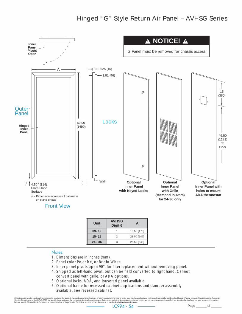
ClimateMaster works continually to improve its products. As a result, the design and specifi cations of each product at the time of order may be changed without notice and may not be as described herein. Please contact ClimateMaster's Customer Service Department at 1-405-745-6000 for specifi c information on the current design and specifi cations. Statements and other information contained herein are not express warranties and do not form the basis of any bargain between the parties, but are merely ClimateMaster's opinion or commendation of its products. The latest version of this document is available at climatemaster.com.
Page ______ of ______LC994 - 54
Notes:1. Dimensions are in inches (mm).2. Panel color Polar Ice, or Bright White3. Inner panel pivots open 90°, for fi lter replacement without removing panel.4. Shipped as left-hand pivot, but can be fi eld converted to right hand. Cannot
convert panel with grille, or ADA options.5. Optional locks, ADA, and louvered panel available.6. Optional frame for recessed cabinet applications and damper assembly
available. See recessed cabinet.
Unit AVHSG Digit 6 A
09- 12 1 18.50 [470]
15- 18 2 21.50 [546]
24 - 36 3 25.50 [648]
Hinged “G” Style Return Air Panel – AVHSG Series
A
59.00(1499)
.625 (16)
1.81 (46)
Wall4.50* (114)From FloorSurface
* - Dimension increases if cabinet is on stand or pad
Front View
HingedInnerPanel
Locks
InnerPanelPivotsOpen
OuterPanel
Optional Inner Panel
with Keyed Locks
Optional Inner Panel with Grille
(stamped louvers)for 24-36 only
15(380)
46.50(1181)
To Floor
Optional Inner Panel with holes to mount ADA thermostat
NOTICE! G Panel must be removed for chassis access
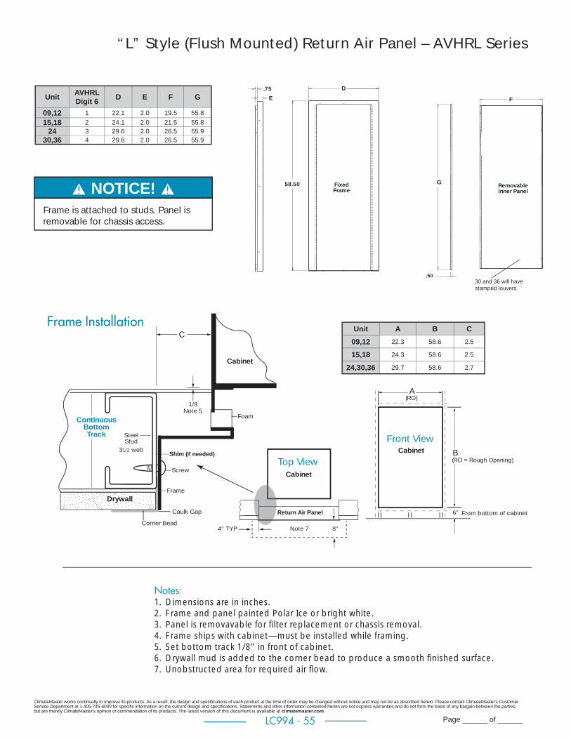
ClimateMaster works continually to improve its products. As a result, the design and specifi cations of each product at the time of order may be changed without notice and may not be as described herein. Please contact ClimateMaster's Customer Service Department at 1-405-745-6000 for specifi c information on the current design and specifi cations. Statements and other information contained herein are not express warranties and do not form the basis of any bargain between the parties, but are merely ClimateMaster's opinion or commendation of its products. The latest version of this document is available at climatemaster.com.
Page ______ of ______LC994 - 55
Notes:1. Dimensions are in inches.2. Frame and panel painted Polar Ice or bright white.3. Panel is removavable for fi lter replacement or chassis removal.4. Frame ships with cabinet—must be installed while framing.5. Set bottom track 1/8" in front of cabinet.6. Drywall mud is added to the corner bead to produce a smooth fi nished surface.7. Unobstructed area for required air fl ow.
“L” Style (Flush Mounted) Return Air Panel – AVHRL Series
RemovableInner Panel
FixedFrame
D
58.50
.75F
G
.50
E
Return Air Panel
Cabinet
Cabinet
CabinetTop View
Front ViewShim (if needed)
Screw
4” TYP 8”
From bottom of cabinet
6”
A
C
(RO)
(RO = Rough Opening)B
SteelStud
31/2 web
ContinuousBottom Track
Foam
Frame
Note 7
Note 5
Corner Bead
Caulk Gap
1/8
Drywall
Frame Installation
NOTICE! Frame is attached to studs. Panel is removable for chassis access.
Unit AVHRL Digit 6 D E F G
09,12 1 22.1 2.0 19.5 55.815,18 2 24.1 2.0 21.5 55.8
24 3 29.6 2.0 26.5 55.930,36 4 29.6 2.0 26.5 55.9
Unit A B C09,12 22.3 58.6 2.5
15,18 24.3 58.6 2.5
24,30,36 29.7 58.6 2.7
30 and 36 will have stamped louvers.
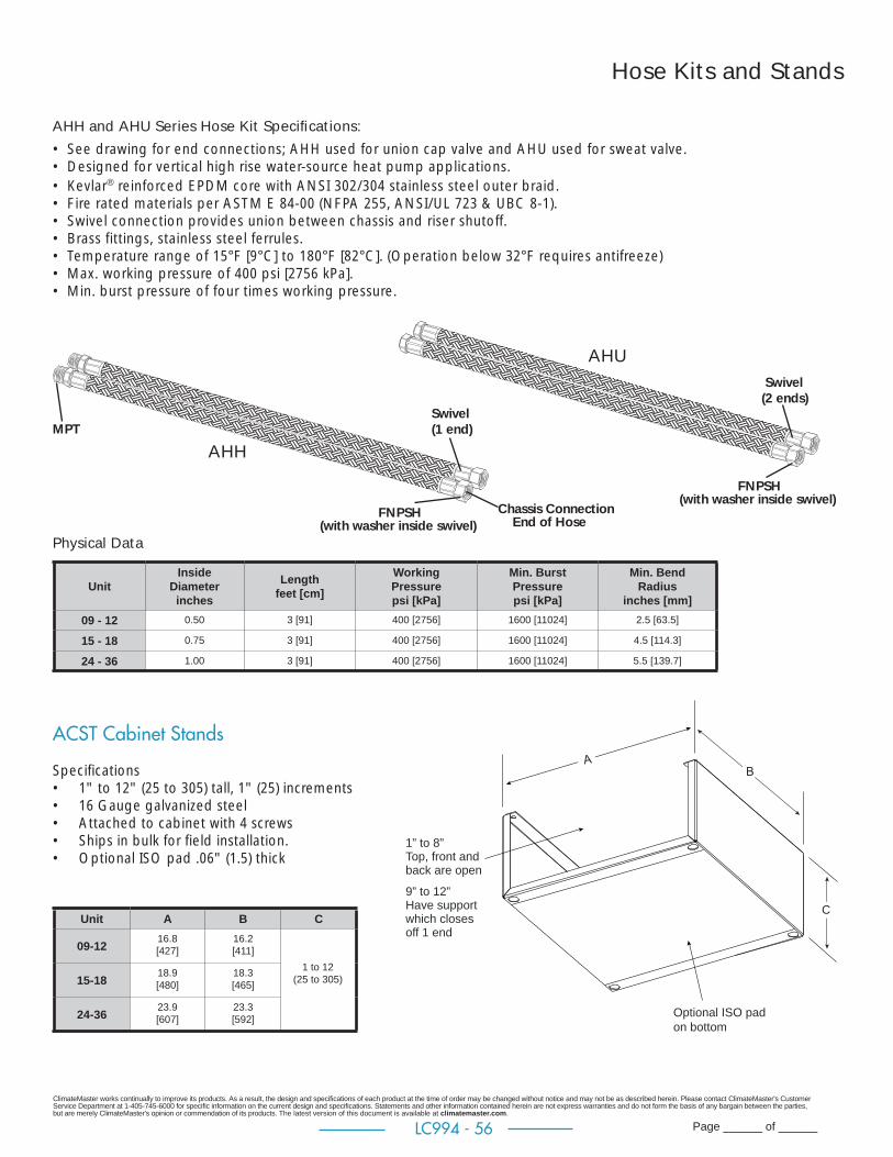
ClimateMaster works continually to improve its products. As a result, the design and specifi cations of each product at the time of order may be changed without notice and may not be as described herein. Please contact ClimateMaster's Customer Service Department at 1-405-745-6000 for specifi c information on the current design and specifi cations. Statements and other information contained herein are not express warranties and do not form the basis of any bargain between the parties, but are merely ClimateMaster's opinion or commendation of its products. The latest version of this document is available at climatemaster.com.
Page ______ of ______LC994 - 56
AHH and AHU Series Hose Kit Specifi cations:• See drawing for end connections; AHH used for union cap valve and AHU used for sweat valve.• Designed for vertical high rise water-source heat pump applications.• Kevlar® reinforced EPDM core with ANSI 302/304 stainless steel outer braid.• Fire rated materials per ASTM E 84-00 (NFPA 255, ANSI/UL 723 & UBC 8-1).• Swivel connection provides union between chassis and riser shutoff.• Brass fittings, stainless steel ferrules.• Temperature range of 15°F [9°C] to 180°F [82°C]. (Operation below 32°F requires antifreeze)• Max. working pressure of 400 psi [2756 kPa].• Min. burst pressure of four times working pressure.
Physical Data
UnitInside
Diameterinches
Lengthfeet [cm]
WorkingPressurepsi [kPa]
Min. BurstPressurepsi [kPa]
Min. BendRadius
inches [mm]09 - 12 0.50 3 [91] 400 [2756] 1600 [11024] 2.5 [63.5]
15 - 18 0.75 3 [91] 400 [2756] 1600 [11024] 4.5 [114.3]
24 - 36 1.00 3 [91] 400 [2756] 1600 [11024] 5.5 [139.7]
Hose Kits and Stands
Optional ISO pad on bottom
1” to 8” Top, front and back are open
9” to 12” Have supportwhich closes off 1 end
C
ACST Cabinet Stands
Specifi cations• 1" to 12" (25 to 305) tall, 1" (25) increments• 16 Gauge galvanized steel• Attached to cabinet with 4 screws• Ships in bulk for field installation.• Optional ISO pad .06" (1.5) thick
Unit A B C
09-12 16.8[427]
16.2[411]
15-18 18.9[480]
18.3[465]
24-36 23.9[607]
23.3[592]
1 to 12(25 to 305)
MPT
AHH
AHU Swivel(2 ends)
Swivel (1 end)
FNPSH(with washer inside swivel)
FNPSH(with washer inside swivel)
Chassis Connection End of Hose
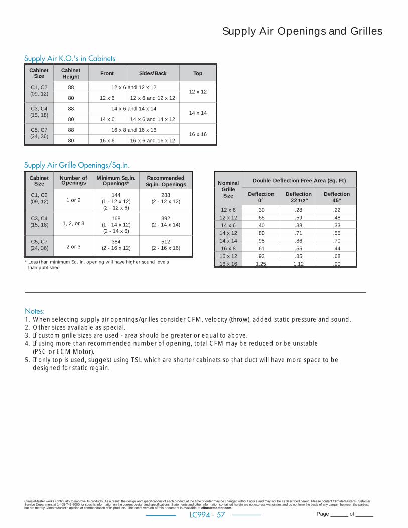
ClimateMaster works continually to improve its products. As a result, the design and specifi cations of each product at the time of order may be changed without notice and may not be as described herein. Please contact ClimateMaster's Customer Service Department at 1-405-745-6000 for specifi c information on the current design and specifi cations. Statements and other information contained herein are not express warranties and do not form the basis of any bargain between the parties, but are merely ClimateMaster's opinion or commendation of its products. The latest version of this document is available at climatemaster.com.
Page ______ of ______LC994 - 57
Supply Air Openings and Grilles
Supply Air K.O.'s in Cabinets
Supply Air Grille Openings/Sq.In.
Nominal Grille Size
Double Defl ection Free Area (Sq. Ft)
Defl ection0°
Defl ection 22 1/2 °
Defl ection45°
12 x 6 .30 .28 .2212 x 12 .65 .59 .4814 x 6 .40 .38 .3314 x 12 .80 .71 .5514 x 14 .95 .86 .7016 x 8 .61 .55 .4416 x 12 .93 .85 .6816 x 16 1.25 1.12 .90
Notes:1. When selecting supply air openings/grilles consider CFM, velocity (throw), added static pressure and sound.2. Other sizes available as special.3. If custom grille sizes are used - area should be greater or equal to above.4. If using more than recommended number of opening, total CFM may be reduced or be unstable
(PSC or ECM Motor).5. If only top is used, suggest using TSL which are shorter cabinets so that duct will have more space to be
designed for static regain.
CabinetSize
Cabinet Height Front Sides/Back Top
C1, C2 (09, 12)
88 12 x 6 and 12 x 1212 x 12
80 12 x 6 12 x 6 and 12 x 12
C3, C4 (15, 18)
88 14 x 6 and 14 x 1414 x 14
80 14 x 6 14 x 6 and 14 x 12
C5, C7 (24, 36)
88 16 x 8 and 16 x 1616 x 16
80 16 x 6 16 x 6 and 16 x 12
CabinetSize
Number of Openings
Minimum Sq.in. Openings*
Recommended Sq.in. Openings
C1, C2 (09, 12) 1 or 2
144(1 - 12 x 12)(2 - 12 x 6)
288(2 - 12 x 12)
C3, C4 (15, 18) 1, 2, or 3
168(1 - 14 x 12)(2 - 14 x 6)
392(2 - 14 x 14)
C5, C7 (24, 36) 2 or 3
384(2 - 16 x 12)
512(2 - 16 x 16)
* Less than minimum Sq. In. opening will have higher sound levels than published
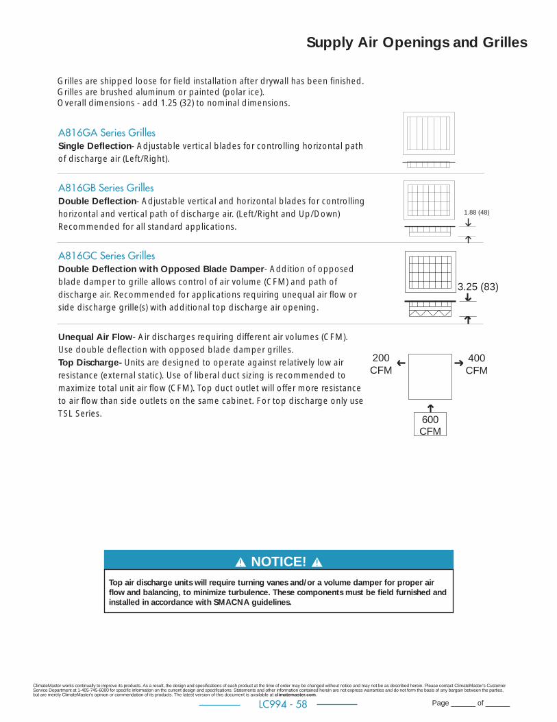
ClimateMaster works continually to improve its products. As a result, the design and specifi cations of each product at the time of order may be changed without notice and may not be as described herein. Please contact ClimateMaster's Customer Service Department at 1-405-745-6000 for specifi c information on the current design and specifi cations. Statements and other information contained herein are not express warranties and do not form the basis of any bargain between the parties, but are merely ClimateMaster's opinion or commendation of its products. The latest version of this document is available at climatemaster.com.
Page ______ of ______LC994 - 58
A816GA Series Grilles Single Defl ection- Adjustable vertical blades for controlling horizontal path of discharge air (Left/Right).
A816GB Series GrillesDouble Defl ection- Adjustable vertical and horizontal blades for controlling horizontal and vertical path of discharge air. (Left/Right and Up/Down)Recommended for all standard applications.
A816GC Series Grilles Double Defl ection with Opposed Blade Damper- Addition of opposed blade damper to grille allows control of air volume (CFM) and path of discharge air. Recommended for applications requiring unequal air fl ow or side discharge grille(s) with additional top discharge air opening.
Unequal Air Flow- Air discharges requiring different air volumes (CFM). Use double defl ection with opposed blade damper grilles.Top Discharge- Units are designed to operate against relatively low air resistance (external static). Use of liberal duct sizing is recommended to maximize total unit air fl ow (CFM). Top duct outlet will offer more resistance to air fl ow than side outlets on the same cabinet. For top discharge only use TSL Series.
Grilles are shipped loose for fi eld installation after drywall has been fi nished.Grilles are brushed aluminum or painted (polar ice).Overall dimensions - add 1.25 (32) to nominal dimensions.
1.88 (48)
400CFM
3.25 (83)
600CFM
200CFM
NOTICE! Top air discharge units will require turning vanes and/or a volume damper for proper air fl ow and balancing, to minimize turbulence. These components must be fi eld furnished and installed in accordance with SMACNA guidelines.
Supply Air Openings and Grilles

ClimateMaster works continually to improve its products. As a result, the design and specifi cations of each product at the time of order may be changed without notice and may not be as described herein. Please contact ClimateMaster's Customer Service Department at 1-405-745-6000 for specifi c information on the current design and specifi cations. Statements and other information contained herein are not express warranties and do not form the basis of any bargain between the parties, but are merely ClimateMaster's opinion or commendation of its products. The latest version of this document is available at climatemaster.com.
Page ______ of ______LC994 - 59
Thermostats
ATC32U02 Thermostat
Wiring:
C
B-R
DXM2-P4
GNDA+B-
24V
A+
A9155805 Thermostat
Wiring:
Compressor
Reversing ValveFan
24Vac Hot24Vac Common
Fault LED
Y1Y2OGRCL
Y
OH
GRC
AL1
DXM2
Molex Connectors
A9155805 Thermostat
Wiring:
Compressor
Reversing ValveFan
24Vac Hot24Vac Common
Fault LED
High Speed
Y1Y2OGRCL
Y
OGRC
AL1
CXM BlowerRelay
Molex Connectors
Thermostat Only
Thermostat
Assembly with
Molex Connector 6”
Pigtail
CX
M
DX
M2
Ma
nu
al C
ha
ng
eo
ver
Au
tom
ati
c C
ha
ng
eo
ver
Pro
gra
mm
ab
le
Dig
ita
l
Fau
lt In
dic
ato
r
Se
tba
ck O
verr
ide
Fan
Sp
ee
ds
Se
t Te
mp
era
ture
Lim
its
Co
mm
un
ica
tin
g
Se
t M
inim
um
Co
olin
g
an
d M
axi
mu
m H
ea
tin
g
ATA11U01 A9155801 X X X X X X 1
ATA11U03 A9155802 X X X X X 2** X X
ATA22U01 A9155804 X X X X X X 1 or 2*
ATP32U03C A9155805 X X X X X X X X 1 or 2* X
ATP21W02A9155809
A9155811X X X X X 1
ATC32U03C A9155806 X X X X X X X 2* X X
*Fan speed change automatic through thermostat Y2 signal.** - Manual speed changeNote: A9155809 for ADA, A9155811 for Remote Mount.
Two types of thermostats are available - AT Series - require fi eld to make wiring connections to screw terminals on thermostat. Cabinet construction for remote thermostat with fi eld supplied whip (wires long enough to reach wall thermostat location) use AT Series.
A91558 Series - are the AT Series thermostats with a wire harness factory assembled, 6” long wires terminating with 9 pin molex connector. Cabinet construction for remote mount thermostat with optional factory whip (15, 25, or 35 foot (457, 762, or 1067 cm) wires terminate with 9 pin molex for quick connection to A91558 Series thermostats.
Customer supplied thermostats should be approved by ClimateMaster Engineering Department prior to using.If heat pump thermostat has W output, do not connect white wire from unit.
All cabinets are compatible with 2 speed thermostats (G2 or Y2).
A9155805 shown below is ATP32U03C with factory wire harness (pigtail) assembled to thermostat.
Note: Order chassis for communicating thermostat or fi eld rewire.

ClimateMaster works continually to improve its products. As a result, the design and specifi cations of each product at the time of order may be changed without notice and may not be as described herein. Please contact ClimateMaster's Customer Service Department at 1-405-745-6000 for specifi c information on the current design and specifi cations. Statements and other information contained herein are not express warranties and do not form the basis of any bargain between the parties, but are merely ClimateMaster's opinion or commendation of its products. The latest version of this document is available at climatemaster.com.
Page ______ of ______LC994 - 60
Optional Cabinet Disconnect Switch (Non Fused)Located on control box access door. Can be accessed through slot in “G” Panel Frame. Classifi ed as motor disconnect. See Cabinet decoder.
Optional Cabinet Circuit Breaker Located on control box access door. Can be accessed through slot in “G” Panel Frame. All 208/230V and 265V 15 and 20 amp classifi ed as HACR breaker. 265V 25 amp and higher classifi ed as supplemental breaker. See Cabinet decoder.
Cabinet Construction for surface-mounted thermostat cabinet has pre-wired 2 x 4 x 1 7/8 deep electric box mounted for horizontal thermostat. Contractor must turn prior to dry walling if fi eld-supplied vertical thermostat is used. Wire harness ends with 9-Pin Molex quick connector for easy connection to A91558 Series thermostats or can be cut off. See Cabinet decoder.
Optional Thermostat Wire Harness (WHIP)Low voltage wire harness 15, 25, or 35 foot ending with 9-Pin Molex quick connector. Exits cabinet on top, left front corner. Thermostat cable is rated CL-2. See Cabinet decoder. Can be encased in BX conduit as special, contact factory.
Optional Premium SealLocated on cabinet fi lter panel, seal is upgraded to extruded rubber gasket for durability and long life.
Optional 2" Filter2" fi lter improves air fi ltration and reduces maintenance.
Accessory Filters (Not available for every application - check blower table for ESP)1" (25mm) thick, MERV 8, and MERV 112" (50mm) thick, MERV 8, MERV 11, MERV 13
TSM Cabinet Options
TSM with ECM Motor Accessory Filter Initial ESP
Model Size Max CFM Max ESPcoil area face velocity Merv 8 Merv 11 Merv 13
sq ft fps 1" 2" 1" 2" 2"C1 9 500 0.25 2.5 200 0.09 0.07 0.10 0.09 0.16
C2 12 500 0.25 2.5 200 0.09 0.07 0.10 0.09 0.16
C3 15 700 0.3 2.5 280 0.17 0.14 0.22 0.15 0.25
C4 18 800 0.3 2.5 320 0.20 0.16 0.29 0.19 0.28
C5 24 950 0.3 3.4 280 0.17 0.14 0.22 0.15 0.25
C6 30 1100 0.4 3.4 325 0.21 0.15 0.32 0.19 0.29
C7 36 1350 0.4 3.4 400 0.26 0.21 0.44 0.24 0.34
Accessory Filter ESP Table
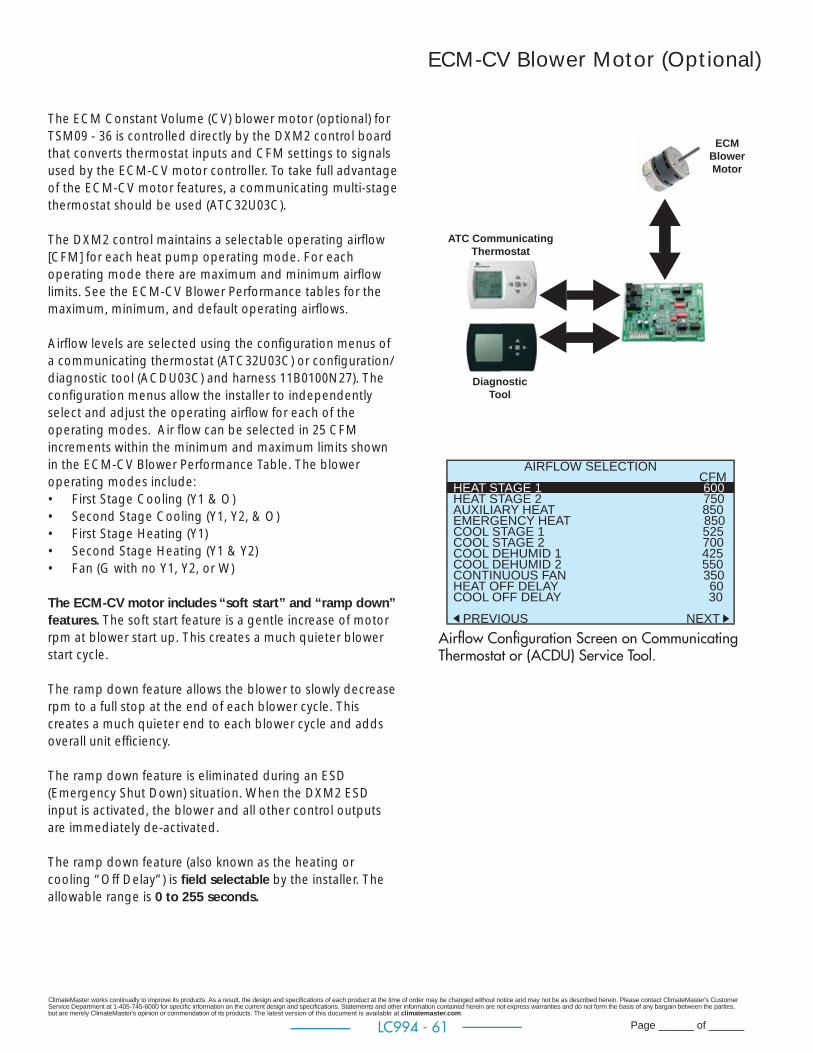
ClimateMaster works continually to improve its products. As a result, the design and specifi cations of each product at the time of order may be changed without notice and may not be as described herein. Please contact ClimateMaster's Customer Service Department at 1-405-745-6000 for specifi c information on the current design and specifi cations. Statements and other information contained herein are not express warranties and do not form the basis of any bargain between the parties, but are merely ClimateMaster's opinion or commendation of its products. The latest version of this document is available at climatemaster.com.
Page ______ of ______LC994 - 61
The ECM Constant Volume (CV) blower motor (optional) for TSM09 - 36 is controlled directly by the DXM2 control board that converts thermostat inputs and CFM settings to signals used by the ECM-CV motor controller. To take full advantage of the ECM-CV motor features, a communicating multi-stage thermostat should be used (ATC32U03C).
The DXM2 control maintains a selectable operating airfl ow [CFM] for each heat pump operating mode. For each operating mode there are maximum and minimum airfl ow limits. See the ECM-CV Blower Performance tables for the maximum, minimum, and default operating airfl ows.
Airfl ow levels are selected using the confi guration menus of a communicating thermostat (ATC32U03C) or confi guration/diagnostic tool (ACDU03C) and harness 11B0100N27). The confi guration menus allow the installer to independently select and adjust the operating airfl ow for each of the operating modes. Air fl ow can be selected in 25 CFM increments within the minimum and maximum limits shown in the ECM-CV Blower Performance Table. The blower operating modes include:• First Stage Cooling (Y1 & O)• Second Stage Cooling (Y1, Y2, & O)• First Stage Heating (Y1)• Second Stage Heating (Y1 & Y2)• Fan (G with no Y1, Y2, or W)
The ECM-CV motor includes “soft start” and “ramp down” features. The soft start feature is a gentle increase of motor rpm at blower start up. This creates a much quieter blower start cycle.
The ramp down feature allows the blower to slowly decrease rpm to a full stop at the end of each blower cycle. This creates a much quieter end to each blower cycle and adds overall unit effi ciency.
The ramp down feature is eliminated during an ESD (Emergency Shut Down) situation. When the DXM2 ESD input is activated, the blower and all other control outputs are immediately de-activated.
The ramp down feature (also known as the heating or cooling “Off Delay”) is fi eld selectable by the installer. The allowable range is 0 to 255 seconds.
AIRFLOW SELECTION CFMHEAT STAGE 1 600HEAT STAGE 2 750 AUXILIARY HEAT 850EMERGENCY HEAT 850COOL STAGE 1 525COOL STAGE 2 700COOL DEHUMID 1 425COOL DEHUMID 2 550CONTINUOUS FAN 350HEAT OFF DELAY 60COOL OFF DELAY 30
PREVIOUS NEXT Airfl ow Confi guration Screen on Communicating Thermostat or (ACDU) Service Tool.
ECM-CV Blower Motor (Optional)
ATC Communicating Thermostat
ECMBlower Motor
Diagnostic Tool

ClimateMaster works continually to improve its products. As a result, the design and specifi cations of each product at the time of order may be changed without notice and may not be as described herein. Please contact ClimateMaster's Customer Service Department at 1-405-745-6000 for specifi c information on the current design and specifi cations. Statements and other information contained herein are not express warranties and do not form the basis of any bargain between the parties, but are merely ClimateMaster's opinion or commendation of its products. The latest version of this document is available at climatemaster.com.
Page ______ of ______LC994 - 62
B Dia.
A Dia.
Standard RiserSwaged 3” DeepFor A Dia. RiserFrom Above
Propress Riser is straight (no swage)
A Dia.
C Dia.
A Dia. A Dia.
3.00(76)6.00
(152)MAX
39.75(1100)
± .50 (13) (Note 10)
3.00(76)
3.12 (79) ± .50 (13)
(Note 10)
B Dia.
Drain RunoutInto Cabinet
Supply and ReturnTransition Up
Supply and ReturnTransition Down
DrainTransition Up
A Dia.
ShutoffValveAssembly
Supply and ReturnStraight
Master Supply and Return Master Drain (Runout Lower)
Drain Only
Top Capped Supply and Return
Top CappedDrain
Bottom CappedSupply and ReturnRunout
for SlaveCabinet Runout
IntoCabinet
RunoutInto
Cabinet
RunoutInto
Cabinet
RunoutInto
CabinetRunout
IntoCabinet (Note 8)
A
A
A
Bottom of Cabinet
Notes:1. You must know water fl ow direction to determine if cabinet requires
transition up or down.2. Transitions can only change by one diameter (1" to 1¼", 1¼" to 1½", etc.)3. Riser transition couplings and runouts are factory brazed.4. All risers are factory pressure tested.5. Standard riser diameters are 1", 1¼", 1½", 2", 2½", 3", and
4"nominal water tubing.6. Copper Type M and L available (4" L only).7. Drain riser insulated standard. Insulation is optional for supply and return8. Master riser - contractor provides tubing from runout to slave cabinet
if needed and brazes shutoff for slave.9. Union shutoff has FPT for AHH hose. Brazed shutoff has NPSH threads
for AHU hose (1/2" for C1 (09), C2 (12); 3/4" for C3 (15), C4 (18); or 1" for C5 (24), C6 (30), C7 (36).
10. If cabinet stand or thick ISO pad is used, at installation add height/thickness to shutoff valve and drain runout height. Verify riser shutoff height with plans before brazing.
Riser Defi nitions
Note: ClimateMaster units with motorized valve option have water high pressure switches. Do not design riser stack where switch will not reset (trip - 300 PSI; Reset - 250 PSI).
Riser Diameter (in)A 1.00 1.25 1.50 2.00 2.50 3.00 4.00
B 1.25 1.50 2.00 2.50 3.00 - -
C - 1.00 1.25 1.50 2.00 2.50 -
HOSE END NPSH THREAD
RISER ENDSWEAT
HOSEEND
O-RING TAIL PIECE UNION
NUT
Sweat Valve(Cabinet Digit 10 = 5)
Used with AHU Style Hoses
Union Valve(Cabinet Digit 10 = 4)
Used with AHH Style Hoses

ClimateMaster works continually to improve its products. As a result, the design and specifi cations of each product at the time of order may be changed without notice and may not be as described herein. Please contact ClimateMaster's Customer Service Department at 1-405-745-6000 for specifi c information on the current design and specifi cations. Statements and other information contained herein are not express warranties and do not form the basis of any bargain between the parties, but are merely ClimateMaster's opinion or commendation of its products. The latest version of this document is available at climatemaster.com.
Page ______ of ______LC994 - 63
Riser GPM Defi nitions and Sizing
Riser GPM requirements and individual Unit GPM requirements are necessary to select the proper Riser Piping diameters. Refer to this page to determine GPM requirement, then refer to Riser Diameter Sizing Table to determine Riser Piping diameters.
Example is for bottom supply (upward fl ow) - bottom return (downward fl ow) system feed loop, both supply and return will be same GPM. GPM's are dependent upon unit load and system loop water temperatures. Please refer to Performance Charts for individual Unit GPM requirements.
Unit GPM (UGPM) = Required gallons per minute from "Performance Charts,"or GPM used to calculate unit capacity.Note: For factory installed AFR check Flow Rate available (See Table)
Total Riser GPM (TRGPM) = The total GPM's required for all units oneach riser.
Total GPM Per Floor (TGF) = Total GPM minus the sum of Unit GPM from all fl oors above or below, depending on direction of fl ow.
Example: Four fl oors, Consisting of units sizes TSM36, TSM24, TSM12 and TSM09, as shown in diagram. UGPM's are 9.0, 6.0, 3.0 and 2.0 respectively.
TRGPM = 9.0 + 6.0 + 3.0 + 2.0 = 20 GPM.
Upward Flow:Floor 1: TGF = 20 Add all fl oor GPM's (TRGPM).Floor 2: TGF = 11 Total GPM minus fl oor 1 GPM.Floor 3: TGF = 5 Total GPM minus fl oors 1 and 2 GPM's.Floor 4: TGF = 2 Total GPM minus fl oors 1, 2, and 3 GPM's.
Downward Flow:Floor 4: TGF = 20 Add all fl oor GPM's (TRGPM).Floor 3: TGF = 18 Total GPM minus fl oor 4 GPM.Floor 2: TGF = 15 Total GPM minus fl oors 1 and 2 GPM's.Floor 1: TGF = 9 Total GPM minus fl oors 1, 2, and 3 GPM's.
Floor 4TSM092.0 GPM
Floor 3TSM123.0 GPM
Floor 2TSM246.0 GPM
Floor 1TSM369.0 GPM
Auto-Flow Regulator (US GPM) Code5/8 Sweat 7/8 SWEAT
Unit 09
Unit 12
Unit 15
Unit 18
Unit 24
Unit 30
Unit 36
C 1.5 – – – – – –
D 2.0 2.0 – – – – –
E 2.5 2.5 2.5 – – – –
F 3.0 3.0 3.0 3.0 – – –
G – 3.5 3.5 3.5 – – –
H – – 4.0 4.0 4.0 – –
J – – – 5.0 5.0 5.0 –
K – – – – 6.0 6.0 6.0
L – – – – 7.0 7.0 7.0
M – – – – – 8.0 8.0
N – – – – – – 9.0
P – – – – – – 10.0
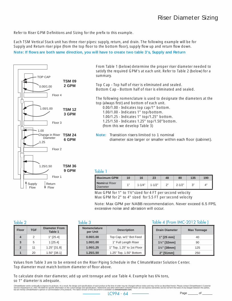
ClimateMaster works continually to improve its products. As a result, the design and specifi cations of each product at the time of order may be changed without notice and may not be as described herein. Please contact ClimateMaster's Customer Service Department at 1-405-745-6000 for specifi c information on the current design and specifi cations. Statements and other information contained herein are not express warranties and do not form the basis of any bargain between the parties, but are merely ClimateMaster's opinion or commendation of its products. The latest version of this document is available at climatemaster.com.
Page ______ of ______LC994 - 64
Riser Diameter Sizing
Refer to Riser GPM Defi nitions and Sizing for the prefi x to this example.
Each TSM Vertical Stack unit has three riser pipes: supply, return, and drain. The following example will be for Supply and Return riser pipe (from the top fl oor to the bottom fl oor), supply fl ow up and return fl ow down.
From Table 1 (below) determine the proper riser diameter needed to satisfy the required GPM's at each unit. Refer to Table 2 (below) for a summary.
Top Cap - Top half of riser is eliminated and sealed.Bottom Cap - Bottom half of riser is eliminated and sealed.
The following nomenclature is used to designate the diameters at the top (always fi rst) and bottom of each unit.
0.00/1.00 - Indicates top cap/1" bottom.1.00/1.00 - Indicates 1" top/bottom.1.00/1.25 - Indicates 1" top/1.25" bottom. 1.25/1.50 - Indicates 1.25" top/1.50"bottom.(from this we develop Table 3)
Note: Transition risers limited to 1 nominal diameter size larger or smaller within each fl oor (cabinet).
TOP CAP
0.00/1.00
1.00/1.00
1.25/1.50
Change in RiserDiameter
Floor 4
Floor 3
Floor 2
Floor 1
SupplyFlow
ReturnFlow
1.00
1.25
TSM 092 GPM
TSM 123 GPM
TSM 246 GPM
TSM 369 GPM
Values from Table 3 are to be entered on the Riser Piping Schedule in the ClimateMaster Solution Center. Top diameter must match bottom diameter of fl oor above.
To calculate drain riser diameter, add up unit tonnage and use Table 4. Example has 6¾ tons, so 1" diameter is adequate.
Table 1
Table 2 Table 3
Floor TGF Diameter From Table 1
4 2 1” [25.4]
3 5 1 [25.4]
2 11 1.25” [31.8]
1 20 1.50” [38.1]
Nomenclatureper Unit Description
0.00/1.00 Top Cap, w/1” Bot Feed
1.00/1.00 1” Full Length Riser
1.00/1.25 1” Top, 1.25” to 1st Floor
1.25/1.50 1.25” Top, 1.50" Bottom
Maximum GPM 10 16 23 48 80 135 190Nominal Riser Diameter 1” 1-1/4” 1-1/2” 2” 2-1/2” 3” 4"
Table 4 (From IMC-2012 Table )
Drain Diameter Max Tonnage
1" [25 mm] 40
1¼" [32mm] 90
1½" [38mm] 125
2" [51mm] 250
Note: Max GPM per NABB recommendation. Never exceed 6.5 FPS, excessive noise and abrasion will occur.
Note: If fl ows are both same direction, you will have to create two table 3's, Supply and Return
Max GPM for 1" to 1½"sized for 4 FT per second velocityMax GPM for 2" to 4" sized for 5.5 FT per second velocity

ClimateMaster works continually to improve its products. As a result, the design and specifi cations of each product at the time of order may be changed without notice and may not be as described herein. Please contact ClimateMaster's Customer Service Department at 1-405-745-6000 for specifi c information on the current design and specifi cations. Statements and other information contained herein are not express warranties and do not form the basis of any bargain between the parties, but are merely ClimateMaster's opinion or commendation of its products. The latest version of this document is available at climatemaster.com.
Page ______ of ______LC994 - 65
Swage Riser Length Defi nitions and Sizing
Total Riser Length (L) for same height cabinets on every fl oor = FF of fl oor below + 2"(51)
Note - If cabinet heights are mixed then L must be calculated. (88", 80",or 65")
Floor To Floor Height (FF): Distance from top of unit slab to top of above slab.
Room Riser Height (RRH): Cabinet height + 3" (76).
Riser Tail Piece (RT): Length of riser extending down from the cabinet. Riser tail piece must extend a minimum of 5" (127) below slab.
Slab thickness (ST); Slab thickness plus and additional material added to slab prior to setting cabinets.
Riser insertion into swage = 2" (51)
Example 1 - Calculating Riser Length
SECOND FLOOR RISER LENGTH Slab = 8" (203) Cabinet Height = 88" (2235)
Use FF from fi rst fl oor L = FF + 2"(50) = 106 (2692) RRH = 91 (2311) RT = 15 (381)
THIRD FLOOR RISER LENGTH Use FF from second fl oor L = 112 (2844) RRH = 91 (2311) RT = 21 (533)
FF=110 (2794)
FF=104 (2642)
8” (203) SLAB
All Floors
BASEMENT
FIRST FLOOR
SECOND FLOOR
THIRD FLOOR
RT
88”
88”
88”
RRH=91 (2311)
RRH=91 (2311)
L=112 (2844)
L=106 (2692)
L=120 MAX (3048)
CH = 102 (2591)
8 (203)
8 (203)FIRST
FLOOR
SECOND FLOOR
TYPE 2Drop In
Riser Length
106 (2692)
Notes:1. Always use bottom of cabinet for calculations. If optional stand is used, everything raises dimension of stand.2. If riser maximum 120 (3048) is exceeded or RT is less than slab + 5" (127) must use extension, see riser extension sizing.3. Complete all core drilling before setting cabinets, openings must be aligned and plumb.4. Set from lowest fl oor up.5. If risers are shipped separate they are bulk shipped. Can palletize risers by fl oor as special.6. Secure riser stack to building structure and use expansion fi ttings as required.7. For calculating and entering on Solution Center, use full length even if top or bottom is capped.8. Dimensions are inches (mm).
Example 2 - Checking Lengthfor drop in to confi rm acceptable
L = 106 (2591) TYPE 2 drop in Slab Slot = See slab slot chart for width and length.
Clear Height (CH) and Riser Length (L) are used to determine slab slot dimensions so riser will pass through slot without hitting ceiling.
CH = FF - ST
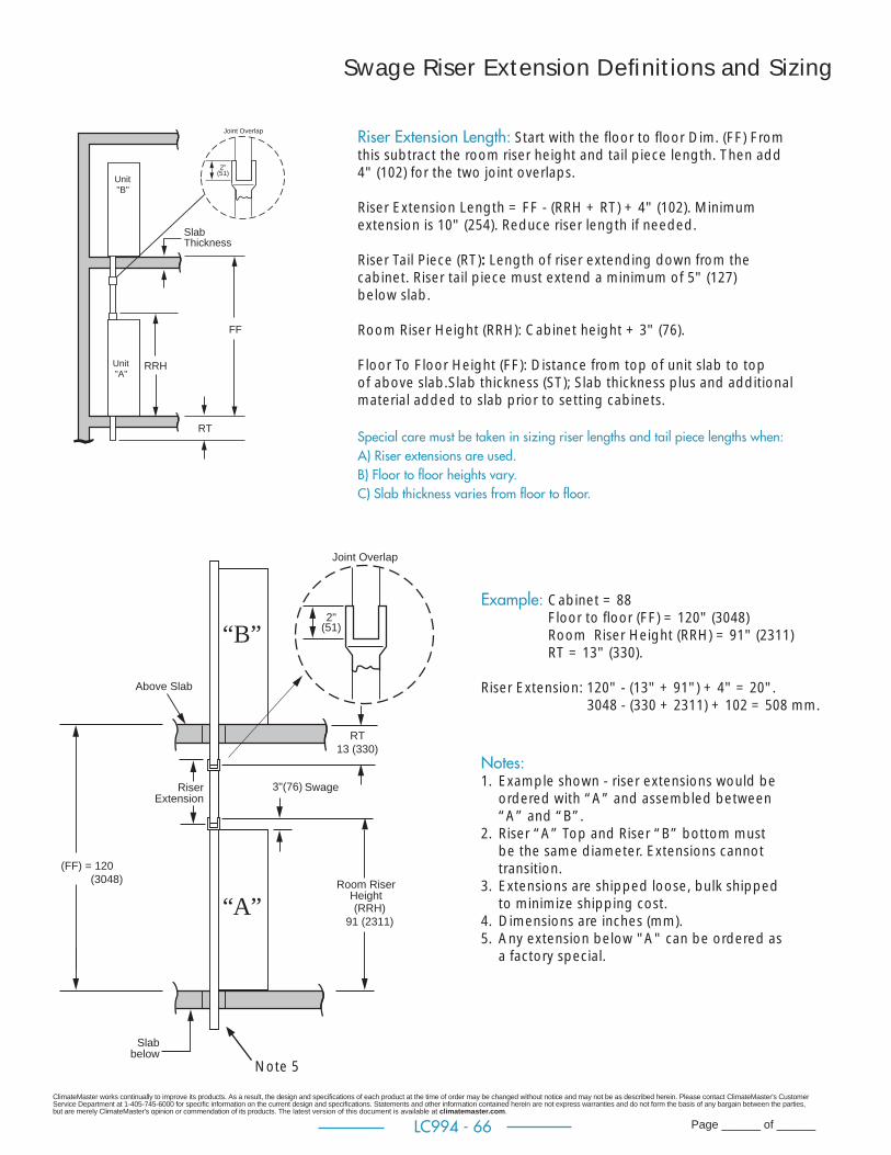
ClimateMaster works continually to improve its products. As a result, the design and specifi cations of each product at the time of order may be changed without notice and may not be as described herein. Please contact ClimateMaster's Customer Service Department at 1-405-745-6000 for specifi c information on the current design and specifi cations. Statements and other information contained herein are not express warranties and do not form the basis of any bargain between the parties, but are merely ClimateMaster's opinion or commendation of its products. The latest version of this document is available at climatemaster.com.
Page ______ of ______LC994 - 66
Swage Riser Extension Defi nitions and Sizing
Riser Extension Length: Start with the fl oor to fl oor Dim. (FF) From this subtract the room riser height and tail piece length. Then add 4" (102) for the two joint overlaps.
Riser Extension Length = FF - (RRH + RT) + 4" (102). Minimum extension is 10" (254). Reduce riser length if needed.
Riser Tail Piece (RT): Length of riser extending down from the cabinet. Riser tail piece must extend a minimum of 5" (127) below slab.
Room Riser Height (RRH): Cabinet height + 3" (76).
Floor To Floor Height (FF): Distance from top of unit slab to top of above slab.Slab thickness (ST); Slab thickness plus and additional material added to slab prior to setting cabinets.
Special care must be taken in sizing riser lengths and tail piece lengths when:A) Riser extensions are used.B) Floor to fl oor heights vary.C) Slab thickness varies from fl oor to fl oor.
3"(76)
2"(51)
Room RiserHeight(RRH)
91 (2311)
Joint Overlap
RiserExtension
Above Slab
Slabbelow
(FF) = 120 (3048)
Swage
“A”
“B”
RT 13 (330)
Notes:1. Example shown - riser extensions would be
ordered with “A” and assembled between “A” and “B”.
2. Riser “A” Top and Riser “B” bottom must be the same diameter. Extensions cannot transition.
3. Extensions are shipped loose, bulk shipped to minimize shipping cost.
4. Dimensions are inches (mm).5. Any extension below "A" can be ordered as
a factory special.
Example: Cabinet = 88 Floor to fl oor (FF) = 120" (3048) Room Riser Height (RRH) = 91" (2311) RT = 13" (330).
Riser Extension: 120" - (13" + 91") + 4" = 20". 3048 - (330 + 2311) + 102 = 508 mm.
SlabThickness
FF
RT
RRH
Unit"B"
Unit"A"
2"(51)
Joint Overlap
Note 5
ClimateMaster works continually to improve its products. As a result, the design and specifi cations of each product at the time of order may be changed without notice and may not be as described herein. Please contact ClimateMaster's Customer Service Department at 1-405-745-6000 for specifi c information on the current design and specifi cations. Statements and other information contained herein are not express warranties and do not form the basis of any bargain between the parties, but are merely ClimateMaster's opinion or commendation of its products. The latest version of this document is available at climatemaster.com.
Page ______ of ______LC994 - 67
Setting Cabinet
To determine the slab slot size required for the risers and to determine if clear height is OK for unit installation, use the example 2 on riser length page and slab slot charts on the next page.
Type 1 Single UnitsWith a minimum clear height of 93" (2362). Start with the riser side down, lift and insert risers into slot, rotate upward, slowly pass risers through slot, set cabinet on fl oor.
Type 2 Single Units With a minimum clear height of 95" (2413). Start with the side opposite of the risers down, lift and insert risers into slot, rotate upward, slowly pass risers through slot, set cabinet on fl oor.
Type 3 Single UnitsWith a minimum clear height of 94" (2388). Start with the risers on eitherside, lift and insert risers into slot, rotate upward, slowly pass risers through slot, set cabinet on fl oor.
NOTICE! Before locating riser slab slot in fl oor, review plans and all information in this submittal regarding cabinet, risers, slab slot, rotation into slot, clear height and the relationship of all.
Rotating Cabinet with Risers Into Position
CH
To use the charts you will need the clear height of the room the unit is in, riser length, diameter, and type of installation. (See below)

ClimateMaster works continually to improve its products. As a result, the design and specifi cations of each product at the time of order may be changed without notice and may not be as described herein. Please contact ClimateMaster's Customer Service Department at 1-405-745-6000 for specifi c information on the current design and specifi cations. Statements and other information contained herein are not express warranties and do not form the basis of any bargain between the parties, but are merely ClimateMaster's opinion or commendation of its products. The latest version of this document is available at climatemaster.com.
Page ______ of ______LC994 - 68
Slab Slot Chart - 3 Pipe
Type of Installing Cabinet Through Slot
Model Clear Height Riser length Type 1 Type 2 Type 3
09-18
in mm in mm in mm in mm in mm105 2667 115 2921
8 x 13 1/2 203 x343
6 1/2 x 13 1/2 165 x 3436 1/2 x 16 165 x 406
100 2540 110 279498 2498 108 274396 2438 106 269295 2413 105 2667
94 2387 104 2641 no93 2362 103 2616 no no
24-36
105 2667 115 2921
9 x 13 1/2 229 x 343
7 1/2 x 13 1/2 190 x 343
6 1/2 x 16 1/2 165 x 419
100 2540 110 279496 2498 108 2743
95 2413 105 2667 no94 2387 104 2641 no93 2362 103 2616 no no
Chart dimensions for 3”(76.2) supply and return risers with insulation and 2” drain riser, 88” (2235)cabinet, and 8”(203) slabClear height is dimension from fl oor to ceiling. Riser length is clear height plus slab thickness plus 2” (50).For 2” (50.8)risers setting by any Type 1,2, or 3 reduce width by 1” (25) also Type 3 reduce length by 1” (25)For 1” (25.4) risers setting by any Type 1,2, or 3 reduce width by 2” (50) also Type 3 reduce length by 2” (50)Opening centerline must be aligned from fl oor to fl oorContractor is responsible to meet all codes and regulations.
Slab Slot for Cabinets with Risers
Riser Stack Patterns
S SR RD D
9¼
W
L
For Cabinet Styles 2 and 5 For Cabinet Styles 3 and 4
Clear Height is Floor to Ceiling Dimension
Riser Diameter
ModelClear Height Riser Length 3 76.2 2 50.8 1 25.4
in mm in mm in mm in mm in mm
All
105 2667 115 2921
6 1/2 165 5 1/2 140 4 1/2 114
100 2540 110 2794
96 2438 106 2692
95 2413 105 2667
94 2387 104 2641
93 2362 103 2616
Dimensions for 8” (203) slabClear height is dimension from fl oor to ceiling. Riser length is clear height plus slab thickness plus 2” (50).Opening centerline must be aligned from fl oor to fl oorFor risers over 100” (2540) using extensions with clear height equal to riser length or more, the hole size can be riser diameter plus 1” (25mm). If riser diameter is not shown use next larger size.Contractor is responsible to meet all codes and regulations.
Slab Hole if Risers Ship Loose and Installed Before Cabinet
ClimateMaster works continually to improve its products. As a result, the design and specifi cations of each product at the time of order may be changed without notice and may not be as described herein. Please contact ClimateMaster's Customer Service Department at 1-405-745-6000 for specifi c information on the current design and specifi cations. Statements and other information contained herein are not express warranties and do not form the basis of any bargain between the parties, but are merely ClimateMaster's opinion or commendation of its products. The latest version of this document is available at climatemaster.com.
Page ______ of ______LC994 - 69
Units Are Shipped FOB FactoryTSM Chassis can be shipped 2 ways. 1. Upright in carton 4 per pallet, see fi gure 1. 2. Upright inside cabinet (risers shipped separate or customer supplied) 4 per pallet, see fi gure 1.
TSM Cabinet without risers attached can ship upright 4 per pallet, see fi gure 1.
TSM Cabinet with risers attached must be shipped horizontal and normally on dedicated open fl at bed trailer either 3 or 6 per pallet, see fi gure 2 and 3. Cabinets are palletized to maximize shipping density then grouped by unit size, building, and fl oor where possible. Pallets are shrink wrapped and fl at bed load is tarped for protection.Special shipping accommodations can be provided. Request added cost before quoting job, shipping cost could increase signifi cantly and any additional charges will be billed. Some examples include, end fork pallets, reduced number of units per pallet, palletized specifi cally by riser, by fl oor, or over crating.
Figure 1
Shipping
Forkthisside
H
LW
Vertical Shipping
DescriptionPer 4 pack on pallet Aprox. Quantity Per
53 foot Box Trailer
Approximate Weight per
palletLength Width Height
Chassis 09-18 40 40 50 120 single stacked 500 lbsChassis 24-36 50 48 52 96 single stacked 750 lbsChassis 09-18 40 40 100 240 double stacked 500 lbsChassis 24-36 50 48 104 192 double stacked 750 lbs
Slave cabinet 09-18 43 43 85/93 112 single stacked 450 lbsSlave cabinet 24-36 53 53 85/93 72 single stacked 700 lbs
Cabinet with Chassis 09-18 43 43 85/93 112 single stacked 960 lbsCabinet with Chassis 24-36 53 53 85/93 72 single stacked 1450 lbs
Shipping Height 85" for 80" cabinet and 93" for 88" cabinetSmall and Large cabinets can be mixed on some loads88” Cabinets cannot have stands factory assembled, must ship loose or ship horizontal.
Horizontal Shipping
DescriptionNumber of cabinets per pallet
Pallet Up to 110" Long Riser Aprox. Quantity Per 48
foot open fl at bed Trailer
111" to 120" Long Riser Aprox. Quantity Per 48 foot
open fl at bed Trailer
Approximate Weight Per PalletLength Width Height
Cabinet 09-18
4 * 26 88 60 48 800 lbs
8 * 50 88 60 48 1600 lbs
Cabinet 24-36
3 * 30 87 45 36 800 lbs
6 * 59 87 45 36 1600 lbs
*- For length of pallet add 5” to riser length
H
WL
Fork fromlong side
Figure 3Figure 2
ClimateMaster works continually to improve its products. As a result, the design and specifi cations of each product at the time of order may be changed without notice and may not be as described herein. Please contact ClimateMaster's Customer Service Department at 1-405-745-6000 for specifi c information on the current design and specifi cations. Statements and other information contained herein are not express warranties and do not form the basis of any bargain between the parties, but are merely ClimateMaster's opinion or commendation of its products. The latest version of this document is available at climatemaster.com.
Page ______ of ______LC994 - 70
Tranquility® Vertical Stack TSM Series Engineering Specifi cations – Page 1
General:Furnish and install ClimateMaster Tranquility® “TSM Vertical Stack” Water Source Heat Pumps, as indicated on the plans with
capacities and characteristics as listed in the schedule and the specifi cations that follow.
Units shall be supplied completely factory built capable of operating over an entering water temperature range from 20° to 120°F
(-6.7° to 48.9°C) as standard. Equivalent units from other manufacturers may be proposed provided approval to bid is given 10 days
prior to bid closing. All equipment listed in this section must be rated and certifi ed in accordance with Air-Conditioning, Heating and
Refrigeration Institute/International Standards Organization (AHRI / ISO 13256-1). All equipment must be tested, investigated, and
determined to comply with the requirements of the standards for Heating and Cooling Equipment UL-1995 for the United States and
CAN/CSA-C22.2 NO.236 for Canada, by Intertek Testing Laboratories (ETL). The units shall have AHRI / ISO and ETL-US-C labels.
All units shall pass a factory acceptance test. The quality control system shall automatically perform the factory acceptance test via
computer. A detailed report card from the factory acceptance test shall ship with each unit. (Note: If unit fails the factory acceptance
test it shall not be allowed to ship. Unit serial number will be recorded by factory acceptance test and furnished on report card
for ease of unit warranty status.)
Cabinet Construction:The cabinet panels shall be fabricated from heavy gauge galvanized steel. The rigid one-piece cabinet assembly shall be constructed
so that it is self-supporting, and can be installed prior to the chassis arrival, and to be able to avoid damage during construction.
Top, base, blower deck, and other metal structural parts are to be 16 gauge construction, while exterior panels to be 20 gauge; unit
further strengthened by structural breaks at corners. Units not constructed of a minimum of these thicknesses are not acceptable. Cabinet shall have a full panel over the chassis opening for structural rigidity of the cabinet; no “open” top or “open” bottom designs allowed.
The cabinet base shall contain a secondary drain pan fully insulated with a pressure differential drain trap connected to the condensate
riser pipe, and guide rails for the slide in refrigeration chassis. Drain pan to be rubber grommet mounted to provide isolation of chassis
from the cabinet. Drain pan(s) shall be easily accessible for cleaning. All interior surfaces shall be lined with 1/2 inch (12.7mm) thick,
1-1/2 lb/ft3 (24 kg/m3) acoustic type fi berglass insulation. All insulation shall be foil faced and have exposed edges butted up to
fl anges to prevent the introduction of glass fi bers into the air stream.
Standard insulation must meet NFPA Fire Hazard Classifi cation requirements 25/50 per ASTM E84, UL 723, CAN/ULC S102-M88 and
NFPA 90A requirements; air erosion and mold growth limits of UL-181; stringent fungal resistance test per ASTM-C1071 and ASTM
G21; and shall meet zero level bacteria growth per ASTM G22. Unit insulation must meet these stringent requirements or unit(s) will not be accepted.
Standard is 1 inch (25mm) fi lter holder with 1” (25mm) thick fi berglass throwaway fi lter.
Option: 2 inch (50mm) fi lter holder with 2” (50mm) thick fi berglass throwaway fi lter.
Cabinet arrangements shall allow placement of riser piping on any one of the three sides of the cabinet not used for the chassis access
and air supply. All cabinets shall have supply air knockouts on all sides and top. Return Air K.O. to be removed from panel behind
the fi lter. Field shall confi gure cabinets by removing factory knockouts and install duct fl anges per model confi guration shown on
plans. For air noise attenuation purposes, the discharge air from fan shall discharge into insulated plenum that also contains x-shape
painted air baffl e. Units not having supply air noise baffl es are not acceptable. Cabinet design shall allow a full height base board (4.50
inches/114mm) beneath the return air “G” panel. The cabinet shall contain an easily removable motor/blower assembly.
Option: Factory to confi gure supply air openings, remove K.O., cut insulation, and install duct angles. With dust protection, includes capping supply air openings and leaving K.O. in panel behind fi lter (installer to remove both).

ClimateMaster works continually to improve its products. As a result, the design and specifi cations of each product at the time of order may be changed without notice and may not be as described herein. Please contact ClimateMaster's Customer Service Department at 1-405-745-6000 for specifi c information on the current design and specifi cations. Statements and other information contained herein are not express warranties and do not form the basis of any bargain between the parties, but are merely ClimateMaster's opinion or commendation of its products. The latest version of this document is available at climatemaster.com.
Page ______ of ______LC994 - 71
Electrical conduit shall be installed from electrical unit control compartment to top of cabinet for low voltage control wiring as well as separate conduit for main power wiring. Units without these two factory installed electric conduits will not be accepted.
Option: Master and slave cabinets.
Option: Isolation pad attached to bottom of cabinet for best sound attenuation.
Option: Cabinet height 80” or 88” (203 or 223 cm)
Option: Construction for unit mounted Thermostat (thermostat ordered separate) -- includes junction box mounted outside discharge plenum and has a Molex-type connector inside for quick connection to A91558 Series thermostat. Use part number A9155801, A9155802, A9155810, A9155804, A9155805, or A9155806 thermostat assembly, which is thermostat model ATA11U01, ATA11U03, ATP21W02, ATA22U01, ATP32U03C or ATC32U02C respectively with mating molex-type connector.
Option: Low voltage 15, 25, or 35 foot (572, 762, or 1,067 cm) wire harness (whip) with molex-type connector for connection to remote mounted thermostat. Use A9155801, A9155802, A9155811, A9155804, A9155805, or A9155806 thermostat assembly, which is thermostat model ATA11U01, ATA11U03, ATP21W02, ATA22U01, ATP32U03C or ATC32U02C respectively with mating molex-type connector.
Option: Cabinet to have wire harness for connection to A91558 series thermostat mounted to ADA “G” return air panel.
Option: Premium automotive grade rubber seal between cabinet inner panel and chassis.
Full-length supply, return, and insulated condensate water risers shall be type M copper. Riser length up to 120” (305cm) is standard.
Supply and return risers have integral internal piping including ball valves (for shut off purposes at unit). Risers and piping shall be
factory pressure tested to check for leaks. Field installed hose kits are required to connect the chassis piping to the cabinet ball valve.
The condensate riser shall be insulated with 3/8” (9.5mm) Armafl ex type insulation. The top of each riser shall be deeply swaged (3
in./76.2mm) to accept connection to the riser above/below, allowing for a fl oor to fl oor dimensional variance of ± one inch (25.4mm).
Units not having swaged riser-piping connections shall not be acceptable. Couplings and trim pieces shall not be allowed.
Option: Bulk ship risers so complete riser stack can be installed, pressure tested, and fi lled before the cabinets are installed.
Option: Type L riser piping.
Option: Supply and return risers insulated with 3/8” (9.5mm) ARMAFLEX (closed cell) type insulation. 1" through 3" diameter standard, 4" diameter available. Union style or brazed shutoffs available.
Option: Non-swaged riser piping for crimp (non-brazed) style connections.
Fan and Motor Assembly:The cabinet shall contain a removable motor/blower assembly. Units shall have a direct drive centrifugal fan. The fan motor shall be
3 speed, permanently lubricated, PSC type with thermal overload protection. The fan motor for small size units (09 and 12) shall be
isolated from the fan housing by a torsionally fl exible motor mounting system with rubber type grommets to inhibit vibration induced
high noise levels associated with “hard wire belly band” motor mounting. The fan motor on medium and large units (15-36) shall be
isolated with fl exible rubber type isolation grommets only. Airfl ow/External static pressure rating of the unit shall be based on a wet
coil and clean fi lter. Ratings based on a dry coil and/or no air fi lter shall not be acceptable.
Tranquility® Vertical Stack TSM Series Engineering Specifi cations – Page 2

ClimateMaster works continually to improve its products. As a result, the design and specifi cations of each product at the time of order may be changed without notice and may not be as described herein. Please contact ClimateMaster's Customer Service Department at 1-405-745-6000 for specifi c information on the current design and specifi cations. Statements and other information contained herein are not express warranties and do not form the basis of any bargain between the parties, but are merely ClimateMaster's opinion or commendation of its products. The latest version of this document is available at climatemaster.com.
Page ______ of ______LC994 - 72
Tranquility® Vertical Stack TSM SeriesEngineering Specifi cations – Page3
Option: ECM Constant Volume (CV) variable speed ball bearing type motor. The ECM-CV fan motor shall provide soft starting, maintain constant CFM over its static operating range and provide airfl ow adjustment in 25 CFM increments via its control board. The fan motor shall be isolated from housing by rubber grommets. The motor shall be permanently lubricated and have thermal overload protection. A special dehumidifi cation mode shall be provided to allow lower airfl ows in cooling for better dehumidifi cation. The dehumidifi cation mode may be constant or automatic (humidistat controlled).
Option: ECM Constant Torque (CT). The fan motor shall be isolated from housing by rubber grommets. The motor shall be permanently lubricated and have thermal overload protection.
Chassis:
The chassis, which incorporates the air coil, water coil, drain pan with solid-state electronic condensate overfl ow protection,
compressor, and electrical components shall be easily installed for quick jobsite installation and future servicing purposes. The slide
in chassis shall have insulated panels surrounding the compressor. Compressors are not in the air stream. The chassis base shall be
fabricated from heavy gauge galvanized steel formed to match the slide in rails of the cabinet. Units shall have a factory installed 1
inch (25.4mm) thick fi lter bracket and throwaway type glass fi ber fi lter. Furnish one spare set of fi lters.
Option: Chassis can ship upright in any cabinet that risers are not attached.
Option: UltraQuiet package shall consist of the standard double isolation of the compressor plus sound attenuating compressor blanket applied to the compressor. All sheet metal surrounding the compressor shall have high density sound attenuating material with STC rating of 26 per ASTM E-90 and then covered with fi berglass insulation.
Option: Factory wired for communicating thermostat, requires ATC32U02 thermostat.
Option: Rib relay replaces contactor for models 09 through 18. Eliminates contactor “click” when fi rst energized.
Option: VFLow® The unit will be supplied with internally factory mounted modulating water valve with delta T control. The factory built-in valve shall modulate water fl ow through unit based on a fi eld adjustable water temperature difference between the entering and leaving water. The valve shall automatically adjust for operating mode, source water temperature and variations in external head pressure. The valve will also act as a shut-off valve to prevent water fl ow through the unit when the unit is not activated and will have a minimum position capability.
Water connections between chassis and the cabinet shall be accomplished via a hose kit consisting of Kevlar-reinforced EPDM core
hose surrounded by a stainless-steel braid. Hose kit shall have brass fi ttings with stainless-steel ferrules. AHH hose ends shall be solid
External MPT which connects to mating fi tting on cabinet shut off ball valve(s), and Internal NPSM (National Pipe Straight Mechanical)
swivel end with fi ber or EPDM washer which connects to mating threaded end connection on chassis. AHU hose ends shall be Internal
NPSM (National Pipe Straight Mechanical) swivel end with fi ber or EPDM washer which connects to mating threaded end connection
on chassis. The hose kit shall be rated for 400 psi (2756 kPa) design working pressure.
Refrigerant Circuit: All units shall contain an EarthPure® (HFC-410A) sealed refrigerant circuit including a high effi ciency scroll or rotary compressor
designed for heat pump operation, a thermostatic expansion valve for refrigerant metering, an enhanced corrugated aluminum lanced
fi n and rifl ed copper tube refrigerant to air heat exchanger, reversing valve, coaxial (tube in tube) refrigerant to water heat exchanger,
ClimateMaster works continually to improve its products. As a result, the design and specifi cations of each product at the time of order may be changed without notice and may not be as described herein. Please contact ClimateMaster's Customer Service Department at 1-405-745-6000 for specifi c information on the current design and specifi cations. Statements and other information contained herein are not express warranties and do not form the basis of any bargain between the parties, but are merely ClimateMaster's opinion or commendation of its products. The latest version of this document is available at climatemaster.com.
Page ______ of ______LC994 - 73
Tranquility® Vertical Stack TSM Series Engineering Specifi cations – Page 4
and safety controls including a high pressure switch, low pressure switch (loss of charge), water coil low temperature sensor, and air
coil low temperature sensor. Access fi ttings shall be factory installed on high and low pressure refrigerant lines to facilitate fi eld service.
Activation of any safety device shall prevent compressor operation via a microprocessor lockout circuit. The lockout circuit shall be
reset at the thermostat or at the contractor supplied disconnect switch. Units that cannot be reset at the thermostat shall not be acceptable.
Hermetic compressors shall be internally sprung and externally isolated. The compressor shall have a dual level vibration isolation
system. The compressor will be mounted on specially engineered sound-tested EPDM vibration isolation grommets to a large
heavy gauge compressor base pan, which is then isolated from the cabinet by resting on condensate drain pan which is isolated by
grommets for maximized vibration attenuation. All units (except units with rotary compressors) shall include a discharge muffl er to
further enhance sound attenuation. Compressor shall have thermal overload protection.
Refrigerant to air heat exchangers shall utilize enhanced corrugated lanced aluminum fi ns and rifl ed copper tube construction rated to
withstand 625 PSIG (4309 kPa) refrigerant working pressure. Copper hairpins are tin electroplated for added protection from formicary
corrosion. Units that do not have tin-plated hairpins shall not be acceptable.
Refrigerant to water heat exchangers shall be of copper inner water tube and steel refrigerant outer tube design, rated to withstand
625 PSIG (4309 kPa) working refrigerant pressure and 500 PSIG (3445 kPa) working water pressure. The refrigerant to water heat
exchanger shall be “electro-coated” with a low cure cathodic epoxy material a minimum of 0.4 mils thick (0.4 – 1.5 mils range) on all
surfaces. The black colored coating shall provide a minimum of 1000 hours salt spray protection per ASTM B117-97 on all external
steel and copper tubing. The material shall be formulated without the inclusion of any heavy metals and shall exhibit a pencil hardness
of 2H (ASTM D3363-92A), crosshatch adhesion of 4B-5B (ASTM D3359-95), and impact resistance of 160 in-lbs (184 kg-cm) direct
(ASTM D2794-93).
Refrigerant metering shall be accomplished by thermostatic expansion valve only. Expansion valves shall be dual port balanced types
with external equalizer for optimum refrigerant metering. Units shall be designed and tested for operating ranges of entering water
temperatures from 20° to 120°F (-6.7° to 48.9°C). Reversing valve shall be four-way solenoid activated refrigerant valve, which shall
default to heating mode should the solenoid fail to function. If the reversing valve solenoid defaults to cooling mode, an additional
low temperature thermostat must be provided to prevent over-cooling an already cold room.
Option: The unit will be supplied with non-plated air to refrigerant heat exchanger.
Option: The unit will be supplied with cupro-nickel coaxial water to refrigerant heat exchanger.
Option: The unit will be supplied with internally factory mounted two-way water valve for variable speed loop pumping requirements. Valve to be normally closed type. Water circuit will have factory installed high pressure switch located between MWV and heat exchanger.
Option: The unit will be supplied with internally factory mounted automatic water fl ow regulators.
Option: The unit will be supplied with internally factory mounted secondary pump rated for 200 PSIG.
Option: The unit will be supplied with vFlow® modulating water valve (requires DMX2). The valve will maintain a set Delta T. through the unit. Unit will operate at optimal capacity and effi ciency.
Cabinet Drain Pan:The drain pan shall be constructed of galvanized steel and have a powder coat paint application to further inhibit corrosion. This
corrosion protection system shall meet the stringent 1000 hour salt spray test per ASTM B117. Drain pan to be isolated from cabinet
with four EPDM vibration isolation grommets. If plastic type material is used, it must be HDPE (High Density Polyethylene) to avoid

ClimateMaster works continually to improve its products. As a result, the design and specifi cations of each product at the time of order may be changed without notice and may not be as described herein. Please contact ClimateMaster's Customer Service Department at 1-405-745-6000 for specifi c information on the current design and specifi cations. Statements and other information contained herein are not express warranties and do not form the basis of any bargain between the parties, but are merely ClimateMaster's opinion or commendation of its products. The latest version of this document is available at climatemaster.com.
Page ______ of ______LC994 - 74
Tranquility® Vertical Stack TSM Series Engineering Specifi cations – Page 5
thermal cycling shock stress failure over the lifetime of the unit. Drain pan shall be fully insulated. Drain pan shall have at a minimum a
doubled sloped surface to allow positive drainage to the outlet opening, which shall be at the lowest level of the entire pan surface.
Drain outlet shall be connected from pan outlet to condensate riser (if supplied) with factory installed trap inside of cabinet. The
cabinet drain pan as standard will be supplied with solid-state electronic condensate overfl ow protection. Drain pans that are not isolated from cabinet shall not be acceptable. Mechanical fl oat switches will NOT be accepted.
Option: Stainless steel drain pan
Electrical:A control compartment shall be located within the chassis and shall contain a 50VA transformer, 24 volt activated, 2 pole compressor
contactor, relay and solid-state controller for complete unit operation. Reversing valve and fan motor wiring shall be routed through
this electronic controller. Units shall be name-plated for use with time delay fuses or HACR circuit breakers. Unit controls shall be 24
Volt and provide heating or cooling as required by the remote thermostat/sensor. A control compartment shall be located within the
cabinet and shall contain a terminal block for high voltage connections. All electrical connections between the chassis and cabinet
shall be made via locking quick-connects.
Option: Disconnect Switch, Non-Fused, classifi ed as motor disconnect.
Option: Circuit Breaker, all 208/230 volt and 265 volt, 15 and 20 amp - HACR rated, 265 volt 25 amp and higher - supplemental rated.
Solid State Control System (CXM): Units shall have a solid-state control system. Units utilizing electro-mechanical control shall not be acceptable. The control system
microprocessor board shall be specifi cally designed to protect against building electrical system noise contamination, EMI, and RFI
interference. The control system shall interface with a heat pump type thermostat. The control system shall have the following features:
a. Anti-short cycle time delay on compressor operation.
b. Random start on power up mode.
c. Low voltage protection.
d. High voltage protection.
e. Unit shutdown on high or low refrigerant pressures.
f. Unit shutdown on low water temperature.
g. Condensate overfl ow electronic protection.
h. Option to reset unit at thermostat or disconnect.
i. Automatic intelligent reset. Unit shall automatically reset the unit 5 minutes after trip if the fault has cleared. If a fault occurs 3 times
sequentially without thermostat meeting temperature, then lockout requiring manual reset will occur.
j. Ability to defeat time delays for servicing.
k. Light emitting diode (LED) on circuit board to indicate high pressure, low pressure, low voltage, high voltage, low water/air
temperature cut-out, condensate overfl ow, and control voltage status.
l. The low-pressure switch shall not be monitored for the fi rst 120 seconds after a compressor start command to prevent nuisance
safety trips.
m. 24V output to cycle a motorized water valve or other device when compressor relay is active.
n. Unit Performance Sentinel (UPS). The UPS warns when the heat pump is running ineffi ciently.
o. Water coil low temperature sensing (selectable for water or antifreeze).

ClimateMaster works continually to improve its products. As a result, the design and specifi cations of each product at the time of order may be changed without notice and may not be as described herein. Please contact ClimateMaster's Customer Service Department at 1-405-745-6000 for specifi c information on the current design and specifi cations. Statements and other information contained herein are not express warranties and do not form the basis of any bargain between the parties, but are merely ClimateMaster's opinion or commendation of its products. The latest version of this document is available at climatemaster.com.
Page ______ of ______LC994 - 75
Tranquility® Vertical Stack TSM Series Engineering Specifi cations – Page 6
p. Air coil low temperature sensing.
Units not providing the 8 safety protections of anti-short cycle, low voltage, high voltage, high refrigerant pressure, low pressure (loss of charge), air coil low temperature cut-out, water coil low temperature cut-out, leaving water high pressure switch, and condensate overfl ow protection for both drain pans will not be accepted.
Option: Enhanced solid state control system (DXM2)
This control system is a communicating controller, also features two stage control of cooling and two stage control of heating modes
for exacting temperature and dehumidifi cation purposes.
This control system coupled with a multi-stage thermostat will better dehumidify room air by automatically running the heat pump’s
fan at lower speed on the fi rst stage of cooling thereby implementing low sensible heat ratio cooling. On the need for higher cooling
performance the system will activate the second stage of cooling and automatically switch the fan to the higher fan speed setting.
This system may be further enhanced with a humidistat. Units not having automatic low sensible heat ratio cooling will not be accepted; as an alternate a hot gas reheat coil may be provided with control system for automatic activation.
This controller shall have sensors to monitor entering water, leaving water, supply air, and compressor discharge line temperatures.
Temperatures can be read by using service tool or communicating thermostat.
Control shall have all of the above-mentioned features of the CXM control system along with the following expanded features:a. Removable thermostat connector.
b. Night setback control.
c. Random start on return from night setback.
d. Minimized reversing valve operation (Unit control logic shall only switch the reversing valve when cooling is demanded for the fi rst
time. The reversing valve shall be held in this position until the fi rst call for heating, ensuring quiet operation and increased valve
life.).
e. Override temperature control with 2-hour timer for room occupant to override setback temperature at the thermostat.
f. Dry contact night setback output for digital night setback thermostats.
g. Ability to work with heat pump or heat/cool (Y, W) type thermostats.
h. Ability to work with heat pump thermostats using O or B reversing valve control.
i. Emergency shutdown contacts.
j. Boilerless system heat control at low loop water temperature.
k. Ability to allow up to 3 units to be controlled by one thermostat.
l. Relay to operate an external damper.
m. Ability to automatically change fan speed from multistage thermostat.
n. Relay to start system pump.
o. 75 VA control transformer. Control transformer shall have load side short circuit and overload protection via a built in
circuit breaker.
Units not providing the 8 safety protections of anti-short cycle, low voltage, high voltage, high refrigerant pressure, low pressure (loss of charge), air coil low temperature cut-out, water coil low temperature cut-out, and condensate overfl ow protection for both drain pans will not be accepted.
When DXM2 is connected to either ACDU service tool or ATC32U thermostat the installer/service technician can; check and set CFM;
ClimateMaster works continually to improve its products. As a result, the design and specifi cations of each product at the time of order may be changed without notice and may not be as described herein. Please contact ClimateMaster's Customer Service Department at 1-405-745-6000 for specifi c information on the current design and specifi cations. Statements and other information contained herein are not express warranties and do not form the basis of any bargain between the parties, but are merely ClimateMaster's opinion or commendation of its products. The latest version of this document is available at climatemaster.com.
Page ______ of ______LC994 - 76
Tranquility® Vertical Stack TSM Series Engineering Specifi cations – Page 7
check dip switch S1, S2, and S3 settings; run operation modes manually; check all physical inputs from thermostat and refrigerant
pressure switches status, (Y1, Y2, W, O, G, H, ESD, NSB, OR, HP switch, and LOC switch); current or at time of fault the following
temperatures -LT1, LT2, compressor discharge, leaving air, leaving water, entering water and control voltage; record last fi ve faults, list
possible reasons, and clear faults.
Digital Night Setback with Pump Restart (DXM2 w/ ATP32U03C/04C, ATC32U03C):The unit will be provided with a Digital Night Setback feature using an accessory relay on the DXM2 controller with an ATP32U03/04
thermostat and an external, fi eld-provided time clock. The external time clock will initiate and terminate the night setback period. The
thermostat will have a night setback override feature with a programmable override time period.
An additional accessory relay on the unit DXM2 controller will energize the building loop pump control for the duration of the override
period. (Note: this feature requires additional low voltage wiring. Consult Application Drawings for details.)
Remote Service Sentinel (CXM/DXM2):Solid state control system shall communicate with thermostat to display (at the thermostat) the unit status, fault status, and specifi c
fault condition, as well as retrieve previously stored fault that caused unit shutdown. The Remote Service Sentinel allows building
maintenance personnel or service personnel to diagnose unit from the wall thermostat. The control board shall provide a signal to
the thermostat fault light, indicating a lockout. Upon cycling the G (fan) input 3 times within a 60 second time period, the fault light
shall display the specifi c code as indicated by a sequence of fl ashes. A detailed fl ashing code shall be provided at the thermostat
LED to display unit status and specifi c fault status such as over/under voltage fault, high pressure fault, low pressure fault, low water
temperature fault, condensate overfl ow fault, etc. Units that do not provide this remote service sentinel shall not be acceptable.
Option: Lonworks interface system
Units shall have all the features listed above (either CXM or DXM2) and the control board will be supplied with a LONWORKS interface
board, which is LONMark certifi ed. This will permit all units to be daisy chained via a 2-wire twisted pair shielded cable. The following
points must be available at a central or remote computer location:
a. Space temperature
b. Leaving water temperature
c. Discharge air temperature
d. Command of space temperature setpoint
e. Cooling status
f. Heating status
g. Low temperature sensor alarm
h. Low pressure sensor alarm
i. High pressure switch alarm
j. Condensate sensor alarm
k. Hi/low voltage alarm
l. Fan “ON/AUTO” position of space thermostat as specifi ed above
m. Unoccupied/occupied command
n. Cooling command
o. Heating command
p. Fan “ON/AUTO” command
q. Fault reset command
r. Itemized fault code revealing reason for specifi c shutdown fault (any one of 7)
This option also provides the upgraded 75VA control transformer with load side short circuit and overload protection via a built in

ClimateMaster works continually to improve its products. As a result, the design and specifi cations of each product at the time of order may be changed without notice and may not be as described herein. Please contact ClimateMaster's Customer Service Department at 1-405-745-6000 for specifi c information on the current design and specifi cations. Statements and other information contained herein are not express warranties and do not form the basis of any bargain between the parties, but are merely ClimateMaster's opinion or commendation of its products. The latest version of this document is available at climatemaster.com.
Page ______ of ______LC994 - 77
Tranquility® Vertical Stack TSM Series Engineering Specifi cations – Page 8
circuit breaker.
Option: MPC (Multiple Protocol Control) interface system
Units shall have all the features listed above (either CXM or DXM2) and the control board will be supplied with a Multiple Protocol
interface board. Available protocols are BACnet MS/TP, Modbus, or Johnson Controls N2. The choice of protocol shall be fi eld
selectable/changeable via the use of a simple selector switch. Protocol selection shall not require any additional programming or
special external hardware or software tools. This will permit all units to be daisy chain connected by a 2-wire twisted pair shielded
cable. The following points must be available at a central or remote computer location:
a. Space temperature
b. Leaving water temperature
c. Discharge air temperature
d. Command of space temperature setpoint
e. Cooling status
f. Heating status
g. Low temperature sensor alarm
h. Low pressure sensor alarm
i. High pressure switch alarm
j. Condensate overfl ow alarm
k. Hi/low voltage alarm
l. Fan “ON/AUTO” position of space thermostat as specifi ed above
m. Unoccupied/occupied command
n. Cooling command
o. Heating command
p. Fan “ON/AUTO” command
q. Fault reset command
r. Itemized fault code revealing reason for specifi c shutdown fault (any one of 7)
This option also provides the upgraded 75VA control transformer with load side short circuit and overload protection via a built in
circuit breaker.
Return Panels:The “G”return AR panel assembly shall be architecturally designed, acoustic type, with one piece frame and hinged door for easy and
quick access to fi lter. Assembly is attatched to the cabinet with 4 bolts which can be easily removed for chassis access. The hinged
return panel shall be made of heavy gauge die formed galvanized steel with a powder coat fi nish in “Polar Ice”or special color.
Return air panels that protrude from wall more than 5/8 inch (15.9mm) are not acceptable.
Option: “G” panel painted “Bright White” color
Option: “G” panel with mounting for ADA thermostat allows thermostat to be mounted low to comply with ADA height requirement.
Option: “G” panel with keyed locks - prevents users from tampering with units.
Option: Style “G” return air panel with frame for recessing cabinet behind fi nished wall.

ClimateMaster works continually to improve its products. As a result, the design and specifi cations of each product at the time of order may be changed without notice and may not be as described herein. Please contact ClimateMaster's Customer Service Department at 1-405-745-6000 for specifi c information on the current design and specifi cations. Statements and other information contained herein are not express warranties and do not form the basis of any bargain between the parties, but are merely ClimateMaster's opinion or commendation of its products. The latest version of this document is available at climatemaster.com.
Page ______ of ______LC994 - 78
Tranquility® Vertical Stack TSM Series Engineering Specifi cations – Page 9
Option: Motorized fresh air damper for “G” panel with frame - allows outside air to enter on right or left side.
Option: Flush Mounted “L” panel. Offered in Bright White and Polar Ice color option. Allows for chassis to be removed without removing the frame.
Supply Grilles:Supply grille(s) shall be architecturally designed “brushed” aluminum or powder coat fi nish in “Polar Ice” color.
Option: Supply grille painted “Bright White”.
Option: Supply grille with double defl ection style louvers.
Option: Supply grille with double defl ection style louvers with opposed damper.
Warranty:ClimateMaster shall warranty equipment for a period of 12 months from start up or 18 months from shipping (which ever occurs fi rst).
Option: Extended 4-year compressor warranty covers compressor for a total of 5 years.
Option: Extended 4-year refrigeration circuit warranty covers coils, reversing valve, expansion valve and compressor for a total of 5 years.
Option: Extended 4-year control board warranty covers the CXM/DXM2 control board for a total of 5 years.
FIELD INSTALLED OPTIONSHose Kits - (required for fi eld water connections):Water connections between chassis and the cabinet shall be accomplished via a hose kit consisting of Kevlar-reinforced EPDM core
hose surrounded by a stainless-steel braid. Hose kit shall have brass fi ttings with stainless-steel ferrules. The hose kit shall be rated for
400 psi (2756 kPa) design working pressure. This hose kit accessory is required for each cabinet, AHH for union cap valve and AHU for
sweat valve.
Cabinet Stands - ACST SeriesHeavy 16 gauge galvanized steel construction, bolts to bottom of cabinet. Heights 1” (25mm) to 12” (305 mm) by 1” (25mm)
increments. Ships in bulk for fi eld attachment.
Filters:Pleated media disposable 1 inch (25mm) thick MERV 8 or MERV 11, 2 inch (50mm) thick MERV 8, MERV 11 or MERV 13.
Thermostats:The thermostat shall be a ClimateMaster electronic type thermostat as selected below with the described features:
Note: To achieve full benefi t of controls, use 2 speed thermostat (switch for manual or Y2 for automatic change).
a. Multistage Digital Automatic or Manual Changeover Programmable Communicating (ATC32U02C) Thermostat shall be electronic communicating LCD 7 Day Programmable (with up to 4 setpoints per day), thermostat shall be
provided. The thermostat shall offer three stages of heating and two stages of cooling with precise temperature control and have a
four-wire connection to the unit. The thermostat shall be capable of manual or automatic change-over operation and shall operate
ClimateMaster works continually to improve its products. As a result, the design and specifi cations of each product at the time of order may be changed without notice and may not be as described herein. Please contact ClimateMaster's Customer Service Department at 1-405-745-6000 for specifi c information on the current design and specifi cations. Statements and other information contained herein are not express warranties and do not form the basis of any bargain between the parties, but are merely ClimateMaster's opinion or commendation of its products. The latest version of this document is available at climatemaster.com.
Page ______ of ______LC994 - 79
in standard or programmable mode. An integrated humidity control feature shall be included to control a humidifi er and/or a
dehumidifi er. The thermostat shall include a utility demand reduction feature to be initiated by an independent time program or an
external input.The thermostat shall have a comprehensive installation setup menu to include confi guration of the unit CFM for each
mode of operation (ECM motor option required).
The thermostat shall display system faults with probable cause and troubleshooting guidance. Comprehensive service diagnostics
menus shall display, system inputs, system outputs, confi guration settings, Geo source inlet and outlet temperatures, compressor
discharge line temperature, liquid line temperature, leaving air temperature. The thermostat shall allow for immediate manual
control of all DXM2 outputs at the thermostat for rapid troubleshooting.
b. Single Stage Digital Auto or Manual Changeover (ATA11U01) Thermostat shall be a single-stage, digital, auto or manual changeover with HEAT-OFF-COOL-AUTO system switch and fan ON-
AUTO switch. Thermostat shall have an LCD display with temperature and setpoint(s) in ºF or ºC. The Thermostat shall provide
permanent memory of setpoint(s) without batteries. A fault LED shall be provided to display specifi c fault condition. Thermostat
shall provide temperature display offset for custom applications.
c. Single Stage Digital Auto or Manual Changeover and Manual Two Fan Speed Selections (ATA11U03) Thermostat shall be a single-stage, digital, auto or manual changeover with HEAT-OFF-COOL-AUTO system settings, high and
low fan settings and fan ON-AUTO settings. Thermostat shall have an LCD display with temperature, setpoint(s), mode, and
status indication. The temperature indication shall be selectable for ºF or ºC. The thermostat shall provide permanent memory
of setpoint(s) without batteries. Thermostat shall provide heating setpoint range limit, cooling setpoint range limit, temperature
display offset, keypad lockout, dead-band range setting, and inter-stage differential settings. Thermostat shall allow the use of an
accessory remote temperature sensor (17B0008N05). Thermostat navigation shall be accomplished via 4 push buttons.
d. Multistage Digital Automatic Changeover (ATA22U01) Thermostat shall be multi-stage (2H/2C), manual or automatic changeover with HEAT-OFF-COOL-AUTO-EM HEAT system settings
and fan ON-AUTO settings. Thermostat shall have an LCD display with temperature, setpoint(s), mode, and status indication. The
temperature indication shall be selectable for ºF or ºC. The thermostat shall provide permanent memory of setpoint(s) without
batteries. A fault LED shall be provided to indicate specifi c fault condition(s). Thermostat shall provide temperature display
offset for custom applications. Thermostat shall allow unit to provide better dehumidifi cation with optional DXM2 controller by
automatically using lower fan speed on stage 1 cooling (higher latent cooling) as main cooling mode, and automatically shifting
to high-speed fan on stage 2 cooling. Thermostat can be confi gured to heat and cool even if in off mode (replaces night low limit
switch (NLLS) in cabinet).
e. Multistage Manual Changeover Programmable 5/2 Day (ATP21W02) Thermostat shall be 5 day/2 day programmable (with up to 4 setpoints per day), multi-stage (2H/1C), manual or automatic
changeover with HEAT-OFF-COOL-EM HEAT system settings and fan ON-AUTO settings. Thermostat shall have an LCD display
with temperature, setpoint(s), mode, and status indication. The temperature indication shall be selectable for ºF or ºC.
f. Multistage Automatic or Manual Changeover Programmable 7 Day (ATP32U03C) Thermostat shall be 7 day programmable (with up to 4 setpoints per day), multi-stage (3H/2C), automatic or manual changeover
with HEAT-OFF-COOL-AUTO-EM HEAT system settings and fan ON-AUTO settings. Thermostat shall have a blue backlit dot
matrix LCD display with temperature, setpoints, mode, and status indication. The temperature indication shall be selectable for ºF
or ºC. Time display shall be selectable for 12 or 24-hour clock. Fault identifi cation shall be provided (when used with ClimateMaster
CXM or DXM2 controls) to simplify troubleshooting by providing specifi c unit fault at the thermostat with red backlit LCD during
unit lockout. The thermostat shall provide permanent memory of setpoints without batteries. Thermostat shall provide heating
Tranquility® Vertical Stack TSM Series Engineering Specifi cations – Page 10

ClimateMaster works continually to improve its products. As a result, the design and specifi cations of each product at the time of order may be changed without notice and may not be as described herein. Please contact ClimateMaster's Customer Service Department at 1-405-745-6000 for specifi c information on the current design and specifi cations. Statements and other information contained herein are not express warranties and do not form the basis of any bargain between the parties, but are merely ClimateMaster's opinion or commendation of its products. The latest version of this document is available at climatemaster.com.
Page ______ of ______LC994 - 80
setpoint range limit, cooling setpoint range limit, temperature display offset, keypad lockout, dead-band range setting, and inter-
stage differential settings. Thermostat shall provide progressive recovery to anticipate time required to bring space temperature
to the next programmed event. Thermostat shall provide an installer setup for confi guring options and for setup of servicing
contractor name and contact information. Thermostat shall allow the use of an accessory remote and/or outdoor temperature
sensor (AST008C). Thermostat navigation shall be accomplished via fi ve buttons (up/down/right/left/select) with menu-driven
selections for ease of use and programming.
g. Multistage Automatic or Manual Changeover Programmable 7 Day with Humidity Control (ATP32U04C) Thermostat shall be 7 day programmable (with up to 4 setpoints per day), multi-stage (3H/2C), automatic or manual
changeover with HEAT-OFF-COOL-AUTO-EM HEAT system settings and fan ON-AUTO settings. Separate dehumidifi cation and
humidifi cation setpoints shall be confi gurable for discreet outputs to a dehumidifi cation option and/or an external humidifi er.
Installer confi guration mode shall allow thermostat dehumidifi cation mode to operate with ClimaDry® reheat or with ECM fan
dehumidifi cation mode via settings changes. Thermostat shall have a blue backlit dot matrix LCD display with temperature, relative
humidity, setpoints, mode, and status indication. The temperature indication shall be selectable for ºF or ºC. Time display shall be
selectable for 12 or 24 hour clock. Fault identifi cation shall be provided (when used with ClimateMaster CXM or DXM2 controls) to
simplify troubleshooting by providing specifi c unit fault at the thermostat with red backlit LCD during unit lockout. The thermostat
shall provide permanent memory of setpoints without batteries. Thermostat shall provide heating setpoint range limit, cooling
setpoint range limit, temperature display offset, keypad lockout, dead-band range setting, and inter-stage differential settings.
Thermostat shall provide progressive recovery to anticipate time required to bring space temperature to the next programmed
event. Thermostat shall provide an installer setup for confi guring options and for setup of servicing contractor name and contact
information. Thermostat shall allow the use of an accessory remote and/or outdoor temperature sensor (AST008C). Thermostat
navigation shall be accomplished via fi ve buttons (up/down/right/left/select) with menu-driven selections for ease of use and
programming.
DDC Sensors:ClimateMaster wall mounted DDC sensor to monitor room temperature and interfaces with optional DDC interface system described
above. Several types as described below:
a. Sensor only with no display (LON and MPC).
b. Sensor with override (LON only).
c. Sensor with setpoint adjustment and override (MPC only).
d. Sensor with setpoint adjustment and override, LCD display, status/fault indication (LON and MPC).
Tranquility® Vertical Stack TSM Series Engineering Specifi cations – Page 11
ClimateMaster works continually to improve its products. As a result, the design and specifi cations of each product at the time of order may be changed without notice and may not be as described herein. Please contact ClimateMaster's Customer Service Department at 1-405-745-6000 for specifi c information on the current design and specifi cations. Statements and other information contained herein are not express warranties and do not form the basis of any bargain between the parties, but are merely ClimateMaster's opinion or commendation of its products. The latest version of this document is available at climatemaster.com.
Page ______ of ______LC994 - 81
SUBMITTAL DATA - S-I UNITS
Unit Designation:
Job Name:
Architect:
Engineer:
Contractor:
PERFORMANCE DATA
Cooling Capacity: kW
EER:
Heating Capacity: kW
COP:
Ambient Air Temp: °C
Entering Water Temp (Clg): °C
Entering Air Temp (Clg): °C
Entering Water Temp (Htg): °C
Entering Air Temp (Htg): °C
Airfl ow: l/s
Fan Speed or Motor/RPM/Turns:
Operating Weight: (kg)
ELECTRICAL DATA
Power Supply: Volts
Phase Hz
Minimum Circuit Ampacity:
Maximum Overcurrent Protection:
Performance Sheet
SUBMITTAL DATA - I-P UNITS
Unit Designation:
Job Name:
Architect:
Engineer:
Contractor:
PERFORMANCE DATA
Cooling Capacity: Btuh
EER:
Heating Capacity: Btuh
COP:
Ambient Air Temp: °F
Entering Water Temp (Clg): °F
Entering Air Temp (Clg): °F
Entering Water Temp (Htg): °F
Entering Air Temp (Htg): °F
Airfl ow: CFM
Fan Speed or Motor/RPM/Turns:
Operating Weight: (lb)
ELECTRICAL DATA
Power Supply: Volts
Phase Hz
Minimum Circuit Ampacity:
Maximum Overcurrent Protection:

ClimateMaster works continually to improve its products. As a result, the design and specifi cations of each product at the time of order may be changed without notice and may not be as described herein. Please contact ClimateMaster's Customer Service Department at 1-405-745-6000 for specifi c information on the current design and specifi cations. Statements and other information contained herein are not express warranties and do not form the basis of any bargain between the parties, but are merely ClimateMaster's opinion or commendation of its products. The latest version of this document is available at climatemaster.com.
Page ______ of ______LC994 - 82
CliClim t MateM taster wo krks tcontiinualllly t ito impro ive itts p drodu tcts. AAs a re ltsult th, th de de isign dand spe ificifi tications fof e hach dprod tuct t tat th the tiime fof o drder may bbe hchan dged ithwith tout tinotice a dnd may n t bot be as ddes ibcrib d hed h ierei Pn. Pllease co tntact Clt Cli timat MeMast 'ter' Cs Cu tstomer ServServiceice DepaDepartmertment ant at 1-t 1-405-405-745-745-60006000 forfor spespecificifi c inc informformatioation onn on thethe curcurrentrent desdesignign andand specspecificifi catioationsns. StatStatemenements ats and ond otherther infinformaormationtion concontaintained hed hereierein arn are noe not ext exprespress was warranrrantiesties andand dodo notnot formform thethe basbasis ois of anf any bay bargairgain ben betweetween thn the pae partiertiess, but are merely ClimateMaster's opinion or commendation of its products. The latest version of this document is available at climatemaster.com.
Page ______ of ______LCLC999944 - 8282
Revision History
Date: Item: Action:9/26/18 All Reduced footprint of sizes 09-12. Introduced ECM-CT w CXM and
Flush Return Panel “L”
7/17/18 All Updated heating LAT
6/22/18 Revision Update Reduced footprint of sizes 09-12. Introduced CT ECM w/CXM controls and added Flush Mounted Return Air Panel.
08/07/17 All Updated information to new decoders
07/6/17 Cabinet and chassis decoders, 200 PSI pump, modulating water valve, and normally open valve Updated
05/08/17 Hose Kit Decoder sweat shutoff valve Updated11/1/16 Update Document Design Updated
04/19/16 Page 62,32 Text03/8/16 Page 66 Edit Engineering specs
09/01/15 Removed Electric Heat and vFlow® Options Updated
06/24/15Engineering Specifi cations and Misc Text and Tables Modulating
WV, Variable Pump, RIB Relay, Rev BUpdated
12/16/14 Edits - page 59 Updated12/12/14 Table - page 37 Updated
11/11/14Added ATP21W02 Thermostat, Electric Heat, iGate Options, Misc.
Changes: Removed ATP21U01 Thermostat.Updated
06/17/14 Vertical Shipping Table - page 62 Updated06/05/14 Engineering Specifi cations Updated05/30/14 Table - page 28 Updated
05/28/14Table, illustration and text - pages 52 & 64; Change DXM to DXM2
- All pagesUpdated
05/23/14 Table, illustration and text - pages 33, 52, 64, 67, 69 Updated05/12/14 Pages 7, 30, 33, 46, 51, 64 Updated05/05/14 Pages 51 & 66 Updated05/02/14 Pages 4, 27-28, 42, 51, 53, 55, 64-66, 68 Updated03/27/14 Illustration - page 47 Updated03/06/14 Tables and text Updated02/18/14 Entering Air Correction Tables - Page 26 Updated12/13/13 Text and tables UpdatedXXXXXX Multiple items ECM blower data added.07/03/13 Created
7300 S.W. 44th StreetOklahoma City, OK 73179
Phone: 405-745-6000climatemaster.com