transcan 2 - panther premium
TRANSCRIPT
TranScan 2
Revision TS2-T410.014 SoftwareTK 51805-2-OD (Rev. 0, 05-03)
Diagnostic Manual
Copyright© 2003 Thermo King Corp., Minneapolis, MN, USAPrinted in USA
IMPORTANT
THERE ARE MANY DIFFERENT DIAGNOSTIC MANUALS AVAILABLE.IT IS VERY IMPORTANT THAT THE CORRECT MANUAL BE USED.
THIS MANUAL IS FOR:
TranScan 2
Revision TS2-T410.014 Software
Declaration of Conformity to European Council Directives
Cold Chain Instruments hereby declare that representative samples of the following products:Models Transcan Trailer (4, 2 ADR, Sentinel)Transcan Rigid (4, 2 ADR, Sentinel)
Manufactured by Cold Chain Instruments Ltd.291 Tarring RoadWorthingWest Sussex, UK BN115JG
have been tested and found to comply with the essential requirements of the following European Council Directives:
Electromagnetic Compatibility 89/336/EEC (amended by 93/68/EEC)Quick Frozen Foodstuffs 92/1/EEC (amended by 93/43/EEC)Low Voltage Directive 73/23/EECAutomotive EMC Directive 95/54/EC
by application of the following harmonized European Standards:Temperature Recorders EN12830:1999Generic Emission Standard EN50081-1:1992Generic Immunity Standard EN50082-1:1997Environmental Testing (Vibration and Shock) EN60068:1993Degrees of Protection provided by Enclosures EN60529:1992Safety of Electrical Equipment EN61010-1:1993/A1:1995
provided that:a.The product is correctly installed in accordance with the installation instructions supplied.b.The product has not been modified in any way.c.The product bears the CE mark.
An authorized copy of this declaration is retained at Cold Chain Instruments Ltd.
About This Manual
Section 1 - Safety PrecautionsThis section contains general safety precautions, specific TranScan 2 cautions, and safety information. Read this material carefully before working on any recording system.
Section 2 - HardwareThis section describes the system hardware, including special features and options. A Specifications table is also included at the end of this section.
Section 3 - SoftwareThis section describes the system software and it’s programmable features. It describes each feature separately and provides information about the software settings.
Section 4 - OperationThis section provides instructions for operating the TranScan 2.
Section 5 - DiagnosticsThis section provides information for diagnosing system problems. It includes Alarm diagnostics and other symptom troubleshooting.
Section 6 - Service ProceduresThis section includes step-by-step procedures to program and repair the recording system.
Section 7 - Service InformationThis section provides interchange information and Service Part Numbers for the system hardware and software.
Section 8 - Schematics and Wiring Diagrams

List of FiguresFigure 1: TranScan 2T
(shown with cover removed) . . . . . . . . . . . . . . . . . . . . . . . . . . . . . . . . . . . . . . . . . . . . . . . . . . . . . . . 2-2Figure 2: TranScan 2C . . . . . . . . . . . . . . . . . . . . . . . . . . . . . . . . . . . . . . . . . . . . . . . . . . . . . . . . . . . . . 2-2Figure 3: TranScan 2R . . . . . . . . . . . . . . . . . . . . . . . . . . . . . . . . . . . . . . . . . . . . . . . . . . . . . . . . . . . . . 2-2Figure 4: Thermistor Type Temperature Sensor . . . . . . . . . . . . . . . . . . . . . . . . . . . . . . . . . . . . . . . . . . 2-2Figure 5: 3 Pin Connector
(serial port for optional R-Com radio transmitter) . . . . . . . . . . . . . . . . . . . . . . . . . . . . . . . . . . . . . . . . 2-5Figure 6: 4 Pin Connector
(power inputs and lighting outputs) . . . . . . . . . . . . . . . . . . . . . . . . . . . . . . . . . . . . . . . . . . . . . . . . . . 2-5Figure 7: 8 Pin Connector
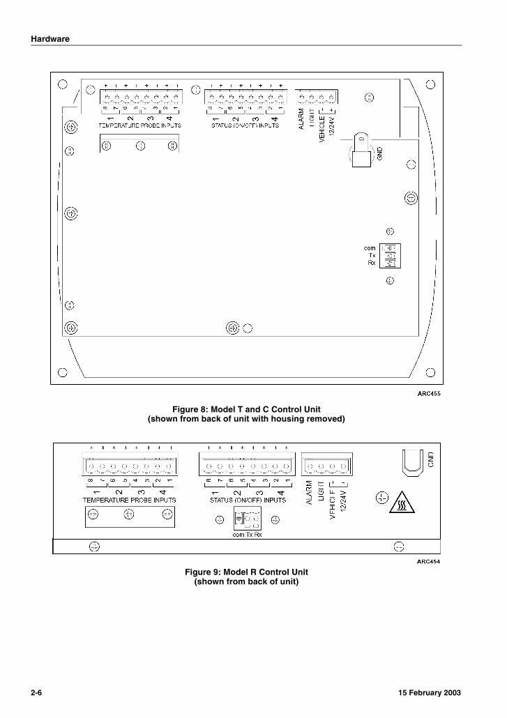
(temperature and event inputs) . . . . . . . . . . . . . . . . . . . . . . . . . . . . . . . . . . . . . . . . . . . . . . . . . . . . . 2-5Figure 8: Model T and C Control Unit
(shown from back of unit with housing removed) . . . . . . . . . . . . . . . . . . . . . . . . . . . . . . . . . . . . . . . . 2-6Figure 9: Model R Control Unit
(shown from back of unit) . . . . . . . . . . . . . . . . . . . . . . . . . . . . . . . . . . . . . . . . . . . . . . . . . . . . . . . . . . 2-6Figure 10: Temperature Out-of-Range Alarm Setup . . . . . . . . . . . . . . . . . . . . . . . . . . . . . . . . . . . . . . . 3-2Figure 11: Configuration Mode Keys . . . . . . . . . . . . . . . . . . . . . . . . . . . . . . . . . . . . . . . . . . . . . . . . . . . 3-5Figure 12: Download Jack (model T and C) . . . . . . . . . . . . . . . . . . . . . . . . . . . . . . . . . . . . . . . . . . . . . 3-6Figure 13: Download Jack (model R) . . . . . . . . . . . . . . . . . . . . . . . . . . . . . . . . . . . . . . . . . . . . . . . . . . 3-6Figure 14: Thermo King WinTrac 4 Menu . . . . . . . . . . . . . . . . . . . . . . . . . . . . . . . . . . . . . . . . . . . . . . . 3-6Figure 15: Communicating Screen . . . . . . . . . . . . . . . . . . . . . . . . . . . . . . . . . . . . . . . . . . . . . . . . . . . . 3-6Figure 16: TranScan Settings Menu General Info Tab . . . . . . . . . . . . . . . . . . . . . . . . . . . . . . . . . . . . . 3-7Figure 17: TranScan Settings Menu Advanced Tab . . . . . . . . . . . . . . . . . . . . . . . . . . . . . . . . . . . . . . . 3-7Figure 18: Exit WinTrac . . . . . . . . . . . . . . . . . . . . . . . . . . . . . . . . . . . . . . . . . . . . . . . . . . . . . . . . . . . . . 3-8Figure 19: Digital Display Panel
(all models - shown in Summary Display Mode) . . . . . . . . . . . . . . . . . . . . . . . . . . . . . . . . . . . . . . . . 4-1Figure 20: Digital Display Panel
(all models - shown in Single Display Mode) . . . . . . . . . . . . . . . . . . . . . . . . . . . . . . . . . . . . . . . . . . . 4-1Figure 21: Display Panel Indicators . . . . . . . . . . . . . . . . . . . . . . . . . . . . . . . . . . . . . . . . . . . . . . . . . . . . 4-2Figure 22: Control Panel (model T and C). . . . . . . . . . . . . . . . . . . . . . . . . . . . . . . . . . . . . . . . . . . . . . . 4-2Figure 23: Control Panel (model R) . . . . . . . . . . . . . . . . . . . . . . . . . . . . . . . . . . . . . . . . . . . . . . . . . . . . 4-2Figure 24: Help and More Help Tickets . . . . . . . . . . . . . . . . . . . . . . . . . . . . . . . . . . . . . . . . . . . . . . . . . 4-4Figure 25: Typical Delivery Ticket . . . . . . . . . . . . . . . . . . . . . . . . . . . . . . . . . . . . . . . . . . . . . . . . . . . . . 4-5Figure 26: Typical Journey Ticket (current day) . . . . . . . . . . . . . . . . . . . . . . . . . . . . . . . . . . . . . . . . . . 4-5Figure 27: Temperature Out-of-Range Alarm Troubleshooting . . . . . . . . . . . . . . . . . . . . . . . . . . . . . . . 5-2


Section 1Safety PrecautionsSafety Definitions . . . . . . . . . . . . . . . . . . . . .1-1
General Safety Practices. . . . . . . . . . . . . . . .1-1
Electrical. . . . . . . . . . . . . . . . . . . . . . . . . . . . .1-1Low Voltage. . . . . . . . . . . . . . . . . . . . . . . . .1-1Battery Removal . . . . . . . . . . . . . . . . . . . . .1-1Electrostatic Discharge Precautions . . . . . .1-1Welding Precautions . . . . . . . . . . . . . . . . . .1-2

Safety Precautions
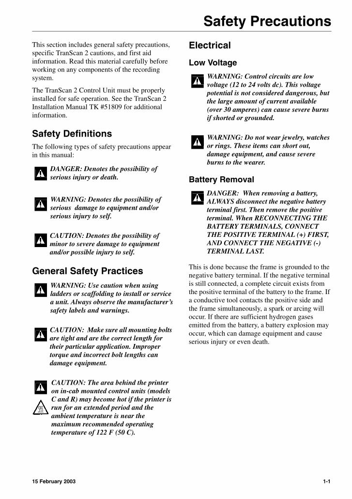
This section includes general safety precautions, specific TranScan 2 cautions, and first aid information. Read this material carefully before working on any components of the recording system.The TranScan 2 Control Unit must be properly installed for safe operation. See the TranScan 2 Installation Manual TK #51809 for additional information.
Safety DefinitionsThe following types of safety precautions appear in this manual:
General Safety Practices
Electrical
Low Voltage
Battery Removal
This is done because the frame is grounded to the negative battery terminal. If the negative terminal is still connected, a complete circuit exists from the positive terminal of the battery to the frame. If a conductive tool contacts the positive side and the frame simultaneously, a spark or arcing will occur. If there are sufficient hydrogen gases emitted from the battery, a battery explosion may occur, which can damage equipment and cause serious injury or even death.
DANGER: Denotes the possibility of serious injury or death.
WARNING: Denotes the possibility of serious damage to equipment and/or serious injury to self.
CAUTION: Denotes the possibility of minor to severe damage to equipment and/or possible injury to self.
WARNING: Use caution when using ladders or scaffolding to install or service a unit. Always observe the manufacturer’s safety labels and warnings.
CAUTION: Make sure all mounting bolts are tight and are the correct length for their particular application. Improper torque and incorrect bolt lengths can damage equipment.
CAUTION: The area behind the printer on in-cab mounted control units (models C and R) may become hot if the printer is run for an extended period and the ambient temperature is near the maximum recommended operating temperature of 122 F (50 C).
WARNING: Control circuits are low voltage (12 to 24 volts dc). This voltage potential is not considered dangerous, but the large amount of current available (over 30 amperes) can cause severe burns if shorted or grounded.
WARNING: Do not wear jewelry, watches or rings. These items can short out, damage equipment, and cause severe burns to the wearer.
DANGER: When removing a battery, ALWAYS disconnect the negative battery terminal first. Then remove the positive terminal. When RECONNECTING THE BATTERY TERMINALS, CONNECT THE POSITIVE TERMINAL (+) FIRST, AND CONNECT THE NEGATIVE (-) TERMINAL LAST.
15 February 2003 1-1
Safety Precautions
Electrostatic Discharge PrecautionsAs with other similar electronic devices, the Tran Scan 2 control unit is vulnerable to damage from Electrostatic Discharge (ESD). This damage is not always immediately apparent. As a result of ESD, a circuit can be damaged but may continue to operate temporarily only to fail later.
A grounded wrist strap should always be used when handling a control unit circuit board or PROM Chip that is not grounded to the refrigeration unit. The control unit circuit board and PROM Chip should always be stored and shipped in an anti-static bag and protective packaging.
For additional information on electrostatic discharge, refer to the Electrostatic Discharge Training Guide (TK 40282) and Service Procedure A12A in Section 6 of this manual.
Welding PrecautionsPrecautions must be taken before electric welding is performed on any portion of the unit or the vehicle to which an air conditioning unit is attached. It is necessary to ensure that welding currents are not allowed to flow through the electronic circuits of the unit. For more information, see Service Procedure A26A in Section 6 of this manual.
1-2 15 February 2003

Section 2HardwareSystem Description . . . . . . . . . . . . . . . . . . . .2-1
System Features . . . . . . . . . . . . . . . . . . . . . .2-1
System Application . . . . . . . . . . . . . . . . . . . .2-1
Control Unit . . . . . . . . . . . . . . . . . . . . . . . . . .2-2Memory (file storage) . . . . . . . . . . . . . . . . .2-2Display Panel . . . . . . . . . . . . . . . . . . . . . . .2-2Operator Keys . . . . . . . . . . . . . . . . . . . . . . .2-3Printer . . . . . . . . . . . . . . . . . . . . . . . . . . . . .2-3
Cleaning and Maintenance . . . . . . . . . . . . . .2-3
Optional Hardware. . . . . . . . . . . . . . . . . . . . .2-3Refrigeration Switch . . . . . . . . . . . . . . . . . .2-3Door Switch. . . . . . . . . . . . . . . . . . . . . . . . .2-4Defrost Switch . . . . . . . . . . . . . . . . . . . . . . .2-4Spare Switch. . . . . . . . . . . . . . . . . . . . . . . .2-4
Wiring Connections. . . . . . . . . . . . . . . . . . . .2-5
Specifications . . . . . . . . . . . . . . . . . . . . . . . .2-7Control Unit Environment . . . . . . . . . . . . . .2-7Data Collection . . . . . . . . . . . . . . . . . . . . . .2-7Electrical . . . . . . . . . . . . . . . . . . . . . . . . . . .2-8


Hardware
System DescriptionThe TranScan 2 ADR (Automatic Daily Recording System) records temperature and system events. Once installed, the system records information automatically. Records are stored in the form of daily files or “Journey Files” (a new Journey File is normally created at the beginning of each day of operation). Journey Files can be printed directly from the TranScan 2 printer or downloaded to a compatible remote computer.
NOTE: In some locations, Journey files must be retained for at least one year. The maximum interval for printing or downloading Journey Files is determined by the system configuration and the amount of recorder memory available. It is recommended to print or download Journey files monthly. Always store printed journey files in a clean and dry location to ensure they will be readable after one year.
Current temperature conditions can also be printed from the self-contained printer at any time in the form of a “Delivery Ticket”.
The TranScan 2 is a self-contained recorder and printer system that operates independently of the refrigeration system controller.
The TranScan 2 is designed to meet the recommendations of Food Hygiene Regulations with regard to the transport and delivery of refrigerated (chilled) and frozen food items in refrigerated vehicles. The TranScan 2 meets EN 12830 requirements and the objectives of the Quick Frozen Food Directive 92/1/EEC (amended by 94/43/EEC).
System FeaturesEach TranScan 2:
• Records readings from up to four separate temperature sensors at intervals from 1 minute to one hour.
• Records three system events
• Cargo area door openings
• Defrost cycles
• One user defined system event
• Includes a visible and audible alarm to warn of out-of-range temperature conditions
• Stores “Journey Files” for print or download to a compatible remote computer running WinTracTM Software
• Prints “Journey Files” and “Delivery Tickets” from a self contained printer
• R:COMTM compatible (Thermo King wireless data retrieval system)
• Requires a 10-36 Vdc power supply
System ApplicationWhen properly installed, the TranScan 2 is suitable for recording storage and transport temperatures and is compatible with all Thermo King Truck and Trailer refrigeration systems.
See the TranScan 2 Installation Manual TK #51809 for additional information.
15 February 2003 2-1
Hardware
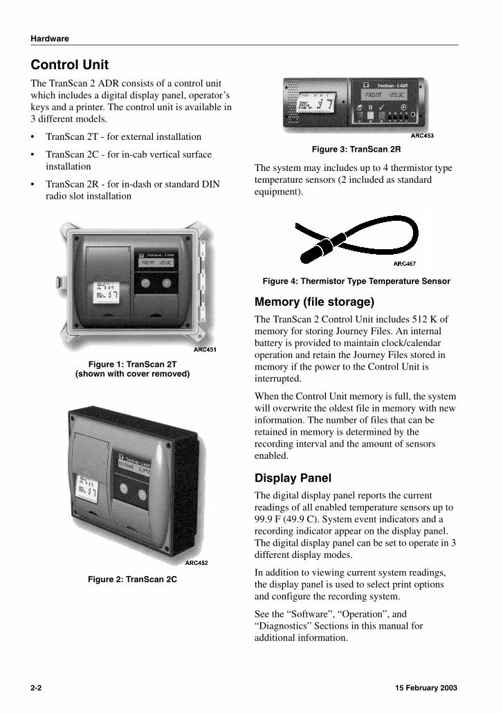
Control UnitThe TranScan 2 ADR consists of a control unit which includes a digital display panel, operator’s keys and a printer. The control unit is available in 3 different models.
• TranScan 2T - for external installation
• TranScan 2C - for in-cab vertical surface installation
• TranScan 2R - for in-dash or standard DIN radio slot installation
Figure 1: TranScan 2T(shown with cover removed)
Figure 2: TranScan 2C
Figure 3: TranScan 2R
The system may includes up to 4 thermistor type temperature sensors (2 included as standard equipment).
Figure 4: Thermistor Type Temperature Sensor
Memory (file storage)The TranScan 2 Control Unit includes 512 K of memory for storing Journey Files. An internal battery is provided to maintain clock/calendar operation and retain the Journey Files stored in memory if the power to the Control Unit is interrupted.
When the Control Unit memory is full, the system will overwrite the oldest file in memory with new information. The number of files that can be retained in memory is determined by the recording interval and the amount of sensors enabled.
Display PanelThe digital display panel reports the current readings of all enabled temperature sensors up to 99.9 F (49.9 C). System event indicators and a recording indicator appear on the display panel. The digital display panel can be set to operate in 3 different display modes.
In addition to viewing current system readings, the display panel is used to select print options and configure the recording system.
See the “Software”, “Operation”, and “Diagnostics” Sections in this manual for additional information.
2-2 15 February 2003
Hardware
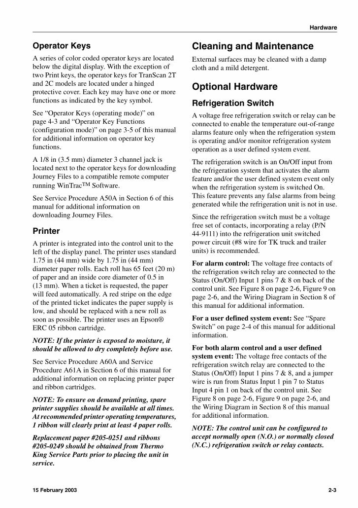
Operator KeysA series of color coded operator keys are located below the digital display. With the exception of two Print keys, the operator keys for TranScan 2T and 2C models are located under a hinged protective cover. Each key may have one or more functions as indicated by the key symbol.
See “Operator Keys (operating mode)” on page 4-3 and “Operator Key Functions (configuration mode)” on page 3-5 of this manual for additional information on operator key functions.
A 1/8 in (3.5 mm) diameter 3 channel jack is located next to the operator keys for downloading Journey Files to a compatible remote computer running WinTracTM Software.
See Service Procedure A50A in Section 6 of this manual for additional information on downloading Journey Files.
PrinterA printer is integrated into the control unit to the left of the display panel. The printer uses standard 1.75 in (44 mm) wide by 1.75 in (44 mm) diameter paper rolls. Each roll has 65 feet (20 m) of paper and an inside core diameter of 0.5 in (13 mm). When a ticket is requested, the paper will feed automatically. A red stripe on the edge of the printed ticket indicates the paper supply is low, and should be replaced with a new roll as soon as possible. The printer uses an Epson® ERC 05 ribbon cartridge.
NOTE: If the printer is exposed to moisture, it should be allowed to dry completely before use.
See Service Procedure A60A and Service Procedure A61A in Section 6 of this manual for additional information on replacing printer paper and ribbon cartridges.
NOTE: To ensure on demand printing, spare printer supplies should be available at all times. At recommended printer operating temperatures, 1 ribbon will clearly print at least 4 paper rolls.
Replacement paper #205-0251 and ribbons #205-0249 should be obtained from Thermo King Service Parts prior to placing the unit in service.
Cleaning and MaintenanceExternal surfaces may be cleaned with a damp cloth and a mild detergent.
Optional Hardware
Refrigeration SwitchA voltage free refrigeration switch or relay can be connected to enable the temperature out-of-range alarms feature only when the refrigeration system is operating and/or monitor refrigeration system operation as a user defined system event.
The refrigeration switch is an On/Off input from the refrigeration system that activates the alarm feature and/or the user defined system event only when the refrigeration system is switched On. This feature prevents any false alarms from being generated while the refrigeration unit is not in use.
Since the refrigeration switch must be a voltage free set of contacts, incorporating a relay (P/N 44-9111) into the refrigeration unit switched power circuit (#8 wire for TK truck and trailer units) is recommended.
For alarm control: The voltage free contacts of the refrigeration switch relay are connected to the Status (On/Off) Input 1 pins 7 & 8 on back of the control unit. See Figure 8 on page 2-6, Figure 9 on page 2-6, and the Wiring Diagram in Section 8 of this manual for additional information.
For a user defined system event: See “Spare Switch” on page 2-4 of this manual for additional information.
For both alarm control and a user defined system event: The voltage free contacts of the refrigeration switch relay are connected to the Status (On/Off) Input 1 pins 7 & 8, and a jumper wire is run from Status Input 1 pin 7 to Status Input 4 pin 1 on back of the control unit. See Figure 8 on page 2-6, Figure 9 on page 2-6, and the Wiring Diagram in Section 8 of this manual for additional information.
NOTE: The control unit can be configured to accept normally open (N.O.) or normally closed (N.C.) refrigeration switch or relay contacts.
15 February 2003 2-3

Hardware
Door SwitchThe TranScan 2 ADR system can be configured to display, record, and print the cargo area door status (open or closed). To monitor cargo area door activity, a voltage free door switch must be connected to the control unit.
Since the door switch must be a voltage free set of contacts, installing a separate magnetic door switch (P/N 40-0814) is recommended. The voltage free contacts of the door switch are connected to the Status (On/Off) Input 2 pins 5 & 6 on back of the control unit. See Figure 8 on page 2-6, Figure 9 on page 2-6, and the Wiring Diagram in Section 8 of this manual for additional information.
NOTE: The control unit can be configured to accept normally open (N.O.) or normally closed (N.C.) door switch contacts.
Defrost SwitchThe TranScan 2 ADR system can be configured to display, record, and print refrigeration system defrost cycles (On or Off). To monitor defrost cycles, a voltage free defrost switch or relay must be connected to the control unit.
The defrost switch is an On/Off input that changes when the refrigeration system is operating in Defrost Mode. This feature helps explain a change in temperature sensor readings caused by a refrigeration unit defrost cycle. The defrost switch must be a voltage free set of contacts.
On refrigeration units with a motor driven defrost damper, a separate magnetic switch (P/N 40-0814) can be installed on the defrost damper door. To simplify installation, the switch can be installed in either the defrost damper door open or closed position.
On refrigeration units with a solenoid driven defrost damper, a relay (P/N 44-9111) can be incorporated into the defrost damper solenoid circuit.
The voltage free defrost switch or relay contacts are connected to the Status (On/Off) Input 3 pins 3 & 4 on back of the control unit. See Figure 8 on page 2-6, Figure 9 on page 2-6, and the Wiring Diagram in Section 8 of this manual for additional information.
NOTE: The control unit can be configured to accept normally open (N.O.) or normally closed (N.C.) defrost switch or relay contacts.
Spare SwitchThe TranScan 2 ADR system can be configured to display, record, and print an additional user defined system event (On or Off, open or closed). This feature allows monitoring the activity of a second cargo area door, or an additional refrigeration system operating mode.
The spare switch must be a voltage free set of contacts. A separate magnetic door switch (P/N 40-0814) can be installed to monitor a second cargo area door, or a relay (P/N 44-9111) can be incorporated into the refrigeration unit circuitry to monitor a refrigeration system event.
The voltage free contacts of the spare switch or relay are connected to the Status (On/Off) Input 4 pins 1 & 2 on back of the control unit. See Figure 8 on page 2-6, Figure 9 on page 2-6, and the Wiring Diagram in Section 8 of this manual for additional information.
NOTE: The control unit can be configured to accept normally open (N.O.) or normally closed (N.C.) spare switch or relay contacts.
2-4 15 February 2003

Hardware
Wiring ConnectorsThe following connectors are used with the TranScan 2 control unit. The connection labels shown here are for your convenience, and do not appear on the actual connectors. See the Wiring Diagram in Section 8 of this manual for additional information.
Figure 5: 3 Pin Connector(serial port for optional R-Com radio transmitter)
Figure 6: 4 Pin Connector(power inputs and lighting outputs)
Figure 7: 8 Pin Connector(temperature and event inputs)
15 February 2003 2-5
Hardware
Figure 8: Model T and C Control Unit(shown from back of unit with housing removed)
Figure 9: Model R Control Unit(shown from back of unit)
2-6 15 February 2003

Hardware
Specifications
Control Unit Environment
Data Collection
Recorder
Operating Temperature (recording) -22 F to 158 F (-30 C to 70 C)
Transport and Storage (unpowered) 14 F to 185 F (-10 C to 85 C)
Moisture Protection(recorder unit only - not printer)
IP65 (external mount model 2T)
IP22 (internal mount model 2R and 2C)
Printer
Operating Temperature (printing) -14 F to 122 F (-10 C to 50 C)
Paper 1.75 in (44 mm) wide by 1.75 in (44 mm) diameter65 feet (20 m) of paper per rollinside core diameter 0.5 in (13 mm)
Ribbon (ink) Epson ERC 05 ribbon cartridge
Temperature Measurement
Certified Range -22 F to 86 F (-30 C to 30 C)
For Germany -31 F to 77 F (-35 C to 25 C)
Available Range -58 F to 122 F (-50 C to 50 C)Note: Temperatures over 99.9 F appear as [++] on the control unit display panel. Temperatures below -57.9 F appear as [--] on the control unit display panel.
Accuracy Class 1 (1.0 C at a resolution of 0.5 C)
EMC Conforms with EN50081-1 and EN50082-1 with a radiated immunity of 10v/m when properly installed
Time Measurement
Recording Interval User defined from 1 to 60 minute intervals.
Program includes 1, 2, 5, 10, 15, 20, 30, and 60 minute presets
Note: To comply to current German legislation, the recording interval must not exceed 15 minutes.
Recording Duration (15 minute recording interval) 512 K memory 988 days (1 or 2 sensors)640 days (3 or 4 sensors)
Accuracy Relative error - less than 0.1% (less than 15 minute in 7 days)
Typical error - less than 0.01% (less than 1 minute in 7 days)
15 February 2003 2-7
Hardware
Electrical
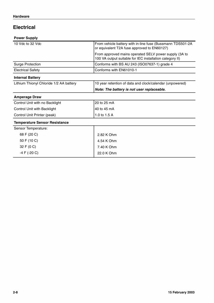
Power Supply
10 Vdc to 32 Vdc From vehicle battery with in-line fuse (Bussmann TDS501-2A or equivalent T2A fuse approved to EN60127)
From approved mains operated SELV power supply (3A to 100 VA output suitable for IEC installation category II)
Surge Protection Conforms with BS AU 243 (ISO07637-1) grade 4
Electrical Safety Conforms with EN61010-1
Internal Battery
Lithium Thionyl Chloride 1/2 AA battery 10 year retention of data and clock/calendar (unpowered)
Note: The battery is not user replaceable.
Amperage Draw
Control Unit with no Backlight
Control Unit with Backlight
Control Unit Printer (peak)
20 to 25 mA
40 to 45 mA
1.0 to 1.5 A
Temperature Sensor Resistance
Sensor Temperature:
68 F (20 C)
50 F (10 C)
32 F (0 C)
-4 F (-20 C)
2.82 K Ohm
4.54 K Ohm
7.40 K Ohm
22.0 K Ohm
2-8 15 February 2003
Section 3SoftwareDescription . . . . . . . . . . . . . . . . . . . . . . . . . . .3-1
Revisions . . . . . . . . . . . . . . . . . . . . . . . . . . . .3-1
Programmable Features . . . . . . . . . . . . . . . .3-1Programming (configuration) Aids. . . . . . . .3-1Temperature Out-of-Range Alarms . . . . . . .3-1User Options Mode . . . . . . . . . . . . . . . . . . .3-3
Setting the Display Language . . . . . . . .3-3Setting the Print Orientation . . . . . . . . . .3-3Setting the Control Unit Model . . . . . . . .3-3Setting the Display Unit of Measure . . . .3-3
Configuration Mode. . . . . . . . . . . . . . . . . . .3-4Enter Configuration Mode using the
Operator Keys . . . . . . . . . . . . . . . . . .3-4Operator Key Functions
(configuration mode) . . . . . . . . . . . . .3-5Enter Configuration Mode
using a Remote Computer. . . . . . . . .3-6Configuration Menu. . . . . . . . . . . . . . . . . . .3-8
[Start time hh:mm]Set Recording Start Time . . . . . . . . .3-8
[Stop time hh:mm]Set Recording Stop Time. . . . . . . . . .3-8
[Log by Day XXX]Select Weekly Recording Schedule. .3-8
[Day Code XXXXXXX]Set Days for Weekly Recording Schedule . . . . . . . . . . . . . . . . . . . . . .3-9
[min/update 00XX]Set Recording Interval . . . . . . . . . . . .3-9
[mms/hour 00XX]Set Graph Print Density . . . . . . . . . . .3-9
[Door switch XXX]Enable System Event - Door . . . . . . .3-9
[Door reverse XXX]Reverse Door Switch Signal . . . . . .3-10
[DeIce switch XXX]Enable System Event - DeIce(Defrost). . . . . . . . . . . . . . . . . . . . . .3-10
[DIce reverse XXX]Reverse DeIce (Defrost) SwitchSignal. . . . . . . . . . . . . . . . . . . . . . . .3-10
[Spare switch XXX]Enable System Event - Spare . . . . .3-10
[Spr reverse XXX]Reverse Spare Switch Signal . . . . . 3-11
[Spr name XXXXXXX]Spare Switch Name. . . . . . . . . . . . . 3-11
[Spare symbol X]Spare Switch Event IndicatorSymbol . . . . . . . . . . . . . . . . . . . . . . 3-11
[Alarm enable XXX]Enable Temperature Out-of-Range Alarm. . . . . . . . . . . . . . . . . . . . . . . . 3-11
[Alarm reverse XXX]Reverse Refrigeration SwitchSignal . . . . . . . . . . . . . . . . . . . . . . . 3-11
[Extend time XXX]Enable Extended AlarmMonitoring . . . . . . . . . . . . . . . . . . . . 3-12
[Added time hh:mm]Set Extended Alarm MonitoringPeriod . . . . . . . . . . . . . . . . . . . . . . . 3-12
[Graph high X00XX]Graph Print High Limit(alarm sets disabled). . . . . . . . . . . . 3-12
[Graph low X00XX]Graph Print Low Limit(alarm sets disabled). . . . . . . . . . . . 3-12
[Preset names XXX]Preset Sensor and Alarm SetNames. . . . . . . . . . . . . . . . . . . . . . . 3-12
[Temperature# XXX]Enable Temperature Sensor T# . . . 3-13
[T# name XXXXXXX]Temperature Sensor T# Name . . . . 3-13
[Alarm set # XXX]Enable Alarm Set # . . . . . . . . . . . . . 3-13
[A# name XXXXXXX]Alarm Set # Name. . . . . . . . . . . . . . 3-13
[High alarm X00XX]High Temperature Alarm Limit . . . . 3-14
[Low alarm X00XX]Low Temperature Alarm Limit . . . . . 3-14
[Alarm wait 0XXX]Alarm Delay Period . . . . . . . . . . . . . 3-14
[Graph high X00XX]Graph Print High Limit(alarm set enabled) . . . . . . . . . . . . . 3-14
[Graph low X00XX]Graph Print Low Limit(alarm set enabled) . . . . . . . . . . . . . 3-14
[Print T# XXX]Print Sensor T# Data . . . . . . . . . . . 3-15
[Alarm on T# XXX]Enable Sensor T# Alarms . . . . . . . . 3-15

[T# AlarmSet1 XXX]Alarm Set 1 Available to SensorT# . . . . . . . . . . . . . . . . . . . . . . . . . .3-15
[T# AlarmSet2 XXX]Alarm Set 2 Available to SensorT# . . . . . . . . . . . . . . . . . . . . . . . . . .3-15
[T# AutoAlarm XXX]Auto Alarm Set Available to SensorT# . . . . . . . . . . . . . . . . . . . . . . . . . .3-16
[T# No Alarms XXX]Disable Alarm Monitoring Available to Sensor T# . . . . . . . . . . . . . . . . . . . .3-16
[Print Door XXX]Print Door Switch Data . . . . . . . . . .3-16
[Print De-Ice XXX]Print DeIce (Defrost) Switch Data . .3-16
[Print Spare XXX]Print Spare Switch Data . . . . . . . . .3-16
[ENG Display XXX]View Additional Screens andSettings . . . . . . . . . . . . . . . . . . . . . .3-17
[R standard XXXX]Standard Calibration Constant . . . .3-17
[T# cal val XXXX]Sensor T# Standard Calibration . . .3-17
[PIN number XXXX]Set Security Code . . . . . . . . . . . . . .3-17
[Unit I/D XXXXXX]Control Unit Identification Number. .3-18
[Baud rate XXXX]Serial Port Communication Speed .3-18
[Date DD Mon’ YY]Set System Calendar. . . . . . . . . . . .3-18
[Set clock hh:mm]Set System Clock . . . . . . . . . . . . . .3-19
[Auto Clk Adj XXX]Automatic Clock Adjustment . . . . . .3-19
[Clk Protect XXX]Clock Adjustment Protection . . . . . .3-19
[Vehicle XXXXXXXX]Vehicle Identification Number . . . . .3-20
[Title1 XXXXXXXX]Ticket Heading (1st 8 of 16 digits) . .3-20
[Title2 XXXXXXXX]Ticket Heading (2nd 8 of 16 digits) .3-20
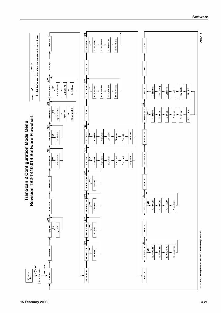
Configuration Menu Flowchart . . . . . . . . .3-20TranScan 2 Configuration Mode Menu
Revision TS2-T410.014 Software Flowchart . . . . . . . . . . . . . . . . . . . . .3-21

Software
DescriptionThe software is a complex set of instructions used to operate the TranScan 2 ADR control unit. The control unit examines the conditions of all the inputs, compares them to the instructions contained in the software, and reacts accordingly.
The software can be changed by replacing the PROM Chip in the control unit. See Service Procedure A13A in Section 6 of this manual for additional information.
RevisionsThere are several revisions of software used with the TranScan 2 ADR system. In addition, upgrade software may be made available that incorporates new features. It is very important that the correct revision of software be installed in the control unit.
To check the current software revision, see Service Procedure A06A in Section 6 of this manual.
Always consult Service Information A16A “Software (PROM Chip) interchange and Service Part Numbers” in Section 7 of this manual when replacing software or control units.
Programmable FeaturesThe TranScan 2 ADR includes many programmable features. These features are designed to allow end users to configure each control unit to local, regional, or their own special requirements.
NOTE: The unit is factory set to record continuously 24 hours a day 7 days a week.
Programming (configuration) AidsWhen programming a new control unit, it is wise to obtain and complete a copy of the Setup Information Sheet found at the end of Service Procedure A02A in Section 6 of this manual. Be certain all customer specified settings are included when completing the setup sheet. Use the completed setup sheet to confirm that each setting is programed as desired.
When working with an existing control unit, obtain a Parameter Ticket. See Service Procedure A02A in Section 6 of this manual for additional information.
If a quick comparison of the configuration settings for a number of control units with the same software revision is necessary, a Configuration Signature feature is available. See Service Procedure A70A in Section 6 of this manual for additional information.
Temperature Out-of-Range AlarmsThis feature records, displays, and sounds an alarm if a temperature sensor reading raises above or drops below the desired temperature range.
Keep the following steps in mind when setting up the temperature out-of-range alarms feature:
1. Program when to automatically start and stop monitoring the system for alarms. The system can be configured to start and stop monitoring for alarms manually, or automatically by incorporating a refrigeration switch. These settings are different then the recording start and stop times.
See “Enable Temperature Out-of-Range Alarm” and “Enable Extended Alarm Monitoring” beginning on page 3-11 for additional information.
2. Program the conditions for one or both of the available alarm sets.
See “Enable Alarm Set #” beginning on page 3-13 for additional information.
3. Program which sensors should be monitored for alarms. Any, all, or none of the available sensors can be monitored.
See “Enable Sensor T# Alarms” beginning on page 3-15 for additional information.
15 February 2003 3-1
Software
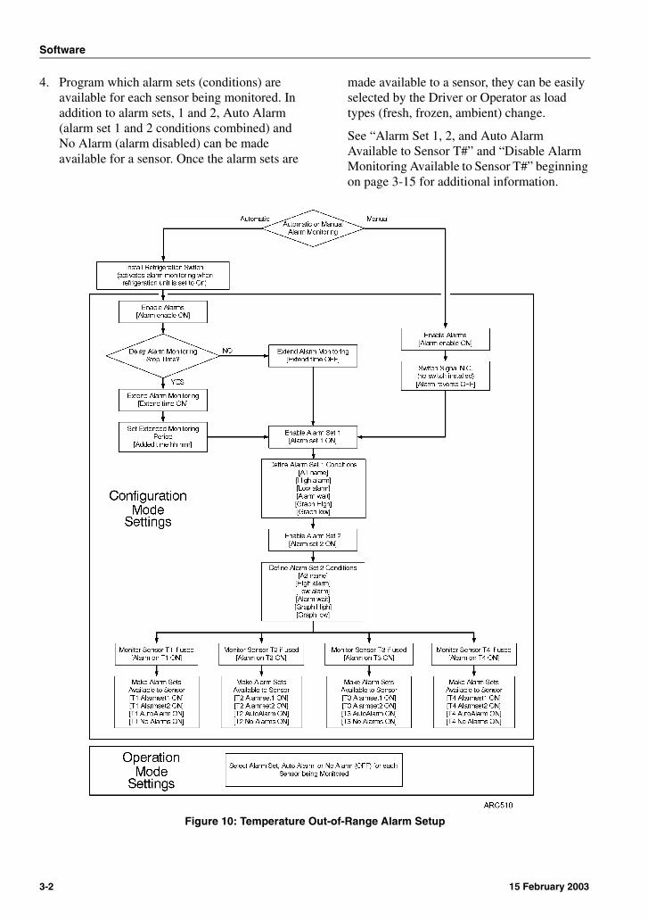
4. Program which alarm sets (conditions) are available for each sensor being monitored. In addition to alarm sets, 1 and 2, Auto Alarm (alarm set 1 and 2 conditions combined) and No Alarm (alarm disabled) can be made available for a sensor. Once the alarm sets are
made available to a sensor, they can be easily selected by the Driver or Operator as load types (fresh, frozen, ambient) change.
See “Alarm Set 1, 2, and Auto Alarm Available to Sensor T#” and “Disable Alarm Monitoring Available to Sensor T#” beginning on page 3-15 for additional information.
Figure 10: Temperature Out-of-Range Alarm Setup
3-2 15 February 2003
Software
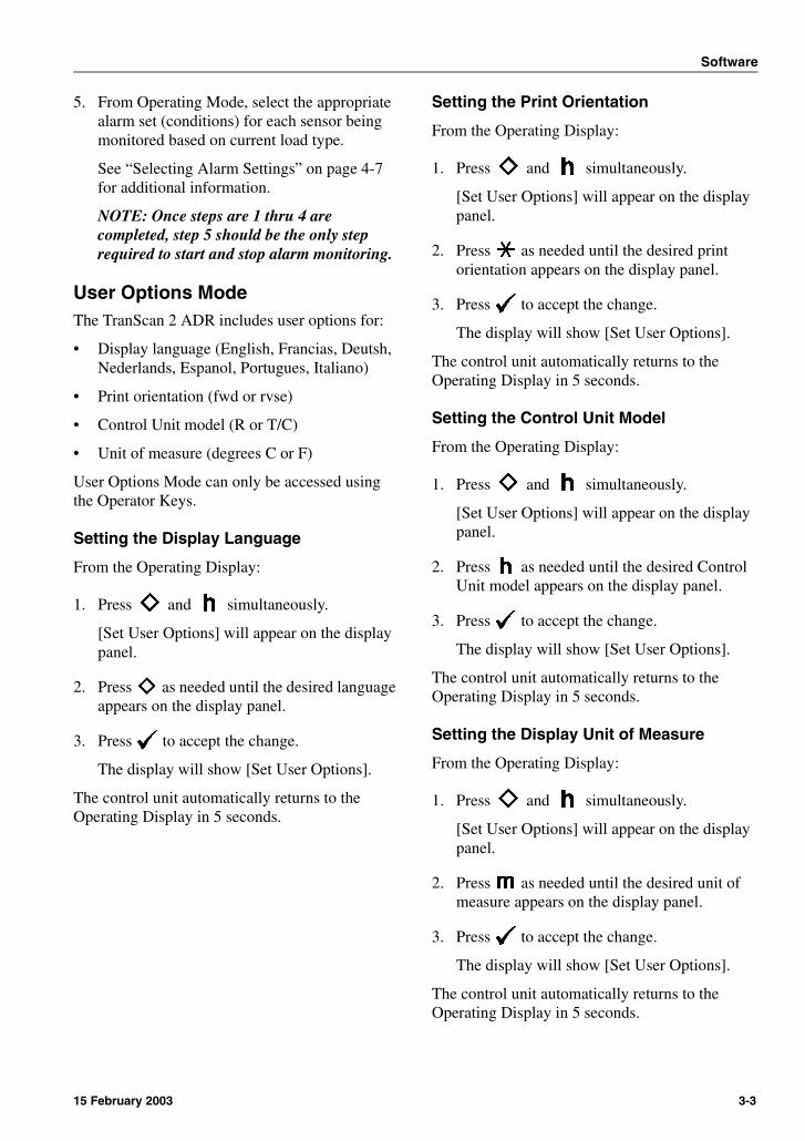
5. From Operating Mode, select the appropriate alarm set (conditions) for each sensor being monitored based on current load type.
See “Selecting Alarm Settings” on page 4-7 for additional information.
NOTE: Once steps are 1 thru 4 are completed, step 5 should be the only step required to start and stop alarm monitoring.
User Options ModeThe TranScan 2 ADR includes user options for:
• Display language (English, Francias, Deutsh, Nederlands, Espanol, Portugues, Italiano)
• Print orientation (fwd or rvse)
• Control Unit model (R or T/C)
• Unit of measure (degrees C or F)
User Options Mode can only be accessed using the Operator Keys.
Setting the Display Language
From the Operating Display:
1. Press and simultaneously.
[Set User Options] will appear on the display panel.
2. Press as needed until the desired language appears on the display panel.
3. Press to accept the change.
The display will show [Set User Options].
The control unit automatically returns to the Operating Display in 5 seconds.
Setting the Print Orientation
From the Operating Display:
1. Press and simultaneously.
[Set User Options] will appear on the display panel.
2. Press as needed until the desired print orientation appears on the display panel.
3. Press to accept the change.
The display will show [Set User Options].
The control unit automatically returns to the Operating Display in 5 seconds.
Setting the Control Unit Model
From the Operating Display:
1. Press and simultaneously.
[Set User Options] will appear on the display panel.
2. Press as needed until the desired Control Unit model appears on the display panel.
3. Press to accept the change.
The display will show [Set User Options].
The control unit automatically returns to the Operating Display in 5 seconds.
Setting the Display Unit of Measure
From the Operating Display:
1. Press and simultaneously.
[Set User Options] will appear on the display panel.
2. Press as needed until the desired unit of measure appears on the display panel.
3. Press to accept the change.
The display will show [Set User Options].
The control unit automatically returns to the Operating Display in 5 seconds.
15 February 2003 3-3
Software
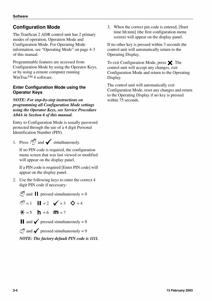
Configuration ModeThe TranScan 2 ADR control unit has 2 primary modes of operation, Operation Mode and Configuration Mode. For Operating Mode information, see “Operating Mode” on page 4-3 of this manual.
Programmable features are accessed from Configuration Mode by using the Operator Keys, or by using a remote computer running WinTracTM 4 software.
Enter Configuration Mode using the Operator Keys
NOTE: For step-by-step instructions on programming all Configuration Mode settings using the Operator Keys, see Service Procedure A04A in Section 6 of this manual.
Entry to Configuration Mode is usually password protected through the use of a 4 digit Personal Identification Number (PIN).
1. Press and simultaneously.
If no PIN code is required, the configuration menu screen that was last viewed or modified will appear on the display panel.
If a PIN code is required [Enter PIN code] will appear on the display panel.
2. Use the following keys to enter the correct 4 digit PIN code if necessary:
and pressed simultaneously = 0
= 1 = 2 = 3 = 4
= 5 = 6 = 7
and pressed simultaneously = 8
and pressed simultaneously = 9
NOTE: The factory default PIN code is 1111.
3. When the correct pin code is entered, [Start time hh:mm] (the first configuration menu screen) will appear on the display panel.
If no other key is pressed within 3 seconds the control unit will automatically return to the Operating Display.
To exit Configuration Mode, press . The control unit will accept any changes, exit Configuration Mode and return to the Operating Display.
The control unit will automatically exit Configuration Mode, reset any changes and return to the Operating Display if no key is pressed within 75 seconds.
3-4 15 February 2003

Software
Operator Key Functions(configuration mode)
The keys have different functions based on the control unit mode. The following descriptions explain the key functions while in Configuration Mode. The symbol for each configuration mode key function is located below the key.
Model T and C
Model R
Previous Menu Screen
Use this key to display the previous available configuration menu screen and its current setting.
Next Menu Screen
Use this key to display the next available configuration menu screen and its current setting.
Move Cursor Position to Left or Toggle Between On and Off Values
On menu screens that require a numeric or alphabetic entry, use this key to move the cursor (horizontal bar at the bottom of the display indicating current entry location) to the left.
On menu screens that require an On or Off entry, use this key to toggle between On and Off.
Move Cursor Position Right or Toggle Between On and Off Values
On menu screens that require a numeric or alphabetic entry, use this key to move the cursor (horizontal bar at the bottom of the display indicating current entry location) to the right.
On menu screens that require an On or Off entry, use this key to toggle between On and Off.
Scroll Backward Through Available Values
On menu screens that require a numeric or alphabetic entry, use this key to scroll backward through the available selections.
Scroll Forward Through Available Values
On menu screens that require a numeric or alphabetic entry, use this key to scroll backward through the available selections.
Exit Configuration Mode
Use this key to accept changes, exit configuration mode and return to the Operating Display.
1. Previous Screen (blue)
5. Move Cursor to Right or Toggle On/Off
2. Exit Configuration Mode (yellow)
6. Scroll Selections Backward
3. Next Screen (red) 7. Scroll Selections Forward
4. Move Cursor to Left or Toggle On/Off
Figure 11: Configuration Mode Keys
1
5
2 3 4
6 7
5 6 7 1 2 3 4
15 February 2003 3-5
Software
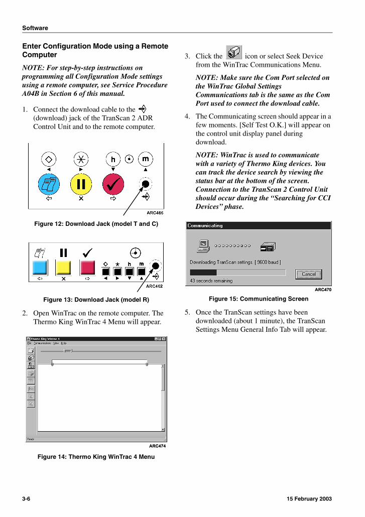
Enter Configuration Mode using a Remote Computer
NOTE: For step-by-step instructions on programming all Configuration Mode settings using a remote computer, see Service Procedure A04B in Section 6 of this manual.
1. Connect the download cable to the (download) jack of the TranScan 2 ADR Control Unit and to the remote computer.
Figure 12: Download Jack (model T and C)
Figure 13: Download Jack (model R)
2. Open WinTrac on the remote computer. The Thermo King WinTrac 4 Menu will appear.
Figure 14: Thermo King WinTrac 4 Menu
3. Click the icon or select Seek Device from the WinTrac Communications Menu.
NOTE: Make sure the Com Port selected on the WinTrac Global Settings Communications tab is the same as the Com Port used to connect the download cable.
4. The Communicating screen should appear in a few moments. [Self Test O.K.] will appear on the control unit display panel during download.
NOTE: WinTrac is used to communicate with a variety of Thermo King devices. You can track the device search by viewing the status bar at the bottom of the screen. Connection to the TranScan 2 Control Unit should occur during the “Searching for CCI Devices” phase.
Figure 15: Communicating Screen
5. Once the TranScan settings have been downloaded (about 1 minute), the TranScan Settings Menu General Info Tab will appear.
3-6 15 February 2003
Software
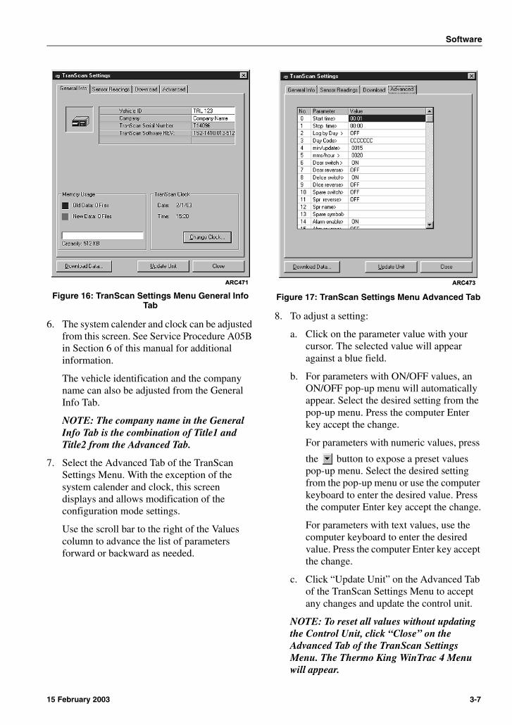
Figure 16: TranScan Settings Menu General Info Tab
6. The system calender and clock can be adjusted from this screen. See Service Procedure A05B in Section 6 of this manual for additional information.
The vehicle identification and the company name can also be adjusted from the General Info Tab.
NOTE: The company name in the General Info Tab is the combination of Title1 and Title2 from the Advanced Tab.
7. Select the Advanced Tab of the TranScan Settings Menu. With the exception of the system calender and clock, this screen displays and allows modification of the configuration mode settings.
Use the scroll bar to the right of the Values column to advance the list of parameters forward or backward as needed.
Figure 17: TranScan Settings Menu Advanced Tab
8. To adjust a setting:
a. Click on the parameter value with your cursor. The selected value will appear against a blue field.
b. For parameters with ON/OFF values, an ON/OFF pop-up menu will automatically appear. Select the desired setting from the pop-up menu. Press the computer Enter key accept the change.
For parameters with numeric values, press
the button to expose a preset values pop-up menu. Select the desired setting from the pop-up menu or use the computer keyboard to enter the desired value. Press the computer Enter key accept the change.
For parameters with text values, use the computer keyboard to enter the desired value. Press the computer Enter key accept the change.
c. Click “Update Unit” on the Advanced Tab of the TranScan Settings Menu to accept any changes and update the control unit.
NOTE: To reset all values without updating the Control Unit, click “Close” on the Advanced Tab of the TranScan Settings Menu. The Thermo King WinTrac 4 Menu will appear.
15 February 2003 3-7
Software
9. Click “Close” on the Advanced Tab of the TranScan Settings Menu to return to the Thermo King WinTrac 4 Menu.
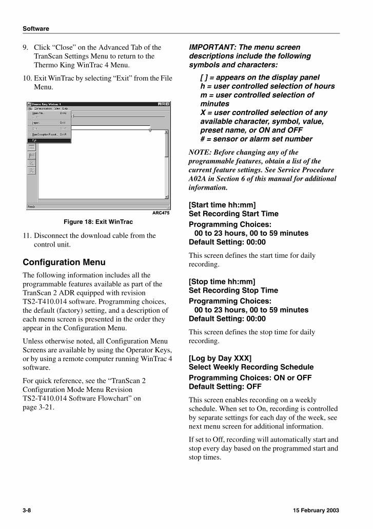
10. Exit WinTrac by selecting “Exit” from the File Menu.
Figure 18: Exit WinTrac
11. Disconnect the download cable from the control unit.
Configuration MenuThe following information includes all the programmable features available as part of the TranScan 2 ADR equipped with revision TS2-T410.014 software. Programming choices, the default (factory) setting, and a description of each menu screen is presented in the order they appear in the Configuration Menu.
Unless otherwise noted, all Configuration Menu Screens are available by using the Operator Keys, or by using a remote computer running WinTrac 4 software.
For quick reference, see the “TranScan 2 Configuration Mode Menu Revision TS2-T410.014 Software Flowchart” on page 3-21.
IMPORTANT: The menu screen descriptions include the following symbols and characters:
[ ] = appears on the display panelh = user controlled selection of hoursm = user controlled selection of minutesX = user controlled selection of any available character, symbol, value, preset name, or ON and OFF# = sensor or alarm set number
NOTE: Before changing any of the programmable features, obtain a list of the current feature settings. See Service Procedure A02A in Section 6 of this manual for additional information.
[Start time hh:mm]Set Recording Start TimeProgramming Choices:
00 to 23 hours, 00 to 59 minutesDefault Setting: 00:00
This screen defines the start time for daily recording.
[Stop time hh:mm]Set Recording Stop TimeProgramming Choices:
00 to 23 hours, 00 to 59 minutesDefault Setting: 00:00
This screen defines the stop time for daily recording.
[Log by Day XXX]Select Weekly Recording ScheduleProgramming Choices: ON or OFFDefault Setting: OFF
This screen enables recording on a weekly schedule. When set to On, recording is controlled by separate settings for each day of the week, see next menu screen for additional information.
If set to Off, recording will automatically start and stop every day based on the programmed start and stop times.
3-8 15 February 2003

Software
[Day Code XXXXXXX]Set Days for Weekly Recording ScheduleProgramming Choices: 0, 1, S, T, and C,
for each day of the week starting with Sunday
Default Setting: CCCCCCC
Each of the seven spaces on this screen controls the recording activity for each of the seven days of a weekly recording schedule beginning with Sunday. Select any one of the following recording options for each day:
0 = Do not record1 = Record for 24 hoursS = Start recording at programmed start timeT = Stop recording at programmed stop timeC = Start and stop recording at programmed start and stop times
Example 1:The setting [Day Code 0CCCCC0] will start and stop recording data at the programmed times on Monday through Friday. This setting creates a separate Journey Ticket or file for each day of the week except Saturday and Sunday.
Example 2:The setting [Day Code 0S111T0] will start recording data at the programmed start time on Monday, and continue uninterrupted recording until the programmed stop time on Friday. This setting creates a single Journey Ticket or file for the entire period Monday through Friday.
[min/update 00XX]Set Recording IntervalProgramming Choices: 1 to 60 minutes in
1 minute incrementsDefault Setting: 0010
The recording interval represents the rate at which the recordings are made. The value written to memory is the average temperature over the recording interval calculated from samples taken every few seconds.
The recording interval can also be set to 1, 2, 5, 10, 15, 30, and 60 minute preset intervals through Operating Mode. See “Adjusting Recording Interval” on page 4-7 for additional information.
NOTE: Note: To comply to current German legislation, the recording interval must not exceed 15 minutes.
[mms/hour 00XX]Set Graph Print DensityProgramming Choices: 1 to 60 millimeters
in 1 mm incrementsDefault Setting: 0020
This screen controls the density (distance between hours) for a graph on any printed ticket.
NOTE: 1 inch = 25.4 mm
[Door switch XXX]Enable System Event - DoorProgramming Choices: ON or OFFDefault Setting: OFF
One of the pre-programmed system events is monitoring a cargo area door. Set this feature to On if a voltage free door switch is used. See “Door Switch” on page 2-4 for additional information.
The voltage free contacts of the door switch are connected to Status (On/Off) Input 2 pins 5 & 6 on back of the control unit. See Figure 8 on page 2-6, Figure 9 on page 2-6, and the Wiring Diagram in Section 8 of this manual for additional information.
15 February 2003 3-9
Software
[Door reverse XXX]Reverse Door Switch SignalProgramming Choices: ON or OFFDefault Setting: OFF
This screen only appears when [Door switch XXX] is set to On.
Set this feature to Off when a normally closed (N.C.) door switch is used. The control unit will assume the door is closed when the switch contacts are closed and the circuit is complete.
Set this feature to On when a normally open (N.O.) door switch is used. The control unit will assume the door is closed when the switch contacts are open and the circuit is interrupted.
[DeIce switch XXX]Enable System Event - DeIce (Defrost)Programming Choices: ON or OFFDefault Setting: OFF
One of the pre-programmed system events is monitoring the refrigeration system defrost cycles. Set this feature to On if a voltage free defrost switch or relay is used. See “Defrost Switch” on page 2-4 for additional information.
The voltage free defrost switch or relay contacts are connected to Status (On/Off) Input 3 pins 3 & 4 on back of the control unit. See Figure 8 on page 2-6, Figure 9 on page 2-6, and the Wiring Diagram in Section 8 of this manual for additional information.
[DIce reverse XXX]Reverse DeIce (Defrost) Switch SignalProgramming Choices: ON or OFFDefault Setting: ON
This screen only appears when [DeIce switch XXX] is set to On.
Set this feature to On when a normally open (N.O.) defrost switch or relay is used. The control unit will assume the refrigeration system is operating in Defrost Mode when the switch or relay contacts are closed and the circuit is complete.
Set this feature to Off when a normally closed (N.C.) defrost switch or relay is used. The control unit will assume the refrigeration system is operating in Defrost Mode when the switch or relay contacts are open and the circuit is interrupted.
[Spare switch XXX]Enable System Event - SpareProgramming Choices: ON or OFFDefault Setting: OFF
Monitoring one user defined system event is available. Set this feature to On if an additional cargo area door switch, or another type of event relay is used. See “Spare Switch” on page 2-4 for additional information.
The voltage free contacts of the spare switch or relay are connected to Status (On/Off) Input 4 pins 1 & 2 on back of the control unit. See Figure 8 on page 2-6, Figure 9 on page 2-6, and the Wiring Diagram in Section 8 of this manual for additional information.
3-10 15 February 2003
Software
[Spr reverse XXX]Reverse Spare Switch SignalProgramming Choices: ON or OFFDefault Setting: OFF
This screen only appears when [Spare switch XXX] is set to On.
Set this feature to Off when a normally closed (N.C.) switch or relay is used. The control unit will assume the event being monitored is Off or closed when the switch or relay contacts are closed and the circuit is complete.
Set this feature to On when a normally open (N.O.) switch or relay is used. The control unit will assume the event being monitored is Off or closed when the switch or relay contacts are open and the circuit is interrupted.
[Spr name XXXXXXX]Spare Switch NameProgramming Choices: Any combination
of up to 7 available characters, numerals, symbols, and spaces
Default Setting: (user defined)
This screen only appears when [Spare switch XXX] is set to On.
This screen sets the name used to represent the user defined spare switch.
[Spare symbol X]Spare Switch Event Indicator SymbolProgramming Choices: Any 1 available
symbol, character, or numeralDefault Setting: Door Symbol
This screen only appears when [Spare switch XXX] is set to On.
This screen sets the display panel Event Indicator symbol used to represent the user defined spare system event. See “Display Panel Indicators” on page 4-2 for additional information.
NOTE: The door symbol (rectangle) is selected by using a space (blank).
[Alarm enable XXX]Enable Temperature Out-of-Range AlarmProgramming Choices: ON or OFFDefault Setting: OFF
Set this Screen to On if the temperature out-of-range alarms feature is desired, and a voltage free refrigeration switch relay is used. See “Refrigeration Switch” on page 2-3 for additional information.
The refrigeration switch is an On/Off input from the refrigeration system that activates the alarm feature only when the refrigeration system is switched On. This feature prevents any false alarms from being generated while the refrigeration unit is not in use.
The voltage free contacts of the refrigeration switch relay are connected to the Status (On/Off) Input 1 pins 7 & 8 on back of the control unit. See Figure 8 on page 2-6, Figure 9 on page 2-6, and the Wiring Diagram in Section 8 of this manual for additional information.
[Alarm reverse XXX]Reverse Refrigeration Switch SignalProgramming Choices: ON or OFFDefault Setting: ON
This screen only appears when [Alarm enable XXX] is set to On.
Set this feature to On when a normally open (N.O.) refrigeration switch relay is used. The control unit will assume the refrigeration system is operating when the refrigeration switch relay contacts are closed and the circuit is complete.
Set this feature to Off when a normally closed (N.C.) refrigeration switch is used. The control unit will assume the refrigeration system is operating when the refrigeration switch relay contacts are open and the circuit is interrupted.
NOTE: If a refrigeration switch is not installed, and this feature is set to Off, alarm monitoring may be controlled manually through Operating Mode. See “[Alarm on T# XXX] Enable Sensor T# Alarms” on page 3-15 of this manual for additional information.
15 February 2003 3-11
Software
[Extend time XXX]Enable Extended Alarm MonitoringProgramming Choices: ON or OFFDefault Setting: ON
This screen only appears when [Alarm enable XXX] is set to On.
Setting this screen to On allows the control unit to continue monitoring temperature out-of-range alarms for a programmed period of time after the refrigeration unit is turned Off. The amount of time is determined by the [Added time hh:mm] screen. This feature is ideal for applications that switch the refrigeration unit Off during deliveries.
[Added time hh:mm]Set Extended Alarm Monitoring Period00 to 23 hours, 00 to 59 minutesDefault Setting: 00:45
This screen only appears when [Extend time XXX] is set to On.
This screen sets the amount of time after the refrigeration unit is turned Off that the control unit will continue to monitor temperature out-of-range alarms.
[Graph high X00XX]Graph Print High Limit(alarm sets disabled)Programming Choices:
–0050 to 0050 degrees F or CDefault Setting: 0010
This screen controls the upper temperature limit (highest temperature) that can be printed on any graph style ticket when no alarm sets are enabled. If an alarm set is enabled, this setting is controlled by the Graph High setting for that alarm set.
[Graph low X00XX]Graph Print Low Limit(alarm sets disabled)Programming Choices:
–0050 to 0050 degrees F or CDefault Setting: –0030
This screen controls the lower temperature limit (lowest temperature) that can be printed on any graph style ticket when no alarm sets are enabled. If an alarm set is enabled, this setting is controlled by the Graph Low setting for that alarm set.
[Preset names XXX]Preset Sensor and Alarm Set NamesProgramming Choices: ON or OFFDefault Setting: ON
Setting this feature to On makes a series of preset names available for sensor and alarm set assignment.
Preset Temperature Sensor Names Available:
Front, Rear, Air Ret, Product, Fr ARet,Rr ARet, Centre, Chill, Freeze
Preset Alarm Set Names Available:
Chill, Frozen, Alarm
Setting this feature to Off allows any combination of up to 7 available characters, numerals, symbols, and spaces to be assigned to each enabled temperature sensor and alarm set.
NOTE: All preset sensor and alarm set names automatically translate when a different display language is selected.
3-12 15 February 2003
Software
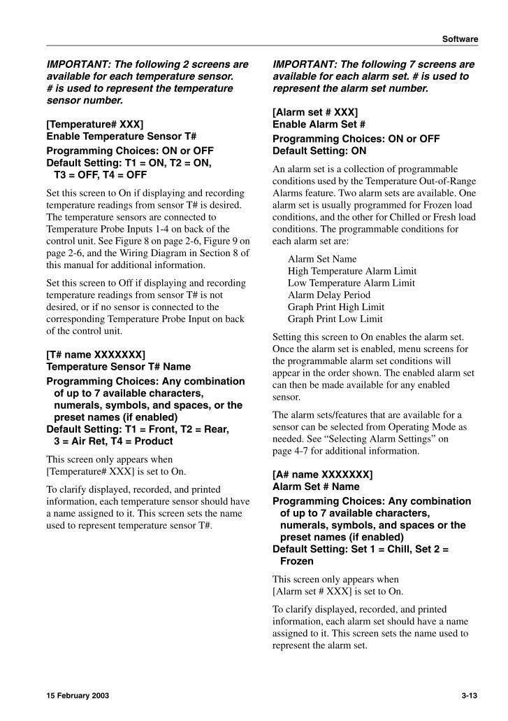
IMPORTANT: The following 2 screens are available for each temperature sensor.# is used to represent the temperature sensor number.
[Temperature# XXX]Enable Temperature Sensor T#Programming Choices: ON or OFFDefault Setting: T1 = ON, T2 = ON,
T3 = OFF, T4 = OFF
Set this screen to On if displaying and recording temperature readings from sensor T# is desired. The temperature sensors are connected to Temperature Probe Inputs 1-4 on back of the control unit. See Figure 8 on page 2-6, Figure 9 on page 2-6, and the Wiring Diagram in Section 8 of this manual for additional information.
Set this screen to Off if displaying and recording temperature readings from sensor T# is not desired, or if no sensor is connected to the corresponding Temperature Probe Input on back of the control unit.
[T# name XXXXXXX]Temperature Sensor T# NameProgramming Choices: Any combination
of up to 7 available characters, numerals, symbols, and spaces, or the preset names (if enabled)
Default Setting: T1 = Front, T2 = Rear, 3 = Air Ret, T4 = Product
This screen only appears when [Temperature# XXX] is set to On.
To clarify displayed, recorded, and printed information, each temperature sensor should have a name assigned to it. This screen sets the name used to represent temperature sensor T#.
IMPORTANT: The following 7 screens are available for each alarm set. # is used to represent the alarm set number.
[Alarm set # XXX]Enable Alarm Set #Programming Choices: ON or OFFDefault Setting: ON
An alarm set is a collection of programmable conditions used by the Temperature Out-of-Range Alarms feature. Two alarm sets are available. One alarm set is usually programmed for Frozen load conditions, and the other for Chilled or Fresh load conditions. The programmable conditions for each alarm set are:
Alarm Set NameHigh Temperature Alarm LimitLow Temperature Alarm LimitAlarm Delay PeriodGraph Print High LimitGraph Print Low Limit
Setting this screen to On enables the alarm set. Once the alarm set is enabled, menu screens for the programmable alarm set conditions will appear in the order shown. The enabled alarm set can then be made available for any enabled sensor.
The alarm sets/features that are available for a sensor can be selected from Operating Mode as needed. See “Selecting Alarm Settings” on page 4-7 for additional information.
[A# name XXXXXXX]Alarm Set # NameProgramming Choices: Any combination
of up to 7 available characters, numerals, symbols, and spaces or the preset names (if enabled)
Default Setting: Set 1 = Chill, Set 2 = Frozen
This screen only appears when [Alarm set # XXX] is set to On.
To clarify displayed, recorded, and printed information, each alarm set should have a name assigned to it. This screen sets the name used to represent the alarm set.
15 February 2003 3-13
Software
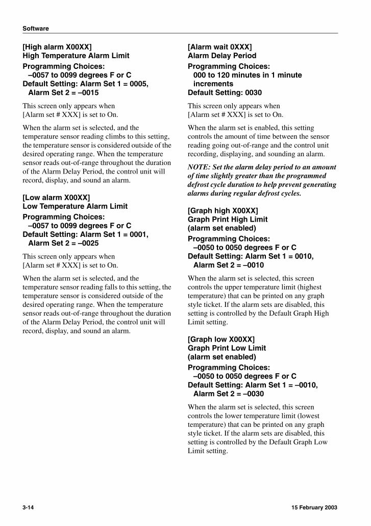
[High alarm X00XX]High Temperature Alarm LimitProgramming Choices:
–0057 to 0099 degrees F or CDefault Setting: Alarm Set 1 = 0005,
Alarm Set 2 = –0015
This screen only appears when [Alarm set # XXX] is set to On.
When the alarm set is selected, and the temperature sensor reading climbs to this setting, the temperature sensor is considered outside of the desired operating range. When the temperature sensor reads out-of-range throughout the duration of the Alarm Delay Period, the control unit will record, display, and sound an alarm.
[Low alarm X00XX]Low Temperature Alarm LimitProgramming Choices:
–0057 to 0099 degrees F or CDefault Setting: Alarm Set 1 = 0001,
Alarm Set 2 = –0025
This screen only appears when [Alarm set # XXX] is set to On.
When the alarm set is selected, and the temperature sensor reading falls to this setting, the temperature sensor is considered outside of the desired operating range. When the temperature sensor reads out-of-range throughout the duration of the Alarm Delay Period, the control unit will record, display, and sound an alarm.
[Alarm wait 0XXX]Alarm Delay PeriodProgramming Choices:
000 to 120 minutes in 1 minute increments
Default Setting: 0030
This screen only appears when [Alarm set # XXX] is set to On.
When the alarm set is enabled, this setting controls the amount of time between the sensor reading going out-of-range and the control unit recording, displaying, and sounding an alarm.
NOTE: Set the alarm delay period to an amount of time slightly greater than the programmed defrost cycle duration to help prevent generating alarms during regular defrost cycles.
[Graph high X00XX]Graph Print High Limit(alarm set enabled)Programming Choices:
–0050 to 0050 degrees F or CDefault Setting: Alarm Set 1 = 0010,
Alarm Set 2 = –0010
When the alarm set is selected, this screen controls the upper temperature limit (highest temperature) that can be printed on any graph style ticket. If the alarm sets are disabled, this setting is controlled by the Default Graph High Limit setting.
[Graph low X00XX]Graph Print Low Limit(alarm set enabled)Programming Choices:
–0050 to 0050 degrees F or CDefault Setting: Alarm Set 1 = –0010,
Alarm Set 2 = –0030
When the alarm set is selected, this screen controls the lower temperature limit (lowest temperature) that can be printed on any graph style ticket. If the alarm sets are disabled, this setting is controlled by the Default Graph Low Limit setting.
3-14 15 February 2003
Software
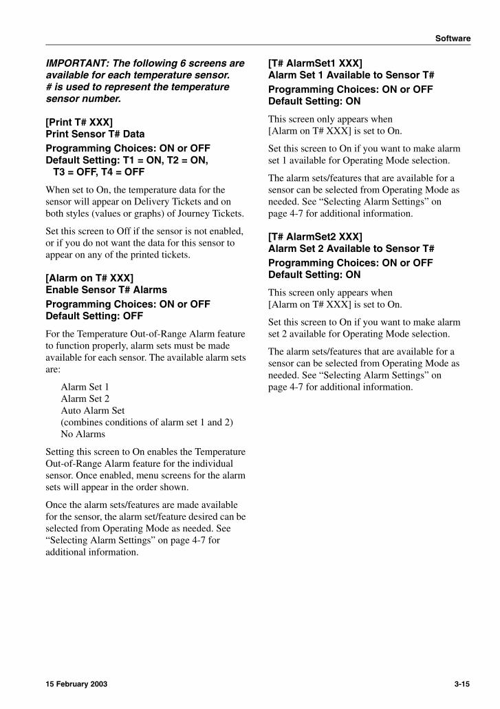
IMPORTANT: The following 6 screens are available for each temperature sensor.# is used to represent the temperature sensor number.
[Print T# XXX]Print Sensor T# DataProgramming Choices: ON or OFFDefault Setting: T1 = ON, T2 = ON,
T3 = OFF, T4 = OFF
When set to On, the temperature data for the sensor will appear on Delivery Tickets and on both styles (values or graphs) of Journey Tickets.
Set this screen to Off if the sensor is not enabled, or if you do not want the data for this sensor to appear on any of the printed tickets.
[Alarm on T# XXX]Enable Sensor T# AlarmsProgramming Choices: ON or OFFDefault Setting: OFF
For the Temperature Out-of-Range Alarm feature to function properly, alarm sets must be made available for each sensor. The available alarm sets are:
Alarm Set 1Alarm Set 2Auto Alarm Set(combines conditions of alarm set 1 and 2)No Alarms
Setting this screen to On enables the Temperature Out-of-Range Alarm feature for the individual sensor. Once enabled, menu screens for the alarm sets will appear in the order shown.
Once the alarm sets/features are made available for the sensor, the alarm set/feature desired can be selected from Operating Mode as needed. See “Selecting Alarm Settings” on page 4-7 for additional information.
[T# AlarmSet1 XXX]Alarm Set 1 Available to Sensor T#Programming Choices: ON or OFFDefault Setting: ON
This screen only appears when [Alarm on T# XXX] is set to On.
Set this screen to On if you want to make alarm set 1 available for Operating Mode selection.
The alarm sets/features that are available for a sensor can be selected from Operating Mode as needed. See “Selecting Alarm Settings” on page 4-7 for additional information.
[T# AlarmSet2 XXX]Alarm Set 2 Available to Sensor T#Programming Choices: ON or OFFDefault Setting: ON
This screen only appears when [Alarm on T# XXX] is set to On.
Set this screen to On if you want to make alarm set 2 available for Operating Mode selection.
The alarm sets/features that are available for a sensor can be selected from Operating Mode as needed. See “Selecting Alarm Settings” on page 4-7 for additional information.
15 February 2003 3-15

Software
[T# AutoAlarm XXX]Auto Alarm Set Available to Sensor T#Programming Choices: ON or OFFDefault Setting: ON
This screen only appears when [Alarm on T# XXX] is set to On.
The auto alarm feature combines the conditions from both alarm set 1 and alarm set 2. Set this screen to On if you want to make the auto alarm feature available for Operating Mode selection.
When combined with a refrigeration switch used to control alarm monitoring, this feature allows accurate monitoring of a variety of loads without any Operator interaction.
The alarm sets/features that are available for a sensor can be selected from Operating Mode as needed. See “Selecting Alarm Settings” on page 4-7 for additional information.
Example:Alarm Set 1 is set for the following Chilled or Fresh conditions:
High Temperature Alarm Limit = 5Low Temperature Alarm Limit = 1
Alarm Set 2 is set for the following Frozen conditions:
High Temperature Alarm Limit = –15Low Temperature Alarm Limit = –25
If the Auto Alarm Set feature is available and selected for a sensor, a temperature out-of-range alarm will occur when the temperature sensor is reading:
above 5between 1 and –15below –25
[T# No Alarms XXX]Disable Alarm Monitoring Available to Sensor T#Programming Choices: ON or OFFDefault Setting: ON
This screen only appears when [Alarm on T# XXX] is set to On.
The no alarms feature allows the driver or operator the ability to disable alarm monitoring for a sensor by selecting this feature from Operating Mode. Set this screen to On if you want to make the no alarms feature available for Operating Mode selection.
The alarm sets/features that are available for a sensor can be selected from Operating Mode as needed. See “Selecting Alarm Settings” on page 4-7 for additional information.
[Print Door XXX]Print Door Switch DataProgramming Choices: ON or OFFDefault Setting: OFF
When set to On, the data for the door switch (if enabled) will appear on Journey Tickets.
Set this screen to Off if a door switch is not enabled, or if you do not want the data for this system event to appear on the journey tickets.
[Print De-Ice XXX]Print DeIce (Defrost) Switch DataProgramming Choices: ON or OFFDefault Setting: OFF
When set to On, the data for the defrost switch (if enabled) will appear on Journey Tickets.
Set this screen to Off if a defrost switch is not enabled, or if you do not want the data for this system event to appear on the journey tickets.
[Print Spare XXX]Print Spare Switch DataProgramming Choices: ON or OFFDefault Setting: OFF
When set to On, the data for the spare switch (if enabled) will appear on Journey Tickets.
3-16 15 February 2003

Software
Set this screen to Off if a spare switch is not enabled, or if you do not want the data for this system event to appear on the journey tickets.
[ENG Display XXX]View Additional Screens and SettingsProgramming Choices: ON or OFFDefault Setting: OFF
NOTE: This screen is not visible on the Advanced Tab of the TranScan Settings Menu in WinTrac. This screen can only be accessed by using the Operator Keys.
Setting this screen to On allows access to the following menu screens:
[R standard][T1 cal val][T2 cal val][T3 cal val][T4 cal val][PIN number][Unit ID][Baud rate][Date][Auto Clk Adj][Clk Protect]
After initial system setup, set this screen to Off.
[R standard XXXX]Standard Calibration ConstantProgramming Choices: 0100 to 9999Default Setting: 9090
NOTE: This screen is not visible on the Advanced Tab of the TranScan Settings Menu in WinTrac. This screen can only be accessed by using the Operator Keys.
This screen only appears when [ENG Display XXX] is set to On.
This screen represents a standard calibration constant for the TranScan 2. This screen must be set to the value 9090.
IMPORTANT: The following 4 screens are available for each temperature sensor.# is used to represent the temperature sensor number.
[T# cal val XXXX]Sensor T# Standard CalibrationProgramming Choices: 0001 to 9999Default Setting: 2252
NOTE: This screen is not visible on the Advanced Tab of the TranScan Settings Menu in WinTrac. This screen can only be accessed by using the Operator Keys.
This screen only appears when [ENG Display XXX] is set to On.
This screen represents the standard calibration value for the thermistor type temperature sensors supplied with the TranScan 2 ADR system. This screen must be set to the value 2252.
NOTE: If a different sensor is used with the TranScan 2 ADR system, it must be calibrated accordingly.
[PIN number XXXX]Set Security CodeProgramming Choices:
0000 and 1111 to 7777 (recommended)Default Setting: 1111
NOTE: This screen is not visible on the Advanced Tab of the TranScan Settings Menu in WinTrac. This screen can only be accessed by using the Operator Keys.
This screen only appears when [ENG Display XXX] is set to On.
To prevent unauthorized modification of any programmable feature, entry to Configuration Mode may be password protected through the use of a 4 digit Personal Identification Number (PIN).
Entering a PIN number of 0000 disables this security feature.
NOTE: Avoid using 0, 8, or 9 in the PIN number (except for 0000).
Do not use PIN number 1212 as this sequence prints a list of all current parameter settings.
15 February 2003 3-17
Software
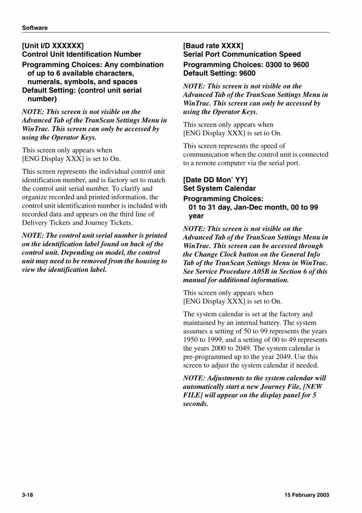
[Unit I/D XXXXXX]Control Unit Identification NumberProgramming Choices: Any combination
of up to 6 available characters, numerals, symbols, and spaces
Default Setting: (control unit serial number)
NOTE: This screen is not visible on the Advanced Tab of the TranScan Settings Menu in WinTrac. This screen can only be accessed by using the Operator Keys.
This screen only appears when [ENG Display XXX] is set to On.
This screen represents the individual control unit identification number, and is factory set to match the control unit serial number. To clarify and organize recorded and printed information, the control unit identification number is included with recorded data and appears on the third line of Delivery Tickets and Journey Tickets.
NOTE: The control unit serial number is printed on the identification label found on back of the control unit. Depending on model, the control unit may need to be removed from the housing to view the identification label.
[Baud rate XXXX]Serial Port Communication SpeedProgramming Choices: 0300 to 9600Default Setting: 9600
NOTE: This screen is not visible on the Advanced Tab of the TranScan Settings Menu in WinTrac. This screen can only be accessed by using the Operator Keys.
This screen only appears when [ENG Display XXX] is set to On.
This screen represents the speed of communication when the control unit is connected to a remote computer via the serial port.
[Date DD Mon’ YY]Set System CalendarProgramming Choices:
01 to 31 day, Jan-Dec month, 00 to 99 year
NOTE: This screen is not visible on the Advanced Tab of the TranScan Settings Menu in WinTrac. This screen can be accessed through the Change Clock button on the General Info Tab of the TranScan Settings Menu in WinTrac. See Service Procedure A05B in Section 6 of this manual for additional information.
This screen only appears when [ENG Display XXX] is set to On.
The system calendar is set at the factory and maintained by an internal battery. The system assumes a setting of 50 to 99 represents the years 1950 to 1999, and a setting of 00 to 49 represents the years 2000 to 2049. The system calendar is pre-programmed up to the year 2049. Use this screen to adjust the system calendar if needed.
NOTE: Adjustments to the system calendar will automatically start a new Journey File, [NEW FILE] will appear on the display panel for 5 seconds.
3-18 15 February 2003

Software
[Set clock hh:mm]Set System ClockProgramming Choices:
00 to 23 hours, 00 to 59 minutes
NOTE: This screen is not visible on the Advanced Tab of the TranScan Settings Menu in WinTrac. This screen can be accessed through the Change Clock button on the General Info Tab of the TranScan Settings Menu in WinTrac. See Service Procedure A05B in Section 6 of this manual for additional information.
This screen only appears when [ENG Display XXX] is set to On.
The system clock is set at the factory and maintained by an internal battery. Use this screen to adjust the system clock when the Clock Protect feature is set to On. If the clock protect feature is set to Off, the system clock may be adjusted from this screen or through Operating Mode.
The system clock includes an automatic adjustment feature for Daylight Saving Time as observed by the European Union. See “[Auto Clk Adj XXX] Automatic Clock Adjustment” on page 3-19 for additional information.
NOTE: Any adjustments to the system clock from the Configuration Menu will automatically start a new Journey File, [NEW FILE] will appear on the display panel for 5 seconds.
[Auto Clk Adj XXX]Automatic Clock AdjustmentProgramming Choices: ON or OFFDefault Setting: ON
NOTE: This screen is not visible on the Advanced Tab of the TranScan Settings Menu in WinTrac. This screen can only be accessed by using the Operator Keys.
This screen only appears when [ENG Display XXX] is set to On.
When set to On, this feature automatically adds one hour to the set time between 02:00 on the last Sunday in March to 02:00 on the last Sunday in October. This period is Daylight Saving Time for the European Union.
NOTE: Most areas of The United States observe Daylight Saving Time from 02:00 on the first Sunday in April to 02:00 on the last Sunday in October.
[Clk Protect XXX]Clock Adjustment ProtectionProgramming Choices: ON or OFFDefault Setting: OFF
NOTE: This screen is not visible on the Advanced Tab of the TranScan Settings Menu in WinTrac. This screen can only be accessed by using the Operator Keys.
This screen only appears when [ENG Display XXX] is set to On.
This feature can be used to prevent any unauthorized adjustment of the clock settings. When set to On, the only method of clock adjustment is through Configuration Mode, and entry to Configuration Mode can be password (PIN) protected.
When this feature is set to Off, the clock may be adjusted from Operating Mode as well as from Configuration Mode. See Service Procedure A05A & Service Procedure A05B in Section 6 of this manual for additional information.
15 February 2003 3-19

Software
[Vehicle XXXXXXXX]Vehicle Identification NumberProgramming Choices: Any combination
of up to 8 available characters, numerals, symbols, and spaces
Default Setting: (user defined)
This screen represents the vehicle or trailer identification number, and is commonly set to match the vehicle or trailer registration number. To clarify and organize recorded and printed information, the vehicle identification number is included with recorded data and appears on the second line of Delivery Tickets and Journey Tickets.
[Title1 XXXXXXXX]Ticket Heading (1st 8 of 16 digits)Programming Choices: Any combination
of up to 8 available characters, numerals, symbols, and spaces
Default Setting: Company
This screen represents the first half of the ticket heading. When combined with the [Title2] setting, 16 total digits are available. The ticket heading is commonly set to match the refrigerated transport company’s name. To clarify and organize printed information, the ticket heading appears on the first line of Delivery Tickets and Journey Tickets.
[Title2 XXXXXXXX]Ticket Heading (2nd 8 of 16 digits)Programming Choices: Any combination
of up to 8 available characters, numerals, symbols, and spaces
Default Setting: Name
This screen represents the second half of the ticket heading. When combined with the [Title1] setting, 16 total digits are available. The ticket heading is commonly set to match the refrigerated transport company’s name. To clarify and organize printed information, the ticket heading appears on the first line of Delivery Tickets and Journey Tickets.
Configuration Menu FlowchartFor quick reference, a flowchart of the configuration menu screens when accessed with the operator keys appears on the following page.
3-20 15 February 2003
Software
Tran
Sca
n2
Co
nfi
gu
rati
on
Mo
de
Men
uR
evis
ion
TS
2-T
410.
014
So
ftw
are
Flo
wch
art
15 February 2003 3-21

Software
3-22 15 February 2003
Section 4OperationOperator Controls . . . . . . . . . . . . . . . . . . . . .4-1
Display Panel . . . . . . . . . . . . . . . . . . . . . . .4-1Summary Display Mode . . . . . . . . . . . . .4-1Single Display Mode. . . . . . . . . . . . . . . .4-1Scroll Display Mode . . . . . . . . . . . . . . . .4-1
Display Panel Indicators . . . . . . . . . . . . . . .4-2Recording Indicator . . . . . . . . . . . . . . . .4-2System Event Indicators. . . . . . . . . . . . .4-2
Control Panel . . . . . . . . . . . . . . . . . . . . . . .4-2
Operating Mode . . . . . . . . . . . . . . . . . . . . . . .4-3Operator Keys (operating mode). . . . . . . . .4-3
Print Delivery Ticket (model T and C) . .4-3 Print Tickets (model R) . . . . . . . . . . . . .4-3 Print Journey Ticket (model T and C) . .4-3 Pause . . . . . . . . . . . . . . . . . . . . . . . . . .4-3 Enter . . . . . . . . . . . . . . . . . . . . . . . . . . .4-3 Recording Interval . . . . . . . . . . . . . . . . .4-3 Journey Ticket Style Select . . . . . . . . . .4-3 Clock/Calendar . . . . . . . . . . . . . . . . . . .4-3 Display Mode Select . . . . . . . . . . . . . . .4-3
Operating Mode Procedures. . . . . . . . . . . . .4-4Printing “Help” Tickets. . . . . . . . . . . . . . . . .4-4
Model T and C . . . . . . . . . . . . . . . . . . . .4-4Model R . . . . . . . . . . . . . . . . . . . . . . . . .4-4
Printing Delivery Tickets . . . . . . . . . . . . . . .4-5Model T and C . . . . . . . . . . . . . . . . . . . .4-5Model R . . . . . . . . . . . . . . . . . . . . . . . . .4-5
Selecting Journey Ticket Data Style . . . . . .4-5Printing Journey Tickets . . . . . . . . . . . . . . .4-6
Model T and C . . . . . . . . . . . . . . . . . . . .4-6Model R . . . . . . . . . . . . . . . . . . . . . . . . .4-6
Selecting Display Mode. . . . . . . . . . . . . . . .4-6Adjusting Recording Interval . . . . . . . . . . . .4-7Selecting Alarm Settings . . . . . . . . . . . . . . .4-7Clearing Alarms. . . . . . . . . . . . . . . . . . . . . .4-8

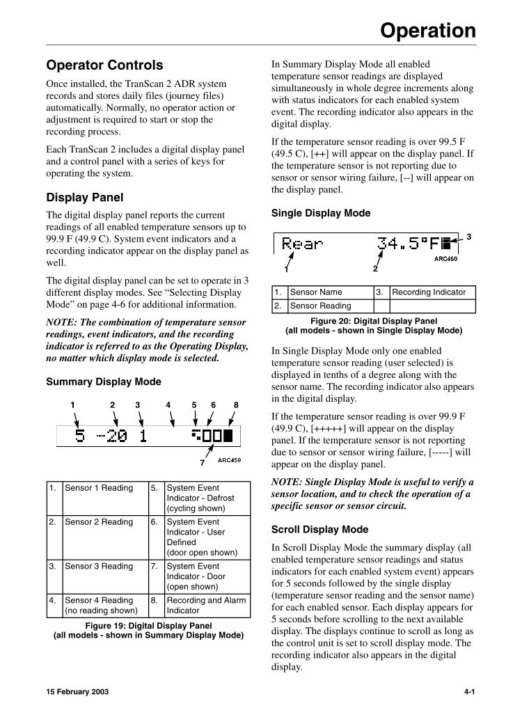
Operation
Operator ControlsOnce installed, the TranScan 2 ADR system records and stores daily files (journey files) automatically. Normally, no operator action or adjustment is required to start or stop the recording process.
Each TranScan 2 includes a digital display panel and a control panel with a series of keys for operating the system.
Display PanelThe digital display panel reports the current readings of all enabled temperature sensors up to 99.9 F (49.9 C). System event indicators and a recording indicator appear on the display panel as well.
The digital display panel can be set to operate in 3 different display modes. See “Selecting Display Mode” on page 4-6 for additional information.
NOTE: The combination of temperature sensor readings, event indicators, and the recording indicator is referred to as the Operating Display, no matter which display mode is selected.
Summary Display Mode
In Summary Display Mode all enabled temperature sensor readings are displayed simultaneously in whole degree increments along with status indicators for each enabled system event. The recording indicator also appears in the digital display.
If the temperature sensor reading is over 99.5 F (49.5 C), [++] will appear on the display panel. If the temperature sensor is not reporting due to sensor or sensor wiring failure, [--] will appear on the display panel.
Single Display Mode
In Single Display Mode only one enabled temperature sensor reading (user selected) is displayed in tenths of a degree along with the sensor name. The recording indicator also appears in the digital display.
If the temperature sensor reading is over 99.9 F (49.9 C), [+++++] will appear on the display panel. If the temperature sensor is not reporting due to sensor or sensor wiring failure, [-----] will appear on the display panel.
NOTE: Single Display Mode is useful to verify a sensor location, and to check the operation of a specific sensor or sensor circuit.
Scroll Display Mode
In Scroll Display Mode the summary display (all enabled temperature sensor readings and status indicators for each enabled system event) appears for 5 seconds followed by the single display (temperature sensor reading and the sensor name) for each enabled sensor. Each display appears for 5 seconds before scrolling to the next available display. The displays continue to scroll as long as the control unit is set to scroll display mode. The recording indicator also appears in the digital display.
1. Sensor 1 Reading 5. System Event Indicator - Defrost(cycling shown)
2. Sensor 2 Reading 6. System Event Indicator - User Defined(door open shown)
3. Sensor 3 Reading 7. System Event Indicator - Door(open shown)
4. Sensor 4 Reading(no reading shown)
8. Recording and Alarm Indicator
Figure 19: Digital Display Panel(all models - shown in Summary Display Mode)
11 2 3 4 5 6 8
7
1. Sensor Name 3. Recording Indicator
2. Sensor Reading
Figure 20: Digital Display Panel(all models - shown in Single Display Mode)
1 2
3
15 February 2003 4-1
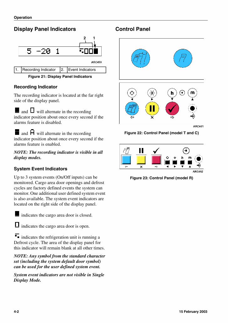
Operation
Display Panel Indicators
Recording Indicator
The recording indicator is located at the far right side of the display panel.
and will alternate in the recording indicator position about once every second if the alarms feature is disabled.
and will alternate in the recording indicator position about once every second if the alarms feature is enabled.
NOTE: The recording indicator is visible in all display modes.
System Event Indicators
Up to 3 system events (On/Off inputs) can be monitored. Cargo area door openings and defrost cycles are factory defined events the system can monitor. One additional user defined system event is also available. The system event indicators are located on the right side of the display panel.
indicates the cargo area door is closed.
indicates the cargo area door is open.
indicates the refrigeration unit is running a Defrost cycle. The area of the display panel for this indicator will remain blank at all other times.
NOTE: Any symbol from the standard character set (including the system default door symbol) can be used for the user defined system event.
System event indicators are not visible in Single Display Mode.
Control Panel
Figure 22: Control Panel (model T and C)
Figure 23: Control Panel (model R)
1. Recording Indicator 2. Event Indicators
Figure 21: Display Panel Indicators
12
4-2 15 February 2003
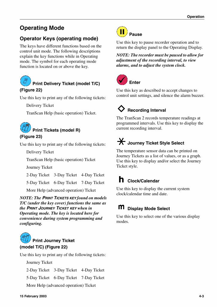
Operation
Operating Mode
Operator Keys (operating mode)The keys have different functions based on the control unit mode. The following descriptions explain the key functions while in Operating mode. The symbol for each operating mode function is located on or above the key.
Print Delivery Ticket (model T/C)(Figure 22)
Use this key to print any of the following tickets:
Delivery Ticket
TranScan Help (basic operation) Ticket.
Print Tickets (model R)(Figure 23)
Use this key to print any of the following tickets:
Delivery Ticket
TranScan Help (basic operation) Ticket
Journey Ticket
2-Day Ticket 3-Day Ticket 4-Day Ticket
5-Day Ticket 6-Day Ticket 7-Day Ticket
More Help (advanced operation) Ticket
NOTE: The PRINT TICKETS KEY found on models T/C (under the key cover) functions the same as the PRINT JOURNEY TICKET KEY when in Operating mode. The key is located here for convenience during system programming and configuring.
Print Journey Ticket(model T/C) (Figure 22)
Use this key to print any of the following tickets:
Journey Ticket
2-Day Ticket 3-Day Ticket 4-Day Ticket
5-Day Ticket 6-Day Ticket 7-Day Ticket
More Help (advanced operation) Ticket
Pause
Use this key to pause recorder operation and to return the display panel to the Operating Display.
NOTE: The recorder must be paused to allow for adjustment of the recording interval, to view alarms, and to adjust the system clock.
Enter
Use this key as described to accept changes to control unit settings, and silence the alarm buzzer.
Recording Interval
The TranScan 2 records temperature readings at programmed intervals. Use this key to display the current recording interval.
Journey Ticket Style Select
The temperature sensor data can be printed on Journey Tickets as a list of values, or as a graph. Use this key to display and/or select the Journey Ticket style.
Clock/Calendar
Use this key to display the current system clock/calendar time and date.
Display Mode Select
Use this key to select one of the various display modes.
15 February 2003 4-3

Operation
Operating Mode ProceduresNOTE: Additional procedures can be found in Section 6 of this manual.
Printing “Help” TicketsTwo different Help Tickets are available with each TranScan 2 ADR. The “TranScan Help” ticket covers most commonly used basic operations. The “More Help” ticket covers print and display options available.
Figure 24: Help and More Help Tickets
NOTE: If the printer is exposed to moisture, it should be allowed to dry completely before use.
To ensure on demand printing, a spare printer paper roll should be available at all times.
The type of ticket displayed will begin printing in 3 seconds or immediately upon pressing . The control unit will return to the Operating Display when printing is complete.
Press any key to cancel printing, [Abandoned] will briefly appear on the display panel, and the control unit will return to the Operating Display.
Model T and C(Figure 22)
From the Operating Display, press as needed to display [TranScan Help].
From the Operating Display, press or as needed to display [More Help].
Model R(Figure 23)
From the Operating Display, press as needed to display [TranScan Help] or [More Help].
4-4 15 February 2003
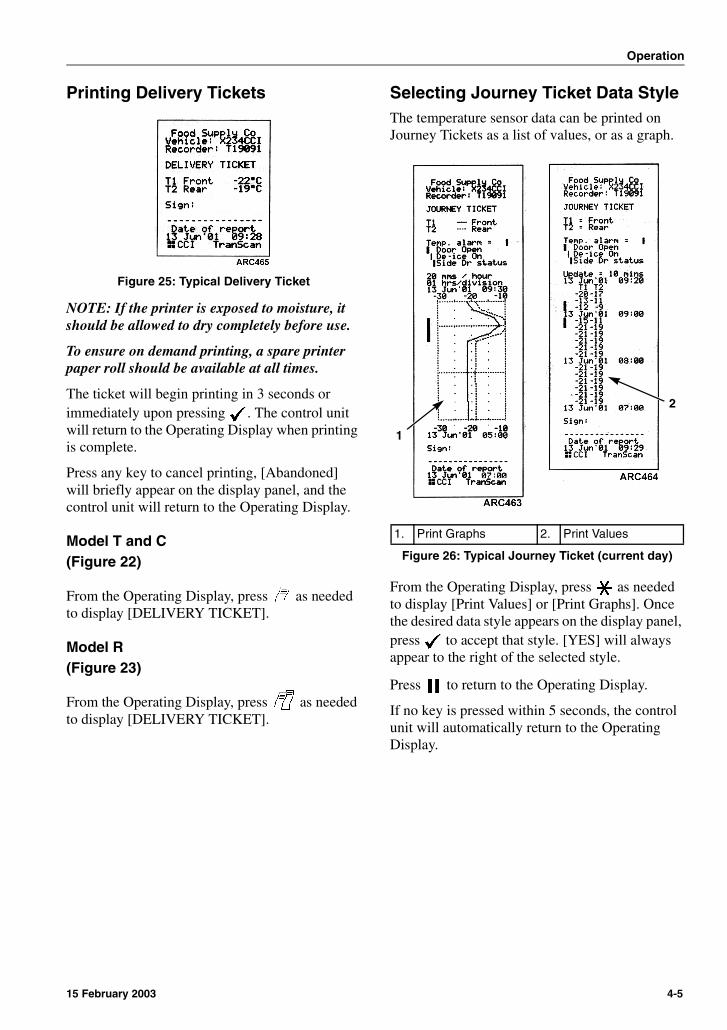
Operation
Printing Delivery Tickets
Figure 25: Typical Delivery Ticket
NOTE: If the printer is exposed to moisture, it should be allowed to dry completely before use.
To ensure on demand printing, a spare printer paper roll should be available at all times.
The ticket will begin printing in 3 seconds or immediately upon pressing . The control unit will return to the Operating Display when printing is complete.
Press any key to cancel printing, [Abandoned] will briefly appear on the display panel, and the control unit will return to the Operating Display.
Model T and C(Figure 22)
From the Operating Display, press as needed to display [DELIVERY TICKET].
Model R(Figure 23)
From the Operating Display, press as needed to display [DELIVERY TICKET].
Selecting Journey Ticket Data StyleThe temperature sensor data can be printed on Journey Tickets as a list of values, or as a graph.
From the Operating Display, press as needed to display [Print Values] or [Print Graphs]. Once the desired data style appears on the display panel, press to accept that style. [YES] will always appear to the right of the selected style.
Press to return to the Operating Display.
If no key is pressed within 5 seconds, the control unit will automatically return to the Operating Display.
1. Print Graphs 2. Print Values
Figure 26: Typical Journey Ticket (current day)
1
2
15 February 2003 4-5
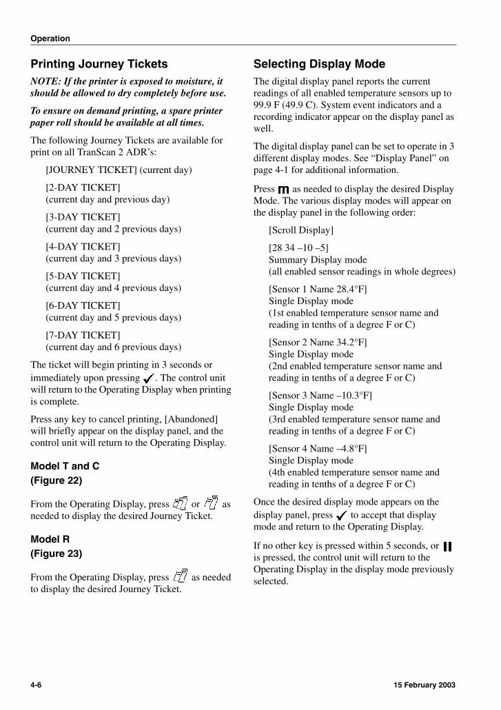
Operation
Printing Journey TicketsNOTE: If the printer is exposed to moisture, it should be allowed to dry completely before use.
To ensure on demand printing, a spare printer paper roll should be available at all times.
The following Journey Tickets are available for print on all TranScan 2 ADR’s:
[JOURNEY TICKET] (current day)
[2-DAY TICKET](current day and previous day)
[3-DAY TICKET](current day and 2 previous days)
[4-DAY TICKET](current day and 3 previous days)
[5-DAY TICKET](current day and 4 previous days)
[6-DAY TICKET](current day and 5 previous days)
[7-DAY TICKET](current day and 6 previous days)
The ticket will begin printing in 3 seconds or immediately upon pressing . The control unit will return to the Operating Display when printing is complete.
Press any key to cancel printing, [Abandoned] will briefly appear on the display panel, and the control unit will return to the Operating Display.
Model T and C(Figure 22)
From the Operating Display, press or as needed to display the desired Journey Ticket.
Model R(Figure 23)
From the Operating Display, press as needed to display the desired Journey Ticket.
Selecting Display ModeThe digital display panel reports the current readings of all enabled temperature sensors up to 99.9 F (49.9 C). System event indicators and a recording indicator appear on the display panel as well.
The digital display panel can be set to operate in 3 different display modes. See “Display Panel” on page 4-1 for additional information.
Press as needed to display the desired Display Mode. The various display modes will appear on the display panel in the following order:
[Scroll Display]
[28 34 –10 –5]Summary Display mode(all enabled sensor readings in whole degrees)
[Sensor 1 Name 28.4°F]Single Display mode(1st enabled temperature sensor name and reading in tenths of a degree F or C)
[Sensor 2 Name 34.2°F]Single Display mode(2nd enabled temperature sensor name and reading in tenths of a degree F or C)
[Sensor 3 Name –10.3°F]Single Display mode(3rd enabled temperature sensor name and reading in tenths of a degree F or C)
[Sensor 4 Name –4.8°F]Single Display mode(4th enabled temperature sensor name and reading in tenths of a degree F or C)
Once the desired display mode appears on the display panel, press to accept that display mode and return to the Operating Display.
If no other key is pressed within 5 seconds, or is pressed, the control unit will return to the Operating Display in the display mode previously selected.
4-6 15 February 2003
Operation
Adjusting Recording IntervalThe recording interval represents the rate at which the recordings are made.
From the Operating Display, press once, [PAUSING] will appear on the display panel.
Press as needed to adjust the recording interval to 1, 2, 5, 10, 15, 30, or 60 minute preset intervals.
Once the desired interval appears on the display panel, press to accept the change. The control unit will automatically restart operation and return to the Operating Display.
If no other key is pressed within 15 seconds, or is pressed, the control unit will automatically
restart operation, return to the previous recording interval, and return to the Operating Display.
NOTE: Adjustments to the recording interval will automatically start a new Journey File, [NEW FILE] will appear on the display panel for 5 seconds.
The recording interval may be adjusted to a time other than the programed presets. See “[min/update 00XX] Set Recording Interval” on page 3-9 for additional information.
Selecting Alarm Settings
From the Operating Display, press once, [PAUSING] will appear on the display panel.
Press to check the current alarm settings.
If the alarms feature for all enabled sensors is turned Off, [No alarms] will appear in the display panel.
Press as needed to view the alarm sets (conditions) available for a sensor [SensorName AlarmSetName]. [YES] will appear to the right of the currently selected sensor/alarm set combination. The possible alarm sets are:
[AlarmSetName] (alarm set 1)
[AlarmSetName] (alarm set 2)
[Auto] (combines alarm set 1 and 2)
[Noalm] (alarm monitoring disabled)
To select one of the available sensor/alarm set combinations, press as needed to display the desired sensor/alarm set combination. Press to accept the sensor/alarm set combination displayed. [YES] will appear to the right of the currently selected sensor/alarm set combination. Selecting [Noalm] disables the temperature out-of-range alarm feature for the sensor.
One of the Alarm Sets, Auto, or NoAlm must be selected [YES] for each enabled sensor at all times.
NOTE: Depending on system configuration, more than one alarm set may be available for a sensor, and some sensors may have no alarm sets available to them.
For additional information on configuring the alarm feature, see the various alarm settings in “Configuration Menu” on page 3-8.
If no other key is pressed within 15 seconds, or is pressed, the control unit will automatically
restart operation, and return to the Operating Display.
15 February 2003 4-7
Operation
Clearing AlarmsIf the alarms feature is enabled, and a temperature out-of-range alarm occurs:
An audible alarm inside the control unit will sound
An alarm light (if installed) will illuminate
The temperature sensor reading for the offending sensor will flash On and Off
Press to silence the audible alarm, [Alarm accepted] will appear on the display panel. The alarm light (if installed) will remain illuminated, and the offending sensor reading will continue to flash until the sensor temperature reading returns to within its programmed operating range.
Alarms can be manually reset without interrupting the recording process by:
Selecting No Alarms for the offending sensor sensor in Operating Mode if available. See “Selecting Alarm Settings” on page 4-7 of this manual for additional information.
Disabling the alarm for the offending sensor in Configuration Mode. See “[Alarm on T# XXX] Enable Sensor T# Alarms” on page 3-15 for additional information.
NOTE: If a refrigeration On/Off signal switch is included in the system, alarms will reset when the refrigeration system is switched Off for a period of time longer than the Set Extended Alarm Monitoring Period.
4-8 15 February 2003

Section 5DiagnosticsSoftware Revisions . . . . . . . . . . . . . . . . . . . .5-1
Electrostatic Discharge (ESD) . . . . . . . . . . .5-1
Temperature Out-of-Range Alarms . . . . . . .5-1
Troubleshooting Suggestions . . . . . . . . . . .5-3
TranScan 2 System TroubleshootingTable . . . . . . . . . . . . . . . . . . . . . . . . . . . . . .5-3

Diagnostics
This section is a troubleshooting aid. It is designed to help isolate a problem via Temperature Out-of-Range Alarms or other symptoms and refer the technician to the appropriate actions necessary to complete the repair.Section 6 of this manual contains many Service Procedures necessary to successfully accomplish a variety of service tasks. The procedures must be followed exactly, for in many cases failure to do so will result in an incomplete or improper repair. Service Procedures are referenced by Procedure Number rather than section and page number to facilitate future updates and additions.
Software RevisionsThere may be several revisions of software used with the TranScan 2 ADR system. In addition, upgrade software may be made available that incorporates new features. It is very important that the correct revision of software be installed in the control unit.
To check the current software revision, see Service Procedure A06A in Section 6 of this manual.
Always consult Service Information A16A “Software (PROM Chip) interchange and Service Part Numbers” in Section 7 of this manual when replacing software or control units.
Electrostatic Discharge (ESD)As with other similar electronic devices, the Tran Scan 2 control unit is vulnerable to damage from Electrostatic Discharge (ESD). This damage is not always immediately apparent. As a result of ESD, a circuit can be damaged but may continue to operate temporarily only to fail later.
A grounded wrist strap should always be used when handling a control unit circuit board or PROM Chip that is not grounded to the refrigeration unit. The control unit circuit board and PROM Chip should always be stored and shipped in an anti-static bag and protective packaging.
For additional information on electrostatic discharge, refer to the Electrostatic Discharge Training Guide (TK 40282) and Service Procedure A12A in Section 6 of this manual.
Temperature Out-of-Range AlarmsThe Temperature Out-of-Range Alarms feature records, displays, and sounds an alarm if a temperature sensor reading raises above or drops below the desired temperature range.
Keep the following information in mind when diagnosing temperature out-of-range alarm issues:
• Configuration mode settings determine when to start and stop monitoring the system for alarms. The system can be configured to start and stop monitoring for alarms manually, or automatically by incorporating a refrigeration switch. These settings are different then the recording start and stop times.
See “Enable Temperate Out-of-Range Alarm” and “Enable Extended Alarm Monitoring” beginning on page 3-11 for additional information.
• Configuration mode settings determine the conditions for the available alarm sets.
See “Enable Alarm Set#” beginning on page 3-13 for additional information.
• Configuration mode settings determine which sensors are monitored for alarms. Any, all, or none of the available sensors can be monitored.
See “Enable Sensor T# Alarms” beginning on page 3-15 for additional information.
• Configuration mode settings determine which alarm sets (conditions) are available for each sensor being monitored. In addition to alarm sets, 1 and 2, Auto Alarm (alarm set 1 and 2 conditions combined) and No Alarm (alarm disabled) can be made available for a sensor. Once the alarm sets are made available to a sensor, they can be easily selected by the Driver or Operator as load types (fresh, frozen, ambient) change.
15 February 2003 5-1
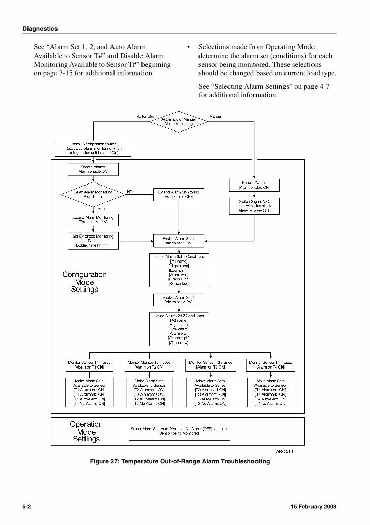
Diagnostics
See “Alarm Set 1, 2, and Auto Alarm Available to Sensor T#” and Disable Alarm Monitoring Available to Sensor T#” beginning on page 3-15 for additional information.
• Selections made from Operating Mode determine the alarm set (conditions) for each sensor being monitored. These selections should be changed based on current load type.
See “Selecting Alarm Settings” on page 4-7 for additional information.
Figure 27: Temperature Out-of-Range Alarm Troubleshooting
5-2 15 February 2003
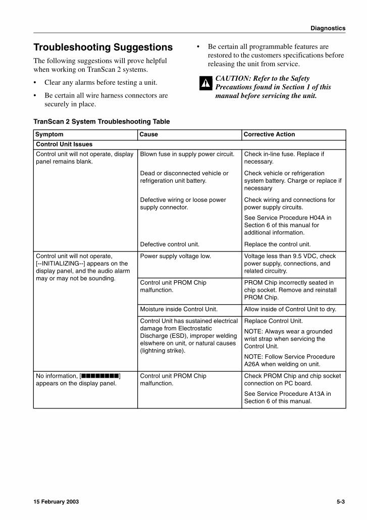
Diagnostics
Troubleshooting SuggestionsThe following suggestions will prove helpful when working on TranScan 2 systems.
• Clear any alarms before testing a unit.
• Be certain all wire harness connectors are securely in place.
• Be certain all programmable features are restored to the customers specifications before releasing the unit from service.
CAUTION: Refer to the Safety Precautions found in Section 1 of this manual before servicing the unit.
TranScan 2 System Troubleshooting Table
Symptom Cause Corrective Action
Control Unit Issues
Control unit will not operate, display panel remains blank.
Blown fuse in supply power circuit. Check in-line fuse. Replace if necessary.
Dead or disconnected vehicle or refrigeration unit battery.
Check vehicle or refrigeration system battery. Charge or replace if necessary
Defective wiring or loose power supply connector.
Check wiring and connections for power supply circuits.
See Service Procedure H04A in Section 6 of this manual for additional information.
Defective control unit. Replace the control unit.
Control unit will not operate, [--INITIALIZING--] appears on the display panel, and the audio alarm may or may not be sounding.
Power supply voltage low. Voltage less than 9.5 VDC, check power supply, connections, and related circuitry.
Control unit PROM Chip malfunction.
PROM Chip incorrectly seated in chip socket. Remove and reinstall PROM Chip.
Moisture inside Control Unit. Allow inside of Control Unit to dry.
Control Unit has sustained electrical damage from Electrostatic Discharge (ESD), improper welding elswhere on unit, or natural causes (lightning strike).
Replace Control Unit.
NOTE: Always wear a grounded wrist strap when servicing the Control Unit.
NOTE: Follow Service Procedure A26A when welding on unit.
No information, [��������] appears on the display panel.
Control unit PROM Chip malfunction.
Check PROM Chip and chip socket connection on PC board.
See Service Procedure A13A in Section 6 of this manual.
15 February 2003 5-3
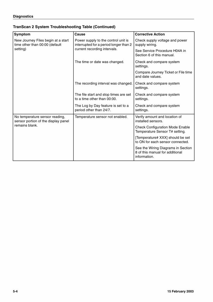
Diagnostics
New Journey Files begin at a start time other than 00:00 (default setting)
Power supply to the control unit is interrupted for a period longer than 2 current recording intervals.
Check supply voltage and power supply wiring.
See Service Procedure H04A in Section 6 of this manual.
The time or date was changed. Check and compare system settings.
Compare Journey Ticket or File time and date values.
The recording interval was changed. Check and compare system settings.
The file start and stop times are set to a time other than 00:00.
Check and compare system settings.
The Log by Day feature is set to a period other than 24/7.
Check and compare system settings.
No temperature sensor reading, sensor portion of the display panel remains blank.
Temperature sensor not enabled. Verify amount and location of installed sensors.
Check Configuration Mode Enable Temperature Sensor T# setting.
[Temperature# XXX] should be set to ON for each sensor connected.
See the Wiring Diagrams in Section 8 of this manual for additional information.
TranScan 2 System Troubleshooting Table (Continued)
Symptom Cause Corrective Action
5-4 15 February 2003
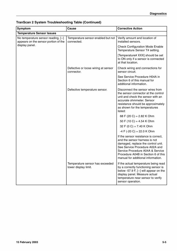
Diagnostics
Temperature Sensor Issues
No temperature sensor reading, [--] appears on the sensor portion of the display panel.
Temperature sensor enabled but not connected.
Verify amount and location of installed sensors.
Check Configuration Mode Enable Temperature Sensor T# setting.
[Temperature# XXX] should be set to ON only if a sensor is connected at that location.
Defective or loose wiring at sensor connector.
Check wiring and connections for sensor circuit.
See Service Procedure H04A in Section 6 of this manual for additional information.
Defective temperature sensor. Disconnect the sensor wires from the sensor connector at the control unit and check the sensor with an accurate ohmmeter. Sensor resistance should be approximately as shown for the temperatures listed:
68 F (20 C) = 2.82 K Ohm
50 F (10 C) = 4.54 K Ohm
32 F (0 C) = 7.40 K Ohm
-4 F (-20 C) = 22.0 K Ohm
If the sensor resistance is correct, and the sensor harness is not damaged, replace the control unit. See Service Procedure A02A and Service Procedure A04A & Service Procedure A04B in Section 6 of this manual for additional information.
Temperature sensor has exceeded lower display limit.
If the actual temperature being read by a correctly functioning sensor is below -57.9 F, [--] will appear on the display panel. Measure actual temperature near sensor to verify sensor operation.
TranScan 2 System Troubleshooting Table (Continued)
Symptom Cause Corrective Action
15 February 2003 5-5
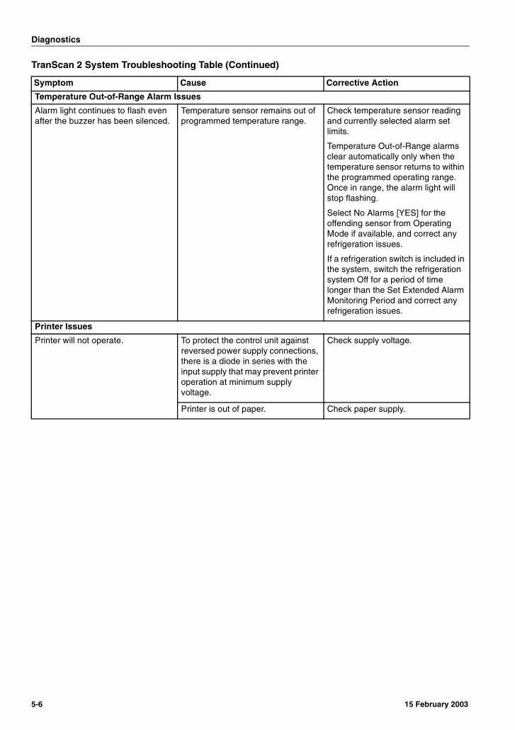
Diagnostics
Temperature Out-of-Range Alarm Issues
Alarm light continues to flash even after the buzzer has been silenced.
Temperature sensor remains out of programmed temperature range.
Check temperature sensor reading and currently selected alarm set limits.
Temperature Out-of-Range alarms clear automatically only when the temperature sensor returns to within the programmed operating range. Once in range, the alarm light will stop flashing.
Select No Alarms [YES] for the offending sensor from Operating Mode if available, and correct any refrigeration issues.
If a refrigeration switch is included in the system, switch the refrigeration system Off for a period of time longer than the Set Extended Alarm Monitoring Period and correct any refrigeration issues.
Printer Issues
Printer will not operate. To protect the control unit against reversed power supply connections, there is a diode in series with the input supply that may prevent printer operation at minimum supply voltage.
Check supply voltage.
Printer is out of paper. Check paper supply.
TranScan 2 System Troubleshooting Table (Continued)
Symptom Cause Corrective Action
5-6 15 February 2003

Section 6Service ProceduresControl Unit ProceduresA02A Recording Existing Control Unit SettingsA03A Setting Display and Print OptionsA04A System Setup - Using the Control Unit KeysA04B System Setup - Using a Remote ComputerA05A Adjusting the Calender/Clock - Using the Control Unit KeysA05B Adjusting the Calender/Clock - Using a Remote ComputerA06A Checking Software Revision - Soft ResetA12A Electrostatic Discharge (ESD) ProceduresA13A Changing Software (PROM Chip)A26A Welding on Units Equipped with TranScan 2 Control UnitsA50A Downloading Files in Control Unit MemoryA51A Printing Journey Tickets (files) in Control Unit MemoryA60A Replacing Printer PaperA61A Replacing Printer RibbonA70A Comparing Control Unit Settings Using the Signature Feature
Micellaneous ProceduresH04A Checking Harness Continuity

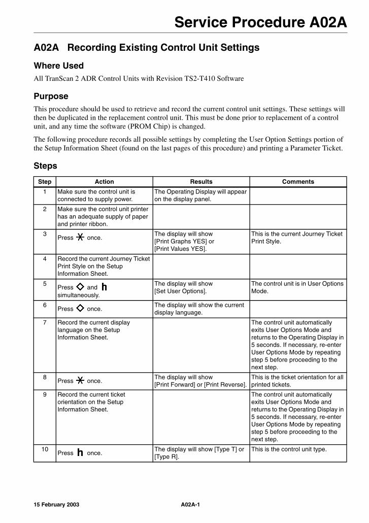
Service Procedure A02A
A02A Recording Existing Control Unit Settings
Where UsedAll TranScan 2 ADR Control Units with Revision TS2-T410 Software
PurposeThis procedure should be used to retrieve and record the current control unit settings. These settings will then be duplicated in the replacement control unit. This must be done prior to replacement of a control unit, and any time the software (PROM Chip) is changed.
The following procedure records all possible settings by completing the User Option Settings portion of the Setup Information Sheet (found on the last pages of this procedure) and printing a Parameter Ticket.
Steps
Step Action Results Comments
1 Make sure the control unit is connected to supply power.
The Operating Display will appear on the display panel.
2 Make sure the control unit printer has an adequate supply of paper and printer ribbon.
3Press once.
The display will show [Print Graphs YES] or [Print Values YES].
This is the current Journey Ticket Print Style.
4 Record the current Journey Ticket Print Style on the Setup Information Sheet.
5Press and simultaneously.
The display will show [Set User Options].
The control unit is in User Options Mode.
6Press once.
The display will show the current display language.
7 Record the current display language on the Setup Information Sheet.
The control unit automatically exits User Options Mode and returns to the Operating Display in 5 seconds. If necessary, re-enter User Options Mode by repeating step 5 before proceeding to the next step.
8Press once.
The display will show [Print Forward] or [Print Reverse].
This is the ticket orientation for all printed tickets.
9 Record the current ticket orientation on the Setup Information Sheet.
The control unit automatically exits User Options Mode and returns to the Operating Display in 5 seconds. If necessary, re-enter User Options Mode by repeating step 5 before proceeding to the next step.
10Press once.
The display will show [Type T] or [Type R].
This is the control unit type.
A02A-115 February 2003

Service Procedure A02A
11 Record the control unit type on the Setup Information Sheet.
The control unit automatically exits User Options Mode and returns to the Operating Display in 5 seconds. If necessary, re-enter User Options Mode by repeating step 5 before proceeding to the next step.
12Press once.
The display will show [Temperature °F] or [Temperature °C].
This is the current display unit of measure setting.
13 Record the current display unit of measure setting on the Setup Information Sheet.
14 Allow the control unit to exit User Options Mode and return to the Operating Display.
15Press and simultaneously
The display will show [Enter PIN code].
NOTE: If the Pin code security feature has been disabled (set to 0000), the last configuration menu screen viewed will appear on the display panel.
A valid Security Code (set to a PIN other than 0000) must be used to print a Parameter Ticket. Set a temporary PIN code through the Configuration Mode [PIN number XXXX] screen (1111 recommended), exit Configuration Mode, and repeat this step.
16 Enter the PIN code. The display will show [Start time hh:mm]
This is the first configuration menu screen.
17Press or repeatedly until the [ENG Display] screen appears.
The display will show [ENG Display XXX].
18 If the [ENG Display] screen is set to ON, proceed to step 19.
If the [ENG Display] screen is set
to OFF, press to set the screen to ON.
The display will show [ENG Display ON].
Setting this screen to On exposes additional configuration menu screens. The settings of the additional screens should be recorded.
19Press to exit configuration mode.
The Operating Display will appear on the display panel.
20Press and simultaneously
The display will show [Enter PIN code].
21Press , , , to enter the print Parameter Ticket code 1212.
The display panel will show [Print parameters] and the printer will begin printing the current configuration menu screen settings in order on a single Parameter Ticket.
When finished, the printer will stop and the Operating Display will appear on the display panel.
Attach the Parameter Ticket to the Setup Information Sheet.
Step Action Results Comments
A02A-2 15 February 2003
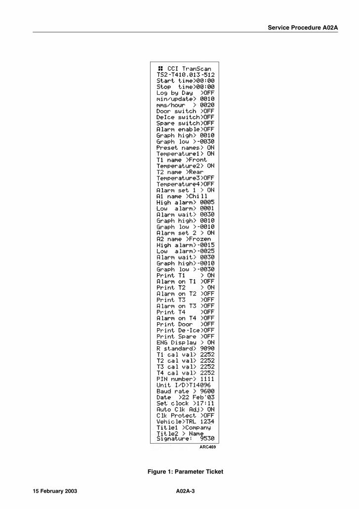
Service Procedure A02A
Figure 1: Parameter Ticket
A02A-315 February 2003

Service Procedure A02A
Setup Information SheetTranScan 2 Control Units with Revision TS2-T410 Software
User Option Settings
User Option Display Default Setting Recorded Setting
Journey Ticket print style [Print Graphs XXX]or
[Print Values XXX]
Print Values
Display Language [current language] English
Ticket Orientation [Print Forward]or
[Print Reverse]
Print Reverse(Model T and C)
Print Forward(Model R)
Control Unit Type [Type T] or [Type R] (defined by model)
NOTE: Model T and C use the [Type T] setting.
Display Unit of Measure [Temperature °F]or
[Temperature °C]
Temperature °C
Configuration Mode Settings (parameters)
Menu Screen Display Default Setting Recorded Setting
NOTE: Complete this table manually if the control unit is unable to print a Parameter Ticket
Set Recording Start Time [Start time hh:mm] 00:00
Set Recording Stop Time [Stop time hh:mm] 00:00
Select Weekly Recording Schedule [Log by day XXX] OFF
Set Days for Weekly Recording Schedule
[Day Code XXXXXXX] CCCCCCC
Set Recording Interval [min/update 00XX] 0010
Set Graph Print Density [mms/hour 00XX] 0020
Enable System Event - Door [Door switch XXX] OFF
Reverse Door Switch Signal [Door reverse XXX] OFF
Enable System Event - DeIce (Defrost) [DeIce switch XXX] OFF
Reverse DeIce (Defrost) Switch Signal
[DIce reverse XXX] ON
Enable System Event - Spare [Spare switch XXX] OFF
Reverse Spare Switch Signal [Spare reverse XXX] OFF
Spare Switch Name [Spr name XXXXXXX] (user defined)
Spare Switch Event Indicator Symbol
[Spare symbol X] (space = door symbol)
A02A-4 15 February 2003
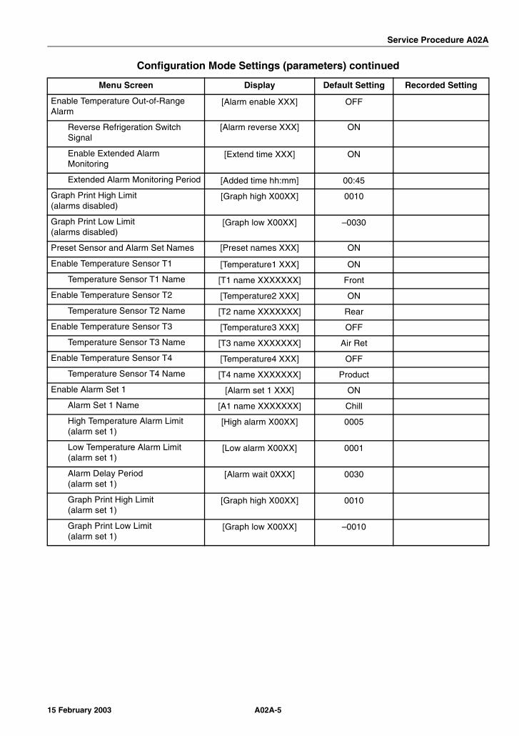
Service Procedure A02A
Enable Temperature Out-of-Range Alarm
[Alarm enable XXX] OFF
Reverse Refrigeration Switch Signal
[Alarm reverse XXX] ON
Enable Extended Alarm Monitoring
[Extend time XXX] ON
Extended Alarm Monitoring Period [Added time hh:mm] 00:45
Graph Print High Limit(alarms disabled)
[Graph high X00XX] 0010
Graph Print Low Limit(alarms disabled)
[Graph low X00XX] –0030
Preset Sensor and Alarm Set Names [Preset names XXX] ON
Enable Temperature Sensor T1 [Temperature1 XXX] ON
Temperature Sensor T1 Name [T1 name XXXXXXX] Front
Enable Temperature Sensor T2 [Temperature2 XXX] ON
Temperature Sensor T2 Name [T2 name XXXXXXX] Rear
Enable Temperature Sensor T3 [Temperature3 XXX] OFF
Temperature Sensor T3 Name [T3 name XXXXXXX] Air Ret
Enable Temperature Sensor T4 [Temperature4 XXX] OFF
Temperature Sensor T4 Name [T4 name XXXXXXX] Product
Enable Alarm Set 1 [Alarm set 1 XXX] ON
Alarm Set 1 Name [A1 name XXXXXXX] Chill
High Temperature Alarm Limit(alarm set 1)
[High alarm X00XX] 0005
Low Temperature Alarm Limit(alarm set 1)
[Low alarm X00XX] 0001
Alarm Delay Period(alarm set 1)
[Alarm wait 0XXX] 0030
Graph Print High Limit(alarm set 1)
[Graph high X00XX] 0010
Graph Print Low Limit(alarm set 1)
[Graph low X00XX] –0010
Configuration Mode Settings (parameters) continued
Menu Screen Display Default Setting Recorded Setting
A02A-515 February 2003

Service Procedure A02A
Enable Alarm Set 2 [Alarm set 2 XXX] ON
Alarm Set 2 Name [A2 name XXXXXXX] Frozen
High Temperature Alarm Limit(alarm set 2)
[High alarm X00XX] –0015
Low Temperature Alarm Limit(alarm set 2)
[Low alarm X00XX] –0025
Alarm Delay Period(alarm set 2)
[Alarm wait 0XXX] 0030
Graph Print High Limit(alarm set 2)
[Graph high X00XX] –0010
Graph Print Low Limit(alarm set 2)
[Graph low X00XX] –0030
Print Sensor T1 Data [Print T1 XXX] ON
Enable Sensor T1 Alarms [Alarm on T1 XXX] OFF
Alarm Set 1 Available to Sensor T1
[T1 AlarmSet1 XXX] ON
Alarm Set 2 Available to Sensor T1
[T1 AlarmSet2 XXX] ON
Auto Alarm Set Available to Sensor T1
[T1 AutoAlarm XXX] ON
Disable Alarm Monitoring Available to Sensor T1
[T1 No Alarms XXX] ON
Print Sensor T2 Data [Print T2 XXX] ON
Enable Sensor T2 Alarms [Alarm on T2 XXX] OFF
Alarm Set 1 Available to Sensor T2
[T2 AlarmSet1 XXX] ON
Alarm Set 2 Available to Sensor T2
[T2 AlarmSet2 XXX] ON
Auto Alarm Set Available to Sensor T2
[T2 AutoAlarm XXX] ON
Disable Alarm Monitoring Available to Sensor T2
[T2 No Alarms XXX] ON
Print Sensor T3 Data [Print T3 XXX] OFF
Enable Sensor T3 Alarms [Alarm on T3 XXX] OFF
Alarm Set 1 Available to Sensor T3
[T3 AlarmSet1 XXX] ON
Alarm Set 2 Available to Sensor T3
[T3 AlarmSet2 XXX] ON
Auto Alarm Set Available to Sensor T3
[T3 AutoAlarm XXX] ON
Disable Alarm Monitoring Available to Sensor T3
[T3 No Alarms XXX] ON
Configuration Mode Settings (parameters) continued
Menu Screen Display Default Setting Recorded Setting
A02A-6 15 February 2003
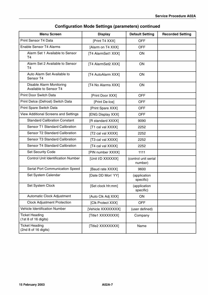
Service Procedure A02A
Print Sensor T4 Data [Print T4 XXX] OFF
Enable Sensor T4 Alarms [Alarm on T4 XXX] OFF
Alarm Set 1 Available to Sensor T4
[T4 AlarmSet1 XXX] ON
Alarm Set 2 Available to Sensor T4
[T4 AlarmSet2 XXX] ON
Auto Alarm Set Available to Sensor T4
[T4 AutoAlarm XXX] ON
Disable Alarm Monitoring Available to Sensor T4
[T4 No Alarms XXX] ON
Print Door Switch Data [Print Door XXX] OFF
Print DeIce (Defrost) Switch Data [Print De-Ice] OFF
Print Spare Switch Data [Print Spare XXX] OFF
View Additional Screens and Settings [ENG Display XXX] OFF
Standard Calibration Constant [R standard XXXX] 9090
Sensor T1 Standard Calibration [T1 cal val XXXX] 2252
Sensor T2 Standard Calibration [T2 cal val XXXX] 2252
Sensor T3 Standard Calibration [T3 cal val XXXX] 2252
Sensor T4 Standard Calibration [T4 cal val XXXX] 2252
Set Security Code [PIN number XXXX] 1111
Control Unit Identification Number [Unit I/D XXXXXX] (control unit serial number)
Serial Port Communication Speed [Baud rate XXXX] 9600
Set System Calendar [Date DD Mon’ YY] (application specific)
Set System Clock [Set clock hh:mm] (application specific)
Automatic Clock Adjustment [Auto Clk Adj XXX] ON
Clock Adjustment Protection [Clk Protect XXX] OFF
Vehicle Identification Number [Vehicle XXXXXXXX] (user defined)
Ticket Heading(1st 8 of 16 digits)
[Title1 XXXXXXXX] Company
Ticket Heading(2nd 8 of 16 digits)
[Title2 XXXXXXXX] Name
Configuration Mode Settings (parameters) continued
Menu Screen Display Default Setting Recorded Setting
A02A-715 February 2003

Service Procedure A02A
A02A-8 15 February 2003

Service Procedure A03A
A03A Setting Display and Print Options
Where UsedAll TranScan 2 ADR Control Units with Revision TS2-T410 Software
PurposeThis procedure can be used to set up the display and print options on a new Control Unit. For complete system setup instructions, see Service Procedure A04A & Service Procedure A04B in Section of this manual for additional information.
Steps
Step Action Results Comments
1 Make sure the control unit is connected to supply power.
The Operating Display will appear on the display panel.
2Press once.
The display will show [Print Values YES].
This is the current Journey Ticket Print Style.
3Press as needed until the desired setting appears on the display panel.
Press to accept the change.
The display will show [YES] next to the current setting.
Graphs Values
4Press to return to the Operating Display.
The Operating Display will appear on the display panel.
5Press and simultaneously.
The display will show [Set User Options].
The control unit is in User Options Mode.
A03A-115 February 2003
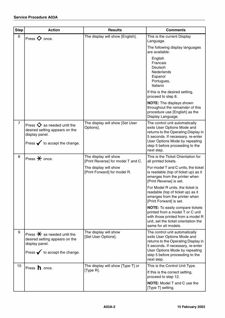
Service Procedure A03A
6Press once.
The display will show [English]. This is the current Display Language.
The following display languages are available:
EnglishFrancaisDeutschNederlandsEspanolPortugues,Italiano
If this is the desired setting, proceed to step 8.
NOTE: The displays shown throughout the remainder of this procedure use [English] as the Display Language.
7Press as needed until the desired setting appears on the display panel.
Press to accept the change.
The display will show [Set User Options].
The control unit automatically exits User Options Mode and returns to the Operating Display in 5 seconds. If necessary, re-enter User Options Mode by repeating step 5 before proceeding to the next step.
8Press once.
The display will show [Print Reverse] for model T and C.
The display will show [Print Forward] for model R.
This is the Ticket Orientation for all printed tickets.
For model T and C units, the ticket is readable (top of ticket up) as it emerges from the printer when [Print Reverse] is set.
For Model R units, the ticket is readable (top of ticket up) as it emerges from the printer when [Print Forward] is set.
NOTE: To easily compare tickets printed from a model T or C unit with those printed from a model R unit, set the ticket orientation the same for all models.
9Press as needed until the desired setting appears on the display panel.
Press to accept the change.
The display will show [Set User Options].
The control unit automatically exits User Options Mode and returns to the Operating Display in 5 seconds. If necessary, re-enter User Options Mode by repeating step 5 before proceeding to the next step.
10Press once.
The display will show [Type T] or [Type R].
This is the Control Unit Type.
If this is the correct setting, proceed to step 12.
NOTE: Model T and C use the [Type T] setting.
Step Action Results Comments
A03A-2 15 February 2003
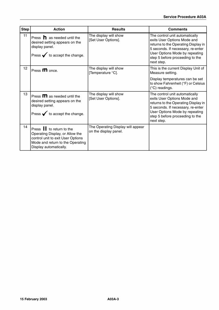
Service Procedure A03A
11Press as needed until the desired setting appears on the display panel.
Press to accept the change.
The display will show [Set User Options].
The control unit automatically exits User Options Mode and returns to the Operating Display in 5 seconds. If necessary, re-enter User Options Mode by repeating step 5 before proceeding to the next step.
12Press once.
The display will show [Temperature °C].
This is the current Display Unit of Measure setting.
Display temperatures can be set to show Fahrenheit (°F) or Celsius (°C) readings.
13Press as needed until the desired setting appears on the display panel.
Press to accept the change.
The display will show [Set User Options].
The control unit automatically exits User Options Mode and returns to the Operating Display in 5 seconds. If necessary, re-enter User Options Mode by repeating step 5 before proceeding to the next step.
14Press to return to the Operating Display, or Allow the control unit to exit User Options Mode and return to the Operating Display automatically.
The Operating Display will appear on the display panel.
Step Action Results Comments
A03A-315 February 2003

Service Procedure A03A
A03A-4 15 February 2003
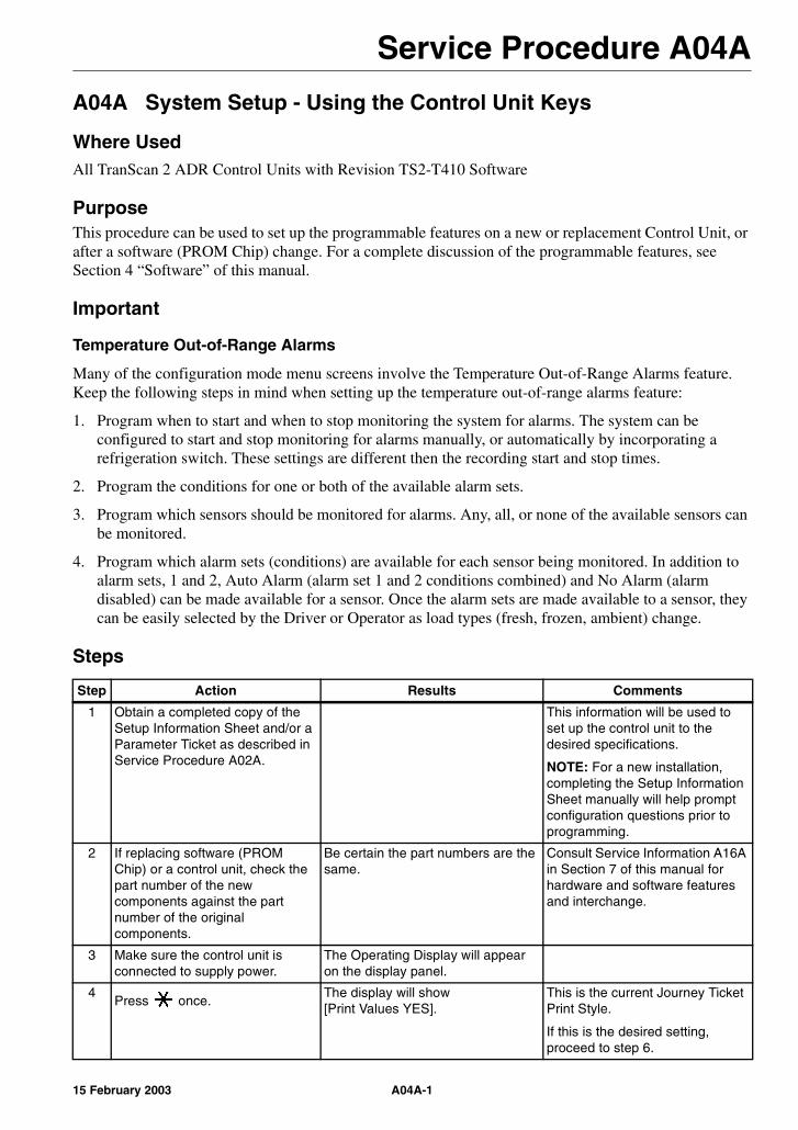
Service Procedure A04A
A04A System Setup - Using the Control Unit Keys
Where UsedAll TranScan 2 ADR Control Units with Revision TS2-T410 Software
PurposeThis procedure can be used to set up the programmable features on a new or replacement Control Unit, or after a software (PROM Chip) change. For a complete discussion of the programmable features, see Section 4 “Software” of this manual.
Important
Temperature Out-of-Range Alarms
Many of the configuration mode menu screens involve the Temperature Out-of-Range Alarms feature. Keep the following steps in mind when setting up the temperature out-of-range alarms feature:
1. Program when to start and when to stop monitoring the system for alarms. The system can be configured to start and stop monitoring for alarms manually, or automatically by incorporating a refrigeration switch. These settings are different then the recording start and stop times.
2. Program the conditions for one or both of the available alarm sets.
3. Program which sensors should be monitored for alarms. Any, all, or none of the available sensors can be monitored.
4. Program which alarm sets (conditions) are available for each sensor being monitored. In addition to alarm sets, 1 and 2, Auto Alarm (alarm set 1 and 2 conditions combined) and No Alarm (alarm disabled) can be made available for a sensor. Once the alarm sets are made available to a sensor, they can be easily selected by the Driver or Operator as load types (fresh, frozen, ambient) change.
Steps
Step Action Results Comments
1 Obtain a completed copy of the Setup Information Sheet and/or a Parameter Ticket as described in Service Procedure A02A.
This information will be used to set up the control unit to the desired specifications.
NOTE: For a new installation, completing the Setup Information Sheet manually will help prompt configuration questions prior to programming.
2 If replacing software (PROM Chip) or a control unit, check the part number of the new components against the part number of the original components.
Be certain the part numbers are the same.
Consult Service Information A16A in Section 7 of this manual for hardware and software features and interchange.
3 Make sure the control unit is connected to supply power.
The Operating Display will appear on the display panel.
4Press once.
The display will show [Print Values YES].
This is the current Journey Ticket Print Style.
If this is the desired setting, proceed to step 6.
A04A-115 February 2003
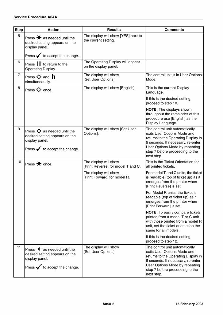
Service Procedure A04A
5Press as needed until the desired setting appears on the display panel.
Press to accept the change.
The display will show [YES] next to the current setting.
6Press to return to the Operating Display.
The Operating Display will appear on the display panel.
7Press and simultaneously.
The display will show [Set User Options].
The control unit is in User Options Mode.
8Press once.
The display will show [English]. This is the current Display Language.
If this is the desired setting, proceed to step 10.
NOTE: The displays shown throughout the remainder of this procedure use [English] as the Display Language.
9Press as needed until the desired setting appears on the display panel.
Press to accept the change.
The display will show [Set User Options].
The control unit automatically exits User Options Mode and returns to the Operating Display in 5 seconds. If necessary, re-enter User Options Mode by repeating step 7 before proceeding to the next step.
10Press once.
The display will show [Print Reverse] for model T and C.
The display will show [Print Forward] for model R.
This is the Ticket Orientation for all printed tickets.
For model T and C units, the ticket is readable (top of ticket up) as it emerges from the printer when [Print Reverse] is set.
For Model R units, the ticket is readable (top of ticket up) as it emerges from the printer when [Print Forward] is set.
NOTE: To easily compare tickets printed from a model T or C unit with those printed from a model R unit, set the ticket orientation the same for all models.
If this is the desired setting, proceed to step 12.
11Press as needed until the desired setting appears on the display panel.
Press to accept the change.
The display will show [Set User Options].
The control unit automatically exits User Options Mode and returns to the Operating Display in 5 seconds. If necessary, re-enter User Options Mode by repeating step 7 before proceeding to the next step.
Step Action Results Comments
A04A-2 15 February 2003

Service Procedure A04A
12Press once.
The display will show [Type T] or [Type R].
This is the Control Unit Type.
If this is the correct setting, proceed to step 14.
NOTE: Model T and C use the [Type T] setting.
13Press as needed until the desired setting appears on the display panel.
Press to accept the change.
The display will show [Set User Options].
The control unit automatically exits User Options Mode and returns to the Operating Display in 5 seconds. If necessary, re-enter User Options Mode by repeating step 7 before proceeding to the next step.
14Press once.
The display will show [Temperature °C].
This is the current Display Unit of Measure setting.
If this is the correct setting, proceed to step 16.
15Press as needed until the desired setting appears on the display panel.
Press to accept the change.
The display will show [Set User Options].
The control unit automatically exits User Options Mode and returns to the Operating Display in 5 seconds. If necessary, re-enter User Options Mode by repeating step 7 before proceeding to the next step.
16Press to return to the Operating Display, or Allow the control unit to exit User Options Mode and return to the Operating Display automatically.
The Operating Display will appear on the display panel.
17Press and simultaneously
The display will show [Enter PIN code].
18Press , , , to enter the default PIN code 1111.
The display will show [Start time 00:00]
This is the Set Recording Start Time screen. The control unit is now in Configuration Mode.
If this is the correct setting, proceed to step 20.
19Press or as needed to position the cursor.
Press or as needed until the desired setting appears on the display panel.
The display will show any changes to this setting.
20Press to accept changes(if any) and advance to the next screen.
The display will show [Stop time 00:00]
This is the Set Recording Stop Time screen.
If this is the correct setting, proceed to step 22.
Step Action Results Comments
A04A-315 February 2003
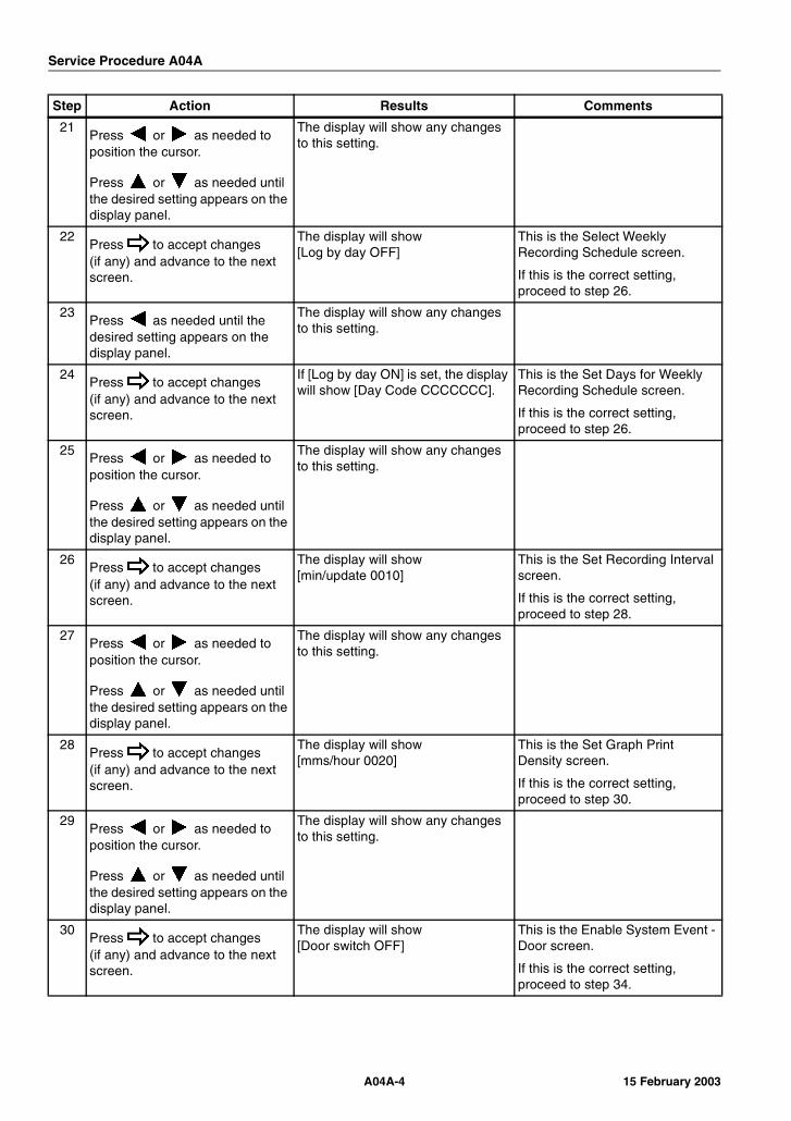
Service Procedure A04A
21Press or as needed to position the cursor.
Press or as needed until the desired setting appears on the display panel.
The display will show any changes to this setting.
22Press to accept changes(if any) and advance to the next screen.
The display will show [Log by day OFF]
This is the Select Weekly Recording Schedule screen.
If this is the correct setting, proceed to step 26.
23Press as needed until the desired setting appears on the display panel.
The display will show any changes to this setting.
24Press to accept changes(if any) and advance to the next screen.
If [Log by day ON] is set, the display will show [Day Code CCCCCCC].
This is the Set Days for Weekly Recording Schedule screen.
If this is the correct setting, proceed to step 26.
25Press or as needed to position the cursor.
Press or as needed until the desired setting appears on the display panel.
The display will show any changes to this setting.
26Press to accept changes(if any) and advance to the next screen.
The display will show [min/update 0010]
This is the Set Recording Interval screen.
If this is the correct setting, proceed to step 28.
27Press or as needed to position the cursor.
Press or as needed until the desired setting appears on the display panel.
The display will show any changes to this setting.
28Press to accept changes(if any) and advance to the next screen.
The display will show [mms/hour 0020]
This is the Set Graph Print Density screen.
If this is the correct setting, proceed to step 30.
29Press or as needed to position the cursor.
Press or as needed until the desired setting appears on the display panel.
The display will show any changes to this setting.
30Press to accept changes(if any) and advance to the next screen.
The display will show [Door switch OFF]
This is the Enable System Event - Door screen.
If this is the correct setting, proceed to step 34.
Step Action Results Comments
A04A-4 15 February 2003
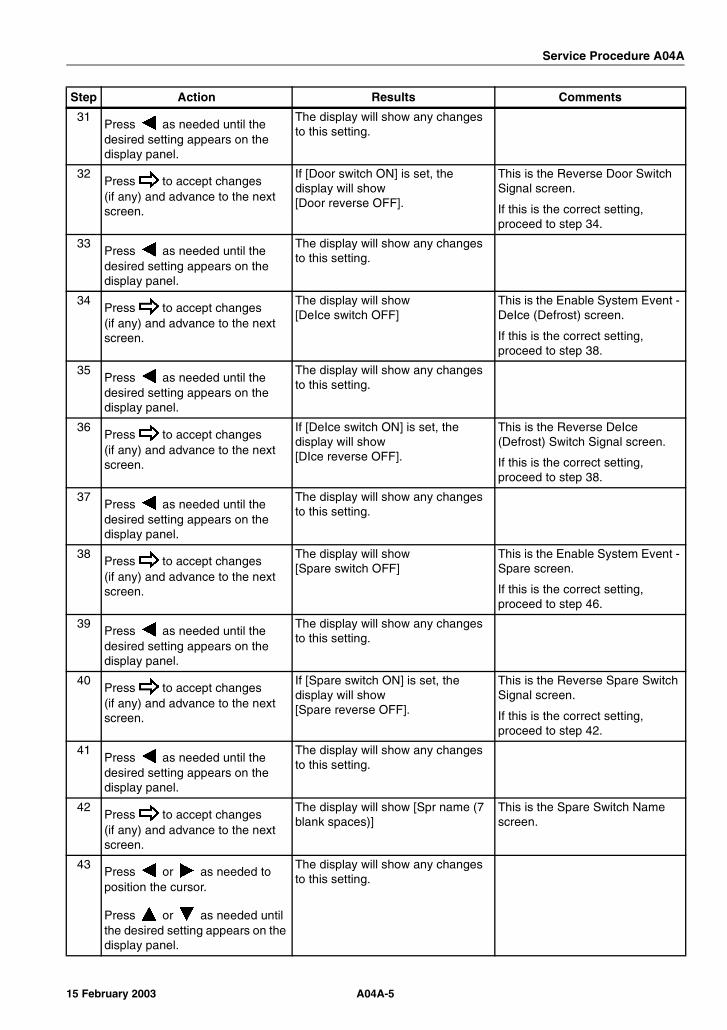
Service Procedure A04A
31Press as needed until the desired setting appears on the display panel.
The display will show any changes to this setting.
32Press to accept changes(if any) and advance to the next screen.
If [Door switch ON] is set, the display will show [Door reverse OFF].
This is the Reverse Door Switch Signal screen.
If this is the correct setting, proceed to step 34.
33Press as needed until the desired setting appears on the display panel.
The display will show any changes to this setting.
34Press to accept changes(if any) and advance to the next screen.
The display will show [DeIce switch OFF]
This is the Enable System Event - DeIce (Defrost) screen.
If this is the correct setting, proceed to step 38.
35Press as needed until the desired setting appears on the display panel.
The display will show any changes to this setting.
36Press to accept changes(if any) and advance to the next screen.
If [DeIce switch ON] is set, the display will show [DIce reverse OFF].
This is the Reverse DeIce (Defrost) Switch Signal screen.
If this is the correct setting, proceed to step 38.
37Press as needed until the desired setting appears on the display panel.
The display will show any changes to this setting.
38Press to accept changes(if any) and advance to the next screen.
The display will show [Spare switch OFF]
This is the Enable System Event - Spare screen.
If this is the correct setting, proceed to step 46.
39Press as needed until the desired setting appears on the display panel.
The display will show any changes to this setting.
40Press to accept changes(if any) and advance to the next screen.
If [Spare switch ON] is set, the display will show [Spare reverse OFF].
This is the Reverse Spare Switch Signal screen.
If this is the correct setting, proceed to step 42.
41Press as needed until the desired setting appears on the display panel.
The display will show any changes to this setting.
42Press to accept changes(if any) and advance to the next screen.
The display will show [Spr name (7 blank spaces)]
This is the Spare Switch Name screen.
43Press or as needed to position the cursor.
Press or as needed until the desired setting appears on the display panel.
The display will show any changes to this setting.
Step Action Results Comments
A04A-515 February 2003

Service Procedure A04A
44Press to accept changes(if any) and advance to the next screen.
The display will show [Spr symbol (1 blank space)].
This is the Spare Switch Event Indicator Symbol screen.
NOTE: the blank space = the rectangle door symbol in this screen only.
If this is the correct setting, proceed to step 46.
45Press or as needed until the desired setting appears on the display panel.
The display will show any changes to this setting.
46Press to accept changes(if any) and advance to the next screen.
The display will show [Alarm enable OFF].
This is the Enable Temperature Out-of-Range Alarm screen.
If this is the correct setting, proceed to step 54.
47Press as needed until the desired setting appears on the display panel.
The display will show any changes to this setting.
48Press to accept changes(if any) and advance to the next screen.
If [Alarm enable ON] is set, the display will show [Alarm reverse OFF].
This is the Reverse Refrigeration Switch Signal screen.
If this is the correct setting, proceed to step 50.
49Press as needed until the desired setting appears on the display panel.
The display will show any changes to this setting.
50Press to accept changes(if any) and advance to the next screen.
The display will show [Extend time OFF].
This is the Enable Extended Alarm Monitoring screen.
If this is the correct setting, proceed to step 52.
51Press as needed until the desired setting appears on the display panel.
The display will show any changes to this setting.
52Press to accept changes(if any) and advance to the next screen.
The display will show [Added time 00:45].
This is the Extended Alarm Monitoring Period screen.
If this is the correct setting, proceed to step 54.
53Press or as needed to position the cursor.
Press or as needed until the desired setting appears on the display panel.
The display will show any changes to this setting.
54Press to accept changes(if any) and advance to the next screen.
The display will show [Graph high 0010].
This is the Graph High Limit (alarms disabled) screen.
If this is the correct setting, proceed to step 56.
Step Action Results Comments
A04A-6 15 February 2003
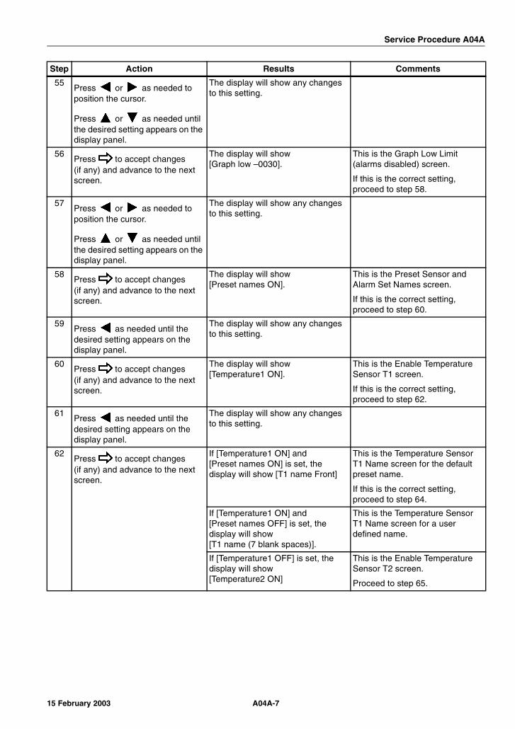
Service Procedure A04A
55Press or as needed to position the cursor.
Press or as needed until the desired setting appears on the display panel.
The display will show any changes to this setting.
56Press to accept changes(if any) and advance to the next screen.
The display will show[Graph low –0030].
This is the Graph Low Limit (alarms disabled) screen.
If this is the correct setting, proceed to step 58.
57Press or as needed to position the cursor.
Press or as needed until the desired setting appears on the display panel.
The display will show any changes to this setting.
58Press to accept changes(if any) and advance to the next screen.
The display will show [Preset names ON].
This is the Preset Sensor and Alarm Set Names screen.
If this is the correct setting, proceed to step 60.
59Press as needed until the desired setting appears on the display panel.
The display will show any changes to this setting.
60Press to accept changes(if any) and advance to the next screen.
The display will show [Temperature1 ON].
This is the Enable Temperature Sensor T1 screen.
If this is the correct setting, proceed to step 62.
61Press as needed until the desired setting appears on the display panel.
The display will show any changes to this setting.
62Press to accept changes(if any) and advance to the next screen.
If [Temperature1 ON] and [Preset names ON] is set, the display will show [T1 name Front]
This is the Temperature Sensor T1 Name screen for the default preset name.
If this is the correct setting, proceed to step 64.
If [Temperature1 ON] and [Preset names OFF] is set, the display will show [T1 name (7 blank spaces)].
This is the Temperature Sensor T1 Name screen for a user defined name.
If [Temperature1 OFF] is set, the display will show [Temperature2 ON]
This is the Enable Temperature Sensor T2 screen.
Proceed to step 65.
Step Action Results Comments
A04A-715 February 2003

Service Procedure A04A
63 Preset Names:
Press as needed until the desired setting appears on the display panel.
The display will show any changes to this setting.
User Defined Names:
Press or as needed to position the cursor.
Press or as needed until the desired setting appears on the display panel.
64Press to accept changes(if any) and advance to the next screen.
The display will show [Temperature2 ON].
This is the Enable Temperature Sensor T2 screen.
If this is the correct setting, proceed to step 66.
65Press as needed until the desired setting appears on the display panel.
The display will show any changes to this setting.
66Press to accept changes(if any) and advance to the next screen.
If [Temperature2 ON] and [Preset names ON] is set, the display will show [T2 name Rear]
This is the Temperature Sensor T2 Name screen with the default preset name.
If this is the correct setting, proceed to step 68.
If [Temperature2 ON] and [Preset names OFF] is set, the display will show [T2 name (7 blank spaces)].
This is the Temperature Sensor T2 Name screen for a user defined name.
If [Temperature2 OFF] is set, the display will show [Temperature3 OFF]
This is the Enable Temperature Sensor T3 screen.
Proceed to step 69.
67 Preset Names:
Press , or as needed until the desired setting appears on the display panel.
The display will show any changes to this setting.
User Defined Names:
Press or as needed to position the cursor.
Press or as needed until the desired setting appears on the display panel.
68Press to accept changes(if any) and advance to the next screen.
The display will show [Temperature3 OFF].
This is the Enable Temperature Sensor T3 screen.
If this is the correct setting, proceed to step 70.
69Press as needed until the desired setting appears on the display panel.
The display will show any changes to this setting.
Step Action Results Comments
A04A-8 15 February 2003

Service Procedure A04A
70Press to accept changes(if any) and advance to the next screen.
If [Temperature3 OFF] is set, the display will show [Temperature4 OFF]
This is the Enable Temperature Sensor T4 screen.
Proceed to step 73.
If [Temperature3 ON] and [Preset names ON] is set, the display will show [T3 name Air Ret]
This is the Temperature Sensor T3 Name screen with the default preset name.
If this is the correct setting, proceed to step 72.
If [Temperature3 ON] and [Preset names OFF] is set, the display will show [T3 name (7 blank spaces)].
This is the Temperature Sensor T3 Name screen for a user defined name.
71 Preset Names:
Press , or as needed until the desired setting appears on the display panel.
The display will show any changes to this setting.
User Defined Names:
Press or as needed to position the cursor.
Press or as needed until the desired setting appears on the display panel.
72Press to accept changes(if any) and advance to the next screen.
The display will show [Temperature4 OFF].
This is the Enable Temperature Sensor T4 screen.
If this is the correct setting, proceed to step 74.
73Press as needed until the desired setting appears on the display panel.
The display will show any changes to this setting.
74Press to accept changes(if any) and advance to the next screen.
If [Temperature4 OFF] is set, the display will show [Alarm set 1 ON].
This is the Enable Alarm Set 1 screen.
Proceed to step 77.
If [Temperature4 ON] and [Preset names ON] is set, the display will show [T4 name Product]
This is the Temperature Sensor T4 Name screen with the default preset name.
If this is the correct setting, proceed to step 76.
If [Temperature4 ON] and [Preset names OFF] is set, the display will show [T4 name (7 blank spaces)].
This is the Temperature Sensor T4 Name screen for a user defined name.
Step Action Results Comments
A04A-915 February 2003
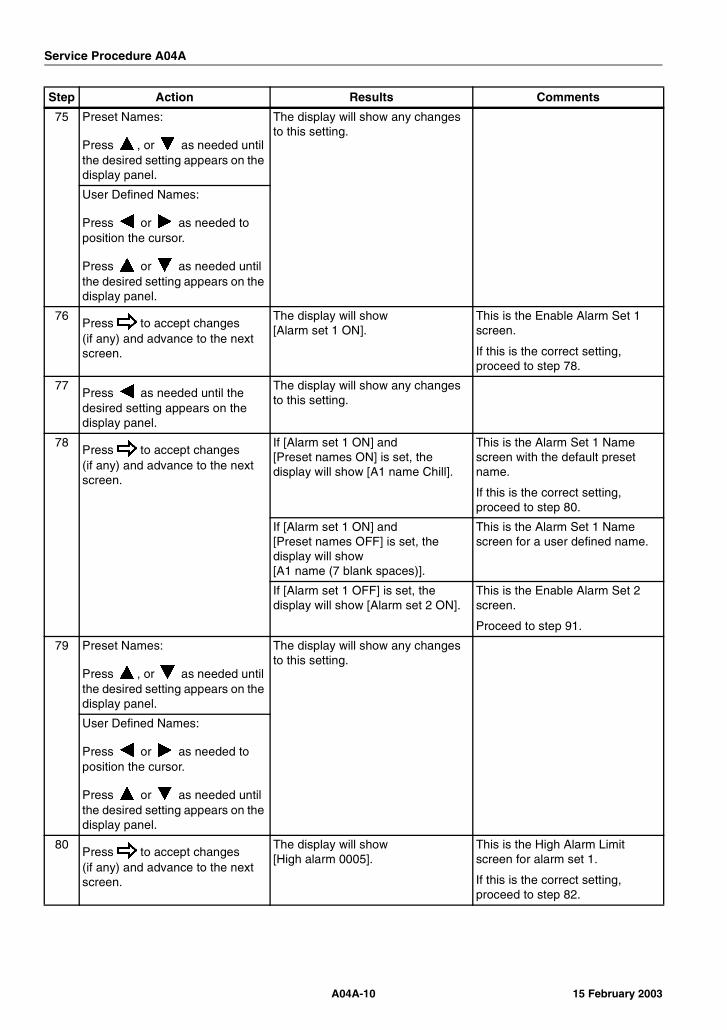
Service Procedure A04A
75 Preset Names:
Press , or as needed until the desired setting appears on the display panel.
The display will show any changes to this setting.
User Defined Names:
Press or as needed to position the cursor.
Press or as needed until the desired setting appears on the display panel.
76Press to accept changes(if any) and advance to the next screen.
The display will show [Alarm set 1 ON].
This is the Enable Alarm Set 1 screen.
If this is the correct setting, proceed to step 78.
77Press as needed until the desired setting appears on the display panel.
The display will show any changes to this setting.
78Press to accept changes(if any) and advance to the next screen.
If [Alarm set 1 ON] and [Preset names ON] is set, the display will show [A1 name Chill].
This is the Alarm Set 1 Name screen with the default preset name.
If this is the correct setting, proceed to step 80.
If [Alarm set 1 ON] and [Preset names OFF] is set, the display will show [A1 name (7 blank spaces)].
This is the Alarm Set 1 Name screen for a user defined name.
If [Alarm set 1 OFF] is set, the display will show [Alarm set 2 ON].
This is the Enable Alarm Set 2 screen.
Proceed to step 91.
79 Preset Names:
Press , or as needed until the desired setting appears on the display panel.
The display will show any changes to this setting.
User Defined Names:
Press or as needed to position the cursor.
Press or as needed until the desired setting appears on the display panel.
80Press to accept changes(if any) and advance to the next screen.
The display will show [High alarm 0005].
This is the High Alarm Limit screen for alarm set 1.
If this is the correct setting, proceed to step 82.
Step Action Results Comments
A04A-10 15 February 2003

Service Procedure A04A
81Press or as needed to position the cursor.
Press or as needed until the desired setting appears on the display panel.
The display will show any changes to this setting.
82Press to accept changes(if any) and advance to the next screen.
The display will show [Low alarm 0001].
This is the Low Alarm Limit screen for alarm set 1.
If this is the correct setting, proceed to step 84.
83Press or as needed to position the cursor.
Press or as needed until the desired setting appears on the display panel.
The display will show any changes to this setting.
84Press to accept changes(if any) and advance to the next screen.
The display will show [Alarm wait 0030].
This is the Alarm Delay Period screen for alarm set 1.
If this is the correct setting, proceed to step 86.
85Press or as needed to position the cursor.
Press or as needed until the desired setting appears on the display panel.
The display will show any changes to this setting.
86Press to accept changes(if any) and advance to the next screen.
The display will show [Graph high 0010].
This is the Graph Print High Limit screen for alarm set 1.
If this is the correct setting, proceed to step 88.
87Press or as needed to position the cursor.
Press or as needed until the desired setting appears on the display panel.
The display will show any changes to this setting.
88Press to accept changes(if any) and advance to the next screen.
The display will show[Graph low –0010].
This is the Graph Print Low Limit screen for alarm set 1.
If this is the correct setting, proceed to step 90.
89Press or as needed to position the cursor.
Press or as needed until the desired setting appears on the display panel.
The display will show any changes to this setting.
90Press to accept changes(if any) and advance to the next screen.
The display will show [Alarm set 2 ON].
This is the Enable Alarm Set 2 screen.
If this is the correct setting, proceed to step 92.
Step Action Results Comments
A04A-1115 February 2003
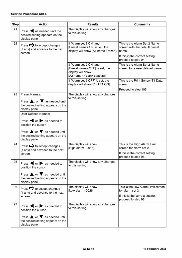
Service Procedure A04A
91Press as needed until the desired setting appears on the display panel.
The display will show any changes to this setting.
92Press to accept changes(if any) and advance to the next screen.
If [Alarm set 2 ON] and [Preset names ON] is set, the display will show [A1 name Frozen].
This is the Alarm Set 2 Name screen with the default preset name.
If this is the correct setting, proceed to step 94.
If [Alarm set 2 ON] and [Preset names OFF] is set, the display will show [A2 name (7 blank spaces)].
This is the Alarm Set 2 Name screen for a user defined name.
If [Alarm set 2 OFF] is set, the display will show [Print T1 ON].
This is the Print Sensor T1 Data screen.
Proceed to step 105.
93 Preset Names:
Press , or as needed until the desired setting appears on the display panel.
The display will show any changes to this setting.
User Defined Names:
Press or as needed to position the cursor.
Press or as needed until the desired setting appears on the display panel.
94Press to accept changes(if any) and advance to the next screen.
The display will show[High alarm –0015].
This is the High Alarm Limit screen for alarm set 2.
If this is the correct setting, proceed to step 96.
95Press or as needed to position the cursor.
Press or as needed until the desired setting appears on the display panel.
The display will show any changes to this setting.
96Press to accept changes(if any) and advance to the next screen.
The display will show[Low alarm –0025].
This is the Low Alarm Limit screen for alarm set 2.
If this is the correct setting, proceed to step 98.
97Press or as needed to position the cursor.
Press or as needed until the desired setting appears on the display panel.
The display will show any changes to this setting.
Step Action Results Comments
A04A-12 15 February 2003
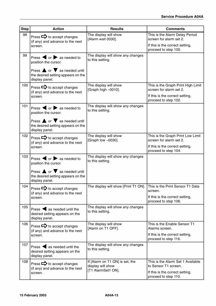
Service Procedure A04A
98Press to accept changes(if any) and advance to the next screen.
The display will show [Alarm wait 0030].
This is the Alarm Delay Period screen for alarm set 2.
If this is the correct setting, proceed to step 100.
99Press or as needed to position the cursor.
Press or as needed until the desired setting appears on the display panel.
The display will show any changes to this setting.
100Press to accept changes(if any) and advance to the next screen.
The display will show[Graph high –0010].
This is the Graph Print High Limit screen for alarm set 2.
If this is the correct setting, proceed to step 102.
101Press or as needed to position the cursor.
Press or as needed until the desired setting appears on the display panel.
The display will show any changes to this setting.
102Press to accept changes(if any) and advance to the next screen.
The display will show[Graph low –0030].
This is the Graph Print Low Limit screen for alarm set 2.
If this is the correct setting, proceed to step 104.
103Press or as needed to position the cursor.
Press or as needed until the desired setting appears on the display panel.
The display will show any changes to this setting.
104Press to accept changes(if any) and advance to the next screen.
The display will show [Print T1 ON]. This is the Print Sensor T1 Data screen.
If this is the correct setting, proceed to step 106.
105Press as needed until the desired setting appears on the display panel.
The display will show any changes to this setting.
106Press to accept changes(if any) and advance to the next screen.
The display will show [Alarm on T1 OFF].
This is the Enable Sensor T1 Alarms screen.
If this is the correct setting, proceed to step 116.
107Press as needed until the desired setting appears on the display panel.
The display will show any changes to this setting.
108Press to accept changes(if any) and advance to the next screen.
If [Alarm on T1 ON] is set, the display will show [T1 AlarmSet1 ON].
This is the Alarm Set 1 Available to Sensor T1 screen.
If this is the correct setting, proceed to step 110.
Step Action Results Comments
A04A-1315 February 2003
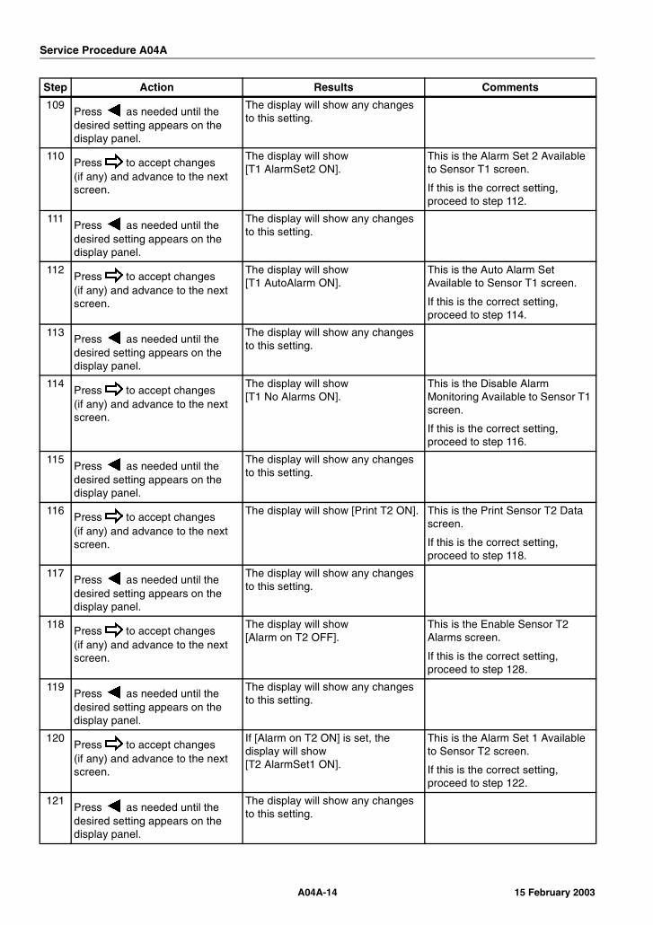
Service Procedure A04A
109Press as needed until the desired setting appears on the display panel.
The display will show any changes to this setting.
110Press to accept changes(if any) and advance to the next screen.
The display will show [T1 AlarmSet2 ON].
This is the Alarm Set 2 Available to Sensor T1 screen.
If this is the correct setting, proceed to step 112.
111Press as needed until the desired setting appears on the display panel.
The display will show any changes to this setting.
112Press to accept changes(if any) and advance to the next screen.
The display will show [T1 AutoAlarm ON].
This is the Auto Alarm Set Available to Sensor T1 screen.
If this is the correct setting, proceed to step 114.
113Press as needed until the desired setting appears on the display panel.
The display will show any changes to this setting.
114Press to accept changes(if any) and advance to the next screen.
The display will show [T1 No Alarms ON].
This is the Disable Alarm Monitoring Available to Sensor T1 screen.
If this is the correct setting, proceed to step 116.
115Press as needed until the desired setting appears on the display panel.
The display will show any changes to this setting.
116Press to accept changes(if any) and advance to the next screen.
The display will show [Print T2 ON]. This is the Print Sensor T2 Data screen.
If this is the correct setting, proceed to step 118.
117Press as needed until the desired setting appears on the display panel.
The display will show any changes to this setting.
118Press to accept changes(if any) and advance to the next screen.
The display will show [Alarm on T2 OFF].
This is the Enable Sensor T2 Alarms screen.
If this is the correct setting, proceed to step 128.
119Press as needed until the desired setting appears on the display panel.
The display will show any changes to this setting.
120Press to accept changes(if any) and advance to the next screen.
If [Alarm on T2 ON] is set, the display will show [T2 AlarmSet1 ON].
This is the Alarm Set 1 Available to Sensor T2 screen.
If this is the correct setting, proceed to step 122.
121Press as needed until the desired setting appears on the display panel.
The display will show any changes to this setting.
Step Action Results Comments
A04A-14 15 February 2003
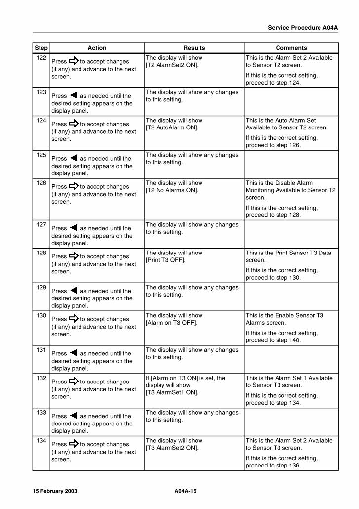
Service Procedure A04A
122Press to accept changes(if any) and advance to the next screen.
The display will show [T2 AlarmSet2 ON].
This is the Alarm Set 2 Available to Sensor T2 screen.
If this is the correct setting, proceed to step 124.
123Press as needed until the desired setting appears on the display panel.
The display will show any changes to this setting.
124Press to accept changes(if any) and advance to the next screen.
The display will show [T2 AutoAlarm ON].
This is the Auto Alarm Set Available to Sensor T2 screen.
If this is the correct setting, proceed to step 126.
125Press as needed until the desired setting appears on the display panel.
The display will show any changes to this setting.
126Press to accept changes(if any) and advance to the next screen.
The display will show [T2 No Alarms ON].
This is the Disable Alarm Monitoring Available to Sensor T2 screen.
If this is the correct setting, proceed to step 128.
127Press as needed until the desired setting appears on the display panel.
The display will show any changes to this setting.
128Press to accept changes(if any) and advance to the next screen.
The display will show [Print T3 OFF].
This is the Print Sensor T3 Data screen.
If this is the correct setting, proceed to step 130.
129Press as needed until the desired setting appears on the display panel.
The display will show any changes to this setting.
130Press to accept changes(if any) and advance to the next screen.
The display will show [Alarm on T3 OFF].
This is the Enable Sensor T3 Alarms screen.
If this is the correct setting, proceed to step 140.
131Press as needed until the desired setting appears on the display panel.
The display will show any changes to this setting.
132Press to accept changes(if any) and advance to the next screen.
If [Alarm on T3 ON] is set, the display will show [T3 AlarmSet1 ON].
This is the Alarm Set 1 Available to Sensor T3 screen.
If this is the correct setting, proceed to step 134.
133Press as needed until the desired setting appears on the display panel.
The display will show any changes to this setting.
134Press to accept changes(if any) and advance to the next screen.
The display will show [T3 AlarmSet2 ON].
This is the Alarm Set 2 Available to Sensor T3 screen.
If this is the correct setting, proceed to step 136.
Step Action Results Comments
A04A-1515 February 2003
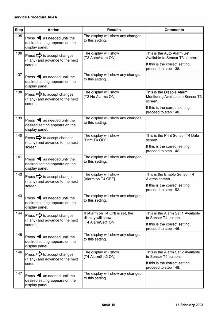
Service Procedure A04A
135Press as needed until the desired setting appears on the display panel.
The display will show any changes to this setting.
136Press to accept changes(if any) and advance to the next screen.
The display will show [T3 AutoAlarm ON].
This is the Auto Alarm Set Available to Sensor T3 screen.
If this is the correct setting, proceed to step 138.
137Press as needed until the desired setting appears on the display panel.
The display will show any changes to this setting.
138Press to accept changes(if any) and advance to the next screen.
The display will show [T3 No Alarms ON].
This is the Disable Alarm Monitoring Available to Sensor T3 screen.
If this is the correct setting, proceed to step 140.
139Press as needed until the desired setting appears on the display panel.
The display will show any changes to this setting.
140Press to accept changes(if any) and advance to the next screen.
The display will show [Print T4 OFF].
This is the Print Sensor T4 Data screen.
If this is the correct setting, proceed to step 142.
141Press as needed until the desired setting appears on the display panel.
The display will show any changes to this setting.
142Press to accept changes(if any) and advance to the next screen.
The display will show [Alarm on T4 OFF].
This is the Enable Sensor T4 Alarms screen.
If this is the correct setting, proceed to step 152.
143Press as needed until the desired setting appears on the display panel.
The display will show any changes to this setting.
144Press to accept changes(if any) and advance to the next screen.
If [Alarm on T4 ON] is set, the display will show [T4 AlarmSet1 ON].
This is the Alarm Set 1 Available to Sensor T4 screen.
If this is the correct setting, proceed to step 146.
145Press as needed until the desired setting appears on the display panel.
The display will show any changes to this setting.
146Press to accept changes(if any) and advance to the next screen.
The display will show [T4 AlarmSet2 ON].
This is the Alarm Set 2 Available to Sensor T4 screen.
If this is the correct setting, proceed to step 148.
147Press as needed until the desired setting appears on the display panel.
The display will show any changes to this setting.
Step Action Results Comments
A04A-16 15 February 2003
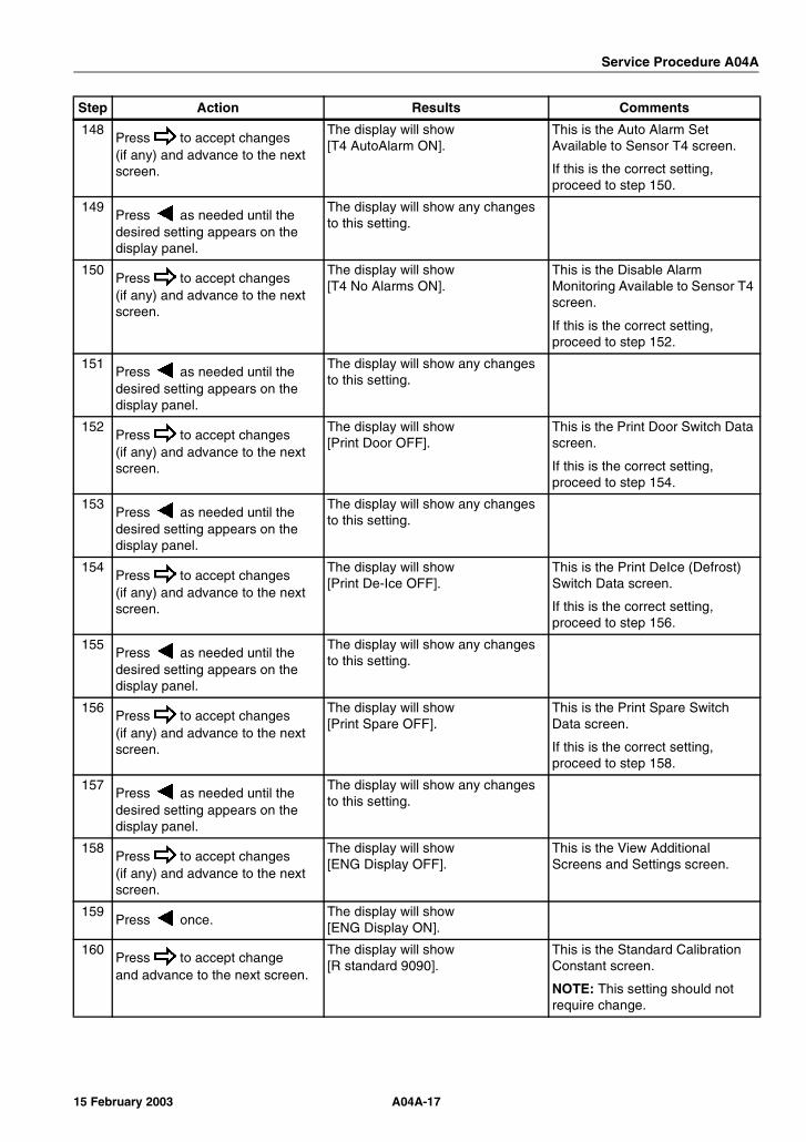
Service Procedure A04A
148Press to accept changes(if any) and advance to the next screen.
The display will show [T4 AutoAlarm ON].
This is the Auto Alarm Set Available to Sensor T4 screen.
If this is the correct setting, proceed to step 150.
149Press as needed until the desired setting appears on the display panel.
The display will show any changes to this setting.
150Press to accept changes(if any) and advance to the next screen.
The display will show [T4 No Alarms ON].
This is the Disable Alarm Monitoring Available to Sensor T4 screen.
If this is the correct setting, proceed to step 152.
151Press as needed until the desired setting appears on the display panel.
The display will show any changes to this setting.
152Press to accept changes(if any) and advance to the next screen.
The display will show [Print Door OFF].
This is the Print Door Switch Data screen.
If this is the correct setting, proceed to step 154.
153Press as needed until the desired setting appears on the display panel.
The display will show any changes to this setting.
154Press to accept changes(if any) and advance to the next screen.
The display will show [Print De-Ice OFF].
This is the Print DeIce (Defrost) Switch Data screen.
If this is the correct setting, proceed to step 156.
155Press as needed until the desired setting appears on the display panel.
The display will show any changes to this setting.
156Press to accept changes(if any) and advance to the next screen.
The display will show [Print Spare OFF].
This is the Print Spare Switch Data screen.
If this is the correct setting, proceed to step 158.
157Press as needed until the desired setting appears on the display panel.
The display will show any changes to this setting.
158Press to accept changes(if any) and advance to the next screen.
The display will show [ENG Display OFF].
This is the View Additional Screens and Settings screen.
159Press once.
The display will show [ENG Display ON].
160Press to accept changeand advance to the next screen.
The display will show [R standard 9090].
This is the Standard Calibration Constant screen.
NOTE: This setting should not require change.
Step Action Results Comments
A04A-1715 February 2003
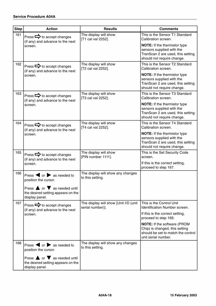
Service Procedure A04A
161Press to accept changes(if any) and advance to the next screen.
The display will show [T1 cal val 2252].
This is the Sensor T1 Standard Calibration screen.
NOTE: If the thermistor type sensors supplied with the TranScan 2 are used, this setting should not require change.
162Press to accept changes(if any) and advance to the next screen.
The display will show [T2 cal val 2252].
This is the Sensor T2 Standard Calibration screen.
NOTE: If the thermistor type sensors supplied with the TranScan 2 are used, this setting should not require change.
163Press to accept changes(if any) and advance to the next screen.
The display will show [T3 cal val 2252].
This is the Sensor T3 Standard Calibration screen.
NOTE: If the thermistor type sensors supplied with the TranScan 2 are used, this setting should not require change.
164Press to accept changes(if any) and advance to the next screen.
The display will show [T4 cal val 2252].
This is the Sensor T4 Standard Calibration screen.
NOTE: If the thermistor type sensors supplied with the TranScan 2 are used, this setting should not require change.
165Press to accept changes(if any) and advance to the next screen.
The display will show [PIN number 1111].
This is the Set Security Code screen.
If this is the correct setting, proceed to step 167.
166Press or as needed to position the cursor.
Press or as needed until the desired setting appears on the display panel.
The display will show any changes to this setting.
167Press to accept changes(if any) and advance to the next screen.
The display will show [Unit I/D (unit serial number)].
This is the Control Unit Identification Number screen.
If this is the correct setting, proceed to step 169.
NOTE: If the software (PROM Chip) is changed, this setting should be set to match the control unit serial number.
168Press or as needed to position the cursor.
Press or as needed until the desired setting appears on the display panel.
The display will show any changes to this setting.
Step Action Results Comments
A04A-18 15 February 2003
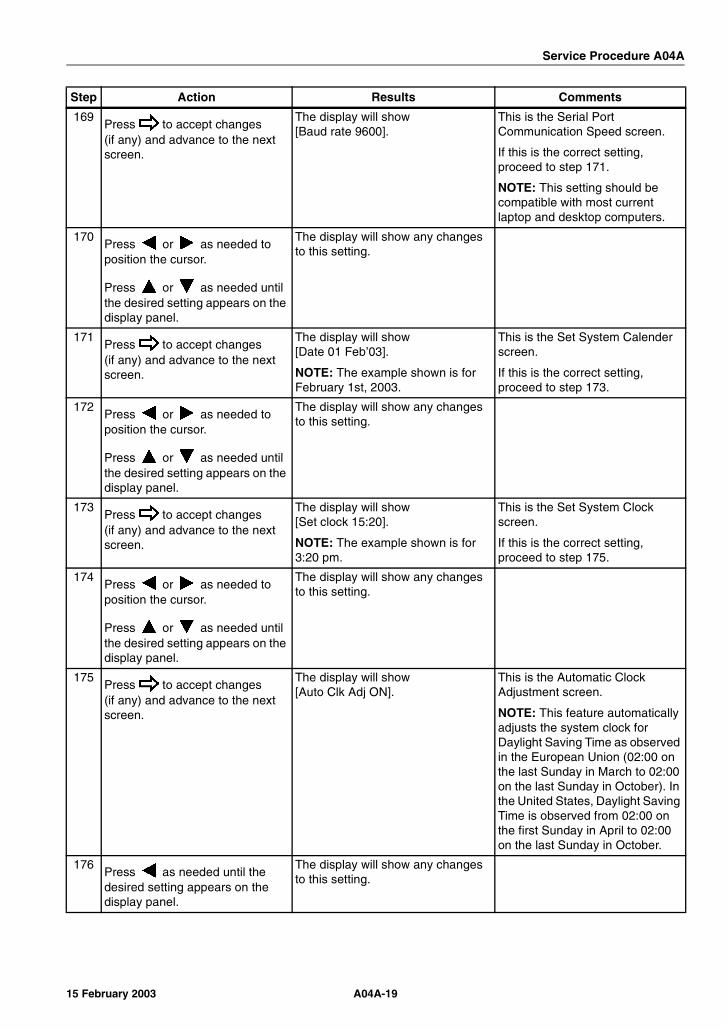
Service Procedure A04A
169Press to accept changes(if any) and advance to the next screen.
The display will show [Baud rate 9600].
This is the Serial Port Communication Speed screen.
If this is the correct setting, proceed to step 171.
NOTE: This setting should be compatible with most current laptop and desktop computers.
170Press or as needed to position the cursor.
Press or as needed until the desired setting appears on the display panel.
The display will show any changes to this setting.
171Press to accept changes(if any) and advance to the next screen.
The display will show [Date 01 Feb’03].
NOTE: The example shown is for February 1st, 2003.
This is the Set System Calender screen.
If this is the correct setting, proceed to step 173.
172Press or as needed to position the cursor.
Press or as needed until the desired setting appears on the display panel.
The display will show any changes to this setting.
173Press to accept changes(if any) and advance to the next screen.
The display will show [Set clock 15:20].
NOTE: The example shown is for 3:20 pm.
This is the Set System Clock screen.
If this is the correct setting, proceed to step 175.
174Press or as needed to position the cursor.
Press or as needed until the desired setting appears on the display panel.
The display will show any changes to this setting.
175Press to accept changes(if any) and advance to the next screen.
The display will show [Auto Clk Adj ON].
This is the Automatic Clock Adjustment screen.
NOTE: This feature automatically adjusts the system clock for Daylight Saving Time as observed in the European Union (02:00 on the last Sunday in March to 02:00 on the last Sunday in October). In the United States, Daylight Saving Time is observed from 02:00 on the first Sunday in April to 02:00 on the last Sunday in October.
176Press as needed until the desired setting appears on the display panel.
The display will show any changes to this setting.
Step Action Results Comments
A04A-1915 February 2003

Service Procedure A04A
177Press to accept changes(if any) and advance to the next screen.
The display will show [Clk Protect OFF].
This is the Clock Adjustment Protection screen.
If this is the correct setting, proceed to step 179.
178Press as needed until the desired setting appears on the display panel.
The display will show any changes to this setting.
179Press to accept changes(if any) and return to the previous screen.
Press 11 more times to return to the View Additional Screens and Settings screen.
The display will show [ENG Display ON].
180Press once.
The display will show [ENG Display OFF].
181Press to accept changeand advance to the next screen.
The display will show [Vehicle TRL 1234].
NOTE: The example shown is for a model T control unit.
This is the Vehicle Identification Number screen.
182Press or as needed to position the cursor.
Press or as needed until the desired setting appears on the display panel.
The display will show any changes to this setting.
183Press to accept changeand advance to the next screen.
The display will show [Title1 Company].
This is the Ticket Heading screen for the 1st 8 of 16 digits.
184Press or as needed to position the cursor.
Press or as needed until the desired setting appears on the display panel.
The display will show any changes to this setting.
185Press to accept changeand advance to the next screen.
The display will show [Title2 Name]. This is the Ticket Heading screen for the 2nd 8 of 16 digits.
186Press or as needed to position the cursor.
Press or as needed until the desired setting appears on the display panel.
The display will show any changes to this setting.
187Press to exit Configuration Mode.
The Operating Display will appear on the display panel.
The TranScan 2 ADR Control Unit should be ready to place into service.
Step Action Results Comments
A04A-20 15 February 2003
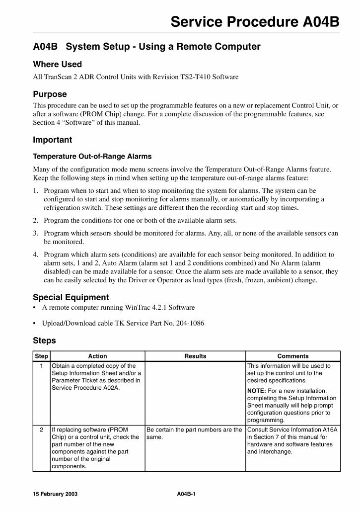
Service Procedure A04B
A04B System Setup - Using a Remote Computer
Where UsedAll TranScan 2 ADR Control Units with Revision TS2-T410 Software
PurposeThis procedure can be used to set up the programmable features on a new or replacement Control Unit, or after a software (PROM Chip) change. For a complete discussion of the programmable features, see Section 4 “Software” of this manual.
Important
Temperature Out-of-Range Alarms
Many of the configuration mode menu screens involve the Temperature Out-of-Range Alarms feature. Keep the following steps in mind when setting up the temperature out-of-range alarms feature:
1. Program when to start and when to stop monitoring the system for alarms. The system can be configured to start and stop monitoring for alarms manually, or automatically by incorporating a refrigeration switch. These settings are different then the recording start and stop times.
2. Program the conditions for one or both of the available alarm sets.
3. Program which sensors should be monitored for alarms. Any, all, or none of the available sensors can be monitored.
4. Program which alarm sets (conditions) are available for each sensor being monitored. In addition to alarm sets, 1 and 2, Auto Alarm (alarm set 1 and 2 conditions combined) and No Alarm (alarm disabled) can be made available for a sensor. Once the alarm sets are made available to a sensor, they can be easily selected by the Driver or Operator as load types (fresh, frozen, ambient) change.
Special Equipment• A remote computer running WinTrac 4.2.1 Software
• Upload/Download cable TK Service Part No. 204-1086
Steps
Step Action Results Comments
1 Obtain a completed copy of the Setup Information Sheet and/or a Parameter Ticket as described in Service Procedure A02A.
This information will be used to set up the control unit to the desired specifications.
NOTE: For a new installation, completing the Setup Information Sheet manually will help prompt configuration questions prior to programming.
2 If replacing software (PROM Chip) or a control unit, check the part number of the new components against the part number of the original components.
Be certain the part numbers are the same.
Consult Service Information A16A in Section 7 of this manual for hardware and software features and interchange.
A04B-115 February 2003
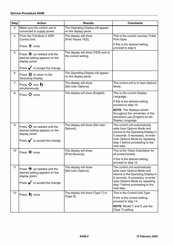
Service Procedure A04B
3 Make sure the control unit is connected to supply power.
The Operating Display will appear on the display panel.
4 From the TranScan 2 ADR Control Unit:
Press once.
The display will show [Print Values YES].
This is the current Journey Ticket Print Style.
If this is the desired setting, proceed to step 6.
5Press as needed until the desired setting appears on the display panel.
Press to accept the change.
The display will show [YES] next to the current setting.
6Press to return to the Operating Display.
The Operating Display will appear on the display panel.
7Press and simultaneously.
The display will show [Set User Options].
The control unit is in User Options Mode.
8Press once.
The display will show [English]. This is the current Display Language.
If this is the desired setting, proceed to step 10.
NOTE: The displays shown throughout the remainder of this procedure use [English] as the Display Language.
9Press as needed until the desired setting appears on the display panel.
Press to accept the change.
The display will show [Set User Options].
The control unit automatically exits User Options Mode and returns to the Operating Display in 5 seconds. If necessary, re-enter User Options Mode by repeating step 7 before proceeding to the next step.
10Press once.
The display will show [Print Reverse].
This is the Ticket Orientation for all printed tickets.
If this is the desired setting, proceed to step 12.
11Press as needed until the desired setting appears on the display panel.
Press to accept the change.
The display will show [Set User Options].
The control unit automatically exits User Options Mode and returns to the Operating Display in 5 seconds. If necessary, re-enter User Options Mode by repeating step 7 before proceeding to the next step.
12Press once.
The display will show [Type T] or [Type R].
This is the Control Unit Type.
If this is the correct setting, proceed to step 14.
NOTE: Model T and C use the [Type T] setting.
Step Action Results Comments
A04B-2 15 February 2003

Service Procedure A04B
13Press as needed until the desired setting appears on the display panel.
Press to accept the change.
The display will show [Set User Options].
The control unit automatically exits User Options Mode and returns to the Operating Display in 5 seconds. If necessary, re-enter User Options Mode by repeating step 7 before proceeding to the next step.
14Press once.
The display will show [Temperature °C].
This is the current Display Unit of Measure setting.
If this is the correct setting, proceed to step 16.
15Press as needed until the desired setting appears on the display panel.
Press to accept the change.
The display will show [Set User Options].
The control unit automatically exits User Options Mode and returns to the Operating Display in 5 seconds. If necessary, re-enter User Options Mode by repeating step 7 before proceeding to the next step.
16Press to return to the Operating Display, or Allow the control unit to exit User Options Mode and return to the Operating Display automatically.
The Operating Display will appear on the display panel.
Step Action/Results/Comments
17Connect the download cable to the (download) jack of the TranScan 2 ADR Control Unit and to the remote computer.
Step Action Results Comments
A04B-315 February 2003

Service Procedure A04B
18 From the remote computer:
Open WinTrac on the remote computer. The Thermo King WinTrac 4 Menu will appear.
19
Click the icon or select Seek Device from the WinTrac Communications Menu.
NOTE: Make sure the Com Port selected on the WinTrac Global Settings Communications tab is the same as the Com Port used to connect the download cable.
20 The Communicating screen should appear in a few moments. [Self Test O.K.] will appear on the control unit display panel during download.
NOTE: WinTrac is used to communicate with a variety of Thermo King devices. You can track the device search by viewing the status bar at the bottom of the screen. Connection to the TranScan 2 Control Unit should occur during the “Searching for CCI Devices” phase.
21 Once the TranScan settings have been downloaded (about 1 minute), the TranScan Settings Menu General Info Tab will appear.
The vehicle identification and the company name can be adjusted from the General Info Tab.
NOTE: The company name in the General Info Tab is the combination of Title1 and Title2 from the Advanced Tab.
Step Action/Results/Comments
A04B-4 15 February 2003
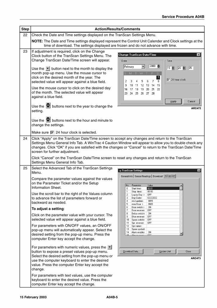
Service Procedure A04B
22 Check the Date and Time settings displayed on the TranScan Settings Menu.
NOTE: The Date and Time settings displayed represent the Control Unit Calender and Clock settings at the time of download. The settings displayed are frozen and do not advance with time.
23 If adjustment is required, click on the Change Clock button of the TranScan Settings Menu. The Change TranScan Date/Time screen will appear.
Use the button next to the month to display the month pop-up menu. Use the mouse cursor to click on the desired month of the year. The selected value will appear against a blue field.
Use the mouse cursor to click on the desired day of the month. The selected value will appear against a blue field.
Use the buttons next to the year to change the setting.
Use the buttons next to the hour and minute to change the settings.
Make sure 24 hour clock is selected.
24 Click “Apply” on the TranScan Date/Time screen to accept any changes and return to the TranScan Settings Menu General Info Tab. A WinTrac 4 Caution Window will appear to allow you to double check any changes. Click “OK” if you are satisfied with the changes or “Cancel” to return to the TranScan Date/Time screen for further adjustment.
Click “Cancel” on the TranScan Date/Time screen to reset any changes and return to the TranScan Settings Menu General Info Tab.
25 Select the Advanced Tab of the TranScan Settings Menu.
Compare the parameter values against the values on the Parameter Ticket and/or the Setup Information Sheet.
Use the scroll bar to the right of the Values column to advance the list of parameters forward or backward as needed.
To adjust a setting:
Click on the parameter value with your cursor. The selected value will appear against a blue field.
For parameters with ON/OFF values, an ON/OFF pop-up menu will automatically appear. Select the desired setting from the pop-up menu. Press the computer Enter key accept the change.
For parameters with numeric values, press the button to expose a preset values pop-up menu. Select the desired setting from the pop-up menu or use the computer keyboard to enter the desired value. Press the computer Enter key accept the change.
For parameters with text values, use the computer keyboard to enter the desired value. Press the computer Enter key accept the change.
Step Action/Results/Comments
A04B-515 February 2003
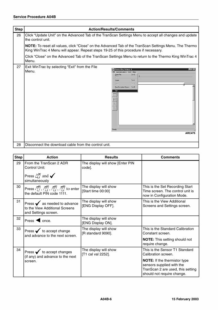
Service Procedure A04B
26 Click “Update Unit” on the Advanced Tab of the TranScan Settings Menu to accept all changes and update the control unit.
NOTE: To reset all values, click “Close” on the Advanced Tab of the TranScan Settings Menu. The Thermo King WinTrac 4 Menu will appear. Repeat steps 19-25 of this procedure if necessary.
Click “Close” on the Advanced Tab of the TranScan Settings Menu to return to the Thermo King WinTrac 4 Menu.
27 Exit WinTrac by selecting “Exit” from the File Menu.
28 Disconnect the download cable from the control unit.
Step Action Results Comments
29 From the TranScan 2 ADR Control Unit:
Press and simultaneously
The display will show [Enter PIN code].
30Press , , , to enter the default PIN code 1111.
The display will show [Start time 00:00]
This is the Set Recording Start Time screen. The control unit is now in Configuration Mode.
31Press as needed to advance to the View Additional Screens and Settings screen.
The display will show [ENG Display OFF].
This is the View Additional Screens and Settings screen.
32Press once.
The display will show [ENG Display ON].
33Press to accept changeand advance to the next screen.
The display will show [R standard 9090].
This is the Standard Calibration Constant screen.
NOTE: This setting should not require change.
34Press to accept changes(if any) and advance to the next screen.
The display will show [T1 cal val 2252].
This is the Sensor T1 Standard Calibration screen.
NOTE: If the thermistor type sensors supplied with the TranScan 2 are used, this setting should not require change.
Step Action/Results/Comments
A04B-6 15 February 2003

Service Procedure A04B
35Press to accept changes(if any) and advance to the next screen.
The display will show [T2 cal val 2252].
This is the Sensor T2 Standard Calibration screen.
NOTE: If the thermistor type sensors supplied with the TranScan 2 are used, this setting should not require change.
36Press to accept changes(if any) and advance to the next screen.
The display will show [T3 cal val 2252].
This is the Sensor T3 Standard Calibration screen.
NOTE: If the thermistor type sensors supplied with the TranScan 2 are used, this setting should not require change.
37Press to accept changes(if any) and advance to the next screen.
The display will show [T4 cal val 2252].
This is the Sensor T4 Standard Calibration screen.
NOTE: If the thermistor type sensors supplied with the TranScan 2 are used, this setting should not require change.
38Press to accept changes(if any) and advance to the next screen.
The display will show [PIN number 1111].
This is the Set Security Code screen.
If this is the correct setting, proceed to step 40.
39Press or as needed to position the cursor.
Press or as needed until the desired setting appears on the display panel.
The display will show any changes to this setting.
40Press to accept changes(if any) and advance to the next screen.
The display will show [Unit I/D (unit serial number)].
This is the Control Unit Identification Number screen.
If this is the correct setting, proceed to step 42.
NOTE: If the software (PROM Chip) is changed, this setting should be set to match the control unit serial number.
41Press or as needed to position the cursor.
Press or as needed until the desired setting appears on the display panel.
The display will show any changes to this setting.
42Press to accept changes(if any) and advance to the next screen.
The display will show [Baud rate 9600].
This is the Serial Port Communication Speed screen.
If this is the correct setting, proceed to step 44.
NOTE: This setting should be compatible with most current laptop and desktop computers.
Step Action Results Comments
A04B-715 February 2003
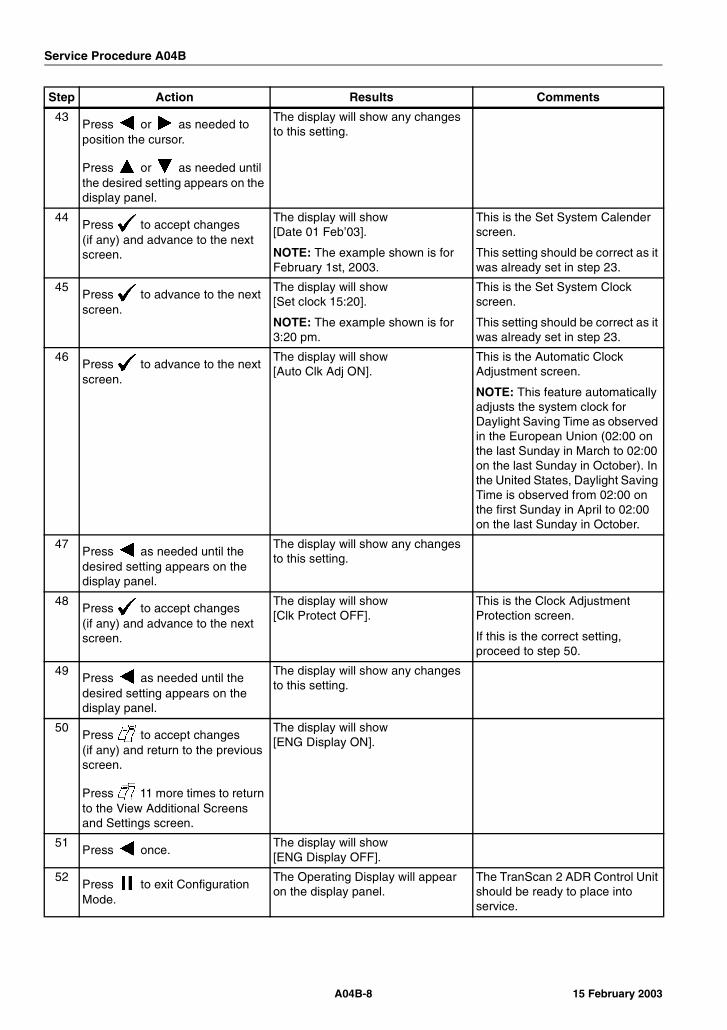
Service Procedure A04B
43Press or as needed to position the cursor.
Press or as needed until the desired setting appears on the display panel.
The display will show any changes to this setting.
44Press to accept changes(if any) and advance to the next screen.
The display will show [Date 01 Feb’03].
NOTE: The example shown is for February 1st, 2003.
This is the Set System Calender screen.
This setting should be correct as it was already set in step 23.
45Press to advance to the next screen.
The display will show [Set clock 15:20].
NOTE: The example shown is for 3:20 pm.
This is the Set System Clock screen.
This setting should be correct as it was already set in step 23.
46Press to advance to the next screen.
The display will show [Auto Clk Adj ON].
This is the Automatic Clock Adjustment screen.
NOTE: This feature automatically adjusts the system clock for Daylight Saving Time as observed in the European Union (02:00 on the last Sunday in March to 02:00 on the last Sunday in October). In the United States, Daylight Saving Time is observed from 02:00 on the first Sunday in April to 02:00 on the last Sunday in October.
47Press as needed until the desired setting appears on the display panel.
The display will show any changes to this setting.
48Press to accept changes(if any) and advance to the next screen.
The display will show [Clk Protect OFF].
This is the Clock Adjustment Protection screen.
If this is the correct setting, proceed to step 50.
49Press as needed until the desired setting appears on the display panel.
The display will show any changes to this setting.
50Press to accept changes(if any) and return to the previous screen.
Press 11 more times to return to the View Additional Screens and Settings screen.
The display will show [ENG Display ON].
51Press once.
The display will show [ENG Display OFF].
52Press to exit Configuration Mode.
The Operating Display will appear on the display panel.
The TranScan 2 ADR Control Unit should be ready to place into service.
Step Action Results Comments
A04B-8 15 February 2003

Service Procedure A05A
A05A Adjusting the Calender/Clock - Using the Control Unit Keys
Where UsedAll TranScan 2 ADR Control Units with Revision TS2-T410 Software
PurposeUse this procedure to adjust the system clock by using the Control Unit keys from either Operating Mode or Configuration Mode. For complete system setup instructions, see Service Procedure A04A & Service Procedure A04B in Section of this manual for additional information.
ImportantNOTE: Adjustments to the system clock will automatically start a new Journey File, [NEW FILE] will appear on the display panel for 5 seconds.
StepsFrom Operating Mode
Step Action Results Comments
1 Make sure the control unit is connected to supply power.
The Operating Display will appear on the display panel.
2 Press once. The display panel will show [PAUSING].
3 Press to adjust the clock hours.
If the clock protection feature is set to Off, the display panel will show [Hours + XX:XX] (current system time).
If this is the correct setting, proceed to step 5.
If the Clock Protection feature is set to On, the display panel will show [Protected] and clock adjustment from Operating Mode will be blocked.
4 Press as needed until the desired hour appears on the display panel.
If no other key is pressed within
15 seconds, or or is pressed, the control unit will accept any clock changes, automatically restart operation, and return to the Operating Display.
5 Press to adjust the clock minutes.
If the clock protection feature is set to Off, the display panel will show [Minutes + XX:XX] (current system time).
If this is the correct setting, proceed to step 7.
If the Clock Protection feature is set to On, the display panel will show [Protected] and clock adjustment from Operating Mode will be blocked.
A05A-115 February 2003
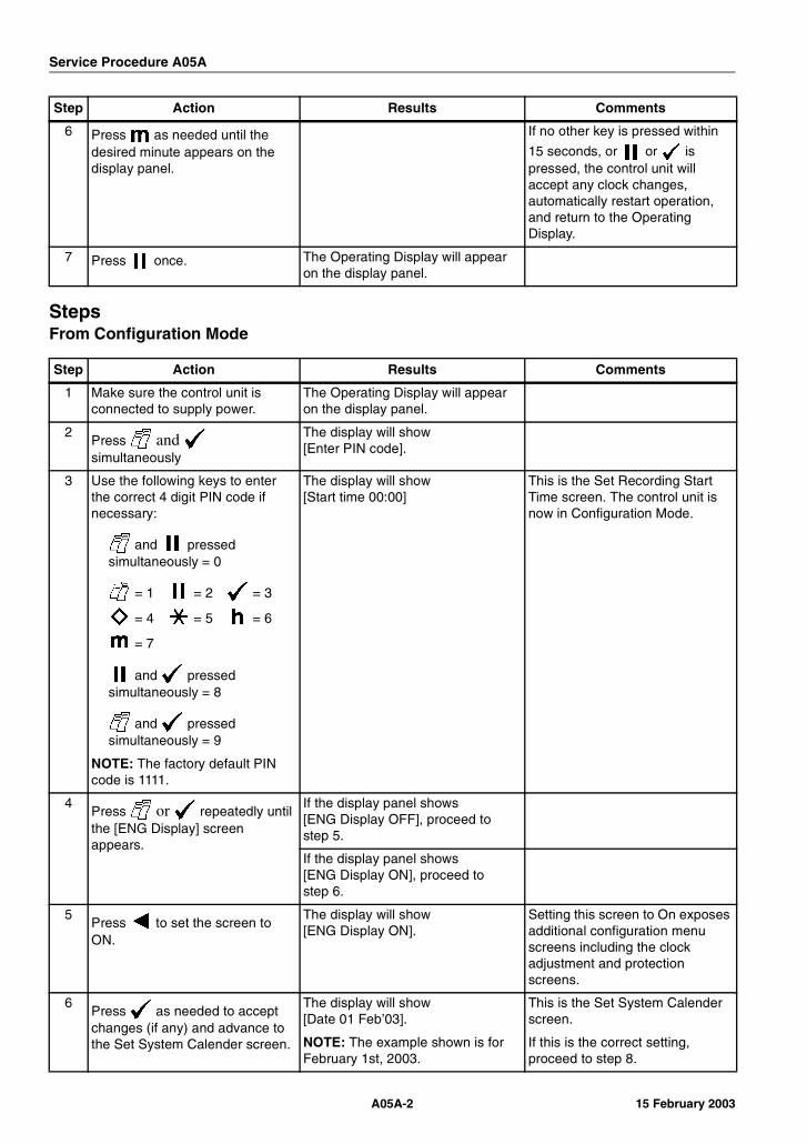
Service Procedure A05A
StepsFrom Configuration Mode
6 Press as needed until the desired minute appears on the display panel.
If no other key is pressed within
15 seconds, or or is pressed, the control unit will accept any clock changes, automatically restart operation, and return to the Operating Display.
7 Press once. The Operating Display will appear on the display panel.
Step Action Results Comments
1 Make sure the control unit is connected to supply power.
The Operating Display will appear on the display panel.
2Press and simultaneously
The display will show [Enter PIN code].
3 Use the following keys to enter the correct 4 digit PIN code if necessary:
and pressed simultaneously = 0
= 1 = 2 = 3
= 4 = 5 = 6
= 7
and pressed simultaneously = 8
and pressed simultaneously = 9
NOTE: The factory default PIN code is 1111.
The display will show [Start time 00:00]
This is the Set Recording Start Time screen. The control unit is now in Configuration Mode.
4Press or repeatedly until the [ENG Display] screen appears.
If the display panel shows [ENG Display OFF], proceed to step 5.
If the display panel shows [ENG Display ON], proceed to step 6.
5Press to set the screen to ON.
The display will show [ENG Display ON].
Setting this screen to On exposes additional configuration menu screens including the clock adjustment and protection screens.
6Press as needed to accept changes (if any) and advance to the Set System Calender screen.
The display will show [Date 01 Feb’03].
NOTE: The example shown is for February 1st, 2003.
This is the Set System Calender screen.
If this is the correct setting, proceed to step 8.
Step Action Results Comments
A05A-2 15 February 2003
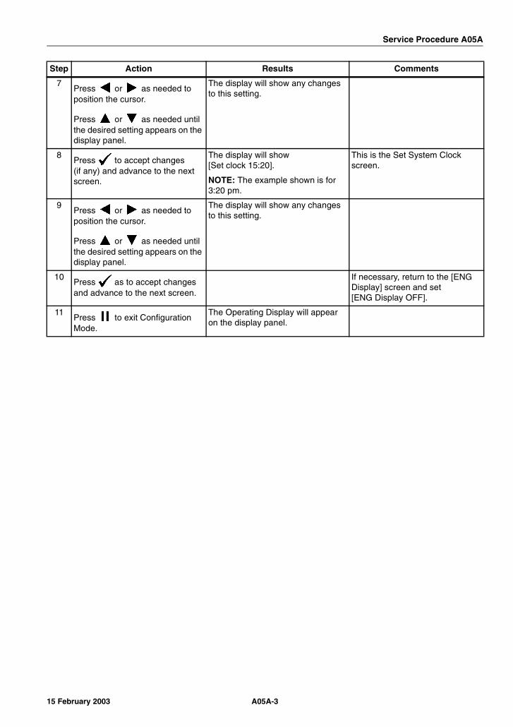
Service Procedure A05A
7Press or as needed to position the cursor.
Press or as needed until the desired setting appears on the display panel.
The display will show any changes to this setting.
8Press to accept changes(if any) and advance to the next screen.
The display will show [Set clock 15:20].
NOTE: The example shown is for 3:20 pm.
This is the Set System Clock screen.
9Press or as needed to position the cursor.
Press or as needed until the desired setting appears on the display panel.
The display will show any changes to this setting.
10Press as to accept changes and advance to the next screen.
If necessary, return to the [ENG Display] screen and set [ENG Display OFF].
11Press to exit Configuration Mode.
The Operating Display will appear on the display panel.
Step Action Results Comments
A05A-315 February 2003

Service Procedure A05A
A05A-4 15 February 2003
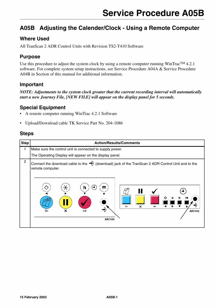
Service Procedure A05B
A05B Adjusting the Calender/Clock - Using a Remote Computer
Where UsedAll TranScan 2 ADR Control Units with Revision TS2-T410 Software
PurposeUse this procedure to adjust the system clock by using a remote computer running WinTracTM 4.2.1 software. For complete system setup instructions, see Service Procedure A04A & Service Procedure A04B in Section of this manual for additional information.
ImportantNOTE: Adjustments to the system clock greater that the current recording interval will automatically start a new Journey File, [NEW FILE] will appear on the display panel for 5 seconds.
Special Equipment• A remote computer running WinTrac 4.2.1 Software
• Upload/Download cable TK Service Part No. 204-1086
Steps
Step Action/Results/Comments
1 Make sure the control unit is connected to supply power.
The Operating Display will appear on the display panel.
2Connect the download cable to the (download) jack of the TranScan 2 ADR Control Unit and to the remote computer.
A05B-115 February 2003

Service Procedure A05B
3 From the remote computer:
Open WinTrac on the remote computer. The Thermo King WinTrac 4 Menu will appear.
4
Click the icon or select Seek Device from the WinTrac Communications Menu.
NOTE: Make sure the Com Port selected on the WinTrac Global Settings Communications tab is the same as the Com Port used to connect the download cable.
5 The Communicating screen should appear in a few moments. [Self Test O.K.] will appear on the control unit display panel during download.
NOTE: WinTrac is used to communicate with a variety of Thermo King devices. You can track the device search by viewing the status bar at the bottom of the screen. Connection to the TranScan 2 Control Unit should occur during the “Searching for CCI Devices” phase.
6 Once the TranScan settings have been downloaded (about 1 minute), the TranScan Settings Menu General Info Tab will appear.
Step Action/Results/Comments
A05B-2 15 February 2003

Service Procedure A05B
7 NOTE: The Date and Time settings displayed represent the Control Unit Calender and Clock settings at the time of download. The settings displayed are frozen and do not advance with time.
Click on the Change Clock button of the TranScan Settings Menu. The Change TranScan Date/Time screen will appear.
Use the button next to the month to display the month pop-up menu. Use the mouse cursor to click on the desired month of the year. The selected value will appear against a blue field.
Use the mouse cursor to click on the desired day of the month. The selected value will appear against a blue field.
Use the buttons next to the year to change the setting.
Use the buttons next to the hour and minute to change the settings.
Make sure 24 hour clock is selected.
8 Click “Apply” on the TranScan Date/Time screen to accept any changes and return to the TranScan Settings Menu General Info Tab. A WinTrac 4 Caution Window will appear to allow you to double check any changes. Click “OK” if you are satisfied with the changes or “Cancel” to return to the TranScan Date/Time screen for further adjustment.
Click “Cancel” on the TranScan Date/Time screen to reset any changes and return to the TranScan Settings Menu General Info Tab.
9 Click “Close” on the General Info Tab of the TranScan Settings Menu to return to the Thermo King WinTrac 4 Menu.
10 Exit WinTrac by selecting “Exit” from the File Menu.
11 Disconnect the download cable from the control unit.
Step Action/Results/Comments
A05B-315 February 2003

Service Procedure A05B
A05B-4 15 February 2003
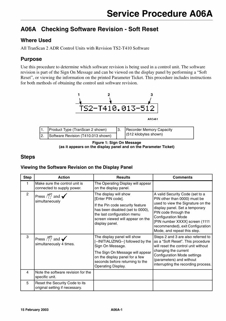
Service Procedure A06A
A06A Checking Software Revision - Soft Reset
Where UsedAll TranScan 2 ADR Control Units with Revision TS2-T410 Software
PurposeUse this procedure to determine which software revision is being used in a control unit. The software revision is part of the Sign On Message and can be viewed on the display panel by performing a “Soft Reset”, or viewing the information on the printed Parameter Ticket. This procedure includes instructions for both methods of obtaining the control unit software revision.
Steps
Viewing the Software Revision on the Display Panel
1. Product Type (TranScan 2 shown) 3. Recorder Memory Capacity(512 kilobytes shown)2. Software Revision (T410.013 shown)
Figure 1: Sign On Message(as it appears on the display panel and on the Parameter Ticket)
Step Action Results Comments
1 Make sure the control unit is connected to supply power.
The Operating Display will appear on the display panel.
2Press and simultaneously
The display will show [Enter PIN code].
If the Pin code security feature has been disabled (set to 0000), the last configuration menu screen viewed will appear on the display panel.
A valid Security Code (set to a PIN other than 0000) must be used to view the Signature on the display panel. Set a temporary PIN code through the Configuration Mode [PIN number XXXX] screen (1111 recommended), exit Configuration Mode, and repeat this step.
3Press and simultaneously 4 times.
The display panel will show [--INITIALIZING--] followed by the Sign On Message.
The Sign On Message will appear on the display panel for a few seconds before returning to the Operating Display.
Steps 2 and 3 are also referred to as a “Soft Reset”. This procedure will reset the control unit without changing the current Configuration Mode settings (parameters) and without interrupting the recording process.
4 Note the software revision for the specific unit.
5 Reset the Security Code to its original setting if necessary.
1 2 3
A06A-115 February 2003
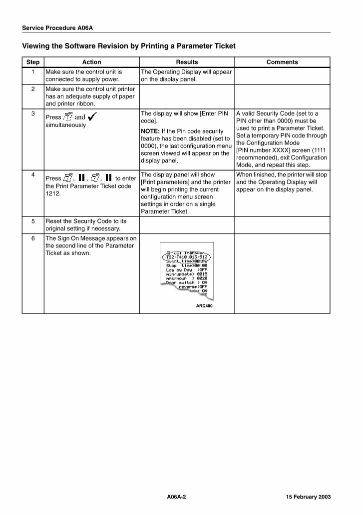
Service Procedure A06A
Viewing the Software Revision by Printing a Parameter Ticket
Step Action Results Comments
1 Make sure the control unit is connected to supply power.
The Operating Display will appear on the display panel.
2 Make sure the control unit printer has an adequate supply of paper and printer ribbon.
3Press and simultaneously
The display will show [Enter PIN code].
NOTE: If the Pin code security feature has been disabled (set to 0000), the last configuration menu screen viewed will appear on the display panel.
A valid Security Code (set to a PIN other than 0000) must be used to print a Parameter Ticket. Set a temporary PIN code through the Configuration Mode [PIN number XXXX] screen (1111 recommended), exit Configuration Mode, and repeat this step.
4Press , , , to enter the Print Parameter Ticket code 1212.
The display panel will show [Print parameters] and the printer will begin printing the current configuration menu screen settings in order on a single Parameter Ticket.
When finished, the printer will stop and the Operating Display will appear on the display panel.
5 Reset the Security Code to its original setting if necessary.
6 The Sign On Message appears on the second line of the Parameter Ticket as shown.
A06A-2 15 February 2003
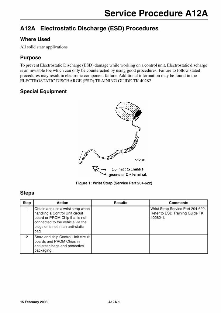
Service Procedure A12A
A12A Electrostatic Discharge (ESD) Procedures
Where UsedAll solid state applications
PurposeTo prevent Electrostatic Discharge (ESD) damage while working on a control unit. Electrostatic discharge is an invisible foe which can only be counteracted by using good procedures. Failure to follow stated procedures may result in electronic component failure. Additional information may be found in the ELECTROSTATIC DISCHARGE (ESD) TRAINING GUIDE TK 40282.
Special Equipment
Figure 1: Wrist Strap (Service Part 204-622)
Steps
Step Action Results Comments
1 Obtain and use a wrist strap when handling a Control Unit circuit board or PROM Chip that is not connected to the vehicle via the plugs or is not in an anti-static bag.
Wrist Strap Service Part 204-622. Refer to ESD Training Guide TK 40282-1.
2 Store and ship Control Unit circuit boards and PROM Chips in anti-static bags and protective packaging.
A12A-115 February 2003

Service Procedure A12A
A12A-2 15 February 2003
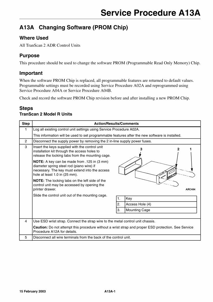
Service Procedure A13A
A13A Changing Software (PROM Chip)
Where UsedAll TranScan 2 ADR Control Units
PurposeThis procedure should be used to change the software PROM (Programmable Read Only Memory) Chip.
ImportantWhen the software PROM Chip is replaced, all programmable features are returned to default values. Programmable settings must be recorded using Service Procedure A02A and reprogrammed using Service Procedure A04A or Service Procedure A04B.
Check and record the software PROM Chip revision before and after installing a new PROM Chip.
StepsTranScan 2 Model R Units
Step Action/Results/Comments
1 Log all existing control unit settings using Service Procedure A02A.
This information will be used to set programmable features after the new software is installed.
2 Disconnect the supply power by removing the 2 in-line supply power fuses.
3 Insert the keys supplied with the control unit installation kit through the access holes to release the locking tabs from the mounting cage.
NOTE: A key can be made from .125 in (3 mm) diameter spring steel rod (piano wire) if necessary. The key must extend into the access hole at least 1.0 in (25 mm).
NOTE: The locking tabs on the left side of the control unit may be accessed by opening the printer drawer.
Slide the control unit out of the mounting cage.
4 Use ESD wrist strap. Connect the strap wire to the metal control unit chassis.
Caution: Do not attempt this procedure without a wrist strap and proper ESD protection. See Service Procedure A12A for details.
5 Disconnect all wire terminals from the back of the control unit.
1. Key
2. Access Hole (4)
3. Mounting Cage
123
A13A-115 February 2003
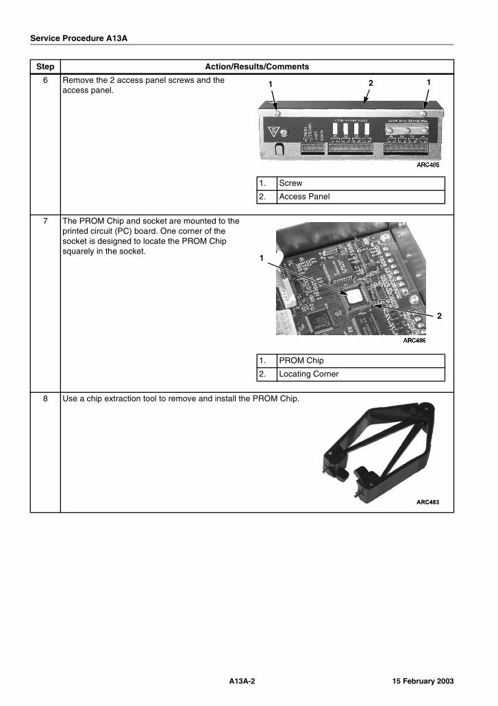
Service Procedure A13A
6 Remove the 2 access panel screws and the access panel.
7 The PROM Chip and socket are mounted to the printed circuit (PC) board. One corner of the socket is designed to locate the PROM Chip squarely in the socket.
8 Use a chip extraction tool to remove and install the PROM Chip.
Step Action/Results/Comments
1. Screw
2. Access Panel
1 2 1
1. PROM Chip
2. Locating Corner
1
2
A13A-2 15 February 2003
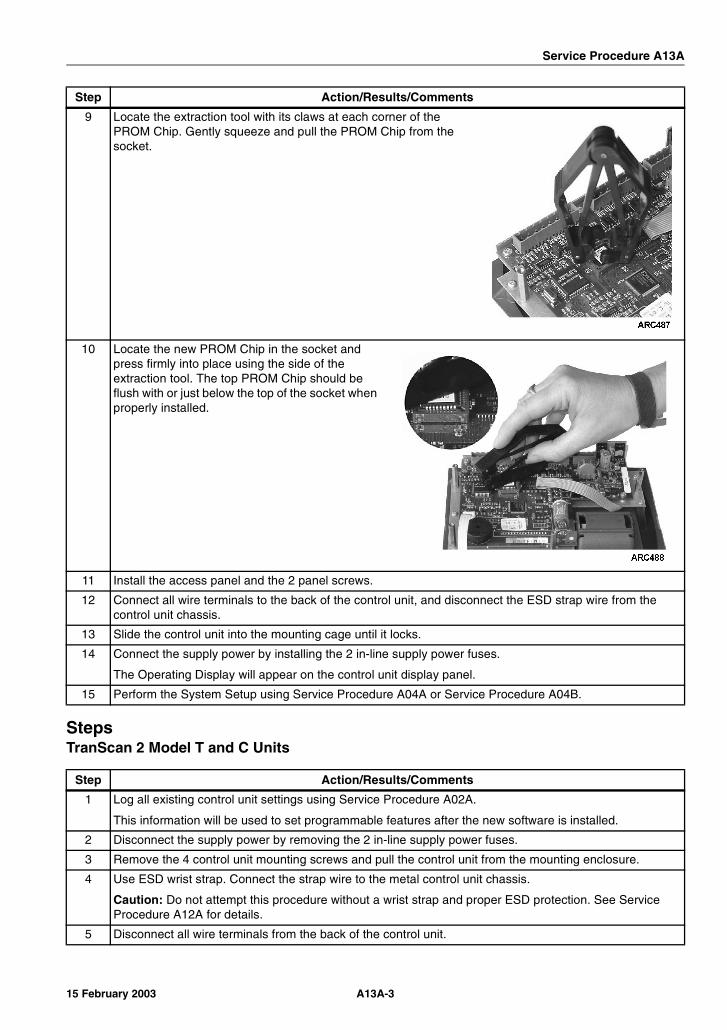
Service Procedure A13A
StepsTranScan 2 Model T and C Units
9 Locate the extraction tool with its claws at each corner of the PROM Chip. Gently squeeze and pull the PROM Chip from the socket.
10 Locate the new PROM Chip in the socket and press firmly into place using the side of the extraction tool. The top PROM Chip should be flush with or just below the top of the socket when properly installed.
11 Install the access panel and the 2 panel screws.
12 Connect all wire terminals to the back of the control unit, and disconnect the ESD strap wire from the control unit chassis.
13 Slide the control unit into the mounting cage until it locks.
14 Connect the supply power by installing the 2 in-line supply power fuses.
The Operating Display will appear on the control unit display panel.
15 Perform the System Setup using Service Procedure A04A or Service Procedure A04B.
Step Action/Results/Comments
1 Log all existing control unit settings using Service Procedure A02A.
This information will be used to set programmable features after the new software is installed.
2 Disconnect the supply power by removing the 2 in-line supply power fuses.
3 Remove the 4 control unit mounting screws and pull the control unit from the mounting enclosure.
4 Use ESD wrist strap. Connect the strap wire to the metal control unit chassis.
Caution: Do not attempt this procedure without a wrist strap and proper ESD protection. See Service Procedure A12A for details.
5 Disconnect all wire terminals from the back of the control unit.
Step Action/Results/Comments
A13A-315 February 2003
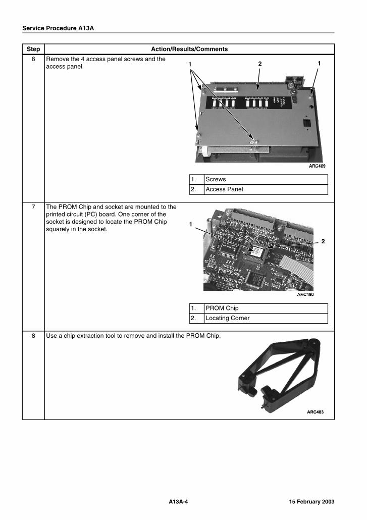
Service Procedure A13A
6 Remove the 4 access panel screws and the access panel.
7 The PROM Chip and socket are mounted to the printed circuit (PC) board. One corner of the socket is designed to locate the PROM Chip squarely in the socket.
8 Use a chip extraction tool to remove and install the PROM Chip.
Step Action/Results/Comments
1. Screws
2. Access Panel
1 12
1. PROM Chip
2. Locating Corner
1
2
A13A-4 15 February 2003

Service Procedure A13A
9 Locate the extraction tool with its claws at each corner of the PROM Chip. Gently squeeze and pull the PROM Chip from the socket.
10 Locate the new PROM Chip in the socket and press firmly into place using the side of the extraction tool. The top PROM Chip should be flush with or just below the top of the socket when properly installed.
11 Install the access panel and the 4 panel screws.
12 Connect all wire terminals to the back of the control unit, and disconnect the ESD strap wire from the control unit chassis.
13 Position the control unit into the mounting enclosure and install the 4 mounting screws.
14 Connect the supply power by installing the 2 in-line supply power fuses.
The Operating Display will appear on the control unit display panel.
15 Perform the System Setup using Service Procedure A04A or Service Procedure A04B.
Step Action/Results/Comments
A13A-515 February 2003

Service Procedure A13A
A13A-6 15 February 2003
Service Procedure A26A
A26A Welding on Units Equipped with TranScan 2 Control Units
Where UsedAll trucks and trailers equipped with TranScan 2 ADR Control Units
PurposeTo prevent damage to the TranScan 2 ADR Control Unit during welding operations. Electric welding generates extremely high amperage currents which can damage electrical and electronic components. To minimize the possibility of damage, the following procedures must be followed.
ImportantFollow this procedure in addition to any welding procedure recommended for the refrigeration system.
Before Welding
After Welding
Step Action Results Comments
1 Turn the refrigeration unit Off.
2 Disconnect all connectors from the TranScan 2 ADR Control Unit.
3 If welding close enough to a Control Unit that sparks could damage it, remove the module.
4 Connect the welder ground cable as close as possible to the area where the welding is to be performed. Move the welder ground cable as required.
Step Action Results Comments
1 Reinstall the Control Unit if it was removed.
2 Reconnect all connectors.
3 Verify operation of the TranScan 2 ADR Control Unit.
A26A-115 February 2003

Service Procedure A26A
A26A-2 15 February 2003
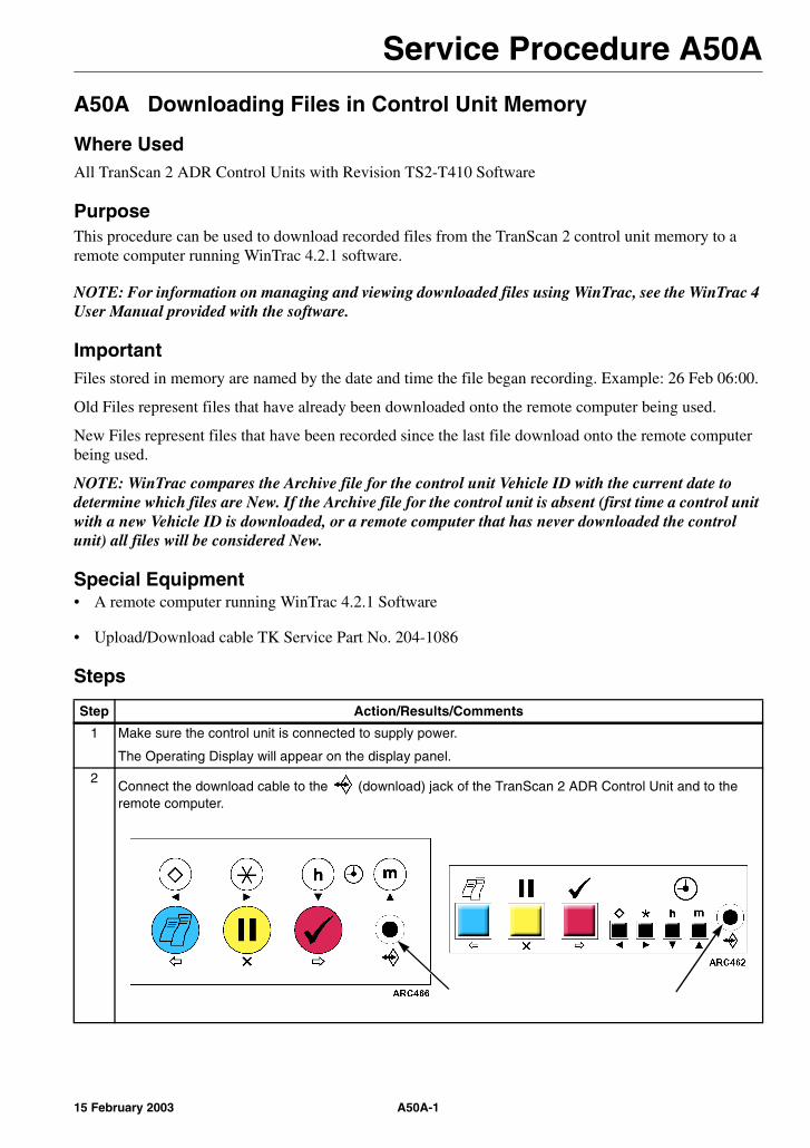
Service Procedure A50A
A50A Downloading Files in Control Unit Memory
Where UsedAll TranScan 2 ADR Control Units with Revision TS2-T410 Software
PurposeThis procedure can be used to download recorded files from the TranScan 2 control unit memory to a remote computer running WinTrac 4.2.1 software.
NOTE: For information on managing and viewing downloaded files using WinTrac, see the WinTrac 4 User Manual provided with the software.
ImportantFiles stored in memory are named by the date and time the file began recording. Example: 26 Feb 06:00.
Old Files represent files that have already been downloaded onto the remote computer being used.
New Files represent files that have been recorded since the last file download onto the remote computer being used.
NOTE: WinTrac compares the Archive file for the control unit Vehicle ID with the current date to determine which files are New. If the Archive file for the control unit is absent (first time a control unit with a new Vehicle ID is downloaded, or a remote computer that has never downloaded the control unit) all files will be considered New.
Special Equipment• A remote computer running WinTrac 4.2.1 Software
• Upload/Download cable TK Service Part No. 204-1086
Steps
Step Action/Results/Comments
1 Make sure the control unit is connected to supply power.
The Operating Display will appear on the display panel.
2Connect the download cable to the (download) jack of the TranScan 2 ADR Control Unit and to the remote computer.
A50A-115 February 2003

Service Procedure A50A
3 From the remote computer:
Open WinTrac on the remote computer. The Thermo King WinTrac 4 Menu will appear.
4
Click the icon or select Seek Device from the WinTrac Communications Menu.
NOTE: Make sure the Com Port selected on the WinTrac Global Settings Communications tab is the same as the Com Port used to connect the download cable.
5 The Communicating screen should appear in a few moments. [Self Test O.K.] will appear on the control unit display panel during download.
NOTE: WinTrac is used to communicate with a variety of Thermo King devices. You can track the device search by viewing the status bar at the bottom of the screen. Connection to the TranScan 2 Control Unit should occur during the “Searching for CCI Devices” phase.
6 Once the TranScan settings have been downloaded (about 1 minute), the TranScan Settings Menu General Info Tab will appear.
The number of Old Files and New Files appears in the Memory Usage area (lower left) of the General Info Tab. 339 Old Files and 6 New Files exist in the TranScan 2 control unit memory in the example shown.
Old Files represent files that have already been downloaded onto the remote computer being used.
New Files represent files that have been recorded since the last file download onto the remote computer being used.
Step Action/Results/Comments
A50A-2 15 February 2003
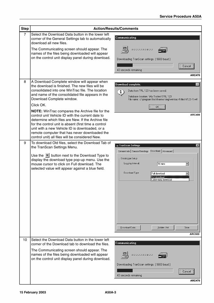
Service Procedure A50A
7 Select the Download Data button in the lower left corner of the General Settings tab to automatically download all new files.
The Communicating screen should appear. The names of the files being downloaded will appear on the control unit display panel during download.
8 A Download Complete window will appear when the download is finished. The new files will be consolidated into one WinTrac file. The location and name of the consolidated file appears in the Download Complete window.
Click OK.
NOTE: WinTrac compares the Archive file for the control unit Vehicle ID with the current date to determine which files are New. If the Archive file for the control unit is absent (first time a control unit with a new Vehicle ID is downloaded, or a remote computer that has never downloaded the control unit) all files will be considered New.
9 To download Old files, select the Download Tab of the TranScan Settings Menu.
Use the button next to the Download Type to display the download type pop-up menu. Use the mouse cursor to click on Full download. The selected value will appear against a blue field.
10 Select the Download Data button in the lower left corner of the Download tab to download the files.
The Communicating screen should appear. The names of the files being downloaded will appear on the control unit display panel during download.
Step Action/Results/Comments
A50A-315 February 2003

Service Procedure A50A
11 A Download Complete window will appear when the download is finished. The new files will be consolidated into one WinTrac file. The location and name of the consolidated file appears in the Download Complete window.
Click OK.
12 Click “Close” on the Download Tab or General Info Tab of the TranScan Settings Menu to return to the Thermo King WinTrac 4 Menu.
13 Exit WinTrac by selecting “Exit” from the File Menu.
14 Disconnect the download cable from the control unit.
Step Action/Results/Comments
A50A-4 15 February 2003
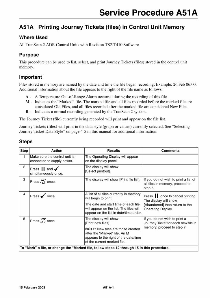
Service Procedure A51A
A51A Printing Journey Tickets (files) in Control Unit Memory
Where UsedAll TranScan 2 ADR Control Units with Revision TS2-T410 Software
PurposeThis procedure can be used to list, select, and print Journey Tickets (files) stored in the control unit memory.
ImportantFiles stored in memory are named by the date and time the file began recording. Example: 26 Feb 06:00.Additional information about the file appears to the right of the file name as follows:
A - A Temperature Out-of-Range Alarm occurred during the recording of this fileM - Indicates the “Marked” file. The marked file and all files recorded before the marked file are
considered Old Files, and all files recorded after the marked file are considered New Files.R - Indicates a normal recording generated by the TranScan 2 system.
The Journey Ticket (file) currently being recorded will print and appear on the file list.
Journey Tickets (files) will print in the data style (graph or values) currently selected. See “Selecting Journey Ticket Data Style” on page 4-5 in this manual for additional information.
Steps
Step Action Results Comments
1 Make sure the control unit is connected to supply power.
The Operating Display will appear on the display panel.
2Press and simultaneously once.
The display will show [Select printout].
3Press once.
The display will show [Print file list]. If you do not wish to print a list of all files in memory, proceed to step 5.
4Press once.
A list of all files currently in memory will begin to print.
The date and start time of each file will appear on the list. The files will appear on the list in date/time order.
Press once to cancel printing. The display will show [Abandoned] then return to the Operating Display.
5Press once.
The display will show [Print new files].
NOTE: New files are those created after the “Marked” file. An M appears to the right of the date/time of the current marked file.
If you do not wish to print a Journey Ticket for each new file in memory, proceed to step 7.
To “Mark” a file, or change the “Marked file, follow steps 12 through 15 in this procedure.
A51A-115 February 2003
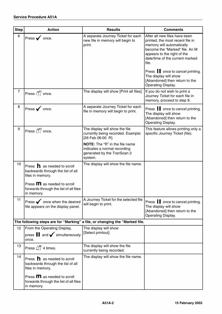
Service Procedure A51A
6Press once.
A separate Journey Ticket for each new file in memory will begin to print.
After all new files have been printed, the most recent file in memory will automatically become the “Marked” file. An M appears to the right of the date/time of the current marked file.
Press once to cancel printing. The display will show [Abandoned] then return to the Operating Display.
7Press once.
The display will show [Print all files]. If you do not wish to print a Journey Ticket for each file in memory, proceed to step 9.
8Press once.
A separate Journey Ticket for each file in memory will begin to print.
Press once to cancel printing. The display will show [Abandoned] then return to the Operating Display.
9Press once.
The display will show the file currently being recorded. Example: [26 Feb 06:00 R].
NOTE: The “R” in the file name indicates a normal recording generated by the TranScan 2 system.
This feature allows printing only a specific Journey Ticket (file).
10Press as needed to scroll backwards through the list of all files in memory.
Press as needed to scroll forwards through the list of all files in memory.
The display will show the file name.
11Press once when the desired file appears on the display panel.
A Journey Ticket for the selected file will begin to print.
Press once to cancel printing. The display will show [Abandoned] then return to the Operating Display.
The following steps are for “Marking” a file, or changing the “Marked file.
12 From the Operating Display,
press and simultaneously once.
The display will show [Select printout].
13Press 4 times.
The display will show the file currently being recorded.
14Press as needed to scroll backwards through the list of all files in memory.
Press as needed to scroll forwards through the list of all files in memory.
The display will show the file name.
Step Action Results Comments
A51A-2 15 February 2003
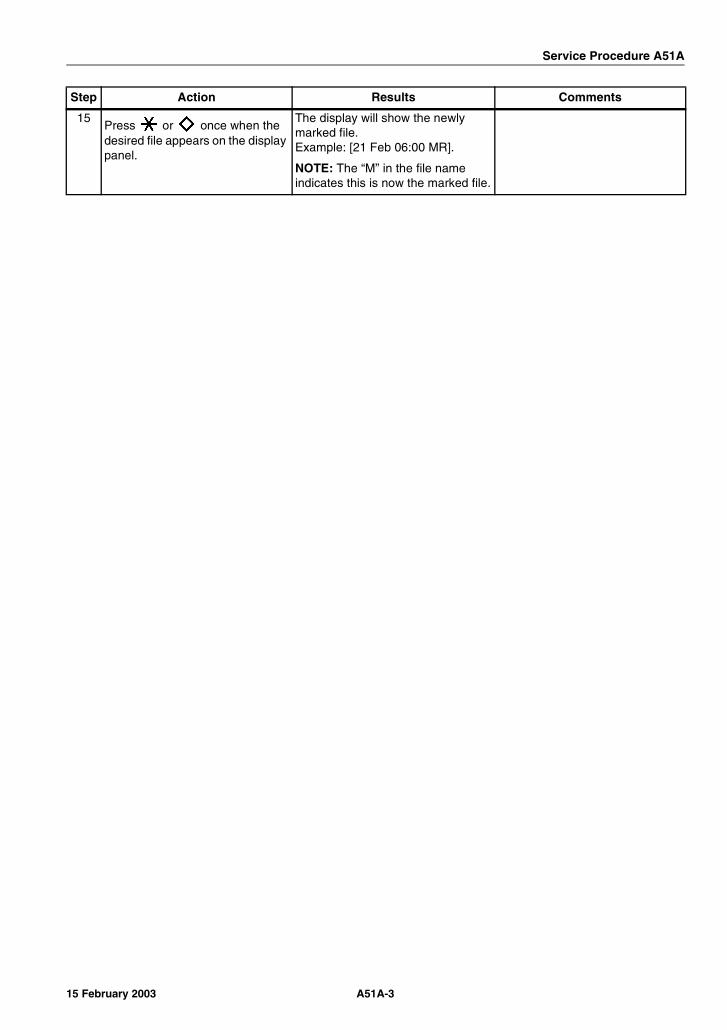
Service Procedure A51A
15Press or once when the desired file appears on the display panel.
The display will show the newly marked file.Example: [21 Feb 06:00 MR].
NOTE: The “M” in the file name indicates this is now the marked file.
Step Action Results Comments
A51A-315 February 2003

Service Procedure A51A
A51A-4 15 February 2003
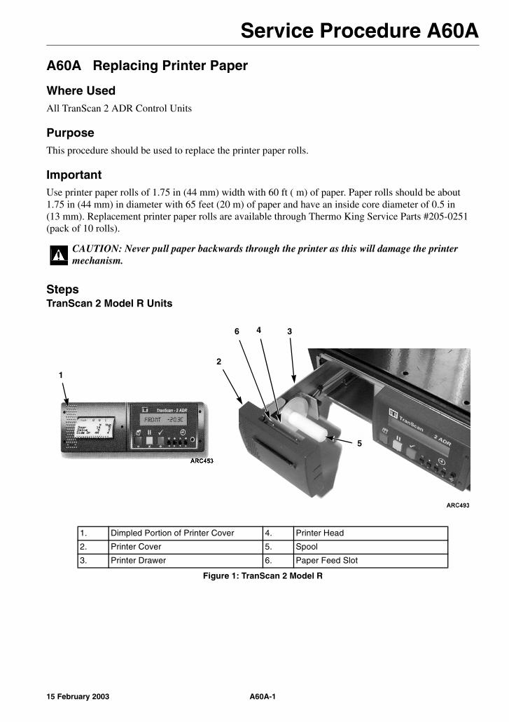
Service Procedure A60A
A60A Replacing Printer Paper
Where UsedAll TranScan 2 ADR Control Units
PurposeThis procedure should be used to replace the printer paper rolls.
ImportantUse printer paper rolls of 1.75 in (44 mm) width with 60 ft ( m) of paper. Paper rolls should be about 1.75 in (44 mm) in diameter with 65 feet (20 m) of paper and have an inside core diameter of 0.5 in (13 mm). Replacement printer paper rolls are available through Thermo King Service Parts #205-0251 (pack of 10 rolls).
StepsTranScan 2 Model R Units
CAUTION: Never pull paper backwards through the printer as this will damage the printer mechanism.
1. Dimpled Portion of Printer Cover 4. Printer Head
2. Printer Cover 5. Spool
3. Printer Drawer 6. Paper Feed Slot
Figure 1: TranScan 2 Model R
1
5
346
2
A60A-115 February 2003
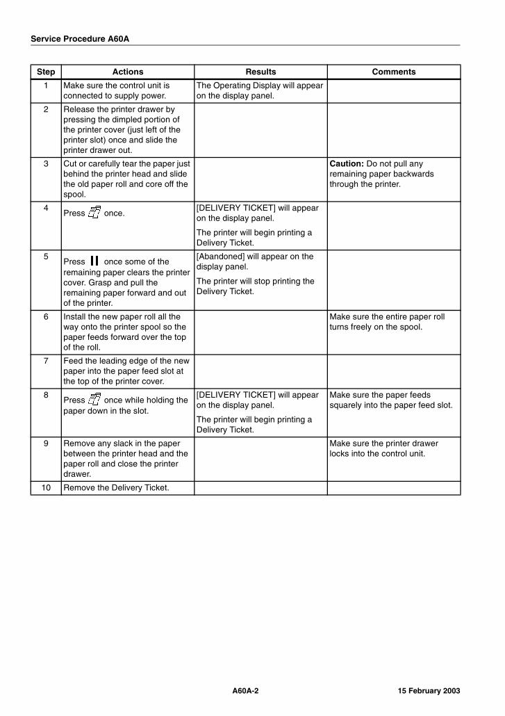
Service Procedure A60A
Step Actions Results Comments
1 Make sure the control unit is connected to supply power.
The Operating Display will appear on the display panel.
2 Release the printer drawer by pressing the dimpled portion of the printer cover (just left of the printer slot) once and slide the printer drawer out.
3 Cut or carefully tear the paper just behind the printer head and slide the old paper roll and core off the spool.
Caution: Do not pull any remaining paper backwards through the printer.
4Press once.
[DELIVERY TICKET] will appear on the display panel.
The printer will begin printing a Delivery Ticket.
5Press once some of the remaining paper clears the printer cover. Grasp and pull the remaining paper forward and out of the printer.
[Abandoned] will appear on the display panel.
The printer will stop printing the Delivery Ticket.
6 Install the new paper roll all the way onto the printer spool so the paper feeds forward over the top of the roll.
Make sure the entire paper roll turns freely on the spool.
7 Feed the leading edge of the new paper into the paper feed slot at the top of the printer cover.
8Press once while holding the paper down in the slot.
[DELIVERY TICKET] will appear on the display panel.
The printer will begin printing a Delivery Ticket.
Make sure the paper feeds squarely into the paper feed slot.
9 Remove any slack in the paper between the printer head and the paper roll and close the printer drawer.
Make sure the printer drawer locks into the control unit.
10 Remove the Delivery Ticket.
A60A-2 15 February 2003

Service Procedure A60A
StepsTranScan 2 Model T and C Units
1. Ticket Slot 4. Paper Roll Mount
2. Printer Cover 5. Paper Feed Slot
3. Printer Head
Figure 2: TranScan 2 Model C and T
Step Actions Results Comments
1 Make sure the control unit is connected to supply power.
The Operating Display will appear on the display panel.
2 Use the finger cutout (just below the ticket slot) and lift the printer cover open.
3 Cut or carefully tear the paper just below the printer head and pull the remaining paper outward through the printer.
Caution: Do not pull any remaining paper downwards through the printer.
4 Spread the paper roll mounts and remove the old paper roll and core.
5 Install the new paper roll in the mounts so the paper feeds upward over the back of the roll.
Make sure the entire paper roll turns freely in the mounts.
6 Feed the leading edge of the new paper into the paper feed slot at the bottom of the printer head.
7Press once while holding the paper up in the slot.
[DELIVERY TICKET] will appear on the display panel.
The printer will begin printing a Delivery Ticket.
Make sure the paper feeds squarely into the paper feed slot.
1
2
3
5
4
4
A60A-315 February 2003

Service Procedure A60A
8 Remove any slack in the paper between the printer head and the paper roll, feed the leading edge of the paper through the ticket slot and close the printer cover.
Make sure the printer cover locks into the control unit.
9 Remove the Delivery Ticket.
Step Actions Results Comments
A60A-4 15 February 2003
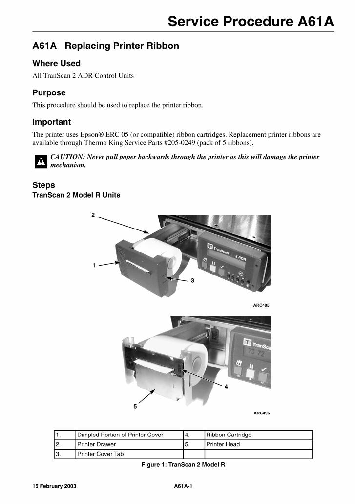
Service Procedure A61A
A61A Replacing Printer Ribbon
Where UsedAll TranScan 2 ADR Control Units
PurposeThis procedure should be used to replace the printer ribbon.
ImportantThe printer uses Epson® ERC 05 (or compatible) ribbon cartridges. Replacement printer ribbons are available through Thermo King Service Parts #205-0249 (pack of 5 ribbons).
StepsTranScan 2 Model R Units
CAUTION: Never pull paper backwards through the printer as this will damage the printer mechanism.
1. Dimpled Portion of Printer Cover 4. Ribbon Cartridge
2. Printer Drawer 5. Printer Head
3. Printer Cover Tab
Figure 1: TranScan 2 Model R
1
2
3
5
4
A61A-115 February 2003
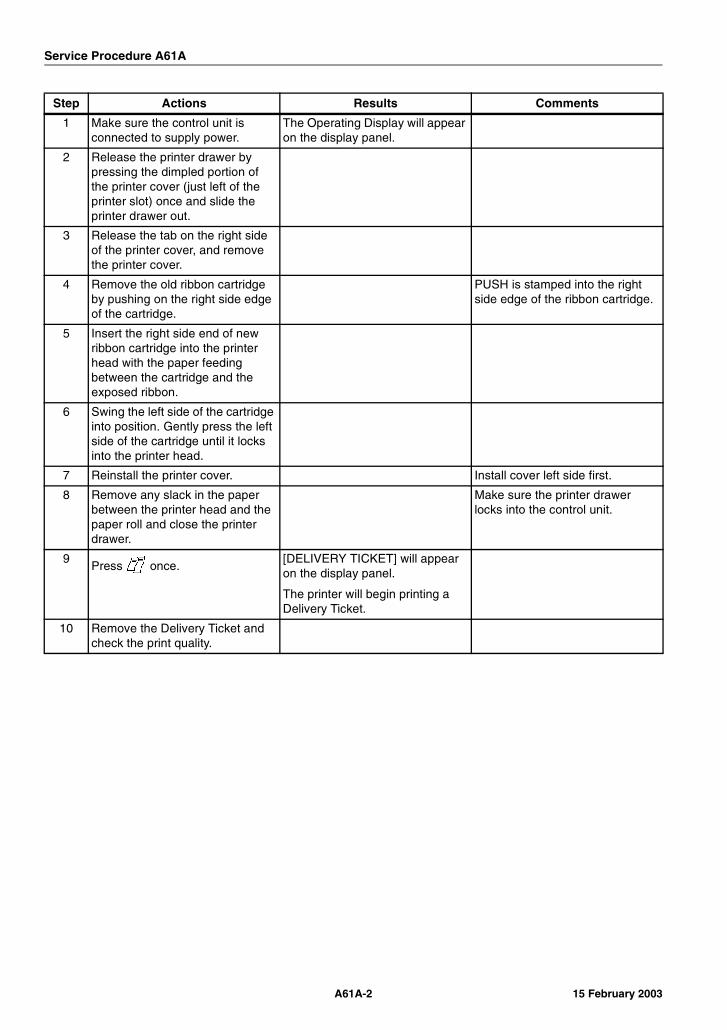
Service Procedure A61A
Step Actions Results Comments
1 Make sure the control unit is connected to supply power.
The Operating Display will appear on the display panel.
2 Release the printer drawer by pressing the dimpled portion of the printer cover (just left of the printer slot) once and slide the printer drawer out.
3 Release the tab on the right side of the printer cover, and remove the printer cover.
4 Remove the old ribbon cartridge by pushing on the right side edge of the cartridge.
PUSH is stamped into the right side edge of the ribbon cartridge.
5 Insert the right side end of new ribbon cartridge into the printer head with the paper feeding between the cartridge and the exposed ribbon.
6 Swing the left side of the cartridge into position. Gently press the left side of the cartridge until it locks into the printer head.
7 Reinstall the printer cover. Install cover left side first.
8 Remove any slack in the paper between the printer head and the paper roll and close the printer drawer.
Make sure the printer drawer locks into the control unit.
9Press once.
[DELIVERY TICKET] will appear on the display panel.
The printer will begin printing a Delivery Ticket.
10 Remove the Delivery Ticket and check the print quality.
A61A-2 15 February 2003
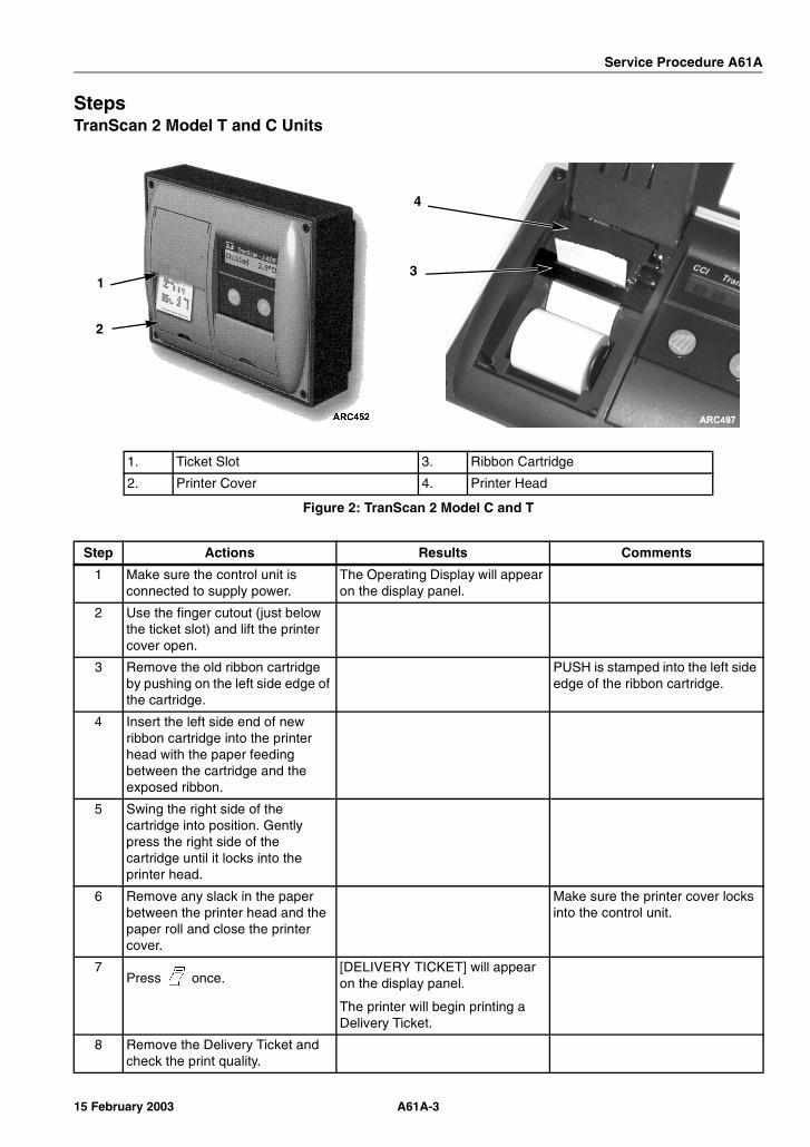
Service Procedure A61A
StepsTranScan 2 Model T and C Units
1. Ticket Slot 3. Ribbon Cartridge
2. Printer Cover 4. Printer Head
Figure 2: TranScan 2 Model C and T
Step Actions Results Comments
1 Make sure the control unit is connected to supply power.
The Operating Display will appear on the display panel.
2 Use the finger cutout (just below the ticket slot) and lift the printer cover open.
3 Remove the old ribbon cartridge by pushing on the left side edge of the cartridge.
PUSH is stamped into the left side edge of the ribbon cartridge.
4 Insert the left side end of new ribbon cartridge into the printer head with the paper feeding between the cartridge and the exposed ribbon.
5 Swing the right side of the cartridge into position. Gently press the right side of the cartridge until it locks into the printer head.
6 Remove any slack in the paper between the printer head and the paper roll and close the printer cover.
Make sure the printer cover locks into the control unit.
7Press once.
[DELIVERY TICKET] will appear on the display panel.
The printer will begin printing a Delivery Ticket.
8 Remove the Delivery Ticket and check the print quality.
1
2
3
4
A61A-315 February 2003

Service Procedure A61A
A61A-4 15 February 2003
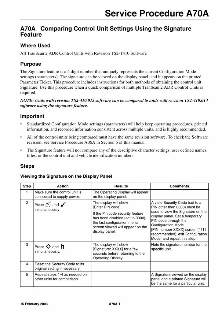
Service Procedure A70A
A70A Comparing Control Unit Settings Using the Signature Feature
Where UsedAll TranScan 2 ADR Control Units with Revision TS2-T410 Software
PurposeThe Signature feature is a 4 digit number that uniquely represents the current Configuration Mode settings (parameters). The signature can be viewed on the display panel, and it appears on the printed Parameter Ticket. This procedure includes instructions for both methods of obtaining the control unit Signature. Use this procedure when a quick comparison of multiple TranScan 2 ADR Control Units is required.
NOTE: Units with revision TS2-410.013 software can be compared to units with revision TS2-410.014 software using the signature feature.
Important• Standardized Configuration Mode settings (parameters) will help keep operating procedures, printed
information, and recorded information consistent across multiple units, and is highly recommended.
• All of the control units being compared must have the same revision software. To check the Software revision, see Service Procedure A06A in Section 6 of this manual.
• The Signature feature will not compare any of the descriptive character settings, user defined names, titles, or the control unit and vehicle identification numbers.
Steps
Viewing the Signature on the Display Panel
Step Action Results Comments
1 Make sure the control unit is connected to supply power.
The Operating Display will appear on the display panel.
2Press and simultaneously
The display will show [Enter PIN code].
If the Pin code security feature has been disabled (set to 0000), the last configuration menu screen viewed will appear on the display panel.
A valid Security Code (set to a PIN other than 0000) must be used to view the Signature on the display panel. Set a temporary PIN code through the Configuration Mode [PIN number XXXX] screen (1111 recommended), exit Configuration Mode, and repeat this step.
3Press and simultaneously.
The display will show [Signature: XXXX] for a few seconds before returning to the Operating Display.
Note the signature number for the specific unit.
4 Reset the Security Code to its original setting if necessary.
5 Repeat steps 1-4 as needed on other units for comparison.
A Signature viewed on the display panel and a printed Signature will be the same for a particular unit.
A70A-115 February 2003

Service Procedure A70A
Viewing the Signature by Printing a Parameter Ticket
Step Action Results Comments
1 Make sure the control unit is connected to supply power.
The Operating Display will appear on the display panel.
2 Make sure the control unit printer has an adequate supply of paper and printer ribbon.
3Press and simultaneously
The display will show [Enter PIN code].
NOTE: If the Pin code security feature has been disabled (set to 0000), the last configuration menu screen viewed will appear on the display panel.
A valid Security Code (set to a PIN other than 0000) must be used to print a Parameter Ticket. Set a temporary PIN code through the Configuration Mode [PIN number XXXX] screen (1111 recommended), exit Configuration Mode, and repeat this step.
4Press , , , to enter the Print Parameter Ticket code 1212.
The display panel will show [Print parameters] and the printer will begin printing the current configuration menu screen settings in order on a single Parameter Ticket.
When finished, the printer will stop and the Operating Display will appear on the display panel.
5 Reset the Security Code to its original setting if necessary.
6 The Signature appears on the last line of the Parameter Ticket as shown.
7 Repeat steps 1-5 as needed on other units for comparison.
A printed Signature and a Signature viewed on the display panel will be the same for a particular unit.
A70A-2 15 February 2003
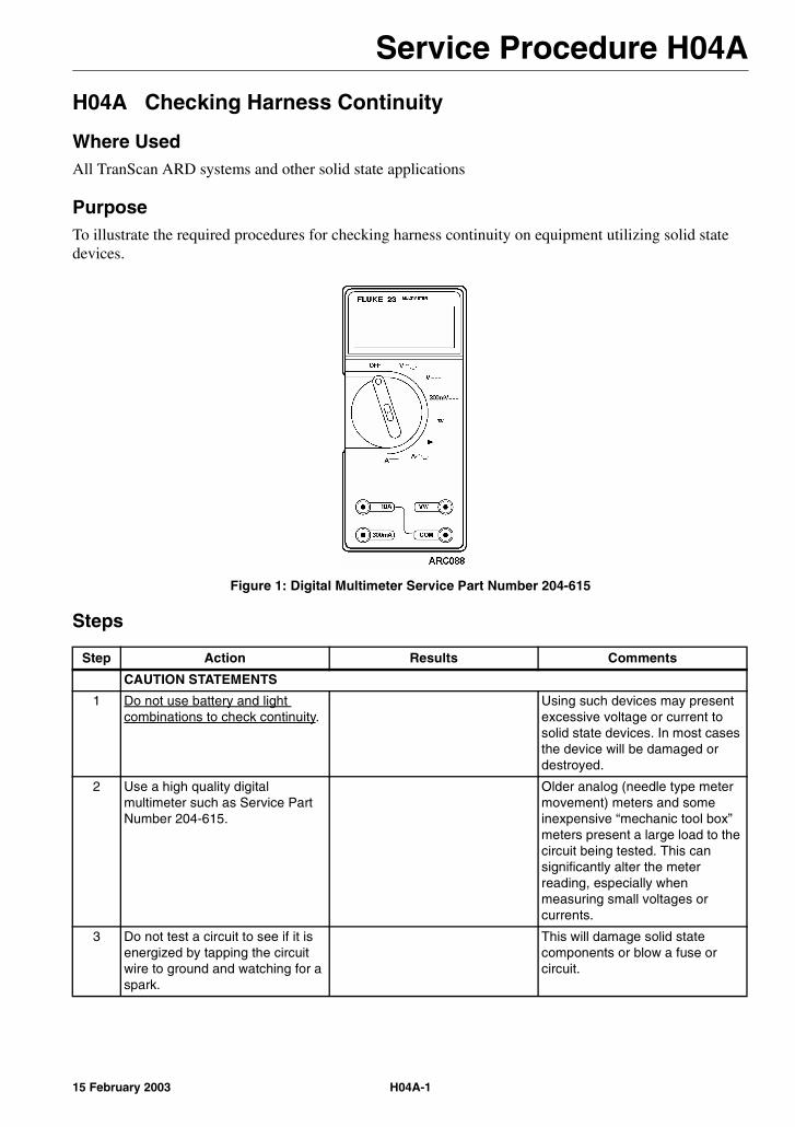
Service Procedure H04A
H04A Checking Harness Continuity
Where UsedAll TranScan ARD systems and other solid state applications
PurposeTo illustrate the required procedures for checking harness continuity on equipment utilizing solid state devices.
Figure 1: Digital Multimeter Service Part Number 204-615
Steps
Step Action Results Comments
CAUTION STATEMENTS
1 Do not use battery and light combinations to check continuity.
Using such devices may present excessive voltage or current to solid state devices. In most cases the device will be damaged or destroyed.
2 Use a high quality digital multimeter such as Service Part Number 204-615.
Older analog (needle type meter movement) meters and some inexpensive “mechanic tool box” meters present a large load to the circuit being tested. This can significantly alter the meter reading, especially when measuring small voltages or currents.
3 Do not test a circuit to see if it is energized by tapping the circuit wire to ground and watching for a spark.
This will damage solid state components or blow a fuse or circuit.
H04A-115 February 2003
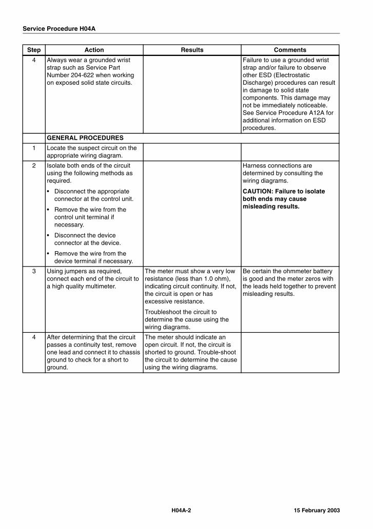
Service Procedure H04A
4 Always wear a grounded wrist strap such as Service Part Number 204-622 when working on exposed solid state circuits.
Failure to use a grounded wrist strap and/or failure to observe other ESD (Electrostatic Discharge) procedures can result in damage to solid state components. This damage may not be immediately noticeable. See Service Procedure A12A for additional information on ESD procedures.
GENERAL PROCEDURES
1 Locate the suspect circuit on the appropriate wiring diagram.
2 Isolate both ends of the circuit using the following methods as required.
• Disconnect the appropriate connector at the control unit.
• Remove the wire from the control unit terminal if necessary.
• Disconnect the device connector at the device.
• Remove the wire from the device terminal if necessary.
Harness connections are determined by consulting the wiring diagrams.
CAUTION: Failure to isolate both ends may cause misleading results.
3 Using jumpers as required, connect each end of the circuit to a high quality multimeter.
The meter must show a very low resistance (less than 1.0 ohm), indicating circuit continuity. If not, the circuit is open or has excessive resistance.
Troubleshoot the circuit to determine the cause using the wiring diagrams.
Be certain the ohmmeter battery is good and the meter zeros with the leads held together to prevent misleading results.
4 After determining that the circuit passes a continuity test, remove one lead and connect it to chassis ground to check for a short to ground.
The meter should indicate an open circuit. If not, the circuit is shorted to ground. Trouble-shoot the circuit to determine the cause using the wiring diagrams.
Step Action Results Comments
H04A-2 15 February 2003

Section 7Service InformationA16A Software (PROM Chip) Interchange and Service Parts NumbersA17A Replacement Hardware Service Part Numbers

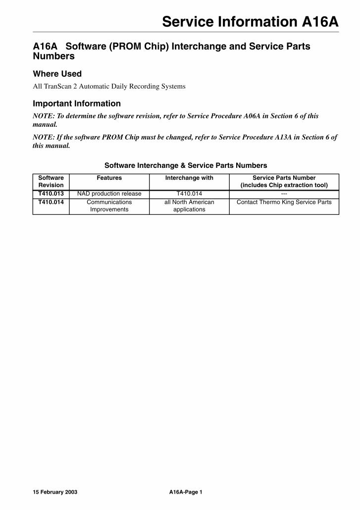
Service Information A16A
A16A Software (PROM Chip) Interchange and Service Parts Numbers
Where UsedAll TranScan 2 Automatic Daily Recording Systems
Important InformationNOTE: To determine the software revision, refer to Service Procedure A06A in Section 6 of this manual.
NOTE: If the software PROM Chip must be changed, refer to Service Procedure A13A in Section 6 of this manual.
Software Interchange & Service Parts Numbers
Software Revision
Features Interchange with Service Parts Number(includes Chip extraction tool)
T410.013 NAD production release T410.014 ---T410.014 Communications
Improvementsall North American
applicationsContact Thermo King Service Parts
A16A-Page 115 February 2003

Service Information A16A
A16A-Page 2 15 February 2003
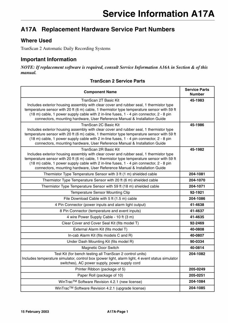
Service Information A17A
A17A Replacement Hardware Service Part Numbers
Where UsedTranScan 2 Automatic Daily Recording Systems
Important InformationNOTE: If replacement software is required, consult Service Information A16A in Section & of this manual.
TranScan 2 Service Parts
Component NameService Parts
Number
TranScan 2T Basic KitIncludes exterior housing assembly with clear cover and rubber seal, 1 thermistor type
temperature sensor with 20 ft (6 m) cable, 1 thermistor type temperature sensor with 59 ft (18 m) cable, 1 power supply cable with 2 in-line fuses, 1 - 4 pin connector, 2 - 8 pin
connectors, mounting hardware, User Reference Manual & Installation Guide
45-1983
TranScan 2C Basic KitIncludes exterior housing assembly with clear cover and rubber seal, 1 thermistor type
temperature sensor with 20 ft (6 m) cable, 1 thermistor type temperature sensor with 59 ft (18 m) cable, 1 power supply cable with 2 in-line fuses, 1 - 4 pin connector, 2 - 8 pin
connectors, mounting hardware, User Reference Manual & Installation Guide
45-1986
TranScan 2R Basic KitIncludes exterior housing assembly with clear cover and rubber seal, 1 thermistor type
temperature sensor with 20 ft (6 m) cable, 1 thermistor type temperature sensor with 59 ft (18 m) cable, 1 power supply cable with 2 in-line fuses, 1 - 4 pin connector, 2 - 8 pin
connectors, mounting hardware, User Reference Manual & Installation Guide
45-1982
Thermistor Type Temperature Sensor with 3 ft (1 m) shielded cable 204-1081
Thermistor Type Temperature Sensor with 20 ft (6 m) shielded cable 204-1070
Thermistor Type Temperature Sensor with 59 ft (18 m) shielded cable 204-1071
Temperature Sensor Mounting Clip 92-1921
File Download Cable with 5 ft (1.5 m) cable 204-1086
4 Pin Connector (power inputs and alarm light output) 41-4638
8 Pin Connector (temperature and event inputs) 41-4637
4 wire Power Supply Cable - 10 ft (3 m) 41-4635
Clear Cover and Cover Seal Kit (fits model T) 92-2469
External Alarm Kit (fits model T) 40-0808
In-cab Alarm Kit (fits models C and R) 40-0807
Under Dash Mounting Kit (fits model R) 90-0334
Magnetic Door Switch 40-0814
Test Kit (for bench testing all TranScan 2 control units)Includes temperature simulator, control box (power light, alarm light, 4 event status simulator
switches), AC power supply, power supply cord
204-1082
Printer Ribbon (package of 5) 205-0249
Paper Roll (package of 10) 205-0251
WinTracTM Software Revision 4.2.1 (new license) 204-1084
WinTracTM Software Revision 4.2.1 (upgrade license) 204-1085
A17A-Page 115 February 2003

Service Information A17A
A17A-Page 2 15 February 2003

Section 8Schematics and Wiring DiagramsDescription PageStandard Wiring Diagram (Without Temperature Out-of-Range Alarms) .................. 8 - 1Standard Wiring Diagram (With Temperature Out-of-Range Alarms) ....................... 8 - 2


Sch
ematics an
d W
iring
Diag
rams
15 Feb
ruary 2003
8-1
larms)
Standard Wiring Diagram (Without Temperature Out-of-Range A
Sch
ematics an
d W
iring
Diag
rams
8-215 F
ebru
ary 2003
Standard Wiring Diagram
(With Temperature Out-of-Range Alarms)
IndexAadjusting recording interval 4-7alarms
clearing 4-8description 3-1selecting settings
alarm set (name) 4-7auto 4-7no alarm 4-7
Bbattery
removal 1-1
Ccalender/clock
adjusting procedure, control unit keys - SP A05Aadjusting procedure, remote computer - SP A05B
Celsius temperature display 3-3checking software revision
procedure - SP A06Acleaning and maintenance 2-3clearing alarms 4-8configuration aids 3-1configuration mode
entering, operator keys 3-4entering, remote computer 3-6menu screen flowchart 3-20menu screens
A# name 3-13Added time 3-12Alarm enable 3-11Alarm on T# 3-15Alarm reverse 3-11Alarm set # 3-13Alarm wait 3-14Auto Clk Adj 3-19Baud rate 3-18Clk Protect 3-19Date 3-18Day Code 3-9DeIce switch 3-10DIce reverse 3-10Door reverse 3-10Door switch 3-9ENG Display 3-17Extend time 3-12Graph high (alarm set enabled) 3-14Graph high (alarm sets disabled) 3-12Graph low (alarm set enabled) 3-14Graph low (alarm sets disabled)3-12High alarm 3-14Log by Day 3-8Low alarm 3-14min/update 3-9mms/hour 3-9
PIN number 3-17Preset names 3-12Print De-Ice 3-16Print door 3-16Print Spare 3-16Print T# 3-15R standard 3-17Set clock 3-19Spare switch 3-10Spare symbol 3-11Spr name 3-11Spr reverse 3-11Start time 3-8Stop time 3-8T# AlarmSet1 3-15T# AlarmSet2 3-15T# AutoAlarm 3-16T# cal val 3-17T# name 3-13T# No Alarms 3-16Temperature# 3-13Title1 3-20Title2 3-20Unit I/D 3-18Vehicle 3-20
connectors see wiringcontrol panel 4-2control unit
cleaning and maintenance 2-3description 2-2digital display panel 2-2memory 2-2models 2-2operator keys 2-3printer 2-3recording existing settings procedure - SP A02Asetting model 3-3setup information sheet - SP A02Asetup procedure, control unit keys - SP A04Asetup procedure, remote computer - SP A04Bwiring connections 2-6wiring connectors 2-5
control unit environment specifications 2-7controller see control unit
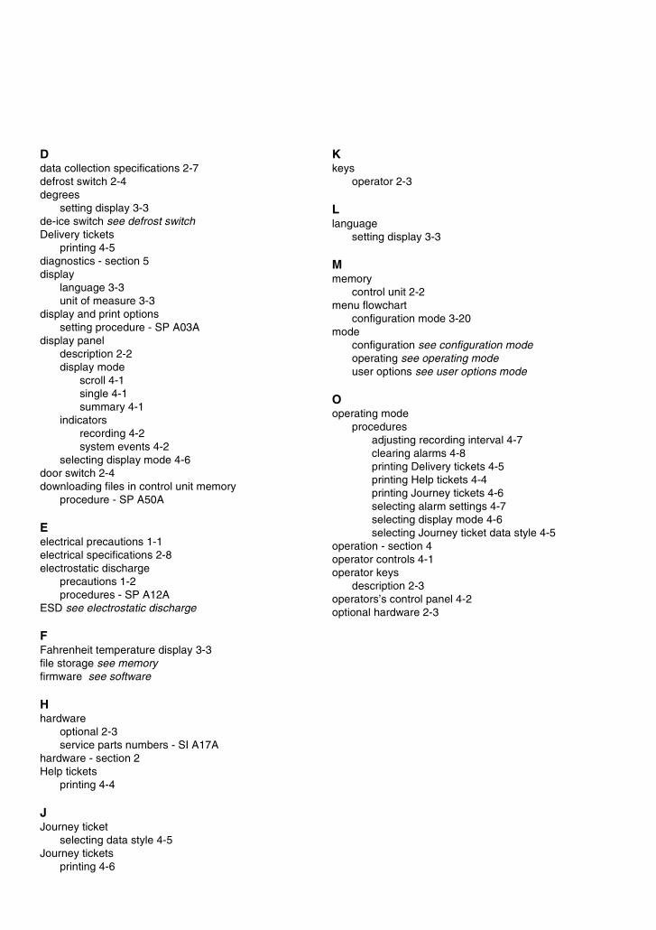
Ddata collection specifications 2-7defrost switch 2-4degrees
setting display 3-3de-ice switch see defrost switchDelivery tickets
printing 4-5diagnostics - section 5display
language 3-3unit of measure 3-3
display and print optionssetting procedure - SP A03A
display paneldescription 2-2display mode
scroll 4-1single 4-1summary 4-1
indicatorsrecording 4-2system events 4-2
selecting display mode 4-6door switch 2-4downloading files in control unit memory
procedure - SP A50A
Eelectrical precautions 1-1electrical specifications 2-8electrostatic discharge
precautions 1-2procedures - SP A12A
ESD see electrostatic discharge
FFahrenheit temperature display 3-3file storage see memoryfirmware see software
Hhardware
optional 2-3service parts numbers - SI A17A
hardware - section 2Help tickets
printing 4-4
JJourney ticket
selecting data style 4-5Journey tickets
printing 4-6
Kkeys
operator 2-3
Llanguage
setting display 3-3
Mmemory
control unit 2-2menu flowchart
configuration mode 3-20mode
configuration see configuration modeoperating see operating modeuser options see user options mode
Ooperating mode
proceduresadjusting recording interval 4-7clearing alarms 4-8printing Delivery tickets 4-5printing Help tickets 4-4printing Journey tickets 4-6selecting alarm settings 4-7selecting display mode 4-6selecting Journey ticket data style 4-5
operation - section 4operator controls 4-1operator keys
description 2-3operators’s control panel 4-2optional hardware 2-3
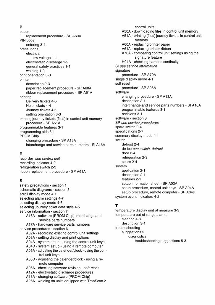
Ppaper
replacement procedure - SP A60APIN code
entering 3-4precautions
electricallow voltage 1-1
electrostatic discharge 1-2general safety practices 1-1welding 1-2
print orientation 3-3printer
description 2-3paper replacement procedure - SP A60Aribbon replacement procedure - SP A61A
printingDelivery tickets 4-5Help tickets 4-4Journey tickets 4-6setting orientation 3-3
printing journey tickets (files) in control unit memoryprocedure - SP A51A
programmable features 3-1programming aids 3-1PROM Chip
changing procedure - SP A13Ainterchange and service parts numbers - SI A16A
Rrecorder see control unitrecording indicator 4-2refrigeration switch 2-3ribbon replacement procedure - SP A61A
Ssafety precautions - section 1schematic diagrams - section 8scroll display mode 4-1selecting alarm settings 4-7selecting display mode 4-6selecting Journey ticket data style 4-5service information - section 7
A16A - software (PROM Chip) interchange and service parts numbers
A17A - hardware service parts numbersservice procedures - section 6
A02A - recording existing control unit settingsA03A - setting display and print optionsA04A - system setup - using the control unit keysA04B - system setup - using a remote computerA05A - adjusting the calender/clock - using the con-
trol unit keysA05B - adjusting the calender/clock - using a re-
mote computerA06A - checking software revision - soft resetA12A - electrostatic discharge proceduresA13A - changing software (PROM Chip)A26A - welding on units equipped with TranScan 2
control unitsA50A - downloading files in control unit memoryA51A - printing (files) journey tickets in control unit
memoryA60A - replacing printer paperA61A - replacing printer ribbonA70A - comparing control unit settings using the
signature featureH04A - checking harness continuity
SI see service informationsignature
procedure - SP A70Asingle display mode 4-1soft reset
procedure - SP A06Asoftware
changing procedure - SP A13Adescription 3-1interchange and service parts numbers - SI A16Aprogrammable features 3-1revisions 3-1
software - section 3SP see service proceduresspare switch 2-4specifications 2-7summary display mode 4-1switch
defrost 2-4de-ice see switch, defrostdoor 2-4refrigeration 2-3spare 2-4
systemapplication 2-1description 2-1features 2-1setup information sheet - SP A02Asetup procedure, control unit keys - SP A04Asetup procedure, remote computer - SP A04B
system event indicators 4-2
Ttemperature display unit of measure 3-3temperature out-of-range alarms
clearing 4-8description 3-1
troubleshootingsuggestions 5
diagnosticstroubleshooting suggestions 5-3
Uunit of measure
setting display 3-3user options mode
control unit model 3-3display language 3-3display unit of measure 3-3print orientation 3-3unit of measure 3-3
Wwelding
precautions 1-2procedures - SP A26A
wiringchecking harness continuity - SP H04Acontrol unit connections 2-6diagrams - section 8power and lighting (4 pin) connector 2-5serial port (3 pin) connector 2-5temperature and event (8 pin) connector 2-5

Changes and Comments
You are invited to comment on this manual so it can be updated and improved to better meet your needs. Any corrections or comments are welcome. Please complete the following information:
Manual Name: _____________________________________________________________________
Page Number(s): ___________________________________________________________________
Your Name:________________________________________________________________________
Company Name: ___________________________________________________________________
Phone Number: ____________________________________________________________________
Corrections and Comments: _________________________________________________________
__________________________________________________________________________________
__________________________________________________________________________________
__________________________________________________________________________________
__________________________________________________________________________________
__________________________________________________________________________________
__________________________________________________________________________________
__________________________________________________________________________________
__________________________________________________________________________________
__________________________________________________________________________________
__________________________________________________________________________________
__________________________________________________________________________________
__________________________________________________________________________________
Return Form To: Thermo King Corporation314 West 90th StreetMail Stop 38Bloomington, MN 55420Attn: TranScan 2 Product Manager
