transducers/btl7-aceg... · english 5 1.1 validity this guide describes the construction, function...
TRANSCRIPT

User's Guide
BTL7-A/C/E/G5 _ _ -M _ _ _ _ -H/W(8)-S32/S115/KA _ _/K _ _
S32
english

www.balluff.com
www.balluff.com 3english
BTL7-A/C/E/G5 _ _ -M _ _ _ _ -H/W(8)-S32/S115/KA _ _/K_ _Micropulse Transducer - Rod Style
Notes to the user 1 5
Validity 1.1 5Symbols and conventions 1.2 5Scope of delivery 1.3 5Approvals and markings 1.4 5
Safety 2 6
Intended use 2.1 6General safety notes for the position measuring system 2.2 6Meaning of the warnings 2.3 6Disposal 2.4 6
Construction and function 3 7
Construction 3.1 7Function 3.2 7
Installation and connection 4 8
Installation guidelines 4.1 8Preparing for installation 4.2 8Installing the transducer 4.3 9
Installation recommendation for hydraulic cylinders 4.3.1 9Electrical connection 14.4 0
Connector S32 14.4.1 0Connector S115 14.4.2 0Cable connection KA_ _/K_ _ 14.4.3 1
Shielding and cable routing 14.5 1
Startup 15 2
Starting up the system 15.1 2Operating notes 15.2 2
Calibration procedure 16 3
Programming inputs 16.1 3Calibration procedure notes 16.2 3Calibration procedure overview 16.3 4
Teach-in 16.3.1 4Inverting (only for BTL7-C/E) 16.3.2 4Reset 16.3.3 4
Teach-in 17 5
Inverting 18 6
Resetting all values (reset) 19 7
Technical data 110 8
Accuracy 110.1 8Ambient conditions 110.2 8Supply voltage (external) 110.3 8Output 110.4 8Input 110.5 8Dimensions, weights 110.6 9
4 english
BTL7-A/C/E/G5 _ _ -M _ _ _ _ -H/W(8)-S32/S115/KA _ _/K _ _Micropulse Transducer - Rod Style
Accessories 211 0
Magnets 211.1 0Mounting nut 211.2 0Connectors and cables 211.3 1
BKS-S32/S33M-00, freely configurable 211.3.1 1BKS-S232/S233-PU-_ _, preassembled 211.3.2 1BKS-S115/S116-PU-_ _, preassembled 211.3.3 2
Calibration box 211.4 2
Type code breakdown 212 3
Appendix 213 4
Converting units of length 213.1 4Part label 213.2 4
www.balluff.com 5english
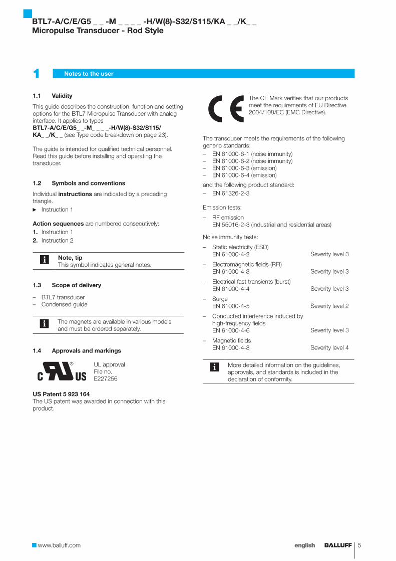
Validity1.1
This guide describes the construction, function and setting options for the BTL7 Micropulse Transducer with analog interface. It applies to types BTL7-A/C/E/G5_ _-M_ _ _ _-H/W(8)-S32/S115/ KA_ _/K_ _ (see Type code breakdown on page 23).
The guide is intended for qualified technical personnel. Read this guide before installing and operating the transducer.
Symbols and conventions1.2
Individual instructions are indicated by a preceding triangle.
Instruction 1 ►
Action sequences are numbered consecutively:Instruction 11. Instruction 22.
Note, tipThis symbol indicates general notes.
Scope of delivery1.3
BTL7 transducer –Condensed guide –
The magnets are available in various models and must be ordered separately.
Approvals and markings1.4
UL approvalFile no.E227256
US Patent 5 923 164The US patent was awarded in connection with this product.
The CE Mark verifies that our products meet the requirements of EU Directive 2004/108/EC (EMC Directive).
The transducer meets the requirements of the following generic standards:
EN 61000-6-1 (noise immunity) –EN 61000-6-2 (noise immunity) –EN 61000-6-3 (emission) –EN 61000-6-4 (emission) –
and the following product standard:EN 61326-2-3 –
Emission tests:
RF emission –EN 55016-2-3 (industrial and residential areas)
Noise immunity tests:
Static electricity (ESD) –EN 61000-4-2 Severity level 3
Electromagnetic fields (RFI) –EN 61000-4-3 Severity level 3
Electrical fast transients (burst) –EN 61000-4-4 Severity level 3
Surge –EN 61000-4-5 Severity level 2
Conducted interference induced by –high-frequency fields EN 61000-4-6 Severity level 3
Magnetic fields –EN 61000-4-8 Severity level 4
More detailed information on the guidelines, approvals, and standards is included in the declaration of conformity.
Notes to the user1
BTL7-A/C/E/G5 _ _ -M _ _ _ _ -H/W(8)-S32/S115/KA _ _/K_ _Micropulse Transducer - Rod Style
6 english
Intended use2.1
The BTL7 Micropulse Transducer, together with a machine controller (e.g. PLC), comprises a position measuring system. It is intended to be installed into a machine or system. Flawless function in accordance with the specifications in the technical data is ensured only when using original BALLUFF accessories. Use of any other components will void the warranty.
Opening the transducer or non-approved use are not permitted and will result in the loss of warranty and liability claims against the manufacturer.
General safety notes for the position 2.2 measuring system
Installation and startup may only be performed by trained specialists with basic electrical knowledge.Specialists are those who can recognize possible hazards and institute the appropriate safety measures due to their professional training, knowledge, and experience, as well as their understanding of the relevant regulations pertaining to the work to be done.
The operator is responsible for ensuring that local safety regulations are observed.In particular, the operator must take steps to ensure that a defect in the position measuring system will not result in hazards to persons or equipment.If defects and unresolvable faults occur in the transducer, it should be taken out of service and secured against unauthorized use.
Meaning of the warnings2.3
Always observe the warnings in these instructions and the measures described to avoid hazards.
The warnings used here contain various signal words and are structured as follows:
SIGNAL WORDHazard type and sourceConsequences if not complied with
Measures to avoid hazards f
The individual signal words mean:
NOTICE!Identifies a hazard that could damage or destroy the product.
DANGERThe general warning symbol in conjunction with the signal word DANGER identifies a hazard which, if not avoided, will certainly result in death or serious injury.
Disposal2.4
Observe the national regulations for disposal. ►
Safety2
BTL7-A/C/E/G5 _ _ -M _ _ _ _ -H/W(8)-S32/S115/KA _ _/K _ _Micropulse Transducer - Rod Style

www.balluff.com 7english
4312
20
20
Ø D
1
60
25
G
Ø 65
10
10
60
0.5 Ø 25
10max. 723
35
0.5 Ø 25
3120
Fig. 3-1: BTL7...H/W(8)... transducer, construction and function
Construction3.1
Electrical connection: The electrical connection is made via a cable or a connector (see Type code breakdown on page 23).
BTL housing: Housing containing the processing electronics.
Mounting thread: The transducers with Ø 10.2 mm have an additional thread at the end of the rod to support larger nominal lengths. We recommend assembling this transducer on the fastening screw thread:
BTL7-…-H: M18×1.5 –BTL7-…-W: 3/4”-16UNF –
Magnet: Defines the position to be measured on the waveguide. Magnets are available in various models and must be ordered separately (see Accessories on page 20).
Nominal length: Defines the available measuring range. Rods with various nominal lengths from 25 mm to 7620 mm are available depending on the version:
Ø 10.2 mm: Nominal length from 25 mm to 7620 mm –Ø 8 mm: Nominal length from 25 mm to 1016 mm –
Damping zone: Area at the end of the rod that cannot be used for measurements, but which may be passed over.
Construction and function3
BTL7...-S32Axial
BTL7...-S115Axial
BTL7...-K_ _Radial
Mounting surface
1) Unusable area
2) Not included in scope of delivery
3) Ø 5 for hook spanner Ø 65, max. tightening torque 100 Nm
Damping zone
Magnets1)
Nominal length =
Measuring range
2)
1)
BTL7...-KA_ _Axial
Version D1 G
...-H/W-... 10.2 mm Thread M4x4/6 deep
...-H8/W8-... 8 mm No thread
3)
Function3.2
The Micropulse Transducer contains the waveguide which is protected by an outer stainless steel tube (rod). A magnet is moved along the waveguide. This magnet is connected to the system part whose position is to be determined.
The magnet defines the position to be measured on the waveguide.
An internally generated INIT pulse interacts with the magnetic field of the magnet to generate a torsional wave in the waveguide which propagates at ultrasonic speed.
The component of the torsional wave which arrives at the end of the waveguide is absorbed in the damping zone to prevent reflection. The component of the torsional wave which arrives at the beginning of the waveguide is converted by a coil into an electrical signal. The travel time of the wave is used to calculate the position. Depending on the version, this information is made available as a voltage or current output with a rising or falling gradient.
Thread size:H: M18×1.5W: 3/4”-16UNF
H: 40-1 mmW: 2”-0.04”
BTL7-A/C/E/G5 _ _ -M _ _ _ _ -H/W(8)-S32/S115/KA _ _/K_ _Micropulse Transducer - Rod Style
8 english
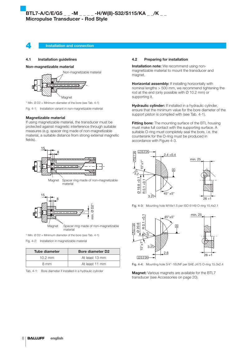
Installation guidelines4.1
Non-magnetizable material
Magnet
Non-magnetizable material
1) Min. Ø D2 = Minimum diameter of the bore (see Tab. 4-1)
Installation variant in non-magnetizable materialFig. 4-1:
Magnetizable materialIf using magnetizable material, the transducer must be protected against magnetic interference through suitable measures (e.g. spacer ring made of non-magnetizable material, a suitable distance from strong external magnetic fields).
Spacer ring made of non-magnetizable material
Magnet
min
.Ø D
21)
Spacer ring made of non-magnetizable material
Magnet
1) Min. Ø D2 = Minimum diameter of the bore (see Tab. 4-1)
Installation in magnetizable materialFig. 4-2:
Tube diameter Bore diameter D2
10.2 mm At least 13 mm
8 mm At least 11 mm
Bore diameter if installed in a hydraulic cylinderTab. 4-1:
Preparing for installation4.2
Installation note: We recommend using non-magnetizable material to mount the transducer and magnet.
Horizontal assembly: If installing horizontally with nominal lengths > 500 mm, we recommend tightening the rod at the end (only possible with Ø 10.2 mm) or supporting it.
Hydraulic cylinder: If installed in a hydraulic cylinder, ensure that the minimum value for the bore diameter of the support piston is complied with (see Tab. 4-1).
Fitting bore: The mounting surface of the BTL housing must make full contact with the supporting surface. A suitable O-ring must completely seal the bore, i.e. the countersink for the O-ring must be produced in accordance with Figure 4-3.
Fig. 4-3: Mounting hole M18x1.5 per ISO 6149 O-ring 15.4x2.1
Fig. 4-4: Mounting hole 3/4”-16UNF per SAE J475 O-ring 15.3x2.4
Magnet: Various magnets are available for the BTL7 transducer (see Accessories on page 20).
Installation and connection4
BTL7-A/C/E/G5 _ _ -M _ _ _ _ -H/W(8)-S32/S115/KA _ _/K _ _Micropulse Transducer - Rod Style
www.balluff.com 9english
Installing the transducer4.3
NOTICE!Interference in functionImproper installation can compromise the function of the transducer and result in increased wear.
The mounting surface of the transducer must make ffull contact with the supporting surface.The bore must be perfectly sealed (O-ring/flat seal). f
Make a mounting hole with thread (possibly with ►countersink for the O-ring) acc. to Fig. 4-3 or Fig. 4-4.Screw the transducer with mounting thread into the ►mounting hole (max. torque 100 Nm).
Radial cable outlet (BTL7...-K_ _)During installation, the direction of the cable outlet is determined by the thread.
Install the magnet (accessories). ►For nominal lengths > 500 mm: Tighten the rod at the ►end (only possible with Ø 10.2 mm) or support it.
Suitable nuts for the mounting thread are available as accessories (see page 20).
Installation recommendation for hydraulic 4.3.1 cylinders
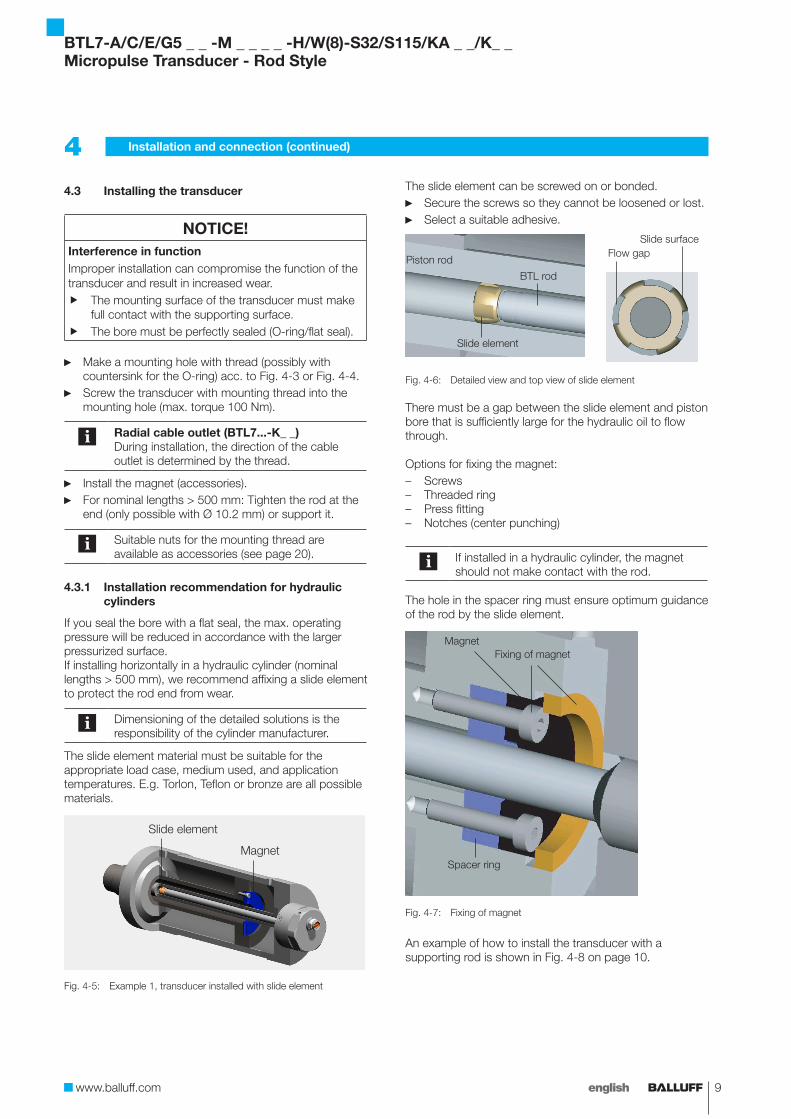
If you seal the bore with a flat seal, the max. operating pressure will be reduced in accordance with the larger pressurized surface.If installing horizontally in a hydraulic cylinder (nominal lengths > 500 mm), we recommend affixing a slide element to protect the rod end from wear.
Dimensioning of the detailed solutions is the responsibility of the cylinder manufacturer.
The slide element material must be suitable for the appropriate load case, medium used, and application temperatures. E.g. Torlon, Teflon or bronze are all possible materials.
Slide element
Magnet
Fig. 4-5: Example 1, transducer installed with slide element
The slide element can be screwed on or bonded.Secure the screws so they cannot be loosened or lost. ►Select a suitable adhesive. ►
Slide element
BTL rod
Piston rod
Slide surfaceFlow gap
Detailed view and top view of slide elementFig. 4-6:
There must be a gap between the slide element and piston bore that is sufficiently large for the hydraulic oil to flow through.
Options for fixing the magnet:Screws –Threaded ring –Press fitting –Notches (center punching) –
If installed in a hydraulic cylinder, the magnet should not make contact with the rod.
The hole in the spacer ring must ensure optimum guidance of the rod by the slide element.
Spacer ring
MagnetFixing of magnet
Fig. 4-7: Fixing of magnet
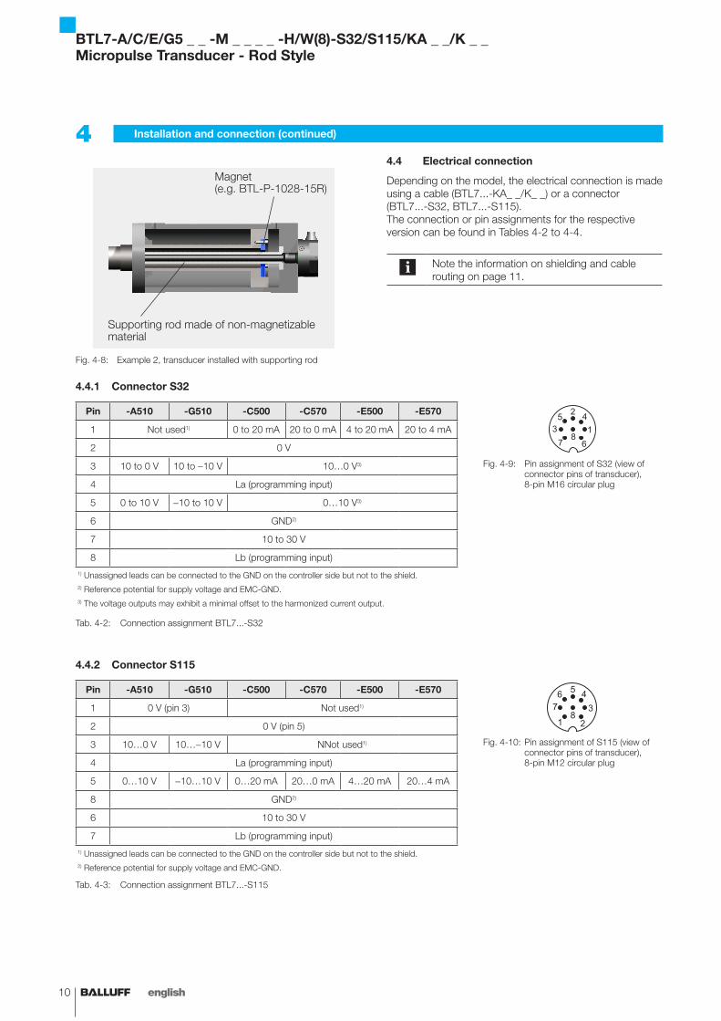
An example of how to install the transducer with a supporting rod is shown in Fig. 4-8 on page 10.
4 Installation and connection (continued)
BTL7-A/C/E/G5 _ _ -M _ _ _ _ -H/W(8)-S32/S115/KA _ _/K_ _Micropulse Transducer - Rod Style
10 english
Magnet(e.g. BTL-P-1028-15R)
Supporting rod made of non-magnetizable material
Fig. 4-8: Example 2, transducer installed with supporting rod
Electrical connection4.4
Depending on the model, the electrical connection is made using a cable (BTL7...-KA_ _/K_ _) or a connector (BTL7...-S32, BTL7...-S115).The connection or pin assignments for the respective version can be found in Tables 4-2 to 4-4.
Note the information on shielding and cable routing on page 11.
4 Installation and connection (continued)
Connector S324.4.1
Pin -A510 -G510 -C500 -C570 -E500 -E570
Pin assignment of S32 (view of Fig. 4-9: connector pins of transducer), 8-pin M16 circular plug
1 Not used1) 0 to 20 mA 20 to 0 mA 4 to 20 mA 20 to 4 mA
2 0 V
3 10 to 0 V 10 to -10 V 10…0 V3)
4 La (programming input)
5 0 to 10 V -10 to 10 V 0…10 V3)
6 GND2)
7 10 to 30 V
8 Lb (programming input)
1) Unassigned leads can be connected to the GND on the controller side but not to the shield.2) Reference potential for supply voltage and EMC-GND.3) The voltage outputs may exhibit a minimal offset to the harmonized current output.
Connection assignment BTL7...-S32Tab. 4-2:
Connector S1154.4.2
Pin -A510 -G510 -C500 -C570 -E500 -E570
Pin assignment of S115 (view of Fig. 4-10: connector pins of transducer), 8-pin M12 circular plug
1 0 V (pin 3) Not used1)
2 0 V (pin 5)
3 10…0 V 10…-10 V NNot used1)
4 La (programming input)
5 0…10 V -10…10 V 0…20 mA 20…0 mA 4…20 mA 20…4 mA
8 GND2)
6 10 to 30 V
7 Lb (programming input)
1) Unassigned leads can be connected to the GND on the controller side but not to the shield.2) Reference potential for supply voltage and EMC-GND.
Connection assignment BTL7...-S115Tab. 4-3:
BTL7-A/C/E/G5 _ _ -M _ _ _ _ -H/W(8)-S32/S115/KA _ _/K _ _Micropulse Transducer - Rod Style
www.balluff.com 11english
Cable connection KA_ _/K_ _4.4.3
Cable color -A510 -G510 -C500 -C570 -E500 -E570
YE yellow Not used1) 0 to 20 mA 20 to 0 mA 4 to 20 mA 20 to 4 mA
GY gray 0 V
PK pink 10 to 0 V 10 to -10 V 10…0 V3)
RD red La (programming input)
GN green 0 to 10 V -10 to 10 V 0…10 V3)
BU blue GND2)
BN brown 10 to 30 V
WH white Lb (programming input)
1) Unassigned leads can be connected to the GND on the controller side but not to the shield.2) Reference potential for supply voltage and EMC-GND.3) The voltage outputs may exhibit a minimal offset to the harmonized current output.
Connection assignment BTL7...-KA_ _/K_ _Tab. 4-4:
Shielding and cable routing4.5
Defined ground!The transducer and the control cabinet must be at the same ground potential.
ShieldingTo ensure electromagnetic compatibility (EMC), observe the following:
Connect transducer and controller using a shielded –cable. Shield: Braided copper shield with minimum 85%.Connector version: Shield is internally connected to –connector housing.Cable version: On the transducer side, the cable –shielding is connected to the housing. Ground the cable shielding on the controller side (connect with the protective earth conductor).
Magnetic fieldsThe position measuring system is a magnetostrictive system. It is important to maintain adequate distance between the transducer cylinder and strong, external magnetic fields.
Cable routingDo not route the cable between the transducer, controller, and power supply near high voltage cables (inductive stray noise is possible).The cable must be routed tension-free.
Bending radius for fixed cableThe bending radius for a fixed cable must be at least five times the cable diameter.
4 Installation and connection (continued)
Cable length
BTL7-A/G Max. 30 m1)
BTL7-C/E Max. 100 m1)
1) Prerequisite: Construction, shielding and routing preclude the effect of any
external noise fields.
Cable lengths BTL7Tab. 4-5:
BTL7-A/C/E/G5 _ _ -M _ _ _ _ -H/W(8)-S32/S115/KA _ _/K_ _Micropulse Transducer - Rod Style

12 english
Startup5
Starting up the system5.1
DANGERUncontrolled system movementWhen starting up, if the position measuring system is part of a closed loop system whose parameters have not yet been set, the system may perform uncontrolled movements. This could result in personal injury and equipment damage.
Persons must keep away from the system's fhazardous zones.Startup must be performed only by trained technical fpersonnel.Observe the safety instructions of the equipment or fsystem manufacturer.
Check connections for tightness and correct polarity. 1. Replace damaged connections.Turn on the system.2. Check measured values and adjustable parameters 3. and readjust the transducer, if necessary.
Check for the correct values at the null point and end point, especially after replacing the transducer or after repair by the manufacturer.
Operating notes5.2
Check the function of the transducer and all associated –components on a regular basis.Take the position measuring system out of operation –whenever there is a malfunction.Secure the system against unauthorized use. –
BTL7-A/C/E/G5 _ _ -M _ _ _ _ -H/W(8)-S32/S115/KA _ _/K _ _Micropulse Transducer - Rod Style
www.balluff.com 13english
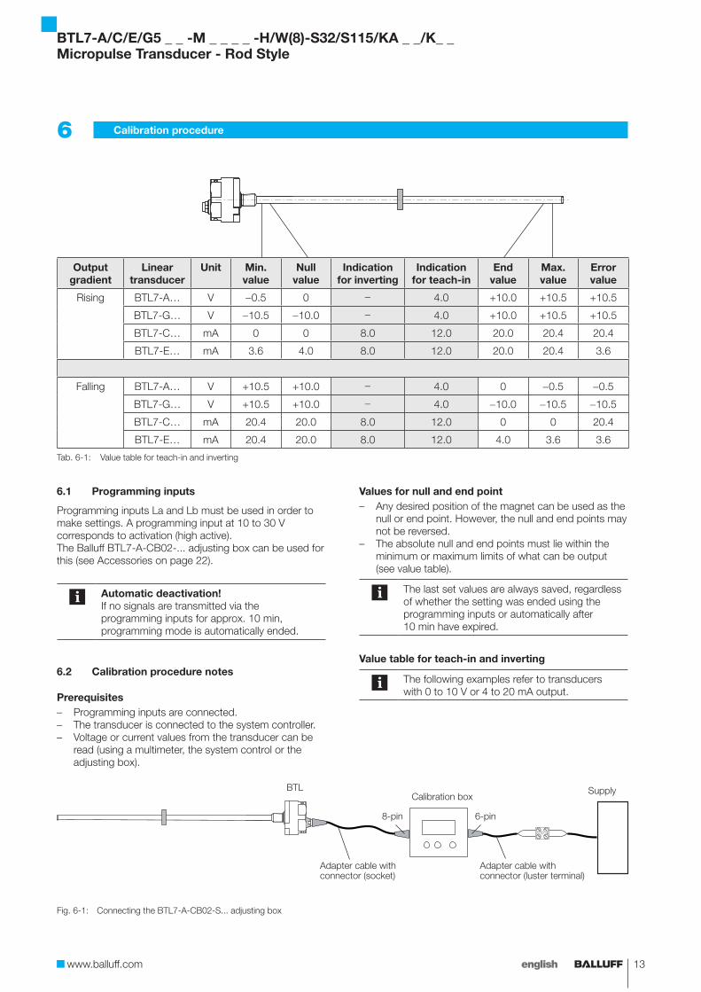
Output gradient
Linear transducer
Unit Min. value
Null value
Indication for inverting
Indication for teach-in
End value
Max. value
Error value
Rising BTL7-A… V -0.5 0 - 4.0 +10.0 +10.5 +10.5
BTL7-G… V -10.5 -10.0 - 4.0 +10.0 +10.5 +10.5
BTL7-C… mA 0 0 8.0 12.0 20.0 20.4 20.4
BTL7-E… mA 3.6 4.0 8.0 12.0 20.0 20.4 3.6
Falling BTL7-A… V +10.5 +10.0 - 4.0 0 -0.5 -0.5
BTL7-G… V +10.5 +10.0 - 4.0 -10.0 -10.5 -10.5
BTL7-C… mA 20.4 20.0 8.0 12.0 0 0 20.4
BTL7-E… mA 20.4 20.0 8.0 12.0 4.0 3.6 3.6
Value table for teach-in and invertingTab. 6-1:
Programming inputs6.1
Programming inputs La and Lb must be used in order to make settings. A programming input at 10 to 30 V corresponds to activation (high active).The Balluff BTL7-A-CB02-... adjusting box can be used for this (see Accessories on page 22).
Automatic deactivation!If no signals are transmitted via the programming inputs for approx. 10 min, programming mode is automatically ended.
Calibration procedure notes6.2
PrerequisitesProgramming inputs are connected. –The transducer is connected to the system controller. –Voltage or current values from the transducer can be –read (using a multimeter, the system control or the adjusting box).
Connecting the BTL7-A-CB02-S... adjusting boxFig. 6-1:
Calibration procedure6
Values for null and end pointAny desired position of the magnet can be used as the –null or end point. However, the null and end points may not be reversed.The absolute null and end points must lie within the –minimum or maximum limits of what can be output (see value table).
The last set values are always saved, regardless of whether the setting was ended using the programming inputs or automatically after 10 min have expired.
Value table for teach-in and inverting
The following examples refer to transducers with 0 to 10 V or 4 to 20 mA output.
BTLCalibration box
Supply
Adapter cable with connector (socket)
Adapter cable with connector (luster terminal)
6-pin8-pin
BTL7-A/C/E/G5 _ _ -M _ _ _ _ -H/W(8)-S32/S115/KA _ _/K_ _Micropulse Transducer - Rod Style
14 english
Calibration procedure overview6.3
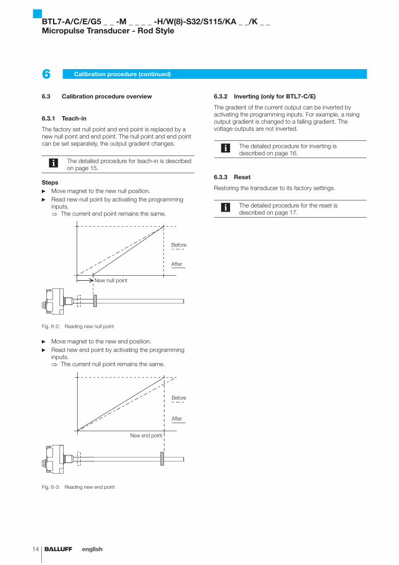
Teach-in6.3.1
The factory set null point and end point is replaced by a new null point and end point. The null point and end point can be set separately, the output gradient changes.
The detailed procedure for teach-in is described on page 15.
StepsMove magnet to the new null position. ►Read new null point by activating the programming ►inputs.
The current end point remains the same. ⇒
New null point
Before
After
Reading new null pointFig. 6-2:
Move magnet to the new end position. ►Read new end point by activating the programming ►inputs.
The current null point remains the same. ⇒
New end point
Before
After
Reading new end pointFig. 6-3:
6 Calibration procedure (continued)
Inverting (only for BTL7-C/E)6.3.2
The gradient of the current output can be inverted by activating the programming inputs. For example, a rising output gradient is changed to a falling gradient. The voltage outputs are not inverted.
The detailed procedure for inverting is described on page 16.
Reset6.3.3
Restoring the transducer to its factory settings.
The detailed procedure for the reset is described on page 17.
BTL7-A/C/E/G5 _ _ -M _ _ _ _ -H/W(8)-S32/S115/KA _ _/K _ _Micropulse Transducer - Rod Style
www.balluff.com 15english
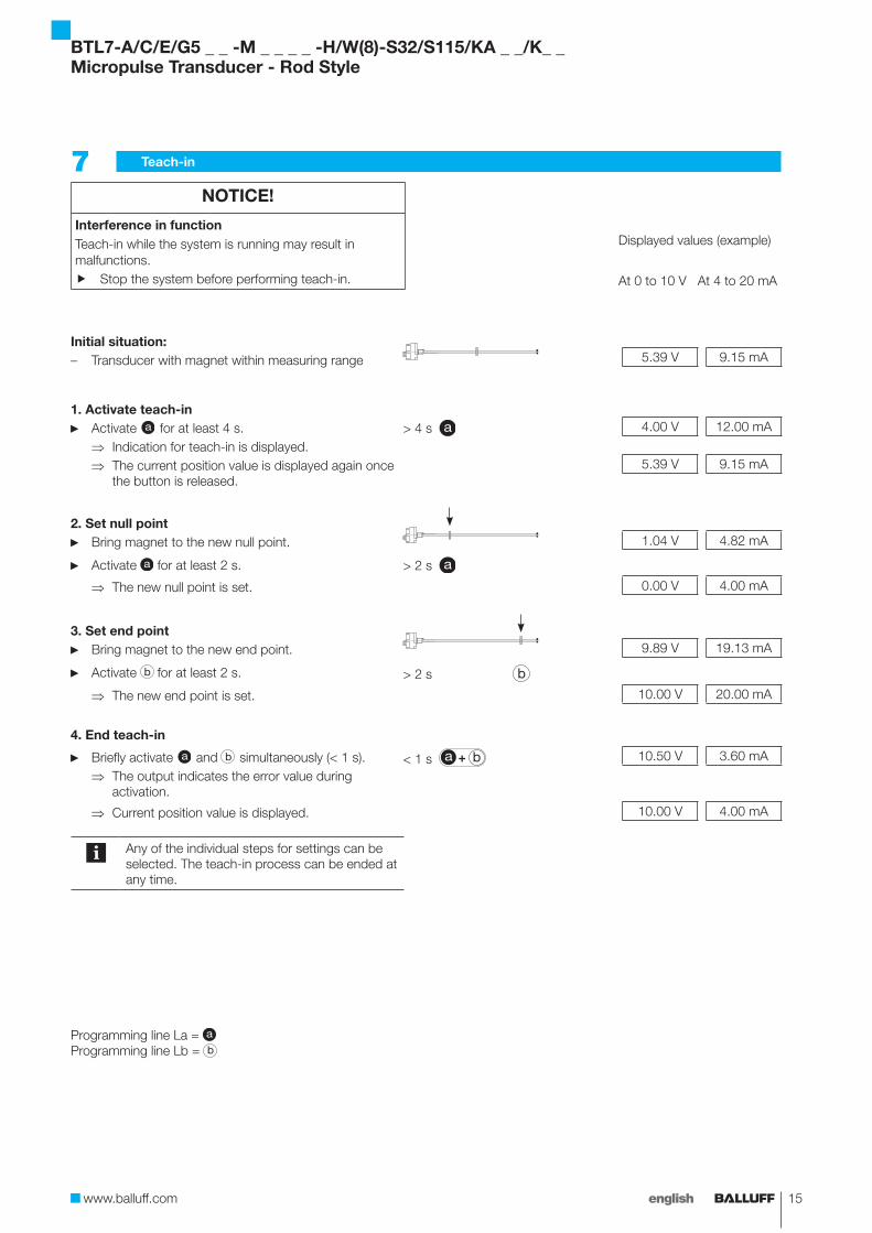
Teach-in7 NOTICE!
Interference in functionTeach-in while the system is running may result in malfunctions.
Stop the system before performing teach-in. f
Displayed values (example)
At 0 to 10 V At 4 to 20 mA
Initial situation:Transducer with magnet within measuring range – 5.39 V 9.15 mA
1. Activate teach-inActivate ► a for at least 4 s. > 4 s a 4.00 V 12.00 mA
Indication for teach-in is displayed. ⇒The current position value is displayed again once ⇒the button is released.
5.39 V 9.15 mA
2. Set null pointBring magnet to the new null point. ► 1.04 V 4.82 mA
Activate ► a for at least 2 s. > 2 s a
The new null point is set. ⇒ 0.00 V 4.00 mA
3. Set end pointBring magnet to the new end point. ► 9.89 V 19.13 mA
Activate ► b for at least 2 s. > 2 s b
The new end point is set. ⇒ 10.00 V 20.00 mA
4. End teach-in
Briefly activate ► a and b simultaneously (< 1 s). < 1 s a b 10.50 V 3.60 mA
The output indicates the error value during ⇒activation.
Current position value is displayed. ⇒ 10.00 V 4.00 mA
Any of the individual steps for settings can be selected. The teach-in process can be ended at any time.
Programming line La = a
Programming line Lb = b
BTL7-A/C/E/G5 _ _ -M _ _ _ _ -H/W(8)-S32/S115/KA _ _/K_ _Micropulse Transducer - Rod Style
16 english
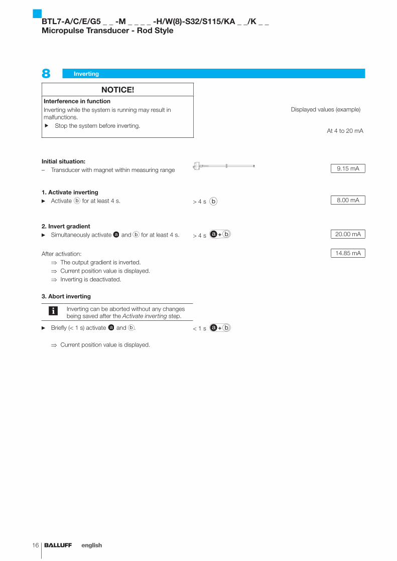
Inverting8 NOTICE!
Interference in functionInverting while the system is running may result in malfunctions.
Stop the system before inverting. f
Displayed values (example)
At 4 to 20 mA
Initial situation:Transducer with magnet within measuring range – 9.15 mA
1. Activate invertingActivate ► b for at least 4 s. > 4 s b 8.00 mA
2. Invert gradientSimultaneously activate ► a and b for at least 4 s. > 4 s a b 20.00 mA
After activation: 14.85 mA
The output gradient is inverted. ⇒Current position value is displayed. ⇒Inverting is deactivated. ⇒
3. Abort inverting
Inverting can be aborted without any changes being saved after the Activate inverting step.
Briefly (< 1 s) activate ► a and b . < 1 s a b
Current position value is displayed. ⇒
BTL7-A/C/E/G5 _ _ -M _ _ _ _ -H/W(8)-S32/S115/KA _ _/K _ _Micropulse Transducer - Rod Style
www.balluff.com 17english
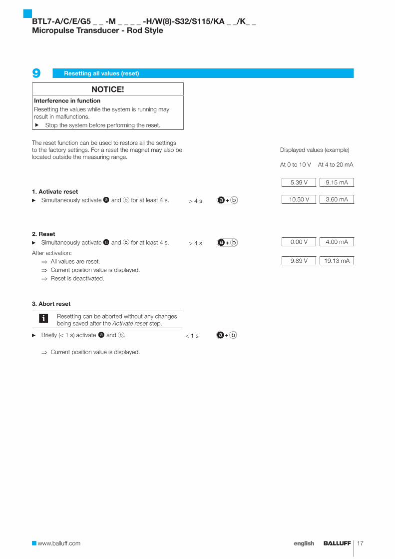
Resetting all values (reset)9 NOTICE!
Interference in functionResetting the values while the system is running may result in malfunctions.
Stop the system before performing the reset. f
The reset function can be used to restore all the settings to the factory settings. For a reset the magnet may also be located outside the measuring range.
Displayed values (example)
At 0 to 10 V At 4 to 20 mA
5.39 V 9.15 mA
1. Activate resetSimultaneously activate ► a and b for at least 4 s. > 4 s a b 10.50 V 3.60 mA
2. ResetSimultaneously activate ► a and b for at least 4 s. > 4 s a b 0.00 V 4.00 mA
After activation:All values are reset. ⇒ 9.89 V 19.13 mA
Current position value is displayed. ⇒Reset is deactivated. ⇒
3. Abort reset
Resetting can be aborted without any changes being saved after the Activate reset step.
Briefly (< 1 s) activate ► a and b . < 1 s a b
Current position value is displayed. ⇒
BTL7-A/C/E/G5 _ _ -M _ _ _ _ -H/W(8)-S32/S115/KA _ _/K_ _Micropulse Transducer - Rod Style
18 english
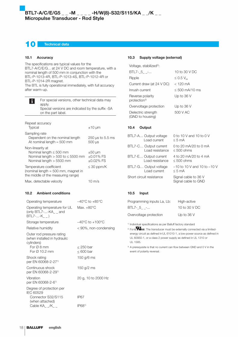
Accuracy10.1
The specifications are typical values for the BTL7-A/C/E/G... at 24 V DC and room temperature, with a nominal length of 500 mm in conjunction with the BTL-P-1013-4R, BTL-P-1013-4S, BTL-P-1012-4R or BTL-P-1014-2R magnet.The BTL is fully operational immediately, with full accuracy after warm-up.
For special versions, other technical data may apply.Special versions are indicated by the suffix -SA on the part label.
Repeat accuracy Typical ±10 µm
Sampling rate Dependent on the nominal length At nominal length = 500 mm
250 µs to 5.5 ms500 µs
Non-linearity at Nominal length ≤ 500 mm Nominal length > 500 to ≤ 5500 mm Nominal length > 5500 mm
±50 µm±0.01% FS±0.02% FS
Temperature coefficient(nominal length = 500 mm, magnet in the middle of the measuring range)
≤ 30 ppm/K
Max. detectable velocity 10 m/s
Ambient conditions10.2
Operating temperature -40°C to +85°C
Operating temperature for UL (only BTL7-...-KA_ _ and BTL7-...-K_ _ )
Max. +80°C
Storage temperature -40°C to +100°C
Relative humidity < 90%, non-condensing
Outer rod pressure rating (when installed in hydraulic cylinders)
For Ø 8 mm < 250 barFor Ø 10.2 mm < 600 bar
Shock rating per EN 60068-2-271)
150 g/6 ms
Continuous shock per EN 60068-2-291)
150 g/2 ms
Vibration per EN 60068-2-61)
20 g, 10 to 2000 Hz
Degree of protection per IEC 60529
Connector S32/S115 (when attached)
IP67
Cable KA_ _/K_ _ IP681)
Supply voltage (external)10.3
Voltage, stabilized2):
BTL7-_5_ _-... 10 to 30 V DC
Ripple ≤ 0.5 Vss
Current draw (at 24 V DC) < 120 mA
Inrush current ≤ 500 mA/10 ms
Reverse polarity protection3)
Up to 36 V
Overvoltage protection Up to 36 V
Dielectric strength (GND to housing)
500 V AC
Output10.4
BTL7-A… Output voltage Load current
0 to 10 V and 10 to 0 V≤ 5 mA
BTL7-C… Output current Load resistance
0 to 20 mA/20 to 0 mA≤ 500 ohms
BTL7-E… Output current Load resistance
4 to 20 mA/20 to 4 mA≤ 500 ohms
BTL7-G… Output voltage Load current
-10 to 10 V and 10 to -10 V≤ 5 mA
Short circuit resistance Signal cable to 36 VSignal cable to GND
Input10.5
Programming inputs La, Lb: High-active
BTL7-_5_ _-... 10 to 30 V DC
Overvoltage protection Up to 36 V
1) Individual specifications as per Balluff factory standard2) For : The transducer must be externally connected via a limited-
energy circuit as defined in UL 61010-1, a low-power source as defined in
UL 60950-1, or a class 2 power supply as defined in UL 1310 or
UL 1585.3) A prerequisite is that no current can flow between GND and 0 V in the
event of polarity reversal.
Technical data10
BTL7-A/C/E/G5 _ _ -M _ _ _ _ -H/W(8)-S32/S115/KA _ _/K _ _Micropulse Transducer - Rod Style
www.balluff.com 19english
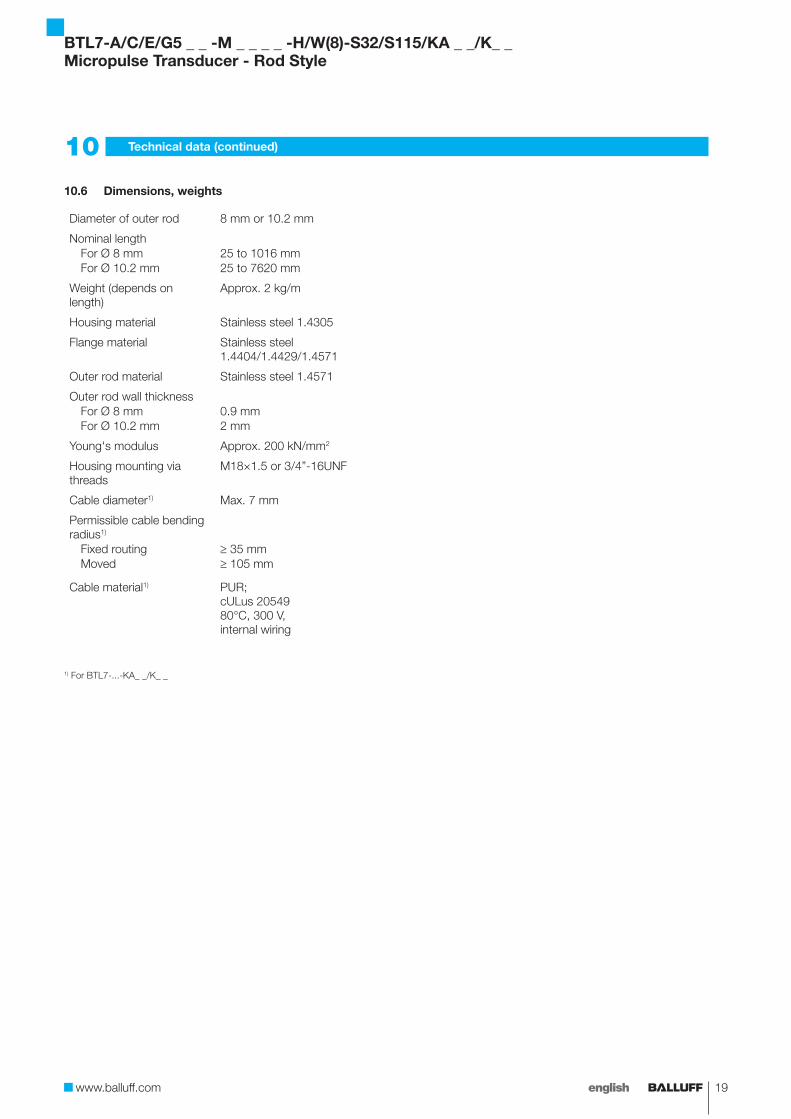
Dimensions, weights10.6
Diameter of outer rod 8 mm or 10.2 mm
Nominal lengthFor Ø 8 mm 25 to 1016 mmFor Ø 10.2 mm 25 to 7620 mm
Weight (depends on length)
Approx. 2 kg/m
Housing material Stainless steel 1.4305
Flange material Stainless steel 1.4404/1.4429/1.4571
Outer rod material Stainless steel 1.4571
Outer rod wall thicknessFor Ø 8 mm 0.9 mmFor Ø 10.2 mm 2 mm
Young's modulus Approx. 200 kN/mm2
Housing mounting via threads
M18×1.5 or 3/4”-16UNF
Cable diameter1) Max. 7 mm
Permissible cable bending radius1)
Fixed routing ≥ 35 mmMoved ≥ 105 mm
Cable material1) PUR; cULus 2054980°C, 300 V, internal wiring
1) For BTL7-...-KA_ _/K_ _
10 Technical data (continued)
BTL7-A/C/E/G5 _ _ -M _ _ _ _ -H/W(8)-S32/S115/KA _ _/K_ _Micropulse Transducer - Rod Style
20 english
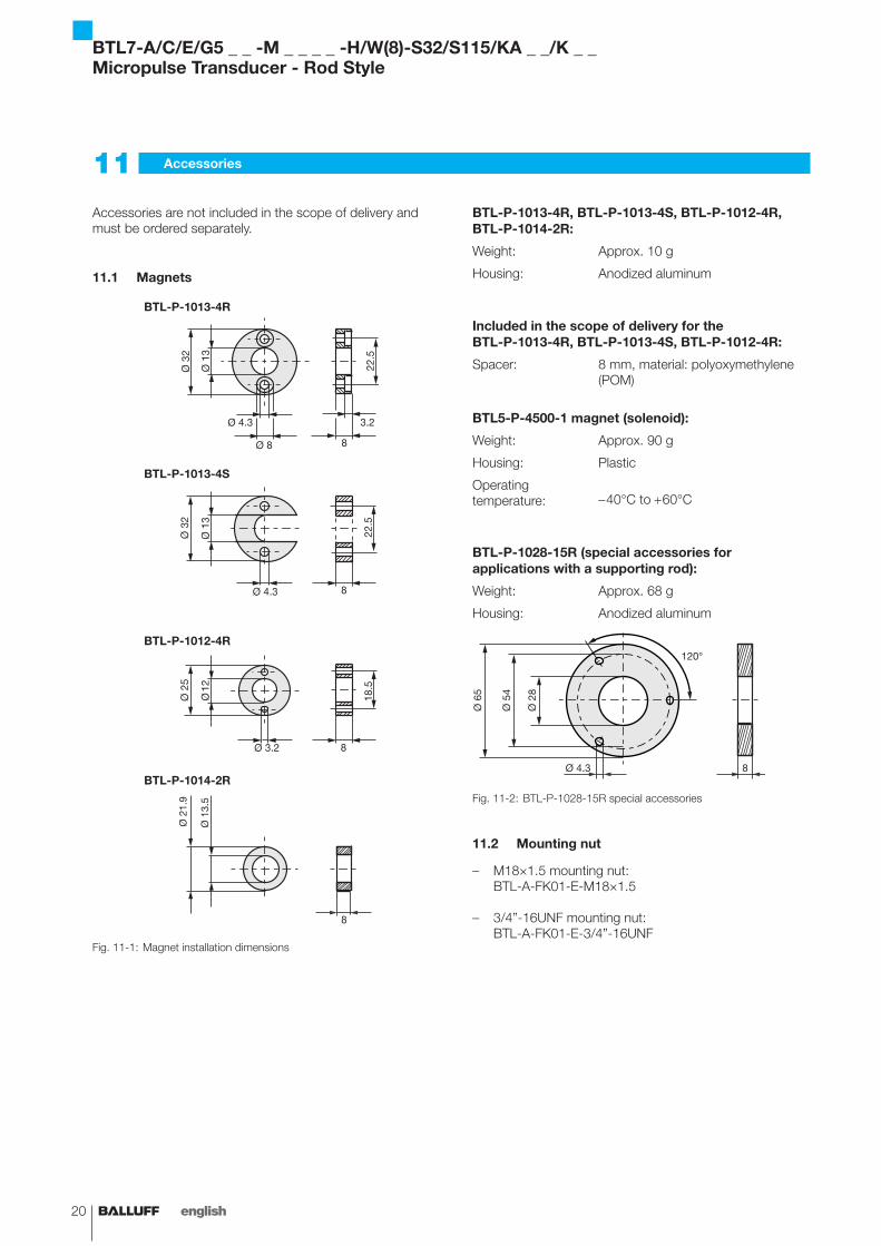
Accessories are not included in the scope of delivery and must be ordered separately.
Magnets11.1
BTL-P-1013-4R
BTL-P-1013-4S
BTL-P-1012-4R
BTL-P-1014-2R
BTL-P-0814-GR-PAFFig. 11-1: Magnet installation dimensions
BTL-P-1013-4R, BTL-P-1013-4S, BTL-P-1012-4R, BTL-P-1014-2R:
Weight: Approx. 10 g
Housing: Anodized aluminum
Included in the scope of delivery for the BTL-P-1013-4R, BTL-P-1013-4S, BTL-P-1012-4R:
Spacer: 8 mm, material: polyoxymethylene (POM)
BTL5-P-4500-1 magnet (solenoid):
Weight: Approx. 90 g
Housing: Plastic
Operating temperature:
- 40°C to + 60°C
BTL-P-1028-15R (special accessories for applications with a supporting rod):
Weight: Approx. 68 g
Housing: Anodized aluminum
Ø 4.3
120°
Ø 2
8
Ø 5
4
Ø 6
5
8
Fig. 11-2: BTL-P-1028-15R special accessories
Mounting nut11.2
M18×1.5 mounting nut: –BTL-A-FK01-E-M18×1.5
3/4”-16UNF mounting nut: –BTL-A-FK01-E-3/4”-16UNF
Accessories11
BTL7-A/C/E/G5 _ _ -M _ _ _ _ -H/W(8)-S32/S115/KA _ _/K _ _Micropulse Transducer - Rod Style

www.balluff.com 21english
Connectors and cables11.3
BKS-S32/S33M-00, freely configurable11.3.1
BKS-S32M-00Straight connector, freely configurableM16 per IEC 130-9, 8-pin
~ 62
Fig. 11-3: Connector BKS-S32M-00
BKS-S33M-00Angled connector, freely configurableM16 per IEC 130-9, 8-pin
Ø 1
8
31
37.2
Ø 20
Ø 6
- Ø
8 ~ 54
Fig. 11-4: Connector BKS-S33M-00
BKS-S232/S233-PU-_ _, preassembled11.3.2
BKS-S232-PU-_ _Straight connector, molded, preassembledM16, 8-pinVarious cable lengths can be ordered, e.g. BKS-S232-PU-05: Cable length 5 m
Ø 2
0
66
Fig. 11-5: Connector BKS-S232-PU-_ _
BKS-S233-PU-_ _Angled connector, molded, preassembledM16, 8-pinVarious cable lengths can be ordered, e.g. BKS-S233-PU-05: Cable length 5 m
Ø 20
46
48.5
Fig. 11-6: Connector BKS-S233-PU-_ _
Fig. 11-7: Connector BKS-S233-PU-_ _, axial outlet
Pin Color
1 YE yellow
2 GY gray
3 PK pink
4 RD red
5 GN green
6 BU blue
7 BN brown
8 WH white
BKS-S232/S233-PU-_ _ pin assignmentTab. 11-1:
11 Accessories (continued)
BTL7-A/C/E/G5 _ _ -M _ _ _ _ -H/W(8)-S32/S115/KA _ _/K_ _Micropulse Transducer - Rod Style
22 english
11 Accessories (continued)
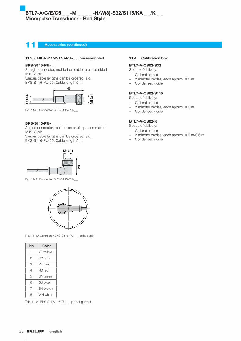
BKS-S115/S116-PU-_ _, preassembled11.3.3
BKS-S115-PU-_ _Straight connector, molded-on cable, preassembledM12, 8-pinVarious cable lengths can be ordered, e.g. BKS-S115-PU-05: Cable length 5 m
43
Ø 1
3.5
M12
x1
Fig. 11-8: Connector BKS-S115-PU-_ _
BKS-S116-PU-_ _Angled connector, molded-on cable, preassembledM12, 8-pinVarious cable lengths can be ordered, e.g. BKS-S116-PU-05: Cable length 5 m
28
M12x1
Fig. 11-9: Connector BKS-S116-PU-_ _
Fig. 11-10: Connector BKS-S116-PU-_ _, axial outlet
Pin Color
1 YE yellow
2 GY gray
3 PK pink
4 RD red
5 GN green
6 BU blue
7 BN brown
8 WH white
BKS-S115/116-PU-_ _ pin assignmentTab. 11-2:
Calibration box11.4
BTL7-A-CB02-S32Scope of delivery:
Calibration box –2 adapter cables, each approx. 0.3 m –Condensed guide –
BTL7-A-CB02-S115Scope of delivery:
Calibration box –2 adapter cables, each approx. 0.3 m –Condensed guide –
BTL7-A-CB02-KScope of delivery:
Calibration box –2 adapter cables, each approx. 0.3 m/0.6 m –Condensed guide –
BTL7-A/C/E/G5 _ _ -M _ _ _ _ -H/W(8)-S32/S115/KA _ _/K _ _Micropulse Transducer - Rod Style

www.balluff.com 23english
Type code breakdown12
BTL7 - E 5 0 0 - M0500 - H - S32
Micropulse transducer
Interface:
A = Analog interface, voltage output 0 to 10 V
G = Analog interface, voltage output -10 to 10 V
C = Analog interface, current output 0 to 20 mA
E = Analog interface, current output 4 to 20 mA
Supply voltage:
5 = 10 to 30 V DC
Output gradient:
00 = Rising (e.g. C_00 = 0 to 20 mA)
10 = Rising + falling (e.g. A_10 = 10 to 0 V and 0 to 10 V)
70 = Falling (e.g. C_70 = 20 to 0 mA)
Nominal stroke (4-digit):
M0500 = Metric specification in mm, nominal length 500 mm
Rod version, fastening:
H = Metric mounting thread M18×1.5, O-ring, rod diameter 10.2 mm
W = 3/4”-16UNF thread, O-ring, rod diameter 10.2 mm
H8 = Metric mounting thread M18×1.5, O-ring, rod diameter 8 mm
W8 = 3/4”-16UNF thread, O-ring, rod diameter 8 mm
Electrical connection:
S32 = 8-pin, M16 plug per IEC 130-9, axial
S115 = 8-pin, M12 plug, axial
KA05 = Cable, 5 m, axial
K05 = Cable, 5 m, radial
BTL7-A/C/E/G5 _ _ -M _ _ _ _ -H/W(8)-S32/S115/KA _ _/K_ _Micropulse Transducer - Rod Style
24 english
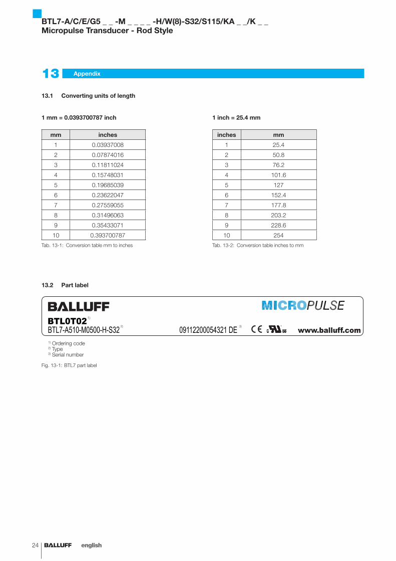
Converting units of length13.1
1 mm = 0.0393700787 inch
mm inches
1 0.03937008
2 0.07874016
3 0.11811024
4 0.15748031
5 0.19685039
6 0.23622047
7 0.27559055
8 0.31496063
9 0.35433071
10 0.393700787
Conversion table mm to inchesTab. 13-1:
1 inch = 25.4 mm
inches mm
1 25.4
2 50.8
3 76.2
4 101.6
5 127
6 152.4
7 177.8
8 203.2
9 228.6
10 254
Conversion table inches to mmTab. 13-2:
Appendix13
Part label13.2
BTL0T02BTL7-A510-M0500-H-S32 09112200054321 DE
Fig. 13-1: BTL7 part label
1) Ordering code2) Type3) Serial number
1) 3) 2)
BTL7-A/C/E/G5 _ _ -M _ _ _ _ -H/W(8)-S32/S115/KA _ _/K _ _Micropulse Transducer - Rod Style

No.
880
224-
726
E .
00.0
0000
0 . E
ditio
n 10
10; S
ubje
ct to
mod
ifica
tion.
www.balluff.com
Headquarters GermanyBalluff GmbHSchurwaldstrasse 973765 Neuhausen a.d.F.Phone + 49 7158 173-0Fax +49 7158 [email protected]
Global Service Center
GermanyBalluff GmbHSchurwaldstrasse 973765 Neuhausen a.d.F.Phone +49 7158 173-370Fax +49 7158 [email protected]
US Service Center
USABalluff Inc.8125 Holton DriveFlorence, KY 41042Phone (859) 727-2200Toll-free 1-800-543-8390Fax (859) 727-4823 [email protected]