transformer excitation current test - engineering home …engineering.richmondcc.edu/courses/eus...
TRANSCRIPT
Transformer Excitation Current Test

Ideal Transformer
• Transformers allow energy transfer from one electrical circuit to another
• For a perfect transformer, no losses would occur energy in = energy out

Practical Transformer
In reality, a transformer has lots of elements that dissipate energy while the unit is energized. These lost are includes to: • Copper Losses • Leakage flux • Reluctance • Iron Losses
Losses are all tied to the Design and Construction of the unit A change in the losses measured therefore shows us a change
in the internal state of a transformer

Why We do the Test
• Abnormal core grounds • Winding faults: shorts, open circuits • LTC problems • Manufacturing defects

Physics (I Know u love it !! )
• Applying a voltage to one winding of a transformer causes current to flow • The current generates a magnetic field around the core • This generates changes in the magnetic state of the core • Magnetic energy will begin to circulate in the core – this is called magnetic flux • With the secondary open, only as much current as is needed to get flux moving
enters the winding – this is called the excitation current

Physics Ct.
• Why don’t we measure the flux directly? –We can’t , you’d have to be inside the transformer while it was
energized
• Magnetizing current, on the other hand, is easy to measure & record –Will be VOLTAGE SENSITIVE, so comparison requires same
voltage be applied
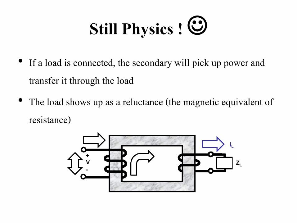
Still Physics ! • If a load is connected, the secondary will pick up power and
transfer it through the load • The load shows up as a reluctance (the magnetic equivalent of
resistance)
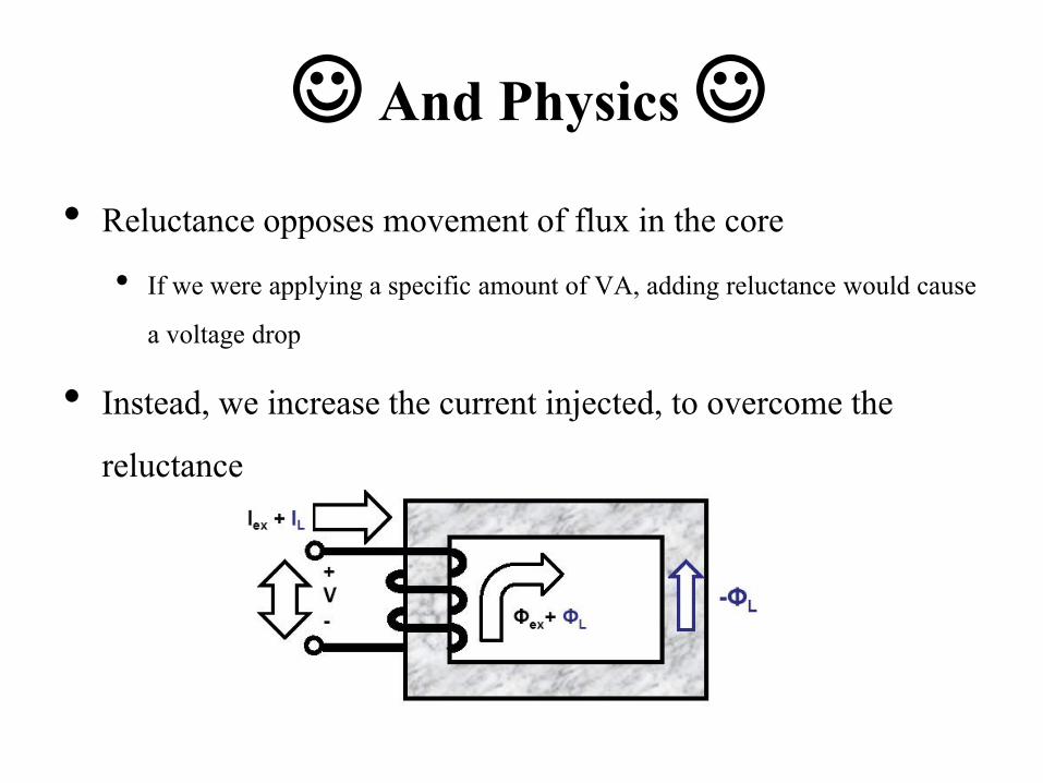
And Physics • Reluctance opposes movement of flux in the core
• If we were applying a specific amount of VA, adding reluctance would cause a voltage drop
• Instead, we increase the current injected, to overcome the reluctance
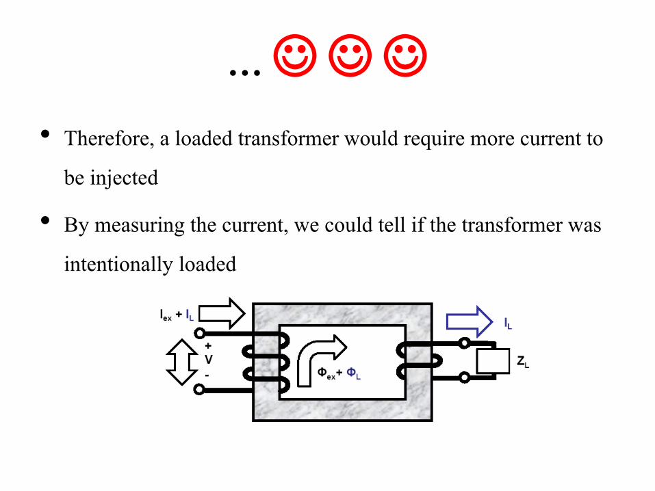
… • Therefore, a loaded transformer would require more current to
be injected • By measuring the current, we could tell if the transformer was
intentionally loaded

Excitation Test Principal
• When an AC Voltage Source, such as a Doble Test Set, is placed on a transformer, a small current will flow.
• This small current is the Magnetizing Current: the current required to magnetize the Transformer core with the Magnetic Flux ∅𝑚𝑎𝑔 . This Magnetizing Current is the Excitation Current we measure and record.
• This Magnetic Flux will induce a voltage across the secondary windings: V2
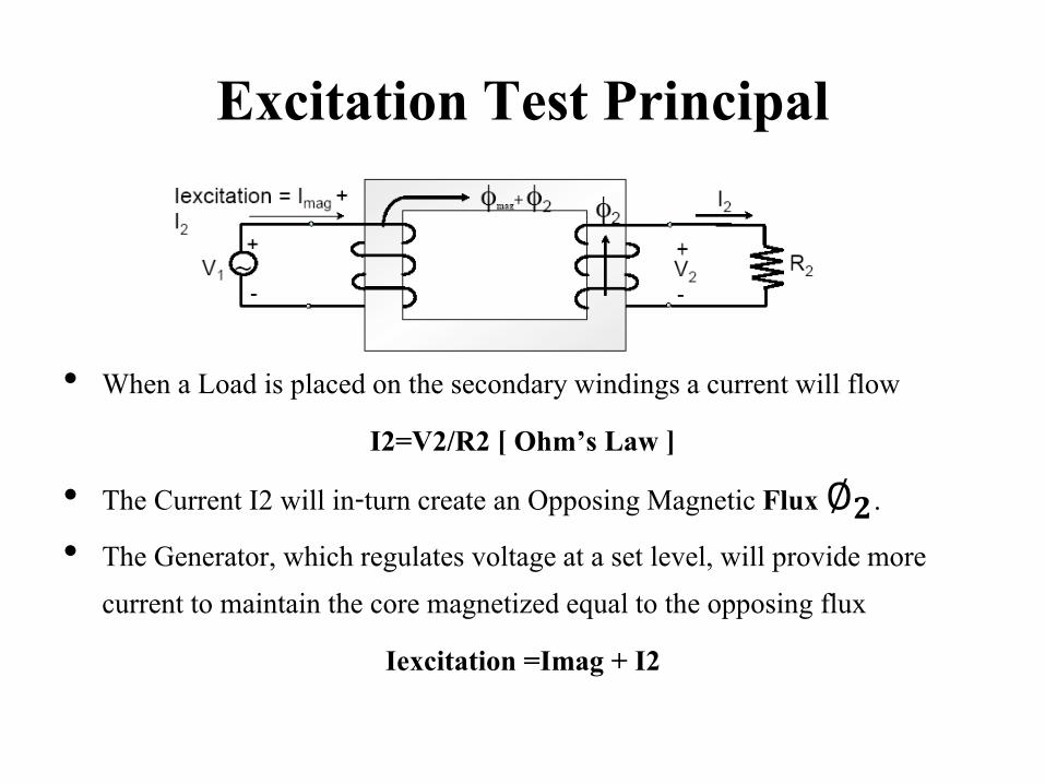
Excitation Test Principal
• When a Load is placed on the secondary windings a current will flow I2=V2/R2 [ Ohm’s Law ]
• The Current I2 will in-turn create an Opposing Magnetic Flux ∅𝟐. • The Generator, which regulates voltage at a set level, will provide more
current to maintain the core magnetized equal to the opposing flux Iexcitation =Imag + I2

Finding Turn to Turn Fault
• If a fault develops in the secondary windings, this fault will act as a load across the faulted windings drawing a current 𝐼𝑓𝑎𝑢𝑙𝑡
• As a result, the Excitation Current will go up due to the opposing flux created by the fault [∅𝑓𝑎𝑢𝑙𝑡]
A Fault will cause Excitation Current to Increase

Finding Grounded Winding
• If the secondary winding has a grounded neutral and one of the windings develops a fault to ground, grounded windings will draw a fault current
• As a result, the Excitation Current will go up due to the opposing flux created by the fault [∅𝑓𝑎𝑢𝑙𝑡]
A grounded winding on a transformer with a grounded neutral will cause the Excitation Current to go up.

Effect of Preventive Autotransformer
• An LTC preventative autotransformer also functions as a load when bridging • As taps are stepped through, this can create recognizable step patterns When a LTC transitioning device such as a Preventive Autotransformer is
in the bridging position the excitation current goes up.
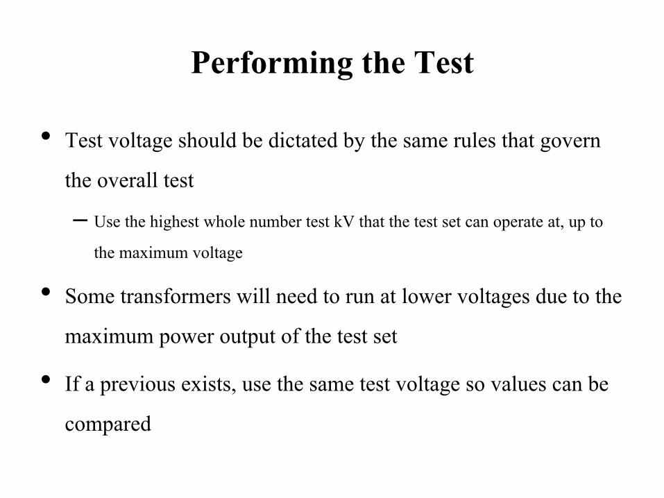
Performing the Test
• Test voltage should be dictated by the same rules that govern the overall test – Use the highest whole number test kV that the test set can operate at, up to
the maximum voltage
• Some transformers will need to run at lower voltages due to the maximum power output of the test set
• If a previous exists, use the same test voltage so values can be compared

Performing the Test • For new units, or for investigating events:
– Test all LTC contacts & reversing switch – –1-16R + N + 1L, 1-16L + N + 1R, or all
• Test each DETC position with the LTC in neutral – If the DETC has never been operated, do not move it
• For routine unit maintenance • Test extreme LTC contacts & reversing switch
–16R + 1R + N + 1L or 16L + 1L + N + 1R Leave the DETC in the normal operating position

Performing the Test
• Aim to measure every phase individually – With wye windings with buried neutrals (not accessible), this may not be
possible
• If low voltage winding has a neutral, ground it during test to check for turn-ground faults
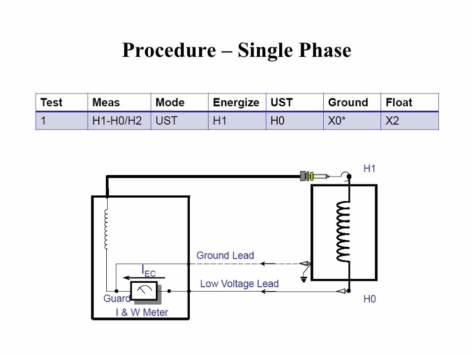
Procedure – Single Phase
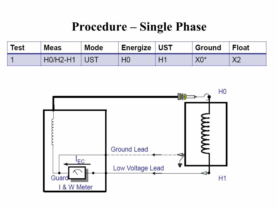
Procedure – Single Phase
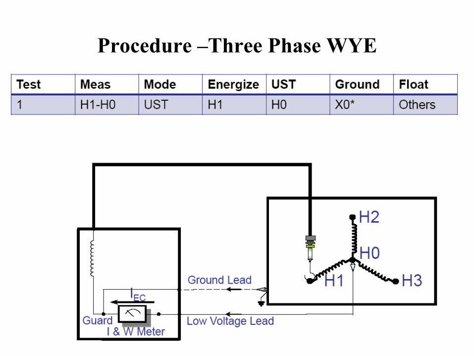
Procedure –Three Phase WYE
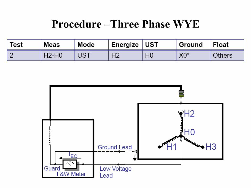
Procedure –Three Phase WYE
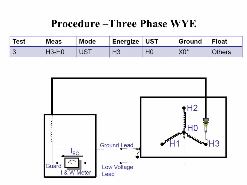
Procedure –Three Phase WYE

Procedure – Three Phase Delta (A Phase)

Procedure – Three Phase Delta (B Phase)

Procedure – Three Phase Delta (C phase)

Analysis of Test Data

Phase Patterns • The currents/watts measured on a three phase unit will show a pattern across
the phases – There are three expected patterns
• The phase pattern is tied to both the measurement and the core configuration • Phase patterns arise from the core configuration
– Recall that an increased load leads to an increase reluctance, and thus an increased current injected
• Interacting with the core at different points will result in different reluctances, and thus different currents. – Reluctance sums similar to resistance

Phase Patterns
For simplicity assume that each section has a reluctance of 1 Ω

Outer Legs (Phase A and C)
The same holds true when you energize
Phase C

Middle Legs (Phase B)
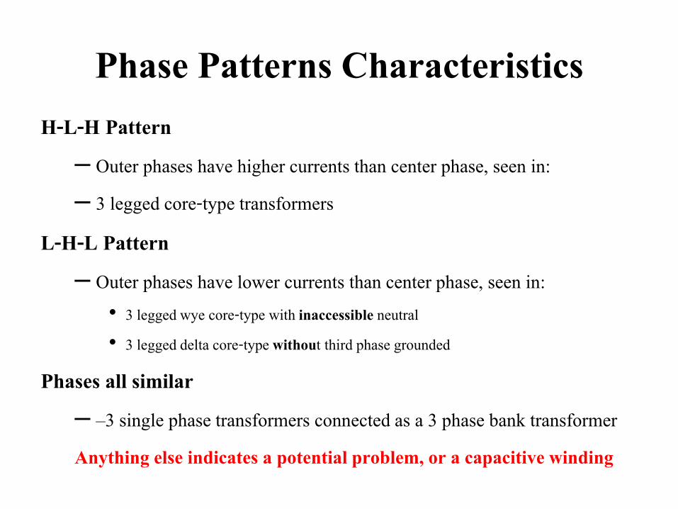
Phase Patterns Characteristics H-L-H Pattern
– Outer phases have higher currents than center phase, seen in: – 3 legged core-type transformers
L-H-L Pattern – Outer phases have lower currents than center phase, seen in:
• 3 legged wye core-type with inaccessible neutral • 3 legged delta core-type without third phase grounded
Phases all similar – –3 single phase transformers connected as a 3 phase bank transformer Anything else indicates a potential problem, or a capacitive winding

DETC Pattern • For each phase, the DETC pattern should be identified by comparing data at
different DETC positions. The approach to DETC pattern analysis depends on whether the unit is an inductive or capacitive specimen.
• When a given phase behaves as an INDUCTIVE specimen, the DETC pattern follows the change in the primary turns, e.g., as DETC moves from position with a maximum number of turns to one with a minimum number of turns (i.e., higher to lower nameplate voltage) the MAGNITUDE of both current and losses INCREASES.
• When a given phase behaves as a CAPACITIVE specimen, the current DETC pattern may or may NOT follow the change in the primary turns. This may distort the phase pattern as well. The influence of capacitance can be distinguished from that of a defect by inspecting the loss DETC pattern, which, in the absence of a defect, does follow the change in the primary turns.

Analysis of Test Result • Check the pattern: two similar high readings and one low reading is normal
(though there are exceptions) • When Tap Changers are present, consider the pattern within the phase • For three-phase units, compare both high readings with the following
criterion: – Readings <= 50 mA, difference should not exceed 10% – Readings > 50 mA, differences should not exceed 5%
• For single phase units both readings should be compared using the same above criterion
• Compare Normal test to alternate tests; results should be similar for a winding in good condition
Analysis of Test Result • If the core is magnetized an irregular pattern (high, medium, low readings)
will be present and you will be unable to compare results effectively. A true problem could be masked, therefore core should be demagnetized and test should be repeated
• Compare readings to previous results. Ensure that the same voltage was used for both tests for consistent numerical comparison
• If unusual results are obtained, consider performing an alternate test to further investigate

UNDERSTAND PHYSICS BEHIND DATA AND YOU WILL DO FINE!
YES IT IS ALL ABOUT PHYSICS