transformer failure
DESCRIPTION
Transformer Failure IncidentTRANSCRIPT

10/30/06 E:/wkg_fdr/ppt/slide_prsnt1.ppt
Date of failure : 18.06.05 at 9:18 AM18.06.05 at 9:18 AM
Type of failure : NewType of failure : New
FAILURE ANALYSIS
C-43 Transformer’s 33 KV side cable failure
Back
Incidence Detail
A.K.Gupta
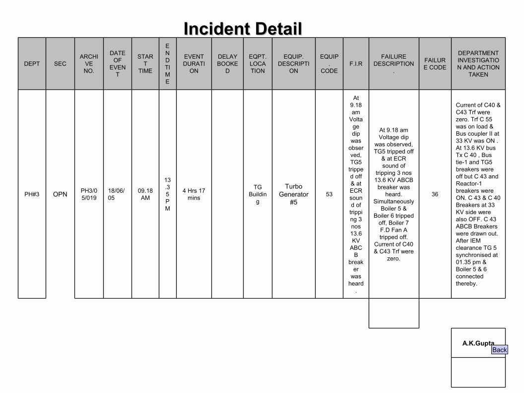
Current of C40 & C43 Trf were zero. Trf C 55 was on load & Bus coupler II at 33 KV was ON . At 13.6 KV bus Tx C 40 , Bus tie-1 and TG5 breakers were off but C 43 and Reactor-1 breakers were ON. C 43 & C 40 Breakers at 33 KV side were also OFF. C 43 ABCB Breakers were drawn out. After IEM clearance TG 5 synchronised at 01.35 pm & Boiler 5 & 6 connected thereby.
36
At 9.18 am Voltage dip
was observed, TG5 tripped off
& at ECR sound of
tripping 3 nos 13.6 KV ABCB
breaker was heard.
Simultaneously Boiler 5 &
Boiler 6 tripped off, Boiler 7 F.D Fan A tripped off.
Current of C40 & C43 Trf were
zero.
At 9.18 am
Voltage dip was
observed, TG5
tripped off & at ECR sound of tripping 3 nos 13.6 KV
ABCB
breaker
was heard
.
53Turbo
Generator #5
TG Buildin
g 4 Hrs 17
mins
13.35 PM
09.18 AM
18/06/05
PH3/05/019OPNPH#3
DEPARTMENT INVESTIGATION AND ACTION
TAKEN
FAILURE CODE
FAILURE DESCRIPTION
.F.I.R
EQUIP.
CODE
EQUIP. DESCRIPTI
ON
EQPT. LOCATION
DELAY BOOKE
D
EVENT DURATI
ON
END TIME
START
TIME
DATE OF
EVENT
ARCHIVE NO.
SECDEPT
Back
Incident DetailIncident Detail
10/30/06 E:/wkg_fdr/ppt/slide_prsnt1.ppt
Problem Statement :
C-43 Transformer cable failed during operation of this transformer causing tripping of TG # 5 , C-40 & C-43 transformer.Approx. 7MW power was being evacuated through both transformers it at the time of tripping.
Back
10/30/06 E:/wkg_fdr/ppt/slide_prsnt1.ppt
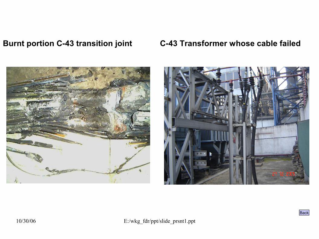
Burnt portion C-43 transition joint C-43 Transformer whose cable failed
Back
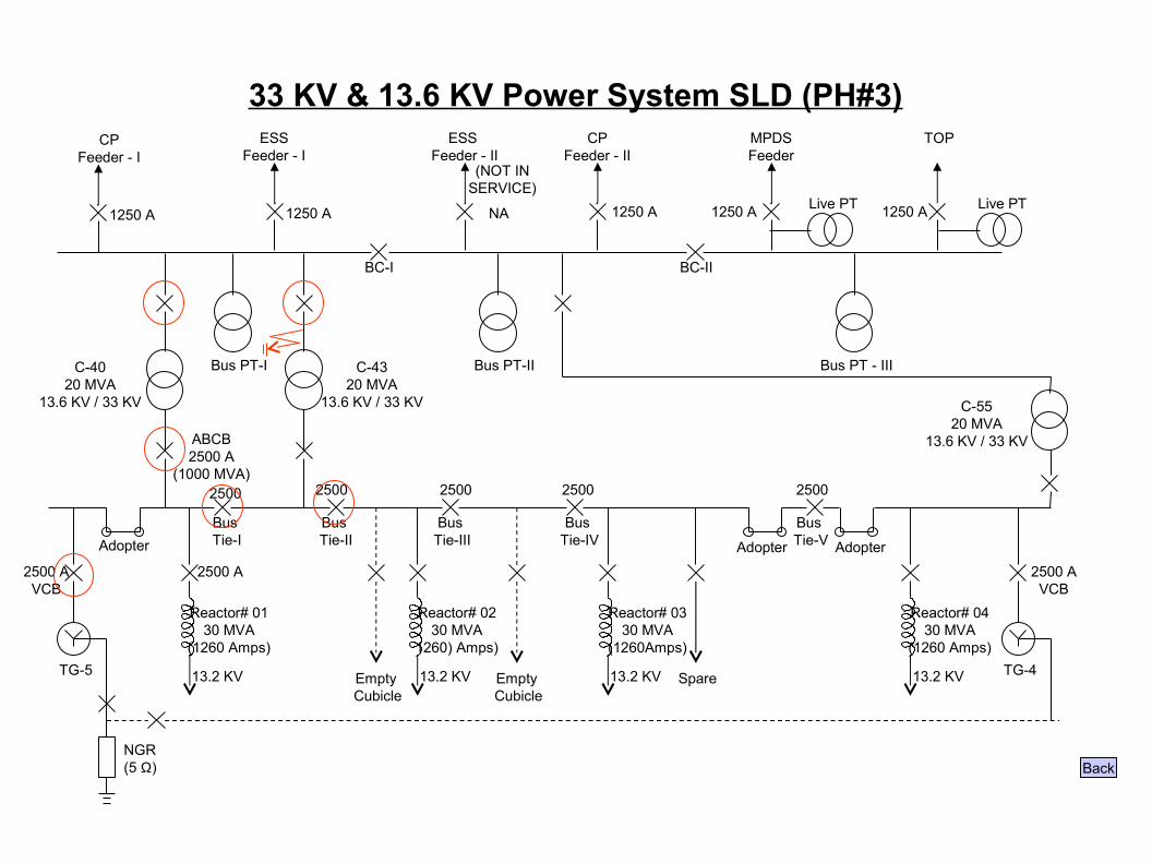
33 KV & 13.6 KV Power System SLD (PH#3)
NGR(5 Ω)
TG-5
2500 AVCB
Adopter
TG-4
2500 AVCB
13.2 KV
Bus Tie-I
2500 A
Reactor# 0130 MVA
(1260 Amps)
Bus Tie-II
Bus Tie-III
Bus Tie-IV
Bus Tie-V
Empty Cubicle
13.2 KV
Reactor# 0230 MVA
1260) Amps)
Empty Cubicle
13.2 KV
Reactor# 0330 MVA
(1260Amps)
Spare 13.2 KV
Reactor# 0430 MVA
(1260 Amps)
ABCB2500 A
(1000 MVA)2500
BC-I BC-II
CPFeeder - I
1250 A
ESSFeeder - I
1250 A
ESS Feeder - II
NA
CPFeeder - II
MPDSFeeder
TOP
(NOT INSERVICE)
Bus PT-IC-4020 MVA
13.6 KV / 33 KV
C-4320 MVA
13.6 KV / 33 KV
Bus PT-II
Live PT Live PT
Bus PT - III
C-5520 MVA
13.6 KV / 33 KV
1250 A 1250 A 1250 A
2500 2500 2500 2500
Adopter Adopter
Back
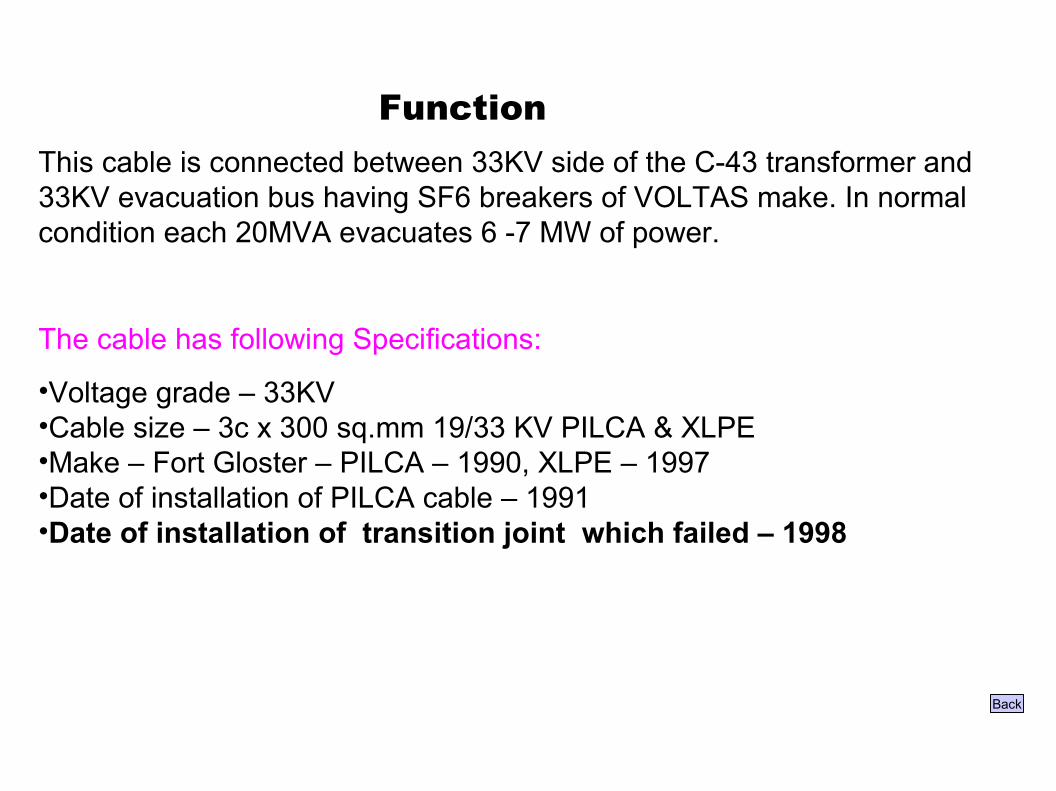
FunctionThis cable is connected between 33KV side of the C-43 transformer and 33KV evacuation bus having SF6 breakers of VOLTAS make. In normal condition each 20MVA evacuates 6 -7 MW of power.
The cable has following Specifications:
•Voltage grade – 33KV•Cable size – 3c x 300 sq.mm 19/33 KV PILCA & XLPE•Make – Fort Gloster – PILCA – 1990, XLPE – 1997•Date of installation of PILCA cable – 1991•Date of installation of transition joint which failed – 1998
Back
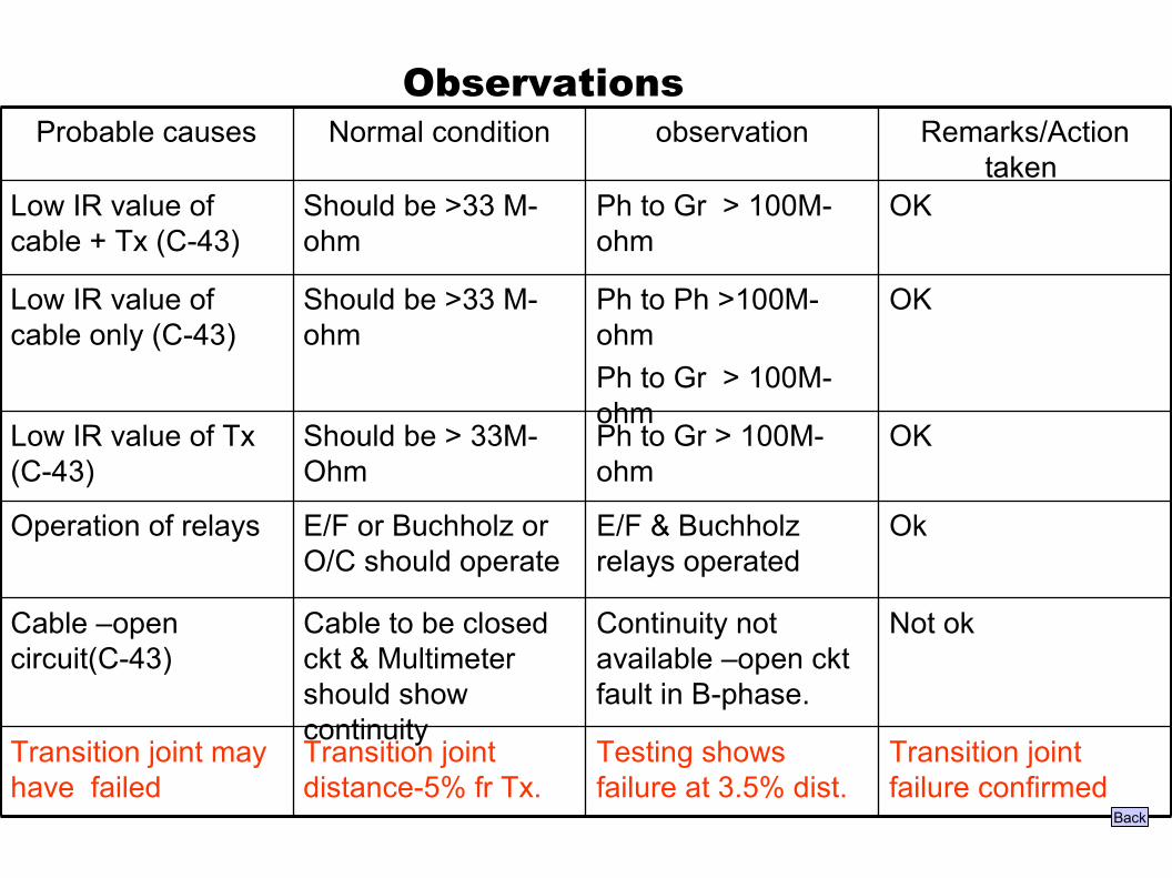
Observations
Not okContinuity not available –open ckt fault in B-phase.
Cable to be closed ckt & Multimeter should show continuity
Cable –open circuit(C-43)
Transition joint failure confirmed
Testing shows failure at 3.5% dist.
Transition joint distance-5% fr Tx.
Transition joint may have failed
OkE/F & Buchholz relays operated
E/F or Buchholz or O/C should operate
Operation of relays
OKPh to Gr > 100M-ohm
Should be > 33M-Ohm
Low IR value of Tx (C-43)
OKPh to Ph >100M-ohmPh to Gr > 100M-ohm
Should be >33 M-ohm
Low IR value of cable only (C-43)
OKPh to Gr > 100M-ohm
Should be >33 M-ohm
Low IR value of cable + Tx (C-43)
Remarks/Action taken
observationNormal conditionProbable causes
Back
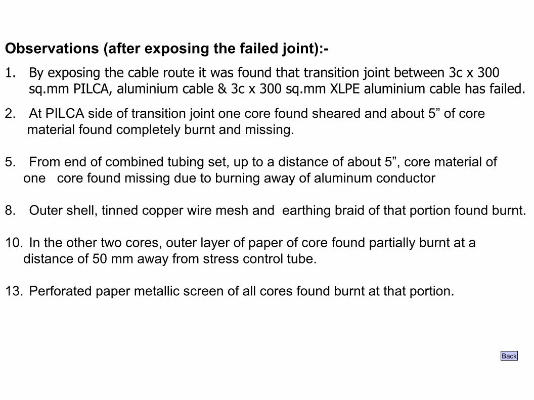
Observations (after exposing the failed joint):-1. By exposing the cable route it was found that transition joint between 3c x 300
sq.mm PILCA, aluminium cable & 3c x 300 sq.mm XLPE aluminium cable has failed.
2. At PILCA side of transition joint one core found sheared and about 5” of core material found completely burnt and missing.
5. From end of combined tubing set, up to a distance of about 5”, core material of one core found missing due to burning away of aluminum conductor
8. Outer shell, tinned copper wire mesh and earthing braid of that portion found burnt.
10. In the other two cores, outer layer of paper of core found partially burnt at a distance of 50 mm away from stress control tube.
13. Perforated paper metallic screen of all cores found burnt at that portion.
Back
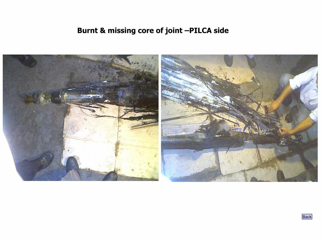
Burnt & missing core of joint –PILCA side
Back
Root Cause Identified
Insulation failure occurred in cable joint due to oil barrier tube not shrunk properly during installation and voids were left at that portion - Human error
Back
Remedial Action taken
Rejointing of failed cable’s transition joint got done by Reychem expert in presence of TISCO expert agency (i.e. Service & Transmission) as per guidelines given by Reychem.
Back
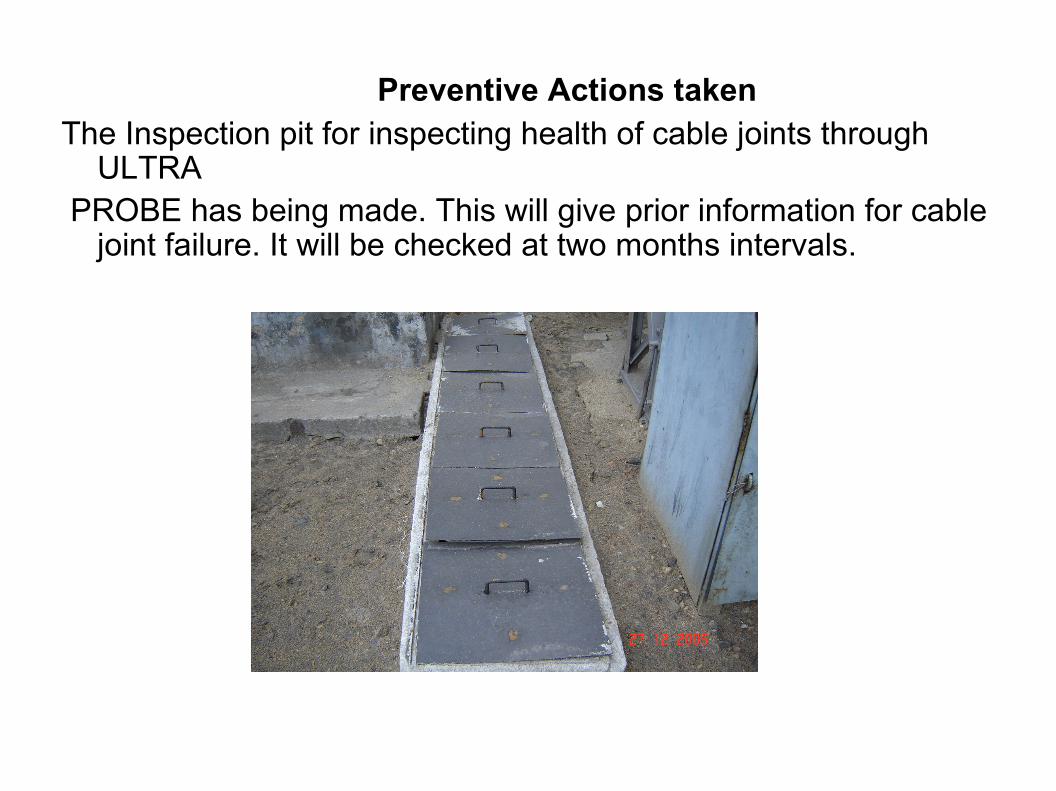
Preventive Actions taken The Inspection pit for inspecting health of cable joints through
ULTRA PROBE has being made. This will give prior information for cable
joint failure. It will be checked at two months intervals.

Horizontal Deployment
1. It has been decided that all such HT cable joints of 33kv and above shall be put into inspection pit for periodic monitoring.
3. Healths of these cable shall be monitored at regular intervals through ULTRA PROBE.
Back

THANKING YOU
10/30/06 E:/wkg_fdr/ppt/slide_prsnt1.ppt
Date of failure : 01.06.05 ( 3.30PM to 5.15PM).06.05 ( 3.30PM to 5.15PM)
Type of failure : NewType of failure : New
FAILURE ANALYSIS – 4
Failure of Dynodrive – A in Boiler-6
Back
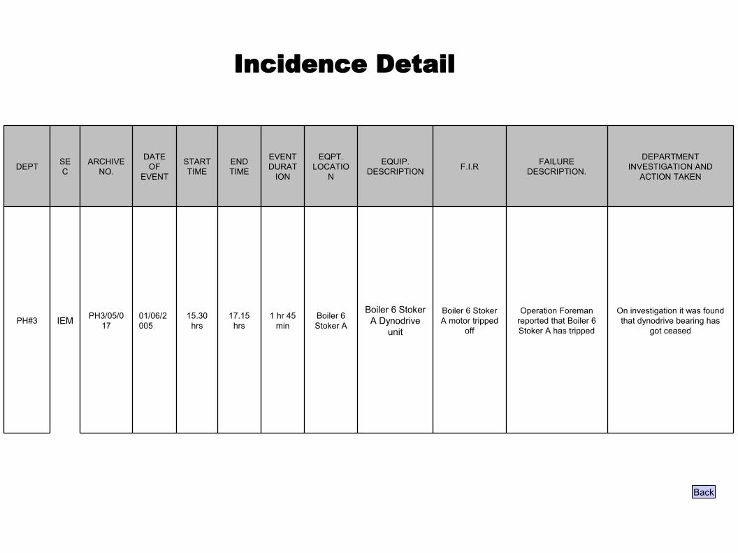
Incidence Detail
On investigation it was found that dynodrive bearing has
got ceased
Operation Foreman reported that Boiler 6 Stoker A has tripped
Boiler 6 Stoker A motor tripped
off
Boiler 6 Stoker A Dynodrive
unit
Boiler 6 Stoker A
1 hr 45 min
17.15 hrs
15.30 hrs
01/06/2005
PH3/05/017IEMPH#3
DEPARTMENT INVESTIGATION AND
ACTION TAKEN
FAILURE DESCRIPTION.F.I.REQUIP.
DESCRIPTION
EQPT. LOCATIO
N
EVENT DURAT
ION
END TIME
START TIME
DATE OF
EVENT
ARCHIVE NO.
SECDEPT
Back
10/30/06 E:/wkg_fdr/ppt/slide_prsnt1.ppt
Problem Statement
Boiler # 6 stoker A tripped as reported by the operator.
Back
Function (contd)Control Circuit Diagram of Dynodrive for speed control:
Back

Observations
Not OKBearing clearance
Not OKFound dustyShould be free from dust
Bearing
Not OK.Not rotating freely- bearing found defective
Should rotate freely
Dyno drive unit jam
OKRotated freely by handShould rotate freely by hand
Stoker Gear jam
OKMotor rotated by hand & found free
Motor shaft should rotate freely
Motor bearing jam
OKProperly insulatedGood insulation of motor
Motor burnt
Remarks/Action taken
Observation Normal conditionProbable causes
Back

Analysis
From the observations Dynodrive unit was found jammed, bearing dusty and After cleaning the bearing clearance was found on higher side.
Root cause
Bearing got jammed due to dust ingression, which led to the failure.
Back
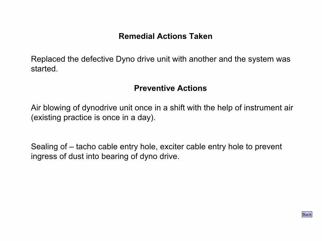
Remedial Actions Taken
Replaced the defective Dyno drive unit with another and the system was started.
Preventive Actions
Air blowing of dynodrive unit once in a shift with the help of instrument air (existing practice is once in a day).
Sealing of – tacho cable entry hole, exciter cable entry hole to prevent ingress of dust into bearing of dyno drive.
Back

Horizontal Deployment
1. It has been decided by the TOP management that all such HT cable joints 33kv and above shall be put into inspection pit for periodic monitoring.
3. Healths of these cable shall be monitored at regular intervals through ULTRA PROBE.
Back
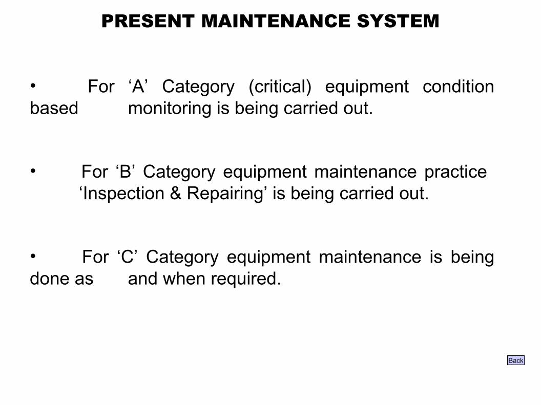
PRESENT MAINTENANCE SYSTEM
• For ‘A’ Category (critical) equipment condition based monitoring is being carried out.
• For ‘B’ Category equipment maintenance practice ‘Inspection & Repairing’ is being carried out.
• For ‘C’ Category equipment maintenance is being done as and when required.
Back
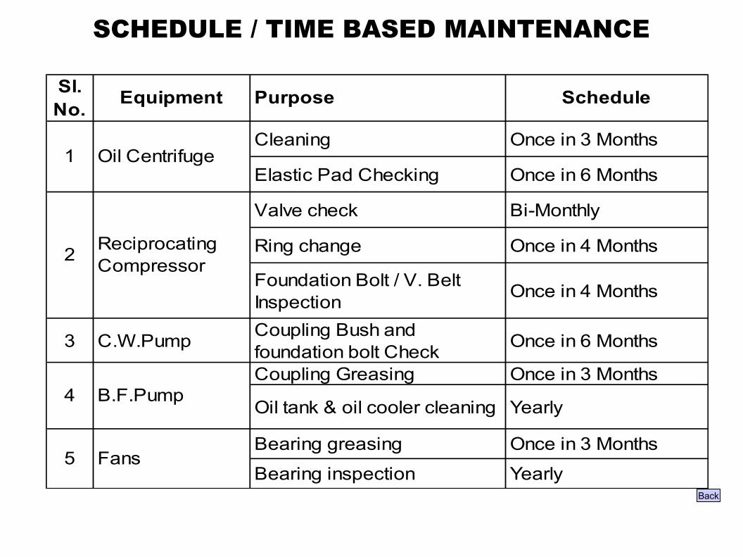
SCHEDULE / TIME BASED MAINTENANCE
Sl. No. Equipment Purpose Schedule
Cleaning Once in 3 Months
Elastic Pad Checking Once in 6 Months
Valve check Bi-Monthly
Ring change Once in 4 Months
Foundation Bolt / V. Belt Inspection Once in 4 Months
3 C.W.Pump Coupling Bush and foundation bolt Check Once in 6 Months
Coupling Greasing Once in 3 Months
Oil tank & oil cooler cleaning Yearly
Bearing greasing Once in 3 Months
Bearing inspection Yearly5 Fans
1 Oil Centrifuge
B.F.Pump4
2 Reciprocating Compressor
Back
CONDITION BASED MAINTENANCE
Now our focus is to shift from Time based maintenance to
condition based maintenance (CBM) to reduce maintenance
cost, increase equipment reliability and increase mean time to
repair.
Back

CONDITION MONITORING – PRESENT STATUS
On-lineOil temperature
Maint. Engg.MonthlyVibrationC.E.Pumps
On-lineExhaust pressure
Maint. Engg.MonthlyOil view analysis
Maint. Engg.Once in three monthsOil particle count
Maint. Engg.MonthlyOil Ferrography
On-lineAxial shift (MOP)
On-lineAxial shift (Turbine)
On-lineBearing metal temperature
On-lineFirst stage pressure
Maint. Engg.MonthlyBearing housing vibration
On-lineShaft vibration
Turbo Generator
Agency FrequencyParameterEquipment
Back
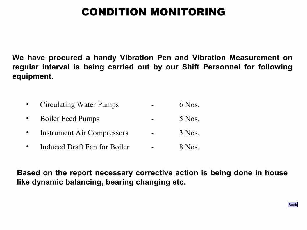
CONDITION MONITORING
We have procured a handy Vibration Pen and Vibration Measurement on regular interval is being carried out by our Shift Personnel for following equipment.
• Circulating Water Pumps - 6 Nos.
• Boiler Feed Pumps - 5 Nos.
• Instrument Air Compressors - 3 Nos.
• Induced Draft Fan for Boiler - 8 Nos.
Based on the report necessary corrective action is being done in house like dynamic balancing, bearing changing etc.
Back

LUBRICANTS IN USE
Boiler & Fan and Ash Plant bearingGrease6.
Screw Service Air CompressorUltra-10W5.
C.T.Fan GearboxSS-1504.Reciprocating Compressor, Stoker Primary GearboxSS-2203.
Stoker Gearbox secondary, Ash Plant GearboxSS-320 2.
Turbine, Boiler Feed PumpSP-681.
EquipmentLubricantSl. No.
Back

LUBRICATION MANAGEMENT
•Arresting leakages & sources of contamination
•Storage & disposal of Lubricant
•Standardization of Lubricant
Back

EARLIER
• SP 68
• SS150
• SS 220
• SS 320
• Ultra 10 W
• Grease (Lithium complex)
STANDARDIZATION OF LUBRICANT
WE ARE EXPLORING THE POSSIBILITY OF
STANDARDISATION
Back
PRESENT
• SP 68
• SS150
• SS 220
• SS 320
• Ultra 10 W
• Grease (Lithium complex)
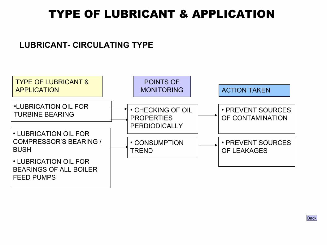
TYPE OF LUBRICANT & APPLICATION
LUBRICANT- CIRCULATING TYPE
•LUBRICATION OIL FOR TURBINE BEARING
• CHECKING OF OIL PROPERTIES PERDIODICALLY
• PREVENT SOURCES OF CONTAMINATION
• CONSUMPTION TREND
• PREVENT SOURCES OF LEAKAGES
• LUBRICATION OIL FOR COMPRESSOR’S BEARING / BUSH
• LUBRICATION OIL FOR BEARINGS OF ALL BOILER FEED PUMPS
POINTS OF MONITORING ACTION TAKEN
TYPE OF LUBRICANT & APPLICATION
Back
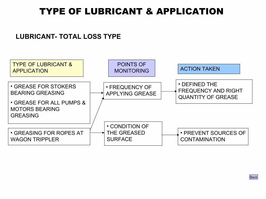
TYPE OF LUBRICANT & APPLICATION
LUBRICANT- TOTAL LOSS TYPE
• GREASE FOR STOKERS BEARING GREASING
• GREASE FOR ALL PUMPS & MOTORS BEARING GREASING
• FREQUENCY OF APPLYING GREASE
• DEFINED THE FREQUENCY AND RIGHT QUANTITY OF GREASE
• CONDITION OF THE GREASED SURFACE
• PREVENT SOURCES OF CONTAMINATION
• GREASING FOR ROPES AT WAGON TRIPPLER
POINTS OF MONITORING ACTION TAKEN
TYPE OF LUBRICANT & APPLICATION
Back
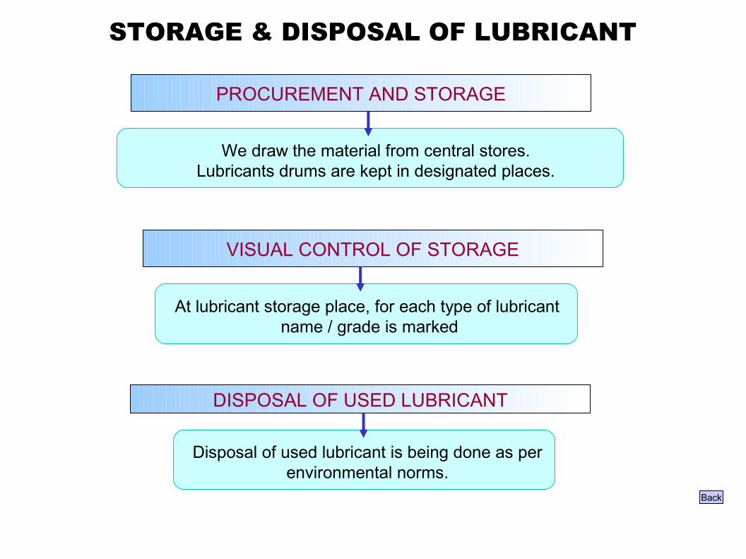
STORAGE & DISPOSAL OF LUBRICANT
We draw the material from central stores. Lubricants drums are kept in designated places.
PROCUREMENT AND STORAGE
VISUAL CONTROL OF STORAGE
At lubricant storage place, for each type of lubricant name / grade is marked
DISPOSAL OF USED LUBRICANT
Disposal of used lubricant is being done as per environmental norms.
Back
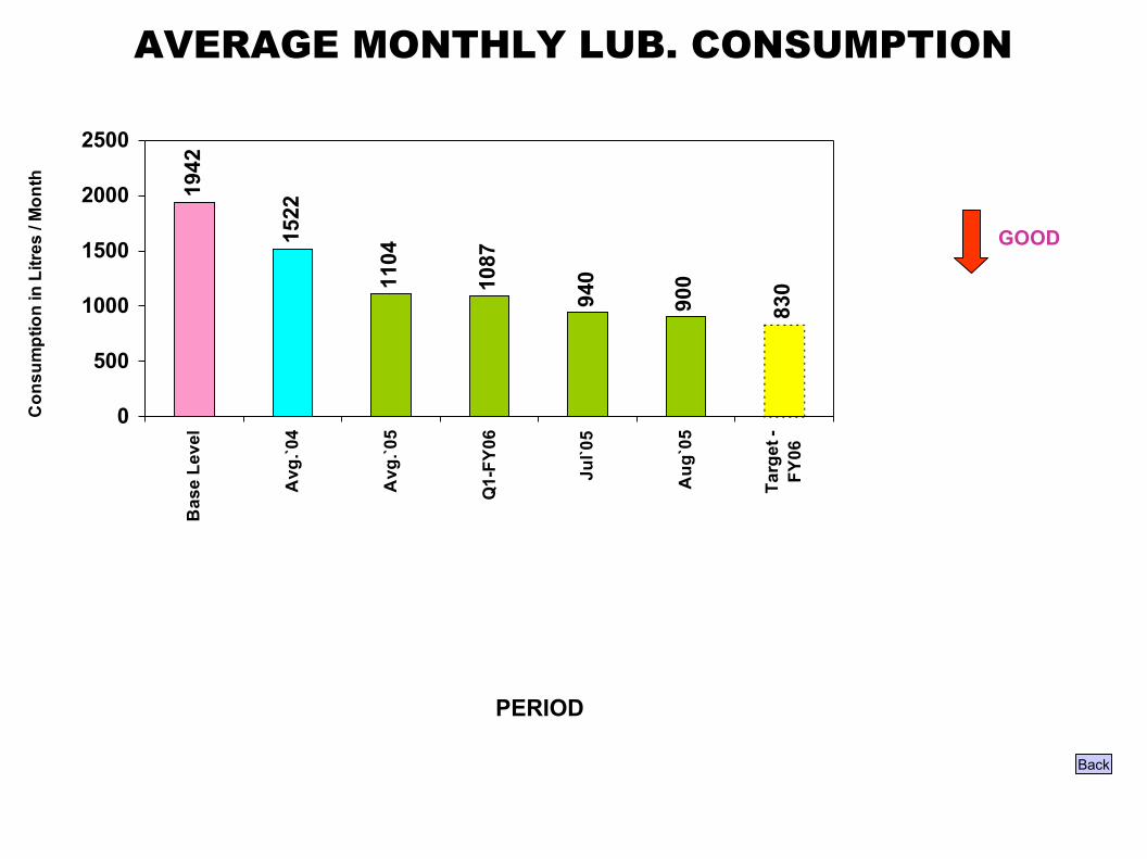
AVERAGE MONTHLY LUB. CONSUMPTION
1942
1522
1104
1087
940
900
830
0
500
1000
1500
2000
2500
Bas
e Le
vel
Avg
.`04
Avg
.`05
Q1-
FY06
Jul`0
5
Aug
`05
Targ
et -
FY06
Con
sum
ptio
n in
Litr
es /
Mon
th
GOOD
Back
PERIOD
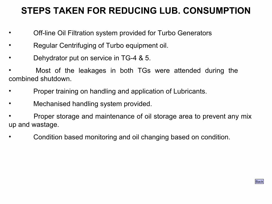
STEPS TAKEN FOR REDUCING LUB. CONSUMPTION
• Off-line Oil Filtration system provided for Turbo Generators
• Regular Centrifuging of Turbo equipment oil.
• Dehydrator put on service in TG-4 & 5.
• Most of the leakages in both TGs were attended during the combined shutdown.
• Proper training on handling and application of Lubricants.
• Mechanised handling system provided.
• Proper storage and maintenance of oil storage area to prevent any mix up and wastage.
• Condition based monitoring and oil changing based on condition.
Back

RESULT
1. Interruption rate
2. MTBF
3. Lubrication cost
4. Maintenance cost
Back

10
6
3
00
2
4
6
8
10
12
Base Level FY 05 FY 06 Target
No.
of I
nter
rupt
ion
No. Of Interuption (T.G)
INTERRUPTION OF TURBO GENERATORS
Goo
d
Back
0
PERIOD
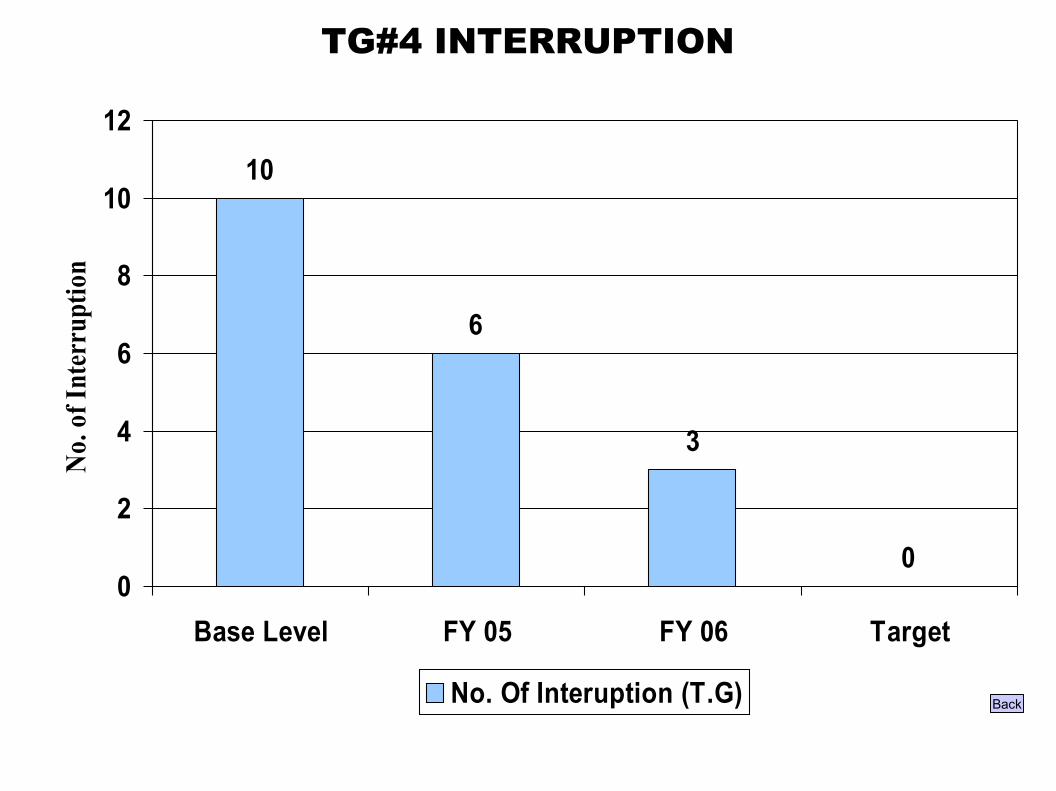
TG#4 INTERRUPTION
10
6
3
00
2
4
6
8
10
12
Base Level FY 05 FY 06 Target
No. o
f Int
erru
ptio
n
No. Of Interuption (T.G) Back
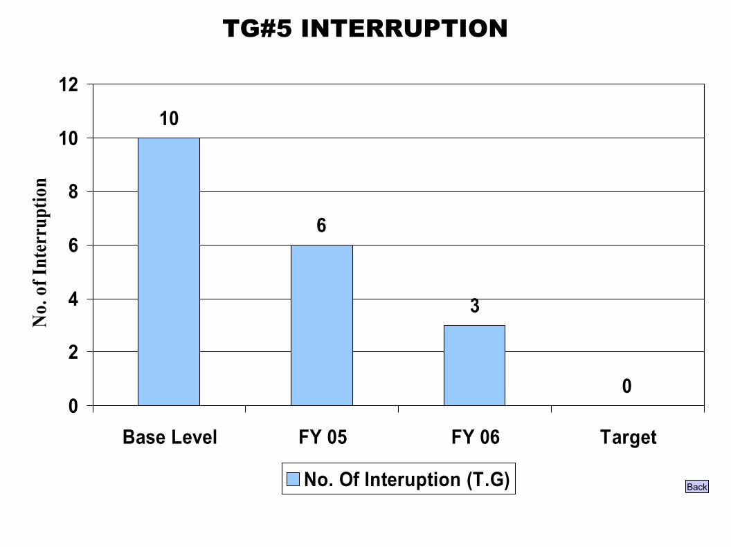
TG#5 INTERRUPTION
10
6
3
00
2
4
6
8
10
12
Base Level FY 05 FY 06 Target
No.
of I
nter
rupt
ion
No. Of Interuption (T.G) Back
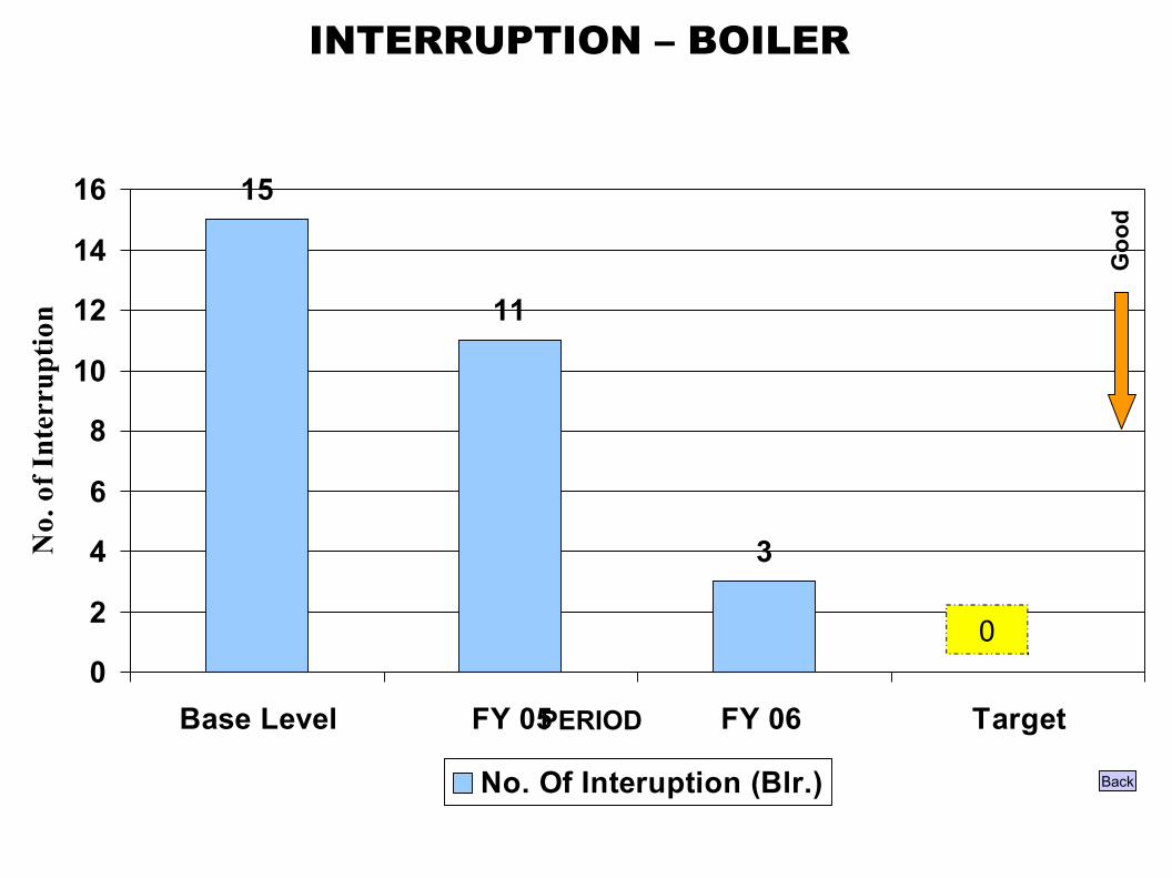
15
11
3
00
2
4
6
8
10
12
14
16
Base Level FY 05 FY 06 Target
No.
of I
nter
rupt
ion
No. Of Interuption (Blr.)
INTERRUPTION – BOILER
Goo
d
Back
0
PERIOD
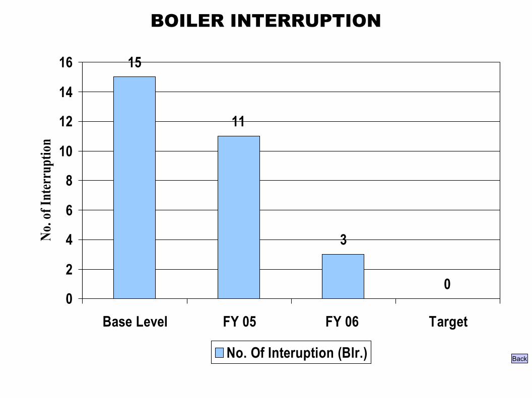
BOILER INTERRUPTION
15
11
3
00
2
4
6
8
10
12
14
16
Base Level FY 05 FY 06 Target
No. o
f Int
erru
ptio
n
No. Of Interuption (Blr.) Back
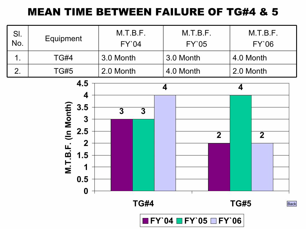
MEAN TIME BETWEEN FAILURE OF TG#4 & 5
4.0 Month
3.0 Month
M.T.B.F.FY`05
2.0 Month2.0 MonthTG#52.
4.0 Month3.0 MonthTG#41.
M.T.B.F.FY`06
M.T.B.F.FY`04
EquipmentSl. No.
3
2
3
44
2
00.5
11.5
22.5
33.5
44.5
TG#4 TG#5
M.T
.B.F
. (In
Mon
th)
FY`04 FY`05 FY`06
Back
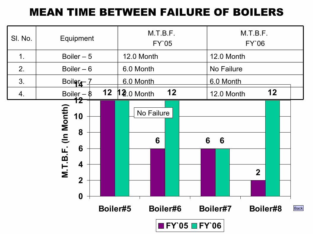
MEAN TIME BETWEEN FAILURE OF BOILERS
12.0 Month 2.0 MonthBoiler – 84.
6.0 Month 6.0 MonthBoiler – 73.
No Failure 6.0 MonthBoiler – 62.
12.0 Month 12.0 MonthBoiler – 51.
M.T.B.F. FY`06
M.T.B.F. FY`05
EquipmentSl. No.
12
6 6
2
12 12
6
12
0
2
4
6
8
10
12
14
Boiler#5 Boiler#6 Boiler#7 Boiler#8
M.T
.B.F
. (In
Mon
th)
FY`05 FY`06
Back
No Failure
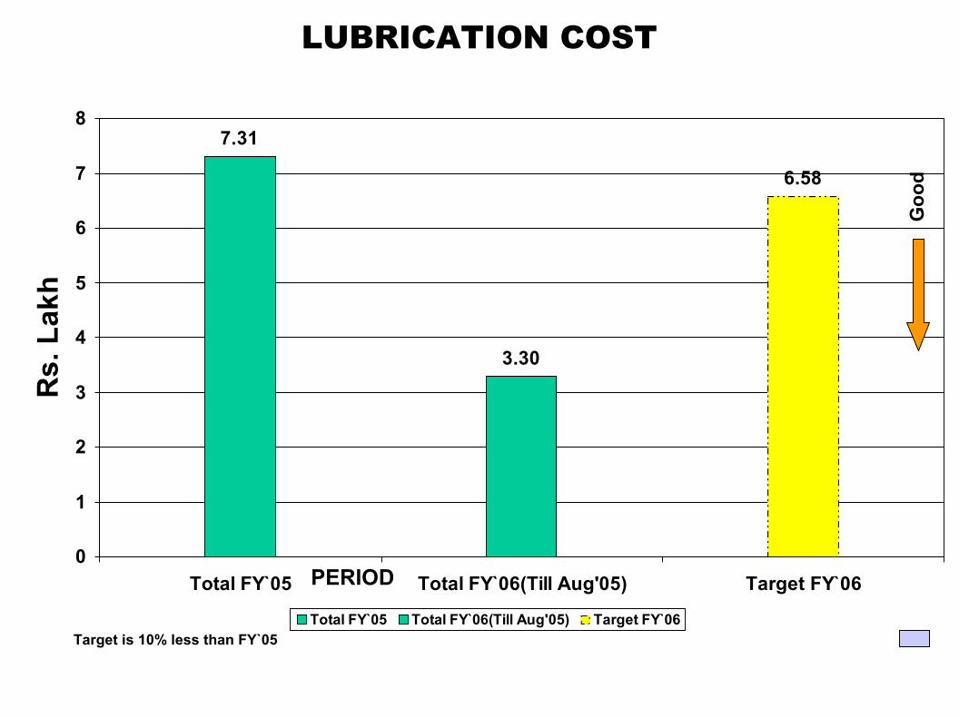
LUBRICATION COST
Back
7.31
3.30
6.58
0
1
2
3
4
5
6
7
8
Total FY`05 Total FY`06(Till Aug'05) Target FY`06
Rs.
Lak
h
Total FY`05 Total FY`06(Till Aug'05) Target FY`06Target is 10% less than FY`05
Goo
d
PERIOD
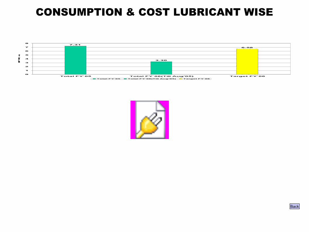
CONSUMPTION & COST LUBRICANT WISE
Back
7.31
3.30
6.58
0
1
2
3
4
5
6
7
8
Total FY`05 Total FY`06(Till Aug'05) Target FY`06
Rs
. L
ak
h
Total FY`05 Total FY`06(Till Aug'05) Target FY`06
Object 12

MAINT. COST EXPENDITURE
15.63
23.78 25.28 26.65
21.56
05
101520253035404550
Apr`05 May 05 Jun`05 Jul`05 Aug`05 Sep`05 Oct`05 Nov`05 Dec`05 Jan`06 Feb`06 Mar`06 Avg.YTD
Rs.
in L
akhs
PERIOD
GOOD
Monthly Target-23.75 L (FY`05-06)
2005 – 2006
Back
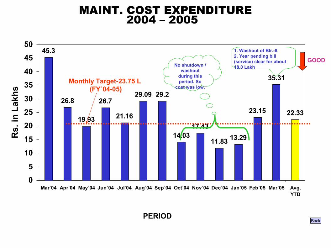
MAINT. COST EXPENDITURE
45.3
26.8
19.93
26.7
21.16
29.09 29.2
14.0317.43
11.83 13.29
23.15
35.31
22.33
05
1015
202530
3540
4550
Mar`04 Apr`04 May`04 Jun`04 Jul`04 Aug`04 Sep`04 Oct`04 Nov`04 Dec`04 Jan`05 Feb`05 Mar`05 Avg.YTD
Rs.
in L
akhs
GOOD
Monthly Target-23.75 L (FY`04-05)
No shutdown / washout
during this period. So
cost was low.
1. Washout of Blr.-8.2. Year pending bill (service) clear for about 18.0 Lakh
2004 – 2005
BackPERIOD

FUTURE ACTION PLAN
Analysis to be startedMTTR
Continuous Process.Skill gap matrix prepared and training programme prepared.
Enhancing skill for maintenance staff
To be introduced for Auxiliary equipment such as I.D.Fans, C.W.Pumps, C.E.Pumps, and Compressors,
Already provided for TGs and partially extended to other equipment.
Condition based Maintenance system
Dec`05Analysis to be started Spare / Inventory Management
To minimise Red Tag by supporting to JH ContinueRed Tag Management
Zero Per month by Dec`06ContinueFailure Analysis
TargetStatusActivities
Back

SPARE MANAGEMENT
1. IDENTIFICATION OF CRITICAL SPARES
2. PROCUREMENT
3. STORING
4. INVENTORY
Back

LIST OF CRITICAL SPARES
Back
45.3
26.8
19.93
26.7
21.16
29.09 29.2
14.0317.43
11.83 13.29
23.15
35.31
22.33
05
1015
202530
3540
4550
Mar`04 Apr`04 May`04 Jun`04 Jul`04 Aug`04 Sep`04 Oct`04 Nov`04 Dec`04 Jan`05 Feb`05 Mar`05 Avg.YTD
Rs. in La
khs
Object 16
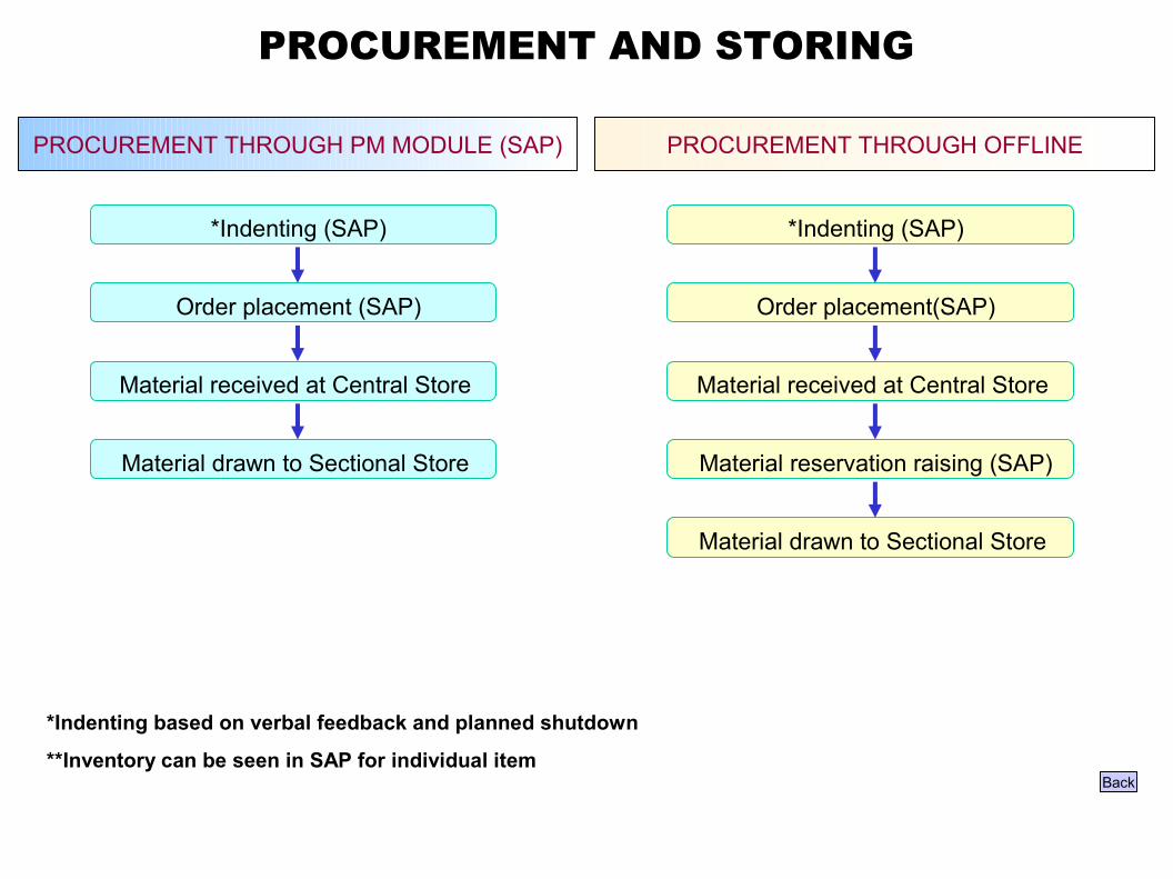
PROCUREMENT AND STORING
Back
*Indenting (SAP)
PROCUREMENT THROUGH PM MODULE (SAP)
Order placement (SAP)
Material received at Central Store
Material drawn to Sectional Store
*Indenting (SAP)
PROCUREMENT THROUGH OFFLINE
Order placement(SAP)
Material received at Central Store
Material reservation raising (SAP)
Material drawn to Sectional Store
*Indenting based on verbal feedback and planned shutdown
**Inventory can be seen in SAP for individual item
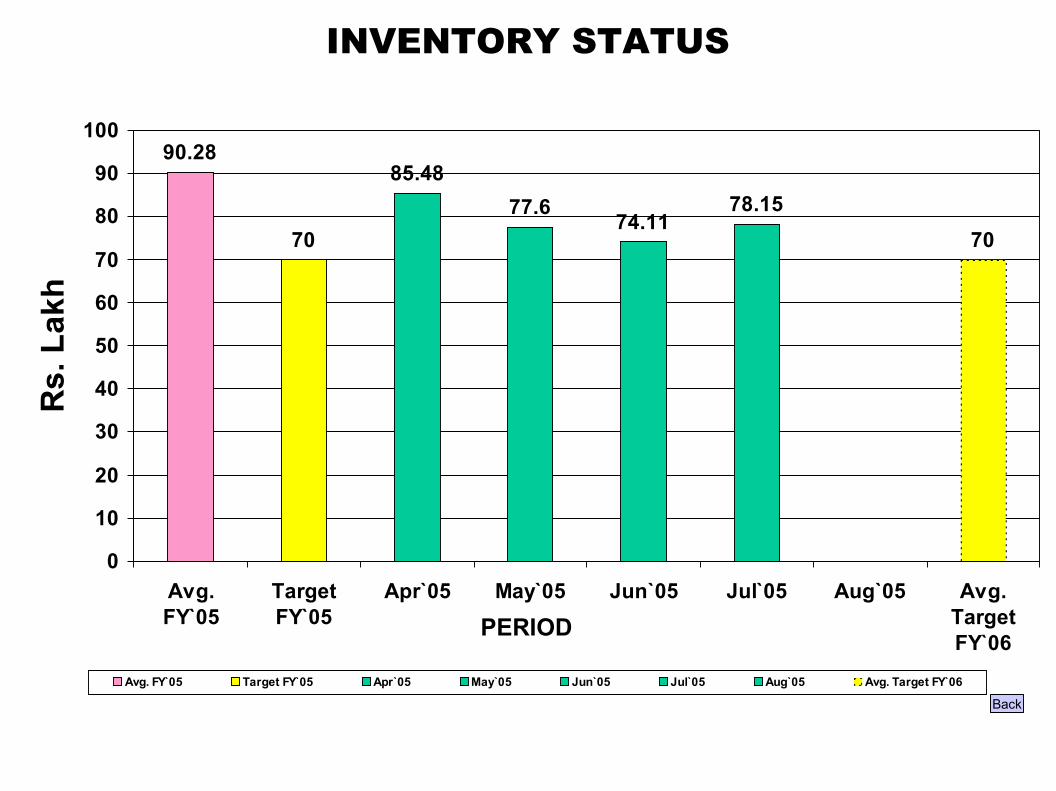
INVENTORY STATUS
Back
90.28
70
85.4877.6
74.1178.15
70
0
10
20
30
40
50
60
70
80
90
100
Avg.FY`05
TargetFY`05
Apr`05 May`05 Jun`05 Jul 05 Aug`05 Avg.TargetFY`06
Rs.
Lak
h
Avg. FY`05 Target FY`05 Apr`05 May`05 Jun`05 Jul`05 Aug`05 Avg. Target FY`06
PERIOD
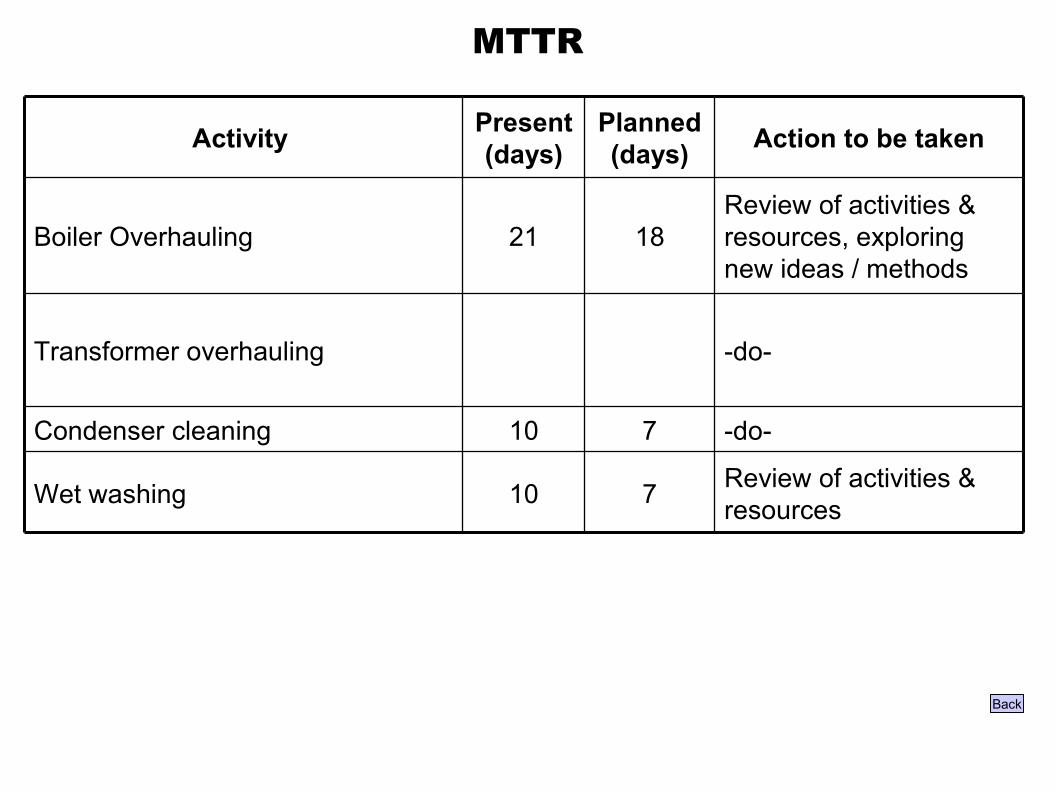
MTTR
Back
Review of activities & resources, exploring new ideas / methods
1821Boiler Overhauling
Review of activities & resources710Wet washing
-do-710Condenser cleaning
-do-Transformer overhauling
Action to be takenPlanned (days)
Present (days)Activity
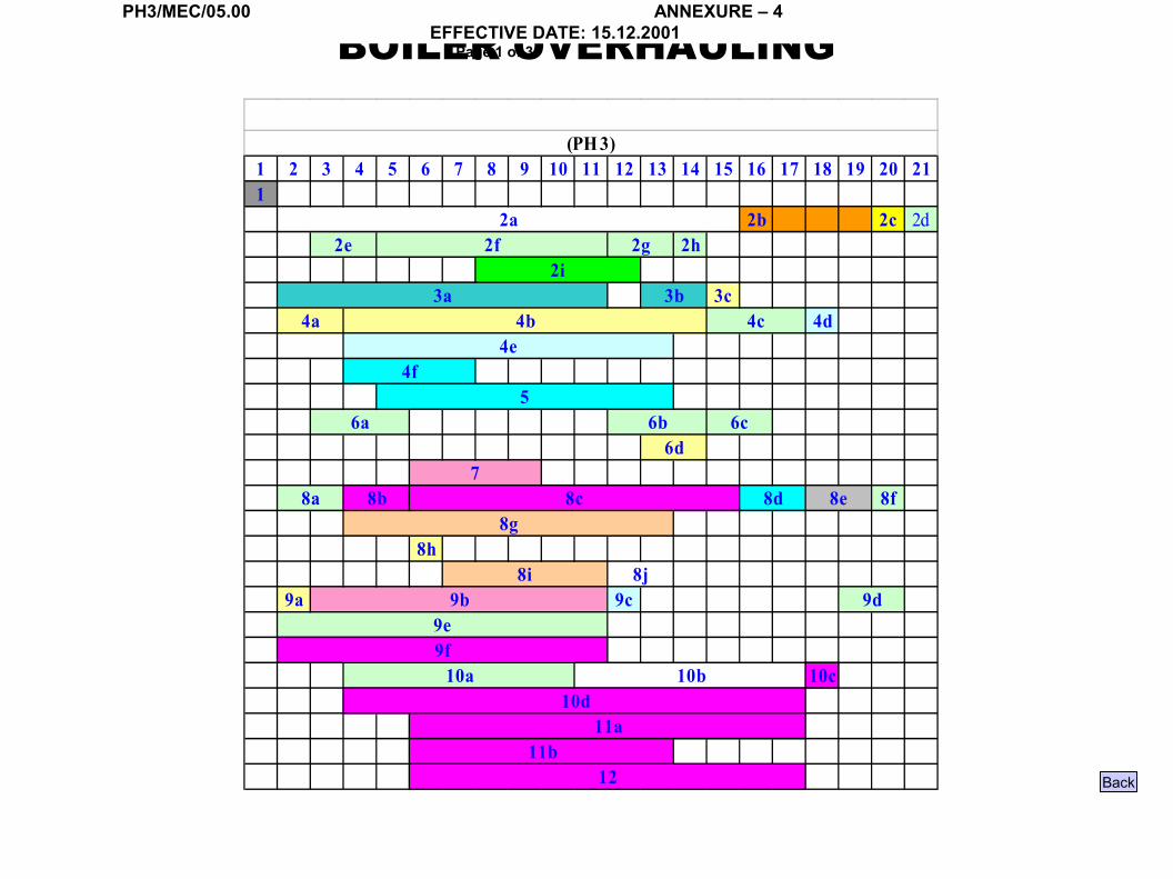
BOILER OVERHAULINGPH3/MEC/05.00 ANNEXURE – 4
EFFECTIVE DATE: 15.12.2001Page 1 of 3
1 2 3 4 5 6 7 8 9 10 11 12 13 14 15 16 17 18 19 20 211
2b 2c 2d2h
3c4d
8f
8h
9a 9c
10c
11b12
10a 10b10d
11a
9b 9d9e9f
8d 8e8g
8i 8j
6d7
8a 8b 8c
56a 6b 6c
4c4e
4f
2i3a 3b
4a 4b
(PH 3)
2a2e 2f 2g
Back

BOILER OVERHAULING – ACTIVITIES PH3/MEC/05.00 ANNEXURE – 4
EFFECTIVE DATE: 15.12.2001Page 1 of 3
Object 19
Object 20
Object 21
Back

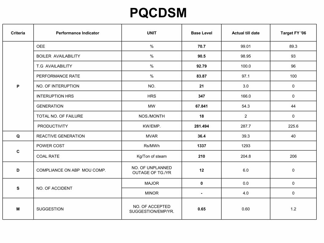
PQCDSM
1.20.600.65NO. OF ACCEPTED SUGGESTION/EMP/YR.SUGGESTIONM
04.0-MINOR
00.00MAJORNO. OF ACCIDENTS
06.012NO. OF UNPLANNED OUTAGE OF TG./YRCOMPLIANCE ON ABP MOU COMP.D
206204.8210Kg/Ton of steamCOAL RATE
12931337Rs/MWhPOWER COSTC
4039.336.4MVARREACTIVE GENERATIONQ
225.6287.7281.494KW/EMP. PRODUCTIVITY
0218NOS./MONTHTOTAL NO. OF FAILURE
4454.367.841MWGENERATION
0166.0347HRSINTERUPTION HRS
03.021NO.NO. OF INTERUPTION
10097.183.87%PERFORMANCE RATE
96100.092.79%T.G AVAILABILITY
9398.9590.5%BOILER AVAILABILITY
89.399.0170.7%OEE
P
Target FY '06Actual till dateBase LevelUNITPerformance IndicatorCriteria
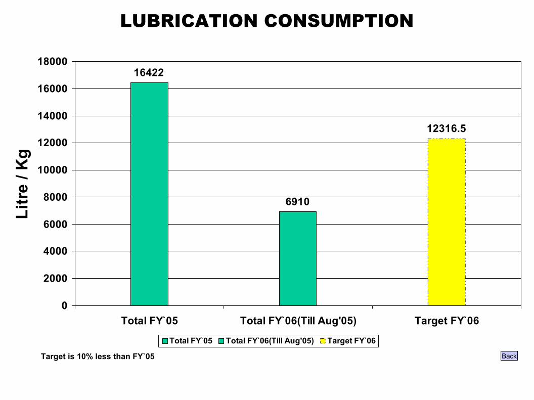
LUBRICATION CONSUMPTION
Back
16422
6910
12316.5
0
2000
4000
6000
8000
10000
12000
14000
16000
18000
Total FY`05 Total FY`06(Till Aug'05) Target FY`06
Litr
e / K
g
Total FY`05 Total FY`06(Till Aug'05) Target FY`06
Target is 10% less than FY`05
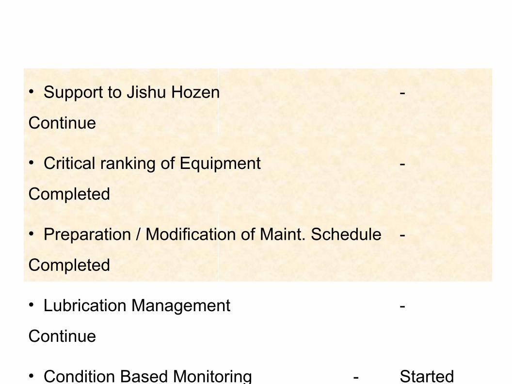
• Support to Jishu Hozen -
Continue
• Critical ranking of Equipment -
Completed
• Preparation / Modification of Maint. Schedule -
Completed
• Lubrication Management -
Continue
• Condition Based Monitoring - Started
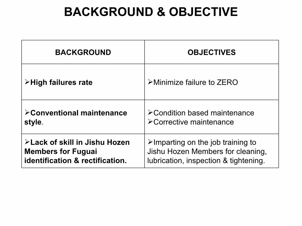
Imparting on the job training to Jishu Hozen Members for cleaning, lubrication, inspection & tightening.
Lack of skill in Jishu Hozen Members for Fuguai identification & rectification.
Condition based maintenance Corrective maintenance
Conventional maintenance style.
Minimize failure to ZEROHigh failures rate
OBJECTIVESBACKGROUND
BACKGROUND & OBJECTIVE
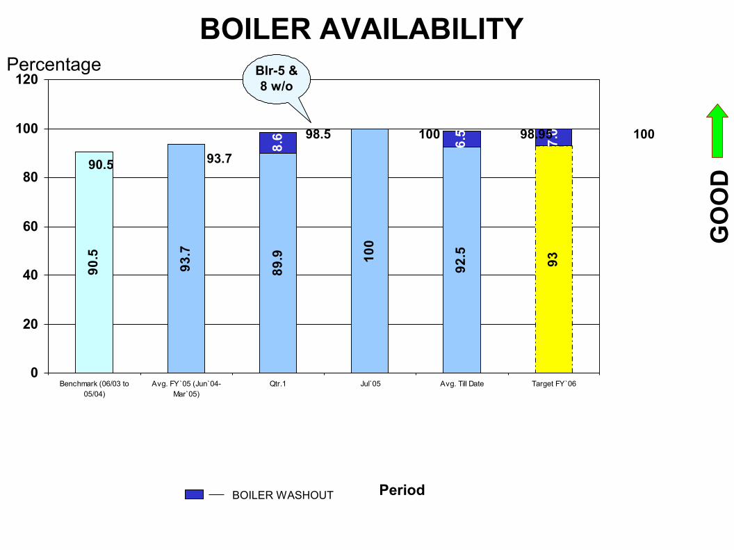
BOILER AVAILABILITY
GO
OD
90.5
93.7
89.9 10
0
92.5 93
8.6 6.5
7.0
0
20
40
60
80
100
120
Benchmark (06/03 to05/04)
Avg. FY`05 (Jun`04-Mar`05)
Qtr.1 Jul 05 Avg. Till Date Target FY`06
90.5 93.7
98.5 98.95 100
Blr-5 & 8 w/o
BOILER WASHOUT
Percentage
100
Period
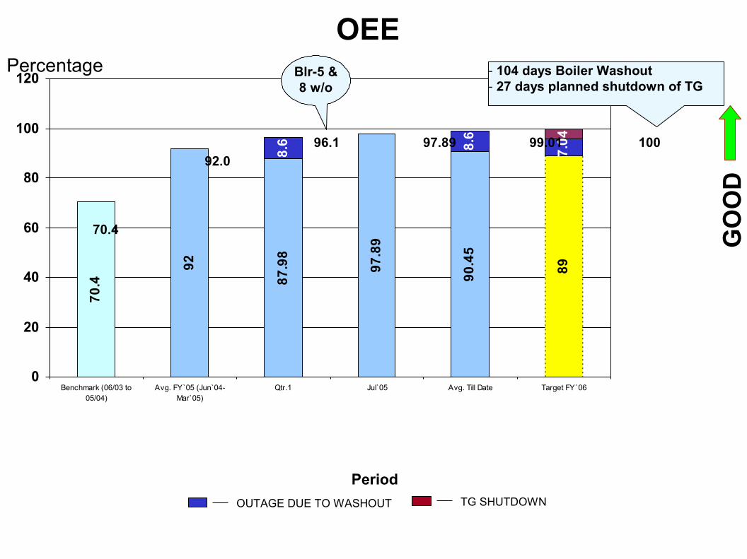
OEE
GO
OD
70.4
92
87.9
8
97.8
9
90.4
5
89
8.6 8.6
7.04
0
20
40
60
80
100
120
Benchmark (06/03 to05/04)
Avg. FY`05 (Jun`04-Mar`05)
Qtr.1 Jul 05 Avg. Till Date Target FY`06
70.4
92.096.1 97.89 99.01 100
Blr-5 & 8 w/o
OUTAGE DUE TO WASHOUT
Percentage - 104 days Boiler Washout- 27 days planned shutdown of TG
TG SHUTDOWN
Period

RESULT
As a result of the above steps oil consumption in the
Turbo Generators was come down to about 20 to 25%.
Mainly due to reduction in online filter jamming and
cleaning. Each time when we clean this filter about 25
litres of oil is getting drained out. It is totally a loss.
Back
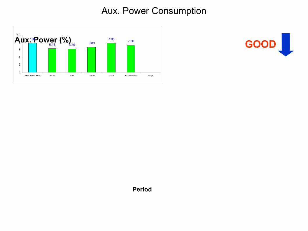
Aux. Power Consumption
7.90
6.43 6.35 6.837.88 7.36
0
2
4
6
8
10
BENCHMARK FY`03 FY`04 FY`05 Q!FY06 Jul -05 FY`06 Ti l l date Tar get
GOOD
Period
Aux. Power (%)
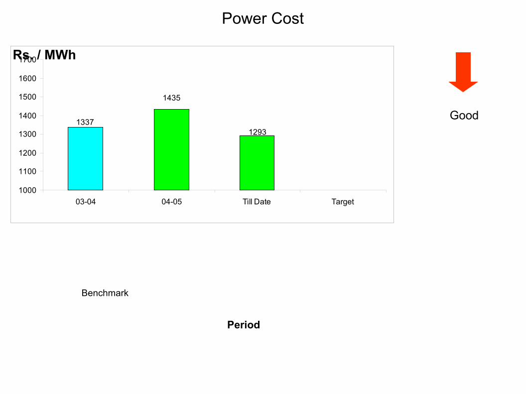
Power Cost
1293
1435
1337
1000
1100
1200
1300
1400
1500
1600
1700
03-04 04-05 Till Date Target
Rs. / MWh
Good
Period
Benchmark
• Completion of JH Step # 4
• Completion of first cycle of training as per skill
gap
matrix.
• Reduction in Oil consumption.
• Sustain the higher operational performance.
• To Focus on MTTR
TPM – Present Focus