transformer limited fault trv - ieee · tutorial cigre wg a3-28_tlf -p 4 • severe trv conditions...
TRANSCRIPT

Transformer Limited Fault TRVTransformer Limited Fault TRV
Denis Dufournet (Alstom Grid) – Anton Janssen (Liander)
(Convenor & Secretary of CIGRE WG A3-28)
GRIDTutorial made at the IEEE Switchgear Committee Meeting in San Diego (USA), on October 4th, 2012.

Tutorial CIGRE WG A3-28_TLF - P 2
1. Introduction on Transformer Limited Fault (TLF)
2. Options for the specification of TLF in IEEE C37.011-2011
3. Transformer natural frequency and Model
4. Surge capacitance of a transformer & TRV from FRA
measurements
5. Influence of external capacitances between circuit breaker and transformer
6. TLF TRV peak (kp, amplitude factor, voltage drop ratio)
7. Standardization of TLF for UHV in IEC 62271-100
8. Conclusion
9. Annexes
10. Bibliography
Content

1 1 -- IntroductionIntroduction
Tutorial CIGRE WG A3-28_TLF - P 4
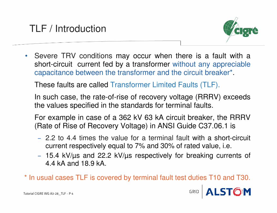
• Severe TRV conditions may occur when there is a fault with a short-circuit current fed by a transformer without any appreciable capacitance between the transformer and the circuit breaker*.
These faults are called Transformer Limited Faults (TLF).
In such case, the rate-of-rise of recovery voltage (RRRV) exceeds the values specified in the standards for terminal faults.
For example in case of a 362 kV 63 kA circuit breaker, the RRRV (Rate of Rise of Recovery Voltage) in ANSI Guide C37.06.1 is
− 2.2 to 4.4 times the value for a terminal fault with a short-circuit current respectively equal to 7% and 30% of rated value, i.e.
− 15.4 kV/µs and 22.2 kV/µs respectively for breaking currents of 4.4 kA and 18.9 kA.
TLF / Introduction
* In usual cases TLF is covered by terminal fault test duties T10 and T30.

Tutorial CIGRE WG A3-28_TLF - P 5
• In Standards or Guides, the TLF duty covers two cases
TLF / Introduction

2 2 -- Options for the Specification of Options for the Specification of
TLF in IEEE C37.011TLF in IEEE C37.011--20112011

Tutorial CIGRE WG A3-28_TLF - P 7
• As explained in IEEE C37.011-2011 (Guide for the Application of TRV for AC High-Voltage Circuit Breakers), the user has several basic possibilities
1. Specify a fast TRV for TLF with values taken from standards or guides (e.g. ANSI C37.06.1),
2. Specify a TRV calculated for the actual application taking into account
− the natural frequency of the transformer,
− and/or (depending on the knowledge of system parameters) additional capacitances present in the substation, sum of stray capacitance, busbar, CVT etc
3. Add a capacitor to reduce the RRRV
TLF / Options for Specification

Tutorial CIGRE WG A3-28_TLF - P 8
• Option 1: Specify a fast TRV for TLF with values taken from Guides (e.g. ANSI C37.06.1)
− ANSI Guide C37.06.1 is assumed to cover the large majority of all cases for this switching duty.
− TLF TRVs are given for two fault currents: 7% and 30% of rated short-circuit current.
− They are based on the assumption of a negligible capacitance between the circuit breaker and the transformer.
TLF / Options for Specification

Tutorial CIGRE WG A3-28_TLF - P 9
• Option 1 (Cont’d): TRV values in ANSI C37.06.1
TLF / Options for Specification

Tutorial CIGRE WG A3-28_TLF - P 10
TLF / Options for Specification
• Explanation on TRV value in ANSI C37.06.1
Case: Ur = 362 kV , Isc= 63 kA, ITLF = 7% Isc
− Load voltage at the time of interruption
− TRV peak (neglecting the contribution on the supply side)
with kpp = 1.5 (assumed in ANSI C37.06.1) and kaf = 1.8
393.022 r
ppafloadafc
UkkUkU ××××=××=
( )SCSSCLSS IXIXXU ×=×+= 07.0
SL XX 93.007.0 = SL XX07.0
93.0=
SSCSSCLload UIXIXU 93.093.007.0 ==×=
kVU c 7423
3625.193.028.1 =×××=
Us
Xs XL
Reactance
transformer
Reactance
supply
Uload

Tutorial CIGRE WG A3-28_TLF - P 11
• Option 1 (Cont’d): TRV values in ANSI C37.06.1
TLF / Options for Specification
Ur Ur sqrt(2/3) kp kaf kvd Calculated Uc ANSI C37.06.1
rated voltagesystem peak
phase-ground voltagepole-to-clear factor amplitude factor
voltage drop
across transformerTRV peak TRV peak
kV kV pu pu pu kV kV
123 100,4 1,5 1,8 0,93 252,2 253
145 118,4 1,5 1,8 0,93 297,3 299
170 138,8 1,5 1,8 0,93 348,5 350
Calculation TLF TRV peak - Case 7% rated short-circuit current

Tutorial CIGRE WG A3-28_TLF - P 12
• Questions at this point
− What are the relevant factors (kp, kaf and kvd) for higher
currents (e.g. 30% Isc) ?
− What are the relevant factors for higher rated voltages (e.g.
362 kV and above) ?
• Answers from CIGRE WG A3-28 will be given in section 6.
TLF / Options for Specification
Note:
kp is the pole to clear factor (for any pole)
kpp is the first pole to clear factor

Tutorial CIGRE WG A3-28_TLF - P 13
• Option 1 (Cont’d)
− As indicated in ANSI/IEEE Std C37.016-2006, time t3 is given by the following equation:
where Ur is the rated voltage in kV, C is equal to the lumped equivalent terminal capacitance to ground of the transformer in pF, and ITLF is equal to the transformer-limited fault current in kA.
C = 1480 + 89 ITLF (pF) for rated voltages less than 123 kV
C = 1650 + 180 ITLF (pF) for rated voltages 123 kV and above
− For Ur ≥ 123 kV, time t3 can be also expressed as follows:
TLF / Options for Specification
TLF
r
I
CUt
×= 106.03
21.03
18.3
TLF
r
I
Ut
×=
t3 decreases (and RRRV increases)
when the fault current increases.
Tutorial CIGRE WG A3-28_TLF - P 14
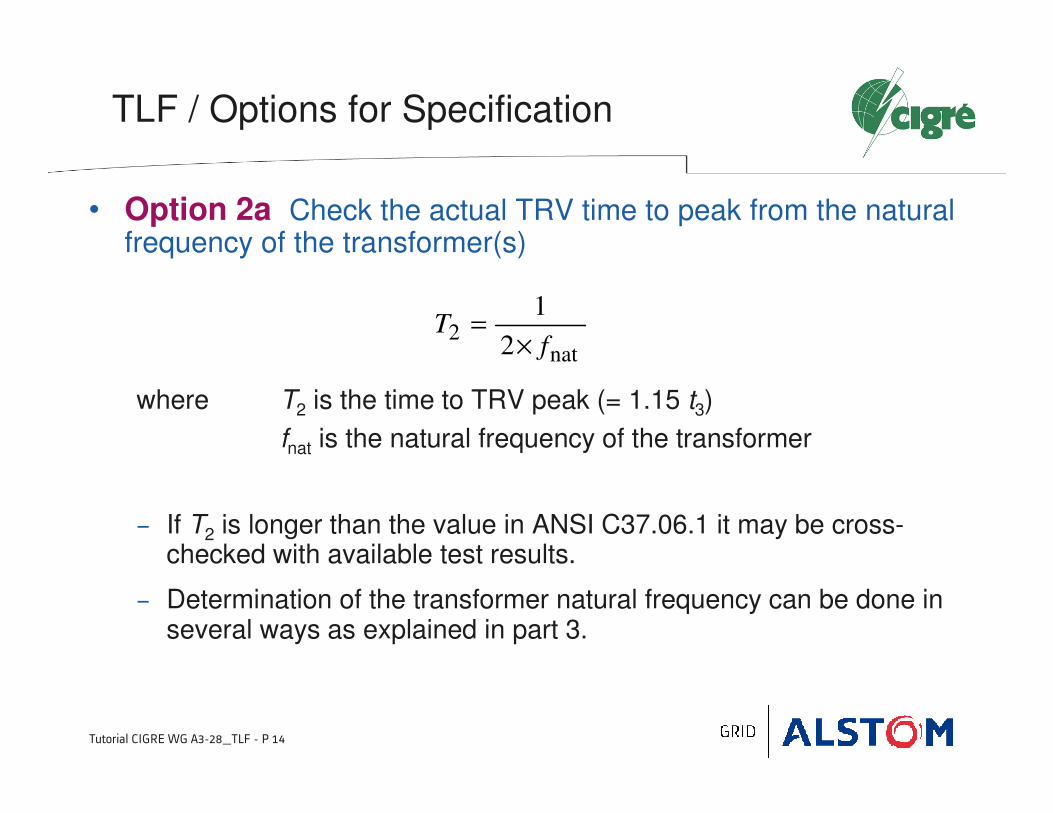
• Option 2a Check the actual TRV time to peak from the natural frequency of the transformer(s)
where T2 is the time to TRV peak (= 1.15 t3)
fnat is the natural frequency of the transformer
− If T2 is longer than the value in ANSI C37.06.1 it may be cross-checked with available test results.
− Determination of the transformer natural frequency can be done in several ways as explained in part 3.
TLF / Options for Specification
nat2
2
1
fT
×=

Tutorial CIGRE WG A3-28_TLF - P 15
• Option 2b TRV calculation for a given application
− Calculate the TRV for the given application, taking into accountadditional available capacitances or additional added capacitances i.e. line to ground capacitors, CVT’s, grading capacitors etc.
− The additional capacitance increases the time to TRV peak (T2mod) and reduces the stress for the circuit breaker according to the following equations
where
TLF / Options for Specification
)( addnatmod2 CCLT +×= π
−×
××
×
= 12
3 sc
sc
r
pp
I
I
If
Uk
Lrπ
)/()( LTC ××=22
2nat 42 π

Tutorial CIGRE WG A3-28_TLF - P 16
• Option 2b (Cont’d)
where
kpp is the first pole to clear factor
Ur is the rated maximum voltage
Isc is the rated short circuit current
I is the transformer limited fault current
fr is the power frequency
L is the equivalent inductance of the transformer
Cnat is the equivalent capacitance of the transformer (2/3 of the surgecapacitance in case of 3-phase ungrounded fault)
Cadd is the equivalent additional capacitance (2/3 of the capacitance added phase to ground in case of 3-phase ungrounded fault)
TLF / Options for Specification
Tutorial CIGRE WG A3-28_TLF - P 17
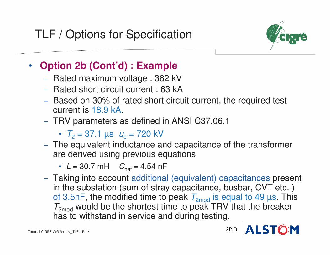
• Option 2b (Cont’d) : Example
− Rated maximum voltage : 362 kV
− Rated short circuit current : 63 kA
− Based on 30% of rated short circuit current, the required test current is 18.9 kA.
− TRV parameters as defined in ANSI C37.06.1
• T2 = 37.1 µs uc = 720 kV
− The equivalent inductance and capacitance of the transformer are derived using previous equations
• L = 30.7 mH Cnat = 4.54 nF
− Taking into account additional (equivalent) capacitances present in the substation (sum of stray capacitance, busbar, CVT etc. ) of 3.5nF, the modified time to peak T2mod is equal to 49 µs. This T2mod would be the shortest time to peak TRV that the breaker has to withstand in service and during testing.
TLF / Options for Specification

Tutorial CIGRE WG A3-28_TLF - P 18
• Option 3 Additional capacitor
− Test reports may be available for the circuit breaker showing a certain T2 value which is higher than the T2 value given in ANSI C37.06.1.
− Such a breaker could be used for this application by adding a capacitor to ground which changes the actual T2 to a value where a proof for the circuit breaker capability exists.
where T2 test value is the time to peak of tested TRV.
− If for example, a circuit breaker has been tested with a time T2 test of 70 µs, a current equal to 30 % of its rated short circuit current of 63kA and a rated maximum voltage of 362 kV, this would require an additional capacitance of 11.6 nF in order to make the breaker feasible for this application.
TLF / Options for Specification
CTL
Cnat2
2
test2add −
×=
π
3 3 -- Transformer Frequency & ModelTransformer Frequency & Model

Tutorial CIGRE WG A3-28_TLF - P 20
TLF / Transformer Frequency & Model
• The transformer frequency can be derived from measurements by
− Current injection,
− Resonant frequency measurement,
− Daini-kyodai method.
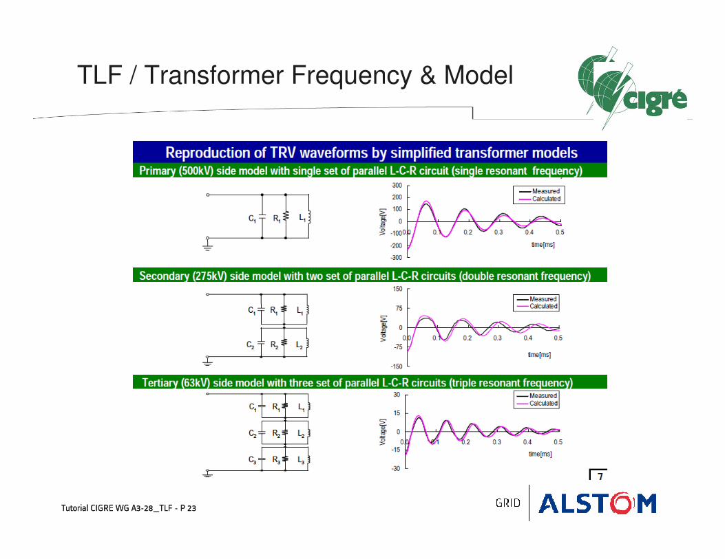
• The transient response on the transformer side is quite complicated in most cases, so that two approaches are possible:
1. A simplified model with an equivalent RLC circuit that gives the main TRV frequency and associated amplitude factor.
2. Detailed models that are able to reproduce the multi-frequency phenomena,
Examples are given in the following, taken from papers A3-107 [3] & A3-108 [4] presented at CIGRE session 2012.

Tutorial CIGRE WG A3-28_TLF - P 21
TLF / Transformer Frequency & Model
• Current injection method
− The method is described in Annex F of IEC 62271-100
− It provides the TRV for the first-pole-to-clear
− TRVs for the second and third-pole-to-clear can also measured with the core type by removing the earthing points at A or at A and B, respectively.
Determination of transformer natural frequency

Tutorial CIGRE WG A3-28_TLF - P 22
TLF / Transformer Frequency & Model
• Current injection method (Cont’d)
− Example of TRV measurement (CIGRE paper A3-108_2012)
Determination of transformer natural frequency
Tutorial CIGRE WG A3-28_TLF - P 23
TLF / Transformer Frequency & Model
Tutorial CIGRE WG A3-28_TLF - P 23

Tutorial CIGRE WG A3-28_TLF - P 24
TLF / Transformer Frequency & Model
• Resonant frequency measurement (FRA)
− Test circuit and example of measurement
Determination of transformer natural frequency
V0
V1
R Transformer(One phase)
Frequency
Generator
SeriesWinding
CommonWinding
TertiaryWinding
Tertiary
Primary
Secondary
I0

Tutorial CIGRE WG A3-28_TLF - P 25
TLF / Transformer Frequency & Model
• Daini-kyodai method
− Test circuit
Determination of transformer natural frequency
Rm
V1
Step voltage
Generator
r
Transformer
(One phase)
SeriesWinding
CommonWinding
TertiaryWinding
Tertiary
Primary
Secondary
Rm
r
Test object Oscilloscope Step voltage source
C L R
Zx
Rm >> r, Zx
Reference resistor
Constant current

Tutorial CIGRE WG A3-28_TLF - P 26
TLF / Transformer Frequency & Model
• Daini-kyodai method
− Example of measurement
Determination of transformer natural frequency

Tutorial CIGRE WG A3-28_TLF - P 27
a1
a2
t1
t2
Measured waveform for Zx
Measured waveform for r
y
a1=r ×××× y 1 /y (ΩΩΩΩ )
y1
y2
a2=r ×××× y 2 /y (ΩΩΩΩ )
TLF / Transformer Frequency & Model
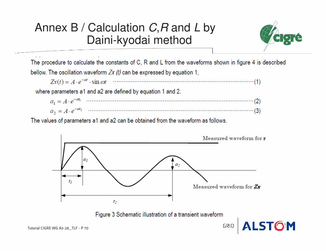
• Daini-kyodai method
The oscillation waveform of Zx directly shows the transient impedance of
the test object.
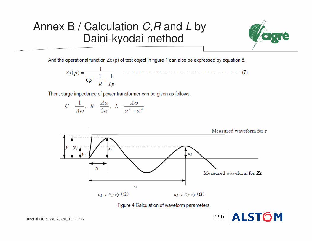
The components C, R and L of Zx can be calculated from the waveform of Zx by a comparison with the waveform obtained with r (see Annex B).
Determination of transformer natural frequency

Tutorial CIGRE WG A3-28_TLF - P 28
TLF / Transformer Frequency & Model
• Comparison of frequency measurement and Daini-kyodai method
Determination of transformer natural frequency
Tutorial CIGRE WG A3-28_TLF - P 29
TLF / Transformer Frequency & Model
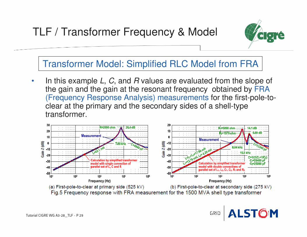
• In this example L, C, and R values are evaluated from the slope of the gain and the gain at the resonant frequency obtained by FRA (Frequency Response Analysis) measurements for the first-pole-to-clear at the primary and the secondary sides of a shell-type transformer.
Transformer Model: Simplified RLC Model from FRA

Tutorial CIGRE WG A3-28_TLF - P 30
TLF / Transformer Frequency & Model
• First example from CIGRE paper A3_108_2012 [4]
− Multi-mesh and lumped models
Transformer Model: Detailed Model

Tutorial CIGRE WG A3-28_TLF - P 31
TLF / Transformer Frequency & Model
• 2nd example from CIGRE paper A3_107_2012 [3]
− Conventional model with capacitances to earth & between windings (manufacturer model)
Transformer Model: Detailed Model
Tutorial CIGRE WG A3-28_TLF - P 32
TLF / Transformer Frequency & Model
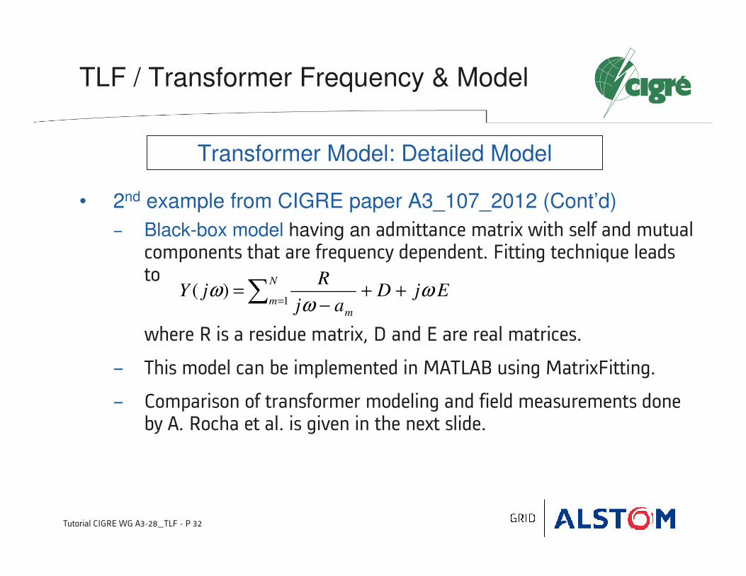
• 2nd example from CIGRE paper A3_107_2012 (Cont’d)
− Black-box model having an admittance matrix with self and mutual components that are frequency dependent. Fitting technique leadsto
where R is a residue matrix, D and E are real matrices.
− This model can be implemented in MATLAB using MatrixFitting.
− Comparison of transformer modeling and field measurements done by A. Rocha et al. is given in the next slide.
Transformer Model: Detailed Model
EjDaj
RjY
N
mm
ωω
ω ++−
=∑ =1)(

Tutorial CIGRE WG A3-28_TLF - P 33
TLF / Transformer Frequency & Model
• 2nd example from CIGRE paper A3_107_2012 (Cont’d)
− Comparison of 25 MVA single-phase transformer self-admittance and angle by black box model with rational fitting (black curve) and by field measurement (blue curve).
Transformer Model: Detailed Model

Tutorial CIGRE WG A3-28_TLF - P 34
TLF / Transformer Frequency & Model
• 2nd example from CIGRE paper A3_107_2012 (Cont’d)
− Comparison of 3-phase ungrounded transformer secondary fault TRV with conventional model (in blue) and black-box or rational fitting model (in green). Fault current is 2 kA.
Transformer Model: Detailed Model
Comparison of RRRV
9.1 kV/µs : conventional model
5.07 kV/µs : rational fitting model
Note: AS (curve in red) is another
method called asymptotic synthesis
described in the next slide, it gives an
RRRV of 5.09 kV/µs
Tutorial CIGRE WG A3-28_TLF - P 35
TLF / Transformer Frequency & Model
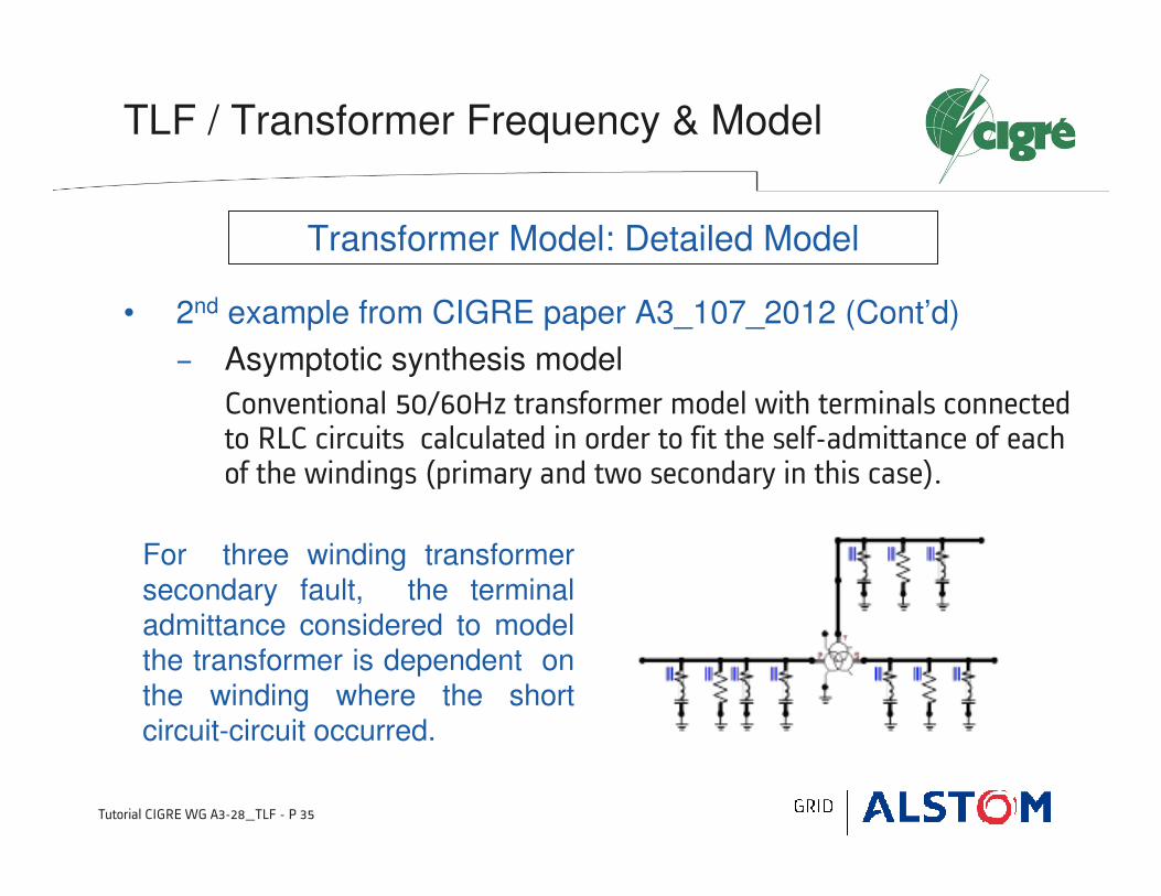
• 2nd example from CIGRE paper A3_107_2012 (Cont’d)
− Asymptotic synthesis model
Conventional 50/60Hz transformer model with terminals connected to RLC circuits calculated in order to fit the self-admittance of each of the windings (primary and two secondary in this case).
Transformer Model: Detailed Model
For three winding transformer secondary fault, the terminal admittance considered to model the transformer is dependent on the winding where the short circuit-circuit occurred.
Tutorial CIGRE WG A3-28_TLF - P 36
TLF / Transformer Frequency & Model
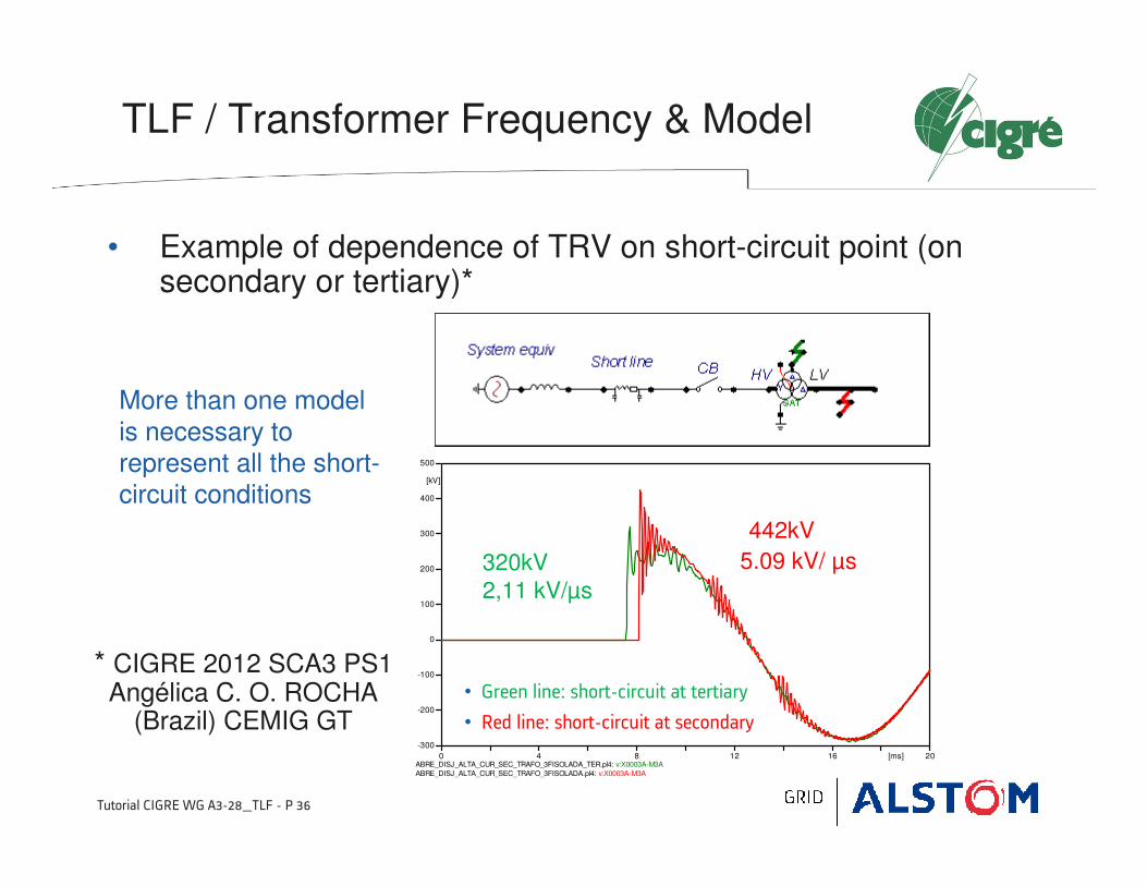
• Example of dependence of TRV on short-circuit point (on secondary or tertiary)*
ABRE_DISJ_ALTA_CUR_SEC_TRAFO_3FISOLADA_TER.pl4: v:X0003A-M3A
ABRE_DISJ_ALTA_CUR_SEC_TRAFO_3FISOLADA.pl4: v:X0003A-M3A
0 4 8 12 16 20[ms]
-300
-200
-100
0
100
200
300
400
500
[kV]
* CIGRE 2012 SCA3 PS1 Angélica C. O. ROCHA
(Brazil) CEMIG GT
442kV
5.09 kV/ µs320kV
2,11 kV/µs
• Green line: short-circuit at tertiary
• Red line: short-circuit at secondary
More than one model
is necessary to represent all the short-circuit conditions
4 4 ––Surge Capacitance of a Transformer Surge Capacitance of a Transformer
and TRV from FRA Measurementsand TRV from FRA Measurements

Tutorial CIGRE WG A3-28_TLF - P 38
101
102
103
104
105
106
107
101
102
103
104
105
106
107
Frequency [Hz]
Z [
Ohm
]
LV terminal shorted
LV
terminal
open
Tutorial CIGRE WG A3-28_TLF - P 38
TLF / Surge Capacitance of a Transformer
• From the initial part of the FRA-measurement an equivalent inductance(short-circuit inductance) can be determined, whereas in the higher frequency region (some hundreds of kHz) the surge capacitance can be approached.
• Example
80 MVA, 400 kV
L=640 mH, C=400 pF
Tutorial CIGRE WG A3-28_TLF - P 39
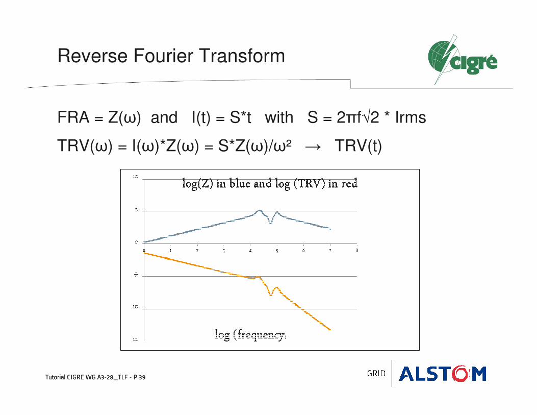
Reverse Fourier Transform
FRA = Z(ω) and I(t) = S*t with S = 2πf√2 * Irms
TRV(ω) = I(ω)*Z(ω) = S*Z(ω)/ω² → TRV(t)
Tutorial CIGRE WG A3-28_TLF - P 39

Tutorial CIGRE WG A3-28_TLF - P 40
Examples TRV from FRA-measurements (KEMA HPL)
Tutorial CIGRE WG A3-28_TLF - P 40
Tutorial CIGRE WG A3-28_TLF - P 41
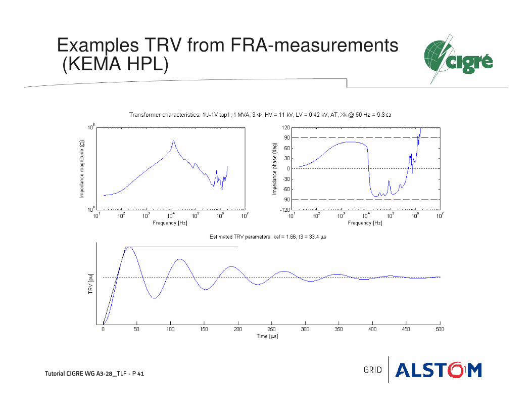
Examples TRV from FRA-measurements(KEMA HPL)
Tutorial CIGRE WG A3-28_TLF - P 41

Tutorial CIGRE WG A3-28_TLF - P 42
Examples TRV from FRA-measurements(KEMA HPL)
Tutorial CIGRE WG A3-28_TLF - P 42

Tutorial CIGRE WG A3-28_TLF - P 43
Examples TRV from FRA-measurements(KEMA HPL)
Tutorial CIGRE WG A3-28_TLF - P 43

Tutorial CIGRE WG A3-28_TLF - P 44
Examples TRV from FRA-measurements (KEMA HPL)
Tutorial CIGRE WG A3-28_TLF - P 44

Tutorial CIGRE WG A3-28_TLF - P 45
Examples TRV from FRA-measurements (KEMA HPL)
Tutorial CIGRE WG A3-28_TLF - P 45

Tutorial CIGRE WG A3-28_TLF - P 46
Examples TRV from FRA-measurements (KEMA HPL)
Tutorial CIGRE WG A3-28_TLF - P 46

Tutorial CIGRE WG A3-28_TLF - P 47
Comparison with single frequency model
Based on short-circuit inductance and surge capacitance
2-parameter TRV values
Tutorial CIGRE WG A3-28_TLF - P 47
Case 4 Case 8 Case 9 Case 10 Case 11 Case 12
KEMA* t3 (µs) 39.2 61.1 33.4 64.6 50.5 46.3
Simple t3 (µs) 43.5 53.0 35.0 49.0 56.5 33.5
KEMA* AF 1.75 1.69 1.66 1.65 1.54 1.71
Simple AF 1.80 1.84 1.74 1.80 1.78 1.78
KEMA* kV/µs 44.6 27.7 49.7 25.5 30.5 36.9
Simple kV/µs 41.4 34.7 49.7 36.7 31.6 53.1
KEMA*: from reverse Fourier transformSimple: from LCR parallel circuit

5 5 –– Influence of External Capacitances Influence of External Capacitances
Between Circuit Breaker & TransformerBetween Circuit Breaker & Transformer

Tutorial CIGRE WG A3-28_TLF - P 49
Influence of external capacitance
Tutorial CIGRE WG A3-28_TLF - P 49

Tutorial CIGRE WG A3-28_TLF - P 50
TLF / Additional Capacitances
Capacitance according to IEEE C37.011-2011
• Busbar for air-insulated bus: 8.2-18.0 pF/m.
• Surge arrester 80-120 pF
• CT / VT
− the capacitance of an outdoor current transformer is: 150–450 pF
− the capacitance of an outdoor potential transformer is: 150–450 pF
• CVT
2 000–6 200800
1 500–6 300550
2 150–9 500362
3 000–12 500245
4 000-16 500170
4 000–22 000145
Capacitance
(pF)
Voltage class
(kV)

Tutorial CIGRE WG A3-28_TLF - P 51
TLF / Additional Capacitances
• Example of connection between circuit breaker and transformer: Hydro Quebec 735kV side of transformer

Tutorial CIGRE WG A3-28_TLF - P 52
TLF / Additional Capacitances
• Example of connection between circuit breaker and transformer: Hydro Quebec 230kV side of transformer
MOSA
transformer DS DS
CB
6 6 –– TLF TRV Peak FactorsTLF TRV Peak Factors
PolePole--toto--clear factor, Amplitude Factor clear factor, Amplitude Factor
& Voltage Drop Ratio& Voltage Drop Ratio

Tutorial CIGRE WG A3-28_TLF - P 54
TLF TRV Peak / Pole-to-clear factor
• The TRV peak is function of 3 factors as shown in the following equation
kp = pole-to-clear factor, kaf = amplitude factor, kvd= voltage drop across the transformer
• Pole-to-clear factor
− On the EHV or UHV side, the transformer neutral is effectively grounded,
as a consequence, pole-to-clear factors are between 1.0 and 1.15 (see calculation in Annex).
− A conservative value could be taken as equal to 1.3.
3
2rvdafpc
UkkkU ×××=
Tutorial CIGRE WG A3-28_TLF - P 55
TLF / TRV Amplitude Factor
• From the initial part of the FRA-measurement an equivalent inductance can be determined. In the higher frequency region (some hundreds of kHz) the equivalent capacitance can be approached.
• From these two values (L and C) both a single frequency can be determined and an equivalent value Z.
• The ratio between the highest peak of the FRA-impedance measurement and this value Z determines the amplitude factor.
• A ratio R/Z of 5, as found in a case studied by WG A3-28, gives an amplitude factor of 1.73.
• In CIGRE paper A3-108-2012, values of amplitudes factors are equal or lower than 1.62.

Tutorial CIGRE WG A3-28_TLF - P 56
Damping or Amplitude factorSingle frequency model
Alan Greenwood’s: Electrical Transients in Power Systems, 2nd
Tutorial CIGRE WG A3-28_TLF - P 56

Tutorial CIGRE WG A3-28_TLF - P 57
TLF / Voltage Drop Ratio
• In IEC & IEEE standards, the voltage drop ratio is assumed to be 0.9 for terminal fault test duty T10.
• The voltage drop ratio is function of the ratio of TLF current (Ip-TLF) and
the bus short-circuit current minus the contribution from the faulted
transformer (Ip-net)
Considering the circuit breaker at the primary side, the voltage drop in case of transformer secondary fault (TSF) is
netp
TLFp
I
IV
−
−−=∆ 1

Tutorial CIGRE WG A3-28_TLF - P 58
TLF / Voltage Drop Ratio
• Based on the previous equation, the voltage drop can be expressed as function of the ratio TLF fault current divided by rated short-circuit current (in percentage) assuming different possible values of the bus short-circuit current
ITLF in % of rated short-circuit current Isc
Voltage
drop in %
Tutorial CIGRE WG A3-28_TLF - P 59
TLF / Voltage Drop Ratio
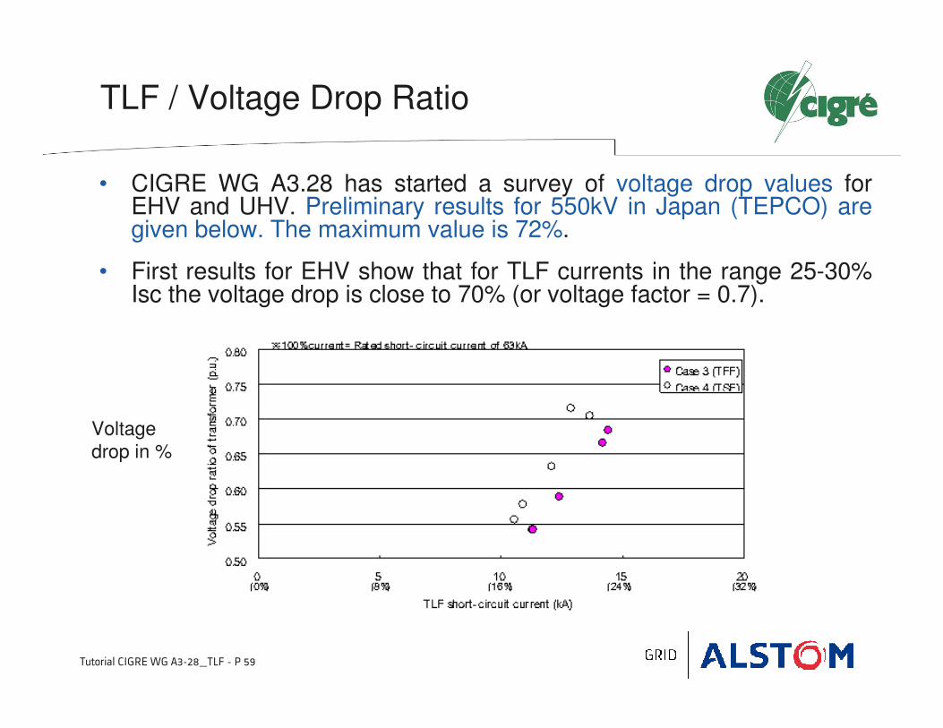
• CIGRE WG A3.28 has started a survey of voltage drop values for EHV and UHV. Preliminary results for 550kV in Japan (TEPCO) are given below. The maximum value is 72%.
• First results for EHV show that for TLF currents in the range 25-30% Isc the voltage drop is close to 70% (or voltage factor = 0.7).
Voltage
drop in %

7 7 –– Standardization of TLF Standardization of TLF
for UHV in IEC 62271for UHV in IEC 62271--100100
Tutorial CIGRE WG A3-28_TLF - P 61
• Transformer limited fault (TLF) is covered in Annex M.
• M.4 is for rated voltages higher than 800kV
− The system TRV can be modified by a capacitance and then be within the standard TRV capability envelope. As an alternative, the user can choose to specify a rated transformer limited fault (TLF) current breaking capability.
− The rated TLF breaking current is selected from the R10 series in order to limit the number of testing values possible. Preferred values are 10 kA and 12,5 kA.
− TRV parameters are calculated from the TLF current, the rated voltage and a capacitance of the transformer and liaison of 9 nF.
− The first-pole-to clear- factor corresponding to this type of fault is 1,2. Pending further studies, conservative values are taken for the amplitude factor and the voltage drop across the transformer. They are respectively equal to 1,7 and 0,9.
Standardization of TLF for UHVin IEC 62271-100
Tutorial CIGRE WG A3-28_TLF - P 62
Standardization of TLF for UHV in IEC 62271-100
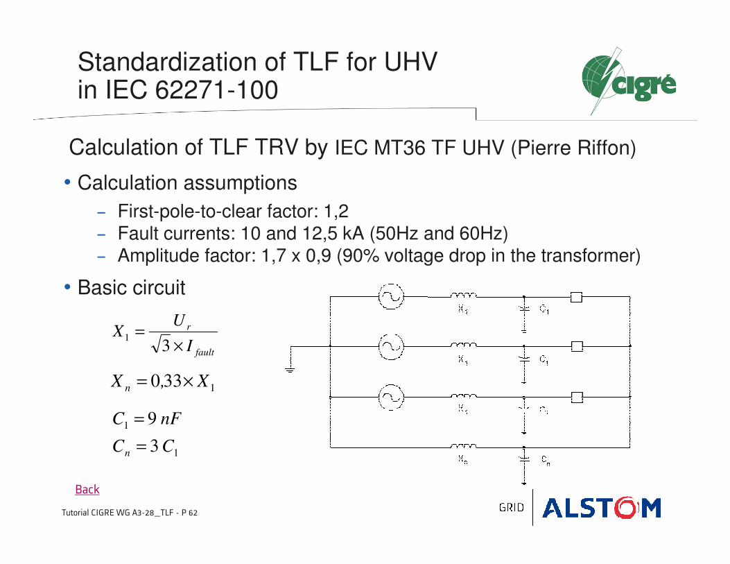
Calculation of TLF TRV by IEC MT36 TF UHV (Pierre Riffon)
• Calculation assumptions
− First-pole-to-clear factor: 1,2− Fault currents: 10 and 12,5 kA (50Hz and 60Hz)− Amplitude factor: 1,7 x 0,9 (90% voltage drop in the transformer)
• Basic circuit
Back
fault
r
I
UX
×=
31
1330 X,X n ×=
1
1
3
9
CC
nFC
n =
=
Tutorial CIGRE WG A3-28_TLF - P 63
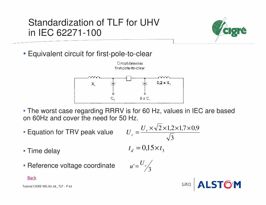
Standardization of TLF for UHV in IEC 62271-100
• Equivalent circuit for first-pole-to-clear
• The worst case regarding RRRV is for 60 Hz, values in IEC are based on 60Hz and cover the need for 50 Hz.
• Equation for TRV peak value
• Time delay
• Reference voltage coordinate
Back
3
9071212 ,,,UU r
c
××××=
3150 t,td ×=
3cU
'u =

Tutorial CIGRE WG A3-28_TLF - P 64
Standardization of TLF for UHV in IEC 62271-100
• Reference time coordinate
• TRV Table
dtRRRV'u't +=
8 8 -- ConclusionConclusion

Tutorial CIGRE WG A3-28_TLF - P 66
Conclusion
• Transformer-limited-faults produce fast TRVs with a high RRRV if there is a low capacitance between the transformer and the circuit-breaker.
• For this duty, it is important to properly evaluate the capacitance (frequency) of the transformer and the capacitance of the liaison between the circuit breaker and the transformer.
• Several methods were presented for the evaluation of a transformer surge capacitance/ TRV frequency: by current injection or from FRA measurements.
• RRRV is also function of the TRV peak, as it is the ratio of theTRV peak by the time to peak (related to the TRV frequency).
• TRV peak is function of several factors (pole-to-clear, amplitude factor, voltage drop across transformer) that must be properly chosen in standards.
9 9 -- AnnexesAnnexes
Annex A - Calculation of kpp for TLF
Annex B - Calculation C, R and L by Daini-kyodai method

Tutorial CIGRE WG A3-28_TLF - P 68
Annex A / Calculation of kpp for TLF
Case: Three-phase to ground fault
Tutorial CIGRE WG A3-28_TLF - P 69
Annex A / Calculation of kpp for TLF
• First-pole-to-clear factor for 3-phase to ground faults
− First-pole-to-clear factor for TLF was evaluated in case of a power transformer with delta connection for tertiary winding providinglower voltage networks with short-circuit power of 50kA (system
with effectively-grounded neutral).
− The study shows that
• kpp for a primary fault is lower than 1.15
• kpp for a secondary fault is lower than 0.95.
Tutorial CIGRE WG A3-28_TLF - P 70
Annex B / Calculation C,R and L by Daini-kyodai method

Tutorial CIGRE WG A3-28_TLF - P 71
Annex B / Calculation C,R and L by Daini-kyodai method
(see Figure 4)
Tutorial CIGRE WG A3-28_TLF - P 72
Annex B / Calculation C,R and L by Daini-kyodai method
10 10 -- BibliographyBibliography

Tutorial CIGRE WG A3-28_TLF - P 74
Bibliography
1. R.H. Harner, J. Rodriguez, “Transient Recovery Voltages Associated with Power-System, Three-Phase Transformer Secondary Faults”, IEEE Transactions, vol. PAS-91, pp. 1887–1896 (1972-09/10).
2. A. Morched, L. Marti, J. Oevangera, “A High Frequency Transformer Model for the EMTP”, IEEE Transactions on Power Delivery, Vol. 8, N°3 (1993-07)
3. M. Steurer, W. Hribernik, J. Brunke. “Calculating the TRV Associated with Clearing Transformer Determined Faults by Means of Frequency Response Analysis ”, IEEE Transactions on Power Delivery, vol. 19, N°1 (2004-01).
4. A.C.O. Rocha, G.H.C. Oliveira, R.M. Azevedo, A.C.S. Lima, “ Assessment of Transformer Modeling Impact on Transient Recovery Voltage in Transformer Limited Faults ”, Paper A3-107, CIGRE Session 2012
5. Y. Yamagata, M. Kosakada, H. Ito et al., “Considerations on Transformer Limited Fault duty for GCB in UHV and EHV networks with large capacity power transformers ”, Paper A3-108, CIGRE Session 2012.
6. R. Horton, R. Dugan, K. Wallace, D. Hallmark, “Improved Autotransformer Model for Transient Recovery Voltage (TRV Studies) ”, IEEE Transactions on Power Delivery, Vol. 27, N°2 (2012-04)

Thank you for your attentionThank you for your attention
Questions ?Questions ?
Thanks to Members of CIGRE WG A3-28 for their input and to Dr Hiroki Ito (Chairman of CIGRE SC A3).
Skyline of Downtown San Diego by Wikipedia / J.Dewes