transient simulation of a rotating conducting …simulate the magnetic field inside a rotating solid...
TRANSCRIPT
UNCLASSIFIED
UNCLASSIFIED
AD-E403 795
Technical Report ARMET-TR-15078
TRANSIENT SIMULATION OF A ROTATING CONDUCTING CYLINDER IN A TRANSVERSE MAGNETIC FIELD
Jyeching Lee Shana Groeschler
September 2016
Approved for public release; distribution is unlimited.
AD
U.S. ARMY ARMAMENT RESEARCH, DEVELOPMENT AND ENGINEERING CENTER
Munitions Engineering Technology Center
Picatinny Arsenal, New Jersey
UNCLASSIFIED
UNCLASSIFIED
The views, opinions, and/or findings contained in this report are those of the author(s) and should not be construed as an official Department of the Army position, policy, or decision, unless so designated by other documentation. The citation in this report of the names of commercial firms or commercially available products or services does not constitute official endorsement by or approval of the U.S. Government. Destroy this report when no longer needed by any method that will prevent disclosure of its contents or reconstruction of the document. Do not return to the originator.
UNCLASSIFIED
UNCLASSIFIED
REPORT DOCUMENTATION PAGE Form Approved OMB No. 0704-01-0188
The public reporting burden for this collection of information is estimated to average 1 hour per response, including the time for reviewing instructions, searching existing data sources, gathering and maintaining the data needed, and completing and reviewing the collection of information. Send comments regarding this burden estimate or any other aspect of this collection of information, including suggestions for reducing the burden to Department of Defense, Washington Headquarters Services Directorate for Information Operations and Reports (0704-0188), 1215 Jefferson Davis Highway, Suite 1204, Arlington, VA 22202-4302. Respondents should be aware that notwithstanding any other provision of law, no person shall be subject to any penalty for failing to comply with a collection of information if it does not display a currently valid OMB control number. PLEASE DO NOT RETURN YOUR FORM TO THE ABOVE ADDRESS.
1. REPORT DATE (DD-MM-YYYY)
September 2016 2. REPORT TYPE
Final 3. DATES COVERED (From – To)
4. TITLE AND SUBTITLE
TRANSIENT SIMULATION OF A ROTATING CONDUCTING CYLINDER IN A TRANSVERSE MAGNETIC FIELD
5a. CONTRACT NUMBER
5b. GRANT NUMBER
5c. PROGRAM ELEMENT NUMBER
6. AUTHORS
Jyeching Lee and Shana Groeschler
5d. PROJECT NUMBER
5e. TASK NUMBER
5f. WORK UNIT NUMBER
7. PERFORMING ORGANIZATION NAME(S) AND ADDRESS(ES)
U.S. Army ARDEC, METC Fuze & Precision Armaments Technology Directorate (RDAR-MEF-E) Picatinny Arsenal, NJ 07806-5000
8. PERFORMING ORGANIZATION REPORT NUMBER
9. SPONSORING/MONITORING AGENCY NAME(S) AND ADDRESS(ES)
U.S. Army ARDEC, ESIC Knowledge & Process Management (RDAR-EIK) Picatinny Arsenal, NJ 07806-5000
10. SPONSOR/MONITOR’S ACRONYM(S)
11. SPONSOR/MONITOR’S REPORT NUMBER(S)
Technical Report ARMET-TR-15078 12. DISTRIBUTION/AVAILABILITY STATEMENT
Approved for public release; distribution is unlimited. 13. SUPPLEMENTARY NOTES
14. ABSTRACT
As military projectiles become more sophisticated, equipped with a variety of electronic devices used during flight, the environmental and structural factors that can affect the accuracy of the internal electronic components need to be continuously examined. When a magnetometer is used in a spinning projectile with a metallic envelope, both the direction and magnitude of the magnetic field vector detected within the projectile are affected by the spinning of the projectile. To study this, transient finite element analyses were conducted to simulate the magnetic field inside a rotating solid conducting cylinder immersed in a uniform transverse magnetic field, such as earth’s magnetic field. The factors that affect the magnetic field inside the cylinder were analyzed by varying the spin rate and the electromagnetic physical properties (conductivity and permeability) of the cylinder. The magnetometer was assumed to be at the center of the cylinder’s axis of rotation for this analysis. Therefore, the magnitude and direction (phase shift angle) of the magnetic flux density vector at the center of the cylinder’s axis of rotation were evaluated. The analysis results indicated that the magnetic field inside the cylinder was affected by the spin rate and the electromagnetic properties of the cylinder. The phenomenon due to the eddy current and skin effect on the magnetic field distribution inside the cylinder was demonstrated. 15. SUBJECT TERMS
Magnetic field Magnetic flux Magnetometer Eddy currents Skin effect Finite element method 16. SECURITY CLASSIFICATION OF: 17. LIMITATION OF
ABSTRACT
SAR
18. NUMBER OF PAGES
31
19a. NAME OF RESPONSIBLE PERSON
Jyeching Lee a. REPORT
U b. ABSTRACT
U c. THIS PAGE
U 19b. TELEPHONE NUMBER (Include area
code) (973) 724-2490
Standard Form 298 (Rev. 8/98) Prescribed by ANSI Std. Z39.18

UNCLASSIFIED
Approved for public release; distribution is unlimited.
UNCLASSIFIED i
CONTENTS
Page Introduction 1
The Finite Element Model 2
Analysis Results 3
Stage 1 - Verification of Finite Element Method 4 Stage 2 - Parametrical Sweep, Electrical Conductivity 6 Stage 3 - Parametric Sweep, Magnetic Permeability 14
Conclusions 20
References 23
Distribution List 25
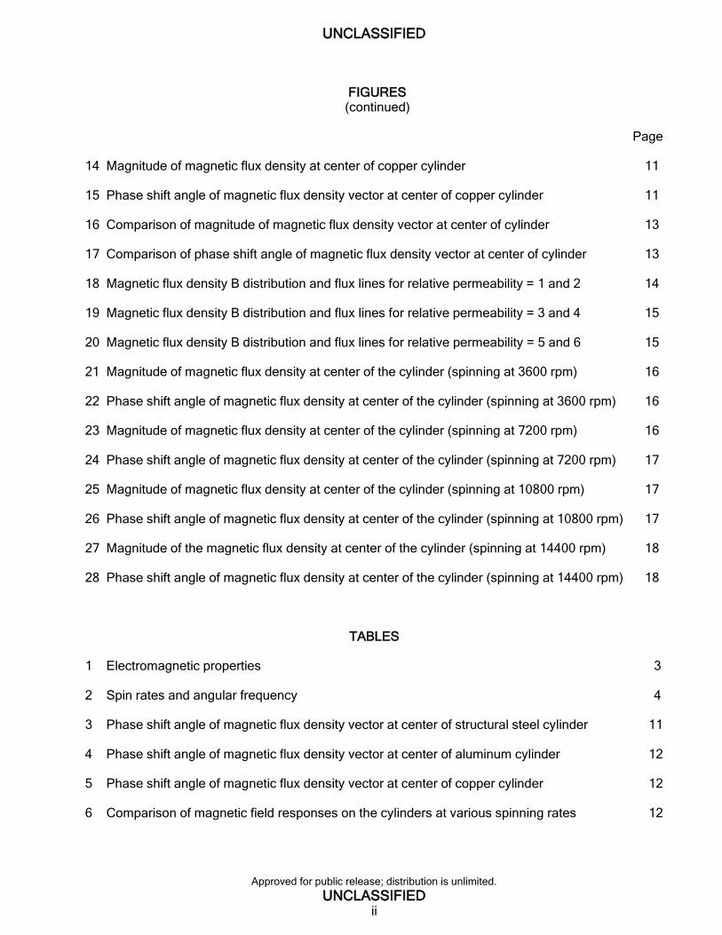
FIGURES
1 Model of boundary conditions and magnetic field excitations 3
2 Magnitude of magnetic flux density at center of cylinder of relative permeability 1.0 5
3 Magnitude of magnetic flux density at center of the cylinder of relative permeability 1000 5
4 Magnetic flux lines for the cylinder of relative permeability 1.0 6
5 Magnetic flux lines for the cylinder of relative permeability 1000 6
6 Phase shift angle and position of magnetic flux density vector 7
7 Magnetic flux density B distribution and flux lines for structural steel cylinder case 8
8 Magnetic flux density B distribution and flux lines for aluminum cylinder case 8
9 Magnetic flux density B distribution and flux lines for copper cylinder case 8
10 Magnitude of magnetic flux density at center of structural steel cylinder 9
11 Phase shift angle of magnetic flux density vector at center of structural steel cylinder 9
12 Magnitude of magnetic flux density at center of aluminum cylinder 10
13 Phase shift angle of magnetic flux density vector at center of aluminum cylinder 10
UNCLASSIFIED
Approved for public release; distribution is unlimited.
UNCLASSIFIED ii
FIGURES (continued)
Page
14 Magnitude of magnetic flux density at center of copper cylinder 11
15 Phase shift angle of magnetic flux density vector at center of copper cylinder 11
16 Comparison of magnitude of magnetic flux density vector at center of cylinder 13
17 Comparison of phase shift angle of magnetic flux density vector at center of cylinder 13
18 Magnetic flux density B distribution and flux lines for relative permeability = 1 and 2 14
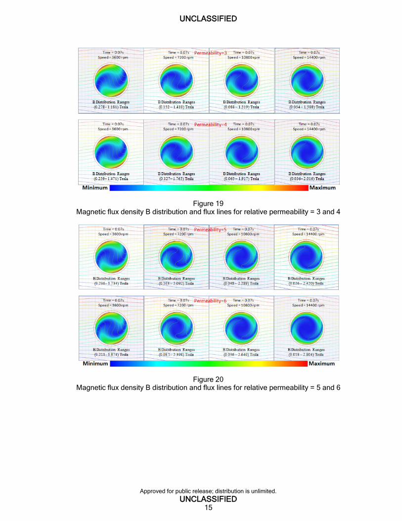
19 Magnetic flux density B distribution and flux lines for relative permeability = 3 and 4 15
20 Magnetic flux density B distribution and flux lines for relative permeability = 5 and 6 15
21 Magnitude of magnetic flux density at center of the cylinder (spinning at 3600 rpm) 16
22 Phase shift angle of magnetic flux density at center of the cylinder (spinning at 3600 rpm) 16
23 Magnitude of magnetic flux density at center of the cylinder (spinning at 7200 rpm) 16
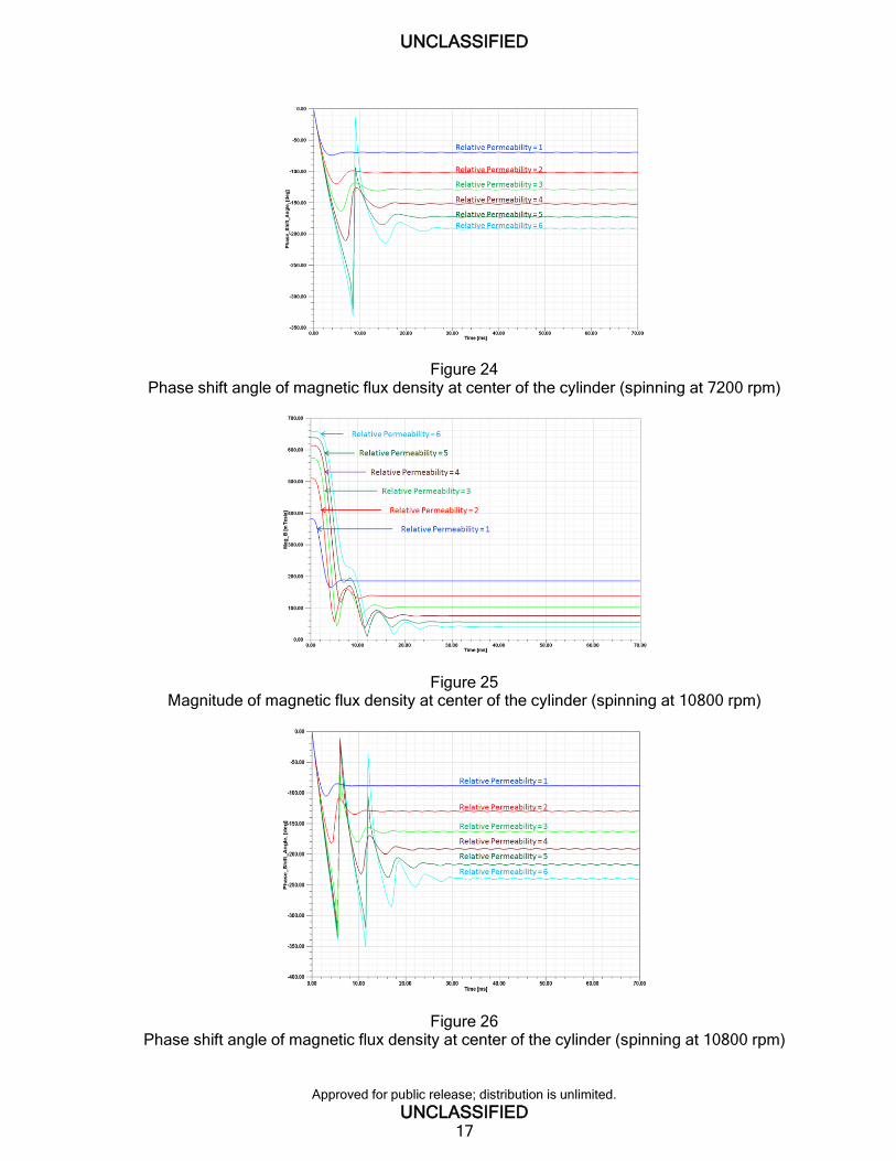
24 Phase shift angle of magnetic flux density at center of the cylinder (spinning at 7200 rpm) 17
25 Magnitude of magnetic flux density at center of the cylinder (spinning at 10800 rpm) 17
26 Phase shift angle of magnetic flux density at center of the cylinder (spinning at 10800 rpm) 17
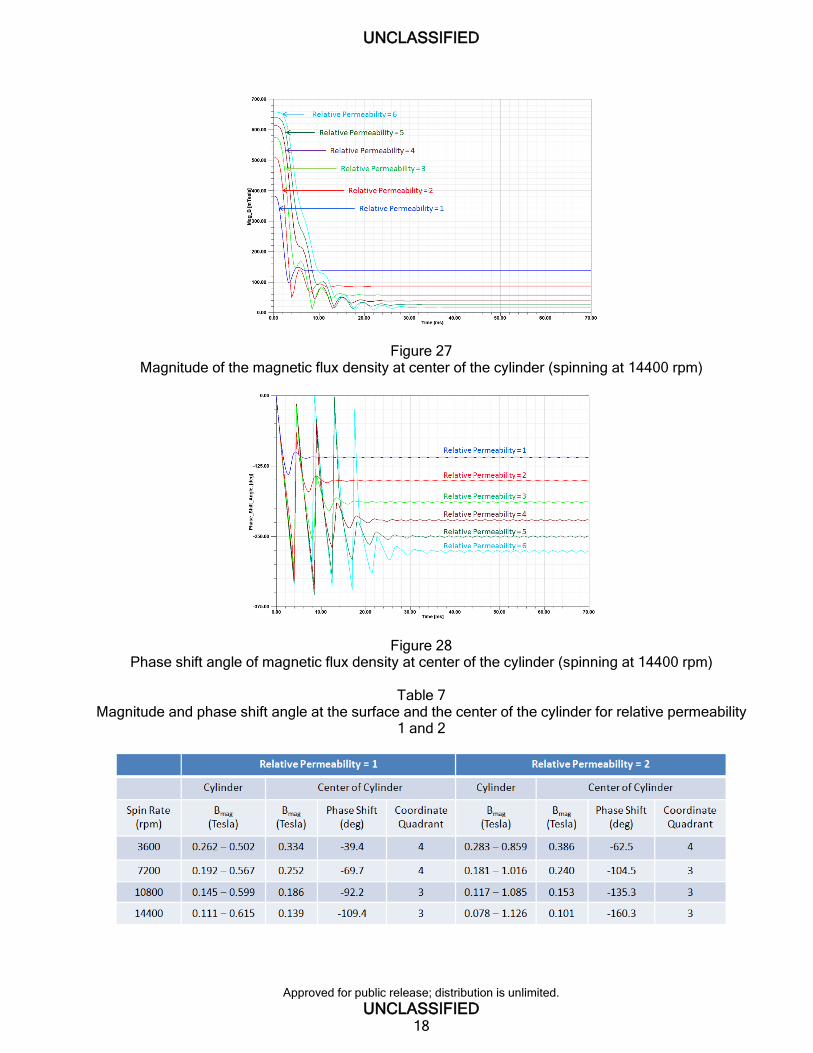
27 Magnitude of the magnetic flux density at center of the cylinder (spinning at 14400 rpm) 18
28 Phase shift angle of magnetic flux density at center of the cylinder (spinning at 14400 rpm) 18
TABLES 1 Electromagnetic properties 3
2 Spin rates and angular frequency 4
3 Phase shift angle of magnetic flux density vector at center of structural steel cylinder 11
4 Phase shift angle of magnetic flux density vector at center of aluminum cylinder 12
5 Phase shift angle of magnetic flux density vector at center of copper cylinder 12
6 Comparison of magnetic field responses on the cylinders at various spinning rates 12
UNCLASSIFIED
Approved for public release; distribution is unlimited.
UNCLASSIFIED iii
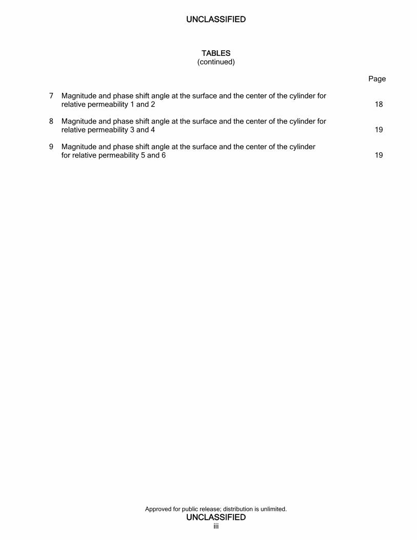
TABLES (continued)
Page 7 Magnitude and phase shift angle at the surface and the center of the cylinder for
relative permeability 1 and 2 18 8 Magnitude and phase shift angle at the surface and the center of the cylinder for
relative permeability 3 and 4 19 9 Magnitude and phase shift angle at the surface and the center of the cylinder
for relative permeability 5 and 6 19

UNCLASSIFIED
Approved for public release; distribution is unlimited.
UNCLASSIFIED 1
INTRODUCTION Electronic devices, such as for sensing and navigation, are becoming more common within military projectiles. Modeling and simulation may be useful to understand the electromagnetic effects caused by a spinning metal projectile flying though a magnetic field and help minimize unfavorable aspects of these effects on the electronic devices contained inside the round. These effects include induced (eddy) currents and changes in magnetic flux. The eddy current is generated within a conductor when the conductor moves relative to a stationary magnetic field, such as the earth’s magnetic field. The eddy current is also induced within the conductor when an alternating external magnetic field is applied to the conductor. The eddy current produces the magnetic field, which opposes the change in magnetic flux that induces such currents, so the total magnetic flux is reduced. The skin effect occurs due to the opposing eddy current induced by the changing magnetic field from the alternating current. The skin effect is the tendency of high frequency current and magnetic flux to concentrate near the outer edge, or surface, of a conductor, instead of flowing uniformly over the entire cross-sectional area of the conductor, and then to decay toward the center. The higher the spin rate, the more pronounced the skin effect.
This eddy current behavior can be analyzed by using Ampѐre’s equation (refs. 1 and 2) and Bullard’s equation as shown. Ampѐre’s equation.
𝜎𝜕��
𝜕𝑡+ ∇ × (
��
𝜇) − 𝜎�� × �� = 𝐽�� (1)
If there is no external current density, 𝐽�� = 0, Ampѐre’s equation can be reduced to Bullard’s equation (ref. 3):
𝜕��
𝜕𝑡−
∇2��
𝜇𝜎− ∇ × (�� × ��) = 0 (2)
- Conductivity, Siemens/meter (S/m)
𝐴 - Magnetic vector potential, Weber/meter (Wb/m)
�� - Magnetic flux density, tesla (T)
�� - Velocity, meter/second (m/s) or
- Angular velocity, radian/second (rad/s) or revolutions per minute (rpm)
0 - Permeability for free space, 4 x 10⁻⁷ Henry/meter (H/m)
r - Relative permeability of the medium
- Permeability of the medium, = 0 x r (H/m)
𝐽�� - External current density, Ampѐre/meter (A/m)
Both equations (Ampѐre and Bullard) show that the magnetic flux density is a function of
velocity, conductivity, and permeability, �� = ��(�� , 𝜎, 𝜇). A closed-form solution (ref. 3) and a finite
element analysis [FEA, (ref. 4)] in the steady state condition (𝐽�� = 0, 𝜕𝐵/𝜕𝑡 = 0), were performed to determine the effects on the magnetic field distribution inside and outside a rotating solid conducting cylinder (hereafter called cylinder) immersed in a uniform transverse magnetic field by varying the
spin rate (rpm) and electromagnetic physical properties [conductivity () and permeability ()] of the cylinder. Similar studies were conducted by various authors using the analytical method (refs. 5 and 6) and finite element modeling techniques (refs. 7 and 8). Two-dimensional (2D) finite element time-dependent transient analyses of an infinitely long cylinder were modeled using the ANSYS Maxwell program. A magnetometer, which is an electronic
UNCLASSIFIED
Approved for public release; distribution is unlimited.
UNCLASSIFIED 2
sensor used to measure the magnitude and direction (angle) of a magnetic field, was placed at the center of the cylinder’s axis of rotation for this analysis and was modeled as a nodal point. Two magnets (NdFe35) were used to generate a magnetic field around the cylinder. The dynamic (time dependent) behaviors of the eddy current interaction between the conductor and magnetic field excitation were studied. The magnetic flux density vector at the center of the cylinder’s axis of rotation was evaluated. The factors that may affect the eddy current interactions and magnetic field responses were analyzed by varying the spin rate and the electromagnetic properties (conductivity and permeability) of the cylinder. The analyses were done in three stages.
Verify the accuracy of the transient analysis by comparing the results to the analytical closed-form solution (ref. 3) and a FEA (ref. 4) at a steady-state condition.
Compare the magnitude and phase shift angles of the magnetic flux density at the center of the cylinder for three different conductive materials at various spin rates (3600, 7200, 10800, and 14400 rpm). The phase shift angle is the variation between the initial (0 deg, t = 0) angle and the angle affected by the spin rate and/or physical materials of the cylinder.
Conduct a parametric study by varying the permeability and the spin rate of the cylinder for a specific conductive material.
THE FINITE ELEMENT MODEL
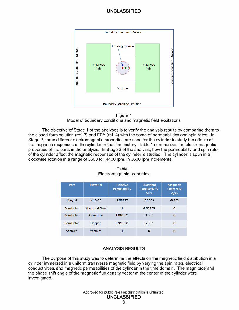
The cylinder and magnetic poles are assumed to be infinitely long with uniform cross sections. The external magnetic field is transverse to the cylinder and there is no induced B (magnetic flux density) in the direction normal to the plane of the cross section. The field patterns in the entire device can be analyzed by modeling the field patterns in its cross section. Therefore, a 2D finite element model is used for the analysis. Figure 1 shows the boundary conditions and magnetic field excitation. The balloon (no fringing at infinity) boundary condition is used for the model. Two magnetic poles are used to generate a constant magnetic field for the cylinder at the center location. The moving objects are separated from stationary objects. The center region of the geometry, defined as a band (moving) object, contains the cylinder and part of the air gap and rotates relative to the global fixed coordinate system of the magnetic poles. The band object is decoupled from the magnetic poles, and the surrounding air and the regions are meshed independently. This is done so the center can freely rotate since otherwise the mesh definitions would be violated by the rotation of the cylinder.
UNCLASSIFIED
Approved for public release; distribution is unlimited.
UNCLASSIFIED 3
Figure 1 Model of boundary conditions and magnetic field excitations
The objective of Stage 1 of the analyses is to verify the analysis results by comparing them to
the closed-form solution (ref. 3) and FEA (ref. 4) with the same of permeabilities and spin rates. In Stage 2, three different electromagnetic properties are used for the cylinder to study the effects of the magnetic responses of the cylinder in the time history. Table 1 summarizes the electromagnetic properties of the parts in the analysis. In Stage 3 of the analysis, how the permeability and spin rate of the cylinder affect the magnetic responses of the cylinder is studied. The cylinder is spun in a clockwise rotation in a range of 3600 to 14400 rpm, in 3600 rpm increments.
Table 1
Electromagnetic properties
ANALYSIS RESULTS The purpose of this study was to determine the effects on the magnetic field distribution in a cylinder immersed in a uniform transverse magnetic field by varying the spin rates, electrical conductivities, and magnetic permeabilities of the cylinder in the time domain. The magnitude and the phase shift angle of the magnetic flux density vector at the center of the cylinder were investigated.
UNCLASSIFIED
Approved for public release; distribution is unlimited.
UNCLASSIFIED 4
Stage 1 - Verification of Finite Element Method In order to verify the finite element model, analyses were performed using these parameters and compared to the closed-form solutions (ref. 3) and FEA results (ref. 4).
The relative permeability of the cylinder - one and 1000.
The conductivity of cylinder - 3.774E7 S/m (aluminum).
Magnetic Reynolds number, equation 3 - five and 25.
𝑅𝑚 = 𝑅2 ⁄ (3)
Angular velocity can be determined from equation 4.
= 𝑅2 𝑅𝑚𝜇𝜎⁄ (4)
Rm - Magnetic Reynolds number R - Radius of rotating cylinder, meter
- Angular velocity, rad/s or rpm
Spin rate (rpm) and angular (rotational) frequency (Hz) are shown in table 2.
Table 2
Spin rates and angular frequency
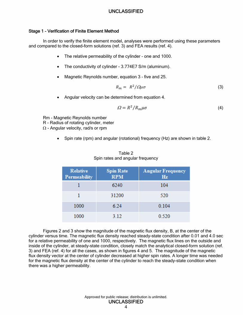
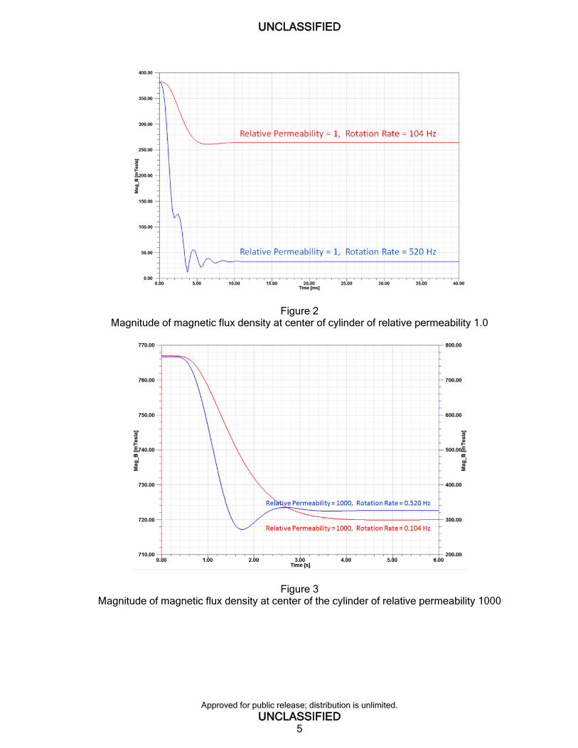
Figures 2 and 3 show the magnitude of the magnetic flux density, B, at the center of the cylinder versus time. The magnetic flux density reached steady-state condition after 0.01 and 4.0 sec for a relative permeability of one and 1000, respectively. The magnetic flux lines on the outside and inside of the cylinder, at steady-state condition, closely match the analytical closed-form solution (ref. 3) and FEA (ref. 4) for all the cases, as shown in figures 4 and 5. The magnitude of the magnetic flux density vector at the center of cylinder decreased at higher spin rates. A longer time was needed for the magnetic flux density at the center of the cylinder to reach the steady-state condition when there was a higher permeability.
UNCLASSIFIED
Approved for public release; distribution is unlimited.
UNCLASSIFIED 5
Figure 2 Magnitude of magnetic flux density at center of cylinder of relative permeability 1.0
Figure 3 Magnitude of magnetic flux density at center of the cylinder of relative permeability 1000
UNCLASSIFIED
Approved for public release; distribution is unlimited.
UNCLASSIFIED 6
Figure 4 Magnetic flux lines for the cylinder of relative permeability 1.0
Figure 5 Magnetic flux lines for the cylinder of relative permeability 1000
Stage 2 - Parametrical Sweep, Electrical Conductivity Three different conductive materials (structural steel, aluminum, and copper) were chosen to study the effects of the electromagnetic responses of the cylinder. These three materials have the same values for permeability and permittivity except they have different electrical conductivities as shown in table 1. Transient analyses were performed to determine the effect of conductivity on the
UNCLASSIFIED
Approved for public release; distribution is unlimited.
UNCLASSIFIED 7
magnitude and the phase shift angle of the magnetic flux density vector at the center of the cylinder and the magnetic field distribution inside the cylinder in time domain. The cylinder was spun in a clockwise rotation in a range of 3600 to 14400 rpm, in 3600 rpm increments.
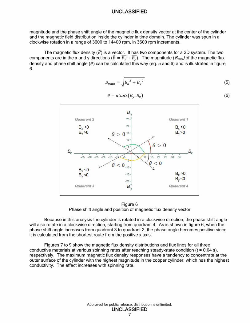
The magnetic flux density (��) is a vector. It has two components for a 2D system. The two
components are in the x and y directions (�� = 𝐵𝑥 + 𝐵𝑦
). The magnitude (Bmag) of the magnetic flux
density and phase shift angle (𝜃) can be calculated this way (eq. 5 and 6) and is illustrated in figure 6.
𝐵𝑚𝑎𝑔 = √𝐵𝑥2 + 𝐵𝑦
2 (5)
𝜃 = 𝑎𝑡𝑎𝑛2(𝐵𝑦, 𝐵𝑥) (6)
Figure 6 Phase shift angle and position of magnetic flux density vector
Because in this analysis the cylinder is rotated in a clockwise direction, the phase shift angle will also rotate in a clockwise direction, starting from quadrant 4. As is shown in figure 6, when the phase shift angle increases from quadrant 3 to quadrant 2, the phase angle becomes positive since it is calculated from the shortest route from the positive x axis.
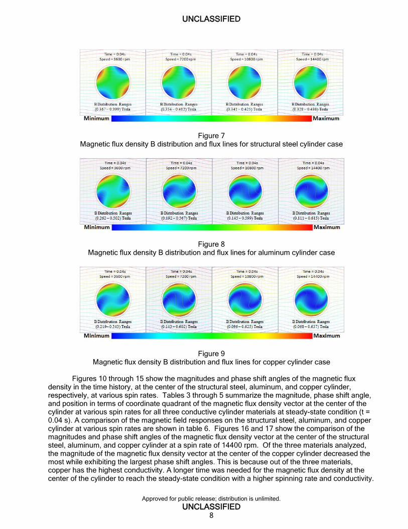
Figures 7 to 9 show the magnetic flux density distributions and flux lines for all three conductive materials at various spinning rates after reaching steady-state condition (t = 0.04 s), respectively. The maximum magnetic flux density responses have a tendency to concentrate at the outer surface of the cylinder with the highest magnitude in the copper cylinder, which has the highest conductivity. The effect increases with spinning rate.
UNCLASSIFIED
Approved for public release; distribution is unlimited.
UNCLASSIFIED 8
Figure 7 Magnetic flux density B distribution and flux lines for structural steel cylinder case
Figure 8 Magnetic flux density B distribution and flux lines for aluminum cylinder case
Figure 9 Magnetic flux density B distribution and flux lines for copper cylinder case
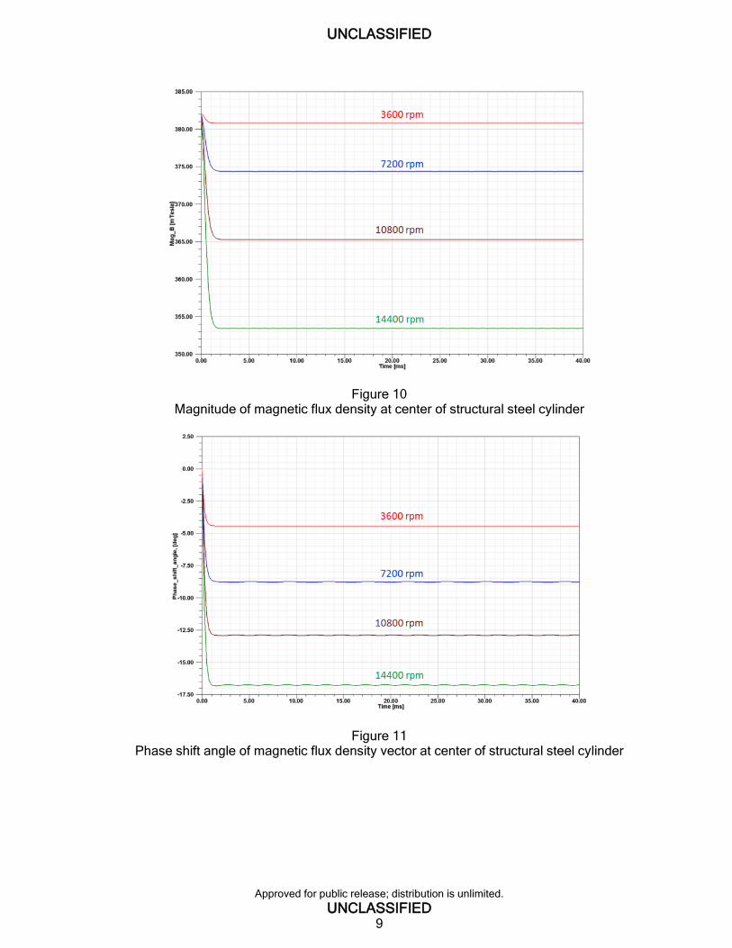
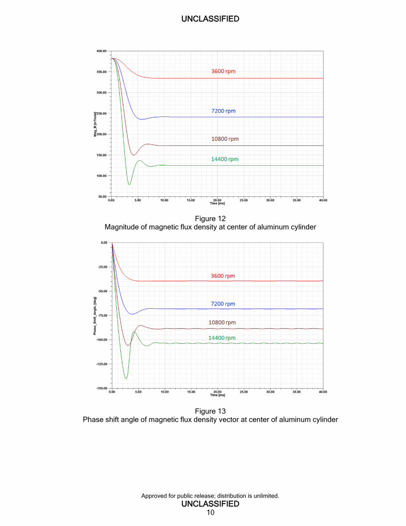
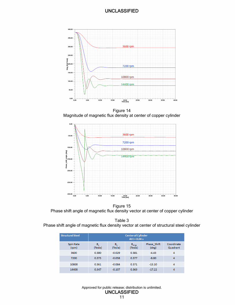
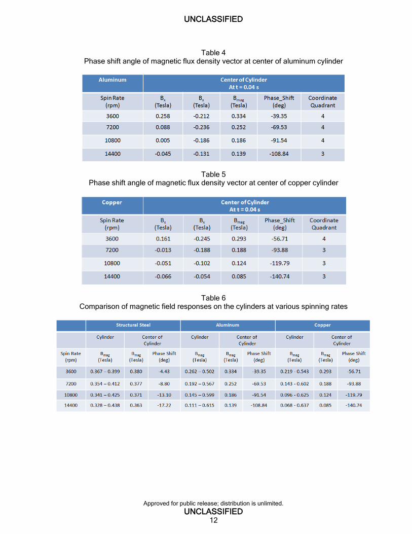
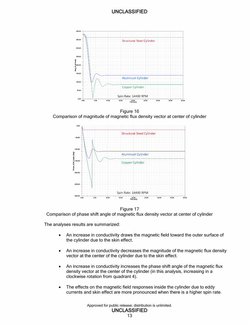
Figures 10 through 15 show the magnitudes and phase shift angles of the magnetic flux density in the time history, at the center of the structural steel, aluminum, and copper cylinder, respectively, at various spin rates. Tables 3 through 5 summarize the magnitude, phase shift angle, and position in terms of coordinate quadrant of the magnetic flux density vector at the center of the cylinder at various spin rates for all three conductive cylinder materials at steady-state condition (t = 0.04 s). A comparison of the magnetic field responses on the structural steel, aluminum, and copper cylinder at various spin rates are shown in table 6. Figures 16 and 17 show the comparison of the magnitudes and phase shift angles of the magnetic flux density vector at the center of the structural steel, aluminum, and copper cylinder at a spin rate of 14400 rpm. Of the three materials analyzed, the magnitude of the magnetic flux density vector at the center of the copper cylinder decreased the most while exhibiting the largest phase shift angles. This is because out of the three materials, copper has the highest conductivity. A longer time was needed for the magnetic flux density at the center of the cylinder to reach the steady-state condition with a higher spinning rate and conductivity.
UNCLASSIFIED
Approved for public release; distribution is unlimited.
UNCLASSIFIED 9
Figure 10 Magnitude of magnetic flux density at center of structural steel cylinder
Figure 11 Phase shift angle of magnetic flux density vector at center of structural steel cylinder
UNCLASSIFIED
Approved for public release; distribution is unlimited.
UNCLASSIFIED 10
Figure 12 Magnitude of magnetic flux density at center of aluminum cylinder
Figure 13 Phase shift angle of magnetic flux density vector at center of aluminum cylinder
UNCLASSIFIED
Approved for public release; distribution is unlimited.
UNCLASSIFIED 11
Figure 14 Magnitude of magnetic flux density at center of copper cylinder
Figure 15 Phase shift angle of magnetic flux density vector at center of copper cylinder
Table 3
Phase shift angle of magnetic flux density vector at center of structural steel cylinder
UNCLASSIFIED
Approved for public release; distribution is unlimited.
UNCLASSIFIED 12
Table 4 Phase shift angle of magnetic flux density vector at center of aluminum cylinder
Table 5 Phase shift angle of magnetic flux density vector at center of copper cylinder
Table 6 Comparison of magnetic field responses on the cylinders at various spinning rates
UNCLASSIFIED
Approved for public release; distribution is unlimited.
UNCLASSIFIED 13
Figure 16 Comparison of magnitude of magnetic flux density vector at center of cylinder
Figure 17 Comparison of phase shift angle of magnetic flux density vector at center of cylinder
The analyses results are summarized:
An increase in conductivity draws the magnetic field toward the outer surface of the cylinder due to the skin effect.
An increase in conductivity decreases the magnitude of the magnetic flux density vector at the center of the cylinder due to the skin effect.
An increase in conductivity increases the phase shift angle of the magnetic flux density vector at the center of the cylinder (in this analysis, increasing in a clockwise rotation from quadrant 4).
The effects on the magnetic field responses inside the cylinder due to eddy currents and skin effect are more pronounced when there is a higher spin rate.
UNCLASSIFIED
Approved for public release; distribution is unlimited.
UNCLASSIFIED 14
A longer time was needed for the magnetic flux density at the center of the cylinder to reach the steady-state condition for higher spinning rate and conductivity.
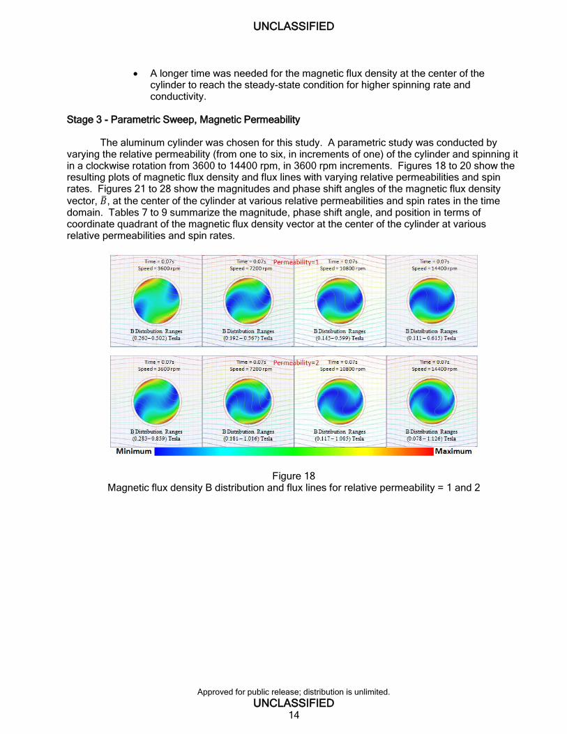
Stage 3 - Parametric Sweep, Magnetic Permeability The aluminum cylinder was chosen for this study. A parametric study was conducted by varying the relative permeability (from one to six, in increments of one) of the cylinder and spinning it in a clockwise rotation from 3600 to 14400 rpm, in 3600 rpm increments. Figures 18 to 20 show the resulting plots of magnetic flux density and flux lines with varying relative permeabilities and spin rates. Figures 21 to 28 show the magnitudes and phase shift angles of the magnetic flux density
vector, ��, at the center of the cylinder at various relative permeabilities and spin rates in the time domain. Tables 7 to 9 summarize the magnitude, phase shift angle, and position in terms of coordinate quadrant of the magnetic flux density vector at the center of the cylinder at various relative permeabilities and spin rates.
Figure 18 Magnetic flux density B distribution and flux lines for relative permeability = 1 and 2
UNCLASSIFIED
Approved for public release; distribution is unlimited.
UNCLASSIFIED 15
Figure 19 Magnetic flux density B distribution and flux lines for relative permeability = 3 and 4
Figure 20 Magnetic flux density B distribution and flux lines for relative permeability = 5 and 6

UNCLASSIFIED
Approved for public release; distribution is unlimited.
UNCLASSIFIED 16
Figure 21 Magnitude of magnetic flux density at center of the cylinder (spinning at 3600 rpm)
Figure 22 Phase shift angle of magnetic flux density at center of the cylinder (spinning at 3600 rpm)
Figure 23 Magnitude of magnetic flux density at center of the cylinder (spinning at 7200 rpm)
UNCLASSIFIED
Approved for public release; distribution is unlimited.
UNCLASSIFIED 17
Figure 24 Phase shift angle of magnetic flux density at center of the cylinder (spinning at 7200 rpm)
Figure 25 Magnitude of magnetic flux density at center of the cylinder (spinning at 10800 rpm)
Figure 26 Phase shift angle of magnetic flux density at center of the cylinder (spinning at 10800 rpm)
UNCLASSIFIED
Approved for public release; distribution is unlimited.
UNCLASSIFIED 18
Figure 27 Magnitude of the magnetic flux density at center of the cylinder (spinning at 14400 rpm)
Figure 28 Phase shift angle of magnetic flux density at center of the cylinder (spinning at 14400 rpm)
Table 7
Magnitude and phase shift angle at the surface and the center of the cylinder for relative permeability 1 and 2
UNCLASSIFIED
Approved for public release; distribution is unlimited.
UNCLASSIFIED 19
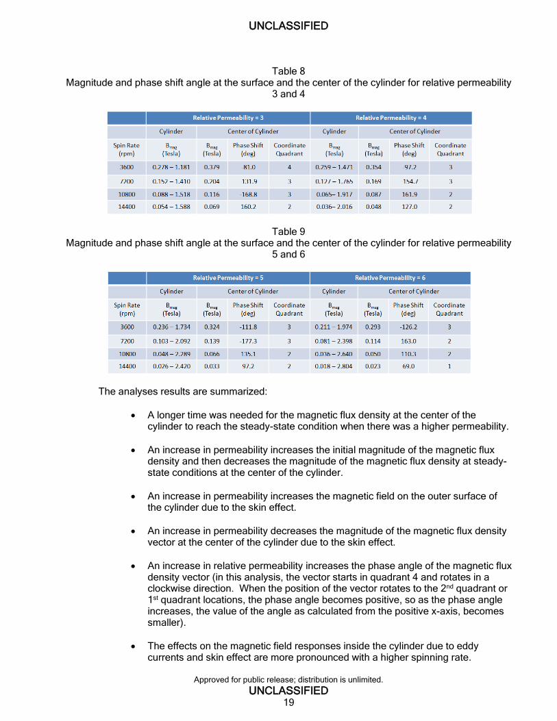
Table 8 Magnitude and phase shift angle at the surface and the center of the cylinder for relative permeability
3 and 4
Table 9 Magnitude and phase shift angle at the surface and the center of the cylinder for relative permeability
5 and 6
The analyses results are summarized:
A longer time was needed for the magnetic flux density at the center of the cylinder to reach the steady-state condition when there was a higher permeability.
An increase in permeability increases the initial magnitude of the magnetic flux density and then decreases the magnitude of the magnetic flux density at steady-state conditions at the center of the cylinder.
An increase in permeability increases the magnetic field on the outer surface of the cylinder due to the skin effect.
An increase in permeability decreases the magnitude of the magnetic flux density vector at the center of the cylinder due to the skin effect.
An increase in relative permeability increases the phase angle of the magnetic flux density vector (in this analysis, the vector starts in quadrant 4 and rotates in a clockwise direction. When the position of the vector rotates to the 2nd quadrant or 1st quadrant locations, the phase angle becomes positive, so as the phase angle increases, the value of the angle as calculated from the positive x-axis, becomes smaller).
The effects on the magnetic field responses inside the cylinder due to eddy currents and skin effect are more pronounced with a higher spinning rate.
UNCLASSIFIED
Approved for public release; distribution is unlimited.
UNCLASSIFIED 20
CONCLUSIONS
The electromagnetic analysis of a rotating conducting cylinder in a magnetic field was evaluated by comparing the analysis results to the closed form solution and verifying that the solutions from both methods closely match each other, as seen by comparing the resulting magnetic flux lines on the cylinder. In addition, a parametric study was performed using a finite element method solver to assess the factors that affect the magnetic field distribution on the cylinder by varying the magnetic material properties (conductivity and permeability) and angular velocity. The magnitude and phase angle of the magnetic flux density vector at the center of the cylinder was investigated. Bullard’s equation states that the magnetic flux density is proportional to the conductivity, velocity, and permeability. The results from the parametric study show that the magnitude and phase angle of the magnetic field vector were affected by the angular velocity and the electromagnetic properties of the cylinder. The analyses results also show that the magnetic field responses on the cylinder exhibit the phenomenon of eddy current and the skin effect.
The eddy currents produce a magnetic flux which tends to oppose the change in magnetic flux that induces such currents, so the total magnetic flux is reduced.
The higher the conductivity, the larger the eddy currents are, and the larger the permeability or the higher the rotational frequency, the more pronounced is the magnetic flux reduction.
The skin effect is the tendency of high frequency current and magnetic flux to concentrate near the outer edge, or surface, of a conductor and then to decay toward the center.
The higher the rotational frequency, the larger the magnetic flux at the outer surface of the cylinder.
The higher the rotational frequency, the lower the magnetic flux at the center of the cylinder.
An increase in permeability, conductivity, and rotational frequency produces a larger phase angle of the magnetic flux density vector at the center of the cylinder.
An increase in permeability, conductivity, and rotational frequency increases the time needed for the magnetic flux density at the center of the cylinder to reach the steady-state condition. However, the time needed to reach the steady-state condition is almost instantaneous, and the magnetic field responses during that transient period may be disregarded.
The magnetic field density and phase shift angle at the center of the cylinder oscillate at double the rotational frequency. This doubling of the frequency was seen in the model because the model included two magnetic poles. In reality, where an electrical field is generated by the earth, we are not certain how the rotational frequency will be affected. At higher permeability and faster spin rates, the amplitude of the oscillating increases and is more pronounced.
Transient finite element modeling has been shown to be capable of capturing
electromagnetic effects caused by a spinning cylinder within a magnetic field, such as earth’s magnetic field. Changes in the magnetic field due to eddy currents and skin effects were seen in relation to angular velocity and material properties. As electronic devices such as sensors and

UNCLASSIFIED
Approved for public release; distribution is unlimited.
UNCLASSIFIED 21
navigation equipment become more widespread within spinning projectiles, the ability to model and analyze the magnetic field generated during flight, due to eddy currents and skin effect, can help ensure the electronics within the round function accurately and reliably.

UNCLASSIFIED
Approved for public release; distribution is unlimited.
UNCLASSIFIED 23
REFERENCES
1. Perry, Michael P., “Low Frequency Electromagnetic Design,” New York: Marcel Dekker, Inc., 1985.
2. Woodson, H.H. and Melcher, J.R., Electromechanical Dynamics, Part II. New York, John Wiley and Sons, Inc., Chapter 7, pp. 401-405, 1968
3. Perry, Michael P. and Jones, Thomas B., “Eddy Current Induction in a Solid Conducting Cylinder with a Transverse Magnetic Field,” IEEE transactions on Magnetics, vol. MAG-14, no. 4, pp, 227-232, July 1978.
4. Lee, Jyeching and Groeschler, Shana, “Analysis of Eddy current Induction in a Rotating Conductive Cylinder with a Transverse Magnetic Field,” White Paper, July 7, 2013.
5. Perry, M. P., “Statics and Dynamics of Ferromagnetic Liquid Seals,” PhD thesis, Colorado State University, Ft. Collins, Colorado, August 1976.
6. Van Bladel, J., “Electromagnetic Fields in the Presence of Rotating Bodies,” Proc. IEEE, vol. 64, no. 3, pp. 301-318, 1976.
7. Hwang, J.H. and Lord, W., “Finite Element Analysis of the Magnetic Field Distribution Inside a Rotating Ferromagnetic Bar,” IEEE Trans. On Magnetic, vol. MAG-10, no 4, pp. 1114-1118, December 1974.
8. Muramatsu, Kazuhiro, Takahashi, Norio, Iwao, Nobuyuki, Ogawa, Makoto, and Kuwahara, Tohru, “Three-Dimensional Steady-State Eddy-Current Analysis of Moving Conductor using Edge Elements and Moving-Coordinate System,” IEEE Trans. On Magnetic, vol. 38, no. 2, March 2002.

UNCLASSIFIED
Approved for public release; distribution is unlimited.
UNCLASSIFIED 25
DISTRIBUTION LIST
U.S. Army ARDEC ATTN: RDAR-EIK RDAR-MEF-E, Dr. J. Cordes S. Groeschler J. Lee D. Troast Picatinny Arsenal, NJ 07806-5000 Defense Technical Information Center (DTIC) ATTN: Accessions Division 8725 John J. Kingman Road, Ste 0944 Fort Belvoir, VA 22060-6218 GIDEP Operations Center P.O. Box 8000 Corona, CA 91718-8000 [email protected]
UNCLASSIFIED
Approved for public release; distribution is unlimited.
UNCLASSIFIED 26
Douglas C. Troast
Douglas C. Troast
Andrew Pskowski