transit dropside:11-12 seat transit - vfs home dropside owners manual 2012 on.pdf · safety first...
TRANSCRIPT
Supplementary Owner's Handbook
Ford Transit DropsideModels Covered CF000�CF009
March 2012 on

The illustrations, technical information, data and descriptions contained in this publication, were correctat the time of going to print. VFS (Southampton) Ltd reserve the right to make any changes necessaryin line with continuous development and improvement.
No liability can be accepted for any inaccuracies or omissions in this publication, although due carehas been taken to make sure it is as complete and accurate as possible.
The publication may not be duplicated, reprinted, stored in a data processing system or transmitted,edited, abridged or expanded without the prior written consent of VFS (Southampton) Ltd.The same applies for parts of this manual and their use in other publications.
Copyright 2012. Issued by VFS (Southampton) Ltd. Part No. VFS01�08�006.March 2012.
Table of Contents
1
Table of Contents
IntroductionAbout this Handbook . . . . . . . . . . . .2
Symbols Glossary . . . . . . . . . . . . . . .2
Parts and Accessories . . . . . . . . . . .3
Safety First . . . . . . . . . . . . . . . . . . . . .3
Warranty . . . . . . . . . . . . . . . . . . . . . . .3
LoadingLoad Distribution . . . . . . . . . . . . . . . .4
Controls Layout � Body . . . . . . . . . .5
Load Retention – Load Anchorage
Points . . . . . . . . . . . . . . . . . . . . . . . . . .6
Load Sheeting – Sheeting Rope
Hooks . . . . . . . . . . . . . . . . . . . . . . . . .7
Load Bed AccessSideboard Folding Step . . . . . . . . . .8
Stirrup Steps . . . . . . . . . . . . . . . . . . .10
ControlsTailboard . . . . . . . . . . . . . . . . . . . . . .12
Sideboards . . . . . . . . . . . . . . . . . . . .16
MaintenanceDrivers Checks and Maintenance 18
Daily Drivers Checks . . . . . . . . . . . .18
Monthly Maintenance Checks . . .19
Annual Maintenance Checks . . . .19
Torque Figures . . . . . . . . . . . . . . . . .19
Safety SignsOperator Information Decals . . . .20
Emergency EquipmentReflective Warning Triangle . . . . . .21
TowingTailboard Protector . . . . . . . . . . . . .22
LightingMarker Lamps . . . . . . . . . . . . . . . . .23
Vehicle Care
Cleaning the Bodywork . . . . . . . . .24
Repairing Minor Paint Damage . . .24
Vehicle Identification
VIN Plate Location and
Identification . . . . . . . . . . . . . . . . . . .25
Body Type and Serial Number . . .26
Vehicle Dimensions
SWB Single Cab Narrow Body
Single Rear Wheel � CF003 . . . . . .27
MWB Single Cab Wide Body
Dual Rear Wheel � CF002 . . . . . . .28
LWB Single Cab Wide Body
Dual Rear Wheel � CF001 . . . . . . .29
LWB�EF Single Cab Wide Body
Dual Rear Wheel � CF000 . . . . . . .30
LWB Double Cab Wide Body
Dual Rear Wheel � CF005 . . . . . . .31
LWB�EF Double Cab Wide Body
Dual Rear Wheel � CF004 . . . . . . .32
MWB Single Cab Narrow Body
Single Rear Wheel � CF008 . . . . .33
LWB Single Cab Narrow Body
Single Rear Wheel � CF007 . . . . . .34
LWB�EF Single Cab Narrow Body
Single Rear Wheel � CF009 . . . . .35
Maintenance and Repair
Maintenance and Repair Log . . . .36
Index . . . . . . . . . . . . . . . . . . . . . . .40
Notes . . . . . . . . . . . . . . . . . . . . . . .41
2
Introduction
ABOUT THIS HANDBOOK
This Supplementary Owners Handbook must be referred to in addition to thestandard Transit Owner’s Handbook. Read and understand both manuals andfamiliarise yourself with the vehicle before operating the vehicle on the road.
Note: This Handbook only details the features on the Transit UK Dropside thatare not covered in the standard Transit Owners Handbook, therefore it isimperative that this Supplementary Handbook is kept with the standard TransitOwner’s Handbook.
Note: Always use and operate your vehicle in line with all applicable laws andregulations.
Note: Pass on this Handbook when selling your vehicle; it is an integral part ofthe vehicle.
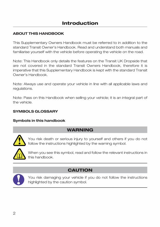
SYMBOLS GLOSSARY
Symbols in this handbook
You risk death or serious injury to yourself and others if you do notfollow the instructions highlighted by the warning symbol.
When you see this symbol, read and follow the relevant instructions inthis handbook.
You risk damaging your vehicle if you do not follow the instructionshighlighted by the caution symbol.
WARNING
CAUTION
Introduction
SAFETY FIRST
The basis for Health and Safety law in the UK is the Health and Safety at WorkAct 1974 and its amendments. Guidance to its application to road vehicle useis available from the Health and Safety Executive (HSE) and many otherprofessional bodies is recommended. Certificate of Professional Competence(CPC) training (2003/59/EC) is also recommended and in some casesmandatory for Commercial Vehicle drivers.
It is the responsibility of the Driver, Owner and/or Operator to establish whatHealth and Safety legislation applies when using this vehicle and that onlycompetent persons be allowed to use the vehicle.
The vehicle has been designed for the carriage of goods, if the vehicle ismodified or used for other purposes i.e. a work platform, additional safetyequipment maybe required. A full risk assessment should be conducted toascertain requirements.
WARRANTY
Full 3 Year / 100,000 Mile warranty on all parts and workmanship associated withthe Dropside body conversion applies, including a 3 year perforation warranty. Warranty is only valid if the Dropside has been operated in accordance with theSupplementary Owners Handbook.
Warranty claims for parts associated with the Dropside body conversionshould be made direct to VFS (Southampton) Ltd.
VFS (Southampton) Ltd. Unit 8 Barton Park Industrial EstateChickenhall Lane, Eastleigh, Hampshire, SO50 6RR
PARTS AND ACCESSORIES
Spare parts and accessories are available from VFS (Southampton) Ltd.Tel 02380 651 704 . Fax 02380 620 999 . Email: [email protected] information can be found under the Spare Parts section of the VFSWebsite. www.vfs.co.ukAll Maintenance and service repairs should be logged in the section providedin this handbook.
3
4
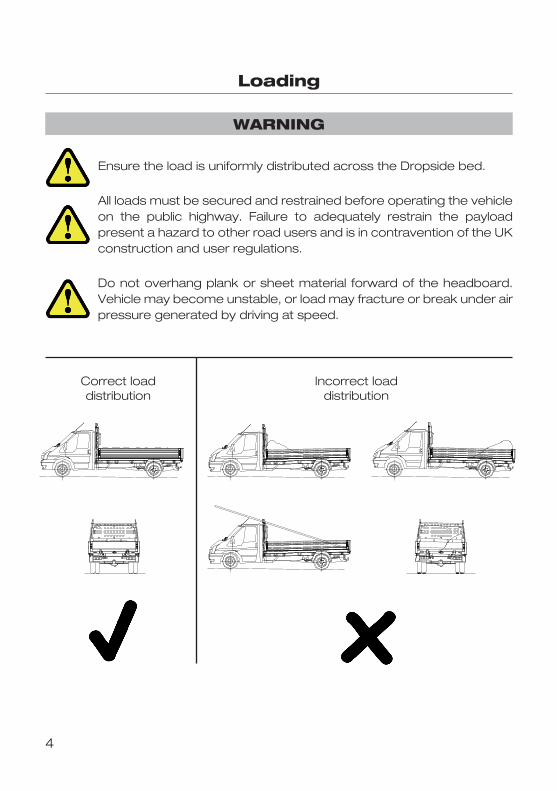
Loading
Ensure the load is uniformly distributed across the Dropside bed.
All loads must be secured and restrained before operating the vehicleon the public highway. Failure to adequately restrain the payloadpresent a hazard to other road users and is in contravention of the UKconstruction and user regulations.
Do not overhang plank or sheet material forward of the headboard.Vehicle may become unstable, or load may fracture or break under airpressure generated by driving at speed.
Correct loaddistribution
Incorrect loaddistribution
WARNING
5
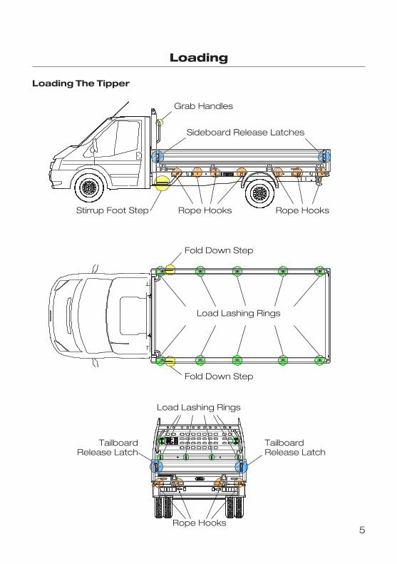
Loading
Loading The Tipper
Grab Handles
Sideboard Release Latches
Stirrup Foot Step Rope Hooks Rope Hooks
Fold Down Step
Fold Down Step
Load Lashing Rings
Load Lashing Rings
TailboardRelease Latch
TailboardRelease Latch
Rope Hooks
6
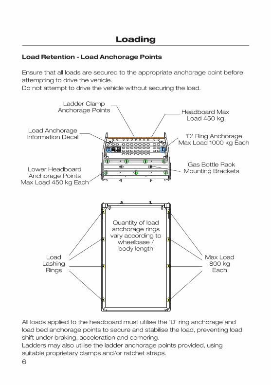
Loading
Load Retention � Load Anchorage Points
Ensure that all loads are secured to the appropriate anchorage point beforeattempting to drive the vehicle.Do not attempt to drive the vehicle without securing the load.
All loads applied to the headboard must utilise the 'D' ring anchorage andload bed anchorage points to secure and stabilise the load, preventing loadshift under braking, acceleration and cornering.Ladders may also utilise the ladder anchorage points provided, usingsuitable proprietary clamps and/or ratchet straps.
LoadLashingRings
Max Load800 kgEach
Quantity of load anchorage rings vary according to wheelbase / body
length.
'D' Ring Anchorage Max Load 1000 kg Each
Lower HeadboardAnchorage Points
Max Load 450 kg Each
Gas Bottle RackMounting Brackets
Headboard Max Load 450 kg
Load AnchorageInformation Decal
Ladder Clamp Anchorage PointsLadder Clamp
Anchorage Points Headboard MaxLoad 450 kg
'D' Ring AnchorageMax Load 1000 kg Each
Gas Bottle RackMounting Brackets
Load AnchorageInformation Decal
Lower HeadboardAnchorage Points
Max Load 450 kg Each
LoadLashingRings
Max Load800 kgEach
Quantity of loadanchorage rings
vary according towheelbase /body length
7
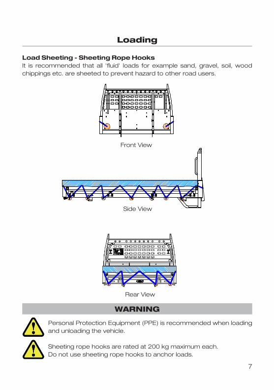
Loading
Load Sheeting � Sheeting Rope HooksIt is recommended that all 'fluid' loads for example sand, gravel, soil, woodchippings etc. are sheeted to prevent hazard to other road users.
Personal Protection Equipment (PPE) is recommended when loadingand unloading the vehicle.
Sheeting rope hooks are rated at 200 kg maximum each.Do not use sheeting rope hooks to anchor loads.
Side View
Front ViewFront View
Side View
Rear View
WARNING
8
Load Bed Access
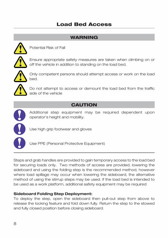
Steps and grab handles are provided to gain temporary access to the load bedfor securing loads only. Two methods of access are provided, lowering thesideboard and using the folding step is the recommended method, howeverwhere load spillage may occur when lowering the sideboard, the alternativemethod of using the stirrup steps may be used. If the load bed is intended tobe used as a work platform, additional safety equipment may be required
Sideboard Folding Step Deployment:To deploy the step, open the sideboard then pull�out step from above torelease the locking feature and fold down fully. Return the step to the stowedand fully closed position before closing sideboard.
Potential Risk of Fall
Ensure appropriate safety measures are taken when climbing on oroff the vehicle in addition to standing on the load bed.
Only competent persons should attempt access or work on the loadbed.
Do not attempt to access or demount the load bed from the trafficside of the vehicle
Additional step equipment may be required dependent uponoperator’s height and mobility.
Use high grip footwear and gloves
Use PPE (Personal Protective Equipment)
WARNING
CAUTION
9
Load Bed Access
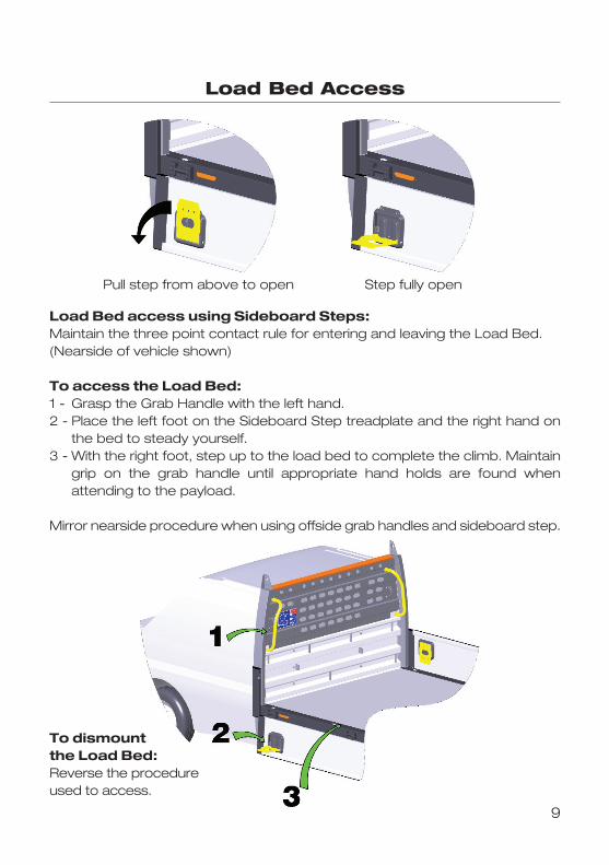
Load Bed access using Sideboard Steps:Maintain the three point contact rule for entering and leaving the Load Bed. (Nearside of vehicle shown)
To access the Load Bed:1 � Grasp the Grab Handle with the left hand.2 � Place the left foot on the Sideboard Step treadplate and the right hand on
the bed to steady yourself.3 � With the right foot, step up to the load bed to complete the climb. Maintain
grip on the grab handle until appropriate hand holds are found whenattending to the payload.
Mirror nearside procedure when using offside grab handles and sideboard step.
To dismount the Load Bed:Reverse the procedureused to access.
Pull step from above to open Step fully open
10
Load Bed Access
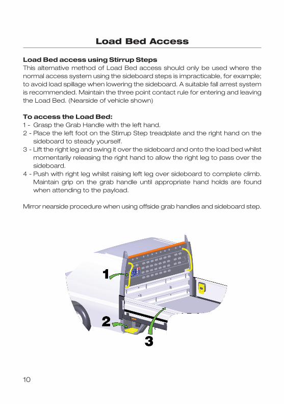
Load Bed access using Stirrup StepsThis alternative method of Load Bed access should only be used where thenormal access system using the sideboard steps is impracticable, for example;to avoid load spillage when lowering the sideboard. A suitable fall arrest systemis recommended. Maintain the three point contact rule for entering and leavingthe Load Bed. (Nearside of vehicle shown)
To access the Load Bed:1 � Grasp the Grab Handle with the left hand.2 � Place the left foot on the Stirrup Step treadplate and the right hand on the
sideboard to steady yourself.3 � Lift the right leg and swing it over the sideboard and onto the load bed whilst
momentarily releasing the right hand to allow the right leg to pass over thesideboard.
4 � Push with right leg whilst raising left leg over sideboard to complete climb.Maintain grip on the grab handle until appropriate hand holds are foundwhen attending to the payload.
Mirror nearside procedure when using offside grab handles and sideboard step.

11
Load Bed Access
To leave or dismount the Load Bed:1 � Grasp the grab handle with left hand, stand with your back to the sideboard.2 � With body lowered place the right hand on the sideboard to steady.3 � Lift the left leg and swing it over the sideboard and onto the treadplate.4 � Momentarily release the right hand and swing the right leg over the
sideboard, immediately placing the right hand back on the sideboard,lowering the right foot onto the ground. Finalise dismount by placing the leftfoot onto the ground then release hold on the Grab handle and Sideboard.
Mirror nearside procedure when using offside grab handles and sideboard step.
When using the Stirrup Step, it is recommended that a suitable Fallarrest system is used.
CAUTION
Controls
12
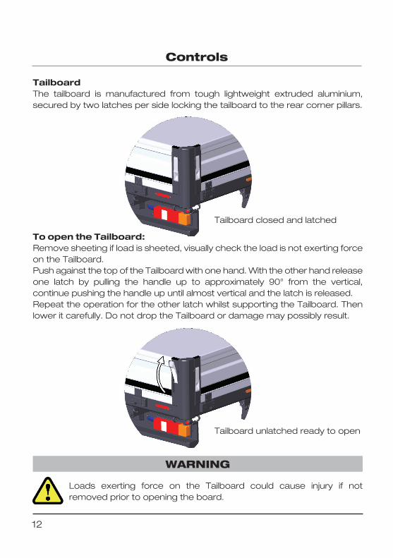
TailboardThe tailboard is manufactured from tough lightweight extruded aluminium,secured by two latches per side locking the tailboard to the rear corner pillars.
Loads exerting force on the Tailboard could cause injury if notremoved prior to opening the board.
WARNING
To open the Tailboard:Remove sheeting if load is sheeted, visually check the load is not exerting forceon the Tailboard.Push against the top of the Tailboard with one hand. With the other hand releaseone latch by pulling the handle up to approximately 90° from the vertical,continue pushing the handle up until almost vertical and the latch is released.Repeat the operation for the other latch whilst supporting the Tailboard. Thenlower it carefully. Do not drop the Tailboard or damage may possibly result.
Tailboard closed and latched
Tailboard unlatched ready to open

Controls
13
Tailboard cont'd.Once open the Tailboard is restrained in the horizontal position by Wire Straps.This allows loading or unloading the vehicle in conditions of reduced visibilitywithout obscuring the vehicle road lamps and number plate.Maximum load on the Tailboard not to exceed 150 kg
To open the Tailboard fully, support the board centrally and release the springclip from the eyelet at each end of the board. Then lower the board to thebumpstops.
Do not drive the vehicle with the Tailboard fully lowered as it obscuresthe vehicle rear lamps.
WARNING
Tailboard retained at 90°
Release both spring clipsto allow board to be fullylowered
14
Controls
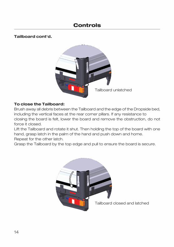
Tailboard cont'd.
To close the Tailboard:Brush away all debris between the Tailboard and the edge of the Dropside bed,including the vertical faces at the rear corner pillars. If any resistance toclosing the board is felt, lower the board and remove the obstruction, do notforce it closed.Lift the Tailboard and rotate it shut. Then holding the top of the board with onehand, grasp latch in the palm of the hand and push down and home.Repeat for the other latch.Grasp the Tailboard by the top edge and pull to ensure the board is secure.
Tailboard unlatched
Tailboard closed and latched
15
Controls
Tailboard cont'd.
Ensure the Tailboard is closed and locked before driving the vehicle.Never drive the vehicle with the Tailboard in the lowered position.
Vehicle lighting must remain on during loading/unloading through thehours of darkness or poor visibility.Avoid lowering the Tailboard when stationary on the public highway.
The Tailboard in the lowered position obscures the vehicle rear lights.Minimise the amount of time the board is lowered by closingimmediately after loading and unloading is completed. If unavoidable,a warning triangle or similar devices must be deployed warningapproaching drivers of a stationary vehicle with rear lamps obscured �Refer to page 21.
WARNING
16
Controls
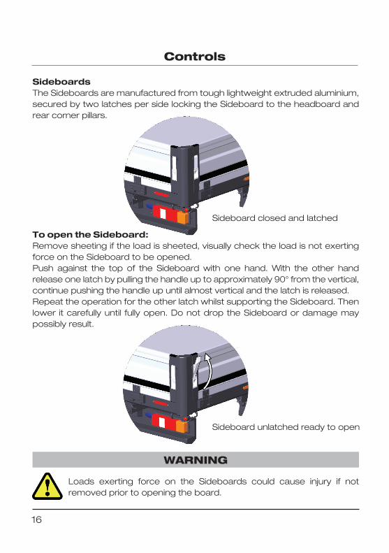
SideboardsThe Sideboards are manufactured from tough lightweight extruded aluminium,secured by two latches per side locking the Sideboard to the headboard andrear corner pillars.
Loads exerting force on the Sideboards could cause injury if notremoved prior to opening the board.
WARNING
To open the Sideboard:Remove sheeting if the load is sheeted, visually check the load is not exertingforce on the Sideboard to be opened.Push against the top of the Sideboard with one hand. With the other handrelease one latch by pulling the handle up to approximately 90° from the vertical,continue pushing the handle up until almost vertical and the latch is released.Repeat the operation for the other latch whilst supporting the Sideboard. Thenlower it carefully until fully open. Do not drop the Sideboard or damage maypossibly result.
Sideboard closed and latched
Sideboard unlatched ready to open
17
Controls
Sideboards cont’d.
Ensure both handles are latched and the Sideboard is secure beforedriving the vehicle.Never drive the vehicle with the Sideboards in the lowered position
WARNING
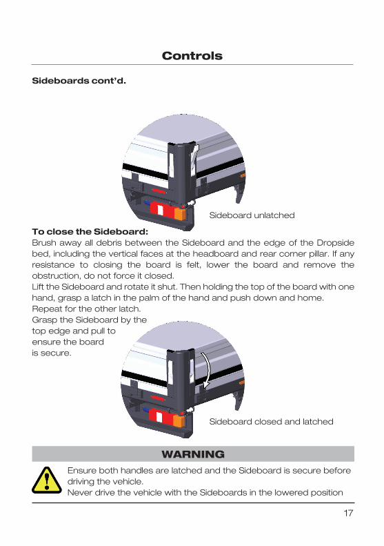
To close the Sideboard:Brush away all debris between the Sideboard and the edge of the Dropsidebed, including the vertical faces at the headboard and rear corner pillar. If anyresistance to closing the board is felt, lower the board and remove theobstruction, do not force it closed.Lift the Sideboard and rotate it shut. Then holding the top of the board with onehand, grasp a latch in the palm of the hand and push down and home.Repeat for the other latch.Grasp the Sideboard by the top edge and pull to ensure the boardis secure.
Sideboard unlatched
Sideboard closed and latched

18
Maintenance
Drivers Checks and Maintenance Items
The driver, regardless of ownership of the vehicle must perform the followingchecks and vehicle maintenance. If the driver does not own the vehicle, theowner of the vehicle must satisfy himself or herself that the driver to whom thevehicle has been allocated will carry out these essential checks. The drivermust be made aware of the responsibilities to read and understand theSupplementary Dropside Handbook and carry out the essential MaintenanceChecks in line with the maintenance procedure in this section.
Daily Driver Checks
• Check the Supplementary Dropside Handbook is complete and locatedin a safe position within the cab.
• Check the Load Deck for damage, clean and remove any material thathas stuck to it, ensure the surface is smooth and free from debris thatmay snag loads.
• Check the security of all Side and Tailboard Latches.• Check the Rear Lights and Licence Plate to ensure any site debris or
mud thrown up from the rear wheels has not obscured them.• Ensure the Warning Triangle is present and located securely in the cab.• Ensure all items in the load Bed are secured to ensure no item presents
a danger to traffic or pedestrians. Sheeting the Load Deck may berequired dependent upon the load.
• Ensure the Load Lashing Equipment (Straps, Rope and Sheet etc.) isavailable for load types to be carried.
Only competent technical trained personnel should carry outmaintenance involving adjustment or replacement of bodyworkcomponents on this Dropside.
It is imperative that the recommended Driver Checks andMaintenance be carried out to ensure the safe and efficient operationof the Dropside.
WARNING
CAUTION
19
Maintenance
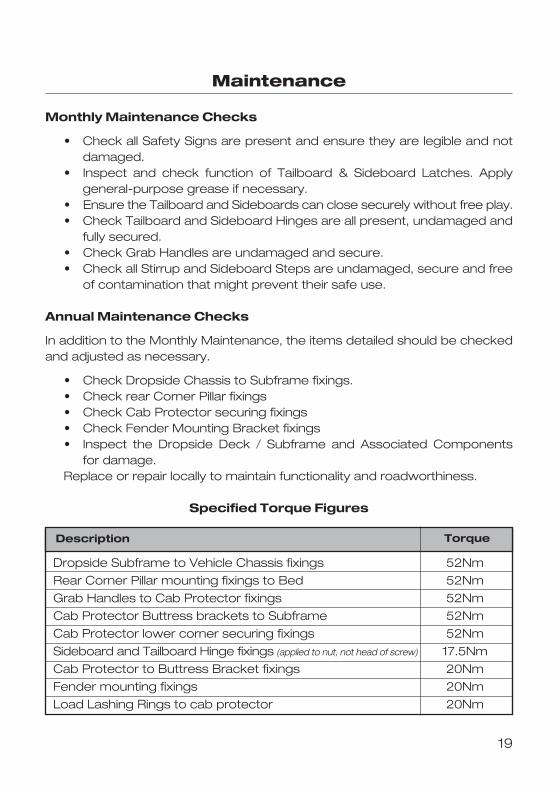
Monthly Maintenance Checks
• Check all Safety Signs are present and ensure they are legible and notdamaged.
• Inspect and check function of Tailboard & Sideboard Latches. Applygeneral�purpose grease if necessary.
• Ensure the Tailboard and Sideboards can close securely without free play.• Check Tailboard and Sideboard Hinges are all present, undamaged and
fully secured.• Check Grab Handles are undamaged and secure.• Check all Stirrup and Sideboard Steps are undamaged, secure and free
of contamination that might prevent their safe use.
Annual Maintenance Checks
In addition to the Monthly Maintenance, the items detailed should be checkedand adjusted as necessary.
• Check Dropside Chassis to Subframe fixings.• Check rear Corner Pillar fixings• Check Cab Protector securing fixings• Check Fender Mounting Bracket fixings• Inspect the Dropside Deck / Subframe and Associated Components
for damage.Replace or repair locally to maintain functionality and roadworthiness.
Specified Torque Figures
Description Torque
Dropside Subframe to Vehicle Chassis fixings 52Nm
Rear Corner Pillar mounting fixings to Bed 52Nm
Grab Handles to Cab Protector fixings 52Nm
Cab Protector Buttress brackets to Subframe 52Nm
Cab Protector lower corner securing fixings 52Nm
Sideboard and Tailboard Hinge fixings (applied to nut, not head of screw) 17.5Nm
Cab Protector to Buttress Bracket fixings 20Nm
Fender mounting fixings 20Nm
Load Lashing Rings to cab protector 20Nm
20
Safety Signs
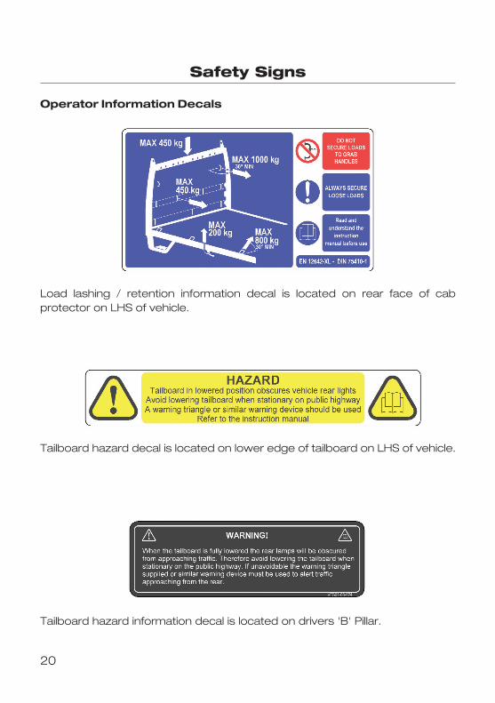
Operator Information Decals
Load lashing / retention information decal is located on rear face of cabprotector on LHS of vehicle.
Tailboard hazard decal is located on lower edge of tailboard on LHS of vehicle.
Tailboard hazard information decal is located on drivers 'B' Pillar.
21
Emergency Equipment
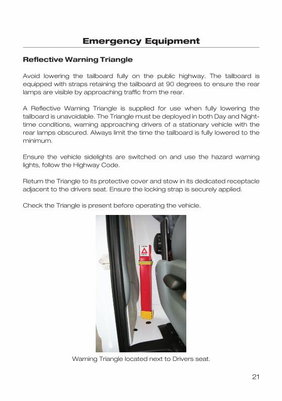
Reflective Warning Triangle
Avoid lowering the tailboard fully on the public highway. The tailboard isequipped with straps retaining the tailboard at 90 degrees to ensure the rearlamps are visible by approaching traffic from the rear.
A Reflective Warning Triangle is supplied for use when fully lowering thetailboard is unavoidable. The Triangle must be deployed in both Day and Night�time conditions, warning approaching drivers of a stationary vehicle with therear lamps obscured. Always limit the time the tailboard is fully lowered to theminimum.
Ensure the vehicle sidelights are switched on and use the hazard warninglights, follow the Highway Code.
Return the Triangle to its protective cover and stow in its dedicated receptacleadjacent to the drivers seat. Ensure the locking strap is securely applied.
Check the Triangle is present before operating the vehicle.
Warning Triangle located next to Drivers seat.
22
Towing
Do not exceed the maximum Gross Train Mass stated on the vehicleidentification plate. Do not exceed the maximum gross Trailer mass as stated on the Registration document. Refer to the 'Vehicleidentification'' and 'Towing a Trailer' section in the Ford TransitOwner’s Handbook
If an aftermarket Tow Bar is being installed ensure that the tailboard isfitted with a protective guide. This will prevent potential damage fromthe tow bar/ball/clevis when the tailboard is lowered.
WARNING
CAUTION
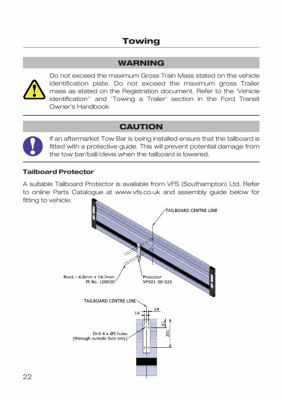
Tailboard Protector
A suitable Tailboard Protector is available from VFS (Southampton) Ltd. Referto online Parts Catalogue at www.vfs.co.uk and assembly guide below forfitting to vehicle.
23
Lighting
Before changing Lamps, switch off the ignition.
Only fit Lamps of the correct specification.
WARNING
CAUTION
Marker Lamps:
End Outline Marker Lamps:
• The End Outline Marker Lamps are LED type and non�serviceable.Replacement lamps can be obtained from VFS (Southampton) Ltd
Side Marker Lamps (Double Cab and Extended Frame only):
• The Side Marker Lamps are LED type and non�serviceable.Replacement lamps can be obtained from VFS (Southampton) Ltd
Remove apparently harmless looking substances from the paintworkimmediately (e.g bird droppings, tree resins, insect remains, tar spots,road salt and industrial fall�out)
24
Vehicle Care
If the vehicle has been to transport corrosive material e.g. road salt,the load bed should be washed as soon as possible, therebypreventing any potential corrosion. After washing, any residual saltshould be neutralised with a salt neutralising solution, thoroughlyrinsing afterwards to ensure both residual salt and neutraliser arecompletely removed from all surfaces.
The use of a high pressure washer could cause damage to certainparts of your vehicle.
WARNING
CAUTION
CAUTION
Cleaning the bodywork
Regular cleaning of the Dropside bodywork will maintain its function and value.It is important to ensure that debris does not build up on the load bed impedingthe closure of the side and tailboards. Brush the load bed with a soft broom toclear the floor of debris and brush off the body edges and generally cleanaround the bodyside and/or tailboard apertures to ensure the side andtailboard can be closed without jamming.
Use only soapy water (car shampoo) when washing; avoid high powerdetergents as this may have a detrimental effect on the paint finish andPhenolic Ply floor. Always rinse down with fresh water afterwards.If the vehicle has been used on muddy/dirty sites, always wash down thewheels, rear taillights, licence plate and lamps before joining the public highway.
Repairing Minor Paint damage
You should repair paintwork damaged by stones from the road or minorscratches as soon as possible. Any paint damage to bodywork parts finishedin Slate Grey should be immediately touched�up with a Zinc rich or coldgalvanising paint. Paint damage to the Side and Tailboards can be touched�upor repaired using normal automotive touch�up pencils and methods.
25
Vehicle Identification
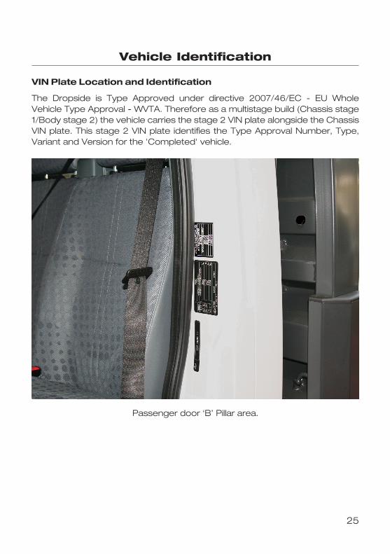
VIN Plate Location and Identification
The Dropside is Type Approved under directive 2007/46/EC � EU WholeVehicle Type Approval � WVTA. Therefore as a multistage build (Chassis stage1/Body stage 2) the vehicle carries the stage 2 VIN plate alongside the ChassisVIN plate. This stage 2 VIN plate identifies the Type Approval Number, Type,Variant and Version for the 'Completed' vehicle.
Passenger door ‘B’ Pillar area.

26
Vehicle Identification
Body Type and Serial Number
The Dropside bodywork has its own ID plate for use when ordering spare partsor warrenty enquiries.
Important information such as the Body Serial Number and Type can be foundas well as contact details
BUILD DATE
BODY TYPE
BODY SERIAL No.
WARRANTYPARTS & SERVICE
QUOTE BODY TYPE AND SERIALNUMBER WHEN ENQUIRING
TEL 02380 651704FAX 02380 620999
VEHICLE MUST ALWAYS BE OPERATEDWITHIN ITS PLATED WEIGHTS
VFS (SOUTHAMPTON) LTDUNIT 8 BARTON PARKINDUSTRIAL ESTATE,
EASTLEIGH,HAMPSHIRE,
SO50 6RR

27
Vehicle Dimensions
SWB Single Cab Narrow Body (Single Rear Wheel) CF003
Height dimensions are approximate and dependant upon suspension,wheel and tyre equipment fitted.Always physically check vehicle height when height restrictions areencountered. Heights do not include any loads.
CAUTION
28
Vehicle Dimensions
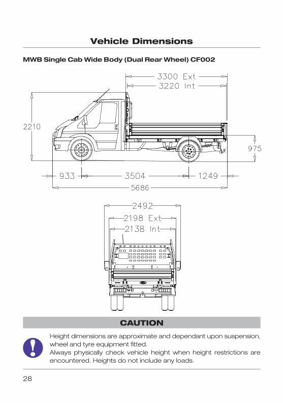
MWB Single Cab Wide Body (Dual Rear Wheel) CF002
Height dimensions are approximate and dependant upon suspension,wheel and tyre equipment fitted.Always physically check vehicle height when height restrictions areencountered. Heights do not include any loads.
CAUTION

29
Vehicle Dimensions
LWB Single Cab Wide Body (Dual Rear Wheel) CF001
Height dimensions are approximate and dependant upon suspension,wheel and tyre equipment fitted.Always physically check vehicle height when height restrictions areencountered. Heights do not include any loads.
CAUTION

30
Vehicle Dimensions
LWB�EF Single Cab Wide Body (Dual Rear Wheel) CF000
Height dimensions are approximate and dependant upon suspension,wheel and tyre equipment fitted.Always physically check vehicle height when height restrictions areencountered. Heights do not include any loads.
CAUTION
31
Vehicle Dimensions
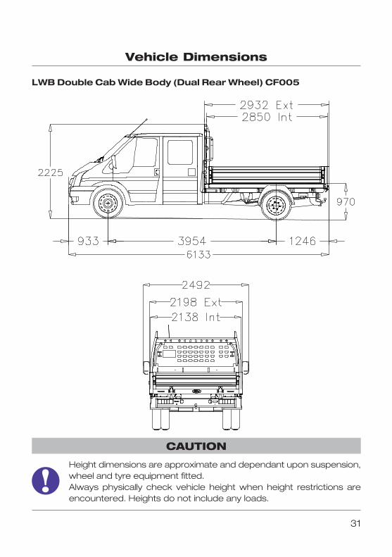
LWB Double Cab Wide Body (Dual Rear Wheel) CF005
Height dimensions are approximate and dependant upon suspension,wheel and tyre equipment fitted.Always physically check vehicle height when height restrictions areencountered. Heights do not include any loads.
CAUTION
32
Vehicle Dimensions
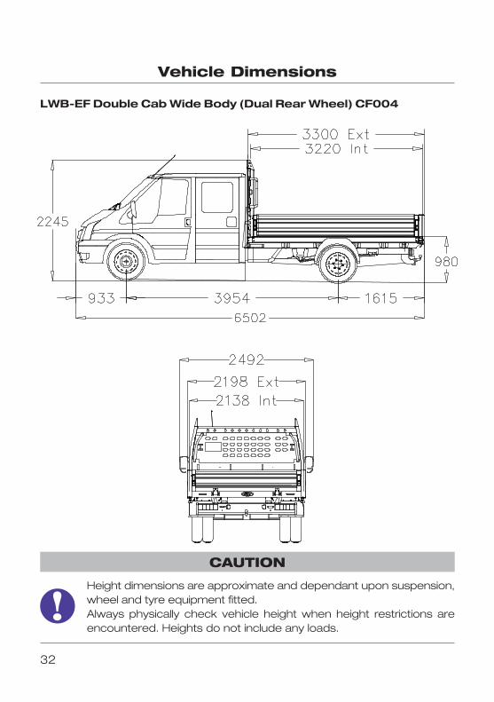
LWB�EF Double Cab Wide Body (Dual Rear Wheel) CF004
Height dimensions are approximate and dependant upon suspension,wheel and tyre equipment fitted.Always physically check vehicle height when height restrictions areencountered. Heights do not include any loads.
CAUTION
33
Vehicle Dimensions
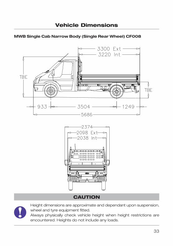
MWB Single Cab Narrow Body (Single Rear Wheel) CF008
Height dimensions are approximate and dependant upon suspension,wheel and tyre equipment fitted.Always physically check vehicle height when height restrictions areencountered. Heights do not include any loads.
CAUTION
34
Vehicle Dimensions
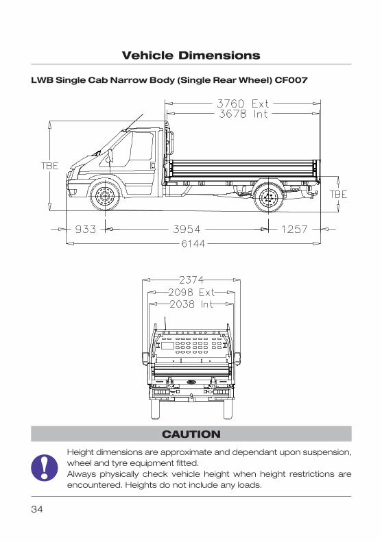
LWB Single Cab Narrow Body (Single Rear Wheel) CF007
Height dimensions are approximate and dependant upon suspension,wheel and tyre equipment fitted.Always physically check vehicle height when height restrictions areencountered. Heights do not include any loads.
CAUTION
35
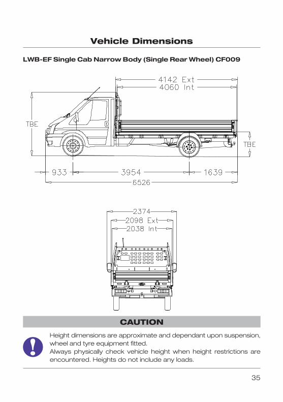
Vehicle Dimensions
LWB�EF Single Cab Narrow Body (Single Rear Wheel) CF009
Height dimensions are approximate and dependant upon suspension,wheel and tyre equipment fitted.Always physically check vehicle height when height restrictions areencountered. Heights do not include any loads.
CAUTION

36
Maintenance & Repair Log
Date
Mileage
Service Agent/Repairer:
Maintenance/Repair action
Date
Mileage
Service Agent/Repairer:
Maintenance/Repair action
37
Maintenance & Repair Log
Date
Mileage
Service Agent/Repairer:
Maintenance/Repair action
Date
Mileage
Service Agent/Repairer:
Maintenance/Repair action
38
Maintenance & Repair Log
Date
Mileage
Service Agent/Repairer:
Maintenance/Repair action
Date
Mileage
Service Agent/Repairer:
Maintenance/Repair action

39
Maintenance & Repair Log
Date
Mileage
Service Agent/Repairer:
Maintenance/Repair action
Date
Mileage
Service Agent/Repairer:
Maintenance/Repair action
40
Index
A About this Handbook 2Accessories 3Annual Maintenance Checks 19
BBody Identification Plate 26
C Changing a Marker Lamp 23Cleaning the Bodywork 24Controls 5Correct Load Distribution 4
DDaily Driver Checks 18
EEmergency Equipment 21End Outline Marker Lamps 23
FFluid Loads 7
IIncorrect Load Distribution 4Introduction 2
LLadder Clamps 6Layout 5LED Marker Lamps 23Lighting 23Loading 4 Load Bed Access 8Load Carrying 4Load Retention
� Load Anchorage Points 5Load Sheeting – Rope Hooks 7
MMaintenance 18Marker Lamp 23Monthly Maintenance Checks 19
NNon Fluid Loads 7Notes 41
OOperator Information Decals 20
PParts and Accessories 3Personal Protection Equipment 7, 8
RRepairing Minor Paint Damage 24Reflective Warning Triangle 21Rope Hooks 5, 7
SSafety First 3Safety Signs 20Sideboards 5, 16Sideboard Operation 16Side Marker Lamps 23Spare Parts and Accessories 3, 26Specified Torque Figures 19Symbols Glossary 2
TTailboard 5, 12Tailboard Protection 22Torque Figures 19Towing 22
VVehicle Care 24Vehicle Dimensions 27�35Vehicle Identification 25�26Vehicle Layout 5�7VIN Plate 25
WWarning Triangle 21Warranty 3
Description Page Description Page

41
Notes
