transmission lines and waveguides
DESCRIPTION
Notes for transmission lines and waveguidesTRANSCRIPT

DEPARTMENT OF ELECTRONICS AND COMMUNICATION
ENGINEERING
SUBJECT CODE: EC1305
TRANSMISSION LINES AND WAVEGUIDES
(FOR FIFTH SEMESTER ECE)
TWO MARK QUESTIONS-ANSWERS
PREPARED BY
S.BEEMA BEEVI (L/ECE)

DEPARTMENT OF ELECTRONICS AND COMMUNICATION ENGINEERING
SUBJECT CODE: EC 1305 SUBJECT: TRANSMISSION LINES AND WAVEGUIDES
(FOR FIFTH SEMESTER ECE)
TWO MARKS QUESTIONS
UNIT I-TRANSMISSION LINE THEORY
1.Define the line parameters?
The parameters of a transmission line are:
Resistance (R)
Inductance (L)
Capacitance (C)
Conductance (G)
Resistance (R) is defined as the loop resistance per unit length of the wire. Its
unit is ohm/Km
Inductance (L) is defined as the loop inductance per unit length of the wire. Its
unit is Henry/Km
Capacitance (C) is defined as the loop capacitance per unit length of the wire. Its
unit is Farad/Km
Conductance (G) is defined as the loop conductance per unit length of the wire.
Its unit is mho/Km
2. What are the secondary constants of a line? Why the line parameters are called
distributed elements?
The secondary constants of a line are:
Characteristic Impedance
Propagation Constant
Since the line constants R, L, C, G are distributed through the entire length of the
line, they are called as distributed elements. They are also called as primary constants.
3.Define Characteristic impedance
Characteristic impedance is the impedance measured at the sending end of the
line. It is given by Z0 = Z/Y,where
Z = R + jωL is the series impedance
Y = G + jωC is the shunt admittance

4. Define Propagation constant
Propagation constant is defined as the natural logarithm of the ratio of the
sending end current or voltage to the receiving end current or voltage of the line. It gives
the manner in the wave is propagated along a line and specifies the variation of voltage
and current in the line as a function of distance. Propagation constant is a complex
quantity and is expressed as
γ = α + j β
The real part is called the attenuation constant α whereas the imaginary part of
propagation constant is called the phase constant β
5.What is a finite line? Write down the significance of this line?
A finite line is a line having a finite length on the line. It is a line, which is
terminated, in its characteristic impedance (ZR=Z0), so the input impedance of the finite
line is equal to the characteristic impedance (Zs=Z0).
6.What is an infinite line?
An infinite line is a line in which the length of the transmission line is infinite.
A finite line, which is terminated in its characteristic impedance, is termed as infinite
line. So for an infinite line, the input impedance is equivalent to the characteristic
impedance.
7.What is wavelength of a line?
The distance the wave travels along the line while the phase angle is changing
through 2Π radians is called a wavelength.
8.What are the types of line distortions?
The distortions occurring in the transmission line are called waveform
distortion or line distortion. Waveform distortion is of two types:
a) Frequency distortion
b) Phase or Delay Distortion.
9.How frequency distortion occurs in a line?
When a signal having many frequency components are transmitted along the
line, all the frequencies will not have equal attenuation and hence the received end
waveform will not be identical with the input waveform at the sending end because each
frequency is having different attenuation. This type of distortion is called frequency
distortion.
10.How to avoid the frequency distortion that occurs in the line?
In order to reduce frequency distortion occurring in the line,
a) The attenuation constant α should be made independent of frequency.
b) By using equalizers at the line terminals which minimize the frequency
distortion. Equalisers are networks whose frequency and phase
characteristics are adjusted to be inverse to those of the lines, which result

in a uniform frequency response over the desired frequency band, and
hence the attenuation is equal for all the frequencies.
11.What is delay distortion?
When a signal having many frequency components are transmitted along the
line, all the frequencies will not have same time of transmission, some frequencies being
delayed more than others. So the received end waveform will not be identical with the
input waveform at the sending end because some frequency components will be delayed
more than those of other frequencies. This type of distortion is called phase or delay
distortion.
12. How to avoid the frequency distortion that occurs in the line?
In order to reduce frequency distortion occurring in the line,
a) The phase constant β should be made dependent of frequency.
b) The velocity of propagation is independent of frequency.
c) By using equalizers at the line terminals which minimize the frequency
distortion. Equalizers are networks whose frequency and phase
characteristics are adjusted to be inverse to those of the lines, which
result in a uniform frequency response over the desired frequency
band, and hence the phase is equal for all the frequencies.
13.What is a distortion less line? What is the condition for a distortion less line?
A line, which has neither frequency distortion nor phase distortion is called a
distortion less line. The condition for a distortion less line is RC=LG. Also,
a) The attenuation constant α should be made independent of frequency.
b) The phase constant β should be made dependent of frequency.
d) The velocity of propagation is independent of frequency.
14.What is the drawback of using ordinary telephone cables?
In ordinary telephone cables, the wires are insulated with paper and twisted in
pairs, therefore there will not be flux linkage between the wires, which results in
negligible inductance, and conductance. If this is the case, the there occurs frequency and
phase distortion in the line.
15.How the telephone line can be made a distortion less line?
For the telephone cable to be distortion less line, the inductance value should
be increased by placing lumped inductors along the line.
16.What is Loading?
Loading is the process of increasing the inductance value by placing lumped
inductors at specific intervals along the line, which avoids the distortion

17.What are the types of loading?
a) Continuous loading
b) Patch loading
c) Lumped loading
18.What is continuous loading?
Continuous loading is the process of increasing the inductance value by
placing a iron core or a magnetic tape over the conductor of the line.
19.What is patch loading?
It is the process of using sections of continuously loaded cables separated by
sections of unloaded cables which increases the inductance value
20.What is lumped loading?
Lumped loading is the process of increasing the inductance value by placing
lumped inductors at specific intervals along the line, which avoids the distortion
21.Define reflection coefficient
Reflection Coefficient can be defined as the ratio of the reflected voltage to the
incident voltage at the receiving end of the line
Reflection Coefficient K=Reflected Voltage at load /Incident voltage at the load
K=Vr/Vi
22. Define reflection loss
Reflection loss is defined as the number of nepers or decibels by which the
current in the load under image matched conditions would exceed the current actually
flowing in the load
23.What is Impedance matching?
If the load impedance is not equal to the source impedance, then all the power
that are transmitted from the source will not reach the load end and hence some power is
wasted. This is called impedance mismatch condition. So for proper maximum power
transfer, the impedances in the sending and receiving end are matched. This is called
impedance matching.
24. Define the term insertion loss
The insertion loss of a line or network is defined as the number of nepers or
decibels by which the current in the load is changed by the insertion .
Insertion loss=Current flowing in the load without insertion of the
network/Current flowing in the load with insertion of the network

25.When reflection occurs in a line?
Reflection occurs because of the following cases:
1) when the load end is open circuited
2) when the load end is short-circuited
3) when the line is not terminated in its characteristic impedance
When the line is either open or short circuited, then there is not resistance at the
receiving end to absorb all the power transmitted from the source end. Hence all the
power incident on the load gets completely reflected back to the source causing
reflections in the line. When the line is terminated in its characteristic impedance, the
load will absorb some power and some will be reflected back thus producing reflections.
26.What are the conditions for a perfect line? What is a smooth line?
For a perfect line, the resistance and the leakage conductance value were
neglected. The conditions for a perfect line are R=G=0.
A smooth line is one in which the load is terminated by its characteristic
impedance and no reflections occur in such a line. It is also called as flat line.
UNIT II-RADIO FREQUENCY LINE
27. State the assumptions for the analysis of the performance of the radio frequency
line.
1.Due to the skin effect ,the currents are assumed to flow on the surface of the
conductor. The internal inductance is zero.
2.The resistance R increases with √ f while inductance L increases with f .
Hence ωL>>R.
3.The leakage conductance G is zero
28.State the expressions for inductance L of a open wire line and coaxial line.
For open wire line ,
L=9.21*10-7
(µ/µr +4ln d/a)=10-7
(µr+9.21log d/a) H/m
For coaxial line,
L = 4.60*10-7
[log b/a]H/m
29.State the expressions for the capacitance of a open wire line
For open wire line ,
C=(12.07)/(ln d/a)µµf/m
30.What is dissipationless line?
A line for which the effect of resistance R is completely neglected is called
dissipationless line .

31.What is the nature and value of Z0 for the dissipation less line?
For the dissipation less line, the Z0 is purley resistive and given by,
Z0=R0 = √ L/c
32.State the values of αααα and ββββ for the dissipation less line.
Answer:
α=0 and β=ω √LC
33.What are nodes and antinodes on a line?
The points along the line where magnitude of voltage or current is zero are
called nodes while the the points along the lines where magnitude of voltage or current
first maximum are called antinodes or loops.
34.What is standing wave ratio?
The ratio of the maximum to minimum magnitudes of voltage or current on a
line having standing waves called standing waves ratio.
Emax Imin
S = =
Emin Imin
35.What is the range of values of standing wave ratio?
The range of values of standing wave ratio is theoretically 1 to infinity.
36.State the relation between standing wave ratio and reflection coefficient.
Ans: S = 1+K
1-K
37.What are standing waves?
If the transmission is not terminated in its characteristic impedance ,then there
will be two waves traveling along the line which gives rise to standing waves having
fixed maxima and fixed minima.
38.What is called standing wave ratio?
The ratio of the maximum to minimum magnitudes of current or voltage on a line
having standing wave is called the standing-wave ratio S. That is,
S= E max = I max

Emin I min
39.State the relation between standing were ratio S and reflection co-efficient k.
The relation between standing wave ratio S and reflection co-efficient k is,
1+ k
S =
1- k
S-1
Also k =
S+1
40. How will you make standing wave measurements on coaxial lines?
For coaxial lines it is necessary to use a length of line in which a longitudinal
slot, one half wavelength or more long has been cut. A wire probe is inserted into
the air dielectric of the line as a pickup device, a vacuum tube voltmeter or other
detector being connected between probe and sheath as an indicator. If the meter
provides linear indications, S is readily determined. If the indicator is non linear,
corrections must be applied to the readings obtained.
41.Give the input impedance of a dissipationless line.
The input impedance of a dissipationless line is given by,
Z s = Es = R0 1+ k < φφφφ -2ββββs
I s 1- k <φφφφ -2ββββs
42.Give the maximum and minimum input impedance of the dissipationless line.
Maximum input impedance,
R max = R0 1+ k
1- k
= SRo
Minimum input impedance,
R min = Ro 1+ k
1- k
= Ro
S
43.Give the input impedance of open and short circuited lines.
The input impedance of open aned short circuited lines are given by,

Zsc = jRo tan 2 πs
λ
44.Why the point of voltage minimum is measured rather than voltage
maximum?
The point of a voltage minimum is measured rather than a voltage
maximum because it is usually possible to determine the exact point of
minimum voltage with greater accuracy.
45. What is the use of eighth wave line?
An eighth wave line is used to transform any resistance to an impendence with a
magnitude equal to Roof the line or to obtain a magnitude match between a resistance of
any value and a source of Ro internal resistance.
46. Give the input impendence of eighth wave line terminated in a pure resistance
Rr.
The input impendence of eighth wave line terminated in a pure resistance Rr. Is
given by
Zs = (ZR+jRo/Ro+jZR)
From the above equation it is seen that
Zs = Ro.
47. Why is a quarter wave line called as impendence inverter?
A quater wave line may be considered as an impendence inverter because it can
transform a low impendence in to ahigh impendence and vice versa.
48. What is the application of the quarter wave matching section ?
An important application of the quarter wave matching sectionis to a couple a
transmission line to a resistive load such as an antenna .The quarter –wave matching
section then must be designed to have a characteristic impendence Ro so chosen that the
antenna resistance Ra is transformed to a value equal to the characteristic impendence Ra
of the transmission line.The characteristic impendence Ro of the matching section
then should be
Ro’ = √ Ra Ro
49. What do you mean by copper insulators?
An application of the short circuited quarter wave line is an insulator to support
an open wire line or the center conductor of a coaxial line .This application makes se of
the fact that the input impendence of a quarter –wave shorted line is very high ,Such lines
are sometimes referred to as copper insulators.
50. Bring out the significance of a half wavelength line.

A half wavelength line may be considered as a one- to – one
transformer. It has its greatest utility in connecting load to a source in cases where the
load source cannot be made adjacent.
51. Give some of the impendence –matching devices.
The quarter – wave line or transformer and the tapered line are some of the
impendence –matching devices.
52. Explain impendence matching using stub.
In the method of impendence matching using stub ,an open or closed stub line of
suitable length is used as a reactance shunted across the transmission line at a designated
distance from the load ,to tune the length of the line and the load to resonance with an
antiresonant resistance equal to Ro.
53.Give reasons for preferring a short- circuited stub when compared to an open –
circuited stub.
A short circuited stub is preferred to an open circuited stub because of
greater ease in constructions and because of the inability to maintain high enough
insulation resistance at the open –circuit point to ensure that the stub is really open-
circuited .A shorted stub also has a lower loss of energy due to radiation ,since the short –
circuit can be definitely established with a large metal plate ,effectively stopping all field
propagation.
54.What are the two independent measurements that must be made to find the
location and length of the stub.
The standing wave ratio S and the position of a voltage minimum are the
independent measurements that must be made to find the location and length of the stub.
55.Give the formula to calculate the distance of the point from the load at which the
stub is to be connected.
The formula to calculate the distance of the point from the load at which the
stub is to be connected is,
S1 = (φ +π-cos-1
|K|)/(2β)
56. Give the formula to calculate the distance d from the voltage minimum to the
point stub be connection.
The formula to calculate the distance d from the voltage minimum to the point of
stub be connection is,
d= cos-1
|K| / (2β)
57. Give the formula to calculate the length of the short circuited stub.

The formula to calculate the length of the short circuited stub is,
L=λ/2Π tan-1
(√s/(s-1))
This is the length of the short – circuited stub to be placed d meters
towards the load from a point at which a voltage minimum existed before
attachment of the stub.
58. What is the input impendence equation of a dissipation less line ?
The input impendence equation of a dissipation less line is given by
(Zs/Ro)=(1+|K|(Ф-2βs)/ (1-|K|(Ф-2βs)
59.Give the equation for the radius of a circle diagram.
The equation for the radius of a circle diagram is
R=(S2-1)/2S and
C = (S2+1)/2S
Where C is the shift of the center of the circle on the positive Ra axis.
60.What is the use of a circle diagram?
The circle diagram may be used to find the input impendence of a line mof any
chosen length.
61. How is the circle diagram useful to find the input impendence of short and open
circuited lines?
An open circuited line has s = α ,the correspondent circle appearing as the vertical
axis .The input impendence is then pure reactance , with the value for various electrical
lengths determined by the intersections of the corresponding βs circles with the vertical
axis.
A short circuited line may be solved by determining its amittance .The S circle is
again the vertical axis, and susceptance values may be read off at appropriate intersection
of the βs circles with the vertical axis.
62. List the applications of the smith chart.
The applications of the smith chart are,
(i) It is used to find the input impendence and input admittance of the line.
(ii) The smith chart may also be used for lossy lines and the locus of points on a
line then follows a spiral path towards the chart center, due to attenuation.

(iii) In single stub matching
63. What are the difficulties in single stub matching?
The difficulties of the smith chart are
(i) Single stub impedance matching requires the stub to be located
at a definite point on the line. This requirement frequently calls
for placement of the stub at an undesirable place from a
mechanical view point.
(ii) For a coaxial line, it is not possible to determine the location of
a voltage minimum without a slotted line section, so that
placement of a stub at the exact required point is difficult.
(iii) In the case of the single stub it was mentioned that two
adjustments were required ,these being location and length of
the stub.
64. What is double stub matching?
Another possible method of impedance matching is to use two stubs in which the
locations of the stub are arbitrary,the two stub lengths furnishing the required
adjustments.The spacing is frequently made λ/4.This is called double stub matching.
65. Give reason for an open line not frequently employed for impedance matching.
An open line is rarely used for impedance matching because of radiation losses
from the open end,and capacitance effects and the difficulty of a smooth adjustment of
length.
66. State the use of half wave line .
The expression for the input impendence of the line is given by
Zs = Zr
Thus the line repeats is terminating impedance .Hence it is operated as one to one
transformer .Its application is to connect load to a source where they can not be made
adjacent.
67. Why Double stub matching is preferred over single stub matching.
Double stub matching is preferred over single stub due to following
disadvantages of single stub.
1. Single stub matching is useful for a fixed frequency . So as frequency changes
the location of single stub will have to be changed.
2. The single stub matching system is based on the measurement of voltage
minimum .Hence for coxial line it is very difficult to get such voltage
minimum, without using slotted line section.
UNIT III-GUIDED WAVES

68. What are guided waves? Give examples
The electromagnetic waves that are guided along or over conducting or
dielectric surface are called guided waves.
Examples: Parallel wire, transmission lines
69. What is TE wave or H wave?
Transverse electric (TE) wave is a wave in which the electric field
strength E is entirely transverse. It has a magnetic field strength Hz in the direction of
propagation and no component of electric field Ez in the same direction
70. What is TH wave or E wave?
Transverse magnetic (TM) wave is a wave in which the magnetic field
strength H is entirely transverse. It has a electric field strength Ez in the direction of
propagation and no component of magnetic field Hz in the same direction
71. What is a TEM wave or principal wave?
TEM wave is a special type of TM wave in which an electric field E
along the direction of propagation is also zero. The TEM waves are waves in which both
electric and magnetic fields are transverse entirely but have no components of Ez and Hz
.it is also referred to as the principal wave.
72. What is a dominant mode?
The modes that have the lowest cut off frequency is called the dominant
mode.
73. Give the dominant mode for TE and TM waves
Dominant mode: TE10 and TM10
74. What is cut off frequency?
The frequency at which the wave motion ceases is called cut-off frequency
of the waveguide.
75. What is cut-off wavelength?
It is the wavelength below which there is wave propagation and above
which there is no wave propagation.
76. Write down the expression for cut off frequency when the wave is propagated in
between two parallel plates.
The cut-off frequency, fc = m/ (2a (µΕ)1/2
)
77. Mention the characteristics of TEM waves.
a) It is a special type of TM wave
b) It doesn’t have either e or H component
c) Its velocity is independent of frequency
d) Its cut-off frequency is zero.

78. Define attenuation factor
Attenuation factor = (Power lost/ unit length)/(2 x power transmitted)
79. Give the relation between the attenuation factor for TE waves and TM waves
αTE = αTM (fc/f)2
80. Define wave impedance
Wave impedance is defined as the ratio of electric to magnetic field strength
Zxy
= Ex/ Hy in the positive direction
Zxy
= -Ex/ Hy in the negative direction
81. What is a parallel plate wave guide?
Parallel plate wave guide consists of two conducting sheets separated by a
dielectric material.
82.Why are rectangular wave-guides preferred over circular wave-guides?
Rectangular wave-guides preferred over circular wave guides because of the
following reasons.
a) Rectangular wave guide is smaller in size than a circular wave guide of the
same operating frequency
b) It does not maintain its polarization through the circular wave guide
c) The frequency difference between the lowest frequency on dominant
mode and the next mode of a rectangular wave-guide is bigger than in a
circular wave guide.
83.Mention the applications of wave guides
The wave guides are employed for transmission of energy at very high
frequencies where the attenuation caused by wave guide is smaller.
Waveguides are used in microwave transmission.Circular waveguides are used
as attenuators and phase shifters
UNIT IV-RECTANGULAR WAVEGUIDES
84.Why is circular or rectangular form used as waveguide?
Waveguides usually take the form of rectangular or circular cylinders because of
its simpler forms in use and less expensive to manufacture.
85. What is an evanescent mode?
When the operating frequency is lower than the cut-off frequency, the propagation
constant becomes real i.e., γ = α . The wave cannot be propagated. This non- propagating
mode is known as evanescent mode.
87.What is the dominant mode for the TE waves in the rectangular waveguide?
The lowest mode for TE wave is TE10 (m=1 , n=0)

88. What is the dominant mode for the TM waves in the rectangular waveguide?
The lowest mode for TM wave is TM11(m=1 , n=1)
89. What is the dominant mode for the rectangular waveguide?
The lowest mode for TE wave is TE10 (m=1 , n=0) whereas the lowest mode for
TM wave is TM11(m=1 , n=1). The TE10 wave have the lowest cut off frequency
compared to the TM11 mode. Hence the TE10 (m=1 , n=0) is the dominant mode of a
rectangular waveguide.Because the TE10 mode has the lowest attenuation of all modes in
a rectangular waveguide and its electric field is definitely polarized in one direction
everywhere.
10.Which are the non-zero field components for the for the TE10 mode in a rectangular
waveguide?
Hx, Hz and Ey.
90. Which are the non-zero field components for the for the TM11 mode in a
rectangular waveguide?
Hx, Hy ,Ey. and Ez.
91. Define characteristic impedance in a waveguide
The characteristic impedance Zo can be defined in terms of the voltage-current
ratio or in terms of power transmitted for a given voltage or a given current.
Zo (V,I) = V/I
92.Why TEM mode is not possible in a rectangular waveguide?
Since TEM wave do not have axial component of either E or H ,it cannot
propagate within a single conductor waveguide
93.Explain why TM01 and TM10 modes in a rectangular waveguide do not exist.
For TM modes in rectangular waveguides, neither m or n can be zero because
all the field equations vanish ( i.e., Hx, Hy ,Ey. and Ez.=0). If m=0,n=1 or m=1,n=0 no
fields are present. Hence TM01 and TM10 modes in a rectangular waveguide do not exist.
94. What are degenerate modes in a rectangular waveguide?
Some of the higher order modes, having the same cut off frequency , are
called degenerate modes. In a rectangular waveguide , TEmn and TMmn modes ( both m ≠
0 and n ≠ 0) are always degenerate.
UNIT V-CIRCULAR WAVEGUIDES AND CAVITY RESONATORS
95.What is a circular waveguide?
A circular waveguide is a hollow metallic tube with circular cross-
section for propagating the electromagnetic waves by continuous reflections from
the surfaces or walls of the guide
96.Why circular waveguides are not preferred over rectangular waveguides?
The circular waveguides are avoided because of the following reasons:
a) The frequency difference between the lowest frequency on the dominant
mode and the next mode is smaller than in a rectangular waveguide, with
b/a= 0.5
b) The circular symmetry of the waveguide may reflect on the possibility of
the wave not maintaining its polarization throughout the length of the
guide.
c) For the same operating frequency, circular waveguide is bigger in size
than a rectangular waveguide.
97.Mention the applications of circular waveguide.
Circular waveguides are used as attenuators and phase-shifters
98.Which mode in a circular waveguide has attenuation effect decreasing with
increase in frequency?
TE01
99.What are the possible modes for TM waves in a circular waveguide?
The possible TM modes in a circular waveguide are : TM01 , TM02 ,
TM11, TM12
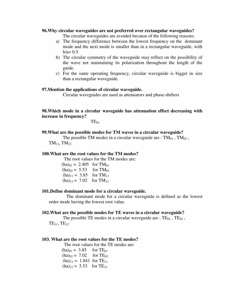
100.What are the root values for the TM modes?
The root values for the TM modes are:
(ha)01 = 2.405 for TM01
(ha)02 = 5.53 for TM02
(ha)11 = 3.85 for TM11
(ha)12 = 7.02 for TM12
101.Define dominant mode for a circular waveguide. The dominant mode for a circular waveguide is defined as the lowest
order mode having the lowest root value.
102.What are the possible modes for TE waves in a circular waveguide? The possible TE modes in a circular waveguide are : TE01 , TE02 ,
TE11, TE12
103. What are the root values for the TE modes?
The root values for the TE modes are:
(ha)01 = 3.85 for TE01
(ha)02 = 7.02 for TE02
(ha)11 = 1.841 for TE11
(ha)12 = 5.53 for TE12

104. What is the dominant mode for TE waves in a circular waveguide
The dominant mode for TE waves in a circular waveguide is the
TE11 because it has the lowest root value of 1.841
105. What is the dominant mode for TM waves in a circular waveguide
The dominant mode for TM waves in a circular waveguide is the
TM01 because it has the lowest root value of 2.405.
106. What is the dominant mode in a circular waveguide
The dominant mode for TM waves in a circular waveguide is the
TM01 because it has the root value of 2.405. The dominant mode for TE waves in
a circular waveguide is the TE11 because it has the root value of 1.841 .Since the
root value of TE11 is lower than TM01 , TE11 is the dominant or the lowest order
mode for a circular waveguide.
107. Mention the dominant modes in rectangular and circular waveguides
For a rectangular waveguide,
the dominant mode is TE01
For a circular waveguide,
the dominant mode is TE11
108.Why is TM01 mode preferred to the TE01 mode in a circular waveguide?
TM01 mode is preferred to the TE01 mode in a circular waveguide, since
it requires a smaller diameter for the same cut off wavelength.
109.What are the performance parameters of microwave resonator?
The performance parameters of microwave resonator are:
(i) Resonant frequency
(ii) Quality factor
(iii) Input impedance
110.What is resonant frequency of microwave resonator?
Resonant frequency of microwave resonator is the frequency at which the energy
in the resonator attains maximum value. i.e., twice the electric energy or magnetic
energy.
111.Define quality factor of a resonator.
The quality factor Q is a measure of frequency selectivity of the resonator.
It is defined as
Q = 2 ∏ x Maximum energy stored / Energy dissipated per cycle
= ω W/ P
Where W is the maximum stored energy

P is the average power loss
112.What is a resonator?
Resonator is a tuned circuit which resonates at a particular frequency at
which the energy stored in the electric field is equal to the energy stored in the magnetic
field.
113.How the resonator is constructed at low frequencies?
At low frequencies upto VHF ( 300 MHz) , the resonator is made up of
the reactive elements or the lumped elements like the capacitance and the inductance.
114.What are the disadvantages if the resonator is made using lumped elements at
high frequencies?
1) The inductance and the capacitance values are too small as the
frequency is increased beyond the VHF range and hence difficult to
realize .
115.What are the methods used for constructing a resonator?
The resonators are built by
a) using lumped elements like L and C
b) using distributed elements like sections of coaxial lines
c) using rectangular or circular waveguide
116.What is a transmission line resonator or coaxial resonator?
Transmission line resonator can be built using distributed elements like
sections of coaxial lines. The coaxial lines are either opened or shunted at the end
sections thus confining the electromagnetic energy within the section and acts as the
resonant circuit having a natural resonant frequency.
117.Why transmission line resonator is not usually used as microwave resonator?
At very high frequencies transmission line resonator does not give very
high quality factor Q due to skin effect and radiation loss. So, transmission line resonator
is not used as microwave resonator
118.What are cavity resonators?
Cavity resonators are formed by placing the perfectly conducting sheets on
the rectangular or circular waveguide on the two end sections and hence all the sides are
surrounded by the conducting walls thus forming a cavity. The electromagnetic energy is
confined within this metallic enclosure and they acts as resonant circuits .
119.What are the types of cavity resonators?
There are two types of cavity resonators. They are:
a ) Rectangular cavity resonator
b ) Circular cavity resonator
120.Why rectangular or circular cavities can be used as microwave resonators?
Rectangular or circular cavities can be used as microwave resonators because
they have natural resonant frequency and behave like a LCR circuit.
121.How the cavity resonator can be represented by a LCR circuit?
The electromagnetic energy is stored in the entire volume of the cavity in
the form of electric and magnetic fields. The presence of electric field gives rise to a
capacitance value and the presence of magnetic field gives rise to a inductance value and
the finite conductivity in the walls gives rise to loss along the walls giving rise to a
resistance value. Thus the cavity resonator can be represented by a equivalent LCR
circuit and have a natural resonant frequency
122.Name the three basic configurations of coaxial resonators.
The basic configurations of coaxial resonators are:
d) Quarter wave coaxial cavity
e) Half wave coaxial cavity
f) Capacitance end coaxial cavity
123.What is the dominant mode for rectangular resonator?
The dominant mode of a rectangular resonator depends on the
dimensions of the cavity.
For b<a<d, the dominant mode is TE101
124.What is the dominant mode for circular resonator?
The dominant mode of a circular resonator depends on the dimensions
of the cavity.
Ford< 2a, the dominant mode is TM010
125.When a medium is said to be free- space.
A free-space medium is one in which there are no conduction currents and no
charges.

16 MARKS QUESTIONS
1. Explain in detail about the waveform distortion. Derive the condition for a
distortion less line?
Waveform Distortion:
Signal transmitted over lines are normally complex and consists of many
frequency components. For ideal transmission, the waveform at the line-receiving end
must be the same as the waveform of the original input signal. The condition requires that
all frequencies have the same attenuation and the same delay caused by a finite phase
velocity or velocity of propagation. When these conditions are not satisfied, distortion
exists.
The distortions occurring in the transmission line are called waveform
distortion or line distortion. Waveform distortion is of two types:
a) Frequency distortion
b) Phase or Delay Distortion.
a) Frequency distortion: In general, the attenuation function α is a function of frequency.
Attenuation function specifies the attenuation or loss incurred in the line while the signal
is propagating. When a signal having many frequency components are transmitted along
the line, all the frequencies will not have equal attenuation and hence the received end
waveform will not be identical with the input waveform at the sending end because each
frequency is having different attenuation. This type of distortion is called frequency
distortion. That is, when the attenuation constant is not a function of frequency,
frequency distortion does not exist on transmission lines.
In order to reduce frequency distortion occurring in the line,
a) The attenuation constant α should be made independent of frequency.
b) By using equalizers at the line terminals which minimize the frequency
distortion. Equalizers are networks whose frequency and phase
characteristics are adjusted to be inverse to those of the lines, which result
in a uniform frequency response over the desired frequency band, and
hence the attenuation is equal for all the frequencies.
b) Delay distortion:
When a signal having many frequency components are transmitted along the
line, all the frequencies will not have same time of transmission, some frequencies
being delayed more than others. So the received end waveform will not be identical with
the input waveform at the sending end because some frequency components will be
delayed more than those of other frequencies. This type of distortion is called phase or
delay distortion. It is that type of distortion in which the time required to transmit the
various frequency components over the line and the consequent delay is not a constant.
This is, when velocity is independent of frequency, delay distortion does not exist on the
lines. In general, the phase function is a function of frequency. Since v= ω / β, it will be
independent of frequency only when β is equal to a constant multiplied by ω.

In order to reduce frequency distortion occurring in the line,
e) The phase constant β should be made dependent of frequency.
f) The velocity of propagation is independent of frequency.
g) By using equalizers at the line terminals which minimize the
frequency distortion. Equalizers are networks whose frequency and
phase characteristics are adjusted to be inverse to those of the lines,
which result in a uniform frequency response over the desired
frequency band, and hence the phase is equal for all the frequencies.
Therefore, we conclude that a transmission line will have neither delay nor frequency
distortion only if α is independent of frequency and β should be a function of frequency.
Distortion less line:
It is desirable, however to know the condition on the line parameters that
allows propagation without distortion. The line having parameters satisfy this condition is
termed as a distortion less line. A line, which has neither frequency distortion nor phase
distortion is called a distortion less line. The condition for a distortion less line was first
investigated by Oliver Heaviside.Distortionless condition can help in designing new lines
or modifying old ones to minimize distortion.
Condition for a distortion less line The condition for a distortion less line is
RC=LG. Also,
a) The attenuation constant α should be made independent of frequency.
α = RG
b) The phase constant β should be made dependent of frequency.
β = ω LC
c) The velocity of propagation is independent of frequency.
V=1 / LC
2. Explain in detail the different types of loading a cable? Derive the attenuation
and phase constant and velocity of propagation for a loaded cable.
Loading:
In ordinary telephone cables, the wires are insulated with paper and twisted
in pairs, therefore there will not be flux linkage between the wires, which results in
negligible inductance, and conductance. If this is the case, the there occurs frequency
and phase distortion in the line. For the telephone cable to be distortion less line, the
inductance value should be increased. Increasing the inductance by inserting inductors in
series with the line is termed as loading and such lines are called loaded lines. The
theory of loading was developed by Oliver Heaviside and Professor. M.I. Pupin
developed the practical method of loading.
In practice, lumped inductors, known as loading coils are placed at suitable
intervals along the line to increase the effective distributed inductance. So loading is the
process of increasing the inductance value by placing lumped inductors at specific
intervals along the line, which avoids the distortion.
Loading Coils:

The important aspect of a loading coil design is that saturation and stray
fields should be avoided. It should have a low resistance and should be of small size
particularly for the field work. It should maintain circuit balance. For this reason, the
coils are wound on toroidal cores( See figure from Umesh Sinha Book).These cores are
manufactured by permalloy or molybdenum-permalloy,ground to dust and then hold
together like shellac, so that there are a large number of air gaps to reduce the possibility
of saturation.
Types of Loading :
a) Continuous loading
b) Patch loading
h) Lumped loading
i) Continuous loading is the process of increasing the inductance value by placing a
iron core or a magnetic tape over the conductor of the line thus increasing the
permeability of the surrounding medium thereby increasing inductance. (Refer fig. From
Umesh Sinha Book)
Patch loading is the process of using sections of continuously loaded cables
separated by sections of unloaded cables that increases the inductance value.
Lumped loading is the process of increasing the inductance value by placing
lumped inductors at specific intervals along the line, which avoids the distortion.
Attenuation and phase constant for a loaded cable:
For a uniformly loaded cable,
a) The attenuation constant α is
α = ( R/2) * C/L
b) The phase constant β is
β = ω LC
c) The velocity of propagation is
V= 1 / LC
3. Derive the general solutions of transmission line

Defn: used for guiding electrical signals
Write the general solutions: the votage and current equation
4. Derive the input impedance of a transmission line. Also find the input
impedance of open and short circuited lines.
1.Input impedance is voltage divided by current
2.write the condition for a short circuited line and determine the input
impedance
3. write the condition for a open circuited line and determine the input
impedance
5. Derive the reflection loss of a transmission line
Reflection occurs because of the following cases:
1) when the load end is open circuited
2) when the load end is short-circuited
3) when the line is not terminated in its characteristic impedance
When the line is either open or short circuited, then there is not resistance at the
receiving end to absorb all the power transmitted from the source end. Hence all the
power incident on the load gets completely reflected back to the source causing
reflections in the line. When the line is terminated in its characteristic impedance, the
load will absorb some power and some will be reflected back thus producing reflections.
Reflection loss is defined as the number of nepers or decibels by which the
current in the load under image matched conditions would exceed the current actually
flowing in the load.
6. What are impedance matching devices.Write short notes on eighth line and half
line.
Answer:
The Eigthwave, half wave, quarter – wave line or transformer and the
tapered line are some of the impendence –matching devices.
Half wave line:
The expression for the input impendence of the line is given by
Zs = Zr
Thus the line repeats is terminating impedance .Hence it is operated as one to one
transformer .Its application is to connect load to a source where they can not be
made adjacent.
Eigth wave line:

An eighth wave line is used to transform any resistance to an impendence with a
magnitude equal to Ro of the line or to obtain a magnitude match between a
resistance of any value and a source of Ro internal resistance
7. Write short notes on quarter wave line and write its applications. Answer:
The expression for input impendence of a quarter wave line is given by
Zs = R02
Zr
Hence the quarter wave line is considered as a transformer to match impedances
Zr and Zs .It is used as a impendence matching section .
The important application of quarter wave line is to a couple a transmission line
to a resistive load such as antenna.
A short circuited quarter wave line can be used as an insulator to support an open
wire line or coaxial line conductor .
An important application of the quarter wave matching sectionis to a
couple a transmission line to a resistive load such as an antenna .The quarter –
wave matching section then must be designed to have a characteristic impendence
Ro so chosen that the antenna resistance Ra is transformed to a value equal to the
characteristic impendence Ra of the transmission line.The characteristic
impendence Ro of the matching section then should be
Ro’ = √ Ra Ro
8.Write short notes on exponential line for impedance transformation. The equations used for the design of the exponential line are :
L/L1 = ln(d/a)/ln(d1/a1)
Where, L is the inductance per meter of the line
L1 is the inductance per meter at the sending end.
9.Explain in detail about single stub matching.
Single stub matching is one in which single stub is placed in shunt with a
main transmission line to provide impedance matching
10.Explain in detail about double stub matching.
Another possible method of impedance matching is to use two stubs in
which the locations of the stub are arbitrary,the two stub lengths furnishing the
required adjustments.The spacing is frequently made λ/4.This is called double
stub matching.

11.Derive an expression for the voltage and current on the dissipation less line.
Answer:
Refer page No:285 (Text book)
12.Derive an expression for the input impedance under open and short circuited
condition.
Answer:
The input impedance of open aned short circuited lines are given by,
Zsc = jRo tan 2 πs
λ
13.Derive an expression for the input impedance of the dissipation less line.
Answer:
The input impedance of a dissimpationless line is given by,
Z s = Es = R0 1+ k < φφφφ -2ββββs
I s 1- k <φφφφ -2ββββs
14.What are standing waves? Derive the expression for standing wave Ratio.
Answer:
If the transmission is not terminated in its characteristic impedance ,then there
will be two waves traveling along the line which gives rise to standing waves
having fixed maxima and fixed minima.
The ratio of the maximum to minimum magnitudes of voltage or current on a
line having standing waves called standing waves ratio.
Emax Imin
S = =
Emin Imin
15. Derive the field component of the wave propagating between parallel planes?
• Definition for Parallel guide
• Expression for Ex,Ey,Hx,Hy
16. Derive the electromagnetic field expressions for TE waves guided by a parallel
conducting plane?
• Definition for TE waves
• Expression for Ey,Hx,Hz
17. Derive the electromagnetic field expressions for TM waves guided by a parallel
conducting plane?
• Definition for TM waves

• Expression for Ex,Ez,Hy
18. Derive the electromagnetic field expressions for TEM waves guided by a parallel
conducting plane?
• Definition for TEM waves
• Expression for Ex,Hy
19.Derive the field expressions for the field components of TM waves in a
rectangular waveguide
� For TM waves, Hz=0
� Substitute Hz=0 and find the field components Ey, Hx, Hy ,Ez , Ex
20.Derive the field expressions for the field components of TE waves in a
rectangular waveguide
� For TE waves, Ez=0
� Substitute Ez=0 and find the field components Ey, Hx, Hy ,Hz , Ex
