transmission therapy the 4l30e files - … this edition of transmission therapy, ... mp le u ti on...
TRANSCRIPT
26 GEARS August 2003
TRANSMISSION THERAPY
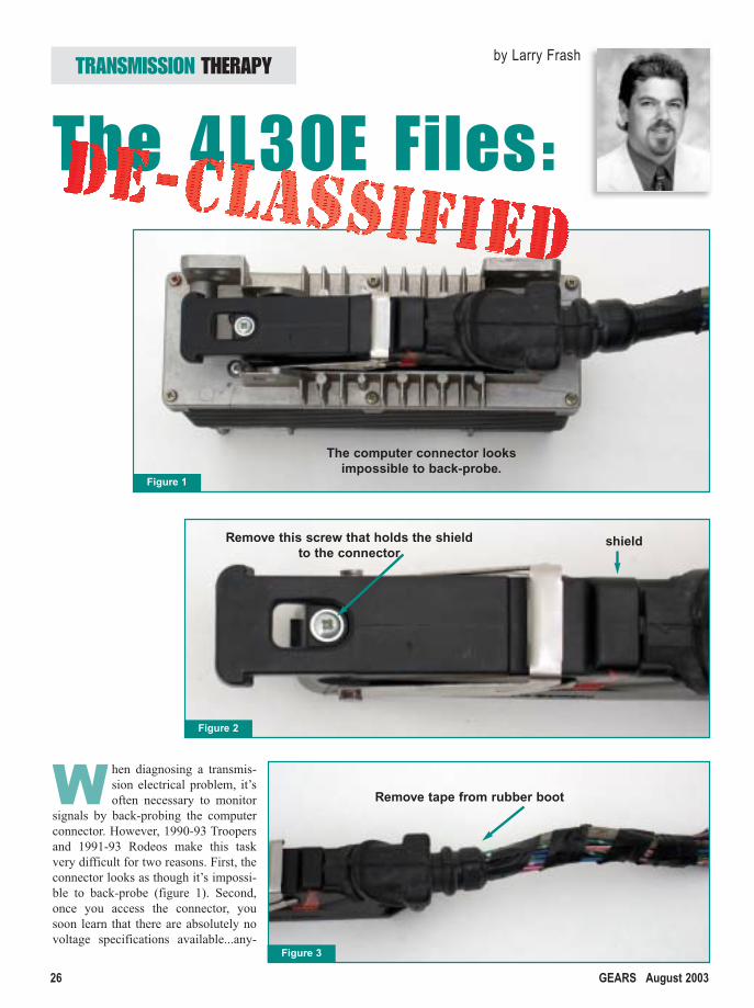
W hen diagnosing a transmis-sion electrical problem, it’soften necessary to monitor
signals by back-probing the computerconnector. However, 1990-93 Troopersand 1991-93 Rodeos make this taskvery difficult for two reasons. First, theconnector looks as though it’s impossi-ble to back-probe (figure 1). Second,once you access the connector, yousoon learn that there are absolutely novoltage specifications available...any-
by Larry Frash
Figure 1
Figure 2
Figure 3
The computer connector looks impossible to back-probe.
Remove this screw that holds the shieldto the connector
shield
Remove tape from rubber boot
The 4L30E Files:
trooper pooper3.qxd 7/10/03 4:02 PM Page 26

GEARS August 2003 27
where. This lack of information makesit very difficult to diagnose these vehi-cles. Even though these vehicles areover 10 years old, something had to bedone.
In this edition of TransmissionTherapy, we’ll show you how to accessthe computer connector and supply youwith the voltage specifications. Thisinformation is often useful when diag-nosing trouble codes and driveabilityproblems. Then we’ll cover coderetrieval and focus on the most com-mon solenoid codes.
Back-probing the ComputerThe first step when trying to back-
probe the computer connector is tolocate the computer: Look for it behindthe driver’s side of the dash, to the leftof the steering column. Then followthese easy steps:
• Unbolt the transmission com-puter from its bracket.
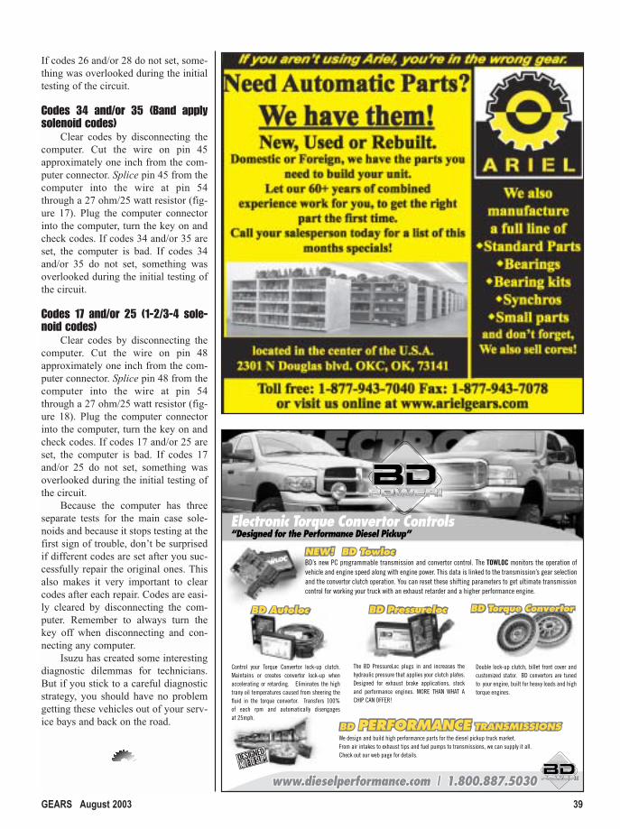
• Disconnect the computer andremove the screw that holdsthe shield to the connector(figure 2).
• Remove the tape from the rub-ber boot (figure 3) and slidethe shield up the harness andaway from the connector (fig-ure 4).
• Once you have the shieldremoved, plug the connectorback into the computer (figure5).
That solves the first problem: Nowyou can back-probe the computer con-nector.
Figure 6 shows the computer con-nector as viewed from the wire side.Figure 7 (page 30), lists the function ofeach pin, with the correct voltage val-ues.
Code Retrieval
90-91Look for a two pin diagnostic con-
nector, located under the dash, behindthe hood release. Ground the wire thatis yellow with a black stripe.
92-93Look for a three pin diagnostic
connector, located under the dash to the
left of the center console. Ground thewire that is yellow with a black stripe.
Some of these connectors are hardto find and often rest next to similar-looking connectors. If you can’t findthe diagnostic connector or aren’t surewhich one to use, you can simplyground pin 25 at the computer connec-tor on all 1990-93 models.
Reading Trouble Codes The “Check Trans” light will flash
the codes. The first set of flashes indi-cate the tens digits, a short pause andthen the ones digits. For example, todisplay a code 43, the computer wouldflash the “Check Trans” light fourtimes, a short pause, then flash threemore times. The computer will repeateach code three times, with a longpause between each code. Even withoutany problems, the first code will alwaysbe a code 12. This simply means thatthe computer is in diagnostic mode. Seefigure 8 (page 32), for a complete codelist.
1-2/3-4, 2-3 & Band ApplySolenoids system tests
We’ll call these three solenoids themain case solenoids. During initialstart-up, the computer runs the solenoidcircuits through a series of tests. Themain case solenoids must pass all threetests.
Test one:The computer checks for a short to
ground on pins 43, 45 and 48 (figure 9,page 32). If there is a short to ground onany of these three circuits, the comput-er will set solenoid shorted to groundcodes (17, 26 and/or 35), turn off allthree solenoid drivers (transistors in thecomputer) and stop testing. This willcause the transmission to be in failsafe.If all three circuits pass this test, thecomputer will go to test two.
Test two:The main case solenoids are sup-
plied ground from the computerthrough what we’ll call the groundrelay, located inside the computer (fig-ure 10, page 32). Before the computerturns the ground relay on, it monitorsthe solenoid side of the relay by pulsingthe three main case solenoid drivers on
trooper pooper3.qxd 7/10/03 4:02 PM Page 27

and off several times. Since the relay isopen, the computer expects to see thevoltage alternate 0-12-0-12… on pin54 (figure 11, page 32). If the comput-er only sees 12 volts (figure 12, page34), it knows there is either a short toB+ or one of the solenoid drivers isstuck on. If the computer only sees zerovolts on pin 54 (figure 13, page 34), itknows that either the circuit is shortedto ground, has an open in all three sole-noids or all three solenoid drivers arestuck off. In either of these situations,the computer will set a code 43 and notturn the relay on. Once a code 43 is setthe computer will also turn all threesolenoid drivers off and stop testing.Keep in mind, the computer only puls-es the solenoids for about 0.25 secondsduring this test and is best seen with anLED or an oscilloscope.
If the ground relay passes this test,the relay is turned on and suppliesground to the three main case solenoidsallowing test three to begin. Note:Because the computer stops monitoringthe ground circuit once the relay isturned on, a code 43 will not set afterthe initial test is complete, even if thereis an intermittent open in the groundcircuit.
Test three:Once the ground relay is closed
and supplies ground to the main casesolenoids, the computer can check foropen circuits and shorts to B+ on pins43, 45 and 48 (figure 14, page 34). Ifthere are, the computer will set sole-noid codes for open or shorted to B+(25, 28 and/or 34) and turn all threesolenoid drivers off. Keep in mind, ifthe ground relay contacts are burnt, thecomputer will think there is an open inall three main case solenoids.However, because the computer onlymonitors the solenoid side of theground relay (pin 54), it will not set acode 43 even though the ground relayis bad.
During normal operation, thecomputer is constantly checking forshorts to ground, open circuits andshorts to B+ on pins 43, 45 and 48. Ifany main case solenoid code is set, thecomputer will turn all three solenoiddrivers off and turn off the groundrelay.
DiagnosisTo diagnose any main case sole-
noid codes including code 43, discon-
nect the computer. With the key on,engine off, check for positive voltageon pins 43, 45, 48 and 54 and then
28 GEARS August 2003
Figure 4
Slide the shield up the harness andaway from the connectorconnector
1 2 3 4 5 6 7 8 9 10 11 12 13 14 15 16 17 18 19
20 21 22 23 24 25 26 27 28 29 30 31 32 33 34 35 36 37
38 39 40 41 42 43 44 45 46 47 48 49 50 51 52 53 54 55
Figure 5
Once you haveremoved theshield, plug theconnectorback into thecomputer.
Figure 6Connector viewed from the wire side.
The 4L30E Files: DE-CLASSIFIED
trooper pooper3.qxd 7/10/03 4:02 PM Page 28

M
a
k
e
T
h
e
S
h
i
f
t
T
o
.
.
.
M
a
k
e
T
h
e
S
h
i
f
t
T
o
.
.
.
M
a
k
e
T
h
e
S
h
i
f
t
T
o
.
.
.
M
a
k
e
T
h
e
S
h
i
f
t
T
o
.
.
.
THE SIMPLE SOLUTION
TRANSMISSION PARTS, INC.
SUPER
IOR
A DIVISIO
N OF SUPERIO
R TRANSMISSIO
N PARTS, IN
C.
THE SIMPLE SOLUTION
TRANSMISSION PARTS, INC.SUPERIOR
TM
Call For The DistributorNearest You: 800-451-3115
The Superior Ford E4OD/4R100 Tuff Pump
PUMPING OUT QUALITYPUMPS FOR 17 YEARSPUMPING OUT QUALITYPUMPS FOR 17 YEARSPUMPING OUT QUALITYPUMPS FOR 17 YEARS
Get Your Hands on Some Truly Superior
Pumps
Top quality materials, skilled craftsmen, and state-of-the art testing and inspection equipment all add up to a product we can stand
behind. Save time and money with Superior pumps.
This could very well be the "best pump in the business". Like all Superior products our 4L60 & 4L60E Pumps are quality built to exacting standards and bacKed by our Superior commitment to customer satisfaction.
Superior's rebuilt Tuff pumps deliver the following:
1. Each pocket custom cut to slide and rotor for proper clearance.
2. New bushings, seals, and O ring.
3. Drain back opened.
4. Modified converter clutch valve increases lube in lock-up.
5. Diamond machined surfaces.
6. Fully inspected.
7. Sealed Power unbreakable rings with 10 or 13 vane rotor.
8. New slide springs.
9. Conversion pumps available if core replacement is a problem.
10. Guaranteed for 90 days against front seal blowouts and ring breakage.
The Super Pump offers all the same features listed for the Tuff pump plus the follow added benefits:
1. Includes fully assembled pressure regulator valve train with .471 boost valve and Superior's own pressure regulator spring.
2. This pump is fully Dyno tested and packed for ready installation.
3. This pump has a 1 year Guaranty.
Tuff Pumps
Super Pumps
The E4OD/4R100 Tuff Pump is setting the standards.
Feature packed and dependable, the Superior
E4OD/4R100 Tuff Pump is the first choice for builders
coast to coast.
Superior’s fully rebuilt and modified pump is
completely ready to install.
Superior's E4OD/4R100 Tuff Pump includes the following
updates:
1. New high volume gear.
2. New Superior steel boost valve
3. Superior's proven pressure regulator spring.
4. Code 62 modification for better converter charge.
5. No walk bushing installed with drainback notched.
6. Full time lube.
Superior 4L60 & 4L60-E Pumps
29-Superior_8-03.qxd 7/11/03 4:56 PM Page 29

30 GEARS August 2003
PinFunction Condition Signal
1 A/C Request AC off 0 VAC on B+
2 Cruise Control3 N/A - -4 N/A - -5 N/A - -6 TPS Idle 0.5 V
Full Throttle 4.5 V7 Power Mode Indicator Not in Power Mode (Light Off) B+
In Power Mode (Light On) 0 V8 Range Selector Pin C Manual P, R & N 0 V
Manual D, 3, 2 & L B+9 N/A - -10 Winter Mode Indicator Not in Winter Mode (Light Off) B+
In Winter Mode (Light On) 0 V11 Engine RPM 91-92 Frequency varies with
Rodeo, 90-91 Trooper engine rpm12 N/A - -13 Diagnostic - -14 VSS Ground Always < 0.10 V15 Kickdown Switch All Except Full Throttle B+
Full Throttle 0 V16 Ground Always < 0.10 V17 Ground Always < 0.10 V18 Ground Always < 0.10 V19 Ground Always < 0.10 V20 VSS Signal Vehicle Stopped 0 V AC
Vehicle Moving > 0.5 VAC21 A/C Cut Relay22 Fluid Temp 32° F (0° C) 4.4 V
68° F (20° C) 3.6 V176° F (80° C) 1.0 V248° F (120° C) 0.4 V
23 Range Selector Pin A Manual N, D & L 0 VManual P, R, 3 & 2 B+
24 5 V Reference Voltage Key Off 0 VKey On 5 V
25 Diagnostic Enable Normal B+During Code Retrieval 0 V
26 Range Selector Pin B Manual P, 2 & L 0 VManual R, N, D & 3 B+
27 N/A - -28 Keep Alive Power Always B+29 Check Trans Indicator Check Trans Light Off B+
Check Trans Light On 0 V
PinFunction Condition Signal
30 Coolant Temp Engine Temp Cold B+Engine Temp Warm 0 V
31 Winter Mode Switch Switch Released B+Switch Depressed 0 V
32 N/A - -33 Range Selector Pin G Manual R, D & 2 0 V
Manual P, N, 3 & L B+34 Power Mode Switch Switch Released B+
Switch Depressed 0 V35 N/A - -36 Ground Always < 0.10 V37 Ignition Key Off 0 V
Key On B+38 TCC Solenoid Lockup Off 0 V
Lockup On B+39 Brake Switch Brake Pedal Released B+
Brake Pedal Depressed 0 V40 Force Motor High Minimum Pressure 1.0 Amp
Maximum Pressure 0.1 Amp41 Force Motor Low Minimum Pressure 1.0 Amp
Maximum Pressure 0.1 Amp42 N/A - -43 2-3 Solenoid Solenoid Off 0 V
Solenoid On B+44 N/A - -45 Band Apply Solenoid Not Active 0% duty
Active Approx 51%46 N/A - -47 N/A - -48 1-2 / 3-4 Solenoid Solenoid Off 0 V
Solenoid On B+49 N/A - -50 Barometric Sensor
(Some Models)
51 N/A - -52 N/A - -53 Reference Voltage Key Off 0 V
Key On 5 V54 Solenoid Ground Normal Operation 0 V
W/code 43, 17, 25, 26, 28, 34 or 35 B+55 Engine RPM Frequency varies with
93 Rodeo, engine rpm92-93 Trooper
Figure 7
The 4L30E Files: DE-CLASSIFIED
90-93 Isuzu Trooper/91-93 Rodeo Pin Charts
trooper pooper3.qxd 7/10/03 4:02 PM Page 30

The road to more profitable operation begins
with quality products — and outstanding customer service and
support from the H.E.L.C. Group.
Get the whole story at the TRANSMISSION 2003 EXPO in Booth #504. You’ll discover the
latest in everything from transmission/drive train testing to torque converter rebuilding.
4060 Dixon • Des Moines, IA • www.helc.netAd No. 102-03
We’ll see you down the road
THE GROUP
Dynamometer97000ECRH with TDAC Balancer HB-4000
Weld Aligner AWA-2002
Call 1-888-442-5546 forFREE Axi-Line and TCRS Info kits
Call 1-888-442-5546 forFREE Axi-Line and TCRS Info kits
Axi-LineElectronic Shift
31-Hicklin-HELC_0803-2.qxd 7/14/03 5:06 PM Page 31

check for continuity to chassis groundon the same pins. There should be novoltage and no ground on either ofthese pins. If there is, use the wire dia-gram in figure 9 to re-wire the circuitthat failed this test from the computer to
the main case solenoids.Next, check the resistance of each
of the main case solenoids using the
chart in figure 15, page 38. If one ormore of these circuits failed this test,you either have a bad solenoid or a bad
32 GEARS August 2003
17 1-2/3-4 Shift Solenoid shorted toground
21 TPS voltage too high (above4.9V)
22 TPS voltage too low (below0.06V)
23 Engine Coolant Switch voltagetoo high. Note: Code will set if engine is not at operating tem-perature after 20 minutes run-ning time.
25 1-2/3-4 Shift Solenoid open orshorted to B+
26 2-3 Shift Solenoid shorted toground
28 2-3 Shift Solenoid open or short-ed to B+
29 TCC Solenoid shorted to ground31 No Engine RPM signal (no signal
above 19 mph with TPS above12%)
32 Force Motor circuit open (currentless than 0.095A)
33 Force Motor circuit shorted to B+(current higher than 1.5A)
34 Band Apply Solenoid open orshorted to B+
35 Band Apply Solenoid shorted toground
36 TCC Solenoid open or shorted toB+
39 No VSS signal 41 Gear Ratio Error43 Ground Control Circuit open,
shorted to ground or shorted toB+
46 Down Shift Error48 Low Battery Voltage (below 9.0V
at TCM pin 37)49 High Battery Voltage (above 16V
at TCM pin 37)55 EPROM Failure (bad computer)56 Mode Switch input incorrect65 Transmission Temp Sensor cir-
cuit open66 Transmission Temp Sensor cir-
cuit shorted to ground77 Kickdown Switch shorted to
ground (stuck closed)82 Mode Switch input incorrect
Figure 8
The 4L30E Files: DE-CLASSIFIED
Trouble Codes
1-2/3-4 Sol
2-3 Sol
Band Apply Sol
Main Case Connector
C
A
D
BPin 45
Pin 48
Pin 43
Pin 54
CPU
Ground Relay Open
A B
CD
System Test 1
The computer checks for shortsto ground onPins 43, 45 and 48
Figure 9
1-2/3-4 Sol
2-3 Sol
Band Apply Sol
Main Case Connector
C
A
D
BPin 45
Pin 48
Pin 43
Pin 54
CPU
Ground Relay Open
A B
CD
Figure 10
The ground relay supplies a constant ground to the
solenoids only if the system passes all tests.
1-2/3-4 Sol
2-3 Sol
Band Apply Sol
Main Case Connector
C
A
D
BPin 45
Pin 48
Pin 43
Pin 54
CPU
Ground Relay Open
A B
CD
Figure 11
SystemTest 2
SystemTest 2continued
The computerpulses batteryvoltage (B+) topins 43, 45 and 48and monitorsthese pulses onpin 54.
trooper pooper3.qxd 7/10/03 4:03 PM Page 32

connection between the computer andthe solenoid. Re-wire and/or replacethe solenoid in the circuit that failed thetest as necessary. You may also have aproblem in the ground wire betweenpin 54 and the main case solenoids, orthe ground relay contacts are burnt.
If there is no voltage and noground on these pins, and the solenoidresistance readings are correct, there isa good chance that these codes arebeing caused by a bad computer. Usethe following tests to rule out a badcomputer.
Code 43 (Solenoid ground circuit)The computer only needs to see
the voltage pulse from one of the maincase solenoids, so testing this circuit isactually simple. Clear any codes bydisconnecting the computer. Cut thewires on pins 48 and 54 approximatelyone inch from the computer connector.Connect the two wires from the com-puter through a 27 ohm/25 watt resis-tor. Plug the computer connector intothe computer, turn the key on andcheck codes. If code 43 is set, the com-puter is bad. If code 43 does not set,something was overlooked during theinitial testing of the circuit.
Codes 26 and/or 28 (2-3 solenoidcodes)
Clear codes by disconnecting thecomputer. Cut the wire on pin 43approximately one inch from the com-puter connector. Splice pin 43 from thecomputer into the wire at pin 54through a 27 ohm/25 watt resistor (fig-ure 16, page 38). Plug the computerconnector into the computer, turn thekey on and check codes. If codes 26and/or 28 are set, the computer is bad.
34 GEARS August 2003
The 4L30E Files: DE-CLASSIFIED
1-2/3-4 Sol
2-3 Sol
Band Apply Sol
Main Case Connector
C
A
D
BPin 45
Pin 48
Pin 43
Pin 54
CPU
Ground Relay Open
A B
CD
If the computer sees zero volts all the time during this test, it knows thereis either a short to ground, open in all three solenoids or all three sole-noid drivers are stuck off.
Figure 13
SystemTest 2continued
1-2/3-4 Sol
2-3 Sol
Band Apply Sol
Main Case Connector
C
A
D
BPin 45
Pin 48
Pin 43
Pin 54
CPU
Ground Relay Open
A B
CD
Figure 14
1-2/3-4 Sol
2-3 Sol
Band Apply Sol
Main Case Connector
C
A
D
BPin 45
Pin 48
Pin 43
Pin 54
CPU
Ground Relay Open
A B
CD
Figure 12
SystemTest 2continued
If the computer sees B+ on pin 54 all the time duringthis test, it knows there is either a short to B+ or one ofthe solenoid drivers are stuck on.
System Test 3
If system tests 1 and 2 pass, theground relay isclosed and suppliesa constant groundto the solenoids.Once the relay isclosed, the comput-er begins test 3 tocheck for open circuits and shortsto B+.
The computer only needs to
see the voltage pulse from
one of the main case sole-
noids, so testing this circuit
is actually simple.
trooper pooper3.qxd 7/10/03 4:03 PM Page 34

September 18-21, 2003
Nashville, Tennesse
e
To Register:1-800-428-8489 or
1-805-604-2000
35-EXPO_AD1.qxd 7/8/03 10:35 AM Page 35

®
© 2003 Ford Motor Company
Nothingfits like
Motorcraft.
When a Ford, Lincoln or Mercury comes into your shop, choose Motorcraft.® Why?
■ Remanufactured to exacting OE standards using highest-quality cores
■ Assemblies ready to install — higher productivity for your business
■ Complete overhaul kits also available using OE components
■ Nationwide availability through Dealerships and Distributors
■ Warranties up to 36 months/36,000 miles*
■ Competitive pricing
That’s an unbeatable value. And it’s just part of our commitmentto service, support and supply you better than ever. Give yourcustomers what they really want, OE performance by Motorcraft.®
Visit Motorcraft.com for technical resources,product information and purchase locations.
*See Dealership or distributor for copy of the limited warranty.
“I trust Motorcraft® every week, and so should you.”
– Ricky Rudd
Get the transmissionsdesigned,engineered and recommended byFord Motor Company.Get Motorcraft.®
36-motorcraft 8-03.qxd 7/10/03 2:49 PM Page 36

Here’s your chance to show the world that you’re the top dog! How? Enter the Top Tech Challenge. You’ll match skills with your fellowtechs by troubleshooting and assembling a Ford Motor Company transmission – while blindfolded. Can you do it? There’s just one way tofind out – call 1-888-213-2107 to register for a chance to compete. Or visit www.motorcraft.com and get the info for your Top Tech Challenge! You could win a 42" plasma TV, a $1,000 Snap-on® gift certificate, or othergreat prizes! Hurry, spaces are limited – registration ends August 30, 2003.
• Powertrain Industry Expo • September, 19-20, 2003 • Booth #1015
T P TECHC H A L L E N G E
Don’t miss your chance! Call 1-888-213-2107 or visit www.motorcraft.com today!©2003 Ford Motor Company
37-motorcraft 8-03.qxd 7/10/03 2:51 PM Page 37

38 GEARS August 2003
Computer Pins Solenoid ResistanceConnect ohm meter between pins 43 & 54 2-3 Shift Solenoid 17-24 ohmsConnect ohm meter between pins 45 & 54 Band Apply Solenoid 9-14 ohmsConnect ohm meter between pins 48 & 54 1-2/3-4 Shift Solenoid 17-24 ohms
Figure 15
Main case solenoid resistance chart
1-2/3-4 Sol
Computer
Pin 54
Pin 48
Cut pin 48 approximately one inch from the computer connector.
Splice pin 43 into the wire at pin 54 through a 27 ohm/25 watt resistor.
Figure 18
Band Apply Sol
Computer
Pin 54
Pin 45
Cut pin 45 approximately one inch from the computer connector.
Splice pin 43 into the wire at pin 54 through a 27 ohm/25 watt resistor.
Figure 17
2-3 Sol
Computer
Pin 54
Pin 43
Cut pin 43 approximately one inch from the computer connector.
Splice pin 43 into the wire at pin 54 through a 27 ohm/25 watt resistor.
Figure 16
The 4L30E Files: DE-CLASSIFIED
trooper pooper3.qxd 7/10/03 4:03 PM Page 38
GEARS August 2003 39
If codes 26 and/or 28 do not set, some-thing was overlooked during the initialtesting of the circuit.
Codes 34 and/or 35 (Band applysolenoid codes)
Clear codes by disconnecting thecomputer. Cut the wire on pin 45approximately one inch from the com-puter connector. Splice pin 45 from thecomputer into the wire at pin 54through a 27 ohm/25 watt resistor (fig-ure 17). Plug the computer connectorinto the computer, turn the key on andcheck codes. If codes 34 and/or 35 areset, the computer is bad. If codes 34and/or 35 do not set, something wasoverlooked during the initial testing ofthe circuit.
Codes 17 and/or 25 (1-2/3-4 sole-noid codes)
Clear codes by disconnecting thecomputer. Cut the wire on pin 48approximately one inch from the com-puter connector. Splice pin 48 from thecomputer into the wire at pin 54through a 27 ohm/25 watt resistor (fig-ure 18). Plug the computer connectorinto the computer, turn the key on andcheck codes. If codes 17 and/or 25 areset, the computer is bad. If codes 17and/or 25 do not set, something wasoverlooked during the initial testing ofthe circuit.
Because the computer has threeseparate tests for the main case sole-noids and because it stops testing at thefirst sign of trouble, don’t be surprisedif different codes are set after you suc-cessfully repair the original ones. Thisalso makes it very important to clearcodes after each repair. Codes are easi-ly cleared by disconnecting the com-puter. Remember to always turn thekey off when disconnecting and con-necting any computer.
Isuzu has created some interestingdiagnostic dilemmas for technicians.But if you stick to a careful diagnosticstrategy, you should have no problemgetting these vehicles out of your serv-ice bays and back on the road.
trooper pooper3.qxd 7/10/03 4:03 PM Page 39