transmission values: what to look for… in order to look
TRANSCRIPT
Y.M.WP.Transmission Values By Joe DeMonte 7.11.12 v1
Transmission Values: What to Look For… in Order to Look Through!
By Joe DeMonte
ASNT/PdM Thermal Infrared Level III
Purpose: The purpose of this paper is to educate on the subjects of:
1. Transmission values for infrared windows: Does a high value equal more accuracy?
Or, is knowing the percentage of transmission more important?
2. Transmission values for infrared windows: How does a “grill” effect transmission?
Will it make quantitative thermography null and void?
Tested Components: One electrical lug and one hot plate heated to steady state conditions. One
polymer infrared window with a mesh style safety guard and one crystal calcium fluoride (CaFl)
infrared window. One generic plastic garbage bag. One stainless steel cup filled with water and
heated to steady state conditions.
Tools Used During the Test: FLIR E50 thermal imager, thermometer
Definitions:
Transmission, transmissivity: The ability of light in the specified wavelength to pass through an
object. Example: visible light through a pane of glass, LW infrared light through a polymer infrared
window.
Thermography: is a technology that creates and analyzes images by detecting the heat radiating from
an object.
Quantitative Thermography: Analyzing thermal images by acquiring temperature values.
Qualitative Thermography: Analyzing thermal images without acquiring temperature values.
Steady State Conditions (Heat Transfer): When heat transfer is occurring while the temperature of
the objects involved do not change.
LW/Long Wave/8-12um: The waveband of most modern infrared maintenance cameras. The metric
unit micrometer/micron/um is used to measure the wavelength.
Non-Gray/Selective Radiator: Most substances and materials will not keep the same value of
transmission, reflection, and emission throughout the light spectrum. This may result in different
thermography cameras obtaining different results when measuring the same material.

Y.M.WP.Transmission Values By Joe DeMonte 7.11.12 v1
Introduction:
As an active thermographer and instructor for Infrared courses, I’ve always considered
infrared windows as an exciting technology. In the 90’s, there weren’t many choices when talking
about IR windows. Nowadays, we have several. I will cover two major materials used in modern
infrared windows: polymers and fluoride crystals. Both have value for the particular band width
(referred to as LW/Long Wave/8-12um) of infrared cameras that 99% of the thermographers use
during condition based monitoring.
Recently, I have been made aware of a rumor that polymer windows affixed with a mesh style
safety guard cannot be used for accurate quantifiable temperature measurements. I had not
considered this as an issue during my role as a thermographer or heard of it as an issue from the
100’s of electricians that ran our infrared program for TEGG Corporation around the globe. I decided
that I had better double check our methods and see for myself if I had been doing things incorrectly
for years.
Test Parameters
In order to measure transmission through a material, I will propose two procedures. We have
to remember that the results of the tests may not apply to other cameras even with the same
wavelength filters. This is primarily due to inconsistencies of detector response curves across the
waveband being used and the non-gray “selective radiator” effects of most materials in that
waveband.
Our transmissivity procedures:
• How to Measure Transmittance with a radiometric (temperature measuring) thermal imager:
1. Set your thermal imager up to measure “apparent temperatures” with e = 1.00 and
distance (if you have that setting) to 0. Also, external window optics should be off or
100%.
2. Heat up a metal target with a high emissivity target (electrical tape will work) affixed to
it to a steady state condition. I would recommend at least 30°C above reflected
temperatures.
3. Measure and set reflected apparent temperature.
4. Measure target without the IR window. Note the temperature.
5. Measure target with window in place.

Y.M.WP.Transmission Values By Joe DeMonte 7.11.12 v1
6. Adjust emissivity to set the camera temperature equal to the original temp without
the window. This is NOT the emissivity measurement of your window. We are using
the camera’s emissivity as a “loss” calculation and calculating the losses through the
window. The emissivity value you arrive at to reach the original directly viewed target
temperature equates to the transmission of the IR window.
OR
1. For cameras that have EXTERNAL OPTICS TRANSMISSION, this procedure is a little bit
more accurate. Heat up a metal target with a known emissivity target affixed to it.
About 30°C or more above reflected temperature is desirable.
2. Measure the actual temperature of the target. Example: with electrical tape, set e =
0.95 and measure and set Reflected Apparent Temperature. Note the temperature.
3. Measure target with window in place.
4. Adjust external window optics temperature to the temperature of the window (the
window is best kept at room temperature).
5. Adjust external window optics transmission until you reach the actual temperature of
the target as measured without the window in place. The value of transmissivity that
you arrive at to achieve the original temperature is the transmissivity of the IR
window.

Y.M.WP.Transmission Values By Joe DeMonte 7.11.12 v1
Question 1: Does a high value equal more accuracy? Or, is knowing the percentage of transmission
more important?
I will compare the results of a household garbage bag to a industrial strength polymer infrared
window and a crystal window. The polymer window should have a lower transmission value due to
the thickness/type of polymer and the reinforcing safety grill. The garbage bag should be relatively
high. The crystal will be lower than the garbage bag.
Here are the results:
Item Name Directly Viewed Parameters
Electric lug
Directly
viewed.
A r1:max 87.8
18.4
86.7 °C
50
Max Temperature 87.8 °C
External Optics Transmission 1.00
External Optics Temperature 21.0 °C
Emissivity 0.95
Electric lug
Viewed
through
polymer
window
A r1:max 55.5
21.1
55.5 °C
40
Max Temperature 55.5 °C
External Optics Transmission 1.00
External Optics Temperature 21.0 °C
Emissivity 0.95
Electric lug
Adjusted for
transmission
A r1:max 87.5
21.2
87.4 °C
50
Max Temperature 87.5 °C
Emissivity 0.95
External Optics Transmission 0.46
External Optics Temperature 21.0 °C
From the tests above, the 3” round polymer infrared window with a safety grid has a transmissivity of
0.46. Applying that result to an entirely different target and checking that result to a contact
thermometer, we find the following:

Y.M.WP.Transmission Values By Joe DeMonte 7.11.12 v1
SS Cup
Viewed
Directly A r1:max 70.4
18.9
76.3 °C
50
Emissivity 0.95
External Optics Transmission 1.00
External Optics Temperature 21.0 °C
Ar1 Max. Temperature 70.4 °C
SS Cup
Viewed
through IR
polymer
window
A r1:max 70.0
22.4
75.3 °C
40
60
Emissivity 0.95
External Optics Transmission 0.46
External Optics Temperature 21.0 °C
Ar1 Max. Temperature 70.0 °C
Visual
picture of
the
thermometer
A physical reading of approximately 157°F,
which converts to: 69.44°C. Well within
the accuracy of a radiometric thermal
imager.
My initial findings were that it appears we can use the known transmission value, even though it is
only 46%, and continue to perform quantitative thermography. Will this be the transmissivity value
that all infrared cameras measure through this style IR window? Absolutely not! Perhaps this was
the fact that led to some of the confusion in the industry.

Y.M.WP.Transmission Values By Joe DeMonte 7.11.12 v1
On to the plastic garbage bag….
Test Object
Directly
Viewed. A r1:max 90.8
19.4
90.6 °C
40
60
80
Emissivity 0.95
External Optics
Transmission
1.00
External Optics
Temperature
21.0
°C
Ar1 Max. Temperature 90.8
°C
Test Object
Viewed
Through a
Single Ply
Garbage
Bag
A r1:max 81.1
20.1
80.7 °C
40
60
80
Emissivity 0.95
External Optics
Transmission
1.00
External Optics
Temperature
20.5
°C
Ar1 Max. Temperature 81.1
°C
Test Object
Viewed
Through a
Single Ply
Garbage
Bag with
Trans.
Adjusted.
A r1:max 90.9
19.9
90.7 °C
40
60
80
Emissivity 0.95
External Optics
Transmission
0.83
Max Temperature 90.9
°C
Min Temperature 19.8
°C
The test on the single ply garbage bag with the 90°C target shows a transmission measurement of
0.83 or 83%. We will change out the target to a metal cup with heated water and check the results
with our same thermometer for accuracy.

Y.M.WP.Transmission Values By Joe DeMonte 7.11.12 v1
Stainless
Steel cup
with hot
water
viewed
directly.
A r1:max 69.6
19.6
69.5 °C
40
60
Emissivity 0.95
External Optics
Transmission
1.00
External Optics
Temperature
20.5
°C
Ar1 Max.
Temperature
69.6
°C
Object
viewed
through a
single ply
garbage
bag.
A r1:max 62.2
20.4
62.0 °C
30
40
50
60
Emissivity 0.95
External Optics
Transmission
1.00
External Optics
Temperature
20.5
°C
Ar1 Max.
Temperature
62.2
°C
Object
viewed
through a
single ply
garbage bag
with
transmission
adjusted.
A r1:max 69.3
20.3
69.1 °C
40
60
Emissivity 0.95
External Optics
Transmission
0.83
External Optics
Temperature
21.0
°C
Ar1 Max.
Temperature
69.3
°C
It appears that the original value of 0.83 transmission for the garbage bag holds after looking at a
different temperature object. It is a high value of transmission, but doesn’t give us any more
accuracy when performing thermography over the lower value (0.46) of the polymer/mesh window.
In other words, know the value of your window with regards to your thermal imager and don’t
worry about how high the value is.

Y.M.WP.Transmission Values By Joe DeMonte 7.11.12 v1
I will now test the crystal window. It has a viewing diameter of 68mm with a thickness of 2mm.
Using the same two heated targets, here are the results:
Test object
directly
viewed. A r1:max 90.8
19.4
90.6 °C
40
60
80
Emissivity 0.95
External Optics
Transmission
1.00
External Optics
Temperature
20.5
°C
Ar1 Max. Temperature 90.8
°C
Object
viewed
through
2mm thick
crystal
window.
A r1:max 55.4
20.7
55.2 °C
40
Emissivity 0.95
External Optics
Transmission
1.00
External Optics
Temperature
20.5
°C
Ar1 Max. Temperature 55.4
°C
Object
viewed
through
2mm thick
crystal
window
with trans
adjusted.
A r1:max 91.1
20.4
90.7 °C
40
60
80
Emissivity 0.95
External Optics
Transmission
0.43
External Optics
Temperature
21.0
°C
Ar1 Max. Temperature 91.1
°C
The crystal window has a transmission percentage of 0.43 or 43%. A little lower than the polymer
stacked with the mesh on this temperature target. I will now look at the cooler target, the hot water
in the stainless steel cup with electrical tape affixed to it.

Y.M.WP.Transmission Values By Joe DeMonte 7.11.12 v1
Stainless steel
cup with
electrical tape
viewed directly.
A r1:max 69.6
19.6
69.5 °C
40
60
Emissivity 0.95
External Optics
Transmission
1.00
External Optics
Temperature
20.5
°C
Ar1 Max. Temperature 69.6
°C
Stainless steel
cup viewed
through a 2mm
thick crystal
window.
A r1:max 45.2
21.2
45.1 °C
30
40
Emissivity 0.95
External Optics
Transmission
1.00
External Optics
Temperature
20.5
°C
Ar1 Max. Temperature 45.2
°C
Stainless steel
cup viewed
through a 2mm
thick crystal
window with
trans adjusted.
A r1:max 69.7
21.6
69.5 °C
40
60
Emissivity 0.95
External Optics
Transmission
0.45
External Optics
Temperature
21.0
°C
Ar1 Max. Temperature 69.7
°C
At a transmission of 0.45 or 45%, we do obtain a slightly different value of transmission in order to
match the directly viewed result.
Fluoride crystals are very “non-gray” to the majority of thermal infrared cameras used by
thermographers (a concept that has been documented in many papers). This means that the
temperature of the viewed object will cause the perceived transmission through the crystal to change

Y.M.WP.Transmission Values By Joe DeMonte 7.11.12 v1
when using long wave infrared cameras. When we are trying to measure the temperature of an
unknown object, such as found inside electrical cabinets, we cannot know the exact transmission
value to use in the camera. Because the actual value of transmission, not how high the value is,
controls our quantitative thermographic accuracy, we normally cannot achieve accurate
measurements or accurate differentials between two objects through that type of material.
I will show one more example of a high temperature target and the polymer and crystal to further the
experiment on transmissivity values.
Hot plate
viewed
directly. A r1:max 148.7
22.3
148.2 °C
50
100
Emissivity 0.95
External Optics
Transmission
1.00
External Optics
Temperature
20.5 °C
Ar1 Max. Temperature 148.7
°C
Hot plate
viewed
through the
polymer/mesh
window.
A r1:max 149.0
25.8
147.8 °C
50
100
Emissivity 0.95
External Optics
Transmission
0.46
External Optics
Temperature
21.0 °C
Ar1 Max. Temperature 149.0
°C
Hot plate
viewed
through the
2mm crystal
window.
A r1:max 156.3
23.8
155.6 °C
50
100
150
Emissivity 0.95
External Optics
Transmission
0.43
External Optics
Temperature
21.0 °C
Ar1 Max. Temperature 156.3
°C

Y.M.WP.Transmission Values By Joe DeMonte 7.11.12 v1
If I dial in the original 46% transmission value for the polymer/mesh window, I get the correct
temperature (within the IR camera manufacturer specification). The crystal is a bit off and will
continue to be further away from the actual temperature as the object’s temperature changes.
Question Number 2: How does a “grill/mesh” affect transmissivity? Can I get accurate results
through an IR window that has a safety “grill/mesh” installed?
So far, our experiment has used a polymer window with a grill/mesh. When the infrared camera is
place up close to the mesh, the camera can focus beyond the mesh and was able to obtain
consistency. I personally use the area max measurement function when viewing targets through IR
windows and directly viewed targets to keep consistency. Some instances dictate that I use a single
point temperature spot, and I prefer infrared cameras that can do both for flexibility.
To perform this experiment, let’s start by considering the grill. In my experience looking through
infrared windows installed in electrical cabinets, I find that the best/widest field of view is when the
infrared camera is close to the window. The mesh, when installed, will be out of focus and not look
like a mesh on the image. It will affect transmissivity values by lowering them, but again, we are not
so much concerned with a lower value. Even when using a non-mesh window such as a crystal,
normal operation will have the infrared camera closer to the window for a wider field of view into the
cabinet (see the following visual example). There is no need to have different procedures between
the two types of windows (mesh or non-mesh) based on this consideration.
Panel is 20” from the front of the IR/digital
camera. Crystal IR window is placed up against
the IR/digital camera. Overall FOV of the panel
is relatively wide.
Panel is 20” from the front of the IR/digital
camera. Crystal window is 6” from the front of
the IR/digital camera. Overall FOV of the panel
is down by at least ½.
Y.M.WP.Transmission Values By Joe DeMonte 7.11.12 v1
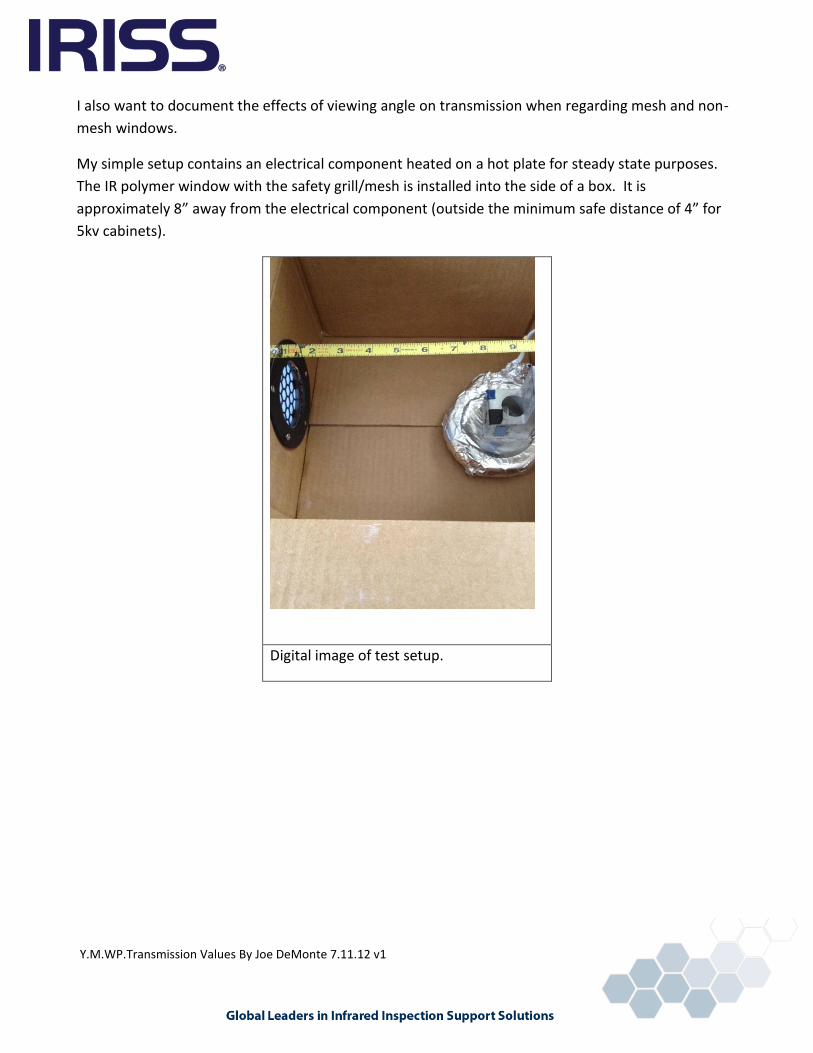
I also want to document the effects of viewing angle on transmission when regarding mesh and non-
mesh windows.
My simple setup contains an electrical component heated on a hot plate for steady state purposes.
The IR polymer window with the safety grill/mesh is installed into the side of a box. It is
approximately 8” away from the electrical component (outside the minimum safe distance of 4” for
5kv cabinets).
Digital image of test setup.
Y.M.WP.Transmission Values By Joe DeMonte 7.11.12 v1
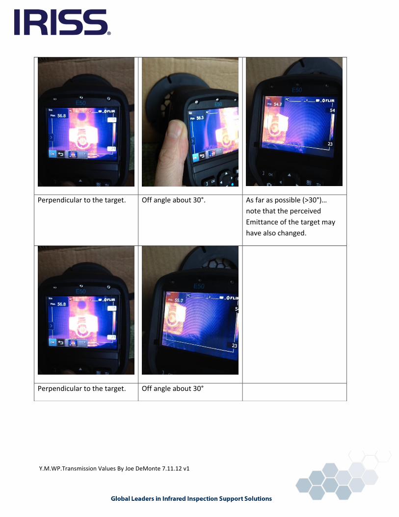
Perpendicular to the target. Off angle about 30°. As far as possible (>30°)…
note that the perceived
Emittance of the target may
have also changed.
Perpendicular to the target. Off angle about 30°

Y.M.WP.Transmission Values By Joe DeMonte 7.11.12 v1
The same concept using a crystal window without a safety mesh/grill:
90° to the target. Rotated about 30° to the
target.
Rotated > 30° to the target.
Emittance may have been
affected due to the angle.
It appears that we have near identical effects from both the polymer with mesh/grill and crystal
windows. It may be the foreshortening of the angle to the grill for the polymer window, and it may
be due to the increased thickness of the crystal being viewed through for the crystal window.
Another possibility is that the overall Emittance of the target will change with angle and for the
electrical tape, it will lower as you approach 45° and beyond towards parallel with the surface.

Y.M.WP.Transmission Values By Joe DeMonte 7.11.12 v1
Summary: In the field, a thermographer is always going to move the camera slightly to obtain the
best picture. I would always recommend this regardless of whether you are looking through a
transmissive material or directly at the target. Consider your infrared window materials carefully and
check your sources. I have personally heard seasoned thermographers make statements that a grill
or mesh will not allow for accurate temperatures. Or that the higher the transmission, the better the
window. In our study, we have determined that both of the tested material windows have similar
transmission values for our specific infrared camera (2011 FLIR E50). The crystal window will vary the
transmission as the temperature of the object changes.
If a thermographer decides to back the camera away from the infrared window in his/her surveys, the
mesh may not affect the transmission that the camera “sees” through the window. The transmission
values will be much higher (again, knowing the value is important, not how high the value is), but are
still measureable as long as the openings of the mesh are not smaller than the overall
IFOVmeasureable (also known as Spot Size Ratio) of your specific camera. I would not recommend
this only because of the much smaller overall field of view you will have during your inspections
versus being close to the infrared window.