transnet utility products catalogue
DESCRIPTION
ÂTRANSCRIPT
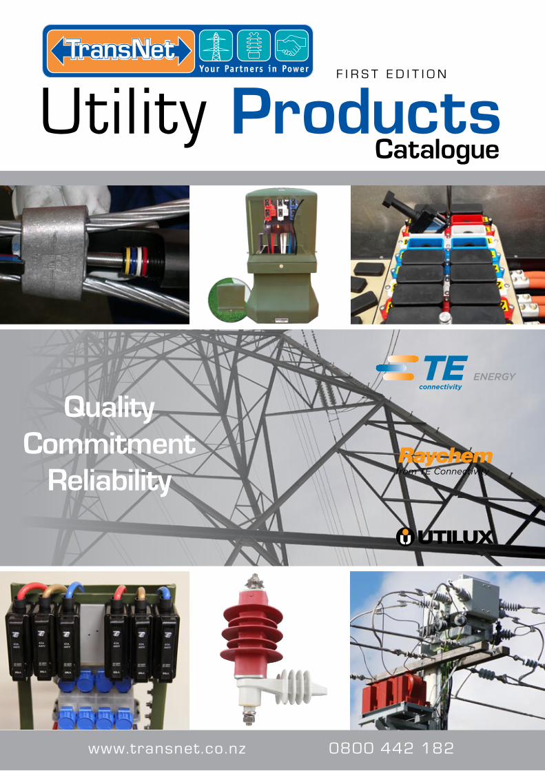
Quality Commitment
Reliability
Utility Products F I R S T E D I T I O N
Catalogue
www.transnet.co.nz 0800 442 182
TRANSNET NEW ZEALAND LIMITED DISCLAIMER
TransNet New Zealand Limited
Quality Commitment Reliability
TransNet NZ Limited has made every reasonable effort to ensure the accuracy of this information and it is, to the best of our knowledge, correct and reliable. Under no circumstances does this constitute an assurance of any particular quality or performance and users should independently evaluate the suitability of product for the desired application. All information in this publication including pricing, drawings, illustrations,
images and graphic designs are reflections of our current understanding. TransNet NZ Limited reserves the right to make any adjustment to this information at any time. Our liability for the products outlined in this catalogue is set forth in our standard terms and conditions of trade. In case of any potential ambiguities or questions, please contact us for clarification.
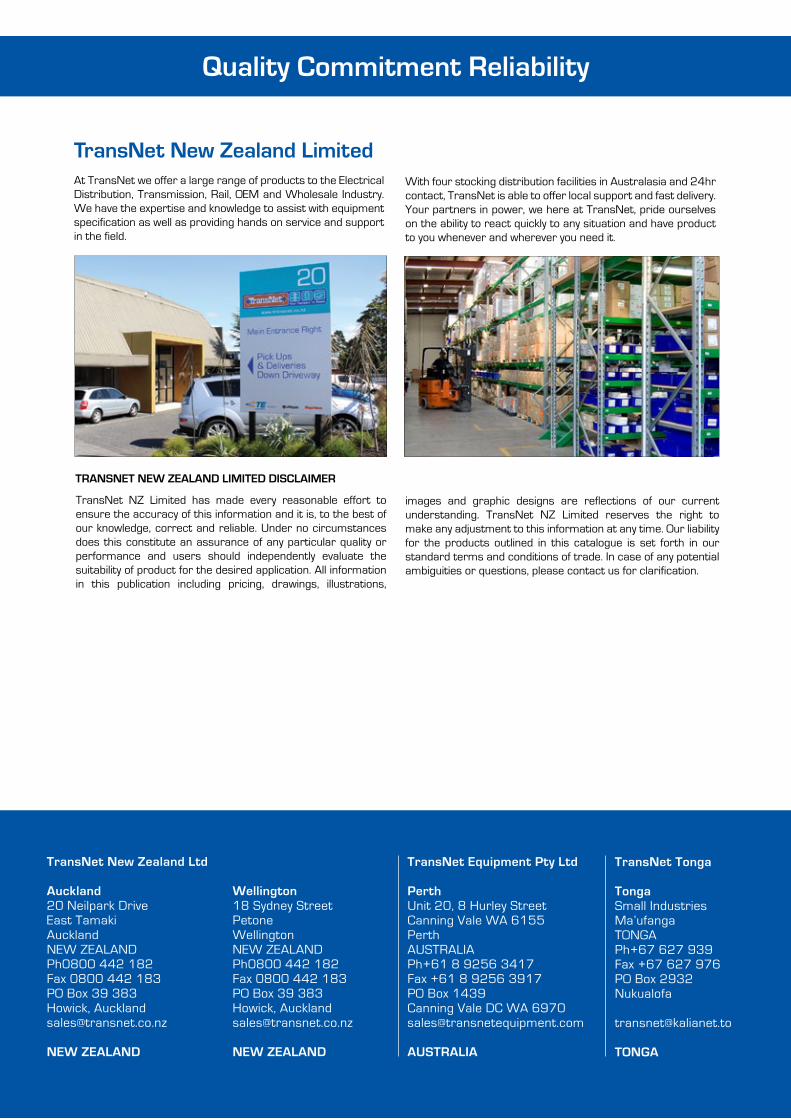
At TransNet we offer a large range of products to the Electrical Distribution, Transmission, Rail, OEM and Wholesale Industry. We have the expertise and knowledge to assist with equipment specification as well as providing hands on service and support in the field.
With four stocking distribution facilities in Australasia and 24hr contact, TransNet is able to offer local support and fast delivery. Your partners in power, we here at TransNet, pride ourselves on the ability to react quickly to any situation and have product to you whenever and wherever you need it.
Wellington18 Sydney StreetPetoneWellingtonNEW ZEALAND Ph0800 442 182Fax 0800 442 183PO Box 39 383 Howick, [email protected]
NEW ZEALAND
TransNet New Zealand Ltd Auckland20 Neilpark DriveEast TamakiAucklandNEW ZEALAND Ph0800 442 182 Fax 0800 442 183PO Box 39 383 Howick, [email protected]
NEW ZEALAND
TransNet Equipment Pty Ltd Perth Unit 20, 8 Hurley StreetCanning Vale WA 6155PerthAUSTRALIA Ph+61 8 9256 3417Fax +61 8 9256 3917PO Box 1439Canning Vale DC WA [email protected] AUSTRALIA
TransNet Tonga TongaSmall IndustriesMa’ufangaTONGA Ph+67 627 939Fax +67 627 976 PO Box 2932Nukualofa [email protected] TONGA
0800 442 182
1
CONTENTSCONNECTORS – Lugs & Links, Overhead Connectors, Mechanical Connectors etc... 3
HEATSHRINK PRODUCTS – Tubing, Tape, Busbar Insulation etc... 51
LV CABLE ACCESSORIES – Joints, Terminations and Accessories 67
MV CABLE ACCESSORIES – Joints, Terminations, Switchgear Connections etc... 83
ASSET PROTECTION & INSULATING COVERS – Retrofit Contact Insulation 109
CABLE GLANDS & DUCT SEALS – Nylon, Metal, CCG, RDSS, Duct Plugs etc... 113
HELICAL LINE FITTINGS – Deadends, Line Guards, Armour Rods etc... 123
LV ABC PRODUCTS – Suspension & Strain Clamps, Hook Bolts, Weak Links etc... 143
HV ABC PRODUCTS – Strain, Suspension & Stringing Products 153
LINE HARDWARE – Galvanised Fittings, Pole Bracing Blocks, Spreader Rods etc... 159
INSULATORS – Porcelain, Polymer, Stand Offs, Pin, Post etc... 181
CIRCUIT PROTECTION & FUSES – Fuses, Surge Arrestors, F.P.I's, MV Switchgear 203
PILLARS & PITS – TUDS and ECOPillar 229
EARTHING – Bolted, Wedge, Exothermic Connections, Wricons & Accessories 241
CABLE MANAGEMENT & PROTECTION – Tape, Cable Ties, Labels, Cable Clamps 253
TEST & MEASUREMENT – Meters 269
TOOLS – Hotsticks, Decoilers, Crimpers, Cutters etc... 283
LIVE LINE JUMPERS & TEMPORARY EARTH SETS – Kits & Components 309
INSULATING & SAFETY EQUIPMENT – Gloves, Sleeves, Mats, Arc Flash Protection 315
ECOLIGHT LED FLOOD LIGHTS – Perfect for Substations & Depot Yards 337
REFERENCE TABLES 341
CATALOGUE INDEX 353

www.transnet.co.nz
2
TE ENERGY
TE ENERGY ARE A LEADING GLOBAL SUPPLIER OF;
• Cable Accessories
• Connectors and Fittings
• Insulators and Insulation
• Surge Arresters
• Switching, Protection and Lighting
Our global expertise combined with a local New Zealand presence provides expert application and engineering assistance, hands-on field training & continuous aftersales support to help our customers successfully master the challenges of today’s businesses. TE Energy are well recognised in the New Zealand market for;
• A Customer focused organisation
• Innovation and technology driven
• Extensive product offering
• Industry leadership and expertise
• Structural and financial strength
Our wide range of reliable and cost-effective solutions is continuously expanded through research-driven product development. Utilux is a brand that has built an enviable reputation for high quality, reliable electrical connectors. For over 100 years, this dynamic brand has been a leader in the field of interconnection systems. Utilux is now part of the truly innovative, international market leader —TE Energy.
Our aim is to provide the best possible products and services to keep our customers at the cutting edge of industry standards internationally.
QUALITY YOU CAN RELY ONWith strong brands like Raychem and Utilux, TE Energy quality is second to none. The Utilux manufacturing operation is certified to International Standards Organisation (ISO) 9001:2000 quality standards, the benchmark for the worlds best practice in design and production facilities and methods.
TE Energy highly skilled technical team ensures that these optimal standards are inherent in every product that leaves our factories. You can be sure that Utilux branded products are fabricated from the finest materials and produced to exacting tolerances. They
represent the latest technology and the best design for the tasks they are required to perform.
Trust the inventors of Heatshrink Technology. The most innovative utilities and industries around the world use our power cable accessories. Our Raychem products are designed to withstand environmental extremes and high pollution levels specifically for our New Zealand customers. They help maintain service reliability in both overhead and underground installations. Their specially formulated insulation materials resist tracking and degradation caused by erosion, ultraviolet light and other environmental stresses. All our cable accessories meet international specifications, such as IEC, CENELEC, IEEE and GOST.
RELIABLE ELECTRICAL CONNECTORSOur full line of connectors and accessories for low, medium and high voltage cable and overhead networks, substations, grounding applications, rail transport infrastructure, industrial applications, cover most applications in an electrical network. Utilux is a leading brand of electrical connectors sold to original equipment manufacturers and electrical distribution companies throughout Australia, New Zealand and Asia. A comprehensive range, the most up to date production technology and the highest quality control standards ensure that there are Utilux connectors, of optimum reliability and durability, for all major power distribution applications.
RESEARCH & DEVELOPMENTAs part of the worlds largest electrical connector company, the development of products is an ongoing commitment. It is done on a global basis, utilising the talents of many people throughout the organisation to ensure a global product for the New Zealand market.
TECHNICAL ASSISTANCETE Energy in New Zealand has a full team of experienced technical sales and support people who are available to assist in the purchase of products shown in this catalogue or to develop a solution to meet your particular needs.
0800 442 182
3
CO
NN
ECTO
RS
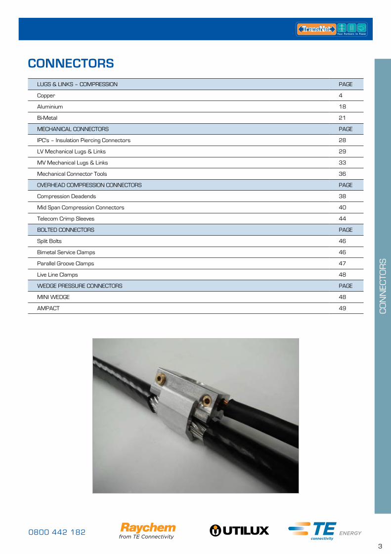
LUGS & LINKS – COMPRESSION PAGE
Copper 4
Aluminium 18
Bi-Metal 21
MECHANICAL CONNECTORS PAGE
IPC's – Insulation Piercing Connectors 28
LV Mechanical Lugs & Links 29
MV Mechanical Lugs & Links 33
Mechanical Connector Tools 36
OVERHEAD COMPRESSION CONNECTORS PAGE
Compression Deadends 38
Mid Span Compression Connectors 40
Telecom Crimp Sleeves 44
BOLTED CONNECTORS PAGE
Split Bolts 46
Bimetal Service Clamps 46
Parallel Groove Clamps 47
Live Line Clamps 48
WEDGE PRESSURE CONNECTORS PAGE
MINI WEDGE 48
AMPACT 49
CONNECTORS
www.transnet.co.nz
4
CO
NN
ECTO
RS
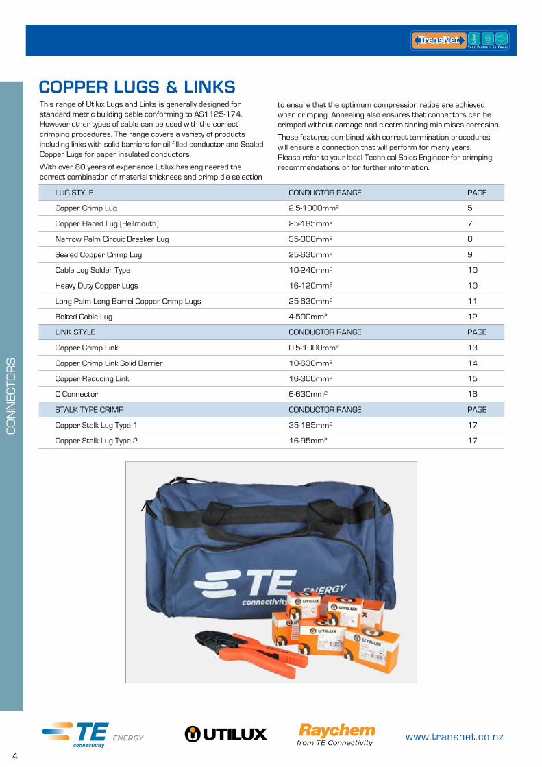
This range of Utilux Lugs and Links is generally designed for standard metric building cable conforming to AS1125-174. However other types of cable can be used with the correct crimping procedures. The range covers a variety of products including links with solid barriers for oil filled conductor and Sealed Copper Lugs for paper insulated conductors.
With over 80 years of experience Utilux has engineered the correct combination of material thickness and crimp die selection
LUG STYLE CONDUCTOR RANGE PAGE
Copper Crimp Lug 2.5-1000mm² 5
Copper Flared Lug (Bellmouth) 25-185mm² 7
Narrow Palm Circuit Breaker Lug 35-300mm² 8
Sealed Copper Crimp Lug 25-630mm² 9
Cable Lug Solder Type 10-240mm² 10
Heavy Duty Copper Lugs 16-120mm² 10
Long Palm Long Barrel Copper Crimp Lugs 25-630mm² 11
Bolted Cable Lug 4-500mm² 12
LINK STYLE CONDUCTOR RANGE PAGE
Copper Crimp Link 0.5-1000mm² 13
Copper Crimp Link Solid Barrier 10-630mm² 14
Copper Reducing Link 16-300mm² 15
C Connector 6-630mm² 16
STALK TYPE CRIMP CONDUCTOR RANGE PAGE
Copper Stalk Lug Type 1 35-185mm² 17
Copper Stalk Lug Type 2 16-95mm² 17
to ensure that the optimum compression ratios are achieved when crimping. Annealing also ensures that connectors can be crimped without damage and electro tinning minimises corrosion.
These features combined with correct termination procedures will ensure a connection that will perform for many years. Please refer to your local Technical Sales Engineer for crimping recommendations or for further information.
COPPER LUGS & LINKS
0800 442 182
5
CO
NN
ECTO
RS
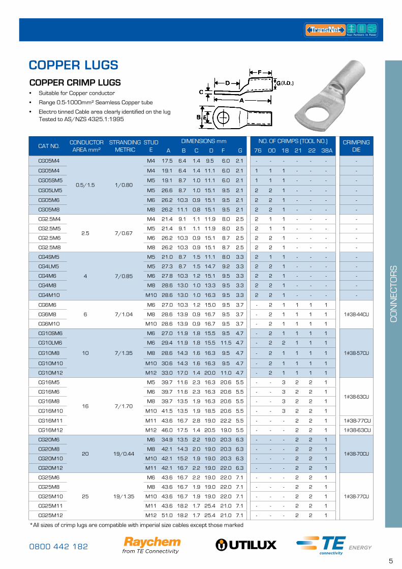
COPPER LUGSCOPPER CRIMP LUGS• Suitable for Copper conductor
• Range 0.5-1000mm² Seamless Copper tube
• Electro tinned Cable area clearly identified on the lug Tested to AS/NZS 4325.1:1995
*All sizes of crimp lugs are compatible with imperial size cables except those marked
CAT NO.CONDUCTOR AREA mm²
STRANDING METRIC
STUDE
DIMENSIONS mm NO. OF CRIMPS (TOOL N0.) CRIMPING DIEA B C D F G 76 00 18 21 22 38A
CG05M4
0.5/1.5 1/0.80
M4 17.5 6.4 1.4 9.5 6.0 2.1 - - - - - - -
CG05M4 M4 19.1 6.4 1.4 11.1 6.0 2.1 1 1 1 - - - -
CG05SM5 M5 19.1 8.7 1.0 11.1 6.0 2.1 1 1 1 - - - -
CG05LM5 M5 26.6 8.7 1.0 15.1 9.5 2.1 2 2 1 - - - -
CG05M6 M6 26.2 10.3 0.9 15.1 9.5 2.1 2 2 1 - - - -
CG05M8 M8 26.2 11.1 0.8 15.1 9.5 2.1 2 2 1 - - - -
CG2.5M4
2.5 7/0.67
M4 21.4 9.1 1.1 11.9 8.0 2.5 2 1 1 - - - -
CG2.5M5 M5 21.4 9.1 1.1 11.9 8.0 2.5 2 1 1 - - - -
CG2.5M6 M6 26.2 10.3 0.9 15.1 8.7 2.5 2 2 1 - - - -
CG2.5M8 M8 26.2 10.3 0.9 15.1 8.7 2.5 2 2 1 - - - -
CG4SM5
4 7/0.85
M5 21.0 8.7 1.5 11.1 8.0 3.3 2 1 1 - - - -
CG4LM5 M5 27.3 8.7 1.5 14.7 9.2 3.3 2 2 1 - - - -
CG4M6 M6 27.8 10.3 1.2 15.1 9.5 3.3 2 2 1 - - - -
CG4M8 M8 28.6 13.0 1.0 13.3 9.5 3.3 2 2 1 - - - -
CG4M10 M10 28.6 13.0 1.0 16.3 9.5 3.3 2 2 1 - - - -
CG6M6
6 7/1.04
M6 27.0 10.3 1.2 15.0 9.5 3.7 - 2 1 1 1 1
1#38-44CUCG6M8 M8 28.6 13.9 0.9 16.7 9.5 3.7 - 2 1 1 1 1
CG6M10 M10 28.6 13.9 0.9 16.7 9.5 3.7 - 2 1 1 1 1
CG10SM6
10 7/1.35
M6 27.0 11.9 1.8 15.5 9.5 4.7 - 2 1 1 1 1
1#38-57CU
CG10LM6 M6 29.4 11.9 1.8 15.5 11.5 4.7 - 2 2 1 1 1
CG10M8 M8 28.6 14.3 1.6 16.3 9.5 4.7 - 2 1 1 1 1
CG10M10 M10 30.6 14.3 1.6 16.3 9.5 4.7 - 2 1 1 1 1
CG10M12 M12 33.0 17.0 1.4 20.0 11.0 4.7 - 2 1 1 1 1
CG16M5
16 7/1.70
M5 39.7 11.6 2.3 16.3 20.6 5.5 - - 3 2 2 1
1#38-63CUCG16M6 M6 39.7 11.6 2.3 16.3 20.6 5.5 - - 3 2 2 1
CG16M8 M8 39.7 13.5 1.9 16.3 20.6 5.5 - - 3 2 2 1
CG16M10 M10 41.5 13.5 1.9 18.5 20.6 5.5 - - 3 2 2 1
CG16M11 M11 43.6 16.7 2.8 19.0 22.2 5.5 - - - 2 2 1 1#38-77CU
CG16M12 M12 46.0 17.5 1.4 20.5 19.0 5.5 - - - 2 2 1 1#38-63CU
CG20M6
20 19/0.44
M6 34.9 13.5 2.2 19.0 20.3 6.3 - - - 2 2 1
1#38-70CUCG20M8 M8 42.1 14.3 2.0 19.0 20.3 6.3 - - - 2 2 1
CG20M10 M10 42.1 15.2 1.9 19.0 20.3 6.3 - - - 2 2 1
CG20M12 M11 42.1 16.7 2.2 19.0 22.0 6.3 - - - 2 2 1
CG25M6
25 19/1.35
M6 43.6 16.7 2.2 19.0 22.0 7.1 - - - 2 2 1
1#38-77CU
CG25M8 M8 43.6 16.7 1.9 19.0 22.0 7.1 - - - 2 2 1
CG25M10 M10 43.6 16.7 1.9 19.0 22.0 7.1 - - - 2 2 1
CG25M11 M11 43.6 18.2 1.7 25.4 21.0 7.1 - - - 2 2 1
CG25M12 M12 51.0 18.2 1.7 25.4 21.0 7.1 - - - 2 2 1
www.transnet.co.nz
6
CO
NN
ECTO
RS
*All sizes of crimp lugs are compatible with imperial size cables except those marked
CAT NO.CONDUCTOR AREA mm²
CONDUCTOR SIZE
STUDE
DIMENSIONS (mm) NO. OF CRIMPS (TOOL) CRIMPING DIEA B C D F G 21 22 38A 40B
CG35M6
35 19/153
M6 43.6 18.2 2.7 19.0 22.2 8.4 2 2 1 -
1#38-92CUCG35M8 M8 43.6 18.2 2.7 19.0 22.2 8.4 2 2 1 -
CG35M10 M10 43.6 18.2 2.7 19.0 22.2 8.4 2 2 1 -
CG35M11 38 7/0.104 M11 51.6 19.0 3.7 27.0 22.2 8.7 2 2 1 - 1#38-104CU
CG35M12 35 19/1.53 M12 51.2 20.0 2.4 24.5 22.0 8.4 2 2 1 - 1#38-92CU
CG50M8
50 19/1.78
M8 51.6 18.2 3.1 27.0 22.2 9.5 2 2 1 -
1#38-104CUCG50M10 M10 51.6 19.0 3.0 27.0 22.2 9.5 2 2 1 -
CG50M12 M12 51.6 20.6 2.8 27.0 22.2 9.5 2 2 1 -
CG70M6
70 19/2.14
M6 54.0 20.6 3.2 27.0 23.0 11.0 - 2 1 -
1#38-115CUCG70M8 M8 54.0 20.6 3.2 27.0 23.0 11.0 - 2 1 -
CG70M10 M10 54.0 20.6 3.2 27.0 23.0 11.0 - 2 1 -
CG70M11 M11 54.0 22.2 4.7 27.0 23.0 11.2 - 2 1 - 1#38-130CU
CG70M12 M12 54.0 20.6 3.2 27.0 23.0 11.0 - 2 1 -1#38-115CU
CG70M16 M16 54.2 27.5 2.4 27.0 22.0 11.0 - 2 1 -
G70M20 M20 76.0 28.6 3.5 45.0 25.4 11.0 - - 1 1 1#38-142CU
CG95M6
95 37/1.78
M6 57.2 25.4 4.0 27.0 27.0 13.4 - 2 1 1
1#38-142CU 1#40-142CU
G95M8 M8 57.2 25.4 4.0 27.0 27.0 13.4 - 2 1 1
CG95M10 M10 57.2 25.4 4.0 27.0 27.0 13.4 - 2 1 1
CG95M12 M12 57.2 25.4 4.0 27.0 27.0 13.4 - 2 1 1
CG95M16 M16 75.5 27.0 3.7 45.0 25.4 13.4 - 2 1 1
CG95M20 M20 75.5 28.6 3.5 45.0 25.4 13.4 - 2 1 1
CG120M10
120 37/2.03
M10 68.3 30.0 4.8 31.8 31.0 15.5 - 2 2 1
1#38-165CU 1#40-165CU
CG120M12 M12 68.3 30.0 4.8 31.8 31.0 15.5 - 2 2 1
CG120M16 M16 68.3 30.0 4.8 31.8 31.0 15.5 - 2 2 1
CG120M20 M20 68.3 30.0 4.8 31.8 31.0 15.5 - 2 2 1
CG150M10*
150 37/2.25
M10 75.0 33.5 5.4 41.3 27.0 16.3 - - 2 1
1#38-183CU 1#40-185CU
CG150M12* M12 75.0 33.5 5.4 41.3 27.0 16.3 - - 2 1
CG150M16* M16 75.0 33.5 5.4 41.3 27.0 16.3 - - 2 1
CG150M20* M20 75.0 33.5 5.4 41.3 27.0 16.3 - - 2 1
CG185M10
185 37/2.52
M10 79.0 36.5 5.2 41.3 31.0 18.4 - - 2 1
1#38-200CU 1#40-200CU
CG185M12 M12 79.0 36.5 5.2 41.3 31.0 18.4 - - 2 1
CG185M16 M16 79.0 36.5 5.2 41.3 31.0 18.4 - - 2 1
CG185M20 M20 79.0 36.5 5.2 41.3 31.0 18.4 - - 2 1
CG240MB*
240 61/2.25
MB 127.0 41.6 7.1 54.0 47.6 21.2 - - 3 1
1#38-231CU 1#40-231CU
CG240M10* M10 127.0 41.6 7.1 54.0 47.6 21.2 - - 3 1
CG240M12* M12 127.0 41.6 7.1 54.0 47.6 21.2 - - 3 1
CG240M16* M16 127.0 41.6 7.1 54.0 47.6 21.2 - - 3 1
CG240M20* M20 127.0 41.6 7.1 54.0 47.6 21.2 - - 3 1
CG300MB
300 61/2.52
MB 127.0 46.0 7.9 54.0 47.6 23.8 - - 3 11#38-260CU 1#40-260CUCG300M16 M16 127.0 46.0 7.9 54.0 47.6 23.8 - - 3 1
CG300M20 M20 127.0 46.0 7.9 54.0 47.6 23.8 - - 3 1
CG400MB
400 61/2.85
MB 123.0 49.6 7.9 54.0 41.3 26.9 - - - 1
1#40-281CUCG400M16 M16 123.0 49.6 7.9 54.0 41.3 26.9 - - - 1
CG400M20 M20 123.0 49.6 7.9 54.0 41.3 26.9 - - - 1
CG500MB
500 61/3.20
MB 142.5 54.8 8.2 54.0 55.5 30.0 - - - 2
1#40-310CUG500M16 M16 142.5 54.8 8.2 54.0 55.5 30.0 - - - 2
CG500M20 M20 142.5 54.8 8.2 54.0 55.5 30.0 - - - 2
CG630MB* 630 127/2.52 MB 146.0 63.5 11.5 54.0 58.0 33.5 - - - 2 1#40-370CU
CG800MB 800 127/2.85 MB 275.0 75.0 14.0 127.0 105.0 39.3 - - - 3 1#40-432CU
CG1000MB 1000 127/3.20 MB 295.0 85.0 16.0 125.0 110.0 44.0 - - - 3 1#40-480CU
0800 442 182
7
CO
NN
ECTO
RS
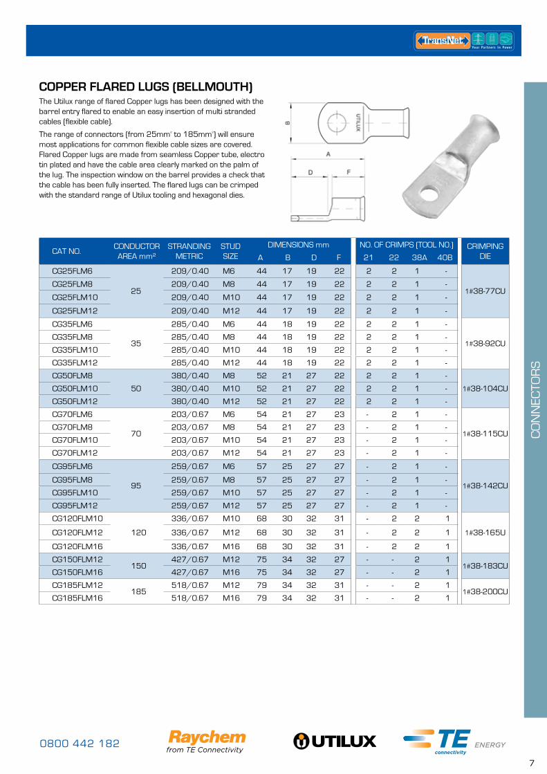
COPPER FLARED LUGS (BELLMOUTH)The Utilux range of flared Copper lugs has been designed with the barrel entry flared to enable an easy insertion of multi stranded cables (flexible cable).
The range of connectors (from 25mm² to 185mm²) will ensure most applications for common flexible cable sizes are covered. Flared Copper lugs are made from seamless Copper tube, electro tin plated and have the cable area clearly marked on the palm of the lug. The inspection window on the barrel provides a check that the cable has been fully inserted. The flared lugs can be crimped with the standard range of Utilux tooling and hexagonal dies.
CAT NO.CONDUCTOR AREA mm²
STRANDING METRIC
STUDSIZE
DIMENSIONS mm NO. OF CRIMPS (TOOL N0.) CRIMPING DIEA B D F 21 22 38A 40B
CG25FLM6
25
209/0.40 M6 44 17 19 22 2 2 1 -
1#38-77CUCG25FLM8 209/0.40 M8 44 17 19 22 2 2 1 -
CG25FLM10 209/0.40 M10 44 17 19 22 2 2 1 -
CG25FLM12 209/0.40 M12 44 17 19 22 2 2 1 -
CG35FLM6
35
285/0.40 M6 44 18 19 22 2 2 1 -
1#38-92CUCG35FLM8 285/0.40 M8 44 18 19 22 2 2 1 -
CG35FLM10 285/0.40 M10 44 18 19 22 2 2 1 -
CG35FLM12 285/0.40 M12 44 18 19 22 2 2 1 -
CG50FLM8
50
380/0.40 M8 52 21 27 22 2 2 1 -
1#38-104CUCG50FLM10 380/0.40 M10 52 21 27 22 2 2 1 -
CG50FLM12 380/0.40 M12 52 21 27 22 2 2 1 -
CG70FLM6
70
203/0.67 M6 54 21 27 23 - 2 1 -
1#38-115CUCG70FLM8 203/0.67 M8 54 21 27 23 - 2 1 -
CG70FLM10 203/0.67 M10 54 21 27 23 - 2 1 -
CG70FLM12 203/0.67 M12 54 21 27 23 - 2 1 -
CG95FLM6
95
259/0.67 M6 57 25 27 27 - 2 1 -
1#38-142CUCG95FLM8 259/0.67 M8 57 25 27 27 - 2 1 -
CG95FLM10 259/0.67 M10 57 25 27 27 - 2 1 -
CG95FLM12 259/0.67 M12 57 25 27 27 - 2 1 -
CG120FLM10
120
336/0.67 M10 68 30 32 31 - 2 2 1
1#38-165UCG120FLM12 336/0.67 M12 68 30 32 31 - 2 2 1
CG120FLM16 336/0.67 M16 68 30 32 31 - 2 2 1
CG150FLM12150
427/0.67 M12 75 34 32 27 - - 2 11#38-183CU
CG150FLM16 427/0.67 M16 75 34 32 27 - - 2 1
CG185FLM12185
518/0.67 M12 79 34 32 31 - - 2 11#38-200CU
CG185FLM16 518/0.67 M16 79 34 32 31 - - 2 1
www.transnet.co.nz
8
CO
NN
ECTO
RS
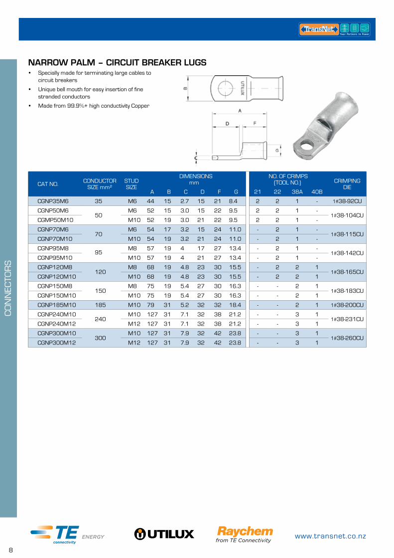
• Specially made for terminating large cables to circuit breakers
• Unique bell mouth for easy insertion of fine stranded conductors
• Made from 99.9%+ high conductivity Copper
CAT NO. CONDUCTOR SIZE mm²
STUDSIZE
DIMENSIONS mm
NO. OF CRIMPS (TOOL NO.) CRIMPING
DIEA B C D F G 21 22 38A 40B
CGNP35M6 35 M6 44 15 2.7 15 21 8.4 2 2 1 - 1#38-92CU
CGNP50M650
M6 52 15 3.0 15 22 9.5 2 2 1 -1#38-104CU
CGMP50M10 M10 52 19 3.0 21 22 9.5 2 2 1 -
CGNP70M670
M6 54 17 3.2 15 24 11.0 - 2 1 -1#38-115CU
CGNP70M10 M10 54 19 3.2 21 24 11.0 - 2 1 -
CGNP95M895
M8 57 19 4 17 27 13.4 - 2 1 -1#38-142CU
CGNP95M10 M10 57 19 4 21 27 13.4 - 2 1 -
CGNP120M8120
M8 68 19 4.8 23 30 15.5 - 2 2 11#38-165CU
CGNP120M10 M10 68 19 4.8 23 30 15.5 - 2 2 1
CGNP150M8150
M8 75 19 5.4 27 30 16.3 - - 2 11#38-183CU
CGNP150M10 M10 75 19 5.4 27 30 16.3 - - 2 1
CGNP185M10 185 M10 79 31 5.2 32 32 18.4 - - 2 1 1#38-200CU
CGNP240M10240
M10 127 31 7.1 32 38 21.2 - - 3 11#38-231CU
CGNP240M12 M12 127 31 7.1 32 38 21.2 - - 3 1
CGNP300M10300
M10 127 31 7.9 32 42 23.8 - - 3 11#38-260CU
CGNP300M12 M12 127 31 7.9 32 42 23.8 - - 3 1
NARROW PALM – CIRCUIT BREAKER LUGS
0800 442 182
9
CO
NN
ECTO
RS
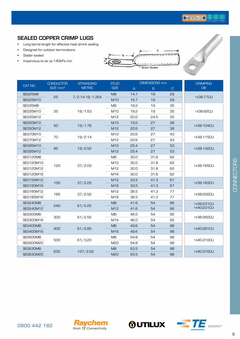
SEALED COPPER CRIMP LUGS• Long barrel length for effective heat shrink sealing
• Designed for outdoor terminations
• Solder sealed
• Impervious to air at 140kPa min
CAT NO.CONDUCTOR
SIZE mm²STRANDING
METRICSTUDSIZE
DIMENSIONS mm CRIMPING DIEA B C
SEG25M825 7/2.14-19/1.354
M8 14.7 19 291#38-77CU
SEG25M10 M10 16.7 19 29
SEG35M8
35 19/1.53
M8 18.2 19 35
1#38-92CUSEG35M10 M10 18.2 19 35
SEG35M12 M12 20.0 24.5 35
SEG50M1050 19/1.78
M10 19.0 27 381#38-104CU
SEG50M12 M12 20.6 27 38
SEG70M1070 19/2.14
M10 20.6 27 431#38-115CU
SEG70M12 M12 20.6 27 43
SEG95M1095 19/2.52
M10 25.4 27 531#38-142CU
SEG95M12 M12 25.4 27 53
SEG120MB
120 37/2.03
MB 30.0 31.8 62
1#38-165CUSEG120M10 M10 30.0 31.8 62
SEG120M12 M12 30.0 31.8 62
SEG120M16 M16 30.0 31.8 62
SEG150M12150 37/2.25
M12 33.5 41.3 671#38-183CU
SEG150M16 M16 33.5 41.3 67
SEG185M12185 37/2.52
M12 36.5 41.3 771#38-200CU
SEG185M16 M16 36.5 41.3 77
SEG240MB240 61/2.25
MB 41.6 54 86 1#38-231CU 1#40-231CUSEG240M12 M12 41.6 54 86
SEG300MB300 61/2.52
MB 46.0 54 951#38-260CU
SEG300M16 M16 46.0 54 95
SEG400MB400 61/2.85
MB 49.6 54 981#40-281CU
SEG400M16 M16 49.6 54 98
SEG500MB500 61/3.20
MB 54.8 54 981#40-310CU
SEG500M20 M20 54.8 54 98
SEG630MB630 127/2.52
MB 63.5 54 981#40-370CU
SEG630M20 M20 63.5 54 98
www.transnet.co.nz
10
CO
NN
ECTO
RS
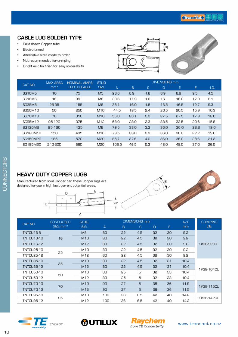
CABLE LUG SOLDER TYPE• Solid drawn Copper tube
• Electro tinned
• Alternative sizes made to order
• Not recommended for crimping
• Bright acid tin finish for easy solderability
CAT NO.MAX AREA
mm²NOMINAL AMPS FOR CU CABLE
STUDSIZE
DIMENSIONS mm
A B C D E F I.D.
SG10M5 10 75 M5 28.6 8.9 1.8 8.9 8.9 9.5 4.5
SG16M6 16 99 M6 38.6 11.9 1.6 16 16.0 17.0 6.1
SG35M8 25-35 155 M8 38.1 16.0 1.8 16.5 16.5 12.7 9.3
SG50M10 50 250 M10 44.5 18.5 2.4 20.5 20.5 15.9 10.3
SG70M10 70 310 M10 56.0 23.1 3.3 27.5 27.5 17.9 12.6
SG95M12 95-120 375 M12 68.0 28.0 3.3 33.5 33.5 20.6 15.8
SG120MB 95-120 435 MB 79.5 33.0 3.3 36.0 36.0 22.2 19.0
SG120M16 150 435 M16 79.5 33.0 3.3 36.0 36.0 22.2 19.0
SG150M20 185 570 M20 85.7 37.6 4.0 36.0 36.0 28.6 21.3
SG185M20 240-300 680 M20 106.5 46.5 5.3 48.0 48.0 37.0 26.5
HEAVY DUTY COPPER LUGS
CAT NO.CONDUCTOR
SIZE mm²STUDSIZE
DIMENSIONS mm A/Fmm
CRIMPING DIEA B C D E
TNTCU16-8
16
M8 80 22 4.5 32 30 9.2
1#38-92CU
TNTCU16-10 M10 80 22 4.5 32 30 9.2
TNTCU16-12 M12 80 22 4.5 32 30 9.2
TNTCU25-1025
M10 80 22 4.5 32 30 9.2
TNTCU25-12 M12 80 22 4.5 32 30 9.2
TNTCU35-1035
M10 80 22 4.5 32 31 10.4
1#38-104CUTNTCU35-12 M12 80 22 4.5 32 31 10.4
TNTCU50-1050
M10 80 25 5 32 33 10.4
TNTCU50-12 M12 80 25 5 32 33 10.4
TNTCU70-1070
M10 90 27 6 38 36 11.51#38-115CU
TNTCU70-12 M12 90 27 6 38 36 11.5
TNTCU95-1095
M10 100 36 6.5 42 40 14.21#38-142CU
TNTCU95-12 M12 100 36 6.5 42 40 14.2
Manufactured from solid Copper bar, these Copper lugs are designed for use in high fault current potential areas.
D E
C
A
B
0800 442 182
11
CO
NN
ECTO
RS
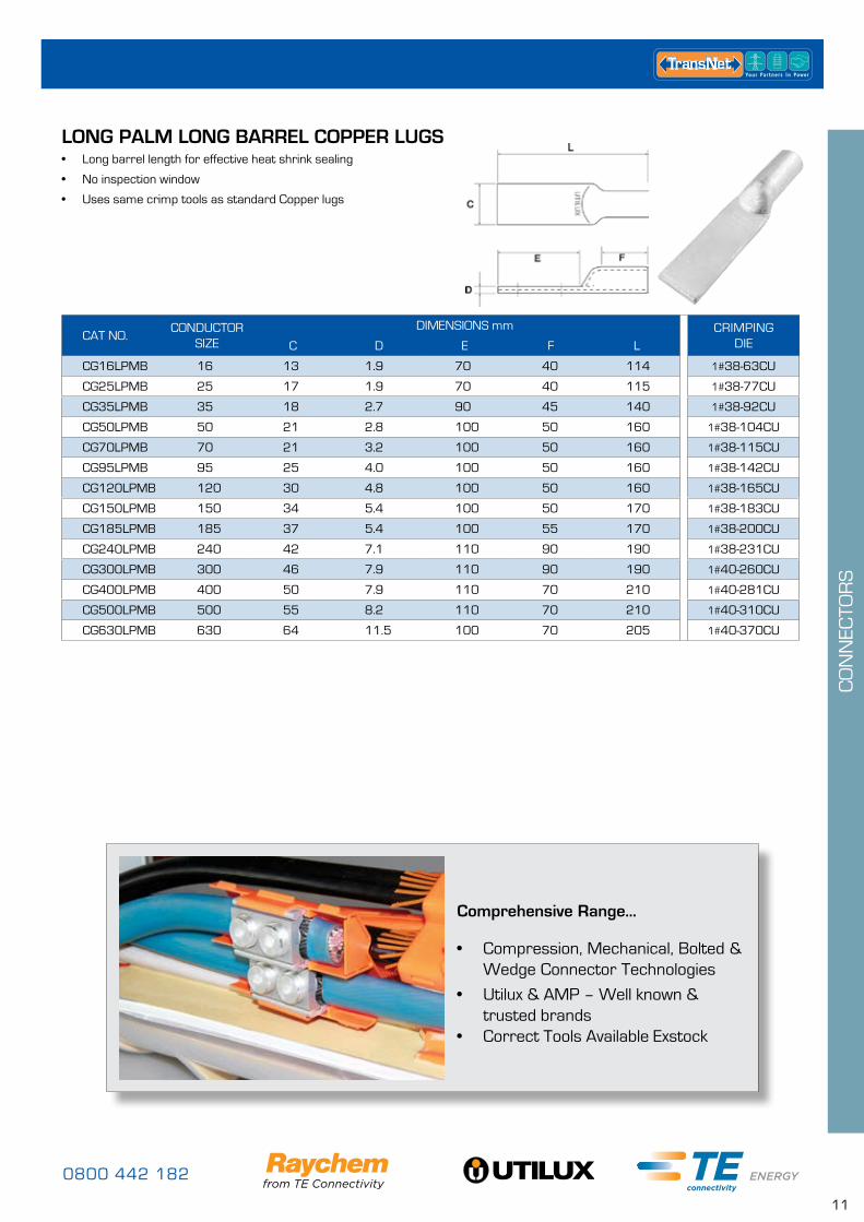
LONG PALM LONG BARREL COPPER LUGS• Long barrel length for effective heat shrink sealing
• No inspection window
• Uses same crimp tools as standard Copper lugs
CAT NO.CONDUCTOR
SIZEDIMENSIONS mm CRIMPING
DIEC D E F L
CG16LPMB 16 13 1.9 70 40 114 1#38-63CU
CG25LPMB 25 17 1.9 70 40 115 1#38-77CU
CG35LPMB 35 18 2.7 90 45 140 1#38-92CU
CG50LPMB 50 21 2.8 100 50 160 1#38-104CU
CG70LPMB 70 21 3.2 100 50 160 1#38-115CU
CG95LPMB 95 25 4.0 100 50 160 1#38-142CU
CG120LPMB 120 30 4.8 100 50 160 1#38-165CU
CG150LPMB 150 34 5.4 100 50 170 1#38-183CU
CG185LPMB 185 37 5.4 100 55 170 1#38-200CU
CG240LPMB 240 42 7.1 110 90 190 1#38-231CU
CG300LPMB 300 46 7.9 110 90 190 1#40-260CU
CG400LPMB 400 50 7.9 110 70 210 1#40-281CU
CG500LPMB 500 55 8.2 110 70 210 1#40-310CU
CG630LPMB 630 64 11.5 100 70 205 1#40-370CU
Comprehensive Range...
• Compression, Mechanical, Bolted & Wedge Connector Technologies
• Utilux & AMP – Well known & trusted brands
• Correct Tools Available Exstock
www.transnet.co.nz
12
CO
NN
ECTO
RS
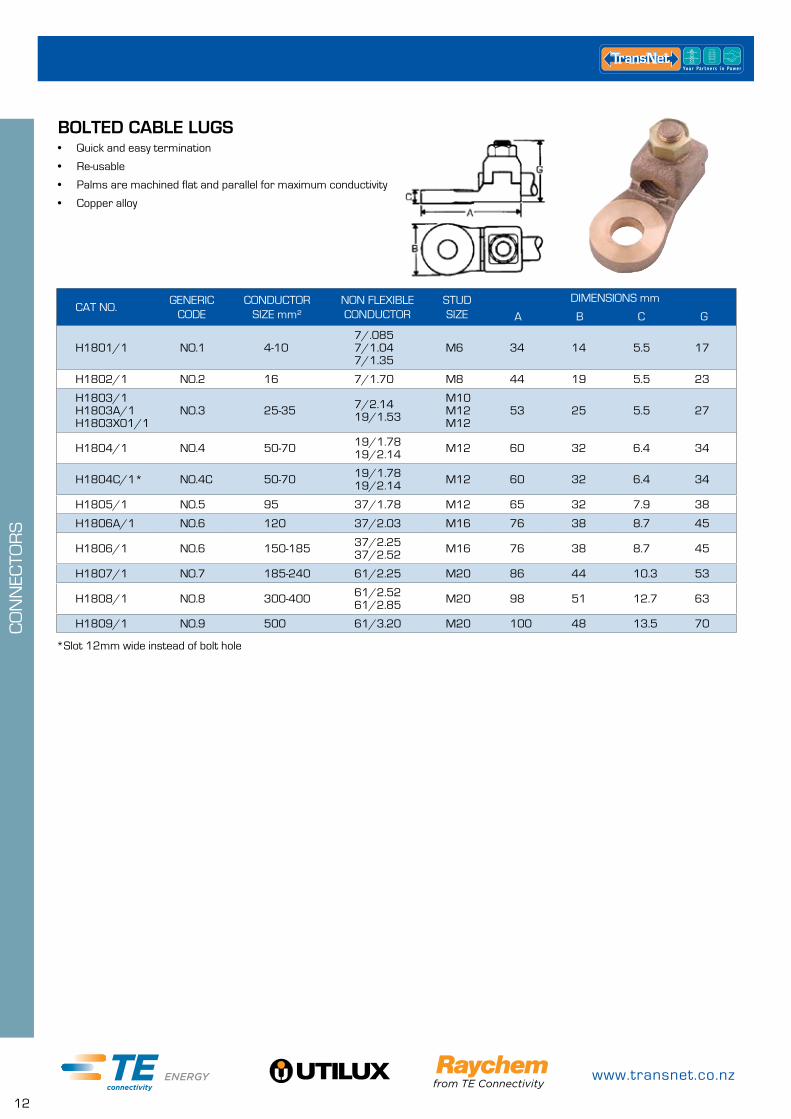
BOLTED CABLE LUGS• Quick and easy termination
• Re-usable
• Palms are machined flat and parallel for maximum conductivity
• Copper alloy
*Slot 12mm wide instead of bolt hole
CAT NO.GENERIC
CODECONDUCTOR
SIZE mm²NON FLEXIBLE CONDUCTOR
STUD SIZE
DIMENSIONS mm
A B C G
H1801/1 NO.1 4-107/.085 7/1.04 7/1.35
M6 34 14 5.5 17
H1802/1 NO.2 16 7/1.70 M8 44 19 5.5 23
H1803/1 H1803A/1 H1803X01/1
NO.3 25-35 7/2.14 19/1.53
M10 M12 M12
53 25 5.5 27
H1804/1 NO.4 50-70 19/1.78 19/2.14 M12 60 32 6.4 34
H1804C/1* NO.4C 50-70 19/1.78 19/2.14 M12 60 32 6.4 34
H1805/1 NO.5 95 37/1.78 M12 65 32 7.9 38
H1806A/1 NO.6 120 37/2.03 M16 76 38 8.7 45
H1806/1 NO.6 150-185 37/2.25 37/2.52 M16 76 38 8.7 45
H1807/1 NO.7 185-240 61/2.25 M20 86 44 10.3 53
H1808/1 NO.8 300-400 61/2.52 61/2.85 M20 98 51 12.7 63
H1809/1 NO.9 500 61/3.20 M20 100 48 13.5 70
0800 442 182
13
CO
NN
ECTO
RS
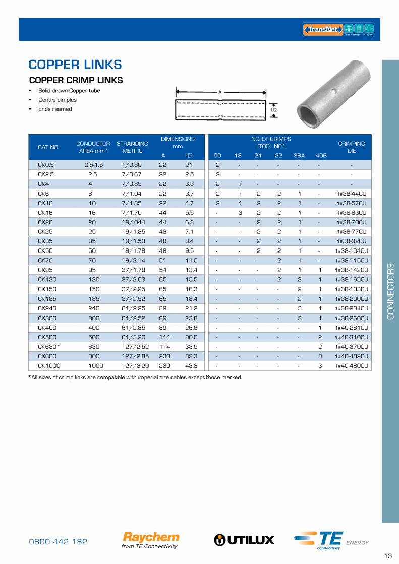
COPPER CRIMP LINKS• Solid drawn Copper tube
• Centre dimples
• Ends reamed
*All sizes of crimp links are compatible with imperial size cables except those marked
CAT NO.CONDUCTOR AREA mm²
STRANDING METRIC
DIMENSIONS mm
NO. OF CRIMPS (TOOL N0.) CRIMPING
DIEA I.D. 00 18 21 22 38A 40B
CK0.5 0.5-1.5 1/0.80 22 21 2 - - - - - -
CK2.5 2.5 7/0.67 22 2.5 2 - - - - - -
CK4 4 7/0.85 22 3.3 2 1 - - - - -
CK6 6 7/1.04 22 3.7 2 1 2 2 1 - 1#38-44CU
CK10 10 7/1.35 22 4.7 2 1 2 2 1 - 1#38-57CU
CK16 16 7/1.70 44 5.5 - 3 2 2 1 - 1#38-63CU
CK20 20 19/.044 44 6.3 - - 2 2 1 - 1#38-70CU
CK25 25 19/1.35 48 7.1 - - 2 2 1 - 1#38-77CU
CK35 35 19/1.53 48 8.4 - - 2 2 1 - 1#38-92CU
CK50 50 19/1.78 48 9.5 - - 2 2 1 - 1#38-104CU
CK70 70 19/2.14 51 11.0 - - - 2 1 - 1#38-115CU
CK95 95 37/1.78 54 13.4 - - - 2 1 1 1#38-142CU
CK120 120 37/2.03 65 15.5 - - - 2 2 1 1#38-165CU
CK150 150 37/2.25 65 16.3 - - - - 2 1 1#38-183CU
CK185 185 37/2.52 65 18.4 - - - - 2 1 1#38-200CU
CK240 240 61/2.25 89 21.2 - - - - 3 1 1#38-231CU
CK300 300 61/2.52 89 23.8 - - - - 3 1 1#38-260CU
CK400 400 61/2.85 89 26.8 - - - - - 1 1#40-281CU
CK500 500 61/3.20 114 30.0 - - - - - 2 1#40-310CU
CK630* 630 127/2.52 114 33.5 - - - - - 2 1#40-370CU
CK800 800 127/2.85 230 39.3 - - - - - 3 1#40-432CU
CK1000 1000 127/3.20 230 43.8 - - - - - 3 1#40-480CU
COPPER LINKS
www.transnet.co.nz
14
CO
NN
ECTO
RS
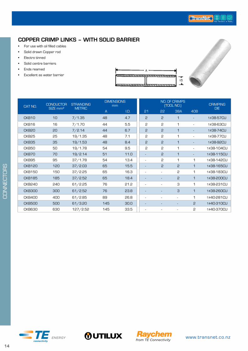
COPPER CRIMP LINKS – WITH SOLID BARRIER• For use with oil filled cables
• Solid drawn Copper rod
• Electro tinned
• Solid centre barriers
• Ends reamed
• Excellent as water barrier
CAT NO. CONDUCTOR SIZE mm²
STRANDING METRIC
DIMENSIONS mm
NO. OF CRIMPS (TOOL NO.) CRIMPING
DIEA I.D. 21 22 38A 40B
CKB10 10 7/1.35 48 4.7 2 2 1 - 1#38-57CU
CKB16 16 7/1.70 44 5.5 2 2 1 - 1#38-63CU
CKB20 20 7/2.14 44 6.7 2 2 1 - 1#38-74CU
CKB25 25 19/1.35 48 7.1 2 2 1 - 1#38-77CU
CKB35 35 19/1.53 48 8.4 2 2 1 - 1#38-92CU
CKB50 50 19/1.78 54 9.5 2 2 1 - 1#38-104CU
CKB70 70 19/2.14 51 11.0 - 2 1 - 1#38-115CU
CKB95 95 37/1.78 54 13.4 - 2 1 1 1#38-142CU
CKB120 120 37/2.03 65 15.5 - 2 2 1 1#38-165CU
CKB150 150 37/2.25 65 16.3 - - 2 1 1#38-183CU
CKB185 185 37/2.52 65 18.4 - - 2 1 1#38-200CU
CKB240 240 61/2.25 76 21.2 - - 3 1 1#38-231CU
CKB300 300 61/2.52 76 23.8 - - 3 1 1#38-260CU
CKB400 400 61/2.85 89 26.8 - - - 1 1#40-281CU
CKB500 500 61/3.20 145 30.0 - - - 2 1#40-310CU
CKB630 630 127/2.52 145 33.5 - - - 2 1#40-370CU
0800 442 182
15
CO
NN
ECTO
RS
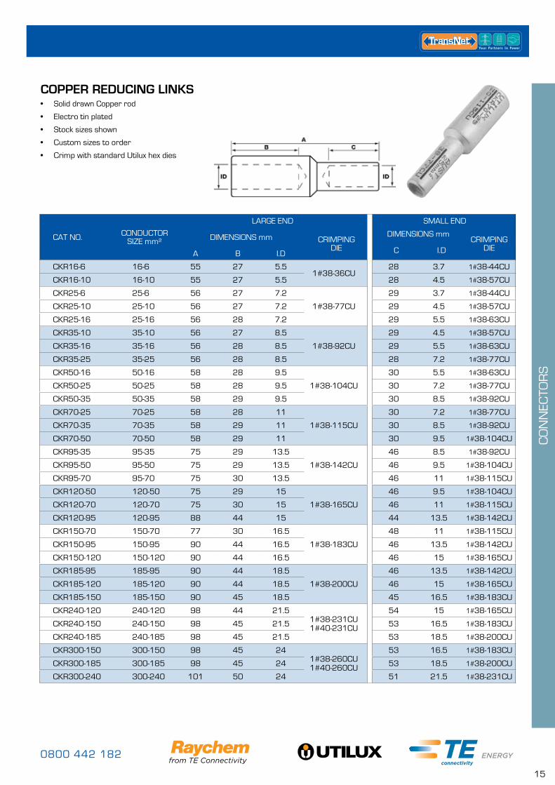
COPPER REDUCING LINKS• Solid drawn Copper rod
• Electro tin plated
• Stock sizes shown
• Custom sizes to order
• Crimp with standard Utilux hex dies
CAT NO. CONDUCTOR SIZE mm²
LARGE END SMALL END
DIMENSIONS mm CRIMPING DIE
DIMENSIONS mmCRIMPING
DIEC I.DA B I.D
CKR16-6 16-6 55 27 5.51#38-36CU
28 3.7 1#38-44CU
CKR16-10 16-10 55 27 5.5 28 4.5 1#38-57CU
CKR25-6 25-6 56 27 7.2
1#38-77CU
29 3.7 1#38-44CU
CKR25-10 25-10 56 27 7.2 29 4.5 1#38-57CU
CKR25-16 25-16 56 28 7.2 29 5.5 1#38-63CU
CKR35-10 35-10 56 27 8.5
1#38-92CU
29 4.5 1#38-57CU
CKR35-16 35-16 56 28 8.5 29 5.5 1#38-63CU
CKR35-25 35-25 56 28 8.5 28 7.2 1#38-77CU
CKR50-16 50-16 58 28 9.5
1#38-104CU
30 5.5 1#38-63CU
CKR50-25 50-25 58 28 9.5 30 7.2 1#38-77CU
CKR50-35 50-35 58 29 9.5 30 8.5 1#38-92CU
CKR70-25 70-25 58 28 11
1#38-115CU
30 7.2 1#38-77CU
CKR70-35 70-35 58 29 11 30 8.5 1#38-92CU
CKR70-50 70-50 58 29 11 30 9.5 1#38-104CU
CKR95-35 95-35 75 29 13.5
1#38-142CU
46 8.5 1#38-92CU
CKR95-50 95-50 75 29 13.5 46 9.5 1#38-104CU
CKR95-70 95-70 75 30 13.5 46 11 1#38-115CU
CKR120-50 120-50 75 29 15
1#38-165CU
46 9.5 1#38-104CU
CKR120-70 120-70 75 30 15 46 11 1#38-115CU
CKR120-95 120-95 88 44 15 44 13.5 1#38-142CU
CKR150-70 150-70 77 30 16.5
1#38-183CU
48 11 1#38-115CU
CKR150-95 150-95 90 44 16.5 46 13.5 1#38-142CU
CKR150-120 150-120 90 44 16.5 46 15 1#38-165CU
CKR185-95 185-95 90 44 18.5
1#38-200CU
46 13.5 1#38-142CU
CKR185-120 185-120 90 44 18.5 46 15 1#38-165CU
CKR185-150 185-150 90 45 18.5 45 16.5 1#38-183CU
CKR240-120 240-120 98 44 21.51#38-231CU 1#40-231CU
54 15 1#38-165CU
CKR240-150 240-150 98 45 21.5 53 16.5 1#38-183CU
CKR240-185 240-185 98 45 21.5 53 18.5 1#38-200CU
CKR300-150 300-150 98 45 241#38-260CU 1#40-260CU
53 16.5 1#38-183CU
CKR300-185 300-185 98 45 24 53 18.5 1#38-200CU
CKR300-240 300-240 101 50 24 51 21.5 1#38-231CU
www.transnet.co.nz
16
CO
NN
ECTO
RS
L
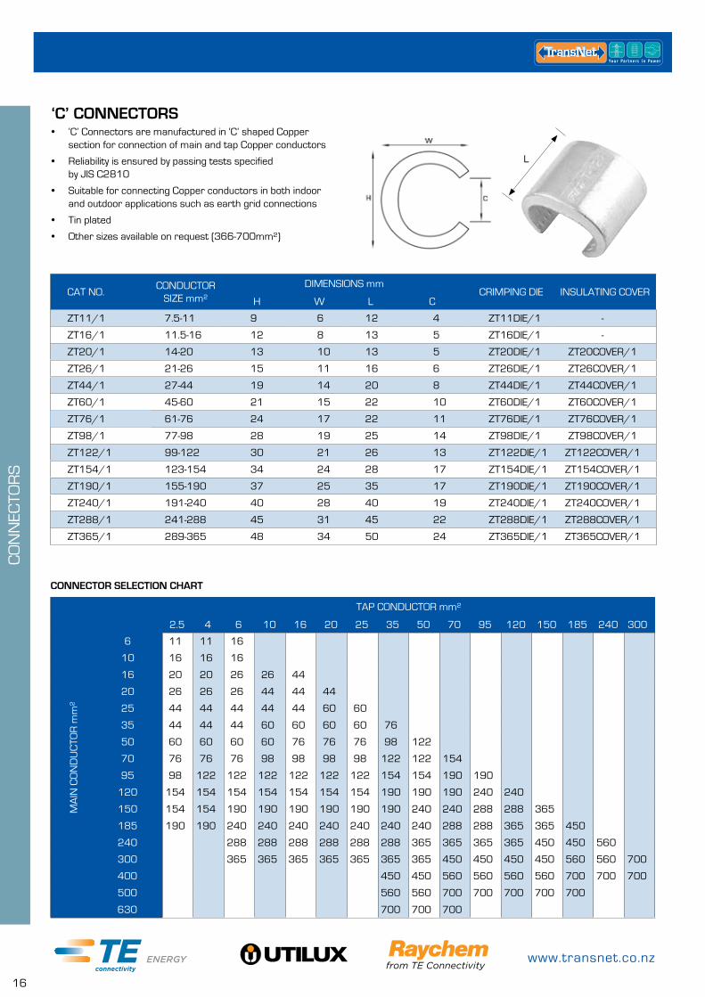
‘C’ CONNECTORS• ‘C’ Connectors are manufactured in ‘C’ shaped Copper
section for connection of main and tap Copper conductors
• Reliability is ensured by passing tests specified by JIS C2810
• Suitable for connecting Copper conductors in both indoor and outdoor applications such as earth grid connections
• Tin plated
• Other sizes available on request (366-700mm²)
L
CAT NO.CONDUCTOR
SIZE mm²DIMENSIONS mm
CRIMPING DIE INSULATING COVERH W L C
ZT11/1 7.5-11 9 6 12 4 ZT11DIE/1 -
ZT16/1 11.5-16 12 8 13 5 ZT16DIE/1 -
ZT20/1 14-20 13 10 13 5 ZT20DIE/1 ZT20COVER/1
ZT26/1 21-26 15 11 16 6 ZT26DIE/1 ZT26COVER/1
ZT44/1 27-44 19 14 20 8 ZT44DIE/1 ZT44COVER/1
ZT60/1 45-60 21 15 22 10 ZT60DIE/1 ZT60COVER/1
ZT76/1 61-76 24 17 22 11 ZT76DIE/1 ZT76COVER/1
ZT98/1 77-98 28 19 25 14 ZT98DIE/1 ZT98COVER/1
ZT122/1 99-122 30 21 26 13 ZT122DIE/1 ZT122COVER/1
ZT154/1 123-154 34 24 28 17 ZT154DIE/1 ZT154COVER/1
ZT190/1 155-190 37 25 35 17 ZT190DIE/1 ZT190COVER/1
ZT240/1 191-240 40 28 40 19 ZT240DIE/1 ZT240COVER/1
ZT288/1 241-288 45 31 45 22 ZT288DIE/1 ZT288COVER/1
ZT365/1 289-365 48 34 50 24 ZT365DIE/1 ZT365COVER/1
CONNECTOR SELECTION CHART
MA
IN C
ON
DU
CTO
R m
m²
TAP CONDUCTOR mm²
2.5 4 6 10 16 20 25 35 50 70 95 120 150 185 240 300
6 11 11 16
10 16 16 16
16 20 20 26 26 44
20 26 26 26 44 44 44
25 44 44 44 44 44 60 60
35 44 44 44 60 60 60 60 76
50 60 60 60 60 76 76 76 98 122
70 76 76 76 98 98 98 98 122 122 154
95 98 122 122 122 122 122 122 154 154 190 190
120 154 154 154 154 154 154 154 190 190 190 240 240
150 154 154 190 190 190 190 190 190 240 240 288 288 365
185 190 190 240 240 240 240 240 240 240 288 288 365 365 450
240 288 288 288 288 288 288 365 365 365 365 450 450 560
300 365 365 365 365 365 365 365 450 450 450 450 560 560 700
400 450 450 560 560 560 560 700 700 700
500 560 560 700 700 700 700 700
630 700 700 700
0800 442 182
17
CO
NN
ECTO
RS
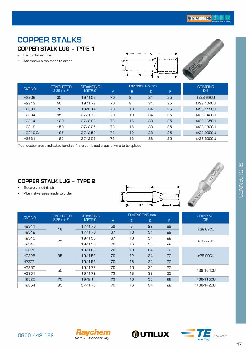
COPPER STALK LUG – TYPE 2• Electro tinned finish
• Alternative sizes made to order
COPPER STALK LUG – TYPE 1• Electro tinned finish
• Alternative sizes made to order
*Conductor areas indicated for style 1 are combined areas of wire to be spliced
CAT NO. CONDUCTOR SIZE mm²
STRANDING METRIC
DIMENSIONS mm CRIMPING DIEA B D F
H2309 35 19/1.53 70 8 34 25 1#38-92CU
H2313 50 19/1.78 70 8 34 25 1#38-104CU
H2331 70 19/2.14 70 10 34 25 1#38-115CU
H2334 95 37/1.78 70 10 34 25 1#38-142CU
H2314 120 37/2.03 73 16 38 25 1#38-165CU
H2318 150 37/2.25 73 16 38 25 1#38-183CU
H2319 Q 185 37/2.52 73 12 38 25 1#38-200CU
H2321 185 37/2.52 73 16 38 25 1#38-200CU
CAT NO. CONDUCTOR SIZE mm²
STRANDING METRIC
DIMENSIONS mm CRIMPING DIEA B D F
H234116
17/1.70 52 8 22 221#38-63CU
H2342 17/1.70 67 10 34 22
H234525
19/1.35 67 10 34 221#38-77CU
H2346 19/1.35 70 16 38 22
H2325
35
19/1.53 70 10 24 22
1#38-90CUH2326 19/1.53 70 12 34 22
H2327 19/1.53 70 16 34 22
H235050
19/1.78 70 10 34 221#38-104CU
H2351 19/1.78 73 16 38 22
H2328 70 19/2.14 73 16 38 22 1#38-115CU
H2354 95 37/1.78 70 16 34 22 1#38-142CU
COPPER STALKS
www.transnet.co.nz
18
CO
NN
ECTO
RS
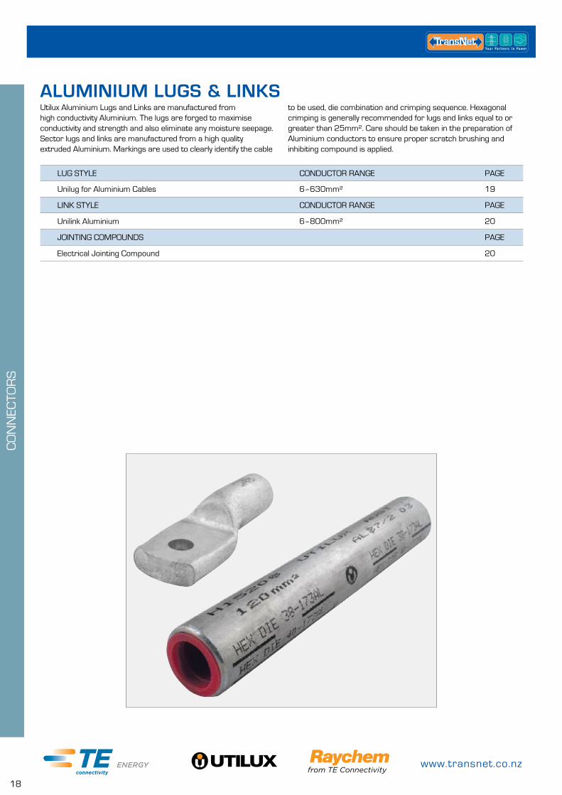
ALUMINIUM LUGS & LINKSUtilux Aluminium Lugs and Links are manufactured from high conductivity Aluminium. The lugs are forged to maximise conductivity and strength and also eliminate any moisture seepage. Sector lugs and links are manufactured from a high quality extruded Aluminium. Markings are used to clearly identify the cable
to be used, die combination and crimping sequence. Hexagonal crimping is generally recommended for lugs and links equal to or greater than 25mm². Care should be taken in the preparation of Aluminium conductors to ensure proper scratch brushing and inhibiting compound is applied.
LUG STYLE CONDUCTOR RANGE PAGE
Unilug for Aluminium Cables 6–630mm² 19
LINK STYLE CONDUCTOR RANGE PAGE
Unilink Aluminium 6–800mm² 20
JOINTING COMPOUNDS PAGE
Electrical Jointing Compound 20
0800 442 182
19
CO
NN
ECTO
RS
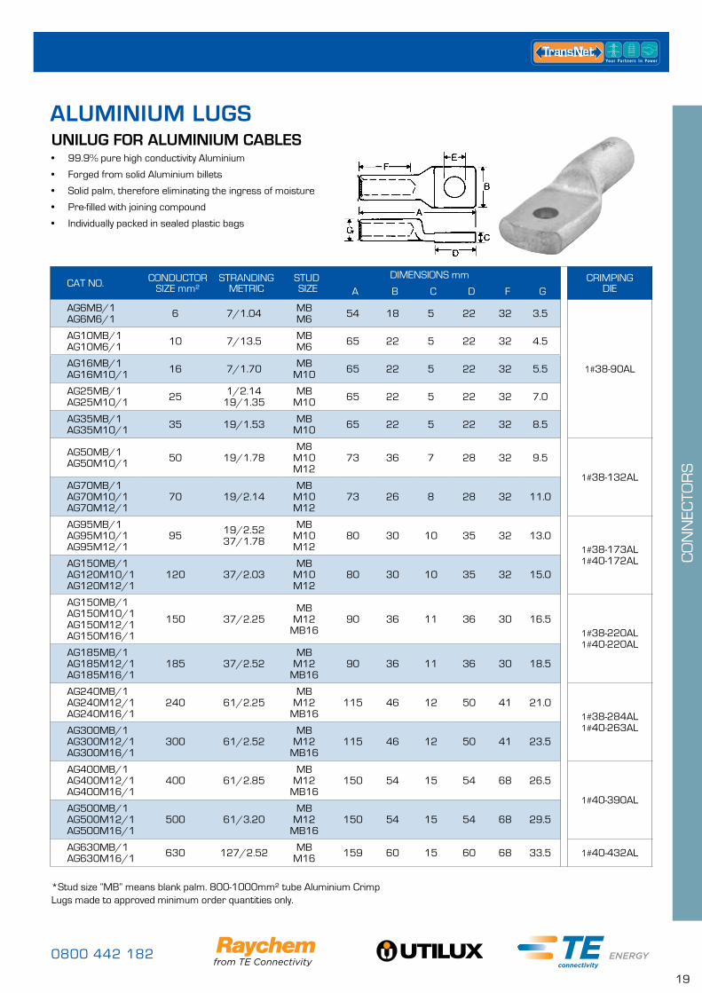
ALUMINIUM LUGSUNILUG FOR ALUMINIUM CABLES• 99.9% pure high conductivity Aluminium
• Forged from solid Aluminium billets
• Solid palm, therefore eliminating the ingress of moisture
• Pre-filled with joining compound
• Individually packed in sealed plastic bags
*Stud size “MB” means blank palm. 800-1000mm² tube Aluminium Crimp Lugs made to approved minimum order quantities only.
CAT NO. CONDUCTOR SIZE mm²
STRANDING METRIC
STUD SIZE
DIMENSIONS mm CRIMPING DIEA B C D F G
AG6MB/1 AG6M6/1 6 7/1.04 MB
M6 54 18 5 22 32 3.5
1#38-90AL
AG10MB/1 AG10M6/1 10 7/13.5 MB
M6 65 22 5 22 32 4.5
AG16MB/1 AG16M10/1 16 7/1.70 MB
M10 65 22 5 22 32 5.5
AG25MB/1 AG25M10/1 25 1/2.14
19/1.35MB
M10 65 22 5 22 32 7.0
AG35MB/1 AG35M10/1 35 19/1.53 MB
M10 65 22 5 22 32 8.5
AG50MB/1 AG50M10/1 50 19/1.78
M8 M10 M12
73 36 7 28 32 9.5
1#38-132ALAG70MB/1 AG70M10/1 AG70M12/1
70 19/2.14MB
M10 M12
73 26 8 28 32 11.0
AG95MB/1 AG95M10/1 AG95M12/1
95 19/2.52 37/1.78
MB M10 M12
80 30 10 35 32 13.01#38-173AL 1#40-172ALAG150MB/1
AG120M10/1 AG120M12/1
120 37/2.03MB
M10 M12
80 30 10 35 32 15.0
AG150MB/1 AG150M10/1 AG150M12/1 AG150M16/1
150 37/2.25MB
M12 MB16
90 36 11 36 30 16.51#38-220AL 1#40-220AL
AG185MB/1 AG185M12/1 AG185M16/1
185 37/2.52MB
M12 MB16
90 36 11 36 30 18.5
AG240MB/1 AG240M12/1 AG240M16/1
240 61/2.25MB
M12 MB16
115 46 12 50 41 21.01#38-284AL 1#40-263ALAG300MB/1
AG300M12/1 AG300M16/1
300 61/2.52MB
M12 MB16
115 46 12 50 41 23.5
AG400MB/1 AG400M12/1 AG400M16/1
400 61/2.85MB
M12 MB16
150 54 15 54 68 26.5
1#40-390ALAG500MB/1 AG500M12/1 AG500M16/1
500 61/3.20MB
M12 MB16
150 54 15 54 68 29.5
AG630MB/1 AG630M16/1 630 127/2.52 MB
M16 159 60 15 60 68 33.5 1#40-432AL
www.transnet.co.nz
20
CO
NN
ECTO
RS
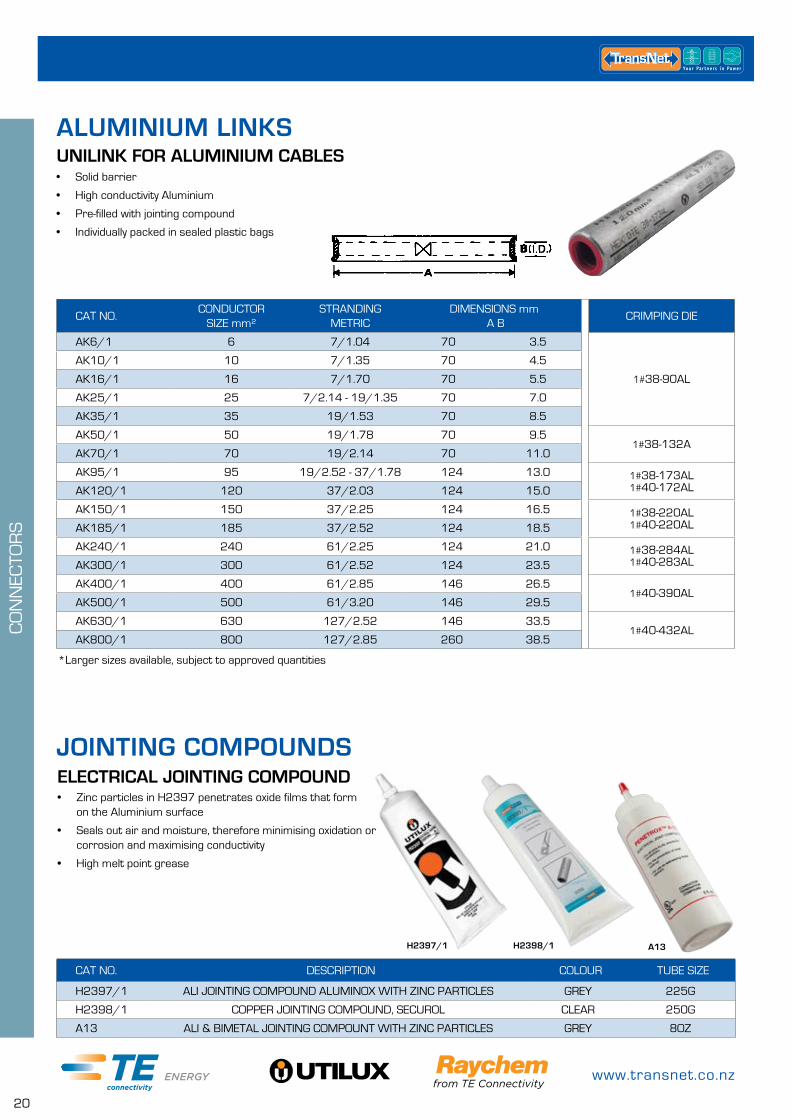
ELECTRICAL JOINTING COMPOUND• Zinc particles in H2397 penetrates oxide films that form
on the Aluminium surface
• Seals out air and moisture, therefore minimising oxidation or corrosion and maximising conductivity
• High melt point grease
*Larger sizes available, subject to approved quantities
H2397/1 H2398/1
CAT NO.CONDUCTOR
SIZE mm²STRANDING
METRICDIMENSIONS mm
A BCRIMPING DIE
AK6/1 6 7/1.04 70 3.5
1#38-90AL
AK10/1 10 7/1.35 70 4.5
AK16/1 16 7/1.70 70 5.5
AK25/1 25 7/2.14 - 19/1.35 70 7.0
AK35/1 35 19/1.53 70 8.5
AK50/1 50 19/1.78 70 9.51#38-132A
AK70/1 70 19/2.14 70 11.0
AK95/1 95 19/2.52 - 37/1.78 124 13.0 1#38-173AL 1#40-172ALAK120/1 120 37/2.03 124 15.0
AK150/1 150 37/2.25 124 16.5 1#38-220AL 1#40-220ALAK185/1 185 37/2.52 124 18.5
AK240/1 240 61/2.25 124 21.0 1#38-284AL 1#40-283ALAK300/1 300 61/2.52 124 23.5
AK400/1 400 61/2.85 146 26.51#40-390AL
AK500/1 500 61/3.20 146 29.5
AK630/1 630 127/2.52 146 33.51#40-432AL
AK800/1 800 127/2.85 260 38.5
UNILINK FOR ALUMINIUM CABLES• Solid barrier
• High conductivity Aluminium
• Pre-filled with jointing compound
• Individually packed in sealed plastic bags
CAT NO. DESCRIPTION COLOUR TUBE SIZE
H2397/1 ALI JOINTING COMPOUND ALUMINOX WITH ZINC PARTICLES GREY 225G
H2398/1 COPPER JOINTING COMPOUND, SECUROL CLEAR 250G
A13 ALI & BIMETAL JOINTING COMPOUNT WITH ZINC PARTICLES GREY 8OZ
A13
ALUMINIUM LINKS
JOINTING COMPOUNDS
0800 442 182
21
CO
NN
ECTO
RS
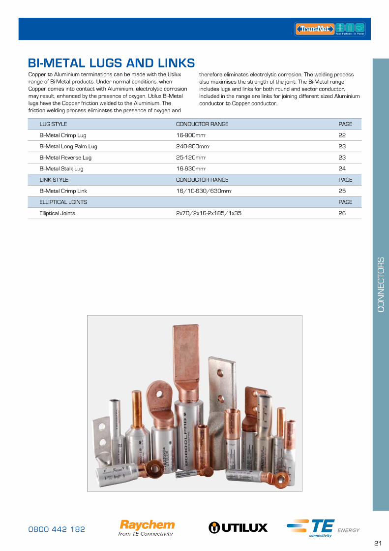
Copper to Aluminium terminations can be made with the Utilux range of Bi-Metal products. Under normal conditions, when Copper comes into contact with Aluminium, electrolytic corrosion may result, enhanced by the presence of oxygen. Utilux Bi-Metal lugs have the Copper friction welded to the Aluminium. The friction welding process eliminates the presence of oxygen and
LUG STYLE CONDUCTOR RANGE PAGE
Bi-Metal Crimp Lug 16-800mm² 22
Bi-Metal Long Palm Lug 240-800mm² 23
Bi-Metal Reverse Lug 25-120mm² 23
Bi-Metal Stalk Lug 16-630mm² 24
LINK STYLE CONDUCTOR RANGE PAGE
Bi-Metal Crimp Link 16/10-630/630mm² 25
ELLIPTICAL JOINTS PAGE
Elliptical Joints 2x70/2x16-2x185/1x35 26
BI-METAL LUGS AND LINKStherefore eliminates electrolytic corrosion. The welding process also maximises the strength of the joint. The Bi-Metal range includes lugs and links for both round and sector conductor. Included in the range are links for joining different sized Aluminium conductor to Copper conductor.
www.transnet.co.nz
22
CO
NN
ECTO
RS
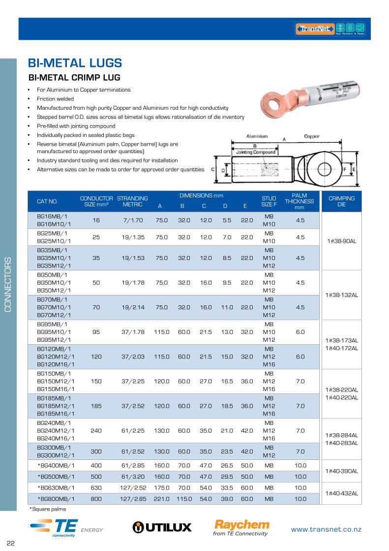
BI-METAL CRIMP LUG• For Aluminium to Copper terminations
• Friction welded
• Manufactured from high purity Copper and Aluminium rod for high conductivity
• Stepped barrel O.D. sizes across all bimetal lugs allows rationalisation of die inventory
• Pre-filled with jointing compound
• Individually packed in sealed plastic bags
• Reverse bimetal (Aluminium palm, Copper barrel) lugs are manufactured to approved order quantities)
• Industry standard tooling and dies required for installation
• Alternative sizes can be made to order for approved order quantities
*Square palms
CAT NO. CONDUCTOR SIZE mm²
STRANDING METRIC
DIMENSIONS mm STUD SIZE F
PALM THICKNESS
mm
CRIMPING DIEA B C D E
BG16MB/1BG16M10/1
16 7/1.70 75.0 32.0 12.0 5.5 22.0MB
M104.5
1#38-90ALBG25MB/1BG25M10/1
25 19/1.35 75.0 32.0 12.0 7.0 22.0MB
M104.5
BG35MB/1BG35M10/1BG35M12/1
35 19/1.53 75.0 32.0 12.0 8.5 22.0MB
M10M12
4.5
BG50MB/1BG50M10/1BG50M12/1
50 19/1.78 75.0 32.0 16.0 9.5 22.0MB
M10M12
4.5
1#38-132ALBG70MB/1BG70M10/1BG70M12/1
70 19/2.14 75.0 32.0 16.0 11.0 22.0MB
M10M12
4.5
BG95MB/1BG95M10/1BG95M12/1
95 37/1.78 115.0 60.0 21.5 13.0 32.0MB
M10M12
6.0
1#38-173AL1#40-172ALBG120MB/1
BG120M12/1BG120M16/1
120 37/2.03 115.0 60.0 21.5 15.0 32.0MB
M12M16
6.0
BG150MB/1BG150M12/1BG150M16/1
150 37/2.25 120.0 60.0 27.0 16.5 36.0MB
M12M16
7.0
1#38-220AL1#40-220ALBG185MB/1
BG185M12/1BG185M16/1
185 37/2.52 120.0 60.0 27.0 18.5 36.0MB
M12M16
7.0
BG240MB/1BG240M12/1BG240M16/1
240 61/2.25 130.0 60.0 35.0 21.0 42.0MB
M12M16
7.01#38-284AL1#40-283AL
BG300MB/1BG300M12/1
300 61/2.52 130.0 60.0 35.0 23.5 42.0MB
M127.0
*BG400MB/1 400 61/2.85 160.0 70.0 47.0 26.5 50.0 MB 10.01#40-390AL
*BG500MB/1 500 61/3.20 160.0 70.0 47.0 29.5 50.0 MB 10.0
*BG630MB/1 630 127/2.52 175.0 70.0 54.0 33.5 60.0 MB 10.01#40-432AL
*BG800MB/1 800 127/2.85 221.0 115.0 54.0 39.0 60.0 MB 10.0
BI-METAL LUGS
0800 442 182
23
CO
NN
ECTO
RS
BI-METAL REVERSE LUGS
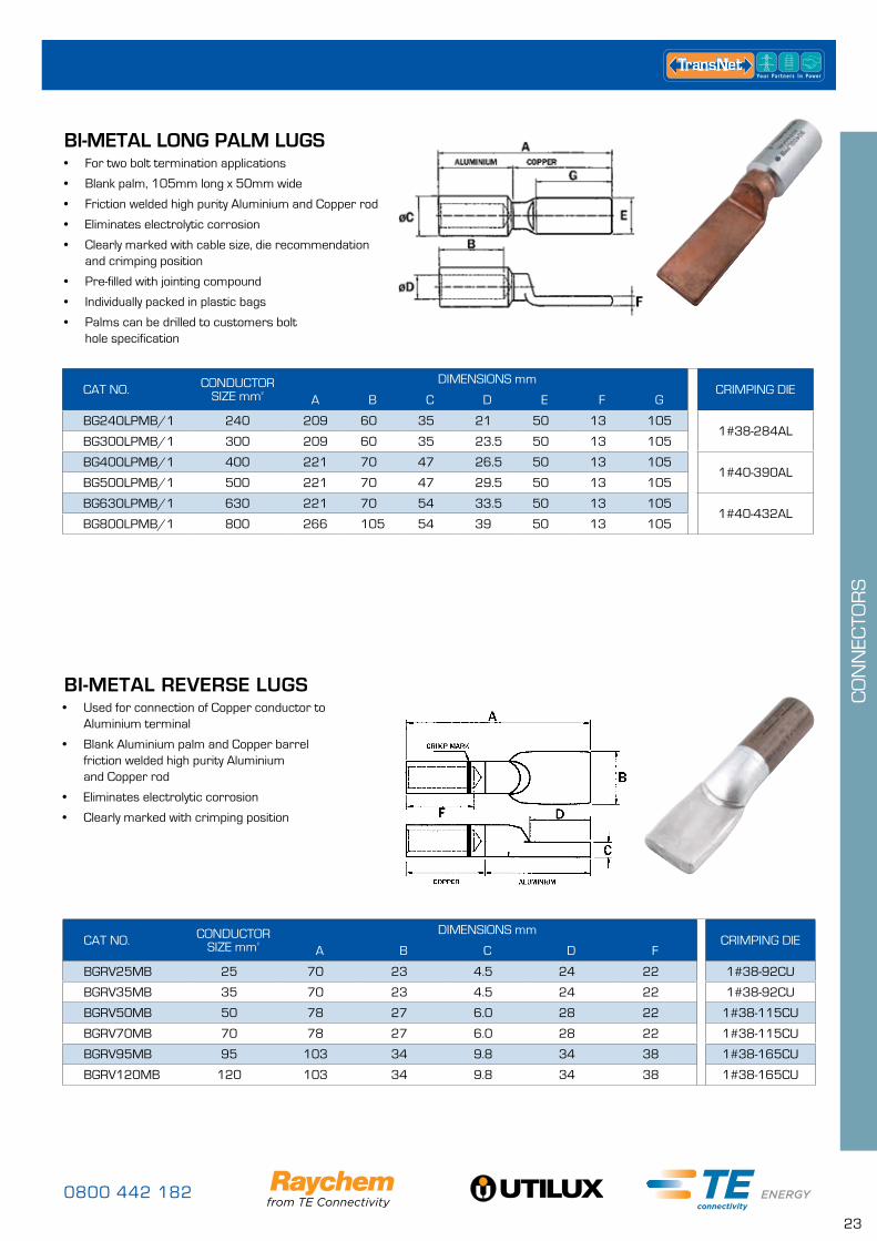
BI-METAL LONG PALM LUGS• For two bolt termination applications
• Blank palm, 105mm long x 50mm wide
• Friction welded high purity Aluminium and Copper rod
• Eliminates electrolytic corrosion
• Clearly marked with cable size, die recommendation and crimping position
• Pre-filled with jointing compound
• Individually packed in plastic bags
• Palms can be drilled to customers bolt hole specification
• Used for connection of Copper conductor to Aluminium terminal
• Blank Aluminium palm and Copper barrel friction welded high purity Aluminium and Copper rod
• Eliminates electrolytic corrosion
• Clearly marked with crimping position
CAT NO. CONDUCTOR SIZE mm²
DIMENSIONS mmCRIMPING DIE
A B C D E F G
BG240LPMB/1 240 209 60 35 21 50 13 1051#38-284AL
BG300LPMB/1 300 209 60 35 23.5 50 13 105
BG400LPMB/1 400 221 70 47 26.5 50 13 1051#40-390AL
BG500LPMB/1 500 221 70 47 29.5 50 13 105
BG630LPMB/1 630 221 70 54 33.5 50 13 1051#40-432AL
BG800LPMB/1 800 266 105 54 39 50 13 105
CAT NO. CONDUCTOR SIZE mm²
DIMENSIONS mmCRIMPING DIE
A B C D F
BGRV25MB 25 70 23 4.5 24 22 1#38-92CU
BGRV35MB 35 70 23 4.5 24 22 1#38-92CU
BGRV50MB 50 78 27 6.0 28 22 1#38-115CU
BGRV70MB 70 78 27 6.0 28 22 1#38-115CU
BGRV95MB 95 103 34 9.8 34 38 1#38-165CU
BGRV120MB 120 103 34 9.8 34 38 1#38-165CU
www.transnet.co.nz
24
CO
NN
ECTO
RS
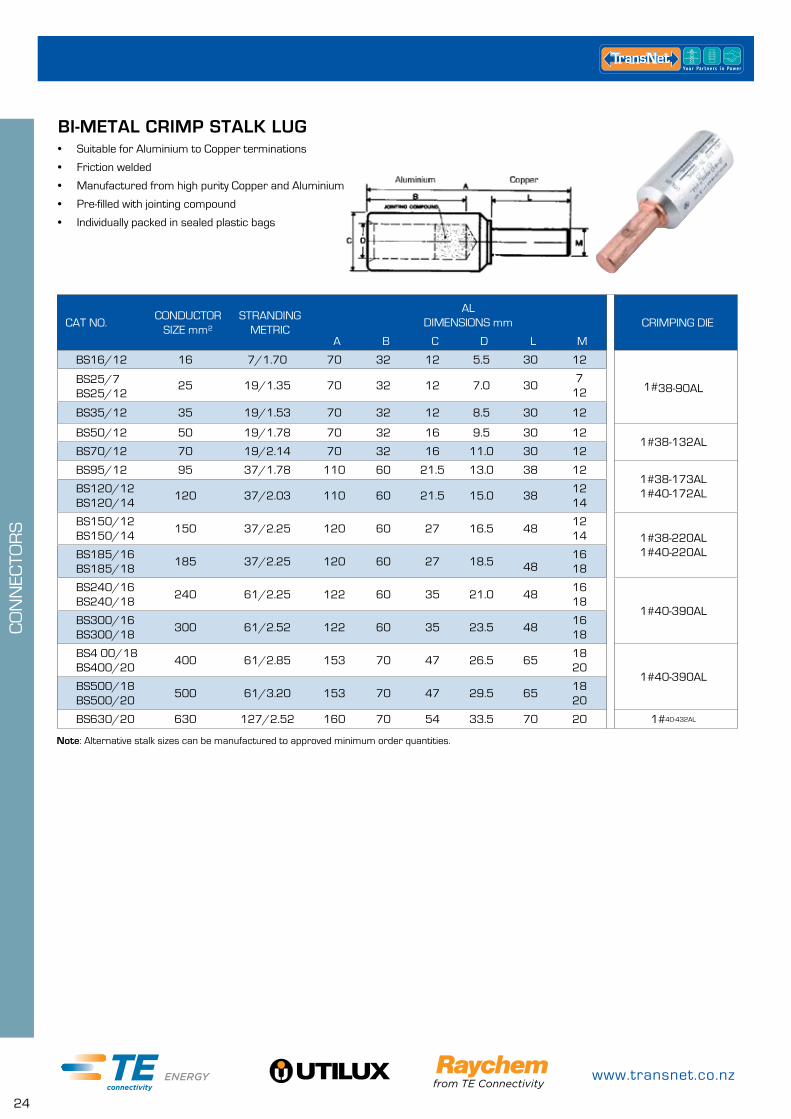
BI-METAL CRIMP STALK LUG
Note: Alternative stalk sizes can be manufactured to approved minimum order quantities.
• Suitable for Aluminium to Copper terminations
• Friction welded
• Manufactured from high purity Copper and Aluminium
• Pre-filled with jointing compound
• Individually packed in sealed plastic bags
CAT NO.CONDUCTOR
SIZE mm²STRANDING
METRIC
AL DIMENSIONS mm CRIMPING DIE
A B C D L M
BS16/12 16 7/1.70 70 32 12 5.5 30 12
1#38-90ALBS25/7 BS25/12
25 19/1.35 70 32 12 7.0 307
12
BS35/12 35 19/1.53 70 32 12 8.5 30 12
BS50/12 50 19/1.78 70 32 16 9.5 30 121#38-132AL
BS70/12 70 19/2.14 70 32 16 11.0 30 12
BS95/12 95 37/1.78 110 60 21.5 13.0 38 121#38-173AL 1#40-172ALBS120/12
BS120/14120 37/2.03 110 60 21.5 15.0 38
12 14
BS150/12 BS150/14
150 37/2.25 120 60 27 16.5 4812 14 1#38-220AL
1#40-220ALBS185/16 BS185/18
185 37/2.25 120 60 27 18.5 4816 18
BS240/16 BS240/18
240 61/2.25 122 60 35 21.0 4816 18
1#40-390ALBS300/16 BS300/18
300 61/2.52 122 60 35 23.5 4816 18
BS4 00/18 BS400/20
400 61/2.85 153 70 47 26.5 6518 20
1#40-390ALBS500/18 BS500/20
500 61/3.20 153 70 47 29.5 6518 20
BS630/20 630 127/2.52 160 70 54 33.5 70 20 1#40-432AL
0800 442 182
25
CO
NN
ECTO
RS
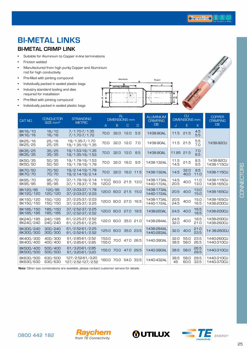
Note: Other size combinations are available, please contact customer service for details
BI-METAL CRIMP LINK• Suitable for Aluminium to Copper in-line terminations
• Friction welded
• Manufactured from high purity Copper and Aluminium rod for high conductivity
• Pre-filled with jointing compound
• Individually packed in sealed plastic bags
• Industry standard tooling and dies required for installation
• Pre-filled with jointing compound
• Individually packed in sealed plastic bags
CAT NO. CONDUCTOR SIZE mm²
STRANDING METRIC
AL DIMENSIONS mm
ALUMINIUM CRIMPING
DIE
CU DIMENSIONS mm
COPPER CRIMPING
DIEA B C D J E K
BK16/10BK16/16
16/1016/16
7/1.70-7/1.357/1.70-7/1.70 70.0 32.0 12.0 5.5 1#38-90AL 11.5 21.5 4.5
5.5
1#38-92CUBK25/16BK25/25
25/1625/25
19/1.35-7/1.7019/1.35-19/1.35 70.0 32.0 12.0 7.0 1#38-90AL 11.5 21.5 5.5
7.0
BK35/25BK35/35
35/2535/35
19/1.53-19/1.3519/1.35-19/1.53 70.0 32.0 12.0 8.5 1#38-90AL 11.85 21.5 7.0
8.5
BK50/35BK50/50
50/3550/50
19/1.78-19/1.5319/1.78-19/1.78 70.0 32.0 16.0 9.5 1#38-132AL 11.5
14.5 21.5 8.59.5
1#38-92CU1#38-115CU
BK70/50BK70/70
70/5070/70
19/2.14-19/1.7819/2.14-19/2.14 70.0 32.0 16.0 11.5 1#38-132AL 14.5 32.0
40.09.5
11.0 1#38-115CU
BK95/70BK95/95
95/7095/95
37/1.78-19/2.1437/1.78-37/1.78
110.0120.0 60.0 21.5 13.0 1#38-173AL
1#40-172AL14.520.5 40.0 11.0
13.01#38-115CU1#38-165CU
BK120/95BK120/120
120/95120/120
37/2.03-37/1.7837/2.03-37/2.03 120.0 60.0 21.5 15.0 1#38-173AL
1#40-172AL 20.5 40.0 13.015.0 1#38-165CU
BK150/120BK150/150
150/120150/150
37/2.25-37/2.0337/2.25-37/2.25 120.0 60.0 27.0 16.5 1#38-173AL
1#40-172AL20.524.5 40.0 15.0
16.51#38-165CU1#38-200CU
BK185/150BK185/185
185/150185/185
37/2.52-37/2.2537/2.52-37/2.52 120.0 60.0 27.0 18.5 1#38-220AL 24.5 40.0 16.5
18.5 1#38-200CU
BK240/185BK240/240
240/185240/240
61/2.25-37/2.5261/2.25-61/2.25 122.0 60.0 35.0 21.0 1#38-284AL 24.5
32.0 40.0 18.521.0
1#38-200CU1#38-260CU
BK300/240BK300/300
300/240300/300
61/2.52-61/2.2561/2.52-61/2.52 125.0 60.0 35.0 23.5 1#38-284AL
1#40-283AL 32.0 40.0 21.023.5 1# 38-260CU
BK400/300BK400/400
400/300400/400
61/2.85-61/2.5261/2.85-61/2.85
153.0155.0 70.0 47.0 26.5 1#40-390AL 32.0
38.555.058.0
23.526.5
1#40-260CU1#40-310CU
BK500/400BK500/500
500/400500/500
61/3.20-61/2.8561/3.20-61/3.20 155.0 70.0 47.0 29.5 1#40-390AL 38.5 58.0 26.5
29.5 1#40-310CU
BK630/500BK630/630
630/500630/630
127/2.52-61/3.20127/2.52-127/2.52 160.0 70.0 54.0 33.5 1#40-432AL 38.5
4558.060.0
29.533.5
1#40-310CU1#40-370CU
BI-METAL LINKS
www.transnet.co.nz
26
CO
NN
ECTO
RS
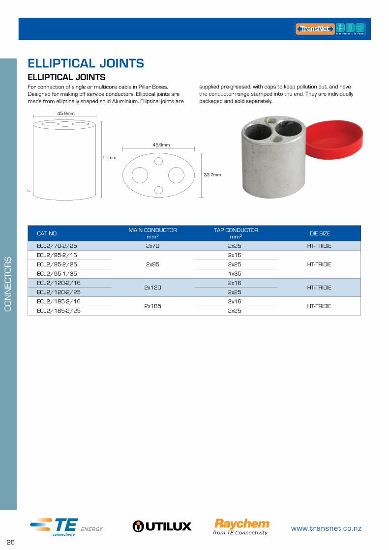
ELLIPTICAL JOINTS
CAT NO. MAIN CONDUCTOR mm²
TAP CONDUCTOR mm² DIE SIZE
ECJ2/70-2/25 2x70 2x25 HT-TRIDIE
ECJ2/95-2/16
2x95
2x16
HT-TRIDIEECJ2/95-2/25 2x25
ECJ2/95-1/35 1x35
ECJ2/120-2/162x120
2x16HT-TRIDIE
ECJ2/120-2/25 2x25
ECJ2/185-2/162x185
2x16HT-TRIDIE
ECJ2/185-2/25 2x25
45.9mm
50mm
45.9mm
33.7mm
For connection of single or multicore cable in Pillar Boxes. Designed for making off service conductors. Elliptical joints are made from elliptically shaped solid Aluminium. Elliptical joints are
supplied pre-greased, with caps to keep pollution out, and have the conductor range stamped into the end. They are individually packaged and sold separately.
ELLIPTICAL JOINTS
0800 442 182
27
CO
NN
ECTO
RS
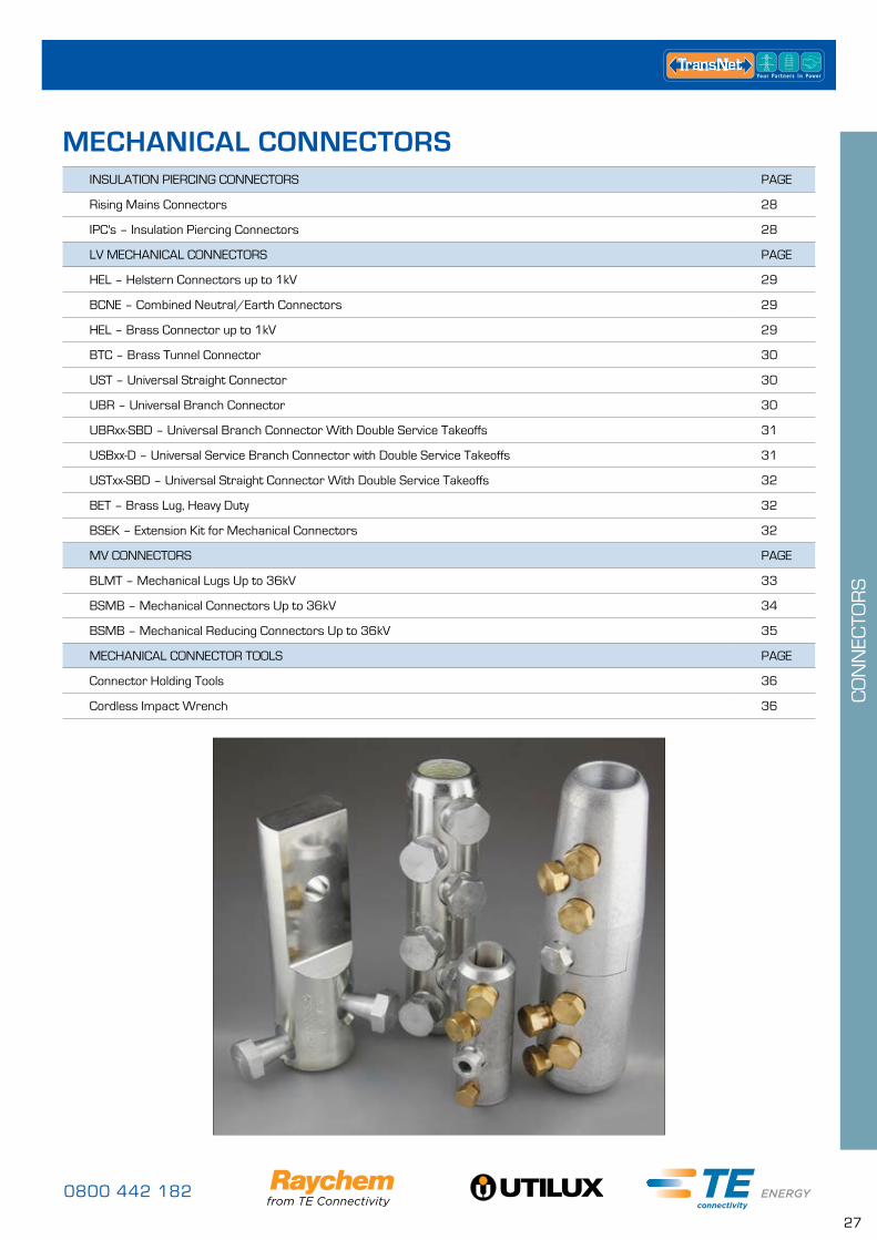
INSULATION PIERCING CONNECTORS PAGE
Rising Mains Connectors 28
IPC's – Insulation Piercing Connectors 28
LV MECHANICAL CONNECTORS PAGE
HEL – Helstern Connectors up to 1kV 29
BCNE – Combined Neutral/Earth Connectors 29
HEL – Brass Connector up to 1kV 29
BTC – Brass Tunnel Connector 30
UST – Universal Straight Connector 30
UBR – Universal Branch Connector 30
UBRxx-SBD – Universal Branch Connector With Double Service Takeoffs 31
USBxx-D – Universal Service Branch Connector with Double Service Takeoffs 31
USTxx-SBD – Universal Straight Connector With Double Service Takeoffs 32
BET – Brass Lug, Heavy Duty 32
BSEK – Extension Kit for Mechanical Connectors 32
MV CONNECTORS PAGE
BLMT – Mechanical Lugs Up to 36kV 33
BSMB – Mechanical Connectors Up to 36kV 34
BSMB – Mechanical Reducing Connectors Up to 36kV 35
MECHANICAL CONNECTOR TOOLS PAGE
Connector Holding Tools 36
Cordless Impact Wrench 36
MECHANICAL CONNECTORS
www.transnet.co.nz
28
CO
NN
ECTO
RS
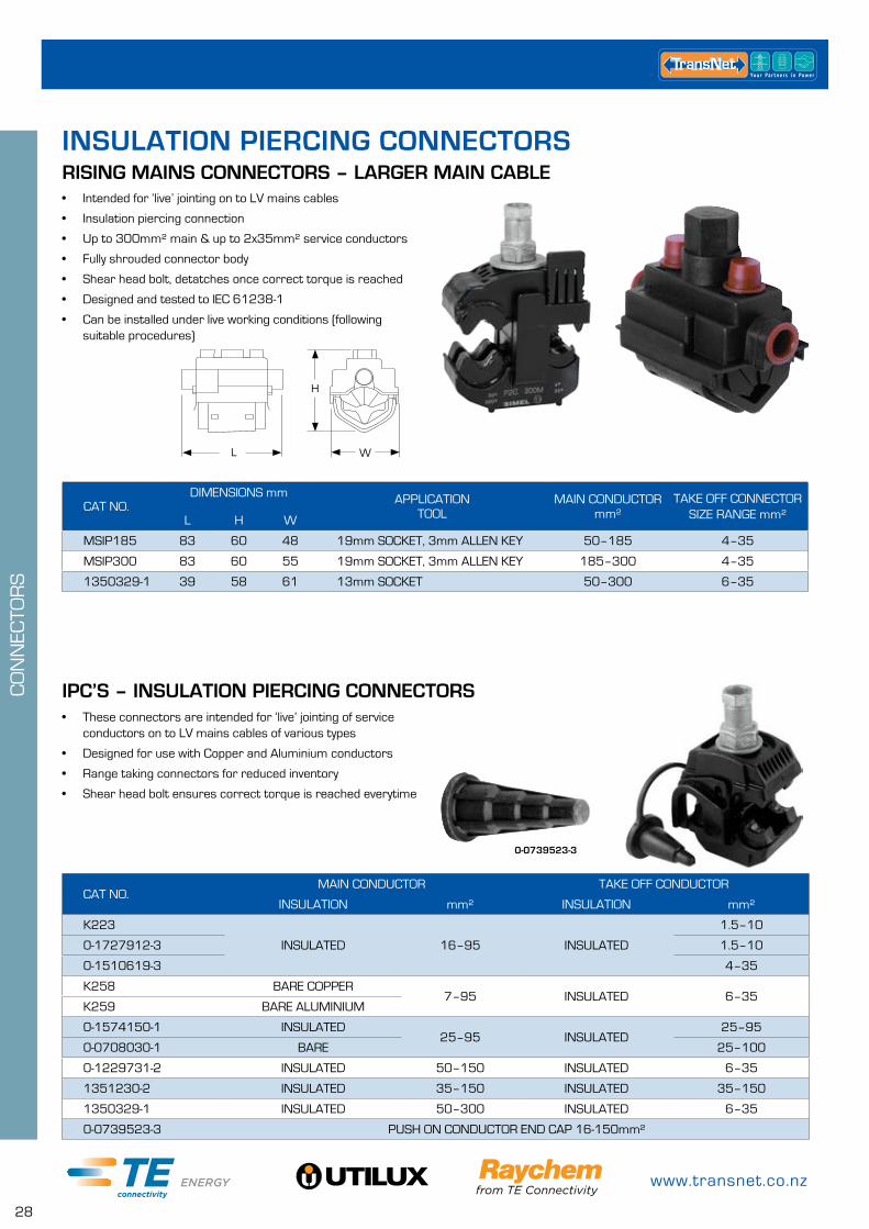
• Intended for ‘live’ jointing on to LV mains cables
• Insulation piercing connection
• Up to 300mm² main & up to 2x35mm² service conductors
• Fully shrouded connector body
• Shear head bolt, detatches once correct torque is reached
• Designed and tested to IEC 61238-1
• Can be installed under live working conditions (following suitable procedures)
RISING MAINS CONNECTORS – LARGER MAIN CABLE
CAT NO.DIMENSIONS mm APPLICATION
TOOLMAIN CONDUCTOR
mm²TAKE OFF CONNECTOR
SIZE RANGE mm²L H W
MSIP185 83 60 48 19mm SOCKET, 3mm ALLEN KEY 50–185 4–35
MSIP300 83 60 55 19mm SOCKET, 3mm ALLEN KEY 185–300 4–35
1350329-1 39 58 61 13mm SOCKET 50–300 6–35
H
WL
• These connectors are intended for ‘live’ jointing of service conductors on to LV mains cables of various types
• Designed for use with Copper and Aluminium conductors
• Range taking connectors for reduced inventory
• Shear head bolt ensures correct torque is reached everytime
IPC’S – INSULATION PIERCING CONNECTORS
CAT NO.MAIN CONDUCTOR TAKE OFF CONDUCTOR
INSULATION mm² INSULATION mm²
K223
INSULATED 16–95 INSULATED
1.5–10
0-1727912-3 1.5–10
0-1510619-3 4–35
K258 BARE COPPER7–95 INSULATED 6–35
K259 BARE ALUMINIUM
0-1574150-1 INSULATED25–95 INSULATED
25–95
0-0708030-1 BARE 25–100
0-1229731-2 INSULATED 50–150 INSULATED 6–35
1351230-2 INSULATED 35–150 INSULATED 35–150
1350329-1 INSULATED 50–300 INSULATED 6–35
0-0739523-3 PUSH ON CONDUCTOR END CAP 16-150mm²
0-0739523-3
INSULATION PIERCING CONNECTORS
0800 442 182
29
CO
NN
ECTO
RS
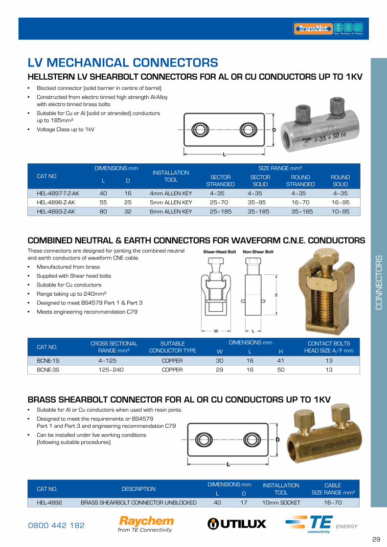
COMBINED NEUTRAL & EARTH CONNECTORS FOR WAVEFORM C.N.E. CONDUCTORSThese connectors are designed for jointing the combined neutral and earth conductors of waveform CNE cable.
• Manufactured from brass
• Supplied with Shear head bolts
• Suitable for Cu conductors
• Range taking up to 240mm²
• Designed to meet BS4579 Part 1 & Part 3
• Meets engineering recommendation C79
CAT NO.CROSS SECTIONAL
RANGE mm²SUITABLE
CONDUCTOR TYPEDIMENSIONS mm CONTACT BOLTS
HEAD SIZE A/F mmW L H
BCNE-1S 4–125 COPPER 30 16 41 13
BCNE-3S 125–240 COPPER 29 16 50 13
BRASS SHEARBOLT CONNECTOR FOR AL OR CU CONDUCTORS UP TO 1KV
CAT NO. DESCRIPTIONDIMENSIONS mm INSTALLATION
TOOLCABLE
SIZE RANGE mm²L D
HEL-4892 BRASS SHEARBOLT CONNECTOR UNBLOCKED 40 17 10mm SOCKET 16–70
• Suitable for Al or Cu conductors when used with resin joints
• Designed to meet the requirements or BS4579 Part 1 and Part 3 and engineering recommendation C79
• Can be installed under live working conditions (following suitable procedures)
LD
HELLSTERN LV SHEARBOLT CONNECTORS FOR AL OR CU CONDUCTORS UP TO 1KV• Blocked connector (solid barrier in centre of barrel)
• Constructed from electro tinned high strength Al-Alloy with electro tinned brass bolts
• Suitable for Cu or Al (solid or stranded) conductors up to 185mm²
• Voltage Class up to 1kV
CAT NO.DIMENSIONS mm
INSTALLATION TOOL
SIZE RANGE mm²
L DSECTOR
STRANDEDSECTOR SOLID
ROUND STRANDED
ROUND SOLID
HEL-4897-T-Z-AK 40 16 4mm ALLEN KEY 4–35 4–35 4–35 4–35
HEL-4896-Z-AK 55 25 5mm ALLEN KEY 25–70 35–95 16–70 16–95
HEL-4893-Z-AK 80 32 6mm ALLEN KEY 25–185 35–185 35–185 10–95
L
LV MECHANICAL CONNECTORS
www.transnet.co.nz
30
CO
NN
ECTO
RS
L
H
W
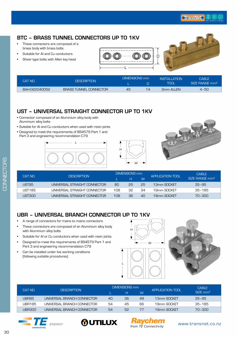
UST – UNIVERSAL STRAIGHT CONNECTOR UP TO 1KV• Connector composed of an Aluminium alloy body with
Aluminium alloy bolts
• Suitable for Al and Cu conductors when used with resin joints
• Designed to meet the requirements of BS4579 Part 1 and Part 3 and engineering recommendation C79
CAT NO. DESCRIPTIONDIMENSIONS mm
APPLICATION TOOLCABLE
SIZE RANGE mm²L H W
UST95 UNIVERSAL STRAIGHT CONNECTOR 80 25 25 13mm SOCKET 35–95
UST185 UNIVERSAL STRAIGHT CONNECTOR 108 32 34 19mm SOCKET 35–185
UST300 UNIVERSAL STRAIGHT CONNECTOR 108 36 40 19mm SOCKET 70–300
BTC – BRASS TUNNEL CONNECTORS UP TO 1KV• These connectors are composed of a
brass body with brass bolts
• Suitable for Al and Cu conductors
• Shear type bolts with Allen key head
CAT NO. DESCRIPTIONDIMENSIONS mm INSTALLATION
TOOLCABLE
SIZE RANGE mm²L D
BAH-022040052 BRASS TUNNEL CONNECTOR 45 14 3mm ALLEN 4–50
D
L
• A range of connectors for mains to mains connectors
• These connectors are composed of an Aluminium alloy body with Aluminium alloy bolts
• Suitable for Al or Cu conductors when used with resin joints
• Designed to meet the requirements of BS4579 Part 1 and Part 3 and engineering recommendation C79
• Can be installed under live working conditions (following suitable procedures)
UBR – UNIVERSAL BRANCH CONNECTOR UP TO 1KV
CAT NO. DESCRIPTIONDIMENSIONS mm
APPLICATION TOOLCABLE
SIZE mm²L H W
UBR95 UNIVERSAL BRANCH CONNECTOR 40 36 49 13mm SOCKET 35–95
UBR185 UNIVERSAL BRANCH CONNECTOR 54 45 66 19mm SOCKET 35–185
UBR300 UNIVERSAL BRANCH CONNECTOR 54 52 77 19mm SOCKET 70–300
L
H
W
0800 442 182
31
CO
NN
ECTO
RS
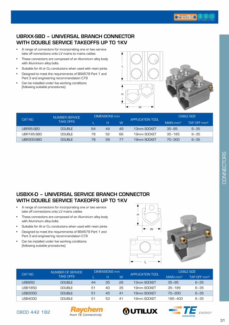
USBXX-D – UNIVERSAL SERVICE BRANCH CONNECTOR WITH DOUBLE SERVICE TAKEOFFS UP TO 1KV
CAT NO.NUMBER OF SERVICE
TAKE OFFSDIMENSIONS mm
APPLICATION TOOLCABLE SIZE
L H W MAIN mm² TAP OFF mm²
USB95D DOUBLE 44 35 26 13mm SOCKET 35–95 6–35
USB185D DOUBLE 51 40 35 19mm SOCKET 35–185 6–35
USB300D DOUBLE 51 45 41 19mm SOCKET 70–300 6–35
USB400D DOUBLE 51 53 41 19mm SOCKET 185–400 6–35
• A range of connectors for incorporating one or two service take off connections onto LV mains cables
• These connectors are composed of an Aluminium alloy body with Aluminium alloy bolts
• Suitable for Al or Cu conductors when used with resin joints
• Designed to meet the requirements of BS4579 Part 1 and Part 3 and engineering recommendation C79
• Can be installed under live working conditions (following suitable procedures)
H
W
L
UBRXX-SBD – UNIVERSAL BRANCH CONNECTOR WITH DOUBLE SERVICE TAKEOFFS UP TO 1KV• A range of connectors for incorporating one or two service
take off connections onto LV mains to mains cables
• These connectors are composed of an Aluminium alloy body with Aluminium alloy bolts
• Suitable for Al or Cu conductors when used with resin joints
• Designed to meet the requirements of BS4579 Part 1 and Part 3 and engineering recommendation C79
• Can be installed under live working conditions (following suitable procedures)
CAT NO.NUMBER SERVICE
TAKE OFFS
DIMENSIONS mmAPPLICATION TOOL
CABLE SIZE
L H W MAIN mm² TAP OFF mm²
UBR95-SBD DOUBLE 64 44 49 13mm SOCKET 35–95 6–35
UBR185-SBD DOUBLE 78 52 66 19mm SOCKET 35–185 6–35
UBR300-SBD DOUBLE 78 59 77 19mm SOCKET 70–300 6–35
H
W
L
www.transnet.co.nz
32
CO
NN
ECTO
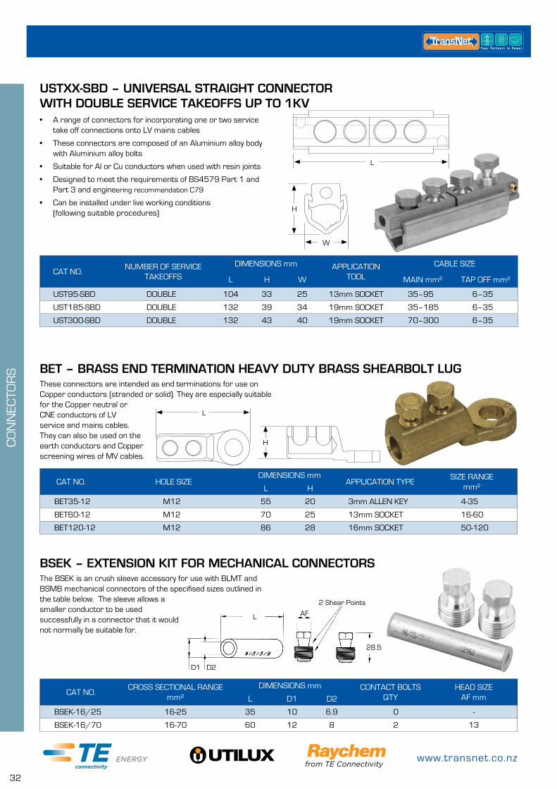
RS BET – BRASS END TERMINATION HEAVY DUTY BRASS SHEARBOLT LUG
BSEK – EXTENSION KIT FOR MECHANICAL CONNECTORS
These connectors are intended as end terminations for use on Copper conductors (stranded or solid). They are especially suitable for the Copper neutral or CNE conductors of LV service and mains cables. They can also be used on the earth conductors and Copper screening wires of MV cables.
The BSEK is an crush sleeve accessory for use with BLMT and BSMB mechanical connectors of the specifised sizes outlined in the table below. The sleeve allows a smaller conductor to be used successfully in a connector that it would not normally be suitable for.
CAT NO. HOLE SIZEDIMENSIONS mm
APPLICATION TYPESIZE RANGE
mm²L H
BET35-12 M12 55 20 3mm ALLEN KEY 4-35
BET60-12 M12 70 25 13mm SOCKET 16-60
BET120-12 M12 86 28 16mm SOCKET 50-120
CAT NO.CROSS SECTIONAL RANGE
mm²DIMENSIONS mm CONTACT BOLTS
QTYHEAD SIZE
AF mmL D1 D2
BSEK-16/25 16-25 35 10 6.9 0 -
BSEK-16/70 16-70 60 12 8 2 13
L
H
L AF
28.5
2 Shear Points
D1 D2
USTXX-SBD – UNIVERSAL STRAIGHT CONNECTOR WITH DOUBLE SERVICE TAKEOFFS UP TO 1KV• A range of connectors for incorporating one or two service
take off connections onto LV mains cables
• These connectors are composed of an Aluminium alloy body with Aluminium alloy bolts
• Suitable for Al or Cu conductors when used with resin joints
• Designed to meet the requirements of BS4579 Part 1 and Part 3 and engineering recommendation C79
• Can be installed under live working conditions (following suitable procedures)
CAT NO.NUMBER OF SERVICE
TAKEOFFS
DIMENSIONS mm APPLICATION TOOL
CABLE SIZE
L H W MAIN mm² TAP OFF mm²
UST95-SBD DOUBLE 104 33 25 13mm SOCKET 35–95 6–35
UST185-SBD DOUBLE 132 39 34 19mm SOCKET 35–185 6–35
UST300-SBD DOUBLE 132 43 40 19mm SOCKET 70–300 6–35
H
W
L
0800 442 182
33
CO
NN
ECTO
RS
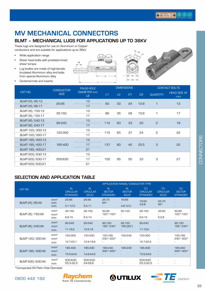
CAT NO.CONDUCTOR
SIZE
PALM HOLEDIAMETER mm
LB
DIMENSIONS CONTACT BOLTS
L1 L2 D1 D2 QUANTITYHEAD SIZE AF
mm
BLMT-25/95-1325-95
1360 30 24 12.8 1 13
BLMT-25/95-17 17
BLMT-35/150-1335-150
1386 35 28 15.8 1 17
BLMT-35/150-17 17
BLMT-95/240-1395-240
13112 60 33 20 2 19
BLMT-95/240-17 17
BLMT-120/300-13120-300
13115 65 37 24 2 22
BLMT-120/300-17 17
BLMT-185/400-13
185-400
13
137 80 42 25.5 3 22BLMT-185/400-17 17
BLMT-185/400-21 21
BLMT-500/630-13
500-630
13
150 95 50 33 3 27BLMT-500/630-17 17
BLMT-500/630-21 21
BLMT – MECHANICAL LUGS FOR APPLICATIONS UP TO 36KV
SELECTION AND APPLICATION TABLE
• Wide application range
• Shear head bolts with predetermined shear torque
• Lug bodies are made of high-tensile, tin-plated Aluminium alloy and bolts from special Aluminium alloy
• Centered hole and inserts
These lugs are designed for use on Aluminium or Copper conductors and are suitable for applications up to 36kV
*Compacted XX Palm Hole Diameter
CAT NO.
APPLICATION RANGE/CONDUCTOR TYPE
ALCIRCULAR STRANDED
ALCIRCULAR
SOLID
ALSECTOR
STRANDED
ALSECTOR SOLID
CU CIRCULAR STRANDED
CU CIRCULAR
SOLID
CU SECTOR
STRANDED
BLMT-25/95-XXmm²mmmm
25-95-5.7-12.5
25-95-5.5-11
25-7095*-
16-95-4.8-12.5
10-503.6-8
25-7095*
---
BLMT-35/150-XXmm²mm²mm
35-150-6.8-15
35-150-6.5-14
50-95120*-150*-
50-120--
35-150-6.6-15
35-50-6.5-8
50-95120*-150*-
BLMT-95/240-XXmm²mm²mm
95-240-11-19.2
95-240-10.5-18
95-150185*-240*-
95-150185 (90°)-
95-240-11-19.2
---
95-150185*-240*-
BLMT-120/300-XXmm²mm²mm
120-300-12.7-23.1
150-300-12.9-19.8
120-185240*-300*-
120-240--
120-300-12.7-22.6
---
120-185240*-300*-
BLMT-185/400-XXmm²mm²mm
185-400-15.5-24.6
185-400-14.8-24.6
185-240300*-400*-
185-240--
185-400-15.5-24.6
---
185-240300*-400*-
BLMT-500/630-XXmm²mm
500-63025.3-32.5
500-63024-28.6
--
--
500-63025.3-32.5
--
--
MV MECHANICAL CONNECTORS
www.transnet.co.nz
34
CO
NN
ECTO
RS
CAT NO.AL
CIRCULAR STRANDED
ALCIRCULAR
SOLID
ALSECTOR
STRANDED
ALSECTOR SOLID
CU CIRCULAR STRANDED
CU CIRCULAR
SOLID
CU SECTOR
STRANDED
BSMB-10/35mm²mm²mm
10-35-
3.7-7.5
10-50-
3.4-7.8
10-2535*
-
10-35--
10-35-
3.7-7.5
10-35-
3.4-6.7
10-2535*
-
BSMB-25/95mm²mm²mm
25-95-
5.7-12.5
25-95-
5.5-11
25-7095*
-
---
16-95-
4.8-12.5
10-50-
3.6-8
25-7095*
-
BSMB-35/150mm²mm²mm
35-150-
6.8-15
35-150-
6.5-14
50-95120-150*
-
50-120--
35-150-
6.6-15
---
50-95120-150*
-
BSMB-95/240mm²mm²mm
95-240-
11-19.2
95-240-
10.5-18
95-150185-240*
-
95-150185 (90°)
-
95-240-
11-19.2
---
95-150185-240*
-
BSMB-120/300mm²mm²mm
120-300-
12.7-23.1
150-300-
12.9-19.8
120-185240-300*
-
120-240--
120-300-
12.7-22.6
---
120-185240-300*
-
BSMB-185/400mm²mm²mm
185-400-
25.3-28.9
185-400-
24-25.1
185-240300-400*
185-240300 (90°)
-
185-400-
25.3-28.6
---
185-240300-400*
-
BSMB-500-MK2 mm²mm
50025.3-28.9
50024-25.1
--
--
50025.3-28.6
--
--
BSMB-630-MK2 mm²mm
63028.7-32.5
63027.3-28.4
--
--
63028.7-32.5
--
--
BSMB-800-MK2 mm²mm
80032.5-35.3
80030.9-32.1
--
--
80032.5-35.3
--
--
BSMB-1000-MK2 mm²mm
100037-39.3
100034.8-36
--
--
100037-39.5
--
--
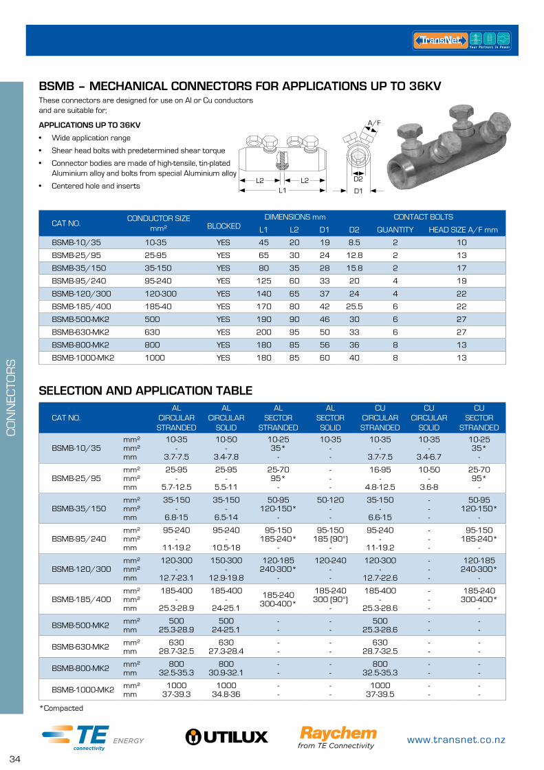
BSMB – MECHANICAL CONNECTORS FOR APPLICATIONS UP TO 36KV
SELECTION AND APPLICATION TABLE
APPLICATIONS UP TO 36KV
• Wide application range
• Shear head bolts with predetermined shear torque
• Connector bodies are made of high-tensile, tin-plated Aluminium alloy and bolts from special Aluminium alloy
• Centered hole and inserts
These connectors are designed for use on Al or Cu conductors and are suitable for;
*Compacted
L1L2L2 D2
A/F
D1
CAT NO.CONDUCTOR SIZE
mm² BLOCKED DIMENSIONS mm CONTACT BOLTS
L1 L2 D1 D2 QUANTITY HEAD SIZE A/F mm
BSMB-10/35 10-35 YES 45 20 19 8.5 2 10
BSMB-25/95 25-95 YES 65 30 24 12.8 2 13
BSMB-35/150 35-150 YES 80 35 28 15.8 2 17
BSMB-95/240 95-240 YES 125 60 33 20 4 19
BSMB-120/300 120-300 YES 140 65 37 24 4 22
BSMB-185/400 185-40 YES 170 80 42 25.5 6 22
BSMB-500-MK2 500 YES 190 90 46 30 6 27
BSMB-630-MK2 630 YES 200 95 50 33 6 27
BSMB-800-MK2 800 YES 180 85 56 36 8 13
BSMB-1000-MK2 1000 YES 180 85 60 40 8 13
0800 442 182
35
CO
NN
ECTO
RS
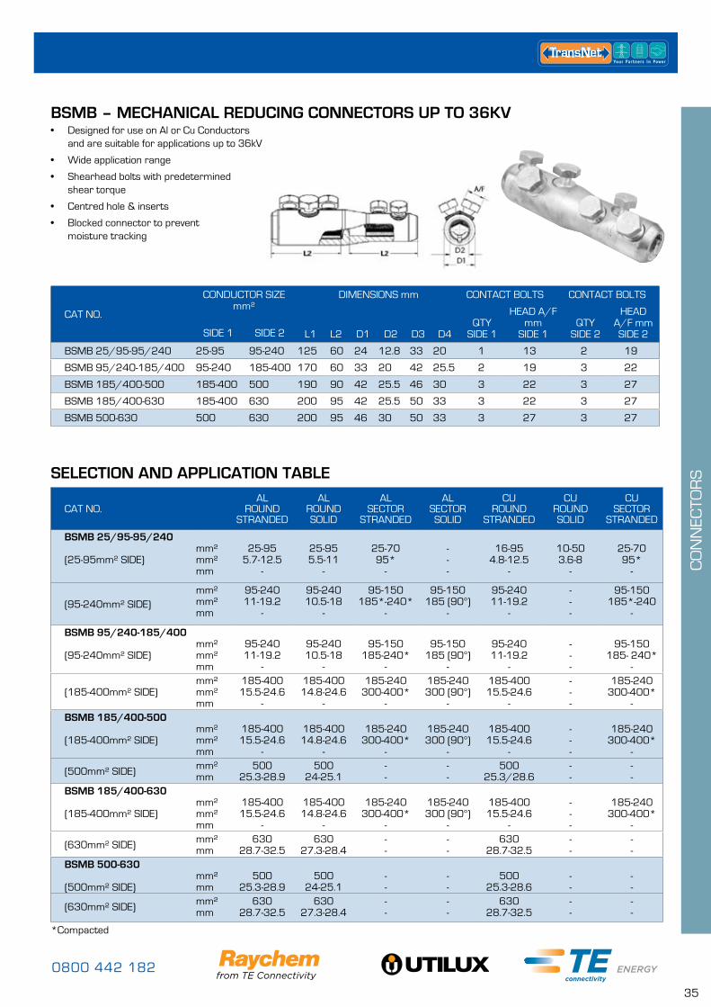
• Designed for use on Al or Cu Conductors and are suitable for applications up to 36kV
• Wide application range
• Shearhead bolts with predetermined shear torque
• Centred hole & inserts
• Blocked connector to prevent moisture tracking
*Compacted
CAT NO.
CONDUCTOR SIZE mm²
DIMENSIONS mm CONTACT BOLTS CONTACT BOLTS
L1 L2 D1 D2 D3 D4QTY
SIDE 1
HEAD A/F mm
SIDE 1QTY
SIDE 2
HEAD A/F mmSIDE 2SIDE 1 SIDE 2
BSMB 25/95-95/240 25-95 95-240 125 60 24 12.8 33 20 1 13 2 19
BSMB 95/240-185/400 95-240 185-400 170 60 33 20 42 25.5 2 19 3 22
BSMB 185/400-500 185-400 500 190 90 42 25.5 46 30 3 22 3 27
BSMB 185/400-630 185-400 630 200 95 42 25.5 50 33 3 22 3 27
BSMB 500-630 500 630 200 95 46 30 50 33 3 27 3 27
CAT NO.AL
ROUNDSTRANDED
AL ROUNDSOLID
AL SECTOR
STRANDED
AL SECTOR SOLID
CU ROUND
STRANDED
CU ROUND SOLID
CU SECTOR
STRANDED
BSMB 25/95-95/240 (25-95mm² SIDE)
mm²mm²mm
25-95
5.7-12.5 -
25-95 5.5-11
-
25-70 95*
-
---
16-95
4.8-12.5 -
10-50 3.6-8
-
25-70 95*
-
(95-240mm² SIDE)mm²mm²mm
95-240 11-19.2
-
95-240 10.5-18
-
95-150 185*-240*
-
95-150 185 (90°)
-
95-240 11-19.2
-
---
95-150 185*-240
-
BSMB 95/240-185/400 (95-240mm² SIDE)
mm²mm²mm
95-240 11-19.2
-
95-240 10.5-18
-
95-150
185-240*-
95-150
185 (90°)-
95-240 11-19.2
-
---
95-150
185- 240*-
(185-400mm² SIDE)mm²mm²mm
185-400 15.5-24.6
-
185-400 14.8-24.6
-
185-240 300-400*
-
185-240 300 (90°)
-
185-400 15.5-24.6
-
---
185-240 300-400*
-BSMB 185/400-500 (185-400mm² SIDE)
mm²mm²mm
185-400 15.5-24.6
-
185-400 14.8-24.6
-
185-240
300-400*-
185-240 300 (90°)
-
185-400 15.5-24.6
-
---
185-240
300-400*-
(500mm² SIDE) mm²mm
500 25.3-28.9
500 24-25.1
--
--
500 25.3/28.6
--
--
BSMB 185/400-630 (185-400mm² SIDE)
mm²mm²mm
185-400 15.5-24.6
-
185-400 14.8-24.6
-
185-240
300-400*-
185-240 300 (90°)
-
185-400 15.5-24.6
-
---
185-240
300-400*-
(630mm² SIDE) mm²mm
630 28.7-32.5
630 27.3-28.4
--
--
630 28.7-32.5
--
--
BSMB 500-630 (500mm² SIDE)
mm²mm
500
25.3-28.9500
24-25.1--
--
50025.3-28.6
--
--
(630mm² SIDE) mm²mm
63028.7-32.5
63027.3-28.4
--
--
63028.7-32.5
--
--
BSMB – MECHANICAL REDUCING CONNECTORS UP TO 36KV
SELECTION AND APPLICATION TABLE

www.transnet.co.nz
36
CO
NN
ECTO
RS
TransNet offers both an insulated and un-insulated holding tool for Mechanical Connectors. Both can be used for most connector sizes.
• Large easy grip handle
• Recommended for use on most sizes of connector to eliminate possible core ‘cranking’
• IT-10000-019 has a large jaw opening to accommodate a wide range of mechanical connectors
• 233 is insulated to 1000V
Cordless Impact Wrench IT-1000-023 for the installation of mechanical connectors and lugs using shear-head bolts.
CORDLESS IMPACT WRENCH
FEATURES
• Fan-cooled rare-earth magnet motor
• Convenient belt hook with integrated LED work light
• Externally accessible carbon brush and replaceable armature
• Stable compartmented carry case
• Simplified, safer and faster installation
• No additional device needed
• 1700g (~3.8 lbs) light, ergonomic and practical design
• Can be used for shear-head bolts up to 100Nm
• Powerful battery sufficient for approx. 20 four-bolted mechanical connectors per battery charging cycle
• Everything included for all standard mechanical connectors and lugs
INCLUDES
1 Battery charger, 2 Ni-MH battery 12V/2,6 Ah,1 Carry case, 1 Installation instruction,1/2'' hexagon socket sizes metric 10, 13, 17, 19, 22, 27, 1 Adaptor to 1/4'' hexagon drive, 2 hex head wrenches (Allen keys) metric 5, 6
CAT NO. DESCRIPTION
IT-1000-033CORDLESS IMPACT WRENCH FOR THE INSTALLATION OF MECHANICAL
CONNECTORS AND LUGS USING SHEAR-HEAD BOLTS
MECHANICAL CONNECTOR HOLDING TOOLS
CAT NO. DESCRIPTION
IT-1000-019 UNIVERSAL HOLDING TOOL FOR MECHANICAL CONNECTORS
223 1000V INSULATED MECHANICAL CONNECTOR HOLDER
MECHANICAL CONNECTOR TOOLS
0800 442 182
37
CO
NN
ECTO
RS
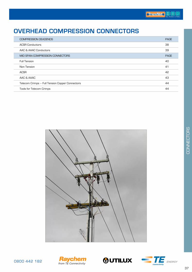
COMPRESSION DEADENDS PAGE
ACSR Conductors 38
AAC & AAAC Conductors 39
MID SPAN COMPRESSION CONNECTORS PAGE
Full Tension 40
Non Tension 41
ACSR 42
AAC & AAAC 43
Telecom Crimps – Full Tension Copper Connectors 44
Tools for Telecom Crimps 44
OVERHEAD COMPRESSION CONNECTORS
www.transnet.co.nz
38
CO
NN
ECTO
RS
=
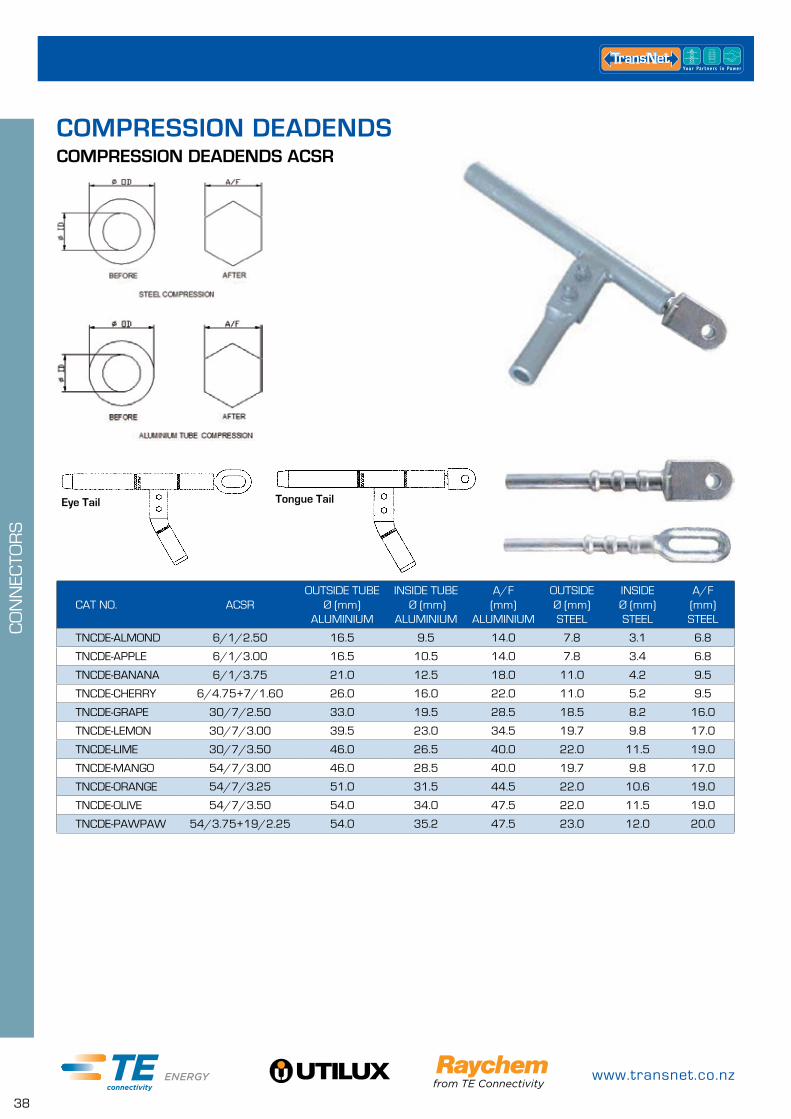
Tongue Tail
COMPRESSION DEADENDS ACSR
CAT NO. ACSROUTSIDE TUBE
Ø (mm) ALUMINIUM
INSIDE TUBE Ø (mm)
ALUMINIUM
A/F (mm)
ALUMINIUM
OUTSIDE Ø (mm) STEEL
INSIDE Ø (mm) STEEL
A/F (mm) STEEL
TNCDE-ALMOND 6/1/2.50 16.5 9.5 14.0 7.8 3.1 6.8
TNCDE-APPLE 6/1/3.00 16.5 10.5 14.0 7.8 3.4 6.8
TNCDE-BANANA 6/1/3.75 21.0 12.5 18.0 11.0 4.2 9.5
TNCDE-CHERRY 6/4.75+7/1.60 26.0 16.0 22.0 11.0 5.2 9.5
TNCDE-GRAPE 30/7/2.50 33.0 19.5 28.5 18.5 8.2 16.0
TNCDE-LEMON 30/7/3.00 39.5 23.0 34.5 19.7 9.8 17.0
TNCDE-LIME 30/7/3.50 46.0 26.5 40.0 22.0 11.5 19.0
TNCDE-MANGO 54/7/3.00 46.0 28.5 40.0 19.7 9.8 17.0
TNCDE-ORANGE 54/7/3.25 51.0 31.5 44.5 22.0 10.6 19.0
TNCDE-OLIVE 54/7/3.50 54.0 34.0 47.5 22.0 11.5 19.0
TNCDE-PAWPAW 54/3.75+19/2.25 54.0 35.2 47.5 23.0 12.0 20.0
COMPRESSION DEADENDS
Eye Tail
0800 442 182
39
CO
NN
ECTO
RS
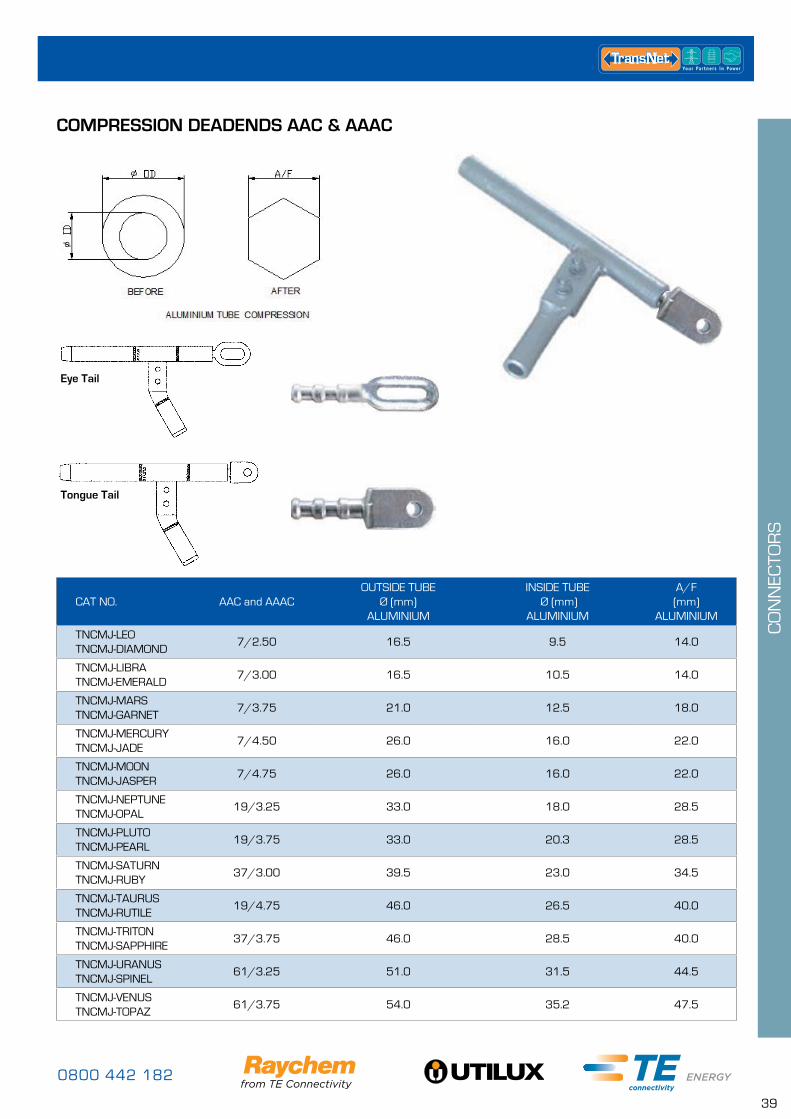
Eye Tail
Tongue Tail
COMPRESSION DEADENDS AAC & AAAC
CAT NO. AAC and AAACOUTSIDE TUBE
Ø (mm) ALUMINIUM
INSIDE TUBE Ø (mm)
ALUMINIUM
A/F (mm)
ALUMINIUM
TNCMJ-LEOTNCMJ-DIAMOND
7/2.50 16.5 9.5 14.0
TNCMJ-LIBRATNCMJ-EMERALD
7/3.00 16.5 10.5 14.0
TNCMJ-MARSTNCMJ-GARNET
7/3.75 21.0 12.5 18.0
TNCMJ-MERCURYTNCMJ-JADE
7/4.50 26.0 16.0 22.0
TNCMJ-MOONTNCMJ-JASPER
7/4.75 26.0 16.0 22.0
TNCMJ-NEPTUNETNCMJ-OPAL
19/3.25 33.0 18.0 28.5
TNCMJ-PLUTOTNCMJ-PEARL
19/3.75 33.0 20.3 28.5
TNCMJ-SATURNTNCMJ-RUBY
37/3.00 39.5 23.0 34.5
TNCMJ-TAURUSTNCMJ-RUTILE
19/4.75 46.0 26.5 40.0
TNCMJ-TRITONTNCMJ-SAPPHIRE
37/3.75 46.0 28.5 40.0
TNCMJ-URANUSTNCMJ-SPINEL
61/3.25 51.0 31.5 44.5
TNCMJ-VENUSTNCMJ-TOPAZ
61/3.75 54.0 35.2 47.5
www.transnet.co.nz
40
CO
NN
ECTO
RS
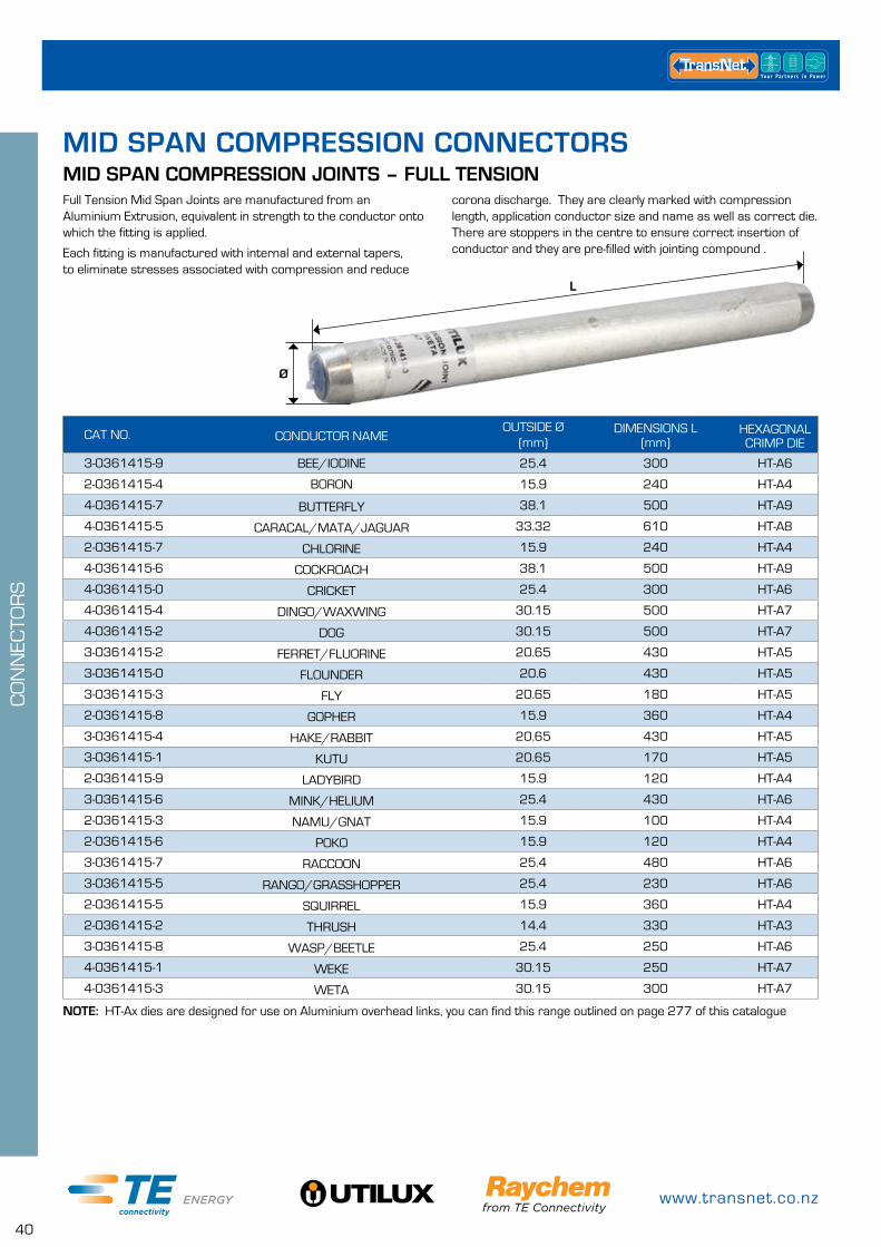
Full Tension Mid Span Joints are manufactured from an Aluminium Extrusion, equivalent in strength to the conductor onto which the fitting is applied.
Each fitting is manufactured with internal and external tapers, to eliminate stresses associated with compression and reduce
CAT NO. CONDUCTOR NAMEOUTSIDE Ø
(mm)DIMENSIONS L
(mm)HEXAGONAL CRIMP DIE
3-0361415-9 BEE/IODINE 25.4 300 HT-A6
2-0361415-4 BORON 15.9 240 HT-A4
4-0361415-7 BUTTERFLY 38.1 500 HT-A9
4-0361415-5 CARACAL/MATA/JAGUAR 33.32 610 HT-A8
2-0361415-7 CHLORINE 15.9 240 HT-A4
4-0361415-6 COCKROACH 38.1 500 HT-A9
4-0361415-0 CRICKET 25.4 300 HT-A6
4-0361415-4 DINGO/WAXWING 30.15 500 HT-A7
4-0361415-2 DOG 30.15 500 HT-A7
3-0361415-2 FERRET/FLUORINE 20.65 430 HT-A5
3-0361415-0 FLOUNDER 20.6 430 HT-A5
3-0361415-3 FLY 20.65 180 HT-A5
2-0361415-8 GOPHER 15.9 360 HT-A4
3-0361415-4 HAKE/RABBIT 20.65 430 HT-A5
3-0361415-1 KUTU 20.65 170 HT-A5
2-0361415-9 LADYBIRD 15.9 120 HT-A4
3-0361415-6 MINK/HELIUM 25.4 430 HT-A6
2-0361415-3 NAMU/GNAT 15.9 100 HT-A4
2-0361415-6 POKO 15.9 120 HT-A4
3-0361415-7 RACCOON 25.4 480 HT-A6
3-0361415-5 RANGO/GRASSHOPPER 25.4 230 HT-A6
2-0361415-5 SQUIRREL 15.9 360 HT-A4
2-0361415-2 THRUSH 14.4 330 HT-A3
3-0361415-8 WASP/BEETLE 25.4 250 HT-A6
4-0361415-1 WEKE 30.15 250 HT-A7
4-0361415-3 WETA 30.15 300 HT-A7
MID SPAN COMPRESSION JOINTS – FULL TENSIONcorona discharge. They are clearly marked with compression length, application conductor size and name as well as correct die. There are stoppers in the centre to ensure correct insertion of conductor and they are pre-filled with jointing compound .
MID SPAN COMPRESSION CONNECTORS
L
Ø
NOTE: HT-Ax dies are designed for use on Aluminium overhead links, you can find this range outlined on page 277 of this catalogue
0800 442 182
41
CO
NN
ECTO
RS
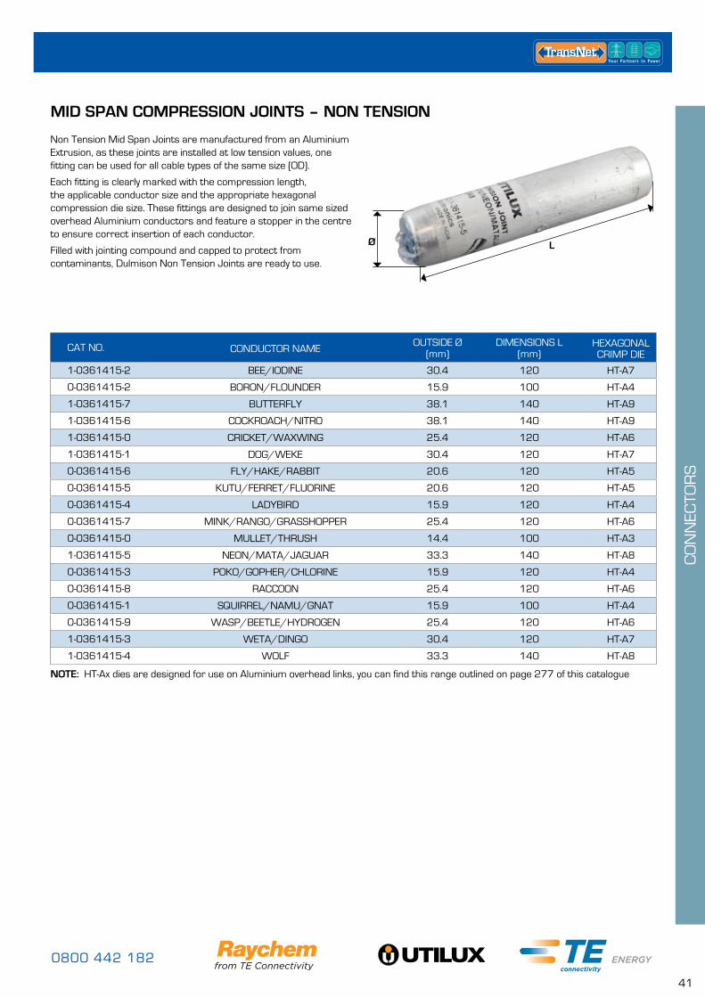
MID SPAN COMPRESSION JOINTS – NON TENSION
Non Tension Mid Span Joints are manufactured from an Aluminium Extrusion, as these joints are installed at low tension values, one fitting can be used for all cable types of the same size (OD).
Each fitting is clearly marked with the compression length, the applicable conductor size and the appropriate hexagonal compression die size. These fittings are designed to join same sized overhead Aluminium conductors and feature a stopper in the centre to ensure correct insertion of each conductor.
Filled with jointing compound and capped to protect from contaminants, Dulmison Non Tension Joints are ready to use.
Ø L
CAT NO. CONDUCTOR NAMEOUTSIDE Ø
(mm)DIMENSIONS L
(mm)HEXAGONAL CRIMP DIE
1-0361415-2 BEE/IODINE 30.4 120 HT-A7
0-0361415-2 BORON/FLOUNDER 15.9 100 HT-A4
1-0361415-7 BUTTERFLY 38.1 140 HT-A9
1-0361415-6 COCKROACH/NITRO 38.1 140 HT-A9
1-0361415-0 CRICKET/WAXWING 25.4 120 HT-A6
1-0361415-1 DOG/WEKE 30.4 120 HT-A7
0-0361415-6 FLY/HAKE/RABBIT 20.6 120 HT-A5
0-0361415-5 KUTU/FERRET/FLUORINE 20.6 120 HT-A5
0-0361415-4 LADYBIRD 15.9 120 HT-A4
0-0361415-7 MINK/RANGO/GRASSHOPPER 25.4 120 HT-A6
0-0361415-0 MULLET/THRUSH 14.4 100 HT-A3
1-0361415-5 NEON/MATA/JAGUAR 33.3 140 HT-A8
0-0361415-3 POKO/GOPHER/CHLORINE 15.9 120 HT-A4
0-0361415-8 RACCOON 25.4 120 HT-A6
0-0361415-1 SQUIRREL/NAMU/GNAT 15.9 100 HT-A4
0-0361415-9 WASP/BEETLE/HYDROGEN 25.4 120 HT-A6
1-0361415-3 WETA/DINGO 30.4 120 HT-A7
1-0361415-4 WOLF 33.3 140 HT-A8
NOTE: HT-Ax dies are designed for use on Aluminium overhead links, you can find this range outlined on page 277 of this catalogue
www.transnet.co.nz
42
CO
NN
ECTO
RS
CAT NO. ACSROUTSIDE TUBE
Ø (mm) ALUMINIUM
INSIDE TUBE Ø (mm)
ALUMINIUM
A/F (mm)
ALUMINIUM
OUTSIDE Ø (mm) STEEL
INSIDE Ø (mm) STEEL
A/F (mm) STEEL
TNCMJ-ALMOND 6/1/2.50 16.5 9.5 14.0 7.8 3.1 6.8
TNCMJ-APPLE 6/1/3.00 16.5 10.5 14.0 7.8 3.4 6.8
TNCMJ-BANANA 6/1/3.75 21.0 12.5 18.0 11.0 4.2 9.5
TNCMJ-CHERRY 6/4.75+7/1.60 26.0 16.0 22.0 11.0 5.2 9.5
TNCMJE-GRAPE 30/7/2.50 33.0 19.5 28.5 18.5 8.2 16.0
TNCMJ-LEMON 30/7/3.00 39.5 23.0 34.5 19.7 9.8 17.0
TNCMJ-LIME 30/7/3.50 46.0 26.5 40.0 22.0 11.5 19.0
TNCMJ-MANGO 54/7/3.00 46.0 28.5 40.0 19.7 9.8 17.0
TNCMJ-ORANGE 54/7/3.25 51.0 31.5 44.5 22.0 10.6 19.0
TNCMJ-OLIVE 54/7/3.50 54.0 34.0 47.5 22.0 11.5 19.0
TNCMJ-PAWPAW 54/3.75+19/2.25 54.0 35.2 47.5 23.0 12.0 20.0
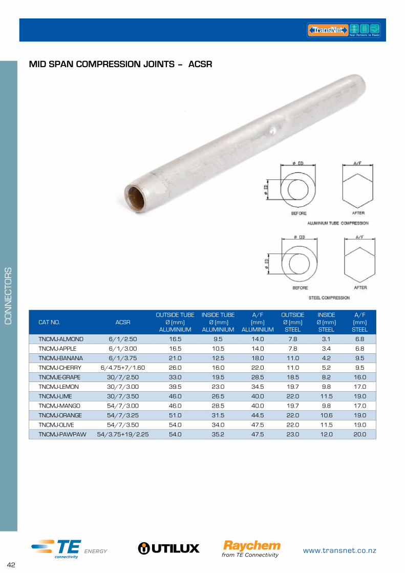
MID SPAN COMPRESSION JOINTS – ACSR
0800 442 182
43
CO
NN
ECTO
RS
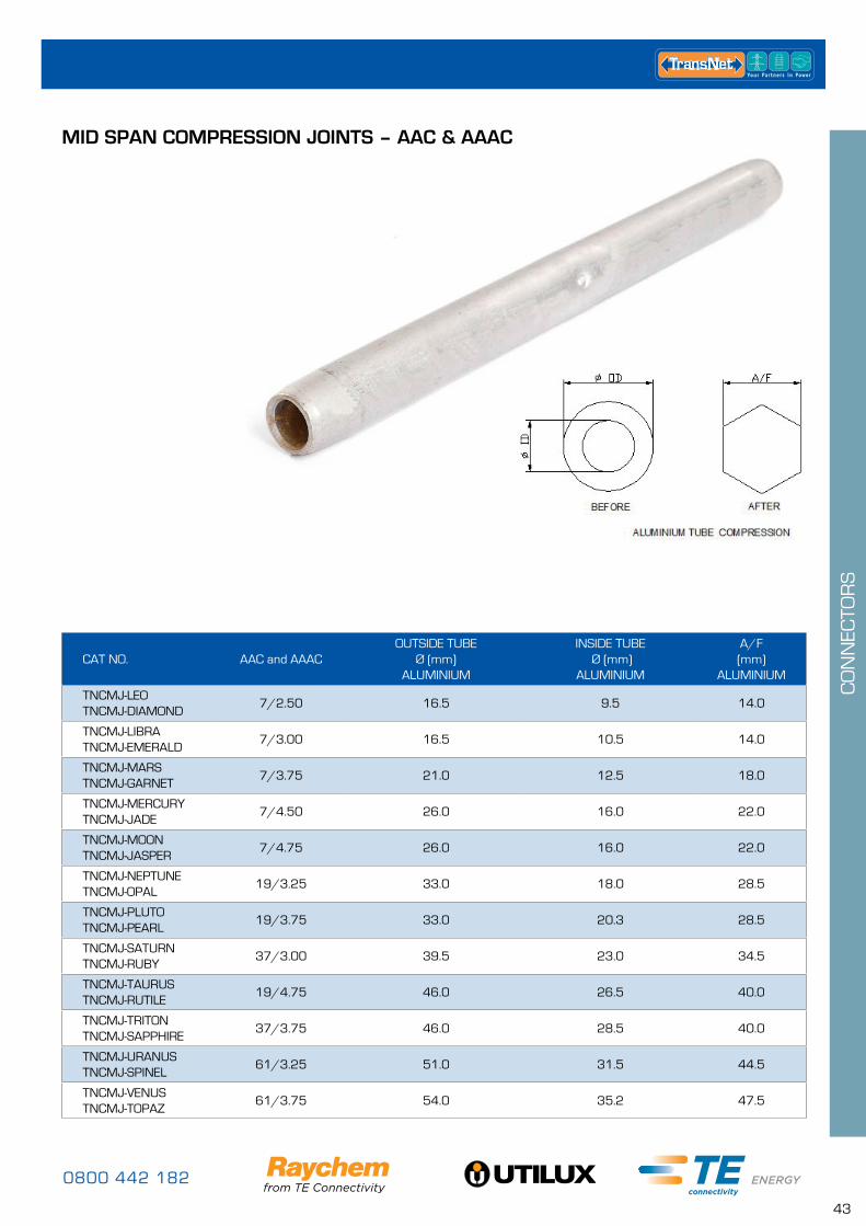
MID SPAN COMPRESSION JOINTS – AAC & AAAC
CAT NO. AAC and AAACOUTSIDE TUBE
Ø (mm) ALUMINIUM
INSIDE TUBE Ø (mm)
ALUMINIUM
A/F (mm)
ALUMINIUM
TNCMJ-LEOTNCMJ-DIAMOND
7/2.50 16.5 9.5 14.0
TNCMJ-LIBRATNCMJ-EMERALD
7/3.00 16.5 10.5 14.0
TNCMJ-MARSTNCMJ-GARNET
7/3.75 21.0 12.5 18.0
TNCMJ-MERCURYTNCMJ-JADE
7/4.50 26.0 16.0 22.0
TNCMJ-MOONTNCMJ-JASPER
7/4.75 26.0 16.0 22.0
TNCMJ-NEPTUNETNCMJ-OPAL
19/3.25 33.0 18.0 28.5
TNCMJ-PLUTOTNCMJ-PEARL
19/3.75 33.0 20.3 28.5
TNCMJ-SATURNTNCMJ-RUBY
37/3.00 39.5 23.0 34.5
TNCMJ-TAURUSTNCMJ-RUTILE
19/4.75 46.0 26.5 40.0
TNCMJ-TRITONTNCMJ-SAPPHIRE
37/3.75 46.0 28.5 40.0
TNCMJ-URANUSTNCMJ-SPINEL
61/3.25 51.0 31.5 44.5
TNCMJ-VENUSTNCMJ-TOPAZ
61/3.75 54.0 35.2 47.5

www.transnet.co.nz
44
CO
NN
ECTO
RS
CAT NO.STRANDING
IMPERIALCONNECTOR DIMENSIONS CRIMP GROOVE
SIZE mmTOOL NO.
CRIMPS PER CONNECTORO.D. mm LENGTH mm
TDCS1/100 7/.044 6.35 38 6.35 TY635794/1, TR794952 4
TECS1/50 7/.052 7.94 64 7.94 TY635794/1, TR794952 8
TECS2/50 7/.064 7.94 64 7.94 TY635794/1, TR794952 8
TFCS1/50 7/.080 9.52 76 9.52 TR794952, TR9521270 8
TFCS2/50 19/.052 9.52 76 9.52 TR794952, TR9521270 8
TFCS3/50 7/.083 9.52 76 9.52 TR794952, TR9521270 8
TGCS3/50 19/.064 12.70 89 12.70 TR794952, TR9521270 10
THCS2/50 19/.083 15.88 127 15.88 38-130CU 14
TJCS1/1 19/.101 22.22 203 19.25 38-193CU 8
TJCS2/1 37/.072 22.22 203 19.25 38-193CU 8
TKCS2/1 37/.083 25.40 254 22.00 38-220CU 12
CAT NO.STRANDING
IMPERIALCONDUCTOR
SIZE mm²CONNECTOR DIMENSIONS CRIMP
GROOVE SIZE mm
TOOL NO.CRIMPS PER CONNECTORO.D. mm LENGTH mm
TDCSM2/100 7/1.04 6 6.35 38 6.35 TY635794/1, TR794952 4
TECSM1/50 7/1.35 10 7.94 64 7.94 TY635794/1, TR794952 8
TECSM2/50 7/1.70 16 7.94 64 7.94 TY635794/1, TR794952 8
TFCSM1/50 7/2.14 25 9.52 76 9.52 TR794952, TR9521270 8
TFCSM2/50 19/1.35 35 9.52 76 9.52 TR794952, TR9521270 8
TGCSM2/50 19/1.53 – 12.70 89 12.70 TR794952, TR9521270 10
THCSM2/50 19/1.78 50 15.88 127 15.88 38-130CU 14
THCSM3/50 19/2.14 70 15.88 127 15.88 38-130CU 14
IMPERIAL
METRIC
• Connector Material – Copper, metal sprayed internally
• Superior tensile strength
• Considerable reduction in mass of finished joint
• Elimination of corrosion
• Also known as MS Telecom Sleeves
TELECOM CRIMPS – FULL TENSION COPPER CONNECTORS IMPERIAL & METRIC
Available in various crimp groove size combinations. The complete range is adjustable and robust. All models are supplied complete with adjusting key and “Go, No Go” gauge to ensure a perfect crimp every time.
UTILUX MS-TELECOM SLEEVE CRIMP TOOL
• Designed for use with Utilux MS – Telecom sleeves
CAT NO. CRIMP GROOVE SIZES mm
TY635794/1 6.35 & 7.94
TR794952 7.94 & 9.52
TR9521270 9.52 & 12.70
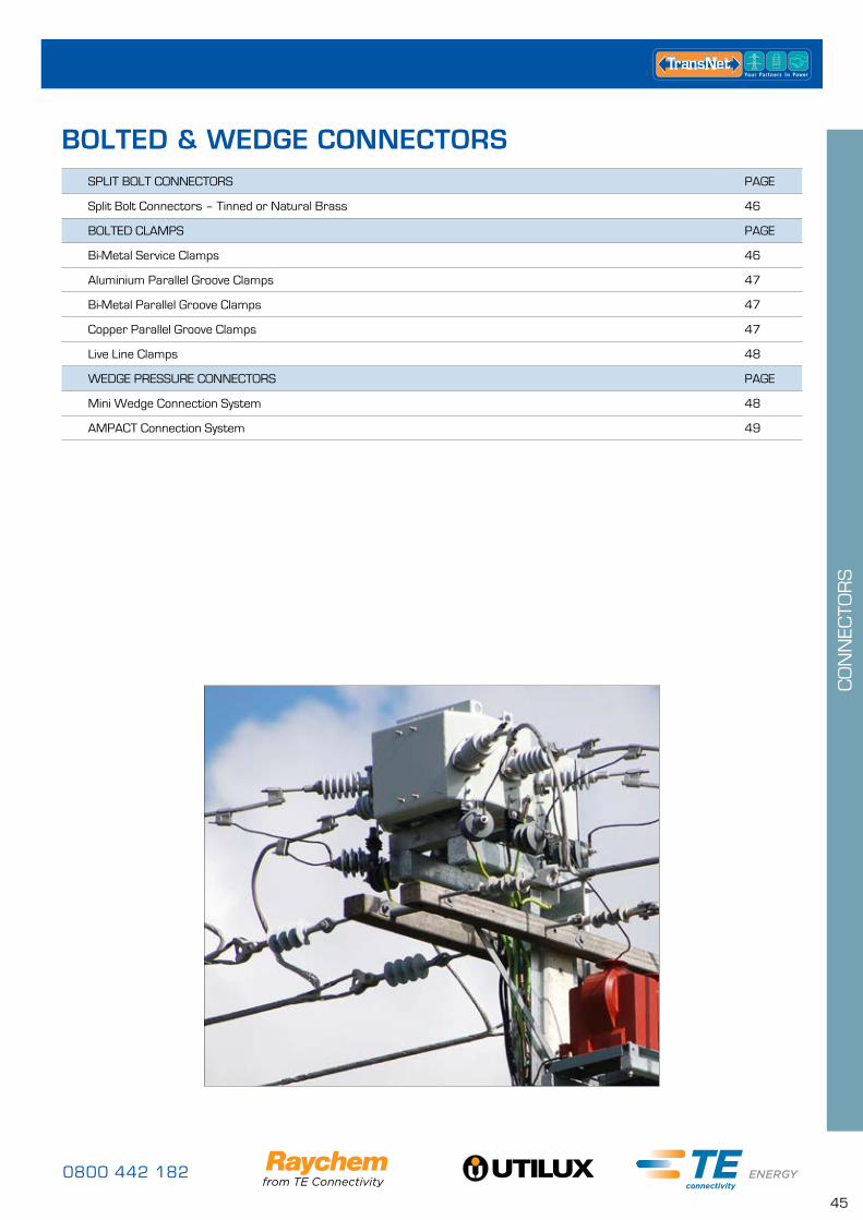
0800 442 182
45
CO
NN
ECTO
RS
SPLIT BOLT CONNECTORS PAGE
Split Bolt Connectors – Tinned or Natural Brass 46
BOLTED CLAMPS PAGE
Bi-Metal Service Clamps 46
Aluminium Parallel Groove Clamps 47
Bi-Metal Parallel Groove Clamps 47
Copper Parallel Groove Clamps 47
Live Line Clamps 48
WEDGE PRESSURE CONNECTORS PAGE
Mini Wedge Connection System 48
AMPACT Connection System 49
BOLTED & WEDGE CONNECTORS
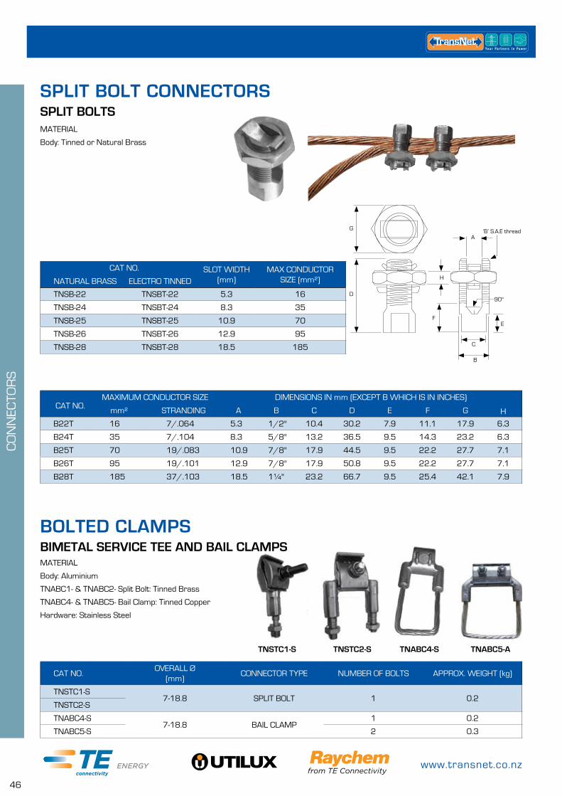
www.transnet.co.nz
46
CO
NN
ECTO
RS
CAT NO. SLOT WIDTH (mm)
MAX CONDUCTOR SIZE (mm²)NATURAL BRASS ELECTRO TINNED
TNSB-22 TNSBT-22 5.3 16
TNSB-24 TNSBT-24 8.3 35
TNSB-25 TNSBT-25 10.9 70
TNSB-26 TNSBT-26 12.9 95
TNSB-28 TNSBT-28 18.5 185
SPLIT BOLTSMATERIAL
Body: Tinned or Natural Brass
CAT NO.OVERALL Ø
(mm)CONNECTOR TYPE NUMBER OF BOLTS APPROX. WEIGHT (kg)
TNSTC1-S7-18.8 SPLIT BOLT 1 0.2
TNSTC2-S
TNABC4-S7-18.8 BAIL CLAMP
1 0.2
TNABC5-S 2 0.3
BIMETAL SERVICE TEE AND BAIL CLAMPSMATERIAL
Body: Aluminium
TNABC1- & TNABC2- Split Bolt: Tinned Brass
TNABC4- & TNABC5- Bail Clamp: Tinned Copper
Hardware: Stainless Steel
MAXIMUM CONDUCTOR SIZE DIMENSIONS IN mm (EXCEPT B WHICH IS IN INCHES) CAT NO. mm² STRANDING A B C D E F G H
B22T 16 7/.064 5.3 1/2'' 10.4 30.2 7.9 11.1 17.9 6.3
B24T 35 7/.104 8.3 5/8'' 13.2 36.5 9.5 14.3 23.2 6.3
B25T 70 19/.083 10.9 7/8'' 17.9 44.5 9.5 22.2 27.7 7.1
B26T 95 19/.101 12.9 7/8'' 17.9 50.8 9.5 22.2 27.7 7.1
B28T 185 37/.103 18.5 1¼'' 23.2 66.7 9.5 25.4 42.1 7.9
D
G
A‘B’ S.A.E thread
H
F
C
E
90°
B
SPLIT BOLT CONNECTORS
BOLTED CLAMPS
TNSTC1-S TNSTC2-S TNABC4-S TNABC5-A
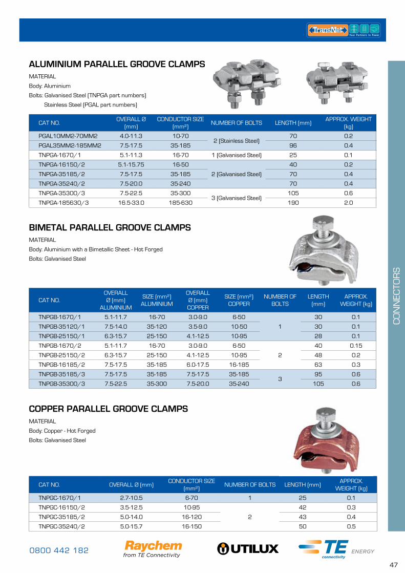
0800 442 182
47
CO
NN
ECTO
RS
CAT NO.OVERALL Ø
(mm)CONDUCTOR SIZE
(mm²)NUMBER OF BOLTS LENGTH (mm)
APPROX. WEIGHT (kg)
PGAL10MM2-70MM2 4.0-11.3 10-702 (Stainless Steel)
70 0.2
PGAL35MM2-185MM2 7.5-17.5 35-185 96 0.4
TNPGA-1670/1 5.1-11.3 16-70 1 (Galvanised Steel) 25 0.1
TNPGA-16150/2 5.1-15.75 16-50
2 (Galvanised Steel)
40 0.2
TNPGA-35185/2 7.5-17.5 35-185 70 0.4
TNPGA-35240/2 7.5-20.0 35-240 70 0.4
TNPGA-35300/3 7.5-22.5 35-3003 (Galvanised Steel)
105 0.6
TNPGA-185630/3 16.5-33.0 185-630 190 2.0
CAT NO. OVERALL Ø (mm)CONDUCTOR SIZE
(mm²)NUMBER OF BOLTS LENGTH (mm)
APPROX. WEIGHT (kg)
TNPGC-1670/1 2.7-10.5 6-70 1 25 0.1
TNPGC-16150/2 3.5-12.5 10-95
2
42 0.3
TNPGC-35185/2 5.0-14.0 16-120 43 0.4
TNPGC-35240/2 5.0-15.7 16-150 50 0.5
ALUMINIUM PARALLEL GROOVE CLAMPS
COPPER PARALLEL GROOVE CLAMPS
MATERIAL
Body: Aluminium
Bolts: Galvanised Steel (TNPGA part numbers)
Stainless Steel (PGAL part numbers)
MATERIAL
Body: Copper - Hot Forged
Bolts: Galvanised Steel
CAT NO.OVERALL Ø (mm)
ALUMINIUM
SIZE (mm²) ALUMINIUM
OVERALL Ø (mm) COPPER
SIZE (mm²)COPPER
NUMBER OF BOLTS
LENGTH (mm)
APPROX. WEIGHT (kg)
TNPGB-1670/1 5.1-11.7 16-70 3.0-9.0 6-50
1
30 0.1
TNPGB-35120/1 7.5-14.0 35-120 3.5-9.0 10-50 30 0.1
TNPGB-25150/1 6.3-15.7 25-150 4.1-12.5 10-95 28 0.1
TNPGB-1670/2 5.1-11.7 16-70 3.0-9.0 6-50
2
40 0.15
TNPGB-25150/2 6.3-15.7 25-150 4.1-12.5 10-95 48 0.2
TNPGB-16185/2 7.5-17.5 35-185 6.0-17.5 16-185 63 0.3
TNPGB-35185/3 7.5-17.5 35-185 7.5-17.5 35-1853
95 0.6
TNPGB-35300/3 7.5-22.5 35-300 7.5-20.0 35-240 105 0.6
BIMETAL PARALLEL GROOVE CLAMPSMATERIAL
Body: Aluminium with a Bimetallic Sheet - Hot Forged
Bolts: Galvanised Steel
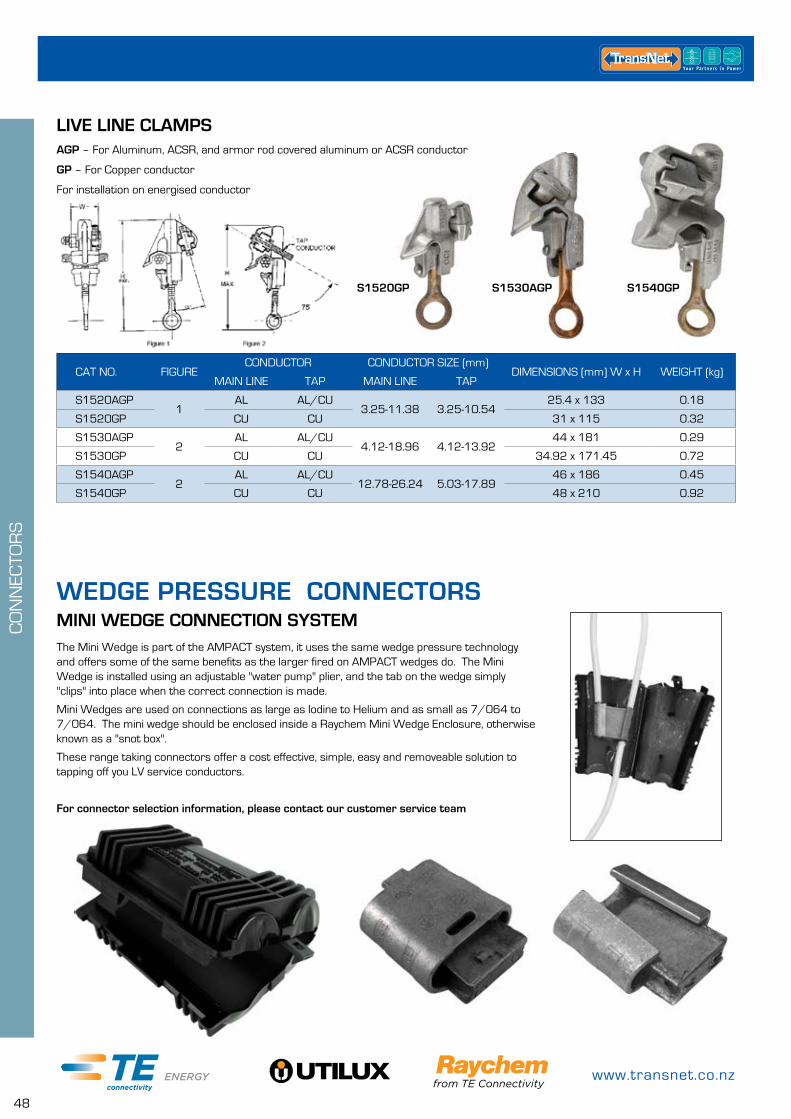
www.transnet.co.nz
48
CO
NN
ECTO
RS
LIVE LINE CLAMPSAGP – For Aluminum, ACSR, and armor rod covered aluminum or ACSR conductor
GP – For Copper conductor
For installation on energised conductor
CAT NO. FIGURECONDUCTOR CONDUCTOR SIZE (mm)
DIMENSIONS (mm) W x H WEIGHT (kg)MAIN LINE TAP MAIN LINE TAP
S1520AGP1
AL AL/CU3.25-11.38 3.25-10.54
25.4 x 133 0.18
S1520GP CU CU 31 x 115 0.32
S1530AGP2
AL AL/CU4.12-18.96 4.12-13.92
44 x 181 0.29
S1530GP CU CU 34.92 x 171.45 0.72
S1540AGP2
AL AL/CU12.78-26.24 5.03-17.89
46 x 186 0.45
S1540GP CU CU 48 x 210 0.92
S1530AGPS1520GP S1540GP
MINI WEDGE CONNECTION SYSTEMThe Mini Wedge is part of the AMPACT system, it uses the same wedge pressure technology and offers some of the same benefits as the larger fired on AMPACT wedges do. The Mini Wedge is installed using an adjustable "water pump" plier, and the tab on the wedge simply "clips" into place when the correct connection is made.
Mini Wedges are used on connections as large as Iodine to Helium and as small as 7/064 to 7/064. The mini wedge should be enclosed inside a Raychem Mini Wedge Enclosure, otherwise known as a "snot box".
These range taking connectors offer a cost effective, simple, easy and removeable solution to tapping off you LV service conductors.
For connector selection information, please contact our customer service team
WEDGE PRESSURE CONNECTORS
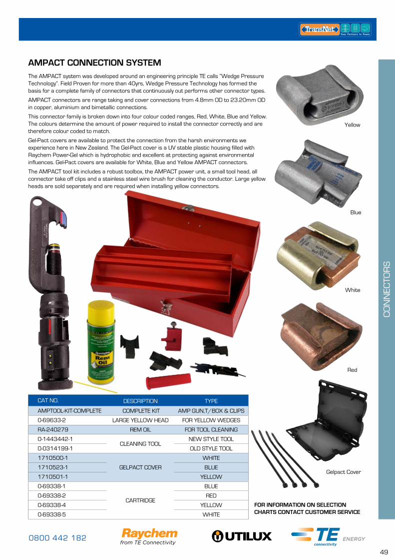
0800 442 182
49
CO
NN
ECTO
RS
AMPACT CONNECTION SYSTEMThe AMPACT system was developed around an engineering principle TE calls “Wedge Pressure Technology”. Field Proven for more than 40yrs, Wedge Pressure Technology has formed the basis for a complete family of connectors that continuously out performs other connector types.
AMPACT connectors are range taking and cover connections from 4.8mm OD to 23.20mm OD in copper, aluminium and bimetallic connections.
This connector family is broken down into four colour coded ranges, Red, White, Blue and Yellow. The colours determine the amount of power required to install the connector correctly and are therefore colour coded to match.
Gel-Pact covers are available to protect the connection from the harsh environments we experience here in New Zealand. The Gel-Pact cover is a UV stable plastic housing filled with Raychem Power-Gel which is hydrophobic and excellent at protecting against environmental influences. Gel-Pact covers are available for White, Blue and Yellow AMPACT connectors.
The AMPACT tool kit includes a robust toolbox, the AMPACT power unit, a small tool head, all connector take off clips and a stainless steel wire brush for cleaning the conductor. Large yellow heads are sold separately and are required when installing yellow connectors.
CAT NO. DESCRIPTION TYPE
AMPTOOL-KIT-COMPLETE COMPLETE KIT AMP GUN,T/BOX & CLIPS
0-69633-2 LARGE YELLOW HEAD FOR YELLOW WEDGES
RA-240279 REM OIL FOR TOOL CLEANING
0-1443442-1CLEANING TOOL
NEW STYLE TOOL
0-0314199-1 OLD STYLE TOOL
1710500-1
GELPACT COVER
WHITE
1710523-1 BLUE
1710501-1 YELLOW
0-69338-1
CARTRIDGE
BLUE
0-69338-2 RED
0-69338-4 YELLOW
0-69338-5 WHITE
Yellow
Blue
White
Red
Gelpact Cover
FOR INFORMATION ON SELECTION CHARTS CONTACT CUSTOMER SERVICE
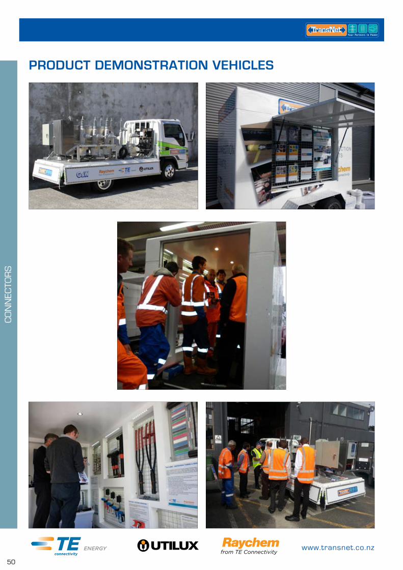
www.transnet.co.nz
50
PRODUCT DEMONSTRATION VEHICLES
CO
NN
ECTO
RS
0800 442 182
51
HEATSHRINK PRODUCTSMOULDED ACCESSORIES PAGE
Break Out Boots – Heatshrinkable Cable Breakouts 52
End Caps – Valved Heatshrinkable Cable End Caps 52
End Caps – Non-valved Heatshrinkable Cable End Caps 53
End Caps – Cold Applied Push On End Caps 53
HEATSHRINK TUBING PAGE
EZI Shrink – Thin Wall General Purpose Tubing Heatshrink 54
RNF100 – General Purpose Low Voltage Heatshrink 55
LV Heatshrink Multipacks 56
DWP/ATUM – ES1000/ES2000 – Thin Wall Adhesive Lined Heatshrink 56
MWTM – Medium Wall Adhesive Lined Heatshrink 58
WCSM – Heavy Wall Adhesive Lined Heatshrink 59
CRSM – Heatshrinkable Adhesive Lined Wrap-around Repair Sleeve 60
DCPT – Flexible Polyolefin Tubing 61
TFER – Heatshrinkable Teflon Tubing 61
FCSM – Flexible Medium-Wall Tubing 62
LVIT – Flexible Low Voltage Insulation Tubing 62
HEATSHRINK GLANDS PAGE
CFTS – Heatshrinkable Feedthrough Cable Glands 63
HEATSHRINK TAPE PAGE
LVBT – Low Voltage Busbar Tape 63
HVBT – High Voltage Busbar Tape 64
MEDIUM VOLTAGE BUSBAR INSULATION PAGE
BPTM – Medium Wall Busbar Insulation Tubing, 25kV 64
BBIT – Heavy Wall Busbar Insulation Tubing, 36kV 65
HVIS – High Voltage Insulation Sheets 65
HEATSHRINK PRODUCTS
HEA
TSH
RIN
K P
RO
DU
CTS
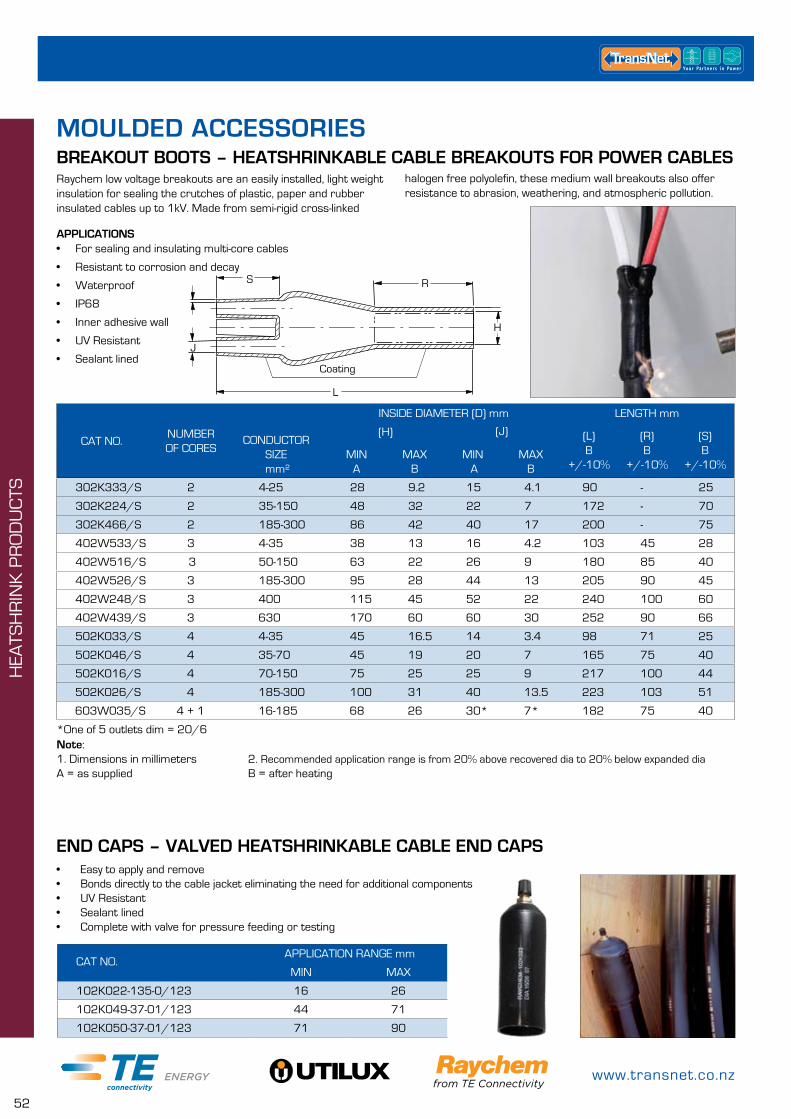
www.transnet.co.nz
52
CAT NO.APPLICATION RANGE mm
MIN MAX
102K022-135-0/123 16 26
102K049-37-01/123 44 71
102K050-37-01/123 71 90
Raychem low voltage breakouts are an easily installed, light weight insulation for sealing the crutches of plastic, paper and rubber insulated cables up to 1kV. Made from semi-rigid cross-linked
*One of 5 outlets dim = 20/6
BREAKOUT BOOTS – HEATSHRINKABLE CABLE BREAKOUTS FOR POWER CABLES
APPLICATIONS• For sealing and insulating multi-core cables
• Resistant to corrosion and decay
• Waterproof
• IP68
• Inner adhesive wall
• UV Resistant
• Sealant linedJ
L
S R
Coating
H
Note:1. Dimensions in millimeters 2. Recommended application range is from 20% above recovered dia to 20% below expanded diaA = as supplied B = after heating
halogen free polyolefin, these medium wall breakouts also offer resistance to abrasion, weathering, and atmospheric pollution.
CAT NO.NUMBER OF CORES
CONDUCTORSIZE mm²
INSIDE DIAMETER (D) mm LENGTH mm
(H) (J) (L)B
+/-10%
(R)B
+/-10%
(S)B
+/-10%MIN
AMAX
BMIN A
MAX B
302K333/S 2 4-25 28 9.2 15 4.1 90 - 25
302K224/S 2 35-150 48 32 22 7 172 - 70
302K466/S 2 185-300 86 42 40 17 200 - 75
402W533/S 3 4-35 38 13 16 4.2 103 45 28
402W516/S 3 50-150 63 22 26 9 180 85 40
402W526/S 3 185-300 95 28 44 13 205 90 45
402W248/S 3 400 115 45 52 22 240 100 60
402W439/S 3 630 170 60 60 30 252 90 66
502K033/S 4 4-35 45 16.5 14 3.4 98 71 25
502K046/S 4 35-70 45 19 20 7 165 75 40
502K016/S 4 70-150 75 25 25 9 217 100 44
502K026/S 4 185-300 100 31 40 13.5 223 103 51
603W035/S 4 + 1 16-185 68 26 30* 7* 182 75 40
END CAPS – VALVED HEATSHRINKABLE CABLE END CAPS• Easy to apply and remove• Bonds directly to the cable jacket eliminating the need for additional components • UV Resistant• Sealant lined• Complete with valve for pressure feeding or testing
HEA
TSH
RIN
K P
RO
DU
CTS
MOULDED ACCESSORIES
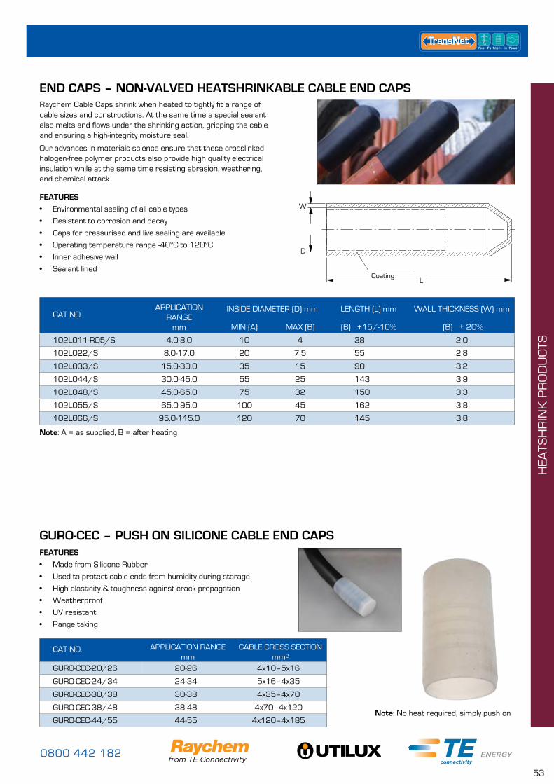
0800 442 182
53
END CAPS – NON-VALVED HEATSHRINKABLE CABLE END CAPSRaychem Cable Caps shrink when heated to tightly fit a range of cable sizes and constructions. At the same time a special sealant also melts and flows under the shrinking action, gripping the cable and ensuring a high-integrity moisture seal.
Our advances in materials science ensure that these crosslinked halogen-free polymer products also provide high quality electrical insulation while at the same time resisting abrasion, weathering, and chemical attack.
FEATURES
• Environmental sealing of all cable types
• Resistant to corrosion and decay
• Caps for pressurised and live sealing are available
• Operating temperature range -40°C to 120°C
• Inner adhesive wall
• Sealant lined
W
D
LCoating
CAT NO.APPLICATION
RANGEmm
INSIDE DIAMETER (D) mm LENGTH (L) mm WALL THICKNESS (W) mm
MIN (A) MAX (B) (B) +15/-10% (B) ± 20%
102L011-RO5/S 4.0-8.0 10 4 38 2.0
102L022/S 8.0-17.0 20 7.5 55 2.8
102L033/S 15.0-30.0 35 15 90 3.2
102L044/S 30.0-45.0 55 25 143 3.9
102L048/S 45.0-65.0 75 32 150 3.3
102L055/S 65.0-95.0 100 45 162 3.8
102L066/S 95.0-115.0 120 70 145 3.8
CAT NO. APPLICATION RANGEmm
CABLE CROSS SECTIONmm²
GURO-CEC-20/26 20-26 4x10–5x16
GURO-CEC-24/34 24-34 5x16–4x35
GURO-CEC-30/38 30-38 4x35–4x70
GURO-CEC-38/48 38-48 4x70–4x120
GURO-CEC-44/55 44-55 4x120–4x185
Note: A = as supplied, B = after heating
Note: No heat required, simply push on
GURO-CEC – PUSH ON SILICONE CABLE END CAPSFEATURES
• Made from Silicone Rubber
• Used to protect cable ends from humidity during storage
• High elasticity & toughness against crack propagation
• Weatherproof
• UV resistant
• Range taking
HEA
TSH
RIN
K P
RO
DU
CTS
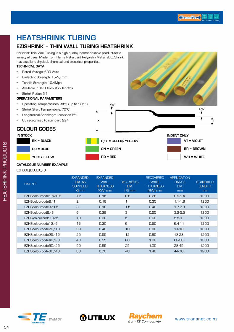
www.transnet.co.nz
54
EZISHRINK – THIN WALL TUBING HEATSHRINKEziShrink Thin Wall Tubing is a high quality, heatshrinkable product for a variety of uses. Made from Flame Retardant Polyolefin Material, EziShrink has excellent physical, chemical and electrical properties.TECHNICAL DATA
• Rated Voltage: 600 Volts
• Dielectric Strength: 15kV/mm
• Tensile Strength: 10.4Mpa
• Available in 1200mm stick lengths
• Shrink Ration 2:1OPERATIONAL PARAMETERS
• Operating Temperatures: -55°C up to 125°C
• Shrink Start Temperature: 70°C
• Longitudinal Shrinkage: Less than 8%
• UL recognised to standard 224
CAT NO.
EXPANDED DIA. AS
SUPPLIED(X) mm
EXPANDED WALL
THICKNESS (XW) mm
RECOVERED DIA.
(R) mm
RECOVERED WALL
THICKNESS (RW) mm
APPLICATION RANGE
DIA.mm
STANDARD LENGTH
mm
EZHScolourcode1.5/0.8 1.5 0.15 0.8 0.28 0.9-1.4 1200
EZHScolourcode2/1 2 0.18 1 0.35 1.1-1.8 1200
EZHScolourcode3/1.5 3 0.18 1.5 0.40 1.7-2.8 1200
EZHScolourcod6/3 6 0.28 3 0.55 3.2-5.5 1200
EZHS-colourcode10/5 10 0.30 5 0.60 5.5-9 1200
EZHScolourcode12/6 12 0.30 6 0.60 6.4-11 1200
EZHScolourcode20/10 20 0.40 10 0.80 11-18 1200
EZHScolourcode25/12 25 0.55 12 0.90 13-23 1200
EZHScolourcode40/20 40 0.55 20 1.00 22-36 1200
EZHScolourcode50/25 50 0.55 25 1.00 28-45 1200
EZHScolourcode80/40 80 0.70 40 1.46 44-70 1200
XW
X
RW
R
CATALOGUE NUMBER EXAMPLE
EZHSBU(BLUE)6/3
VT = VIOLET
COLOUR CODESIN STOCK
G/Y = GREEN/YELLOW BK = BLACK
INDENT ONLY
BU = BLUE
YO = YELLOW
GN = GREEN
RD = RED
BR = BROWN
WH = WHITE
HEATSHRINK TUBING
HEA
TSH
RIN
K P
RO
DU
CTS
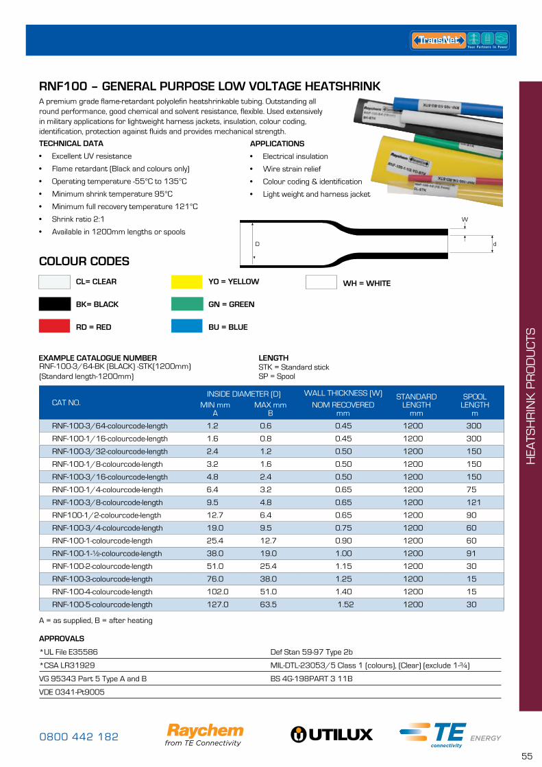
0800 442 182
55
RNF100 – GENERAL PURPOSE LOW VOLTAGE HEATSHRINK
EXAMPLE CATALOGUE NUMBERRNF-100-3/64-BK (BLACK) -STK(1200mm) (Standard length-1200mm)
A premium grade flame-retardant polyolefin heatshrinkable tubing. Outstanding all round performance, good chemical and solvent resistance, flexible. Used extensively in military applications for lightweight harness jackets, insulation, colour coding, identification, protection against fluids and provides mechanical strength.
CAT NO.INSIDE DIAMETER (D) WALL THICKNESS (W) STANDARD
LENGTHmm
SPOOLLENGTH
mMIN mm
AMAX mm
BNOM RECOVERED
mm
RNF-100-3/64-colourcode-length 1.2 0.6 0.45 1200 300
RNF-100-1/16-colourcode-length 1.6 0.8 0.45 1200 300
RNF-100-3/32-colourcode-length 2.4 1.2 0.50 1200 150
RNF-100-1/8-colourcode-length 3.2 1.6 0.50 1200 150
RNF-100-3/16-colourcode-length 4.8 2.4 0.50 1200 150
RNF-100-1/4-colourcode-length 6.4 3.2 0.65 1200 75
RNF-100-3/8-colourcode-length 9.5 4.8 0.65 1200 121
RNF100-1/2-colourcode-length 12.7 6.4 0.65 1200 90
RNF-100-3/4-colourcode-length 19.0 9.5 0.75 1200 60
RNF-100-1-colourcode-length 25.4 12.7 0.90 1200 60
RNF-100-1-½-colourcode-length 38.0 19.0 1.00 1200 91
RNF-100-2-colourcode-length 51.0 25.4 1.15 1200 30
RNF-100-3-colourcode-length 76.0 38.0 1.25 1200 15
RNF-100-4-colourcode-length 102.0 51.0 1.40 1200 15
RNF-100-5-colourcode-length 127.0 63.5 1.52 1200 30
APPLICATIONS
• Electrical insulation
• Wire strain relief
• Colour coding & identification
• Light weight and harness jacket
TECHNICAL DATA
• Excellent UV resistance
• Flame retardant (Black and colours only)
• Operating temperature -55°C to 135°C
• Minimum shrink temperature 95°C
• Minimum full recovery temperature 121°C
• Shrink ratio 2:1
• Available in 1200mm lengths or spools
LENGTHSTK = Standard stickSP = Spool
D
W
d
A = as supplied, B = after heating
CL= CLEAR
BK= BLACK
RD = RED
YO = YELLOW
GN = GREEN
BU = BLUE
WH = WHITE
APPROVALS
*UL File E35586 Def Stan 59-97 Type 2b
*CSA LR31929 MIL-DTL-23053/5 Class 1 (colours), (Clear) (exclude 1-¾)
VG 95343 Part 5 Type A and B BS 4G-198PART 3 11B
VDE 0341-Pt9005
COLOUR CODES
HEA
TSH
RIN
K P
RO
DU
CTS

www.transnet.co.nz
56
RAYCHEM LV HEATSHRINK MULTIPACKSRMP Packs• Contain various colours & sizes of Raychem RNF Heatshrink• Premium grade, Mil Spec compliant• Perfect for identification, colour coding, light harness jackets and light protection against abrasion.• AMS-DTL-23053/5 class 2 RDWP Packs• Premium grade polyolefin heatshrinkable tubing.• Good chemical and solvent resistance.• Adhesive lined for protection against moisture ingress• Flexible• AMS-DTL-23053/4 class 3 (Black only)
CAT NO. TYPE SIZES OD COLOURS
RMP-3SRNF – THIN WALL COLOURED
1/8”, 3/16”, 1/4”RED, WHITE, BLUE, BLACK, GREEN
RMP-3L 3/8”, 1/2”, 3/4”
RDWP-3STHIN WALL, ADHESIVE LINED
6, 7.4, 9, 10.8, 12mmBLACK, CLEAR
RDWP-3L 10.8, 12, 17.4, 19, 24mm
DWP/ATUM – ES1000/ES2000 – THIN WALL HEATSHRINKSemi-flexible, general purpose adhesive-lined, moisture proof heatshrinkable tubing, with high shrink ratio. Designed to provide moisture proof sealing to a wide range of substrates such as electrical wire splices, cable jackets, wire breakouts and electrical components.
APPLICATIONS
• Environmental sealing
• Cable insulation
• Connector insulation for control wiring
TECHNICAL DATA – DWP/ATUM
• Operating Temperature -55°C to 110°C
• Minimum shrink temperature 80°C
• Minimum full recovery temperature 110°C
• Shrink ratio 3:1
• Black (clear ATUM 40/13 only)
• Adhesive lined
TECHNICAL DATA – ES1000/ES2000
• Operating Temperature -40°C to 135°C
• Minimum shrink temperature 110°C
• Maximum full recovery temperature 135°C
• Shrink ratio 4:1
• ES1000 Clear, ES2000 Black
• Adhesive lined
APPROVALS
• UL E85381 (Black only)
• MIL-DTL-23053/4 Class 3 (Black only)
• 3:1 Shrink ratio only (excludes sizes 9/3,19/6)
• VG 95343 (clear 3:1 only)
• VDE 0341/Pt 9012 (clear 3:1 only)
HEA
TSH
RIN
K P
RO
DU
CTS
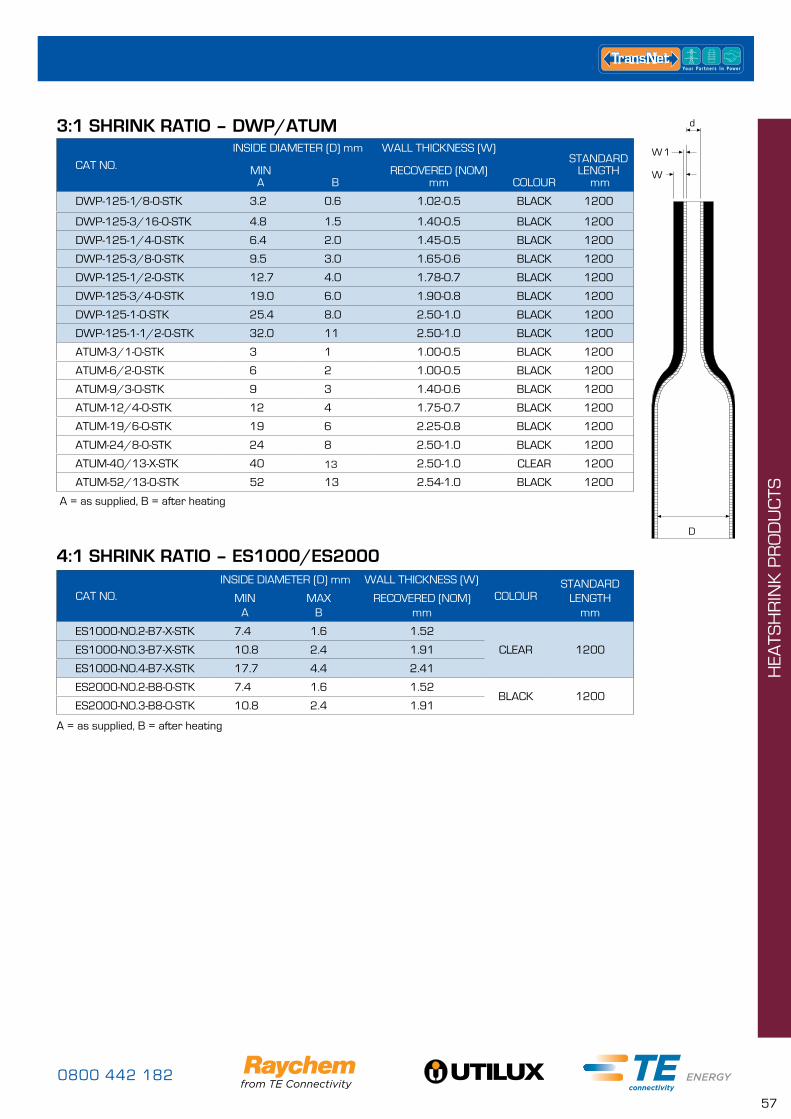
0800 442 182
57
3:1 SHRINK RATIO – DWP/ATUM
CAT NO.
INSIDE DIAMETER (D) mm WALL THICKNESS (W)
COLOUR
STANDARD LENGTH
mmRECOVERED (NOM)
mmMIN
A B
DWP-125-1/8-0-STK 3.2 0.6 1.02-0.5 BLACK 1200
DWP-125-3/16-0-STK 4.8 1.5 1.40-0.5 BLACK 1200
DWP-125-1/4-0-STK 6.4 2.0 1.45-0.5 BLACK 1200
DWP-125-3/8-0-STK 9.5 3.0 1.65-0.6 BLACK 1200
DWP-125-1/2-0-STK 12.7 4.0 1.78-0.7 BLACK 1200
DWP-125-3/4-0-STK 19.0 6.0 1.90-0.8 BLACK 1200
DWP-125-1-0-STK 25.4 8.0 2.50-1.0 BLACK 1200
DWP-125-1-1/2-0-STK 32.0 11 2.50-1.0 BLACK 1200
ATUM-3/1-O-STK 3 1 1.00-0.5 BLACK 1200
ATUM-6/2-0-STK 6 2 1.00-0.5 BLACK 1200
ATUM-9/3-O-STK 9 3 1.40-0.6 BLACK 1200
ATUM-12/4-0-STK 12 4 1.75-0.7 BLACK 1200
ATUM-19/6-O-STK 19 6 2.25-0.8 BLACK 1200
ATUM-24/8-0-STK 24 8 2.50-1.0 BLACK 1200
ATUM-40/13-X-STK 40 13 2.50-1.0 CLEAR 1200
ATUM-52/13-0-STK 52 13 2.54-1.0 BLACK 1200
D
d
W
1W
A = as supplied, B = after heating
4:1 SHRINK RATIO – ES1000/ES2000
CAT NO.INSIDE DIAMETER (D) mm WALL THICKNESS (W)
COLOURSTANDARD
LENGTHmm
MINA
MAXB
RECOVERED (NOM)mm
ES1000-NO.2-B7-X-STK 7.4 1.6 1.52
CLEAR 1200ES1000-NO.3-B7-X-STK 10.8 2.4 1.91
ES1000-NO.4-B7-X-STK 17.7 4.4 2.41
ES2000-NO.2-B8-0-STK 7.4 1.6 1.52BLACK 1200
ES2000-NO.3-B8-O-STK 10.8 2.4 1.91
A = as supplied, B = after heating
HEA
TSH
RIN
K P
RO
DU
CTS

www.transnet.co.nz
58
MWTM – MEDIUM WALL HEATSHRINK
CAT NO.APPLICATIONRANGE DIA.
mm
INSIDE DIAMETER mm (D) WALL THICKNESS mm (W) STANDARD LENGTH (L)
mm MIN MAX
A BMIN MAX A B
MWTM-10/3-1200/S 3.5-9.0 10 3 0.3 1.0 1200
MWTM-16/5-1200/S 5.5-14.5 16 5 0.3 1.4 1200
MWTM-25/8-1200/S 9.0-22.5 25 8 0.4 2.0 1200
MWTM-35/12-1200/S 13.0-31.5 35 12 0.4 2.0 1200
MWTM-50/16-1200/S 18-45.0 50 16 0.5 2.0 1200
MWTM-63/19-1200/S 21.0-57.0 63 19 0.6 2.4 1200
MWTM-75/22-1200/S 24.0-68.0 75 22 0.6 2.7 1200
MWTM-85/25-1200/S 28-77.0 85 25 0.6 2.8 1200
MWTM-95/29-1200/S 32.0-86.0 95 29 0.7 3.1 1200
MWTM-115/34-1200/S 37.0-104.0 115 34 0.7 3.1 1200
MWTM-140/42-1200/S 46.0-126.0 140 42 0.7 3.1 1200
MWTM-160/50-1200/S 55.0-144.0 160 50 0.7 3.2 1200
W
D
LSealant
TECHNICAL DATA
• Operating Temperature range -40°C to 120°C
• Shrink ratio 3:1
• Adhesive lined
• UV resistant
• Voltage class 1kV
• Sealant lined
• Halogen free
APPLICATIONS
• Fast cost effective way to waterproof joints
• Low voltage underground jointing and terminations
• Sealing of lugs and glands
• Resistant to chemicals, corrosion and decay
A = as supplied, B = after heating
Raychem MWTM tubing is fast and easily installed, and has proven its long term reliability in harsh climatic con ditions and polluted environments.
HEA
TSH
RIN
K P
RO
DU
CTS
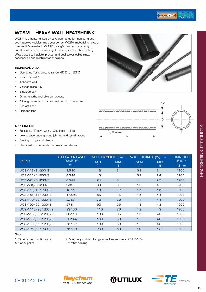
0800 442 182
59
WCSM – HEAVY WALL HEATSHRINKWCSM is a heatshrinkable heavy-wall tubing for insulating and sealing power cables and accessories. WCSM material is halogen free and UV resistant. WCSM tubing’s mechanical strength enables immediate back-filling of cable trenches after jointing.
Widely used to insulate, protect and seal power cable joints, accessories and electrical connections.
Sealant
D
W
L
CAT NO.APPLICATION RANGE
DIAMETERmm
INSIDE DIAMETER (D) mm WALL THICKNESS (W) mm STANDARDLENGTH
(L) mm MIN
AMAX
BNOM
AMAX
B
WCSM-12/3-1200/S 3.5-10 12 3 0.8 2 1200
WCSM-16/4-1200/S 4.5-14 16 4 0.9 2.4 1200
WCSM-24/6-1200/S 6.5-22 24 6 1 2.7 1200
WCSM-34/8-1200/S 9-31 33 8 1.3 4 1200
WCSM-48/12-1200/S 13-44 48 12 1.5 4.5 1200
WCSM-56/16-1200/S 17.5-50 56 16 1.5 4.4 1200
WCSM-70/20-1200/S 22-63 70 20 1.4 4.4 1200
WCSM-90/25-1200/S 27-81 90 25 1.3 4.3 1200
WCSM-110/30-1200/S 33-100 110 30 1.2 4.3 1200
WCSM-130/35-1200/S 38-118 130 35 1.2 4.3 1200
WCSM-160/50-1200/S 55-144 160 50 1 4.3 1200
WCSM-180/50-1200/S 55-162 180 50 1 4.3 1200
WCSM-250/65-2000/S 55-180 200 50 n.a. 4.3 2000
APPLICATIONS
• Fast cost effective way to waterproof joints
• Low voltage underground jointing and terminations
• Sealing of lugs and glands
• Resistant to chemicals, corrosion and decay
TECHNICAL DATA
• Operating Temperature range -40°C to 120°C
• Shrink ratio 4:1
• Adhesive wall
• Voltage class 1kV
• Black Colour
• Other lengths available on request.
• All lengths subject to standard cutting tolerances
• Sealant lined
• Halogen free
Note:
1. Dimensions in millimeters 2. Max. Longitudinal change after free recovery: +5%/-10% A = as supplied B = after heating
HEA
TSH
RIN
K P
RO
DU
CTS
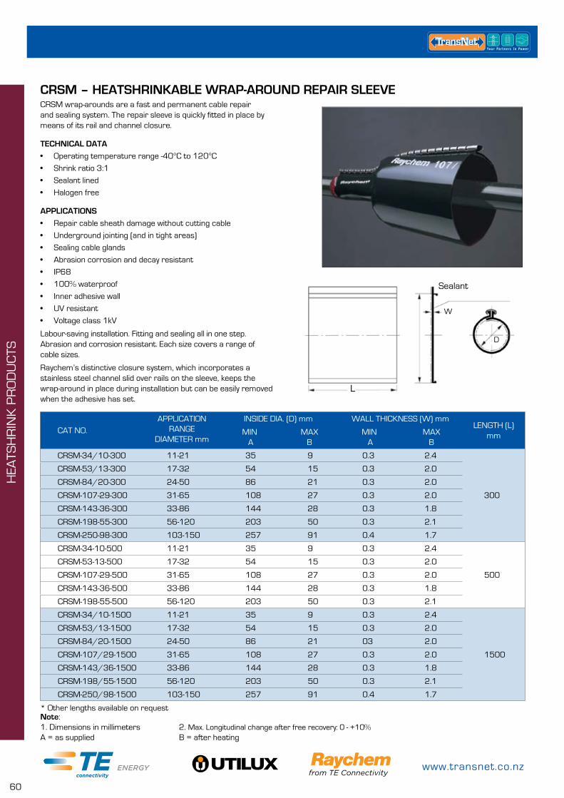
www.transnet.co.nz
60
CRSM – HEATSHRINKABLE WRAP-AROUND REPAIR SLEEVECRSM wrap-arounds are a fast and permanent cable repair and sealing system. The repair sleeve is quickly fitted in place by means of its rail and channel closure.
TECHNICAL DATA
• Operating temperature range -40°C to 120°C
• Shrink ratio 3:1
• Sealant lined
• Halogen free
APPLICATIONS
• Repair cable sheath damage without cutting cable
• Underground jointing (and in tight areas)
• Sealing cable glands
• Abrasion corrosion and decay resistant
• IP68
• 100% waterproof
• Inner adhesive wall
• UV resistant
• Voltage class 1kV
Labour-saving installation. Fitting and sealing all in one step. Abrasion and corrosion resistant. Each size covers a range of cable sizes.
Raychem’s distinctive closure system, which incorporates a stainless steel channel slid over rails on the sleeve, keeps the wrap-around in place during installation but can be easily removed when the adhesive has set.
CAT NO.APPLICATION
RANGEDIAMETER mm
INSIDE DIA. (D) mm WALL THICKNESS (W) mmLENGTH (L)
mmMIN A
MAXB
MIN A
MAXB
CRSM-34/10-300 11-21 35 9 0.3 2.4
300
CRSM-53/13-300 17-32 54 15 0.3 2.0
CRSM-84/20-300 24-50 86 21 0.3 2.0
CRSM-107-29-300 31-65 108 27 0.3 2.0
CRSM-143-36-300 33-86 144 28 0.3 1.8
CRSM-198-55-300 56-120 203 50 0.3 2.1
CRSM-250-98-300 103-150 257 91 0.4 1.7
CRSM-34-10-500 11-21 35 9 0.3 2.4
500
CRSM-53-13-500 17-32 54 15 0.3 2.0
CRSM-107-29-500 31-65 108 27 0.3 2.0
CRSM-143-36-500 33-86 144 28 0.3 1.8
CRSM-198-55-500 56-120 203 50 0.3 2.1
CRSM-34/10-1500 11-21 35 9 0.3 2.4
1500
CRSM-53/13-1500 17-32 54 15 0.3 2.0
CRSM-84/20-1500 24-50 86 21 03 2.0
CRSM-107/29-1500 31-65 108 27 0.3 2.0
CRSM-143/36-1500 33-86 144 28 0.3 1.8
CRSM-198/55-1500 56-120 203 50 0.3 2.1
CRSM-250/98-1500 103-150 257 91 0.4 1.7
Note:1. Dimensions in millimeters 2. Max. Longitudinal change after free recovery: 0 - +10%A = as supplied B = after heating
* Other lengths available on request
Sealant
L
D
W
HEA
TSH
RIN
K P
RO
DU
CTS
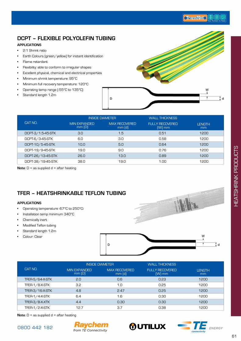
0800 442 182
61
DCPT – FLEXIBLE POLYOLEFIN TUBING
TFER – HEATSHRINKABLE TEFLON TUBING
APPLICATIONS
• 2:1 Shrink ratio
• Earth Colours (green/yellow) for instant identification
• Flame retardant
• Flexibility: able to conform to irregular shapes
• Excellent physical, chemical and electrical properties
• Minimum shrink temperature: 95°C
• Minimum full recovery temperature: 120°C
• Operating temp range (-55°C to 135°C)
• Standard length 1.2m
APPLICATIONS
• Operating temperature -67°C to 250°Ci
• Installation temp minimum 340°C
• Chemically inert
• Modified Teflon tubing
• Standard length 1.2m
• Colour: Clear
CAT NO.INSIDE DIAMETER WALL THICKNESS
LENGTHmm
MIN EXPANDED mm (D)
MAX RECOVERED mm (d)
FULLY RECOVERED (W) mm
DCPT-3/1.5-45-STK 3.0 1.5 0.51 1200
DCPT-6/3-45-STK 6.0 3.0 0.58 1200
DCPT-10/5-45-STK 10.0 5.0 0.64 1200
DCPT-19/9-45-STK 19.0 9.0 0.76 1200
DCPT-26/13-45-STK 26.0 13.0 0.89 1200
DCPT-38/19-45-STK 38.0 19.0 1.00 1200
Note: D = as supplied d = after heating
CAT NO.INSIDE DIAMETER WALL THICKNESS
LENGTHmm
MIN EXPANDED mm (D)
MAX RECOVERED mm (d)
FULLY RECOVERED
(W) mm
TFER-5/64-X-STK 2.0 0.6 0.23 1200
TFER-1/8-X-STK 3.2 1.0 0.25 1200
TFER-3/16-X-STK 4.8 2.47 0.25 1200
TFER-1/4-X-STK 6.4 1.6 0.30 1200
TFER-3/8-X-XTK 4.4 0.30 0.30 1200
TFER-1/2-X-STK 12.7 3.7 0.38 1200
Note: D = as supplied d = after heating
HEA
TSH
RIN
K P
RO
DU
CTS
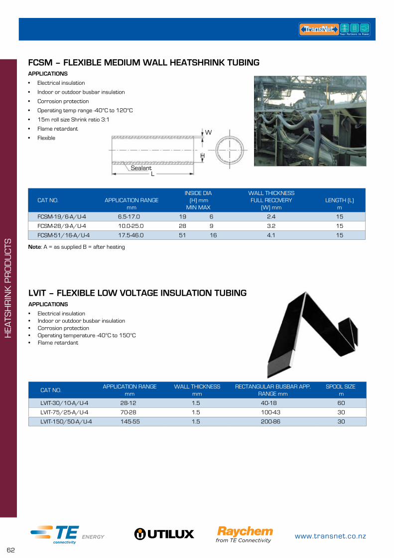
www.transnet.co.nz
62
FCSM – FLEXIBLE MEDIUM WALL HEATSHRINK TUBINGAPPLICATIONS
• Electrical insulation
• Indoor or outdoor busbar insulation
• Corrosion protection
• Operating temp range -40°C to 120°C
• 15m roll size Shrink ratio 3:1
• Flame retardant
• Flexible
CAT NO. APPLICATION RANGEmm
INSIDE DIA (H) mm
MIN MAX
WALL THICKNESSFULL RECOVERY
(W) mmLENGTH (L)
m
FCSM-19/6-A/U-4 6.5-17.0 19 6 2.4 15
FCSM-28/9-A/U-4 10.0-25.0 28 9 3.2 15
FCSM-51/16-A/U-4 17.5-46.0 51 16 4.1 15
Note: A = as supplied B = after heating
Sealant
W
L
H
LVIT – FLEXIBLE LOW VOLTAGE INSULATION TUBINGAPPLICATIONS
• Electrical insulation• Indoor or outdoor busbar insulation• Corrosion protection• Operating temperature -40°C to 150°C• Flame retardant
CAT NO.APPLICATION RANGE
mmWALL THICKNESS
mmRECTANGULAR BUSBAR APP.
RANGE mmSPOOL SIZE
m
LVIT-30/10-A/U-4 28-12 1.5 40-18 60
LVIT-75/25-A/U-4 70-28 1.5 100-43 30
LVIT-150/50-A/U-4 145-55 1.5 200-86 30
HEA
TSH
RIN
K P
RO
DU
CTS
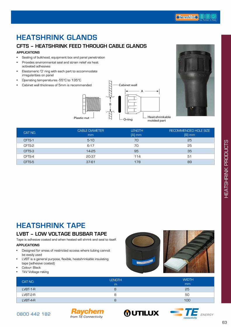
0800 442 182
63
LVBT – LOW VOLTAGE BUSBAR TAPE
APPLICATIONS
• Designed for areas of restricted access where tubing cannot be easily used
• LVBT is a general purpose, flexible, heatshrinkable insulating tape (adhesive coated)
• Colour: Black• 1kV Voltage rating
Tape is adhesive coated and when heated will shrink and seal to itself.
CAT NO. LENGTH
mWIDTH mm
LVBT-1-R 8 25
LVBT-2-R 8 50
LVBT-4-R 8 100
CFTS – HEATSHRINK FEED THROUGH CABLE GLANDS
CAT NO.CABLE DIAMETER
mmLENGTH(A) mm
RECOMMENDED HOLE SIZE(B) mm
CFTS-1 5-10 70 25
CFTS-2 6-17 70 25
CFTS-3 14-25 95 35
CFTS-4 20-37 114 51
CFTS-5 37-61 178 89
APPLICATIONS
• Sealing of bulkhead, equipment box and panel penetration
• Provides environmental seal and strain relief via heat activated adhesives
• Elastomeric ‘O’ ring with each part to accommodate irregularities on panel
• Operating temperatures -55°C to 135°C
• Cabinet wall thickness of 5mm is recommended
HEATSHRINK GLANDS
HEATSHRINK TAPE H
EATS
HR
INK
PR
OD
UC
TS
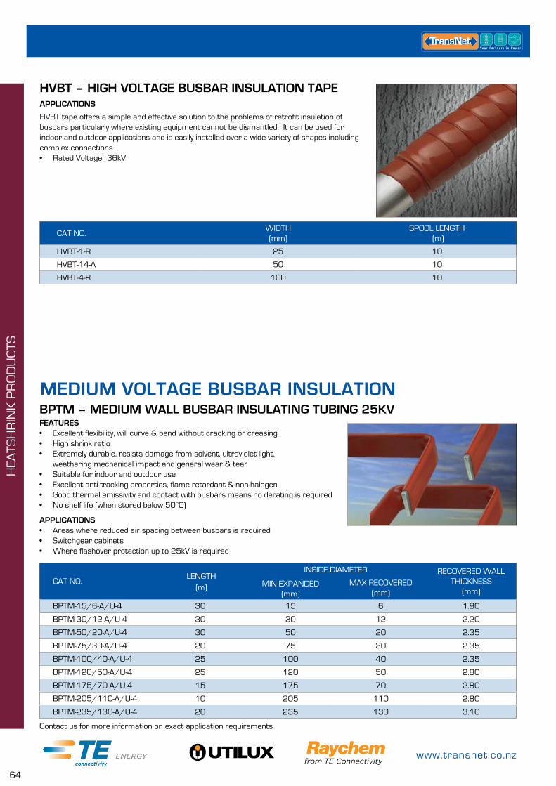
www.transnet.co.nz
64
BPTM – MEDIUM WALL BUSBAR INSULATING TUBING 25KV
APPLICATIONS• Areas where reduced air spacing between busbars is required• Switchgear cabinets• Where flashover protection up to 25kV is required
Contact us for more information on exact application requirements
FEATURES• Excellent flexibility, will curve & bend without cracking or creasing• High shrink ratio• Extremely durable, resists damage from solvent, ultraviolet light,
weathering mechanical impact and general wear & tear• Suitable for indoor and outdoor use• Excellent anti-tracking properties, flame retardant & non-halogen• Good thermal emissivity and contact with busbars means no derating is required• No shelf life (when stored below 50°C)
CAT NO. LENGTH
(m)
INSIDE DIAMETER RECOVERED WALL THICKNESS
(mm)MIN EXPANDED
(mm)MAX RECOVERED
(mm)
BPTM-15/6-A/U-4 30 15 6 1.90
BPTM-30/12-A/U-4 30 30 12 2.20
BPTM-50/20-A/U-4 30 50 20 2.35
BPTM-75/30-A/U-4 20 75 30 2.35
BPTM-100/40-A/U-4 25 100 40 2.35
BPTM-120/50-A/U-4 25 120 50 2.80
BPTM-175/70-A/U-4 15 175 70 2.80
BPTM-205/110-A/U-4 10 205 110 2.80
BPTM-235/130-A/U-4 20 235 130 3.10
MEDIUM VOLTAGE BUSBAR INSULATION
HVBT – HIGH VOLTAGE BUSBAR INSULATION TAPEAPPLICATIONS
HVBT tape offers a simple and effective solution to the problems of retrofit insulation of busbars particularly where existing equipment cannot be dismantled. It can be used for indoor and outdoor applications and is easily installed over a wide variety of shapes including complex connections.• Rated Voltage: 36kV
CAT NO.WIDTH(mm)
SPOOL LENGTH (m)
HVBT-1-R 25 10
HVBT-14-A 50 10
HVBT-4-R 100 10
HEA
TSH
RIN
K P
RO
DU
CTS
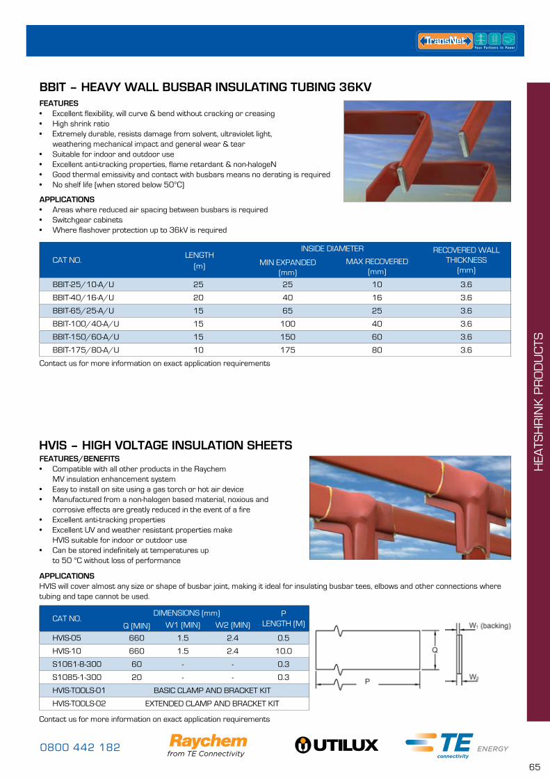
0800 442 182
65
BBIT – HEAVY WALL BUSBAR INSULATING TUBING 36KV
APPLICATIONS• Areas where reduced air spacing between busbars is required• Switchgear cabinets• Where flashover protection up to 36kV is required
FEATURES• Excellent flexibility, will curve & bend without cracking or creasing• High shrink ratio• Extremely durable, resists damage from solvent, ultraviolet light,
weathering mechanical impact and general wear & tear• Suitable for indoor and outdoor use• Excellent anti-tracking properties, flame retardant & non-halogeN• Good thermal emissivity and contact with busbars means no derating is required• No shelf life (when stored below 50°C)
CAT NO. LENGTH
(m)
INSIDE DIAMETER RECOVERED WALL THICKNESS
(mm)MIN EXPANDED
(mm)MAX RECOVERED
(mm)
BBIT-25/10-A/U 25 25 10 3.6
BBIT-40/16-A/U 20 40 16 3.6
BBIT-65/25-A/U 15 65 25 3.6
BBIT-100/40-A/U 15 100 40 3.6
BBIT-150/60-A/U 15 150 60 3.6
BBIT-175/80-A/U 10 175 80 3.6
Contact us for more information on exact application requirements
HVIS – HIGH VOLTAGE INSULATION SHEETS
APPLICATIONSHVIS will cover almost any size or shape of busbar joint, making it ideal for insulating busbar tees, elbows and other connections where tubing and tape cannot be used.
FEATURES/BENEFITS• Compatible with all other products in the Raychem
MV insulation enhancement system• Easy to install on site using a gas torch or hot air device• Manufactured from a non-halogen based material, noxious and
corrosive effects are greatly reduced in the event of a fire• Excellent anti-tracking properties• Excellent UV and weather resistant properties make
HVIS suitable for indoor or outdoor use• Can be stored indefinitely at temperatures up
to 50 °C without loss of performance
CAT NO.DIMENSIONS (mm) P
LENGTH (M)Q (MIN) W1 (MIN) W2 (MIN)
HVIS-05 660 1.5 2.4 0.5
HVIS-10 660 1.5 2.4 10.0
S1061-8-300 60 - - 0.3
S1085-1-300 20 - - 0.3
HVIS-TOOLS-01 BASIC CLAMP AND BRACKET KIT
HVIS-TOOLS-02 EXTENDED CLAMP AND BRACKET KIT
Contact us for more information on exact application requirements
HEA
TSH
RIN
K P
RO
DU
CTS
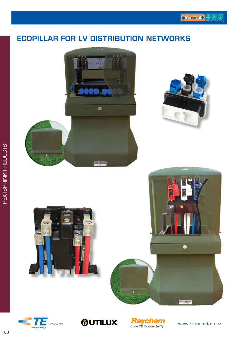
www.transnet.co.nz
66
HEA
TSH
RIN
K P
RO
DU
CTS
ECOPILLAR FOR LV DISTRIBUTION NETWORKS
0800 442 182
67
LV C
AB
LE A
CC
ESS
OR
IES
LV CABLE ACCESSORIESGEL FILLED PRODUCTS PAGE
GelPort 68
RayGel Enclosures & Joint Kits 68
Cable Glands for RayGel Enclosures 69
GHFC Gel Enclosures 69
Mini Wedge Gel Enclosures 70
GelCap SL 70
GelWrap 70
GUROSIL – Gel Filled Junction Box Including Terminal Strip 71
RESIN FILLED JOINT KITS PAGE
Guro Resin Joint Kits 72
Guroflex Resin 72
PXE – LV Resin Straight Joints 73
ESJ-R – LV Resin Straight Joints Includes Mechanical Connectors 73
TSJ – LV Resin Straight Joints 74
TBJ – LV Resin Branch Joints 74
Resin – RAPID 4300 75
XLPE LV INLINE HEATSHRINK JOINTS UP TO 1KV PAGE
LVJM – LV Inline Joints for XLPE Cables, Includes Mechanical Connectors 76
LJSM – LV Inline Joints for XLPE Cables, Includes Mechanical Connectors 76
ESJ – LV Inline Joints for XLPE Cables, Includes Mechanical Connectors 77
LVK & TJ – LV Inline Joints for TPS cable 77
CRSM-CT & CRSM-CT-M – LV 1 Core Branch Joints (with and without mechanical connectors) 77
EPKJ – LV Inline Joints for Control Cables 78
EPKJ – LV Inline Joints Paper Insulated Cables 78
EPKJ – LV Inline Transition Joints (Armoured Plastic Cables) 78
LJTM – LV Inline Transition Joints 78
LVTM – LV Termination Kits, Includes Mechanical Connectors 79
LVTE – LV End of Run Joints 79
LESK – LV Live End Seal Kits 79
ROLL ON JOINT SYSTEM PAGE
RVS – Rayvolve Roll On Jointing Sleeves 80
ACCESSORIES PAGE
Earth Braid 80
Roll Springs 81
LV LINK BOX & PILLAR KITS PAGE
Tappat Link Box 81
Tappat 2 way Link Pillar 82
Tappat 3 way Link Pillar 82
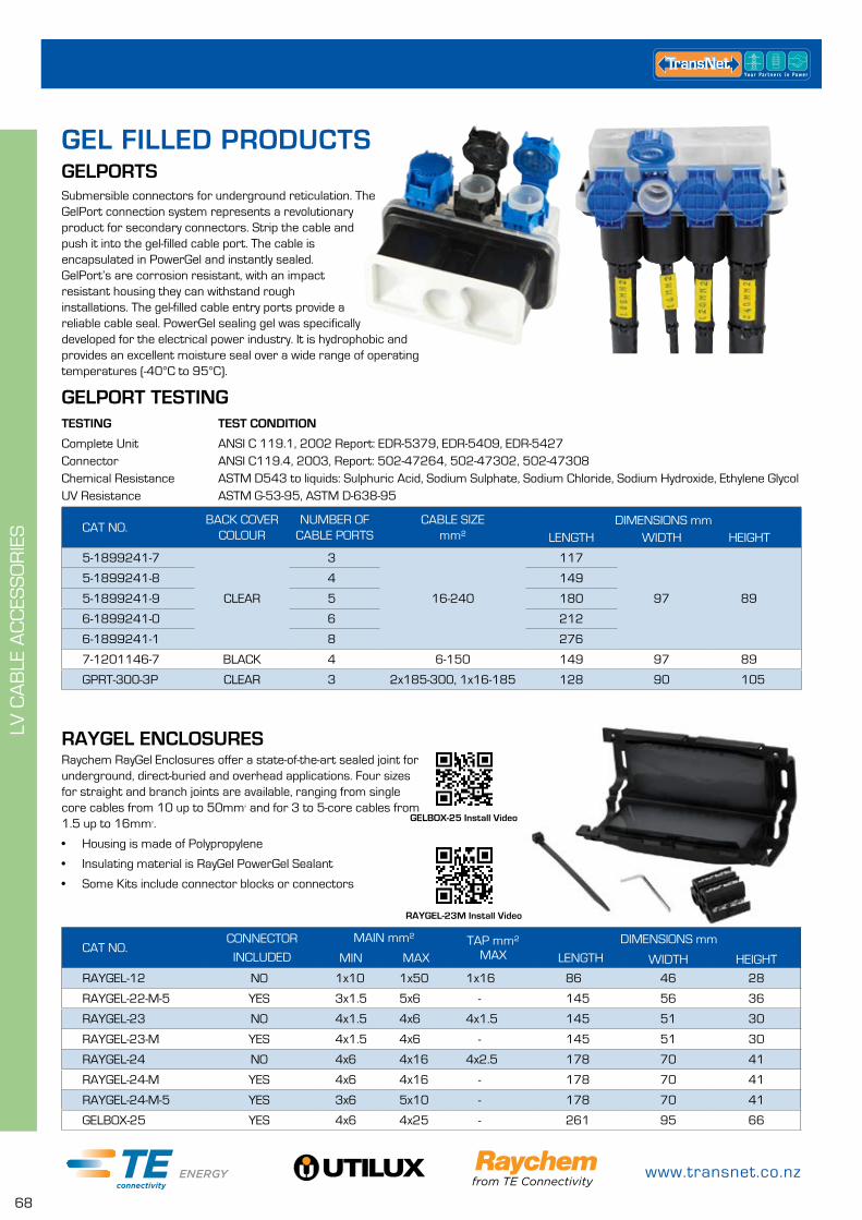
www.transnet.co.nz
68
LV C
AB
LE A
CC
ESS
OR
IES CAT NO.
BACK COVER COLOUR
NUMBER OF CABLE PORTS
CABLE SIZEmm²
DIMENSIONS mmLENGTH WIDTH HEIGHT
5-1899241-7
CLEAR
3
16-240
117
97 89
5-1899241-8 4 149
5-1899241-9 5 180
6-1899241-0 6 212
6-1899241-1 8 276
7-1201146-7 BLACK 4 6-150 149 97 89
GPRT-300-3P CLEAR 3 2x185-300, 1x16-185 128 90 105
GELPORTS
GELPORT TESTINGTESTING TEST CONDITION
Complete Unit ANSI C 119.1, 2002 Report: EDR-5379, EDR-5409, EDR-5427Connector ANSI C119.4, 2003, Report: 502-47264, 502-47302, 502-47308Chemical Resistance ASTM D543 to liquids: Sulphuric Acid, Sodium Sulphate, Sodium Chloride, Sodium Hydroxide, Ethylene GlycolUV Resistance ASTM G-53-95, ASTM D-638-95
Submersible connectors for underground reticulation. The GelPort connection system represents a revolutionary product for secondary connectors. Strip the cable and push it into the gel-filled cable port. The cable is encapsulated in PowerGel and instantly sealed. GelPort’s are corrosion resistant, with an impact resistant housing they can withstand rough installations. The gel-filled cable entry ports provide a reliable cable seal. PowerGel sealing gel was specifically developed for the electrical power industry. It is hydrophobic and provides an excellent moisture seal over a wide range of operating temperatures (-40°C to 95°C).
RAYGEL ENCLOSURESRaychem RayGel Enclosures offer a state-of-the-art sealed joint for underground, direct-buried and overhead applications. Four sizes for straight and branch joints are available, ranging from single core cables from 10 up to 50mm² and for 3 to 5-core cables from 1.5 up to 16mm².
• Housing is made of Polypropylene
• Insulating material is RayGel PowerGel Sealant
• Some Kits include connector blocks or connectors
CAT NO.CONNECTOR
INCLUDED
MAIN mm² TAP mm²
MAXDIMENSIONS mm
MIN MAX LENGTH WIDTH HEIGHT
RAYGEL-12 NO 1x10 1x50 1x16 86 46 28
RAYGEL-22-M-5 YES 3x1.5 5x6 - 145 56 36
RAYGEL-23 NO 4x1.5 4x6 4x1.5 145 51 30
RAYGEL-23-M YES 4x1.5 4x6 - 145 51 30
RAYGEL-24 NO 4x6 4x16 4x2.5 178 70 41
RAYGEL-24-M YES 4x6 4x16 - 178 70 41
RAYGEL-24-M-5 YES 3x6 5x10 - 178 70 41
GELBOX-25 YES 4x6 4x25 - 261 95 66
RAYGEL-23M Install Video
GELBOX-25 Install Video
GEL FILLED PRODUCTS
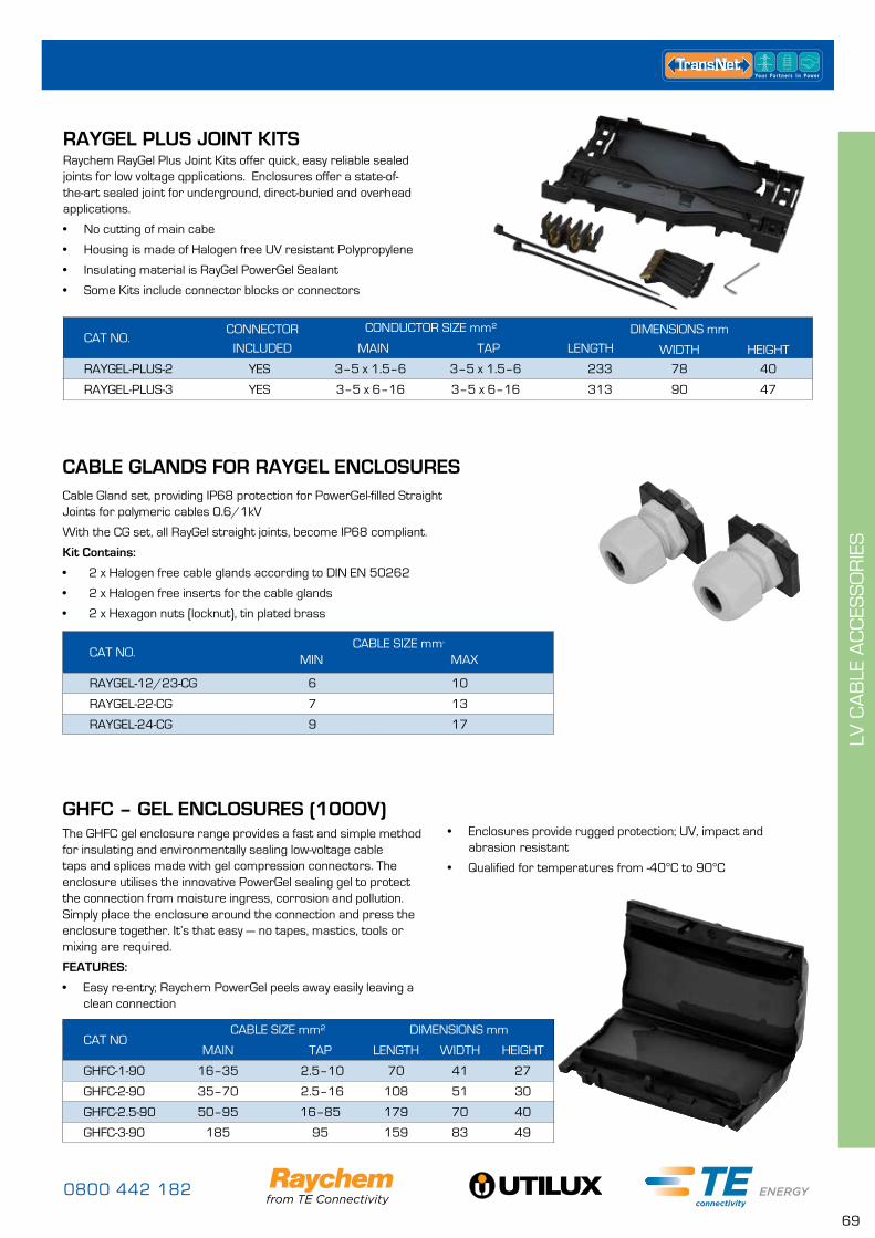
0800 442 182
69
LV C
AB
LE A
CC
ESS
OR
IES
GHFC – GEL ENCLOSURES (1000V)The GHFC gel enclosure range provides a fast and simple method for insulating and environmentally sealing low-voltage cable taps and splices made with gel compression connectors. The enclosure utilises the innovative PowerGel sealing gel to protect the connection from moisture ingress, corrosion and pollution. Simply place the enclosure around the connection and press the enclosure together. It’s that easy — no tapes, mastics, tools or mixing are required.
FEATURES:
• Easy re-entry; Raychem PowerGel peels away easily leaving a clean connection
• Ideal for street lighting and service applicationsCAT NO
CABLE SIZE mm² DIMENSIONS mm
MAIN TAP LENGTH WIDTH HEIGHT
GHFC-1-90 16–35 2.5–10 70 41 27
GHFC-2-90 35–70 2.5–16 108 51 30
GHFC-2.5-90 50–95 16–85 179 70 40
GHFC-3-90 185 95 159 83 49
CAT NO.CABLE SIZE mm²
MIN MAX
RAYGEL-12/23-CG 6 10
RAYGEL-22-CG 7 13
RAYGEL-24-CG 9 17
CABLE GLANDS FOR RAYGEL ENCLOSURESCable Gland set, providing IP68 protection for PowerGel-filled Straight Joints for polymeric cables 0.6/1kV
With the CG set, all RayGel straight joints, become IP68 compliant.
Kit Contains:
• 2 x Halogen free cable glands according to DIN EN 50262
• 2 x Halogen free inserts for the cable glands
• 2 x Hexagon nuts (locknut), tin plated brass
RAYGEL PLUS JOINT KITSRaychem RayGel Plus Joint Kits offer quick, easy reliable sealed joints for low voltage qpplications. Enclosures offer a state-of-the-art sealed joint for underground, direct-buried and overhead applications.
• No cutting of main cabe
• Housing is made of Halogen free UV resistant Polypropylene
• Insulating material is RayGel PowerGel Sealant
• Some Kits include connector blocks or connectors
CAT NO.CONNECTOR
INCLUDED
CONDUCTOR SIZE mm² DIMENSIONS mm
MAIN TAP LENGTH WIDTH HEIGHT
RAYGEL-PLUS-2 YES 3–5 x 1.5–6 3–5 x 1.5–6 233 78 40
RAYGEL-PLUS-3 YES 3–5 x 6–16 3–5 x 6–16 313 90 47
• Enclosures provide rugged protection; UV, impact and abrasion resistant
• Qualified for temperatures from -40°C to 90°C
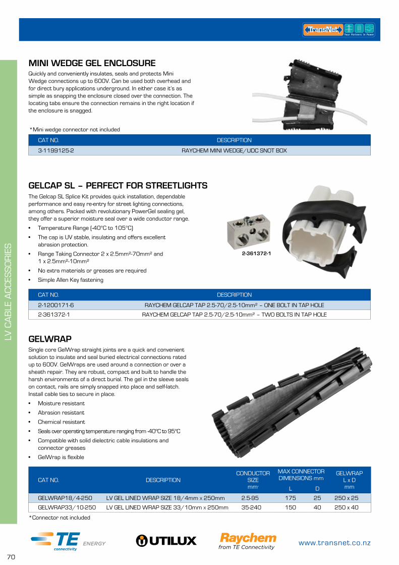
www.transnet.co.nz
70
LV C
AB
LE A
CC
ESS
OR
IES
GELWRAPSingle core GelWrap straight joints are a quick and convenient solution to insulate and seal buried electrical connections rated up to 600V. GelWraps are used around a connection or over a sheath repair. They are robust, compact and built to handle the harsh environments of a direct burial. The gel in the sleeve seals on contact, rails are simply snapped into place and self-latch. Install cable ties to secure in place.
• Moisture resistant
• Abrasion resistant
• Chemical resistant
• Seals over operating temperature ranging from -40°C to 95°C
• Compatible with solid dielectric cable insulations and connector greases
• GelWrap is flexible
CAT NO. DESCRIPTIONCONDUCTOR
SIZEmm²
MAX CONNECTOR DIMENSIONS mm
GELWRAP L x DmmL D
GELWRAP18/4-250 LV GEL LINED WRAP SIZE 18/4mm x 250mm 2.5-95 175 25 250 x 25
GELWRAP33/10-250 LV GEL LINED WRAP SIZE 33/10mm x 250mm 35-240 150 40 250 x 40
CAT NO. DESCRIPTION
2-1200171-6 RAYCHEM GELCAP TAP 2.5-70/2.5-10mm² – ONE BOLT IN TAP HOLE
2-361372-1 RAYCHEM GELCAP TAP 2.5-70/2.5-10mm² – TWO BOLTS IN TAP HOLE
GELCAP SL – PERFECT FOR STREETLIGHTSThe Gelcap SL Splice Kit provides quick installation, dependable performance and easy re-entry for street lighting connections, among others. Packed with revolutionary PowerGel sealing gel, they offer a superior moisture seal over a wide conductor range.
• Temperature Range (-40°C to 105°C)
• The cap is UV stable, insulating and offers excellent abrasion protection.
• Range Taking Connector 2 x 2.5mm²-70mm² and 1 x 2.5mm²-10mm²
• No extra materials or greases are required
• Simple Allen Key fastening
*Connector not included
MINI WEDGE GEL ENCLOSURE
CAT NO. DESCRIPTION
3-1199125-2 RAYCHEM MINI WEDGE/UDC SNOT BOX
Quickly and conveniently insulates, seals and protects Mini Wedge connections up to 600V. Can be used both overhead and for direct bury applications underground. In either case it’s as simple as snapping the enclosure closed over the connection. The locating tabs ensure the connection remains in the right location if the enclosure is snagged.
*Mini wedge connector not included
2-361372-1
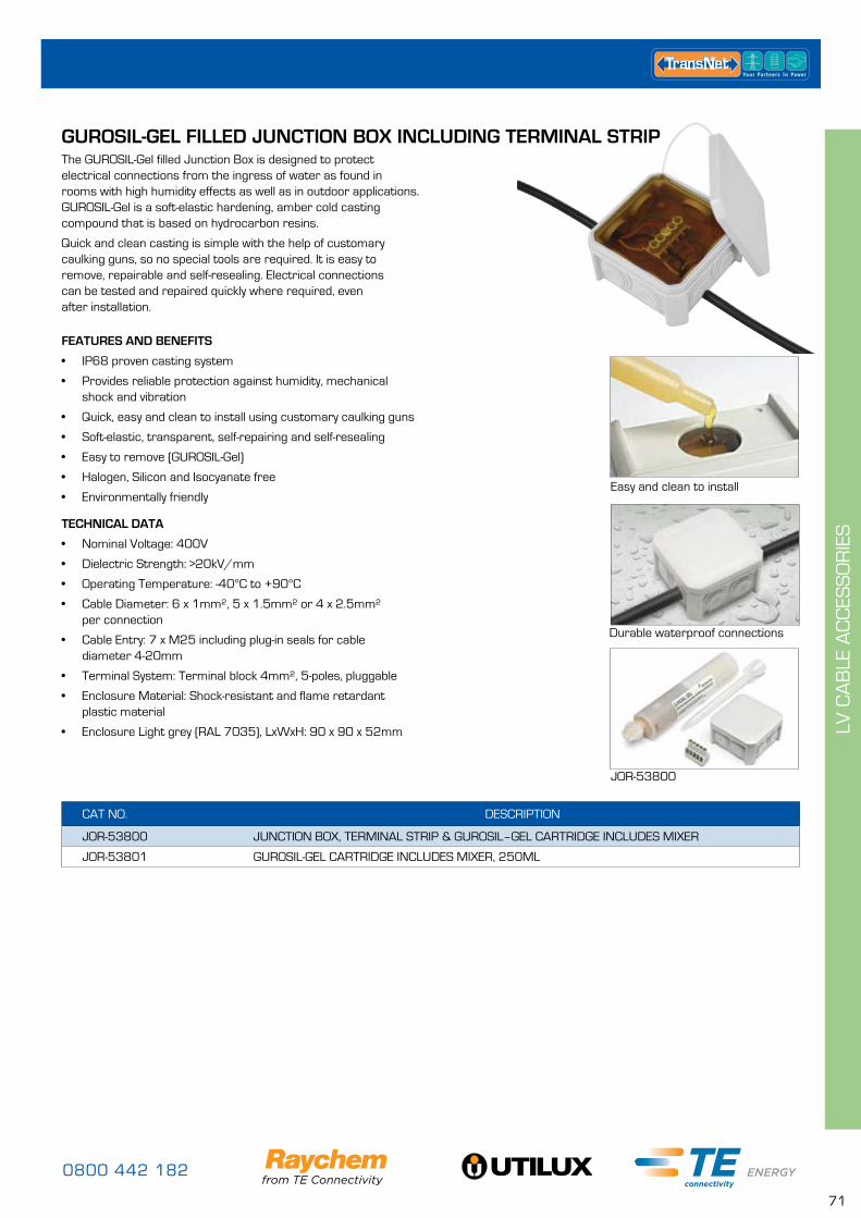
0800 442 182
71
LV C
AB
LE A
CC
ESS
OR
IES
GUROSIL-GEL FILLED JUNCTION BOX INCLUDING TERMINAL STRIPThe GUROSIL-Gel filled Junction Box is designed to protect electrical connections from the ingress of water as found in rooms with high humidity effects as well as in outdoor applications. GUROSIL-Gel is a soft-elastic hardening, amber cold casting compound that is based on hydrocarbon resins.
Quick and clean casting is simple with the help of customary caulking guns, so no special tools are required. It is easy to remove, repairable and self-resealing. Electrical connections can be tested and repaired quickly where required, even after installation.
Easy and clean to install
Durable waterproof connections
JOR-53800
FEATURES AND BENEFITS
• IP68 proven casting system
• Provides reliable protection against humidity, mechanical shock and vibration
• Quick, easy and clean to install using customary caulking guns
• Soft-elastic, transparent, self-repairing and self-resealing
• Easy to remove (GUROSIL-Gel)
• Halogen, Silicon and Isocyanate free
• Environmentally friendly
TECHNICAL DATA
• Nominal Voltage: 400V
• Dielectric Strength: >20kV/mm
• Operating Temperature: -40°C to +90°C
• Cable Diameter: 6 x 1mm², 5 x 1.5mm² or 4 x 2.5mm² per connection
• Cable Entry: 7 x M25 including plug-in seals for cable diameter 4-20mm
• Terminal System: Terminal block 4mm², 5-poles, pluggable
• Enclosure Material: Shock-resistant and flame retardant plastic material
• Enclosure Light grey (RAL 7035), LxWxH: 90 x 90 x 52mm
CAT NO. DESCRIPTION
JOR-53800 JUNCTION BOX, TERMINAL STRIP & GUROSIL–GEL CARTRIDGE INCLUDES MIXER
JOR-53801 GUROSIL-GEL CARTRIDGE INCLUDES MIXER, 250ML
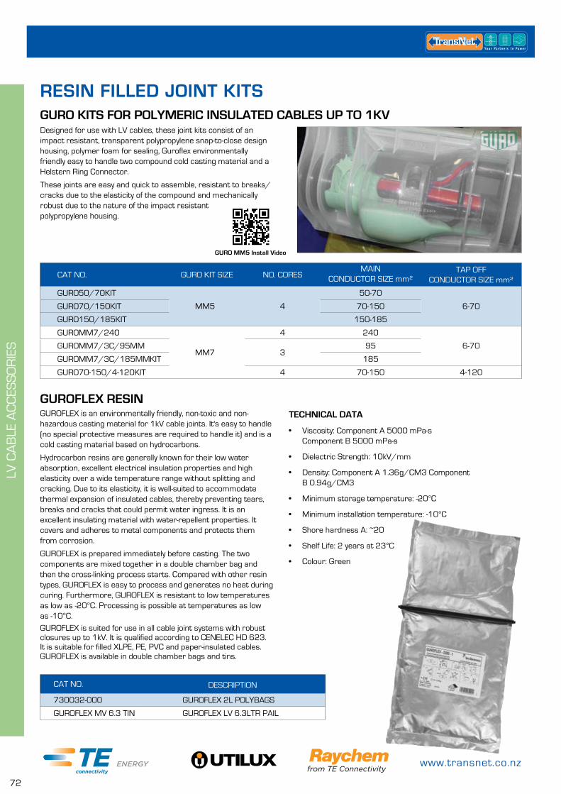
www.transnet.co.nz
72
LV C
AB
LE A
CC
ESS
OR
IES
CAT NO. GURO KIT SIZE NO. CORESMAIN
CONDUCTOR SIZE mm²TAP OFF
CONDUCTOR SIZE mm²
GURO50/70KIT
MM5 4
50-70
6-70GURO70/150KIT 70-150
GURO150/185KIT 150-185
GUROMM7/240
MM7
4 240
6-70GUROMM7/3C/95MM3
95
GUROMM7/3C/185MMKIT 185
GURO70-150/4-120KIT 4 70-150 4-120
CAT NO. DESCRIPTION
730032-000 GUROFLEX 2L POLYBAGS
GUROFLEX MV 6.3 TIN GUROFLEX LV 6.3LTR PAIL
RESIN FILLED JOINT KITSGURO KITS FOR POLYMERIC INSULATED CABLES UP TO 1KV
GUROFLEX RESINTECHNICAL DATA
• Viscosity: Component A 5000 mPa-s Component B 5000 mPa-s
• Dielectric Strength: 10kV/mm
• Density: Component A 1.36g/CM3 Component B 0.94g/CM3
• Minimum storage temperature: -20°C
• Minimum installation temperature: -10°C
• Shore hardness A: ~20
• Shelf Life: 2 years at 23°C
• Colour: Green
GUROFLEX is an environmentally friendly, non-toxic and non-hazardous casting material for 1kV cable joints. It's easy to handle (no special protective measures are required to handle it) and is a cold casting material based on hydrocarbons.
Hydrocarbon resins are generally known for their low water absorption, excellent electrical insulation properties and high elasticity over a wide temperature range without splitting and cracking. Due to its elasticity, it is well-suited to accommodate thermal expansion of insulated cables, thereby preventing tears, breaks and cracks that could permit water ingress. It is an excellent insulating material with water-repellent properties. It covers and adheres to metal components and protects them from corrosion.
GUROFLEX is prepared immediately before casting. The two components are mixed together in a double chamber bag and then the cross-linking process starts. Compared with other resin types, GUROFLEX is easy to process and generates no heat during curing. Furthermore, GUROFLEX is resistant to low temperatures as low as -20°C. Processing is possible at temperatures as low as -10°C.
GUROFLEX is suited for use in all cable joint systems with robust closures up to 1kV. It is qualified according to CENELEC HD 623. It is suitable for filled XLPE, PE, PVC and paper-insulated cables. GUROFLEX is available in double chamber bags and tins.
Designed for use with LV cables, these joint kits consist of an impact resistant, transparent polypropylene snap-to-close design housing, polymer foam for sealing, Guroflex environmentally friendly easy to handle two compound cold casting material and a Helstern Ring Connector.
These joints are easy and quick to assemble, resistant to breaks/cracks due to the elasticity of the compound and mechanically robust due to the nature of the impact resistant polypropylene housing.
GURO MM5 Install Video
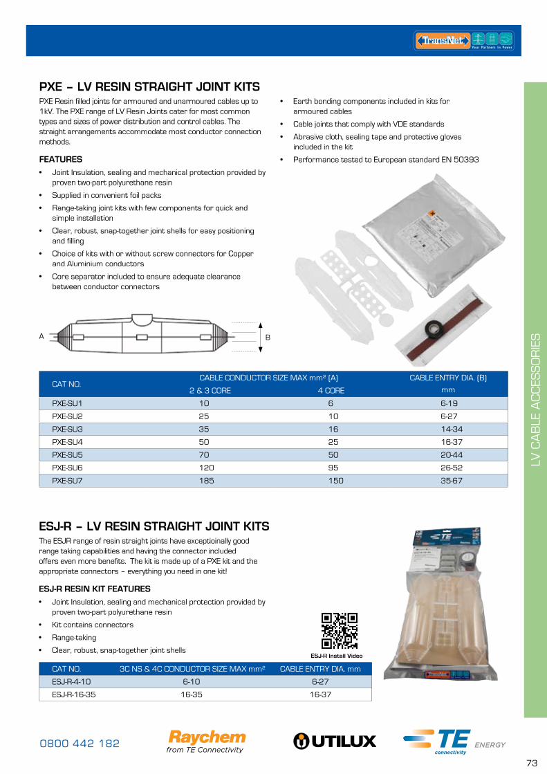
0800 442 182
73
LV C
AB
LE A
CC
ESS
OR
IESA B
ESJ-R Install Video
PXE – LV RESIN STRAIGHT JOINT KITS
CAT NO. CABLE CONDUCTOR SIZE MAX mm² (A) CABLE ENTRY DIA. (B)
mm2 & 3 CORE 4 CORE
PXE-SU1 10 6 6-19
PXE-SU2 25 10 6-27
PXE-SU3 35 16 14-34
PXE-SU4 50 25 16-37
PXE-SU5 70 50 20-44
PXE-SU6 120 95 26-52
PXE-SU7 185 150 35-67
CAT NO. 3C NS & 4C CONDUCTOR SIZE MAX mm² CABLE ENTRY DIA. mm
ESJ-R-4-10 6-10 6-27
ESJ-R-16-35 16-35 16-37
PXE Resin filled joints for armoured and unarmoured cables up to 1kV. The PXE range of LV Resin Joints cater for most common types and sizes of power distribution and control cables. The straight arrangements accommodate most conductor connection methods.
FEATURES• Joint Insulation, sealing and mechanical protection provided by
proven two-part polyurethane resin
• Supplied in convenient foil packs
• Range-taking joint kits with few components for quick and simple installation
• Clear, robust, snap-together joint shells for easy positioning and filling
• Choice of kits with or without screw connectors for Copper and Aluminium conductors
• Core separator included to ensure adequate clearance between conductor connectors
The ESJR range of resin straight joints have exceptioinally good range taking capabilities and having the connector included offers even more benefits. The kit is made up of a PXE kit and the appropriate connectors – everything you need in one kit!
ESJ-R RESIN KIT FEATURES• Joint Insulation, sealing and mechanical protection provided by
proven two-part polyurethane resin
• Kit contains connectors
• Range-taking
• Clear, robust, snap-together joint shells
• Earth bonding components included in kits for armoured cables
• Cable joints that comply with VDE standards
• Abrasive cloth, sealing tape and protective gloves included in the kit
• Performance tested to European standard EN 50393
ESJ-R – LV RESIN STRAIGHT JOINT KITS
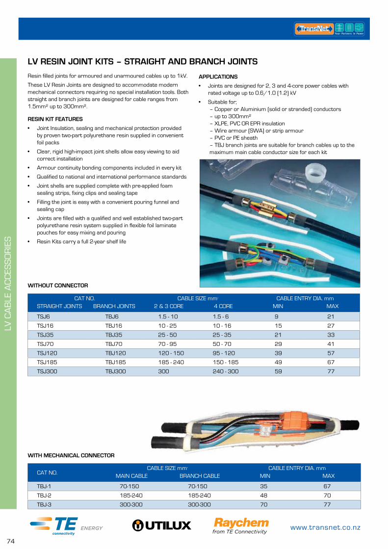
www.transnet.co.nz
74
LV C
AB
LE A
CC
ESS
OR
IES
WITHOUT CONNECTOR
WITH MECHANICAL CONNECTOR
CAT NO. CABLE SIZE mm² CABLE ENTRY DIA. mmSTRAIGHT JOINTS BRANCH JOINTS 2 & 3 CORE 4 CORE MIN MAX
TSJ6 TBJ6 1.5 - 10 1.5 - 6 9 21
TSJ16 TBJ16 10 - 25 10 - 16 15 27
TSJ35 TBJ35 25 - 50 25 - 35 21 33
TSJ70 TBJ70 70 - 95 50 - 70 29 41
TSJ120 TBJ120 120 - 150 95 - 120 39 57
TSJ185 TBJ185 185 - 240 150 - 185 49 67
TSJ300 TBJ300 300 240 - 300 59 77
CAT NO.CABLE SIZE mm² CABLE ENTRY DIA. mm
MAIN CABLE BRANCH CABLE MIN MAX
TBJ-1 70-150 70-150 35 67
TBJ-2 185-240 185-240 48 70
TBJ-3 300-300 300-300 70 77
LV RESIN JOINT KITS – STRAIGHT AND BRANCH JOINTS
Resin filled joints for armoured and unarmoured cables up to 1kV.
These LV Resin Joints are designed to accommodate modern mechanical connectors requiring no special installation tools. Both straight and branch joints are designed for cable ranges from 1.5mm² up to 300mm².
RESIN KIT FEATURES
• Joint Insulation, sealing and mechanical protection provided by proven two-part polyurethane resin supplied in convenient foil packs
• Clear, rigid high-impact joint shells allow easy viewing to aid correct installation
• Armour continuity bonding components included in every kit
• Qualified to national and international performance standards
• Joint shells are supplied complete with pre-applied foam sealing strips, fixing clips and sealing tape
• Filling the joint is easy with a convenient pouring funnel and sealing cap
• Joints are filled with a qualified and well established two-part polyurethane resin system supplied in flexible foil laminate pouches for easy mixing and pouring
• Resin Kits carry a full 2-year shelf life
APPLICATIONS
• Joints are designed for 2, 3 and 4-core power cables with rated voltage up to 0.6/1.0 (1.2) kV
• Suitable for; – Copper or Aluminium (solid or stranded) conductors – up to 300mm² – XLPE, PVC OR EPR insulation – Wire armour (SWA) or strip armour – PVC or PE sheath – TBJ branch joints are suitable for branch cables up to the maximum main cable conductor size for each kit
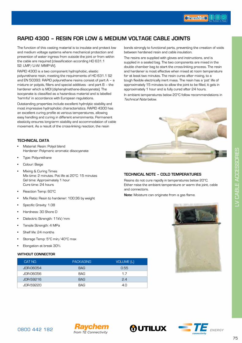
0800 442 182
75
LV C
AB
LE A
CC
ESS
OR
IES
bonds strongly to functional parts, preventing the creation of voids between hardened resin and cable insulation.
The resins are supplied with gloves and instructions, and is supplied in a sealed bag. The two components are mixed in the double chamber bag to start the cross-linking process. The resin and hardener is most effective when mixed at room temperature for at least two minutes. The resin cures after mixing, to a tough flexible electrically inert mass. The resin has a ‘pot’ life of approximately 15 minutes to allow the joint to be filled, it gels in approximately 1 hour and is fully cured after 24 hours.
In ambient temperatures below 20°C follow recommendations in Technical Note below.
WITHOUT CONNECTOR
TECHNICAL NOTE – COLD TEMPERATURES
TECHNICAL DATA
RAPID 4300 – RESIN FOR LOW & MEDIUM VOLTAGE CABLE JOINTS
CAT NO. PACKAGING VOLUME (L)
JOR-06054 BAG 0.55
JOR-06056 BAG 1.7
JOR-59216 BAG 2.4
JOR-59220 BAG 4.0
The function of this casting material is to insulate and protect low and medium voltage systems where mechanical protection and prevention of water ingress from outside the joint or from within the cable are required (classification according HD 631.1 S2: LMP/LI-W: MMP-W).
RAPID 4300 is a two component hydrophobic, elastic polyurethane resin, meeting the requirements of HD 631.1 S2 and EN 50393. RAPID polyurethane resins consist of part A – a mixture or polyols, fillers and special additives - and part B – the hardener which is MDI (diphenylmethane-diisocyanate). The isocyanate is classified as a hazardous material and is labelled ‘harmful’ in accordance with European regulations.
Outstanding properties include excellent hydrolytic stability and most impressive hydrophobic characteristics. RAPID 4300 has an excellent curing profile at various temperatures, allowing easy handling and curing in different environments. Permanent elasticity ensures long-term stability and accommodation of cable movement. As a result of the cross-linking reaction, the resin
Resins do not cure rapidly in temperatures below 20°C. Either raise the ambient temperature or warm the joint, cable and connectors.
Note: Moisture can originate from a gas flame.
• Material: Resin: Polyol blend Hardener: Polymeric aromatic diisocyanate
• Type: Polyurethane
• Colour: Beige
• Mixing & Curing Times Mix time: 2 minutes. Pot life at 20°C: 15 minutes Gel time: Approximately 1 hour Cure time: 24 hours
• Reaction Temp: 60°C
• Mix Ratio: Resin to hardener: 100:36 by weight
• Specific Gravity: 1.08
• Hardness: 30 Shore D
• Dielectric Strength: 11kV/mm
• Tensile Strength: 4 MPa
• Shelf life: 24 months
• Storage Temp: 5°C min/40°C max
• Elongation at break 30%
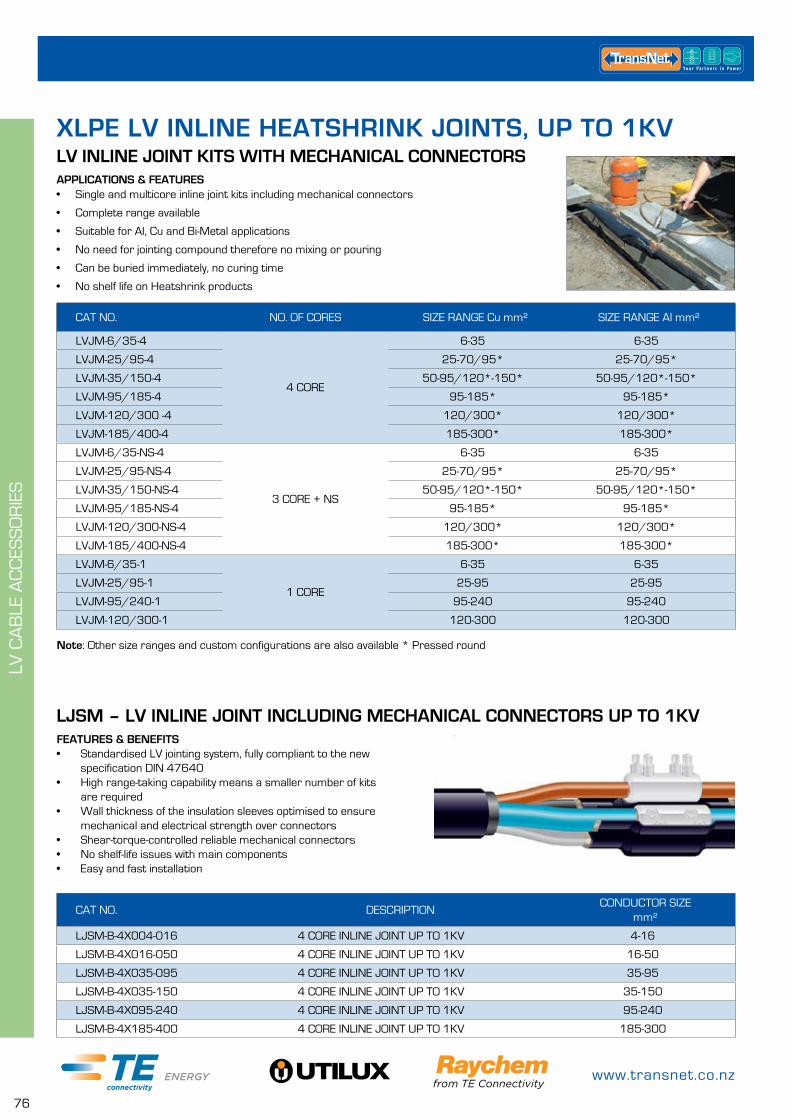
www.transnet.co.nz
76
LV C
AB
LE A
CC
ESS
OR
IES
CAT NO. DESCRIPTIONCONDUCTOR SIZE
mm²
LJSM-B-4X004-016 4 CORE INLINE JOINT UP TO 1KV 4-16
LJSM-B-4X016-050 4 CORE INLINE JOINT UP TO 1KV 16-50
LJSM-B-4X035-095 4 CORE INLINE JOINT UP TO 1KV 35-95
LJSM-B-4X035-150 4 CORE INLINE JOINT UP TO 1KV 35-150
LJSM-B-4X095-240 4 CORE INLINE JOINT UP TO 1KV 95-240
LJSM-B-4X185-400 4 CORE INLINE JOINT UP TO 1KV 185-300
APPLICATIONS & FEATURES• Single and multicore inline joint kits including mechanical connectors
• Complete range available
• Suitable for AI, Cu and Bi-Metal applications
• No need for jointing compound therefore no mixing or pouring
• Can be buried immediately, no curing time
• No shelf life on Heatshrink products
XLPE LV INLINE HEATSHRINK JOINTS, UP TO 1KV
Note: Other size ranges and custom configurations are also available * Pressed round
CAT NO. NO. OF CORES SIZE RANGE Cu mm² SIZE RANGE AI mm²
LVJM-6/35-4
4 CORE
6-35 6-35
LVJM-25/95-4 25-70/95* 25-70/95*
LVJM-35/150-4 50-95/120*-150* 50-95/120*-150*
LVJM-95/185-4 95-185* 95-185*
LVJM-120/300 -4 120/300* 120/300*
LVJM-185/400-4 185-300* 185-300*
LVJM-6/35-NS-4
3 CORE + NS
6-35 6-35
LVJM-25/95-NS-4 25-70/95* 25-70/95*
LVJM-35/150-NS-4 50-95/120*-150* 50-95/120*-150*
LVJM-95/185-NS-4 95-185* 95-185*
LVJM-120/300-NS-4 120/300* 120/300*
LVJM-185/400-NS-4 185-300* 185-300*
LVJM-6/35-1
1 CORE
6-35 6-35
LVJM-25/95-1 25-95 25-95
LVJM-95/240-1 95-240 95-240
LVJM-120/300-1 120-300 120-300
LV INLINE JOINT KITS WITH MECHANICAL CONNECTORS
LJSM – LV INLINE JOINT INCLUDING MECHANICAL CONNECTORS UP TO 1KVFEATURES & BENEFITS• Standardised LV jointing system, fully compliant to the new
specification DIN 47640• High range-taking capability means a smaller number of kits
are required• Wall thickness of the insulation sleeves optimised to ensure
mechanical and electrical strength over connectors• Shear-torque-controlled reliable mechanical connectors• No shelf-life issues with main components• Easy and fast installation
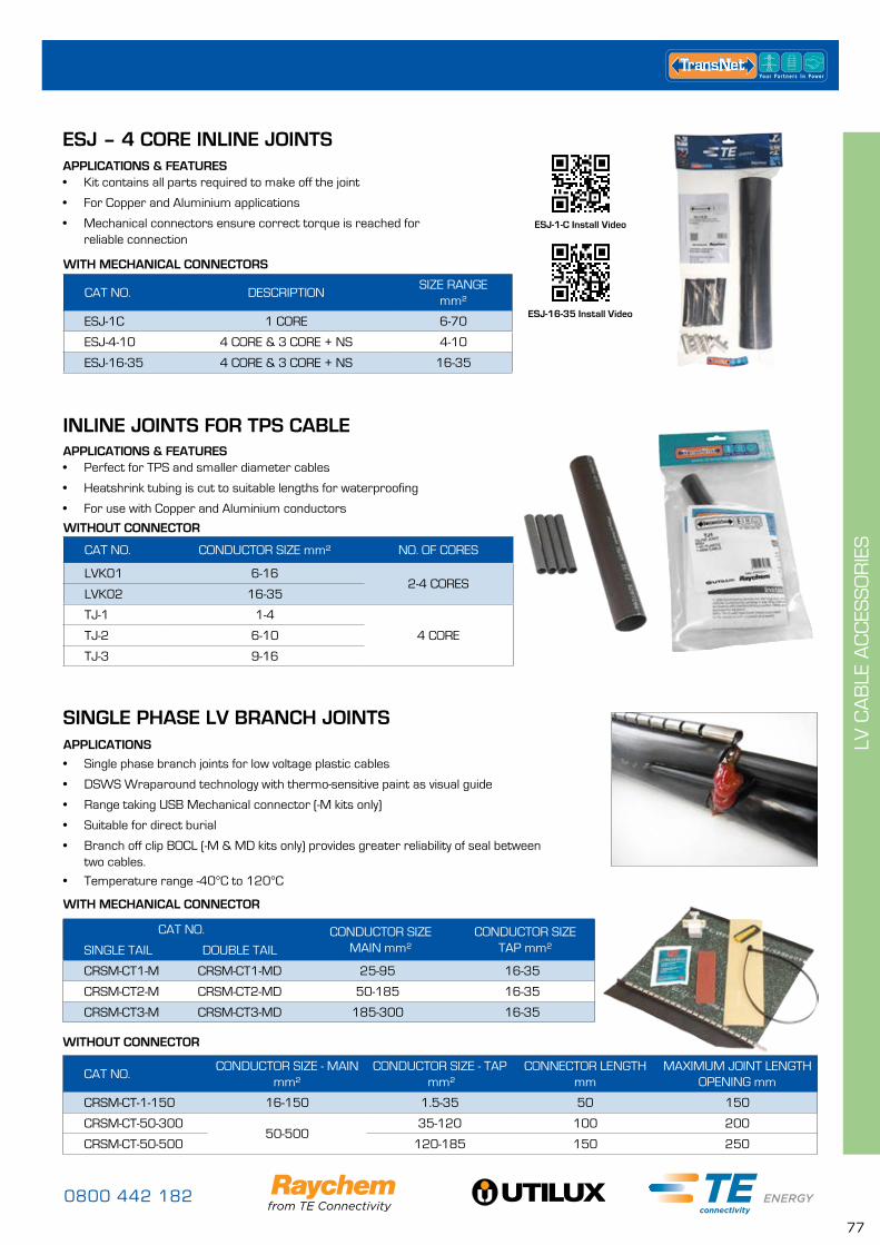
0800 442 182
77
LV C
AB
LE A
CC
ESS
OR
IES
APPLICATIONS
• Single phase branch joints for low voltage plastic cables
• DSWS Wraparound technology with thermo-sensitive paint as visual guide
• Range taking USB Mechanical connector (-M kits only)
• Suitable for direct burial
• Branch off clip BOCL (-M & MD kits only) provides greater reliability of seal between two cables.
• Temperature range -40°C to 120°C
CAT NO.CONDUCTOR SIZE - MAIN
mm²CONDUCTOR SIZE - TAP
mm²CONNECTOR LENGTH
mmMAXIMUM JOINT LENGTH
OPENING mm
CRSM-CT-1-150 16-150 1.5-35 50 150
CRSM-CT-50-30050-500
35-120 100 200
CRSM-CT-50-500 120-185 150 250
WITHOUT CONNECTOR
CAT NO. CONDUCTOR SIZE MAIN mm²
CONDUCTOR SIZE TAP mm²SINGLE TAIL DOUBLE TAIL
CRSM-CT1-M CRSM-CT1-MD 25-95 16-35
CRSM-CT2-M CRSM-CT2-MD 50-185 16-35
CRSM-CT3-M CRSM-CT3-MD 185-300 16-35
WITH MECHANICAL CONNECTOR
APPLICATIONS & FEATURES• Kit contains all parts required to make off the joint
• For Copper and Aluminium applications
• Mechanical connectors ensure correct torque is reached for reliable connection
APPLICATIONS & FEATURES• Perfect for TPS and smaller diameter cables
• Heatshrink tubing is cut to suitable lengths for waterproofing
• For use with Copper and Aluminium conductors
CAT NO. DESCRIPTIONSIZE RANGE
mm²
ESJ-1C 1 CORE 6-70
ESJ-4-10 4 CORE & 3 CORE + NS 4-10
ESJ-16-35 4 CORE & 3 CORE + NS 16-35
WITH MECHANICAL CONNECTORS
INLINE JOINTS FOR TPS CABLE
SINGLE PHASE LV BRANCH JOINTS
ESJ – 4 CORE INLINE JOINTS
CAT NO. CONDUCTOR SIZE mm² NO. OF CORES
LVK01 6-162-4 CORES
LVK02 16-35
TJ-1 1-4
4 CORETJ-2 6-10
TJ-3 9-16
WITHOUT CONNECTOR
ESJ-1-C Install Video
ESJ-16-35 Install Video
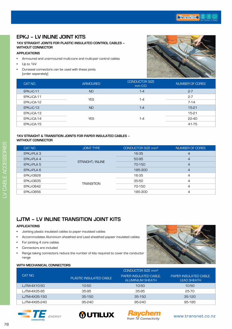
www.transnet.co.nz
78
LV C
AB
LE A
CC
ESS
OR
IES
APPLICATIONS
• Jointing plastic insulated cables to paper insulated cables
• Accommodates Aluminium sheathed and Lead sheathed papaer insulated cables
• For jointing 4 core cables
• Connectors are included
• Range taking connectors reduce the number of kits required to cover the conductor range
CAT NO.CONDUCTOR SIZE mm²
PLASTIC INSULATED CABLEPAPER INSULATED CABLE,
ALUMINIUM SHEATHPAPER INSULATED CABLE,
LEAD SHEATH
LJTM-4X10-50 10-50 10-50 10-50
LJTM-4X35-95 35-95 35-95 25-70
LJTM-4X35-150 35-150 35-150 35-120
LJTM-4X95-240 95-240 95-240 95-185
1KV STRAIGHT JOINTS FOR PLASTIC INSULATED CONTROL CABLES – WITHOUT CONNECTOR
1KV STRAIGHT & TRANSITION JOINTS FOR PAPER INSULATED CABLES – WITHOUT CONNECTOR
EPKJ – LV INLINE JOINT KITS
APPLICATIONS
• Armoured and unarmoured multi-core and multi-pair control cables
• Up to 1kV
• Duraseal connectors can be used with these joints (order separately)
CAT NO. ARMOUREDCONDUCTOR SIZE
mm O.D.NUMBER OF CORES
EPKJ-C-11 NO 1-4 2-7
EPKJ-CA-11YES 1-4
2-7
EPKJ-CA-12 7-14
EPKJ-C-13 NO 1-4 15-21
EPKJ-CA-13
YES 1-4
15-21
EPKJ-CA-14 22-40
EPKJ-CA-15 41-75
1KV TRANSITION JOINTS FOR PAPER TO PLASTIC CABLES
CAT NO. JOINT TYPE CONDUCTOR SIZE mm² NUMBER OF CORES
EPKJ-PLA 3
STRAIGHT/INLINE
16-35 4
EPKJ-PLA 4 50-95 4
EPKJ-PLA 5 70-150 4
EPKJ-PLA 6 185-300 4
EPKJ-0828
TRANSITION
16-35 4
EPKJ-0835 35-50 4
EPKJ-0842 70-150 4
EPKJ-0856 185-300 4
WITH MECHANICAL CONNECTORS
LJTM – LV INLINE TRANSITION JOINT KITS
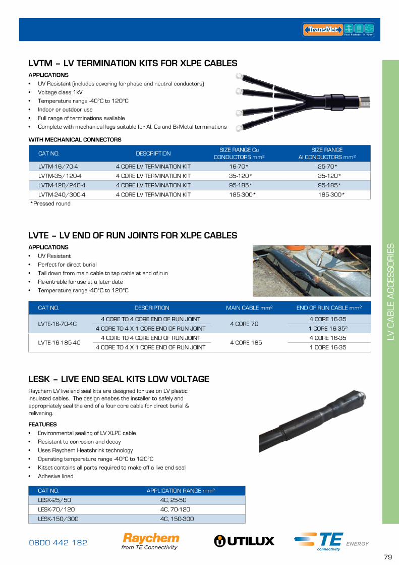
0800 442 182
79
LV C
AB
LE A
CC
ESS
OR
IES
APPLICATIONS
• UV Resistant (includes covering for phase and neutral conductors)
• Voltage class 1kV
• Temperature range -40°C to 120°C
• Indoor or outdoor use
• Full range of terminations available
• Complete with mechanical lugs suitable for Al, Cu and Bi-Metal terminations
APPLICATIONS
• UV Resistant
• Perfect for direct burial
• Tail down from main cable to tap cable at end of run
• Re-entrable for use at a later date
• Temperature range -40°C to 120°C
LVTM – LV TERMINATION KITS FOR XLPE CABLES
CAT NO. DESCRIPTIONSIZE RANGE Cu
CONDUCTORS mm²SIZE RANGE
AI CONDUCTORS mm²
LVTM-16/70-4 4 CORE LV TERMINATION KIT 16-70* 25-70*
LVTM-35/120-4 4 CORE LV TERMINATION KIT 35-120* 35-120*
LVTM-120/240-4 4 CORE LV TERMINATION KIT 95-185* 95-185*
LVTM-240/300-4 4 CORE LV TERMINATION KIT 185-300* 185-300*
*Pressed round
LESK – LIVE END SEAL KITS LOW VOLTAGERaychem LV live end seal kits are designed for use on LV plastic insulated cables. The design enabes the installer to safely and appropriately seal the end of a four core cable for direct burial & relivening.
FEATURES
• Environmental sealing of LV XLPE cable
• Resistant to corrosion and decay
• Uses Raychem Heatshrink technology
• Operating temperature range -40°C to 120°C
• Kitset contains all parts required to make off a live end seal
• Adhesive lined
CAT NO. APPLICATION RANGE mm²
LESK-25/50 4C, 25-50
LESK-70/120 4C, 70-120
LESK-150/300 4C, 150-300
CAT NO. DESCRIPTION MAIN CABLE mm² END OF RUN CABLE mm²
LVTE-16-70-4C4 CORE TO 4 CORE END OF RUN JOINT
4 CORE 704 CORE 16-35
4 CORE TO 4 X 1 CORE END OF RUN JOINT 1 CORE 16-35²
LVTE-16-185-4C4 CORE TO 4 CORE END OF RUN JOINT
4 CORE 1854 CORE 16-35
4 CORE TO 4 X 1 CORE END OF RUN JOINT 1 CORE 16-35
LVTE – LV END OF RUN JOINTS FOR XLPE CABLES
WITH MECHANICAL CONNECTORS
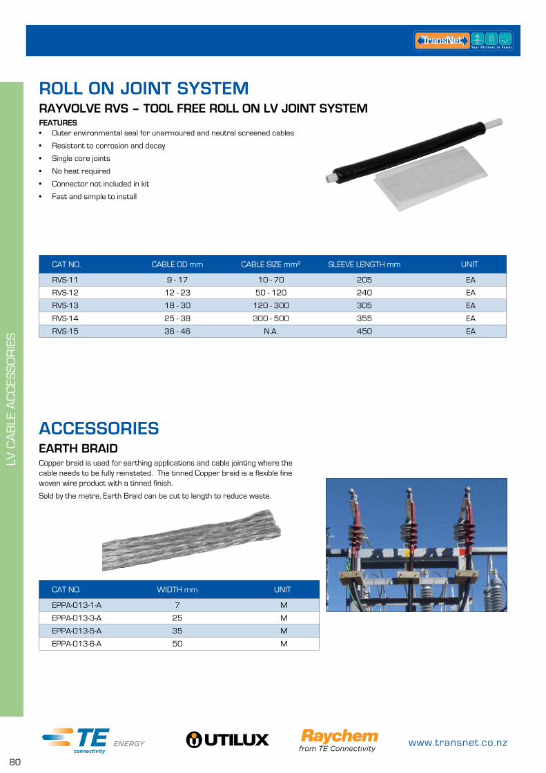
www.transnet.co.nz
80
LV C
AB
LE A
CC
ESS
OR
IES
RAYVOLVE RVS – TOOL FREE ROLL ON LV JOINT SYSTEMFEATURES• Outer environmental seal for unarmoured and neutral screened cables
• Resistant to corrosion and decay
• Single core joints
• No heat required
• Connector not included in kit
• Fast and simple to install
CAT NO. CABLE OD mm CABLE SIZE mm² SLEEVE LENGTH mm UNIT
RVS-11 9 - 17 10 - 70 205 EA
RVS-12 12 - 23 50 - 120 240 EA
RVS-13 18 - 30 120 - 300 305 EA
RVS-14 25 - 38 300 - 500 355 EA
RVS-15 36 - 46 N.A. 450 EA
ROLL ON JOINT SYSTEM
EARTH BRAIDCopper braid is used for earthing applications and cable jointing where the cable needs to be fully reinstated. The tinned Copper braid is a flexible fine woven wire product with a tinned finish.
Sold by the metre, Earth Braid can be cut to length to reduce waste.
CAT NO. WIDTH mm UNIT
EPPA-013-1-A 7 M
EPPA-013-3-A 25 M
EPPA-013-5-A 35 M
EPPA-013-6-A 50 M
ACCESSORIES
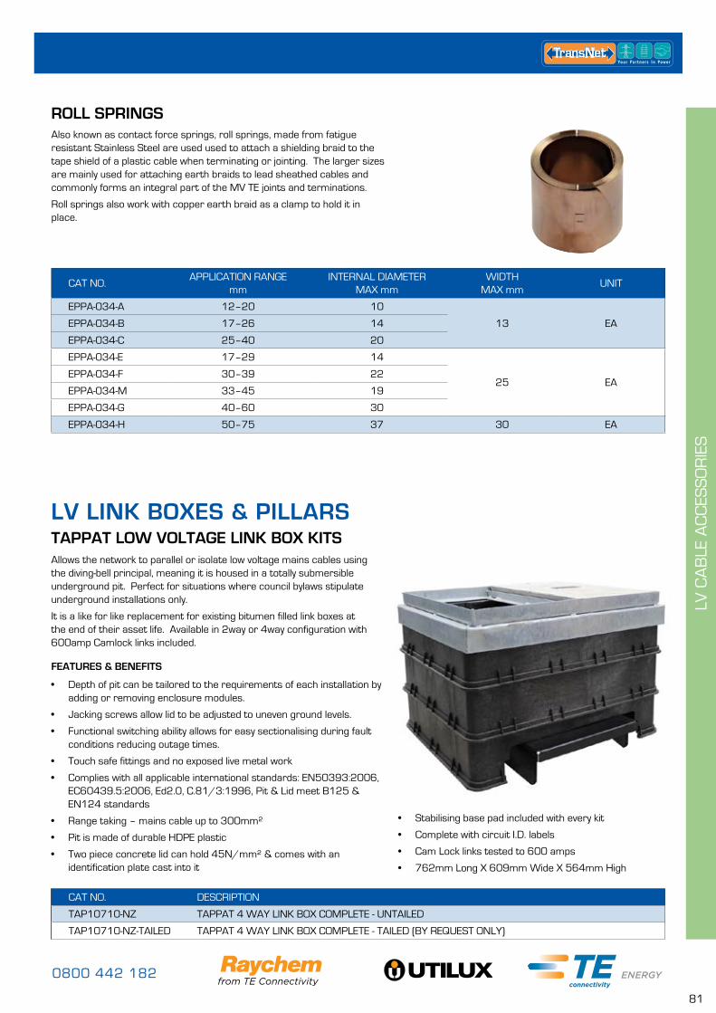
0800 442 182
81
LV C
AB
LE A
CC
ESS
OR
IES
LV LINK BOXES & PILLARSTAPPAT LOW VOLTAGE LINK BOX KITSAllows the network to parallel or isolate low voltage mains cables using the diving-bell principal, meaning it is housed in a totally submersible underground pit. Perfect for situations where council bylaws stipulate underground installations only.
It is a like for like replacement for existing bitumen filled link boxes at the end of their asset life. Available in 2way or 4way configuration with 600amp Camlock links included.
FEATURES & BENEFITS
• Depth of pit can be tailored to the requirements of each installation by adding or removing enclosure modules.
• Jacking screws allow lid to be adjusted to uneven ground levels.
• Functional switching ability allows for easy sectionalising during fault conditions reducing outage times.
• Touch safe fittings and no exposed live metal work
• Complies with all applicable international standards: EN50393:2006, EC60439.5:2006, Ed2.0, C.81/3:1996, Pit & Lid meet B125 & EN124 standards
• Range taking – mains cable up to 300mm²
• Pit is made of durable HDPE plastic
• Two piece concrete lid can hold 45N/mm² & comes with an identification plate cast into it
CAT NO. DESCRIPTION
TAP10710-NZ TAPPAT 4 WAY LINK BOX COMPLETE - UNTAILED
TAP10710-NZ-TAILED TAPPAT 4 WAY LINK BOX COMPLETE - TAILED (BY REQUEST ONLY)
• Stabilising base pad included with every kit
• Complete with circuit I.D. labels
• Cam Lock links tested to 600 amps
• 762mm Long X 609mm Wide X 564mm High
ROLL SPRINGSAlso known as contact force springs, roll springs, made from fatigue resistant Stainless Steel are used used to attach a shielding braid to the tape shield of a plastic cable when terminating or jointing. The larger sizes are mainly used for attaching earth braids to lead sheathed cables and commonly forms an integral part of the MV TE joints and terminations.
Roll springs also work with copper earth braid as a clamp to hold it in place.
CAT NO.APPLICATION RANGE
mmINTERNAL DIAMETER
MAX mmWIDTH
MAX mmUNIT
EPPA-034-A 12–20 10
13 EAEPPA-034-B 17–26 14
EPPA-034-C 25–40 20
EPPA-034-E 17–29 14
25 EAEPPA-034-F 30–39 22
EPPA-034-M 33–45 19
EPPA-034-G 40–60 30
EPPA-034-H 50–75 37 30 EA
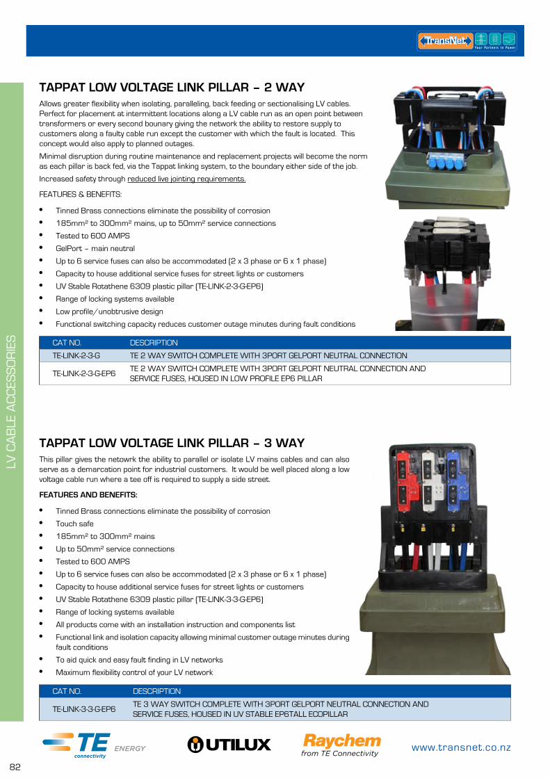
www.transnet.co.nz
82
LV C
AB
LE A
CC
ESS
OR
IES
CAT NO. DESCRIPTION
TE-LINK-3-3-G-EP6TE 3 WAY SWITCH COMPLETE WITH 3PORT GELPORT NEUTRAL CONNECTION AND SERVICE FUSES, HOUSED IN UV STABLE EP6TALL ECOPILLAR
TAPPAT LOW VOLTAGE LINK PILLAR – 3 WAYThis pillar gives the netowrk the ability to parallel or isolate LV mains cables and can also serve as a demarcation point for industrial customers. It would be well placed along a low voltage cable run where a tee off is required to supply a side street.
FEATURES AND BENEFITS:
• Tinned Brass connections eliminate the possibility of corrosion
• Touch safe
• 185mm² to 300mm² mains
• Up to 50mm² service connections
• Tested to 600 AMPS
• Up to 6 service fuses can also be accommodated (2 x 3 phase or 6 x 1 phase)
• Capacity to house additional service fuses for street lights or customers
• UV Stable Rotathene 6309 plastic pillar (TE-LINK-3-3-G-EP6)
• Range of locking systems available
• All products come with an installation instruction and components list
• Functional link and isolation capacity allowing minimal customer outage minutes during fault conditions
• To aid quick and easy fault finding in LV networks
• Maximum flexibility control of your LV network
CAT NO. DESCRIPTION
TE-LINK-2-3-G TE 2 WAY SWITCH COMPLETE WITH 3PORT GELPORT NEUTRAL CONNECTION
TE-LINK-2-3-G-EP6TE 2 WAY SWITCH COMPLETE WITH 3PORT GELPORT NEUTRAL CONNECTION AND SERVICE FUSES, HOUSED IN LOW PROFILE EP6 PILLAR
TAPPAT LOW VOLTAGE LINK PILLAR – 2 WAYAllows greater flexibility when isolating, paralleling, back feeding or sectionalising LV cables. Perfect for placement at intermittent locations along a LV cable run as an open point between transformers or every second bounary giving the network the ability to restore supply to customers along a faulty cable run except the customer with which the fault is located. This concept would also apply to planned outages.
Minimal disruption during routine maintenance and replacement projects will become the norm as each pillar is back fed, via the Tappat linking system, to the boundary either side of the job.
Increased safety through reduced live jointing requirements.
FEATURES & BENEFITS:
• Tinned Brass connections eliminate the possibility of corrosion
• 185mm² to 300mm² mains, up to 50mm² service connections
• Tested to 600 AMPS
• GelPort – main neutral
• Up to 6 service fuses can also be accommodated (2 x 3 phase or 6 x 1 phase)
• Capacity to house additional service fuses for street lights or customers
• UV Stable Rotathene 6309 plastic pillar (TE-LINK-2-3-G-EP6)
• Range of locking systems available
• Low profile/unobtrusive design
• Functional switching capacity reduces customer outage minutes during fault conditions
0800 442 182
83
MV
CA
BLE
AC
CES
SO
RIE
S
XLPE TERMINATION KITS PAGE
Crucifix Brackets 11kV & 33kV 84
11kV 84
22kV 85
33kV 86
PILC TERMINATION KITS PAGE
11kV 87
22kV 87
33kV 88
EARTHING KITS PAGE
EAKT – Paper Lead Armour, SEK – Copper Tape Screen, AEK – Steel Wire Armour 88
Earth Bars 88
INSULATION BUSHING BOOTS PAGE
11kV RSRB Heatshrinkable 89
11kV RIBS & RCAB Cold Applied 89
SCREENED ELBOW TERMINATION KITS PAGE
RSES For Type A Bushings 90
RSSS For Type A Bushings 90
RICS Insulated Elbows 90
RSTI Insulated Screened Elbows 91
RSTI-CC Piggyback Coupling System 91
RSTI-SA Surge Arrestor for Insulated Screened Elbows 92
Accessories 92
RPITS PAGE
Plug in Termination for Gas Insulated Switchgear 42kV 93
TRIFURCATING KITS PAGE
11kV Trifurcating Kits for XLPE Cable 93
XLPE JOINT KITS PAGE
11kV 94
22kV 95
33kV 97
PILC JOINT KITS PAGE
11kV 99
33kV 99
TRANSITION JOINT KITS PAGE
11kV 100
22kV 100
33kV 101
LIVE END SEALS PAGE
11kV 101
22kV 101
CABLE JOINTING TOOLS PAGE
General Jointing Tools 102
Specialist Stripping Tools 105
Cable Spiker 107
MV CABLE ACCESSORIES
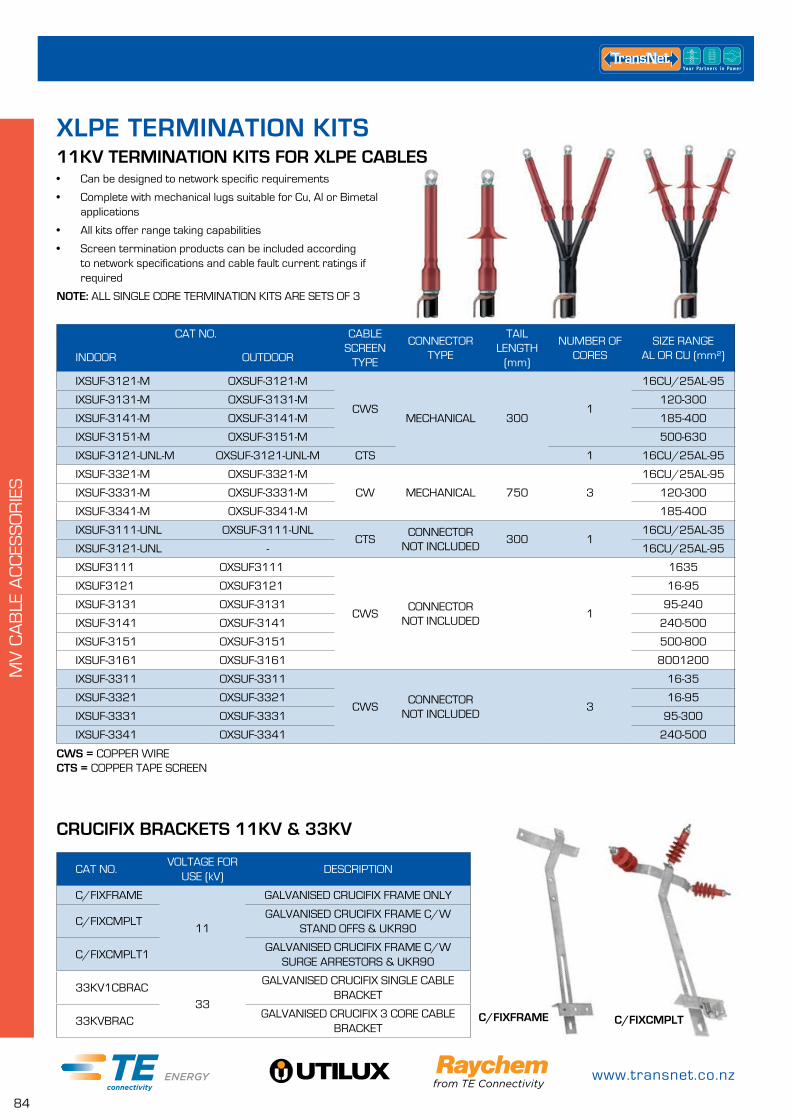
www.transnet.co.nz
84
MV
CA
BLE
AC
CES
SO
RIE
S
• Can be designed to network specific requirements
• Complete with mechanical lugs suitable for Cu, Al or Bimetal applications
• All kits offer range taking capabilities
• Screen termination products can be included according to network specifications and cable fault current ratings if required
NOTE: ALL SINGLE CORE TERMINATION KITS ARE SETS OF 3
11KV TERMINATION KITS FOR XLPE CABLES
CAT NO. CABLE SCREEN
TYPE
CONNECTOR TYPE
TAIL LENGTH
(mm)
NUMBER OF CORES
SIZE RANGE AL OR CU (mm²)INDOOR OUTDOOR
IXSUF-3121-M OXSUF-3121-M
CWSMECHANICAL 300
1
16CU/25AL-95
IXSUF-3131-M OXSUF-3131-M 120-300
IXSUF-3141-M OXSUF-3141-M 185-400
IXSUF-3151-M OXSUF-3151-M 500-630
IXSUF-3121-UNL-M OXSUF-3121-UNL-M CTS 1 16CU/25AL-95
IXSUF-3321-M OXSUF-3321-M
CW MECHANICAL 750 3
16CU/25AL-95
IXSUF-3331-M OXSUF-3331-M 120-300
IXSUF-3341-M OXSUF-3341-M 185-400
IXSUF-3111-UNL OXSUF-3111-UNLCTS
CONNECTOR NOT INCLUDED
300 116CU/25AL-35
IXSUF-3121-UNL - 16CU/25AL-95
IXSUF3111 OXSUF3111
CWSCONNECTOR
NOT INCLUDED1
1635
IXSUF3121 OXSUF3121 16-95
IXSUF-3131 OXSUF-3131 95-240
IXSUF-3141 OXSUF-3141 240-500
IXSUF-3151 OXSUF-3151 500-800
IXSUF-3161 OXSUF-3161 8001200
IXSUF-3311 OXSUF-3311
CWSCONNECTOR
NOT INCLUDED3
16-35
IXSUF-3321 OXSUF-3321 16-95
IXSUF-3331 OXSUF-3331 95-300
IXSUF-3341 OXSUF-3341 240-500
XLPE TERMINATION KITS
CAT NO.VOLTAGE FOR
USE (kV)DESCRIPTION
C/FIXFRAME
11
GALVANISED CRUCIFIX FRAME ONLY
C/FIXCMPLTGALVANISED CRUCIFIX FRAME C/W
STAND OFFS & UKR90
C/FIXCMPLT1GALVANISED CRUCIFIX FRAME C/W
SURGE ARRESTORS & UKR90
33KV1CBRAC33
GALVANISED CRUCIFIX SINGLE CABLE BRACKET
33KVBRACGALVANISED CRUCIFIX 3 CORE CABLE
BRACKET
CRUCIFIX BRACKETS 11KV & 33KV
CWS = COPPER WIRE CTS = COPPER TAPE SCREEN
C/FIXCMPLTC/FIXFRAME
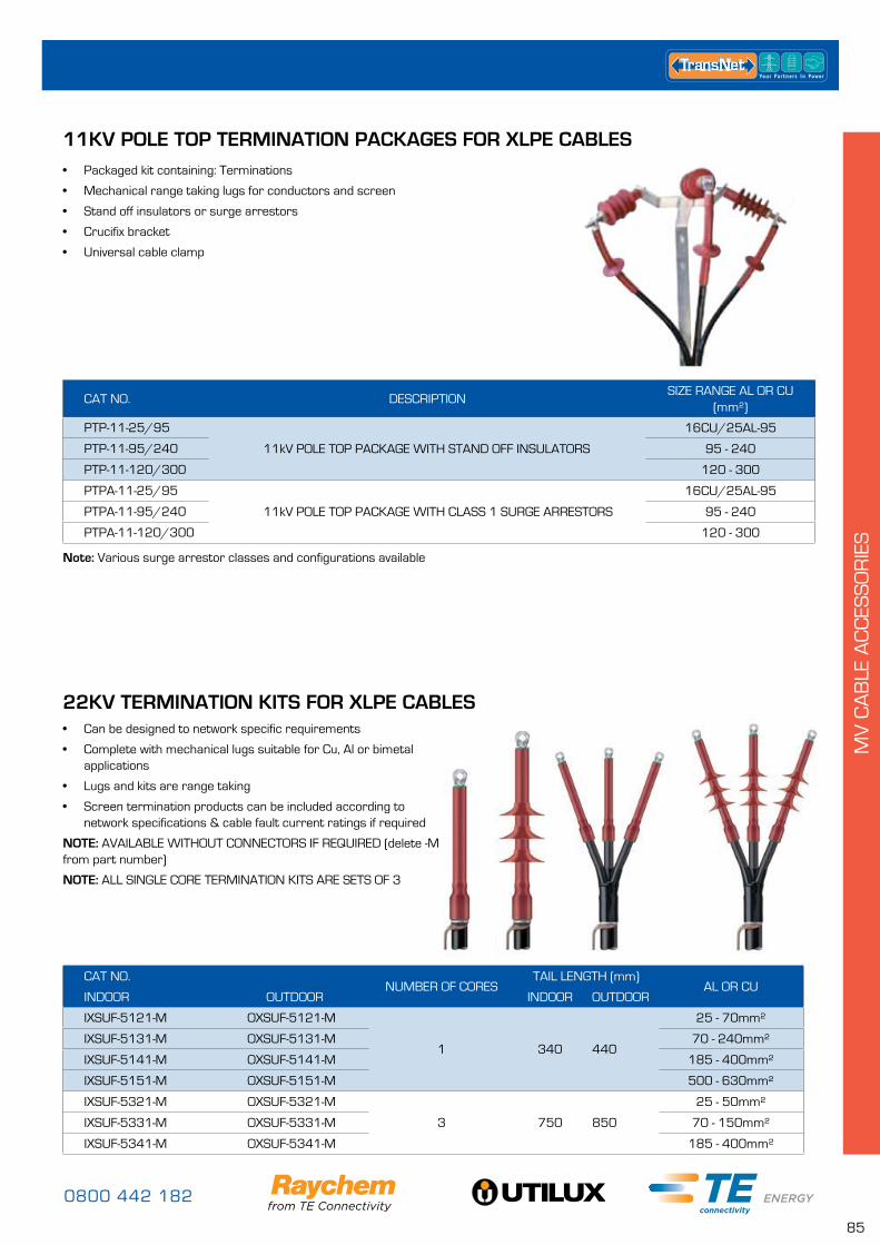
0800 442 182
85
MV
CA
BLE
AC
CES
SO
RIE
S
11KV POLE TOP TERMINATION PACKAGES FOR XLPE CABLES• Packaged kit containing: Terminations
• Mechanical range taking lugs for conductors and screen
• Stand off insulators or surge arrestors
• Crucifix bracket
• Universal cable clamp
CAT NO. DESCRIPTIONSIZE RANGE AL OR CU
(mm²)
PTP-11-25/95
11kV POLE TOP PACKAGE WITH STAND OFF INSULATORS
16CU/25AL-95
PTP-11-95/240 95 - 240
PTP-11-120/300 120 - 300
PTPA-11-25/95
11kV POLE TOP PACKAGE WITH CLASS 1 SURGE ARRESTORS
16CU/25AL-95
PTPA-11-95/240 95 - 240
PTPA-11-120/300 120 - 300
Note: Various surge arrestor classes and configurations available
22KV TERMINATION KITS FOR XLPE CABLES
CAT NO.NUMBER OF CORES
TAIL LENGTH (mm)AL OR CU
INDOOR OUTDOOR INDOOR OUTDOOR
IXSUF-5121-M OXSUF-5121-M
1 340 440
25 - 70mm²
IXSUF-5131-M OXSUF-5131-M 70 - 240mm²
IXSUF-5141-M OXSUF-5141-M 185 - 400mm²
IXSUF-5151-M OXSUF-5151-M 500 - 630mm²
IXSUF-5321-M OXSUF-5321-M
3 750 850
25 - 50mm²
IXSUF-5331-M OXSUF-5331-M 70 - 150mm²
IXSUF-5341-M OXSUF-5341-M 185 - 400mm²
• Can be designed to network specific requirements
• Complete with mechanical lugs suitable for Cu, Al or bimetal applications
• Lugs and kits are range taking
• Screen termination products can be included according to network specifications & cable fault current ratings if required
NOTE: AVAILABLE WITHOUT CONNECTORS IF REQUIRED (delete -M from part number)
NOTE: ALL SINGLE CORE TERMINATION KITS ARE SETS OF 3
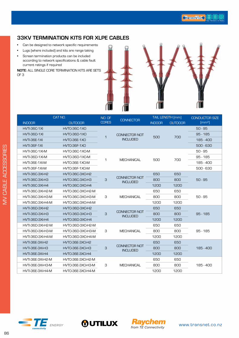
www.transnet.co.nz
86
MV
CA
BLE
AC
CES
SO
RIE
S
33KV TERMINATION KITS FOR XLPE CABLES
CAT NO. NO. OF CORES
CONNECTORTAIL LENGTH (mm) CONDUCTOR SIZE
(mm²)INDOOR OUTDOOR INDOOR OUTDOOR
HVTI-36C-1XI HVTO-36C-1XO
1CONNECTOR NOT
INCLUDED500 700
50 - 95
HVTI-36D-1XI HVTO-36D-1XO 95 - 185
HVTI-36E-1XI HVTO-36E-1XO 185 - 400
HVTI-36F-1XI HVTO-36F-1XO 500 - 630
HVTI-36C-1XI-M HVTO-36C-1XO-M
1 MECHANICAL 500 700
50 - 95
HVTI-36D-1XI-M HVTO-36D-1XO-M 95 - 185
HVTI-36E-1XI-M HVTO-36E-1XO-M 185 - 400
HVTI-36F-1XI-M HVTO-36F-1XO-M 500 - 630
HVTI-36C-3XI-H2 HVTO-36C-3XO-H2
3CONNECTOR NOT
INCLUDED
650 650
50 - 95HVTI-36C-3XI-H3 HVTO-36C-3XO-H3 800 800
HVTI-36C-3XI-H4 HVTO-36C-3XO-H4 1200 1200
HVTI-36C-3XI-H2-M HVTO-36C-3XO-H2-M
3 MECHANICAL
650 650
50 - 95HVTI-36C-3XI-H3-M HVTO-36C-3XO-H3-M 800 800
HVTI-36C-3XI-H4-M HVTO-36C-3XO-H4-M 1200 1200
HVTI-36D-3XI-H2 HVTO-36D-3XO-H2
3CONNECTOR NOT
INCLUDED
650 650
95 - 185HVTI-36D-3XI-H3 HVTO-36D-3XO-H3 800 800
HVTI-36D-3XI-H4 HVTO-36D-3XO-H4 1200 1200
HVTI-36D-3XI-H2-M HVTO-36D-3XO-H2-M
3 MECHANICAL
650 650
95 - 185HVTI-36D-3XI-H3-M HVTO-36D-3XO-H3-M 800 800
HVTI-36D-3XI-H4-M HVTO-36D-3XO-H4-M 1200 1200
HVTI-36E-3XI-H2 HVTO-36E-3XO-H2
3CONNECTOR NOT
INCLUDED
650 650
185 - 400HVTI-36E-3XI-H3 HVTO-36E-3XO-H3 800 800
HVTI-36E-3XI-H4 HVTO-36E-3XO-H4 1200 1200
HVTI-36E-3XI-H2-M HVTO-36E-3XO-H2-M
3 MECHANICAL
650 650
185 - 400HVTI-36E-3XI-H3-M HVTO-36E-3XO-H3-M 800 800
HVTI-36E-3XI-H4-M HVTO-36E-3XO-H4-M 1200 1200
• Can be designed to network specific requirements
• Lugs (where included) and kits are range taking
• Screen termination products can be included according to network specifications & cable fault current ratings if required
NOTE: ALL SINGLE CORE TERMINATION KITS ARE SETS OF 3
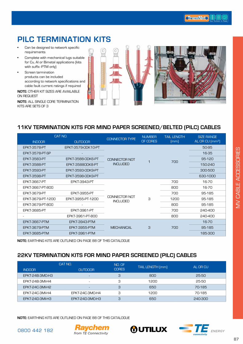
0800 442 182
87
MV
CA
BLE
AC
CES
SO
RIE
S
• Can be designed to network specific requirements
• Complete with mechanical lugs suitable for Cu, Al or Bimetal applications (kits with suffix -PTM only)
• Screen termination products can be included according to network specifications and cable fault current ratings if required
NOTE: OTHER KIT SIZES ARE AVAILABLE ON REQUEST
NOTE: ALL SINGLE CORE TERMINATION KITS ARE SETS OF 3
11KV TERMINATION KITS FOR MIND PAPER SCREENED/BELTED (PILC) CABLES
CAT NO.CONNECTOR TYPE
NUMBER OF CORES
TAIL LENGTH (mm)
SIZE RANGE AL OR CU (mm²)INDOOR OUTDOOR
EPKT-3578-PT EPKT-3579-ODK10-PT
CONNECTOR NOT INCLUDED
1 700
50-95
EPKT-3578-PT-SP - 16-35
EPKT-3583-PT EPKT-3588-ODK6-PT 95-120
EPKT-3588-PT EPKT-3588ODK8-PT 150-240
EPKT-3593-PT EPKT-3593-ODK9-PT 300-500
EPKT-3598-PT EPKT-3598-ODK9-PT 630-1000
EPKT-3667-PT EPKT-3943-PT
CONNECTOR NOT INCLUDED
3
700 16-70
EPKT-3667-PT-800 800 16-70
EPKT-3679-PT EPKT-3955-PT 700 95-185
EPKT-3679-PT-1200 EPKT-3955-PT-1200 1200 95-185
EPKT-3679-PT-800 - 800 95-185
EPKT-3685-PT EPKT-3961-PT 700 240-400
- EPKT-3961-PT-800 800 240-400
EPKT-3667-PTM EPKT-3943-PTM
MECHANICAL 3 700
16-70
EPKT-3679-PTM EPKT-3955-PTM 95-185
EPKT-3685-PTM EPKT-3961-PTM 185-300
22KV TERMINATION KITS FOR MIND PAPER SCREENED (PILC) CABLES
CAT NO. NO. OF CORES
TAIL LENGTH (mm) AL OR CUINDOOR OUTDOOR
EPKT-24B-3MO-H3 - 3 800 25-50
EPKT-24B-3MI-H4 - 3 1200 25-50
EPKT-24C-3MI-H2 - 3 650 70-185
EPKT-24C-3MI-H4 EPKT-24C-3MO-H4 3 1200 70-185
EPKT-24D-3MI-H3 EPKT-24D-3MO-H3 3 650 240-300
PILC TERMINATION KITS
NOTE: EARTHING KITS ARE OUTLINED ON PAGE 88 OF THIS CATALOGUE
NOTE: EARTHING KITS ARE OUTLINED ON PAGE 88 OF THIS CATALOGUE
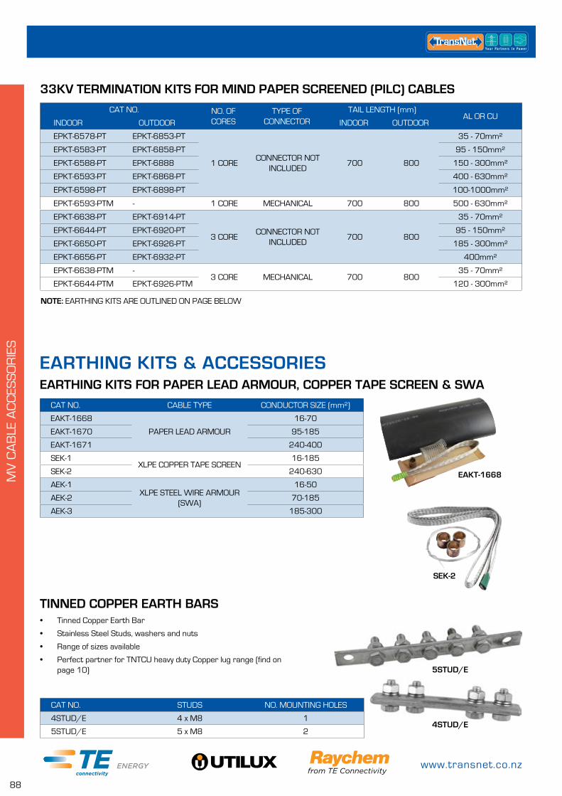
www.transnet.co.nz
88
MV
CA
BLE
AC
CES
SO
RIE
S
• Tinned Copper Earth Bar
• Stainless Steel Studs, washers and nuts
• Range of sizes available
• Perfect partner for TNTCU heavy duty Copper lug range (find on page 10)
CAT NO. NO. OF CORES
TYPE OF CONNECTOR
TAIL LENGTH (mm)AL OR CU
INDOOR OUTDOOR INDOOR OUTDOOR
EPKT-6578-PT EPKT-6853-PT
1 CORECONNECTOR NOT
INCLUDED700 800
35 - 70mm²
EPKT-6583-PT EPKT-6858-PT 95 - 150mm²
EPKT-6588-PT EPKT-6888 150 - 300mm²
EPKT-6593-PT EPKT-6868-PT 400 - 630mm²
EPKT-6598-PT EPKT-6898-PT 100-1000mm²
EPKT-6593-PTM - 1 CORE MECHANICAL 700 800 500 - 630mm²
EPKT-6638-PT EPKT-6914-PT
3 CORECONNECTOR NOT
INCLUDED700 800
35 - 70mm²
EPKT-6644-PT EPKT-6920-PT 95 - 150mm²
EPKT-6650-PT EPKT-6926-PT 185 - 300mm²
EPKT-6656-PT EPKT-6932-PT 400mm²
EPKT-6638-PTM -3 CORE MECHANICAL 700 800
35 - 70mm²
EPKT-6644-PTM EPKT-6926-PTM 120 - 300mm²
33KV TERMINATION KITS FOR MIND PAPER SCREENED (PILC) CABLES
CAT NO. CABLE TYPE CONDUCTOR SIZE (mm²)
EAKT-1668
PAPER LEAD ARMOUR
16-70
EAKT-1670 95-185
EAKT-1671 240-400
SEK-1XLPE COPPER TAPE SCREEN
16-185
SEK-2 240-630
AEK-1XLPE STEEL WIRE ARMOUR
(SWA)
16-50
AEK-2 70-185
AEK-3 185-300
EARTHING KITS & ACCESSORIESEARTHING KITS FOR PAPER LEAD ARMOUR, COPPER TAPE SCREEN & SWA
NOTE: EARTHING KITS ARE OUTLINED ON PAGE BELOW
TINNED COPPER EARTH BARS
CAT NO. STUDS NO. MOUNTING HOLES
4STUD/E 4 x M8 1
5STUD/E 5 x M8 2
5STUD/E
4STUD/E
SEK-2
EAKT-1668
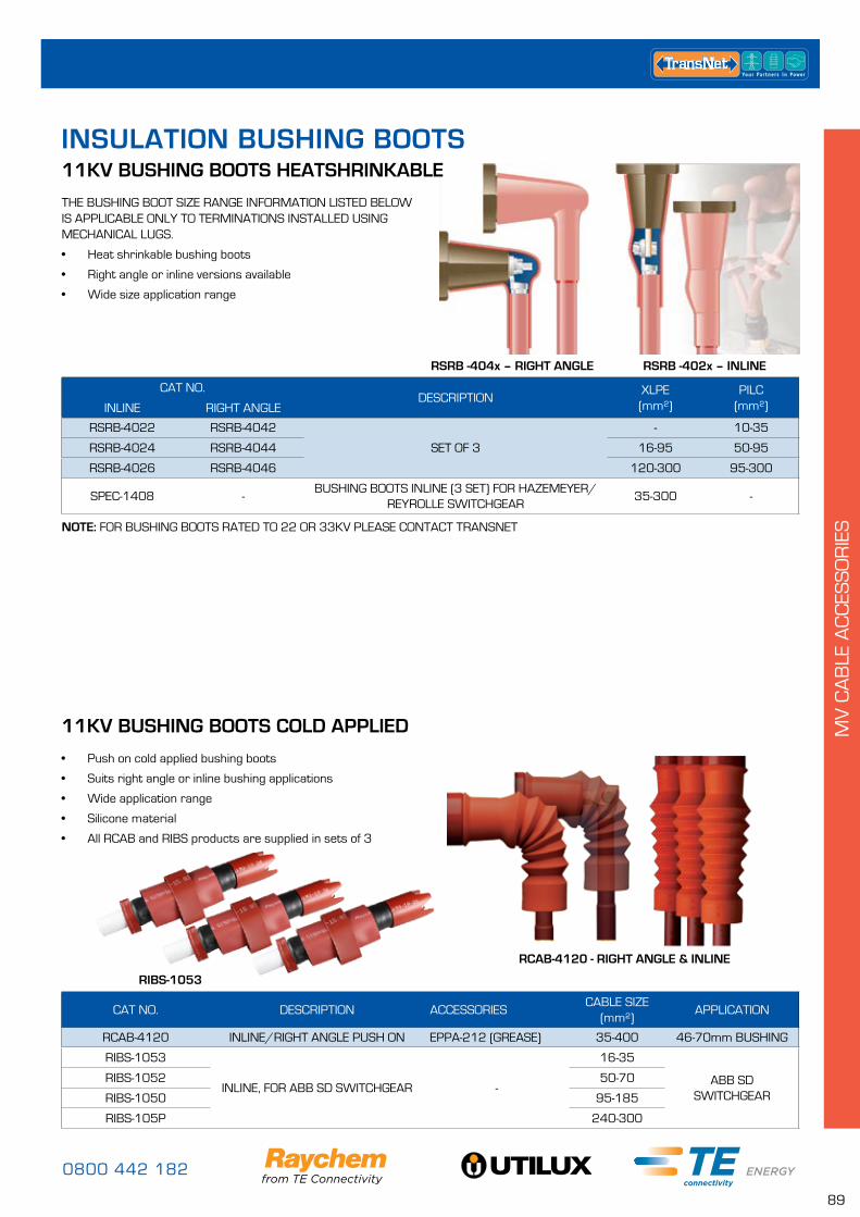
0800 442 182
89
MV
CA
BLE
AC
CES
SO
RIE
S
RSRB -404x – RIGHT ANGLE
THE BUSHING BOOT SIZE RANGE INFORMATION LISTED BELOW IS APPLICABLE ONLY TO TERMINATIONS INSTALLED USING MECHANICAL LUGS.
• Heat shrinkable bushing boots
• Right angle or inline versions available
• Wide size application range
• Push on cold applied bushing boots
• Suits right angle or inline bushing applications
• Wide application range
• Silicone material
• All RCAB and RIBS products are supplied in sets of 3
11KV BUSHING BOOTS HEATSHRINKABLE
11KV BUSHING BOOTS COLD APPLIED
CAT NO.DESCRIPTION
XLPE (mm²)
PILC (mm²)INLINE RIGHT ANGLE
RSRB-4022 RSRB-4042
SET OF 3
- 10-35
RSRB-4024 RSRB-4044 16-95 50-95
RSRB-4026 RSRB-4046 120-300 95-300
SPEC-1408 -BUSHING BOOTS INLINE (3 SET) FOR HAZEMEYER/
REYROLLE SWITCHGEAR35-300 -
CAT NO. DESCRIPTION ACCESSORIESCABLE SIZE
(mm²)APPLICATION
RCAB-4120 INLINE/RIGHT ANGLE PUSH ON EPPA-212 (GREASE) 35-400 46-70mm BUSHING
RIBS-1053
INLINE, FOR ABB SD SWITCHGEAR -
16-35
ABB SD SWITCHGEAR
RIBS-1052 50-70
RIBS-1050 95-185
RIBS-105P 240-300
NOTE: FOR BUSHING BOOTS RATED TO 22 OR 33KV PLEASE CONTACT TRANSNET
INSULATION BUSHING BOOTS
RCAB-4120 - RIGHT ANGLE & INLINE
RIBS-1053
RSRB -402x – INLINE
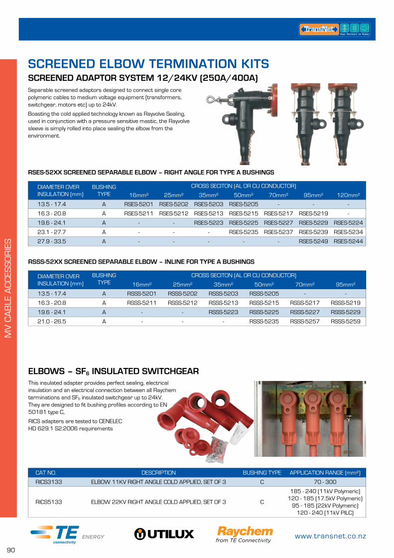
www.transnet.co.nz
90
MV
CA
BLE
AC
CES
SO
RIE
S
Separable screened adaptors designed to connect single core polymeric cables to medium voltage equipment (transformers, switchgear, motors etc) up to 24kV.
Boasting the cold applied technology known as Rayvolve Sealing, used in conjunction with a pressure sensitive mastic, the Rayvolve sleeve is simply rolled into place sealing the elbow from the environment.
SCREENED ELBOW TERMINATION KITS
DIAMETER OVER INSULATION (mm)
BUSHING TYPE
CROSS SECITON (AL OR CU CONDUCTOR)
16mm² 25mm² 35mm² 50mm² 70mm² 95mm² 120mm²
13.5 - 17.4 A RSES-5201 RSES-5202 RSES-5203 RSES-5205 - - -
16.3 - 20.8 A RSES-5211 RSES-5212 RSES-5213 RSES-5215 RSES-5217 RSES-5219 -
19.6 - 24.1 A - - RSES-5223 RSES-5225 RSES-5227 RSES-5229 RSES-5224
23.1 - 27.7 A - - - RSES-5235 RSES-5237 RSES-5239 RSES-5234
27.9 - 33.5 A - - - - - RSES-5249 RSES-5244
DIAMETER OVER INSULATION (mm)
BUSHING TYPE
CROSS SECITON (AL OR CU CONDUCTOR)
16mm² 25mm² 35mm² 50mm² 70mm² 95mm²
13.5 - 17.4 A RSSS-5201 RSSS-5202 RSSS-5203 RSSS-5205 - -
16.3 - 20.8 A RSSS-5211 RSSS-5212 RSSS-5213 RSSS-5215 RSSS-5217 RSSS-5219
19.6 - 24.1 A - - RSSS-5223 RSSS-5225 RSSS-5227 RSSS-5229
21.0 - 26.5 A - - - RSSS-5235 RSSS-5257 RSSS-5259
RSES-52XX SCREENED SEPARABLE ELBOW – RIGHT ANGLE FOR TYPE A BUSHINGS
RSSS-52XX SCREENED SEPARABLE ELBOW – INLINE FOR TYPE A BUSHINGS
This insulated adapter provides perfect sealing, electrical insulation and an electrical connection between all Raychem terminations and SF6 insulated switchgear up to 24kV. They are designed to fit bushing profiles according to EN 50181 type C,
RICS adapters are tested to CENELEC HD 629.1 S2:2006 requirements
ELBOWS – SF6 INSULATED SWITCHGEAR
CAT NO. DESCRIPTION BUSHING TYPE APPLICATION RANGE (mm²)
RICS3133 ELBOW 11KV RIGHT ANGLE COLD APPLIED, SET OF 3 C 70 - 300
RICS5133 ELBOW 22KV RIGHT ANGLE COLD APPLIED, SET OF 3 C
185 - 240 (11kV Polymeric)120 - 185 (17.5kV Polymeric)
95 - 185 (22kV Polymeric)120 - 240 (11kV PILC)
SCREENED ADAPTOR SYSTEM 12/24KV (250A/400A)

0800 442 182
91
MV
CA
BLE
AC
CES
SO
RIE
S
The Raychem RSTI family of screened separable elbows provide perfect sealing, electrical insulation and electrical connection to switchgear. The range offers solutions right up to 42kV with stand alone and piggy back elbows available should they be required.
Designed and tested to meet the requirements of all applicable international standards.
ELBOWS - SCREENED SEPARABLE ELBOW CONNECTION SYSTEM
CAT NO. ELBOW TYPECROSS SECTION
(mm²)CORE INSULATION DIAMETER (mm²)
VOLTAGE CLASS (kV)
BUSHING TYPE
RSTI-5810
STAND ALONE
25 (AL) 12.7 - 25.0
11/22 C1/C2
RSTI-5830 25 (CU) 12.7 - 25.0
RSTI-5851 35 - 95 12.7 - 25.0
RSTI-5852 95 - 150 12.7 - 25.0
RSTI-5853 95 - 185 17.0 - 32.6
RSTI-5854 95 - 240 21.3 - 34.6
RSTI-5855 185 - 300 21.3 - 34.6
RSTI-CC-5851
PIGGY BACK
35 - 95 12.7 - 25.0
11/22 C1/C2RSTI-CC-5852 95 - 120 12.7 - 25.0
RSTI-CC-5853 95 - 240 17.0 - 32.6
RSTI-CC-5855 185 - 300 21.3 - 34.6
RSTI-3951
STAND ALONE
400 28.9 - 36.4
11 C1/C2RSTI-3952 500 28.9 - 36.4
RSTI-3953 630 34.0 - 45.4
RSTI-3954 800 34.0 - 45.4
RSTI-CC-3953 PIGGY BACK 630 34.0 - 45.4 11 C1/C2
RSTI-5951
STAND ALONE
400 34.0 - 45.4
22 C1/C2RSTI-5952 500 34.0 - 45.4
RSTI-5953 630 39.1 - 59.0
RSTI-5954 800 39.1 - 59.0
RSTI-CC-5951PIGGY BACK
400 34.0 - 45.422 C1/C2
RSTI-CC-5954 800 39.1 - 59.0
RSTI-6851
STAND ALONE
35-95 22.4–35.5
33 C1/C2
RSTI-6852 95-150 22.4–35.5
RSTI-6853 120-240 28.9–42.0
RSTI-6855 158-300 28.9–42.0
RSTI-6856 240-400 28.9–42.0
RSTI-CC-6851
PIGGY BACK
35 - 95 22.4 - 35.5
33 C1/C2RSTI-CC-6853 150 - 240 28.9 - 42.0
RSTI-CC-6855 300 28.9 - 42.0
RSTI-6951
STAND ALONE
400 34.0–45.4
33 C1/C2RSTI-6952 500-630 39.1–59.0
RSTI-6953 800 31.9–59.0
RSTI-CC-6952PIGGY BACK
500 - 630 39.1 - 59.033 C1/C2
RSTI-CC-6953 800 39.1 - 59.0
NOTESC1 Bushings are rated at 630AC2 Bushings are rated at 1250AMaximum current through RSTI elbows is 800A each
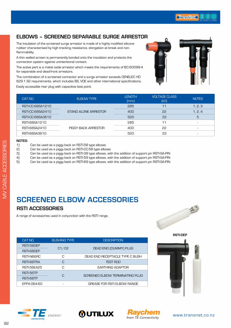
www.transnet.co.nz
92
RSTI-DEP
MV
CA
BLE
AC
CES
SO
RIE
S
A range of accessories used in conjunction with the RSTI range.
CAT NO. ELBOW TYPELENGTH
(mm)VOLTAGE CLASS
(kV)NOTES
RSTI-CC-68SA1210
STAND ALONE ARRESTOR
285 11 1, 2, 3
RSTI-CC-68SA2410 400 22 1, 2, 4
RSTI-CC-68SA3610 520 33 5
RSTI-68SA1210
PIGGY BACK ARRESTOR
285 11 -
RSTI-68SA2410 400 22 -
RSTI-68SA3610 520 33 -
CAT NO. BUSHING TYPE DESCRIPTION
RSTI-58DEPC1/C2 DEAD END (DUMMY) PLUG
RSTI-68DEP
RSTI-N66RC C DEAD END RECEPTACLE TYPE C BUSH
RSTI-68TRA C TEST ROD
RSTI-56EA25 C EARTHING ADAPTOR
RSTI-56TPC SCREENED ELBOW TERMINATING PLUG
RSTI-68TP
EPPA-064-60 - GREASE FOR RSTI ELBOW RANGE
NOTES:1) Can be used as a piggy back on RSTI-58 type elbows2) Can be used as a piggy back on RSTI-CC-58 type elbows3) Can be used as a piggy back on RSTI-39 type elbows, with the addition of support pin RSTI-SA-PIN4) Can be used as a piggy back on RSTI-59 type elbows, with the addition of support pin RSTI-SA-PIN5) Can be used as a piggy back on RSTI-69 type elbows, with the addition of support pin RSTI-SA-PIN
ELBOWS – SCREENED SEPARABLE SURGE ARRESTOR
RSTI ACCESSORIES
SCREENED ELBOW ACCESSORIES
The insulation of the screened surge arrestor is made of a highly modified silicone rubber characterised by high tracking resistance, elongation at break and non-flammability.
A thin walled screen is permanently bonded onto the insulation and protects the connection system against unintentional contact.
The active part is a metal oxide arrestor which meets the requirements of IEC-60099-4 for separable and dead-front arrestors.
The combination of a screened connector and a surge arrestor exceeds CENELEC HD 629.1 S2 requirements, which includes BS, VDE and other international specifications.
Easily accessible rear plug with capacitive test point.
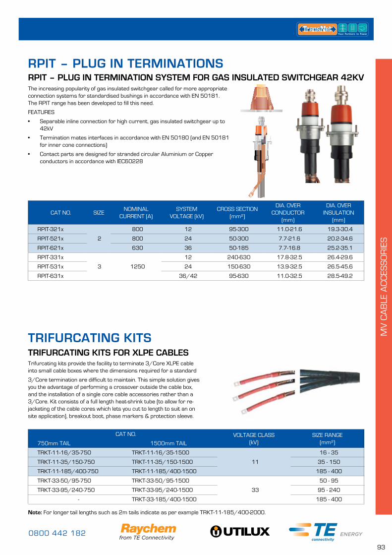
0800 442 182
93
MV
CA
BLE
AC
CES
SO
RIE
S
RPIT – PLUG IN TERMINATION SYSTEM FOR GAS INSULATED SWITCHGEAR 42KV
CAT NO. SIZENOMINAL
CURRENT (A)SYSTEM
VOLTAGE (kV)CROSS SECTION
(mm²)
DIA. OVER CONDUCTOR
(mm)
DIA. OVER INSULATION
(mm)
RPIT-321x
2
800 12 95-300 11.0-21.6 19.3-30.4
RPIT-521x 800 24 50-300 7.7-21.6 20.2-34.6
RPIT-621x 630 36 50-185 7.7-16.8 25.2-35.1
RPIT-331x
3 1250
12 240-630 17.8-32.5 26.4-29.6
RPIT-531x 24 150-630 13.9-32.5 26.5-45.6
RPIT-631x 36/42 95-630 11.0-32.5 28.5-49.2
The increasing popularity of gas insulated switchgear called for more appropriate connection systems for standardised bushings in accordance with EN 50181. The RPIT range has been developed to fill this need.
FEATURES
• Separable inline connection for high current, gas insulated switchgear up to 42kV
• Termination mates interfaces in accordance with EN 50180 (and EN 50181 for inner cone connections)
• Contact parts are designed for stranded circular Aluminium or Copper conductors in accordance with IEC60228
RPIT – PLUG IN TERMINATIONS
TRIFURCATING KITS FOR XLPE CABLES
CAT NO. VOLTAGE CLASS (kV)
SIZE RANGE (mm²)750mm TAIL 1500mm TAIL
TRKT-11-16/35-750 TRKT-11-16/35-1500
11
16 - 35
TRKT-11-35/150-750 TRKT-11-35/150-1500 35 - 150
TRKT-11-185/400-750 TRKT-11-185/400-1500 185 - 400
TRKT-33-50/95-750 TRKT-33-50/95-1500
33
50 - 95
TRKT-33-95/240-750 TRKT-33-95/240-1500 95 - 240
- TRKT-33-185/400-1500 185 - 400
Note: For longer tail lengths such as 2m tails indicate as per example TRKT-11-185/400-2000.
Trifurcating kits provide the facility to terminate 3/Core XLPE cable into small cable boxes where the dimensions required for a standard
3/Core termination are difficult to maintain. This simple solution gives you the advantage of performing a crossover outside the cable box, and the installation of a single core cable accessories rather than a 3/Core. Kit consists of a full length heat-shrink tube (to allow for re-jacketing of the cable cores which lets you cut to length to suit an on site application), breakout boot, phase markers & protection sleeve.
TRIFURCATING KITS
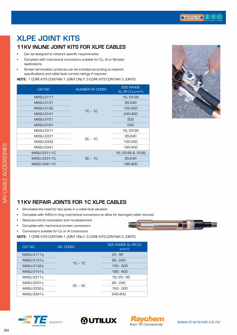
www.transnet.co.nz
94
MV
CA
BLE
AC
CES
SO
RIE
S
• Can be designed to network specific requirements
• Complete with mechanical connectors suitable for Cu, Al or Bimetal applications
• Screen termination products can be included according to network specifications and cable fault current ratings if required
NOTE: 1 CORE KITS CONTAIN 1 JOINT ONLY, 3 CORE KITS CONTAIN 3 JOINTS
11KV INLINE JOINT KITS FOR XLPE CABLES
CAT NO. NUMBER OF CORESSIZE RANGE
AL OR CU (mm²)
MXSU-3111
1C – 1C
16/25-95
MXSU-3131 95-240
MXSU-3132 150-300
MXSU-3141 240-400
MXSU-3151 500
MXSU-3161 630
MXSU-3311
3C – 1C
16/25-95
MXSU-3331 95-240
MXSU-3332 150-300
MXSU-3341 185-400
MXSU-3311-1C
3C – 1C
16/25-95 & 16-95
MXSU-3331-1C 95-240
MXSU-3341-1C 185-400
CAT NO. NO. CORESSIZE RANGE AL OR CU
(mm²)
MXSU-3111-L
1C – 1C
25 - 95
MXSU-3131-L 95 - 240
MXSU-3132-L 150 - 300
MXSU-3141-L 185 - 400
MXSU-3311-L
3C – 3C
16/25 - 95
MXSU-3331-L 95 - 240
MXSU-3332-L 150 - 300
MXSU-3341-L 240-400
11KV REPAIR JOINTS FOR 1C XLPE CABLES• Eliminates the need for two joints in a cable fault situation
• Complete with 440mm long mechanical connectors to allow for damaged cable removal
• Reduces trench excavation and re-instatement
• Complete with mechanical screen connectors
• Connectors suitable for Cu or Al conductors
NOTE: 1 CORE KITS CONTAIN 1 JOINT ONLY, 3 CORE KITS CONTAIN 3 JOINTS
XLPE JOINT KITS
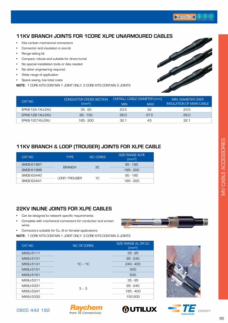
0800 442 182
95
MV
CA
BLE
AC
CES
SO
RIE
S
CAT NO.CONDUCTOR CROSS SECTION
(mm²)OVERALL CABLE DIAMETER (mm) MIN. DIAMETER OVER
INSULATION OF MAIN CABLEMIN MAX
EPKB-12A-1XU-2XU 35 - 95 23.5 32 23.5
EPKB-12B-1XU-2XU 95 - 150 26.0 37.5 26.0
EPKB-12C1XU-2XU 185 - 300 32.1 43 32.1
11KV BRANCH JOINTS FOR 1CORE XLPE UNARMOURED CABLES• Kits contain mechanical connectors
• Connector and insulation in one kit
• Range taking kit
• Compact, robust and suitable for direct burial
• No special installation tools or dies needed
• No other engineering required
• Wide range of application
• Space saving, low total costs
NOTE: 1 CORE KITS CONTAIN 1 JOINT ONLY, 3 CORE KITS CONTAIN 3 JOINTS
CAT NO. TYPE NO. CORESSIZE RANGE XLPE
(mm²)
SMOE-61987BRANCH 3C
95 - 185
SMOE-61988 185 - 300
SMOE-63440LOOP/TROUSER 1C
95 - 185
SMOE-63441 185 - 300
11KV BRANCH & LOOP (TROUSER) JOINTS FOR XLPE CABLE
22KV INLINE JOINTS FOR XLPE CABLES
CAT NO. NO. OF CORESSIZE RANGE AL OR CU
(mm²)
MXSU-5111
1C – 1C
35 - 95
MXSU-5131 95 - 240
MXSU-5141 240 - 400
MXSU-5151 500
MXSU-5161 630
MXSU-5311
3 – 3
35 - 95
MXSU-5331 95 - 240
MXSU-5341 185 - 400
MXSU-5332 150-300
• Can be designed to network specific requirements
• Complete with mechanical connectors for conductor and screen wires
• Connectors suitable for Cu, Al or bimetal applications
NOTE: 1 CORE KITS CONTAIN 1 JOINT ONLY, 3 CORE KITS CONTAIN 3 JOINTS
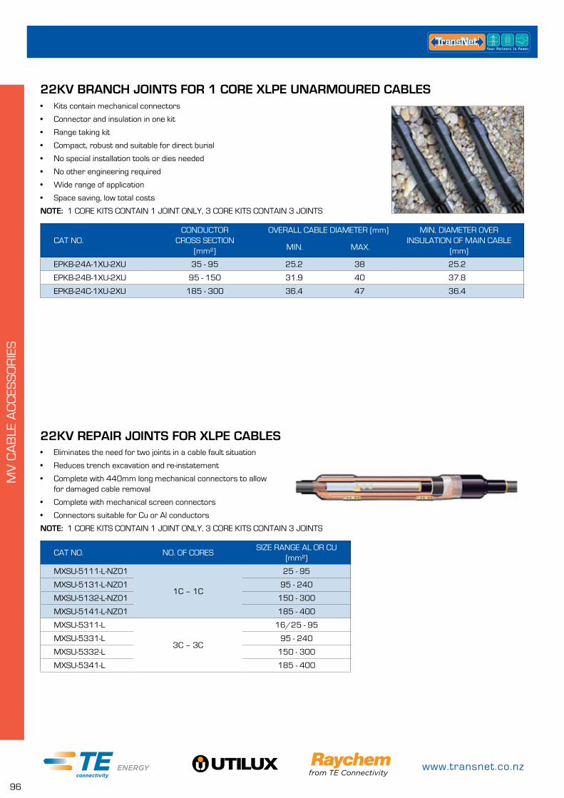
www.transnet.co.nz
96
MV
CA
BLE
AC
CES
SO
RIE
S
22KV BRANCH JOINTS FOR 1 CORE XLPE UNARMOURED CABLES
CAT NO.CONDUCTOR
CROSS SECTION (mm²)
OVERALL CABLE DIAMETER (mm) MIN, DIAMETER OVER INSULATION OF MAIN CABLE
(mm)MIN. MAX.
EPKB-24A-1XU-2XU 35 - 95 25.2 38 25.2
EPKB-24B-1XU-2XU 95 - 150 31.9 40 37.8
EPKB-24C-1XU-2XU 185 - 300 36.4 47 36.4
• Kits contain mechanical connectors
• Connector and insulation in one kit
• Range taking kit
• Compact, robust and suitable for direct burial
• No special installation tools or dies needed
• No other engineering required
• Wide range of application
• Space saving, low total costs
NOTE: 1 CORE KITS CONTAIN 1 JOINT ONLY, 3 CORE KITS CONTAIN 3 JOINTS
22KV REPAIR JOINTS FOR XLPE CABLES
CAT NO. NO. OF CORESSIZE RANGE AL OR CU
(mm²)
MXSU-5111-L-NZ01
1C – 1C
25 - 95
MXSU-5131-L-NZ01 95 - 240
MXSU-5132-L-NZ01 150 - 300
MXSU-5141-L-NZ01 185 - 400
MXSU-5311-L
3C – 3C
16/25 - 95
MXSU-5331-L 95 - 240
MXSU-5332-L 150 - 300
MXSU-5341-L 185 - 400
• Eliminates the need for two joints in a cable fault situation
• Reduces trench excavation and re-instatement
• Complete with 440mm long mechanical connectors to allow for damaged cable removal
• Complete with mechanical screen connectors
• Connectors suitable for Cu or Al conductors
NOTE: 1 CORE KITS CONTAIN 1 JOINT ONLY, 3 CORE KITS CONTAIN 3 JOINTS
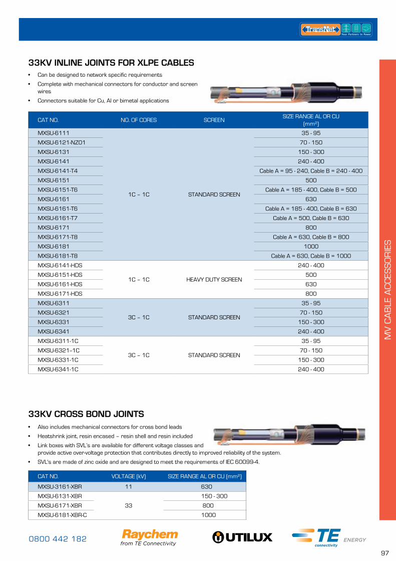
0800 442 182
97
MV
CA
BLE
AC
CES
SO
RIE
S
33KV INLINE JOINTS FOR XLPE CABLES
CAT NO. NO. OF CORES SCREENSIZE RANGE AL OR CU
(mm²)
MXSU-6111
1C – 1C STANDARD SCREEN
35 - 95
MXSU-6121-NZ01 70 - 150
MXSU-6131 150 - 300
MXSU-6141 240 - 400
MXSU-6141-T4 Cable A = 95 - 240, Cable B = 240 - 400
MXSU-6151 500
MXSU-6151-T6 Cable A = 185 - 400, Cable B = 500
MXSU-6161 630
MXSU-6161-T6 Cable A = 185 - 400, Cable B = 630
MXSU-6161-T7 Cable A = 500, Cable B = 630
MXSU-6171 800
MXSU-6171-T8 Cable A = 630, Cable B = 800
MXSU-6181 1000
MXSU-6181-T8 Cable A = 630, Cable B = 1000
MXSU-6141-HDS
1C – 1C HEAVY DUTY SCREEN
240 - 400
MXSU-6151-HDS 500
MXSU-6161-HDS 630
MXSU-6171-HDS 800
MXSU-6311
3C – 1C STANDARD SCREEN
35 - 95
MXSU-6321 70 - 150
MXSU-6331 150 - 300
MXSU-6341 240 - 400
MXSU-6311-1C
3C – 1C STANDARD SCREEN
35 - 95
MXSU-6321--1C 70 - 150
MXSU-6331-1C 150 - 300
MXSU-6341-1C 240 - 400
• Can be designed to network specific requirements
• Complete with mechanical connectors for conductor and screen wires
• Connectors suitable for Cu, Al or bimetal applications
33KV CROSS BOND JOINTS
CAT NO. VOLTAGE (kV) SIZE RANGE AL OR CU (mm²)
MXSU-3161-XBR 11 630
MXSU-6131-XBR
33
150 - 300
MXSU-6171-XBR 800
MXSU-6181-XBR-C 1000
• Also includes mechanical connectors for cross bond leads
• Heatshrink joint, resin encased – resin shell and resin included
• Link boxes with SVL’s are available for different voltage classes and provide active over-voltage protection that contributes directly to improved reliability of the system.
• SVL's are made of zinc oxide and are designed to meet the requirements of IEC 60099-4.
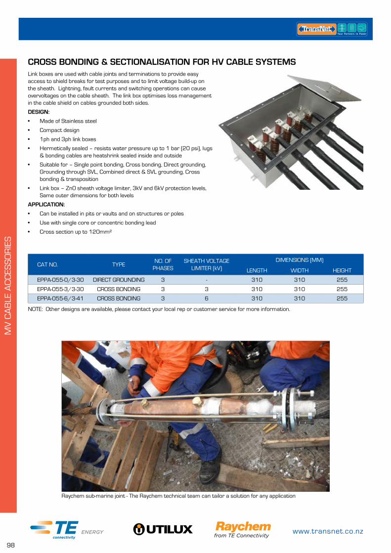
www.transnet.co.nz
98
MV
CA
BLE
AC
CES
SO
RIE
S
CAT NO. TYPENO. OF
PHASESSHEATH VOLTAGE
LIMITER (kV)DIMENSIONS (MM)
LENGTH WIDTH HEIGHT
EPPA-055-0/3-30 DIRECT GROUNDING 3 - 310 310 255
EPPA-055-3/3-30 CROSS BONDING 3 3 310 310 255
EPPA-055-6/3-41 CROSS BONDING 3 6 310 310 255
CROSS BONDING & SECTIONALISATION FOR HV CABLE SYSTEMSLink boxes are used with cable joints and terminations to provide easy access to shield breaks for test purposes and to limit voltage build-up on the sheath. Lightning, fault currents and switching operations can cause overvoltages on the cable sheath. The link box optimises loss management in the cable shield on cables grounded both sides.
DESIGN:
• Made of Stainless steel
• Compact design
• 1ph and 3ph link boxes
• Hermetically sealed – resists water pressure up to 1 bar (20 psi), lugs & bonding cables are heatshrink sealed inside and outside
• Suitable for – Single point bonding, Cross bonding, Direct grounding, Grounding through SVL, Combined direct & SVL grounding, Cross bonding & transposition
• Link box – Zn0 sheath voltage limiter, 3kV and 6kV protection levels, Same outer dimensions for both levels
APPLICATION:
• Can be installed in pits or vaults and on structures or poles
• Use with single core or concentric bonding lead
• Cross section up to 120mm²
NOTE: Other designs are available, please contact your local rep or customer service for more information.
Raychem sub-marine joint - The Raychem technical team can tailor a solution for any application
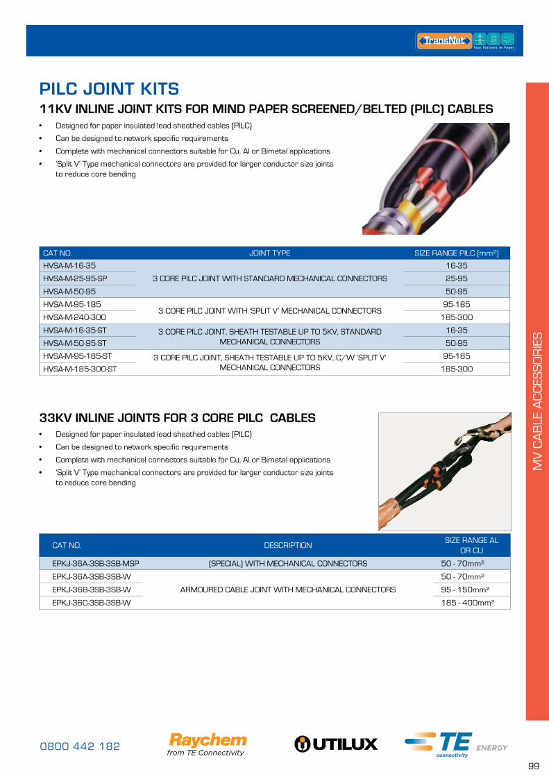
0800 442 182
99
MV
CA
BLE
AC
CES
SO
RIE
S
• Designed for paper insulated lead sheathed cables (PILC)
• Can be designed to network specific requirements
• Complete with mechanical connectors suitable for Cu, Al or Bimetal applications
• ‘Split V’ Type mechanical connectors are provided for larger conductor size joints to reduce core bending
11KV INLINE JOINT KITS FOR MIND PAPER SCREENED/BELTED (PILC) CABLES
CAT NO. JOINT TYPE SIZE RANGE PILC (mm²)
HVSA-M-16-35
3 CORE PILC JOINT WITH STANDARD MECHANICAL CONNECTORS
16-35
HVSA-M-25-95-SP 25-95
HVSA-M-50-95 50-95
HVSA-M-95-1853 CORE PILC JOINT WITH ‘SPLIT V’ MECHANICAL CONNECTORS
95-185
HVSA-M-240-300 185-300
HVSA-M-16-35-ST 3 CORE PILC JOINT, SHEATH TESTABLE UP TO 5KV, STANDARD MECHANICAL CONNECTORS
16-35
HVSA-M-50-95-ST 50-95
HVSA-M-95-185-ST 3 CORE PILC JOINT, SHEATH TESTABLE UP TO 5KV, C/W ‘SPLIT V’ MECHANICAL CONNECTORS
95-185
HVSA-M-185-300-ST 185-300
PILC JOINT KITS
CAT NO. DESCRIPTIONSIZE RANGE AL
OR CU
EPKJ-36A-3SB-3SB-MSP (SPECIAL) WITH MECHANICAL CONNECTORS 50 - 70mm²
EPKJ-36A-3SB-3SB-W
ARMOURED CABLE JOINT WITH MECHANICAL CONNECTORS
50 - 70mm²
EPKJ-36B-3SB-3SB-W 95 - 150mm²
EPKJ-36C-3SB-3SB-W 185 - 400mm²
33KV INLINE JOINTS FOR 3 CORE PILC CABLES• Designed for paper insulated lead sheathed cables (PILC)
• Can be designed to network specific requirements
• Complete with mechanical connectors suitable for Cu, Al or Bimetal applications
• ‘Split V’ Type mechanical connectors are provided for larger conductor size joints to reduce core bending
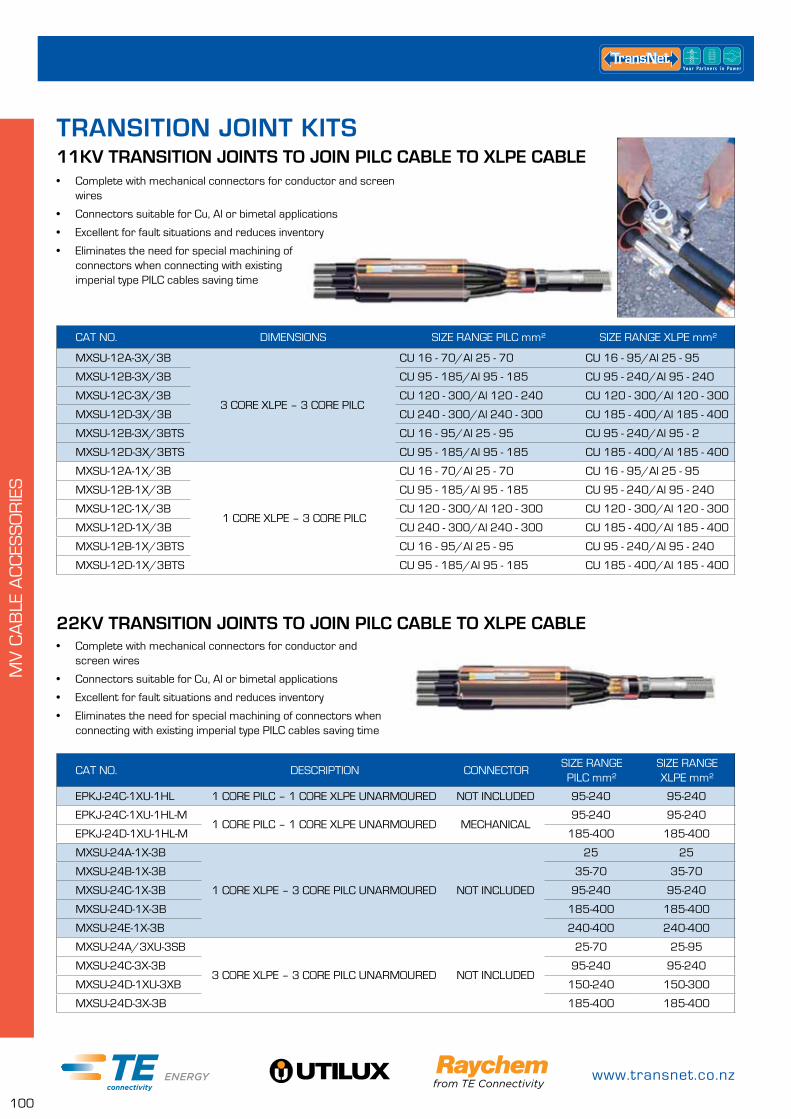
www.transnet.co.nz
100
MV
CA
BLE
AC
CES
SO
RIE
S
TRANSITION JOINT KITS
CAT NO. DIMENSIONS SIZE RANGE PILC mm² SIZE RANGE XLPE mm²
MXSU-12A-3X/3B
3 CORE XLPE – 3 CORE PILC
CU 16 - 70/Al 25 - 70 CU 16 - 95/Al 25 - 95
MXSU-12B-3X/3B CU 95 - 185/Al 95 - 185 CU 95 - 240/Al 95 - 240
MXSU-12C-3X/3B CU 120 - 300/Al 120 - 240 CU 120 - 300/Al 120 - 300
MXSU-12D-3X/3B CU 240 - 300/Al 240 - 300 CU 185 - 400/Al 185 - 400
MXSU-12B-3X/3BTS CU 16 - 95/Al 25 - 95 CU 95 - 240/Al 95 - 2
MXSU-12D-3X/3BTS CU 95 - 185/Al 95 - 185 CU 185 - 400/Al 185 - 400
MXSU-12A-1X/3B
1 CORE XLPE – 3 CORE PILC
CU 16 - 70/Al 25 - 70 CU 16 - 95/Al 25 - 95
MXSU-12B-1X/3B CU 95 - 185/Al 95 - 185 CU 95 - 240/Al 95 - 240
MXSU-12C-1X/3B CU 120 - 300/Al 120 - 300 CU 120 - 300/Al 120 - 300
MXSU-12D-1X/3B CU 240 - 300/Al 240 - 300 CU 185 - 400/Al 185 - 400
MXSU-12B-1X/3BTS CU 16 - 95/Al 25 - 95 CU 95 - 240/Al 95 - 240
MXSU-12D-1X/3BTS CU 95 - 185/Al 95 - 185 CU 185 - 400/Al 185 - 400
11KV TRANSITION JOINTS TO JOIN PILC CABLE TO XLPE CABLE• Complete with mechanical connectors for conductor and screen
wires
• Connectors suitable for Cu, Al or bimetal applications
• Excellent for fault situations and reduces inventory
• Eliminates the need for special machining of connectors when connecting with existing imperial type PILC cables saving time
CAT NO. DESCRIPTION CONNECTORSIZE RANGE PILC mm²
SIZE RANGE XLPE mm²
EPKJ-24C-1XU-1HL 1 CORE PILC – 1 CORE XLPE UNARMOURED NOT INCLUDED 95-240 95-240
EPKJ-24C-1XU-1HL-M1 CORE PILC – 1 CORE XLPE UNARMOURED MECHANICAL
95-240 95-240
EPKJ-24D-1XU-1HL-M 185-400 185-400
MXSU-24A-1X-3B
1 CORE XLPE – 3 CORE PILC UNARMOURED NOT INCLUDED
25 25
MXSU-24B-1X-3B 35-70 35-70
MXSU-24C-1X-3B 95-240 95-240
MXSU-24D-1X-3B 185-400 185-400
MXSU-24E-1X-3B 240-400 240-400
MXSU-24A/3XU-3SB
3 CORE XLPE – 3 CORE PILC UNARMOURED NOT INCLUDED
25-70 25-95
MXSU-24C-3X-3B 95-240 95-240
MXSU-24D-1XU-3XB 150-240 150-300
MXSU-24D-3X-3B 185-400 185-400
22KV TRANSITION JOINTS TO JOIN PILC CABLE TO XLPE CABLE• Complete with mechanical connectors for conductor and
screen wires
• Connectors suitable for Cu, Al or bimetal applications
• Excellent for fault situations and reduces inventory
• Eliminates the need for special machining of connectors when connecting with existing imperial type PILC cables saving time
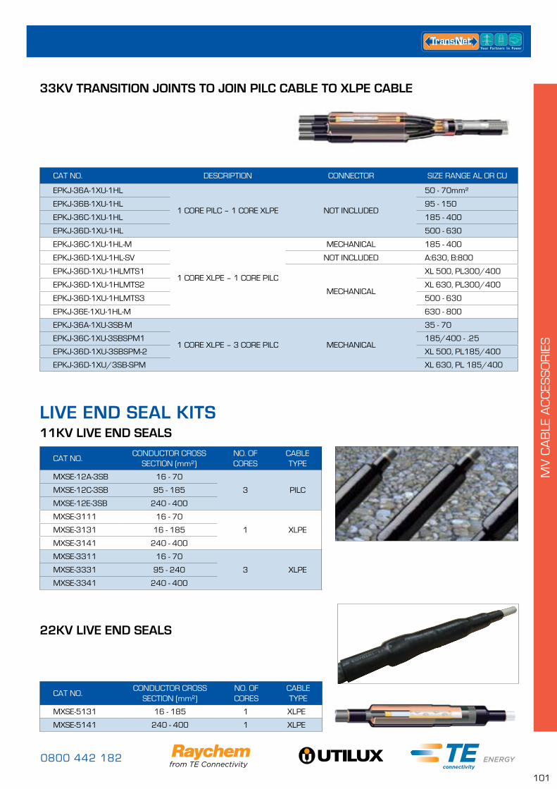
0800 442 182
101
MV
CA
BLE
AC
CES
SO
RIE
S
CAT NO. DESCRIPTION CONNECTOR SIZE RANGE AL OR CU
EPKJ-36A-1XU-1HL
1 CORE PILC – 1 CORE XLPE NOT INCLUDED
50 - 70mm²
EPKJ-36B-1XU-1HL 95 - 150
EPKJ-36C-1XU-1HL 185 - 400
EPKJ-36D-1XU-1HL 500 - 630
EPKJ-36C-1XU-1HL-M
1 CORE XLPE – 1 CORE PILC
MECHANICAL 185 - 400
EPKJ-36D-1XU-1HL-SV NOT INCLUDED A:630, B:800
EPKJ-36D-1XU-1HLMTS1
MECHANICAL
XL 500, PL300/400
EPKJ-36D-1XU-1HLMTS2 XL 630, PL300/400
EPKJ-36D-1XU-1HLMTS3 500 - 630
EPKJ-36E-1XU-1HL-M 630 - 800
EPKJ-36A-1XU-3SB-M
1 CORE XLPE – 3 CORE PILC MECHANICAL
35 - 70
EPKJ-36C-1XU-3SBSPM1 185/400 - .25
EPKJ-36D-1XU-3SBSPM-2 XL 500, PL185/400
EPKJ-36D-1XU/3SB-SPM XL 630, PL 185/400
33KV TRANSITION JOINTS TO JOIN PILC CABLE TO XLPE CABLE
CAT NO.CONDUCTOR CROSS
SECTION (mm²)NO. OF CORES
CABLE TYPE
MXSE-12A-3SB 16 - 70
3 PILCMXSE-12C-3SB 95 - 185
MXSE-12E-3SB 240 - 400
MXSE-3111 16 - 70
1 XLPEMXSE-3131 16 - 185
MXSE-3141 240 - 400
MXSE-3311 16 - 70
3 XLPEMXSE-3331 95 - 240
MXSE-3341 240 - 400
11KV LIVE END SEALS
22KV LIVE END SEALS
CAT NO. CONDUCTOR CROSS
SECTION (mm²)NO. OF CORES
CABLE TYPE
MXSE-5131 16 - 185 1 XLPE
MXSE-5141 240 - 400 1 XLPE
LIVE END SEAL KITS

www.transnet.co.nz
102
MV
CA
BLE
AC
CES
SO
RIE
S
CABLE JOINTING TOOLSGENERAL JOINTING TOOLS
CAT NO. EXRM-0607Knife and Scabbard
CAT NO. LE-325Heavy Duty Work Knife in Holster with safety lock, belt loop & sharpener. 234mm long (80mm blade)
CAT NO. 503 1000V rated Cable Stripping Knife
CAT NO. GT/F00182Footprint brand Jointers Hack Knife
CAT NO. IT/120-CSPolymeric Hack Knife
CAT NO. IT/120-CSPolymeric Hack Knife
CAT NO. IT/HSO1810 1000V Insulated Junior Hacksaw
CAT NO. IT/HSO1820 1000V Insulated 12” Hacksaw

0800 442 182
103
MV
CA
BLE
AC
CES
SO
RIE
S
CAT NO. 128-290 1000V Insulated Ratchet Cable Cutter, 185mm² Al, 150mm² Cu
CAT NO. 128-310 1000V Insulated Ratchet Cable Cutter, 240mm² Al/Cu
CAT NO. HRIPS Ripper Stripper
CAT NO. 116-240 1000V rated Waterpump Plier 240mm
CAT NO. IRW13-171000V Insulated Ratchet Spanner
CAT NO. 2231000V Insulated Mechanical Connector Holder
CAT NO. IT-1000-019 Mechanical Connector Holding Tool – Large
CAT NO. -2 1000V Insulated Reversible Ratchet 1/2” Drive
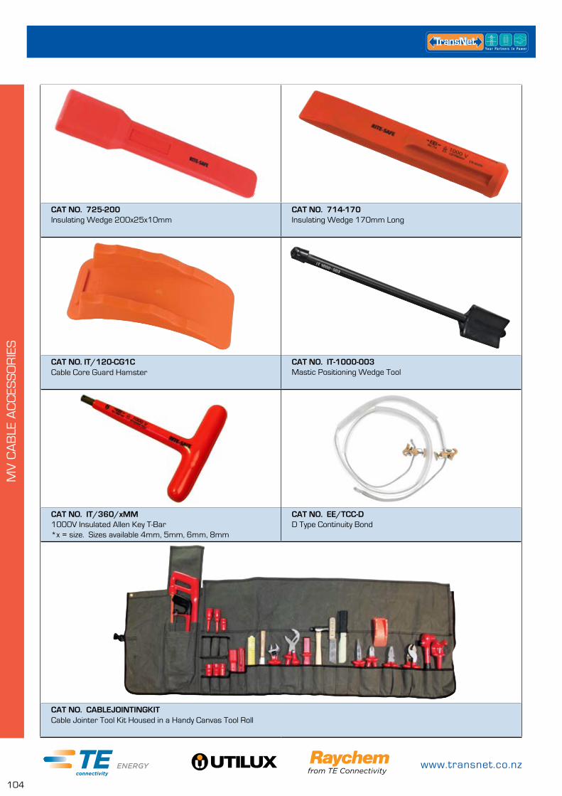
www.transnet.co.nz
104
MV
CA
BLE
AC
CES
SO
RIE
S
CAT NO. 725-200 Insulating Wedge 200x25x10mm
CAT NO. 714-170 Insulating Wedge 170mm Long
CAT NO. IT/120-CG1C Cable Core Guard Hamster
CAT NO. IT-1000-003 Mastic Positioning Wedge Tool
CAT NO. IT/360/xMM1000V Insulated Allen Key T-Bar*x = size. Sizes available 4mm, 5mm, 6mm, 8mm
CAT NO. EE/TCC-DD Type Continuity Bond
CAT NO. CABLEJOINTINGKIT Cable Jointer Tool Kit Housed in a Handy Canvas Tool Roll
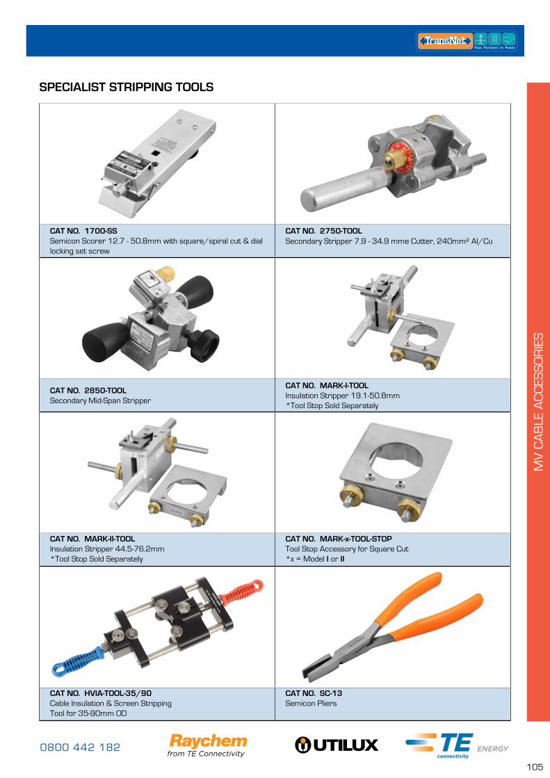
0800 442 182
105
MV
CA
BLE
AC
CES
SO
RIE
S
SPECIALIST STRIPPING TOOLS
CAT NO. 1700-SS Semicon Scorer 12.7 - 50.8mm with square/spiral cut & dial locking set screw
CAT NO. 2750-TOOL Secondary Stripper 7.9 - 34.9 mme Cutter, 240mm² Al/Cu
CAT NO. 2850-TOOL Secondary Mid-Span Stripper
CAT NO. MARK-I-TOOLInsulation Stripper 19.1-50.8mm *Tool Stop Sold Separately
CAT NO. MARK-II-TOOL Insulation Stripper 44.5-76.2mm *Tool Stop Sold Separately
CAT NO. MARK-x-TOOL-STOP Tool Stop Accessory for Square Cut *x = Model I or II
CAT NO. HVIA-TOOL-35/90 Cable Insulation & Screen Stripping Tool for 35-90mm OD
CAT NO. SC-13 Semicon Pliers
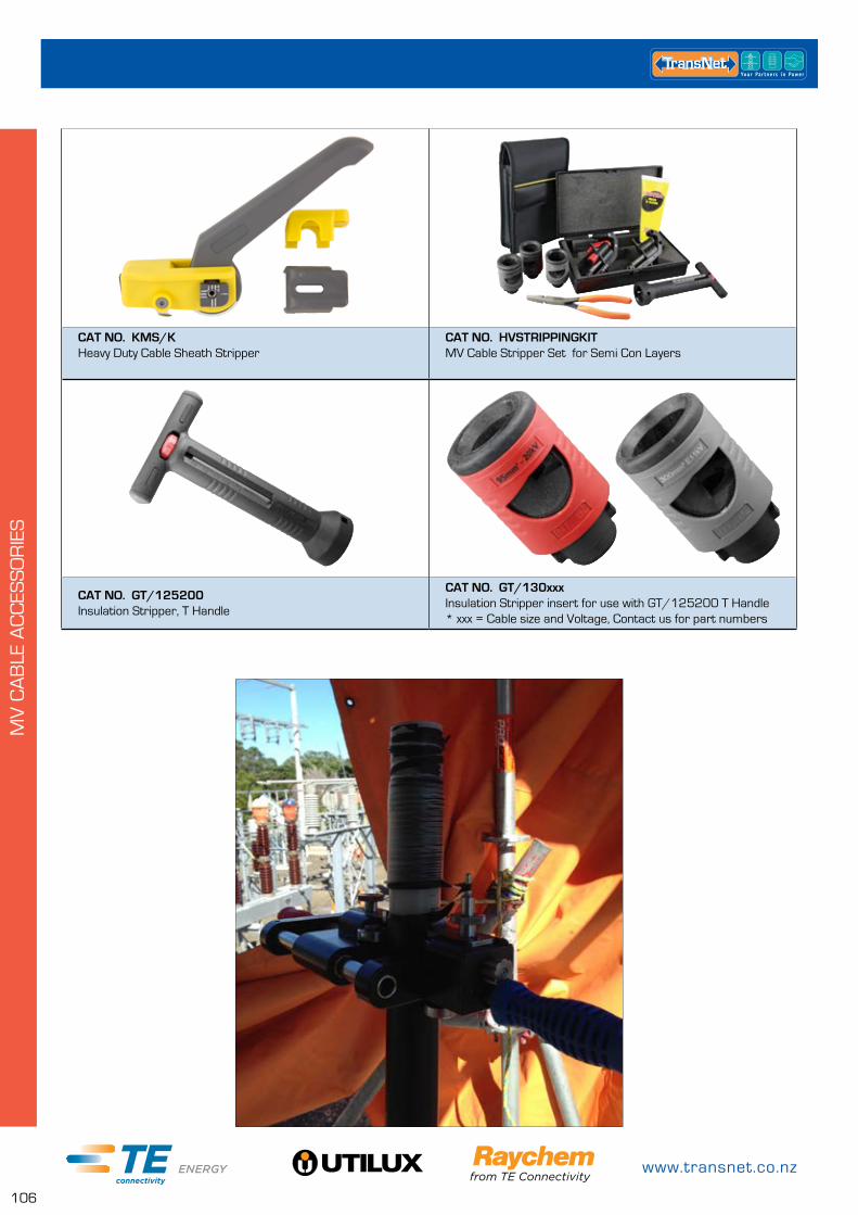
www.transnet.co.nz
106
MV
CA
BLE
AC
CES
SO
RIE
S
CAT NO. KMS/K Heavy Duty Cable Sheath Stripper
CAT NO. HVSTRIPPINGKIT MV Cable Stripper Set for Semi Con Layers
CAT NO. GT/125200 Insulation Stripper, T Handle
CAT NO. GT/130xxxInsulation Stripper insert for use with GT/125200 T Handle * xxx = Cable size and Voltage, Contact us for part numbers
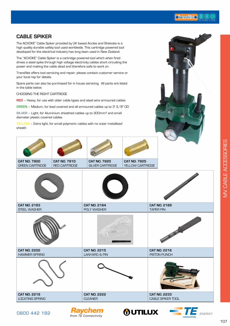
0800 442 182
107
MV
CA
BLE
AC
CES
SO
RIE
S
CABLE SPIKER
CAT NO. 2183 STEEL WASHER
CAT NO. 2184 POLY WASHER
CAT NO. 2189 TAPER PIN
CAT NO. 2202 HAMMER SPRING
CAT NO. 2215 LANYARD & PIN
CAT NO. 2216 PISTON PUNCH
CAT NO. 2218 LOCATING SPRING
CAT NO. 2222 CLEANER
CAT NO. 2233 CABLE SPIKER TOOL
CAT NO. 7900 GREEN CARTRIDGE
CAT NO. 7910 RED CARTRIDGE
CAT NO. 7920 SILVER CARTRIDGE
CAT NO. 7925 YELLOW CARTRIDGE
The ACVOKE” Cable Spiker provided by UK based Accles and Shelvoke is a high quality durable safety tool used worldwide. This cartridge powered tool developed for the electrical industry has long been used in New Zealand.
The “ACVOKE” Cable Spiker is a cartridge powered tool which when fired drives a steel spike through high voltage electricity cables short circuiting the power and making the cable dead and therefore safe to work on.
TransNet offers tool servicing and repair, please contact customer service or your local rep for details.
Spare parts can also be purchased for in house servicing. All parts are listed in the table below.
CHOOSING THE RIGHT CARTRIDGE
RED – Heavy, for use with older cable types and steel wire armoured cables
GREEN – Medium, for lead covered and all armoured cables up to 3' 3/8" OD
SILVER – Light, for Aluminium sheathed cables up to 300mm² and small diameter plastic covered cables
YELLOW – Extra light, for small polymeric cables with no outer metallised sheath

www.transnet.co.nz
108
MV
CA
BLE
AC
CES
SO
RIE
S
66KV RAYCHEM HEATSHRINK TERMINATION
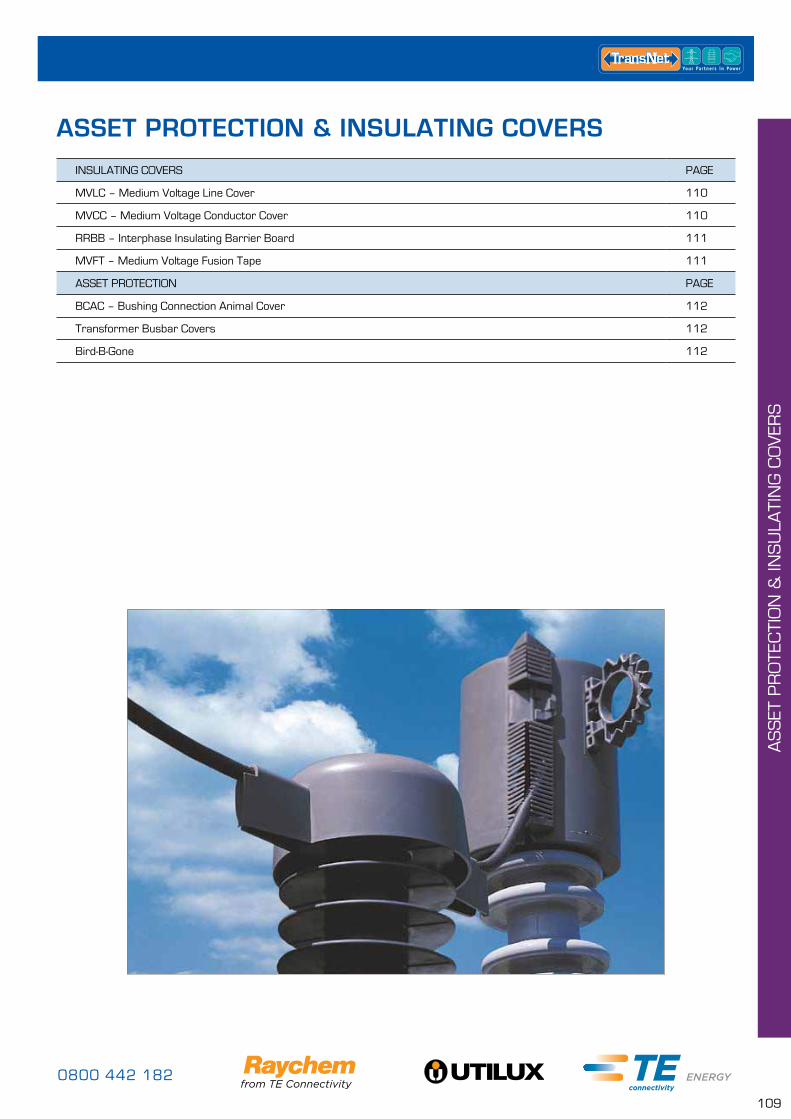
0800 442 182
109
AS
SET
PR
OTE
CTI
ON
& IN
SU
LATI
NG
CO
VER
S
INSULATING COVERS PAGE
MVLC – Medium Voltage Line Cover 110
MVCC – Medium Voltage Conductor Cover 110
RRBB – Interphase Insulating Barrier Board 111
MVFT – Medium Voltage Fusion Tape 111
ASSET PROTECTION PAGE
BCAC – Bushing Connection Animal Cover 112
Transformer Busbar Covers 112
Bird-B-Gone 112
ASSET PROTECTION & INSULATING COVERS
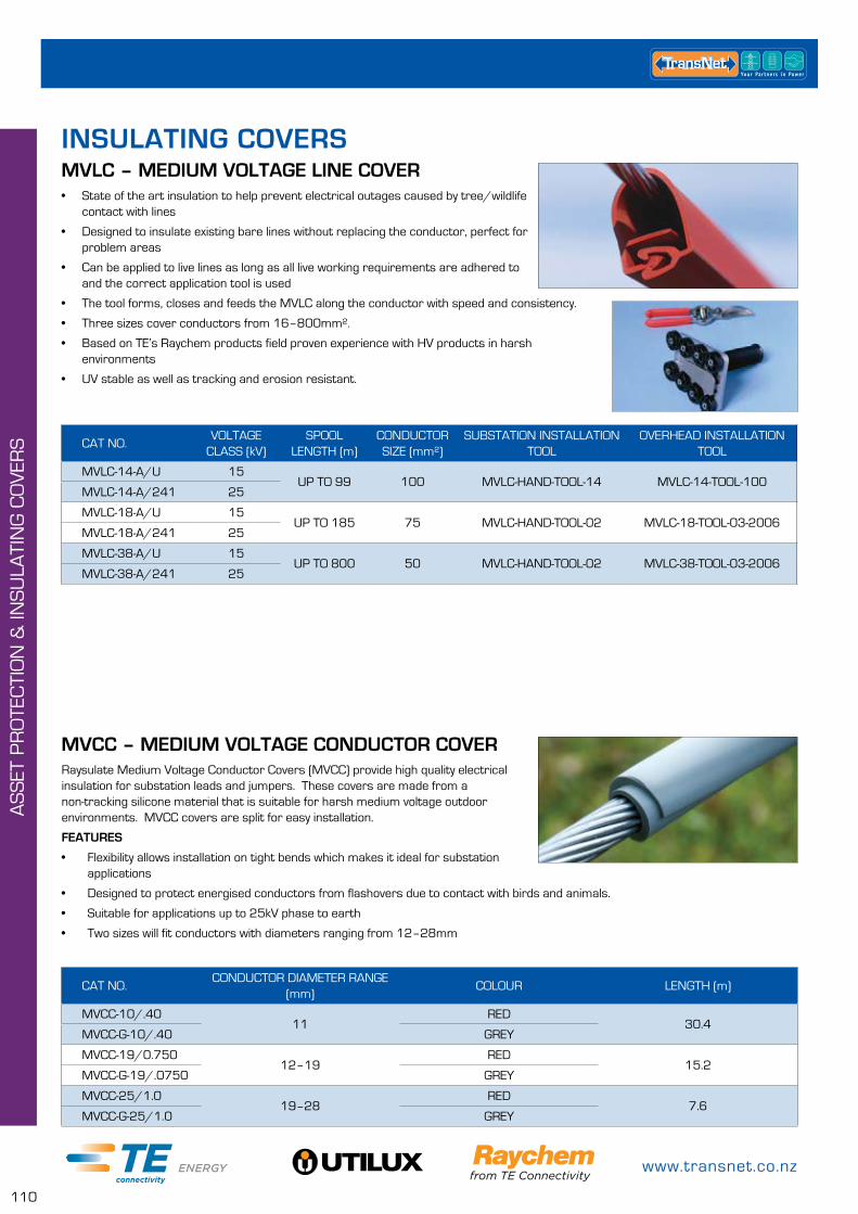
www.transnet.co.nz
110
AS
SET
PR
OTE
CTI
ON
& IN
SU
LATI
NG
CO
VER
S
MVLC – MEDIUM VOLTAGE LINE COVER
MVCC – MEDIUM VOLTAGE CONDUCTOR COVER
• State of the art insulation to help prevent electrical outages caused by tree/wildlife contact with lines
• Designed to insulate existing bare lines without replacing the conductor, perfect for problem areas
• Can be applied to live lines as long as all live working requirements are adhered to and the correct application tool is used
• The tool forms, closes and feeds the MVLC along the conductor with speed and consistency.
• Three sizes cover conductors from 16–800mm².
• Based on TE’s Raychem products field proven experience with HV products in harsh environments
• UV stable as well as tracking and erosion resistant.
Raysulate Medium Voltage Conductor Covers (MVCC) provide high quality electrical insulation for substation leads and jumpers. These covers are made from a non-tracking silicone material that is suitable for harsh medium voltage outdoor environments. MVCC covers are split for easy installation.
FEATURES
• Flexibility allows installation on tight bends which makes it ideal for substation applications
• Designed to protect energised conductors from flashovers due to contact with birds and animals.
• Suitable for applications up to 25kV phase to earth
• Two sizes will fit conductors with diameters ranging from 12–28mm
CAT NO.VOLTAGE
CLASS (kV)SPOOL
LENGTH (m)CONDUCTOR SIZE (mm²)
SUBSTATION INSTALLATION TOOL
OVERHEAD INSTALLATION TOOL
MVLC-14-A/U 15UP TO 99 100 MVLC-HAND-TOOL-14 MVLC-14-TOOL-100
MVLC-14-A/241 25
MVLC-18-A/U 15UP TO 185 75 MVLC-HAND-TOOL-02 MVLC-18-TOOL-03-2006
MVLC-18-A/241 25
MVLC-38-A/U 15UP TO 800 50 MVLC-HAND-TOOL-02 MVLC-38-TOOL-03-2006
MVLC-38-A/241 25
CAT NO.CONDUCTOR DIAMETER RANGE
(mm)COLOUR LENGTH (m)
MVCC-10/.4011
RED30.4
MVCC-G-10/.40 GREY
MVCC-19/0.75012–19
RED15.2
MVCC-G-19/.0750 GREY
MVCC-25/1.019–28
RED7.6
MVCC-G-25/1.0 GREY
INSULATING COVERS
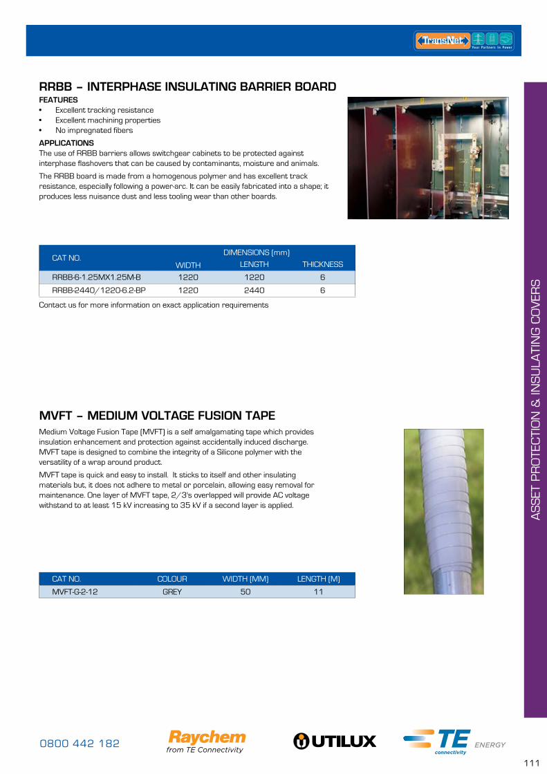
0800 442 182
111
RRBB – INTERPHASE INSULATING BARRIER BOARD
APPLICATIONSThe use of RRBB barriers allows switchgear cabinets to be protected against interphase flashovers that can be caused by contaminants, moisture and animals.
The RRBB board is made from a homogenous polymer and has excellent track resistance, especially following a power-arc. It can be easily fabricated into a shape; it produces less nuisance dust and less tooling wear than other boards.
FEATURES• Excellent tracking resistance• Excellent machining properties• No impregnated fibers
CAT NO.DIMENSIONS (mm)
WIDTH LENGTH THICKNESS
RRBB-6-1.25MX1.25M-B 1220 1220 6
RRBB-2440/1220-6.2-BP 1220 2440 6
Contact us for more information on exact application requirements
AS
SET
PR
OTE
CTI
ON
& IN
SU
LATI
NG
CO
VER
S
MVFT – MEDIUM VOLTAGE FUSION TAPEMedium Voltage Fusion Tape (MVFT) is a self amalgamating tape which provides insulation enhancement and protection against accidentally induced discharge. MVFT tape is designed to combine the integrity of a Silicone polymer with the versatility of a wrap around product.
MVFT tape is quick and easy to install. It sticks to itself and other insulating materials but, it does not adhere to metal or porcelain, allowing easy removal for maintenance. One layer of MVFT tape, 2/3's overlapped will provide AC voltage withstand to at least 15 kV increasing to 35 kV if a second layer is applied.
CAT NO. COLOUR WIDTH (MM) LENGTH (M)
MVFT-G-2-12 GREY 50 11
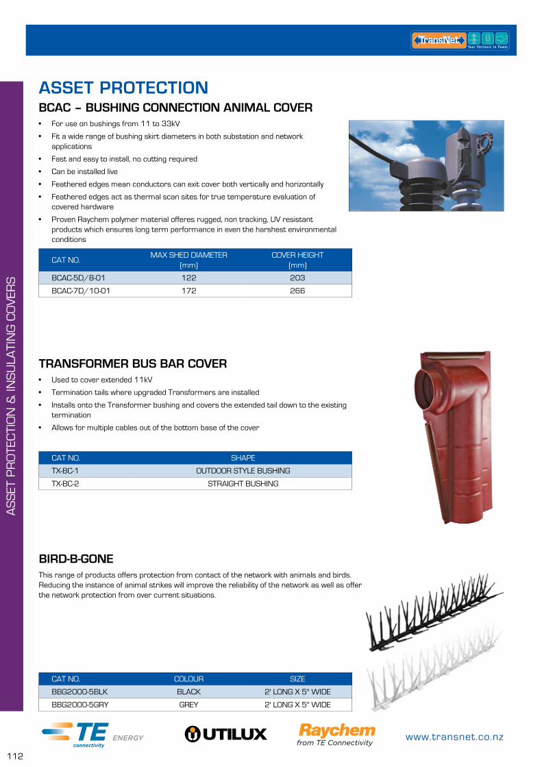
www.transnet.co.nz
112
AS
SET
PR
OTE
CTI
ON
& IN
SU
LATI
NG
CO
VER
S
BCAC – BUSHING CONNECTION ANIMAL COVER
TRANSFORMER BUS BAR COVER
• For use on bushings from 11 to 33kV
• Fit a wide range of bushing skirt diameters in both substation and network applications
• Fast and easy to install, no cutting required
• Can be installed live
• Feathered edges mean conductors can exit cover both vertically and horizontally
• Feathered edges act as thermal scan sites for true temperature evaluation of covered hardware
• Proven Raychem polymer material offeres rugged, non tracking, UV resistant products which ensures long term performance in even the harshest environmental conditions
• Used to cover extended 11kV
• Termination tails where upgraded Transformers are installed
• Installs onto the Transformer bushing and covers the extended tail down to the existing termination
• Allows for multiple cables out of the bottom base of the cover
CAT NO.MAX SHED DIAMETER
(mm)COVER HEIGHT
(mm)
BCAC-5D/8-01 122 203
BCAC-7D/10-01 172 266
CAT NO. SHAPE
TX-BC-1 OUTDOOR STYLE BUSHING
TX-BC-2 STRAIGHT BUSHING
ASSET PROTECTION
BIRD-B-GONEThis range of products offers protection from contact of the network with animals and birds. Reducing the instance of animal strikes will improve the reliability of the network as well as offer the network protection from over current situations.
CAT NO. COLOUR SIZE
BBG2000-5BLK BLACK 2' LONG X 5" WIDE
BBG2000-5GRY GREY 2' LONG X 5" WIDE
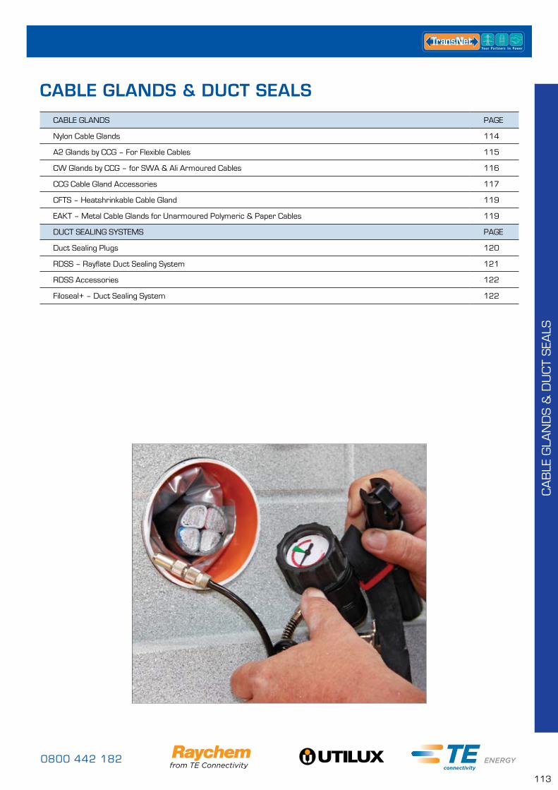
0800 442 182
113
CA
BLE
GLA
ND
S &
DU
CT
SEA
LS
CABLE GLANDS PAGE
Nylon Cable Glands 114
A2 Glands by CCG – For Flexible Cables 115
CW Glands by CCG – for SWA & Ali Armoured Cables 116
CCG Cable Gland Accessories 117
CFTS – Heatshrinkable Cable Gland 119
EAKT – Metal Cable Glands for Unarmoured Polymeric & Paper Cables 119
DUCT SEALING SYSTEMS PAGE
Duct Sealing Plugs 120
RDSS – Rayflate Duct Sealing System 121
RDSS Accessories 122
Filoseal+ – Duct Sealing System 122
CABLE GLANDS & DUCT SEALS
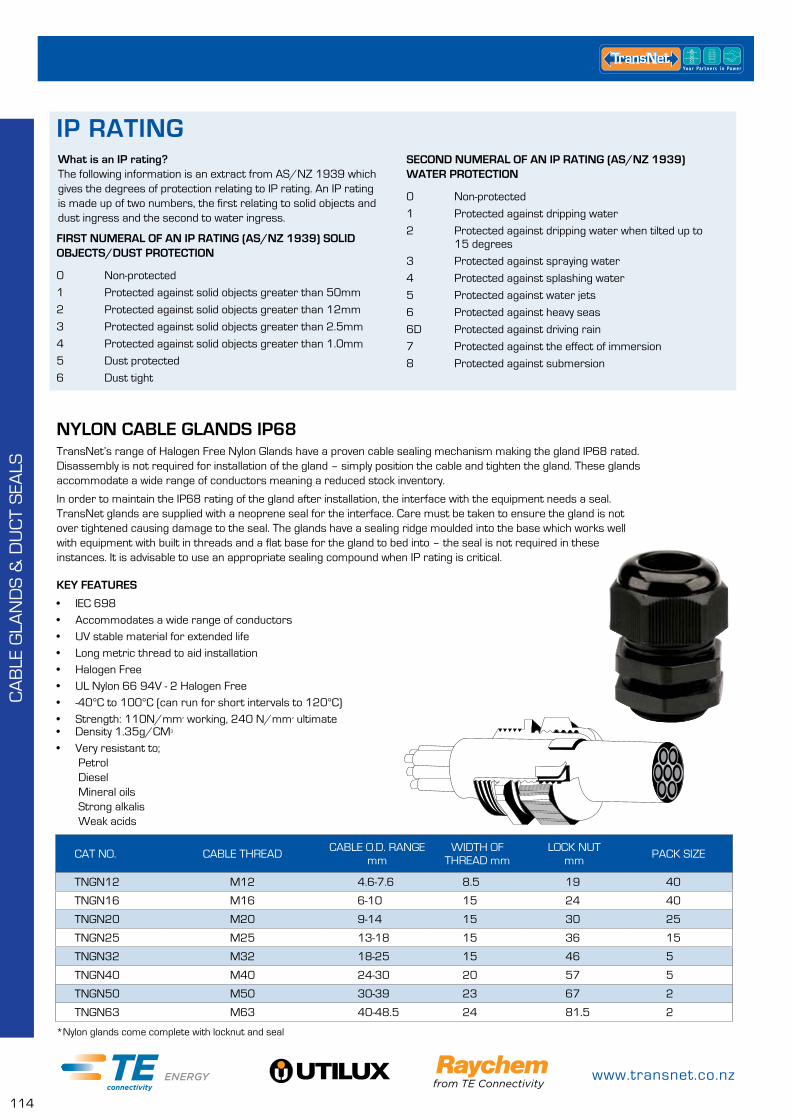
www.transnet.co.nz
114
CA
BLE
GLA
ND
S &
DU
CT
SEA
LS
NYLON CABLE GLANDS IP68
CAT NO. CABLE THREAD CABLE O.D. RANGEmm
WIDTH OF THREAD mm
LOCK NUTmm PACK SIZE
TNGN12 M12 4.6-7.6 8.5 19 40
TNGN16 M16 6-10 15 24 40
TNGN20 M20 9-14 15 30 25
TNGN25 M25 13-18 15 36 15
TNGN32 M32 18-25 15 46 5
TNGN40 M40 24-30 20 57 5
TNGN50 M50 30-39 23 67 2
TNGN63 M63 40-48.5 24 81.5 2
TransNet’s range of Halogen Free Nylon Glands have a proven cable sealing mechanism making the gland IP68 rated. Disassembly is not required for installation of the gland – simply position the cable and tighten the gland. These glands accommodate a wide range of conductors meaning a reduced stock inventory.
In order to maintain the IP68 rating of the gland after installation, the interface with the equipment needs a seal. TransNet glands are supplied with a neoprene seal for the interface. Care must be taken to ensure the gland is not over tightened causing damage to the seal. The glands have a sealing ridge moulded into the base which works well with equipment with built in threads and a flat base for the gland to bed into – the seal is not required in these instances. It is advisable to use an appropriate sealing compound when IP rating is critical.
KEY FEATURES
• IEC 698• Accommodates a wide range of conductors• UV stable material for extended life• Long metric thread to aid installation• Halogen Free• UL Nylon 66 94V - 2 Halogen Free• -40°C to 100°C (can run for short intervals to 120°C)• Strength: 110N/mm² working, 240 N/mm² ultimate• Density 1.35g/CM3
• Very resistant to; Petrol Diesel Mineral oils Strong alkalis Weak acids
*Nylon glands come complete with locknut and seal
FIRST NUMERAL OF AN IP RATING (AS/NZ 1939) SOLID OBJECTS/DUST PROTECTION
0 Non-protected
1 Protected against solid objects greater than 50mm
2 Protected against solid objects greater than 12mm
3 Protected against solid objects greater than 2.5mm
4 Protected against solid objects greater than 1.0mm
5 Dust protected
6 Dust tight
SECOND NUMERAL OF AN IP RATING (AS/NZ 1939) WATER PROTECTION
0 Non-protected
1 Protected against dripping water
2 Protected against dripping water when tilted up to 15 degrees
3 Protected against spraying water
4 Protected against splashing water
5 Protected against water jets
6 Protected against heavy seas
6D Protected against driving rain
7 Protected against the effect of immersion
8 Protected against submersion
What is an IP rating?The following information is an extract from AS/NZ 1939 which gives the degrees of protection relating to IP rating. An IP rating is made up of two numbers, the first relating to solid objects and dust ingress and the second to water ingress.
IP RATING
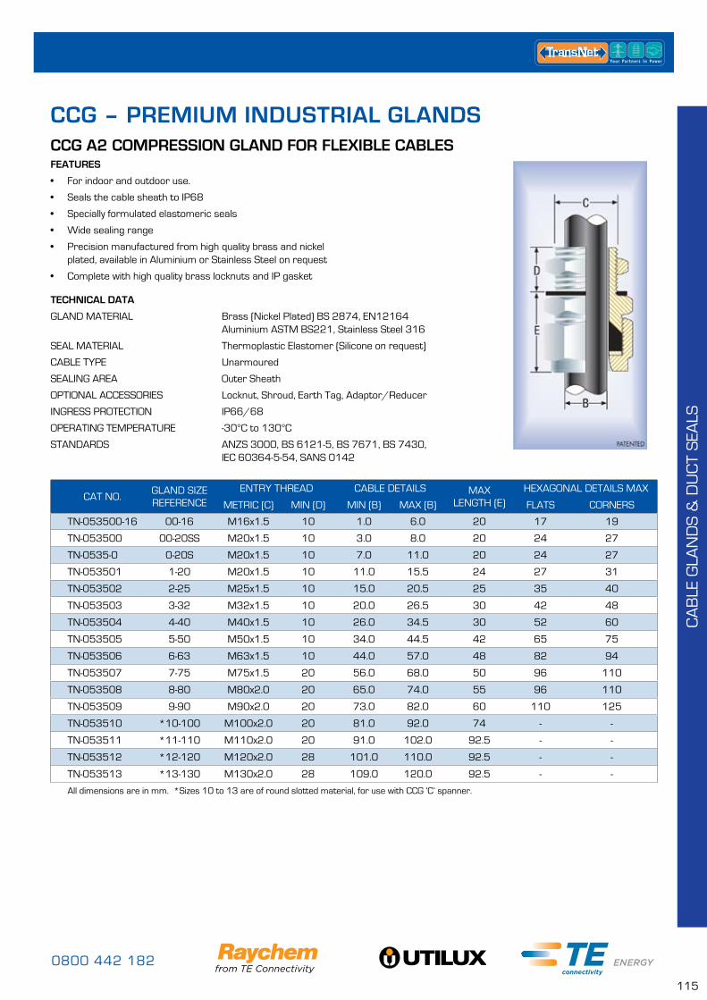
0800 442 182
115
CA
BLE
GLA
ND
S &
DU
CT
SEA
LS
CCG A2 COMPRESSION GLAND FOR FLEXIBLE CABLESFEATURES
• For indoor and outdoor use.
• Seals the cable sheath to IP68
• Specially formulated elastomeric seals
• Wide sealing range
• Precision manufactured from high quality brass and nickel plated, available in Aluminium or Stainless Steel on request
• Complete with high quality brass locknuts and IP gasket
CCG – PREMIUM INDUSTRIAL GLANDS
TECHNICAL DATA
GLAND MATERIAL Brass (Nickel Plated) BS 2874, EN12164 Aluminium ASTM BS221, Stainless Steel 316
SEAL MATERIAL Thermoplastic Elastomer (Silicone on request)
CABLE TYPE Unarmoured
SEALING AREA Outer Sheath
OPTIONAL ACCESSORIES Locknut, Shroud, Earth Tag, Adaptor/Reducer
INGRESS PROTECTION IP66/68
OPERATING TEMPERATURE -30°C to 130°C
STANDARDS ANZS 3000, BS 6121-5, BS 7671, BS 7430, IEC 60364-5-54, SANS 0142
CAT NO.GLAND SIZE REFERENCE
ENTRY THREAD CABLE DETAILS MAX LENGTH (E)
HEXAGONAL DETAILS MAX
METRIC (C) MIN (D) MIN (B) MAX (B) FLATS CORNERS
TN-053500-16 00-16 M16x1.5 10 1.0 6.0 20 17 19
TN-053500 00-20SS M20x1.5 10 3.0 8.0 20 24 27
TN-0535-0 0-20S M20x1.5 10 7.0 11.0 20 24 27
TN-053501 1-20 M20x1.5 10 11.0 15.5 24 27 31
TN-053502 2-25 M25x1.5 10 15.0 20.5 25 35 40
TN-053503 3-32 M32x1.5 10 20.0 26.5 30 42 48
TN-053504 4-40 M40x1.5 10 26.0 34.5 30 52 60
TN-053505 5-50 M50x1.5 10 34.0 44.5 42 65 75
TN-053506 6-63 M63x1.5 10 44.0 57.0 48 82 94
TN-053507 7-75 M75x1.5 20 56.0 68.0 50 96 110
TN-053508 8-80 M80x2.0 20 65.0 74.0 55 96 110
TN-053509 9-90 M90x2.0 20 73.0 82.0 60 110 125
TN-053510 *10-100 M100x2.0 20 81.0 92.0 74 - -
TN-053511 *11-110 M110x2.0 20 91.0 102.0 92.5 - -
TN-053512 *12-120 M120x2.0 28 101.0 110.0 92.5 - -
TN-053513 *13-130 M130x2.0 28 109.0 120.0 92.5 - -
All dimensions are in mm. *Sizes 10 to 13 are of round slotted material, for use with CCG ‘C’ spanner.
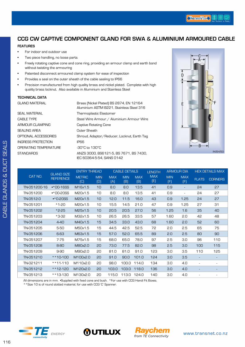
www.transnet.co.nz
116
CA
BLE
GLA
ND
S &
DU
CT
SEA
LS
CCG CW CAPTIVE COMPONENT GLAND FOR SWA & ALUMINIUM ARMOURED CABLEFEATURES
• For indoor and outdoor use
• Two piece handling, no loose parts
• Freely rotating captive cone and cone ring, providing an armour clamp and earth bond without twisting the armouring
• Patented disconnect armoured clamp system for ease of inspection
• Provides a seal on the outer sheath of the cable sealing to IP66
• Precision manufactured from high quality brass and nickel plated. Complete with high quality brass locknut. Also available in Aluminium and Stainless Steel
TECHNICAL DATA
GLAND MATERIAL Brass (Nickel Plated) BS 2874, EN 12164 Aluminium ASTM B221, Stainless Steel 316
SEAL MATERIAL Thermoplastic Elastomer
CABLE TYPE Steel Wire Armour / Aluminium Armour Wire
ARMOUR CLAMPING Captive Rotating Cone
SEALING AREA Outer Sheath
OPTIONAL ACCESSORIES Shroud, Adaptor/Reducer, Locknut, Earth Tag
INGRESS PROTECTION IP66
OPERATING TEMPERATURE -30°C to 130°C
STANDARDS ANZS 3000, BS6121-5, BS 7671, BS 7430, IEC 60364-5-54, SANS 0142
CAT NO.GLAND SIZE REFERENCE
ENTRY THREAD CABLE DETAILS LENGTH MAX (E)
ARMOUR DIA HEX DETAILS MAX
METRIC (C)
MIN (D)
MAX (A)
MIN (B)
MAX (B)
MIN (F)
MAX (F)
FLATS CORNERS
TN-051200-16 •*00-16SS M16x1.5 10 8.0 8.0 13.5 41 0.9 - 24 27
TN-051200 •*00-20SS M20x1.5 10 8.0 8.0 13.5 41 0.9 - 24 27
TN-0512-0 •*0-20SS M20x1.5 10 12.0 11.5 16.0 43 0.9 1.25 24 27
TN-051201 *1-20 M20x1.5 10 15.5 14.5 21.0 47 0.9 1.25 27 31
TN-051202 *2-25 M25x1.5 10 20.5 20.5 27.0 56 1.25 1.6 35 40
TN-051203 *3-32 M32x1.5 10 26.5 26.5 33.5 57 1.60 2.0 42 48
TN-051204 4-40 M40x1.5 15 34.5 33.0 43.0 68 1.60 2.0 52 60
TN-051205 5-50 M50x1.5 15 44.5 42.5 52.5 72 2.0 2.5 65 75
TN-051206 6-63 M63x1.5 15 57.0 52.0 65.5 89 2.0 2.5 80 90
TN-051207 7-75 M75x1.5 15 68.0 65.0 78.0 97 2.5 3.0 96 110
TN-051208 8-80 M80x2.0 20 73.0 77.5 82.0 98 2.5 3.0 100 115
TN-051209 9-90 M90x2.0 20 81.0 81.0 91.0 123 3.0 3.5 110 125
TN-051210 **10-100 M100x2.0 20 91.0 90.0 101.0 124 3.0 3.5 - -
TN-021211 **11-110 M110x2.0 20 98.0 100.0 114.0 134 3.0 4.0 - -
TN-051212 **12-120 M120x2.0 20 103.0 103.0 118.0 136 3.0 4.0 - -
TN-051213 **13-130 M130x2.0 20 115.0 113.0 124.0 140 3.0 4.0 - -
All dimensions are in mm. •Supplied with fixed cone and bush. *For use with CCG Handi Fit Boxes. **Size 10 is of round slotted material, for use with CCG ‘C’ Spanner.
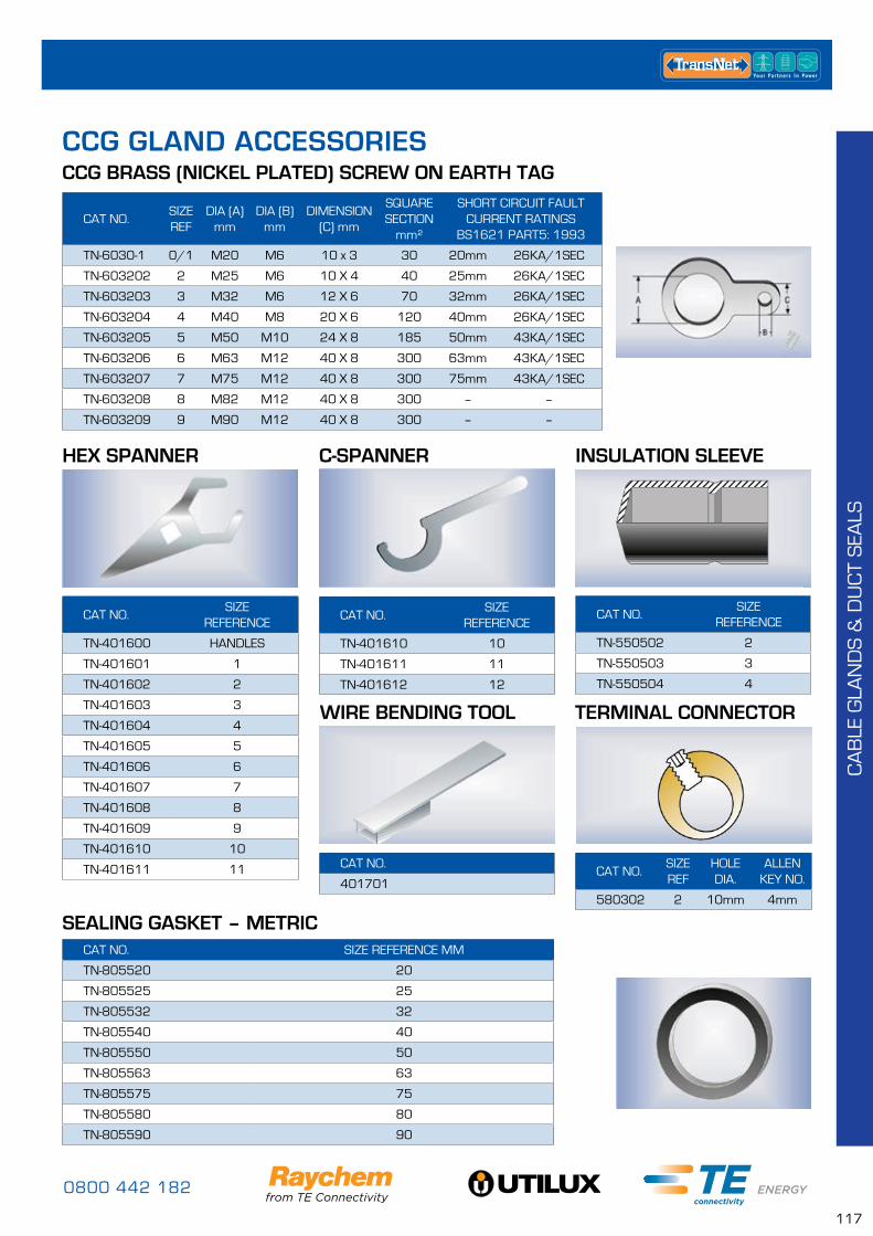
0800 442 182
117
CA
BLE
GLA
ND
S &
DU
CT
SEA
LS
CAT NO.SIZE REF
DIA (A)mm
DIA (B) mm
DIMENSION (C) mm
SQUARE SECTION
mm²
SHORT CIRCUIT FAULT CURRENT RATINGS
BS1621 PART5: 1993
TN-6030-1 0/1 M20 M6 10 x 3 30 20mm 26KA/1SEC
TN-603202 2 M25 M6 10 X 4 40 25mm 26KA/1SEC
TN-603203 3 M32 M6 12 X 6 70 32mm 26KA/1SEC
TN-603204 4 M40 M8 20 X 6 120 40mm 26KA/1SEC
TN-603205 5 M50 M10 24 X 8 185 50mm 43KA/1SEC
TN-603206 6 M63 M12 40 X 8 300 63mm 43KA/1SEC
TN-603207 7 M75 M12 40 X 8 300 75mm 43KA/1SEC
TN-603208 8 M82 M12 40 X 8 300 – –
TN-603209 9 M90 M12 40 X 8 300 – –
CAT NO.SIZE
REFERENCE
TN-401600 HANDLES
TN-401601 1
TN-401602 2
TN-401603 3
TN-401604 4
TN-401605 5
TN-401606 6
TN-401607 7
TN-401608 8
TN-401609 9
TN-401610 10
TN-401611 11
CAT NO.SIZE
REFERENCE
TN-401610 10
TN-401611 11
TN-401612 12
CAT NO.SIZE
REFERENCE
TN-550502 2
TN-550503 3
TN-550504 4
CAT NO.SIZE REF
HOLE DIA.
ALLEN KEY NO.
580302 2 10mm 4mm
CAT NO.
401701
CCG BRASS (NICKEL PLATED) SCREW ON EARTH TAG
HEX SPANNER C-SPANNER INSULATION SLEEVE
TERMINAL CONNECTORWIRE BENDING TOOL
CAT NO. SIZE REFERENCE MM
TN-805520 20
TN-805525 25
TN-805532 32
TN-805540 40
TN-805550 50
TN-805563 63
TN-805575 75
TN-805580 80
TN-805590 90
SEALING GASKET – METRIC
CCG GLAND ACCESSORIES
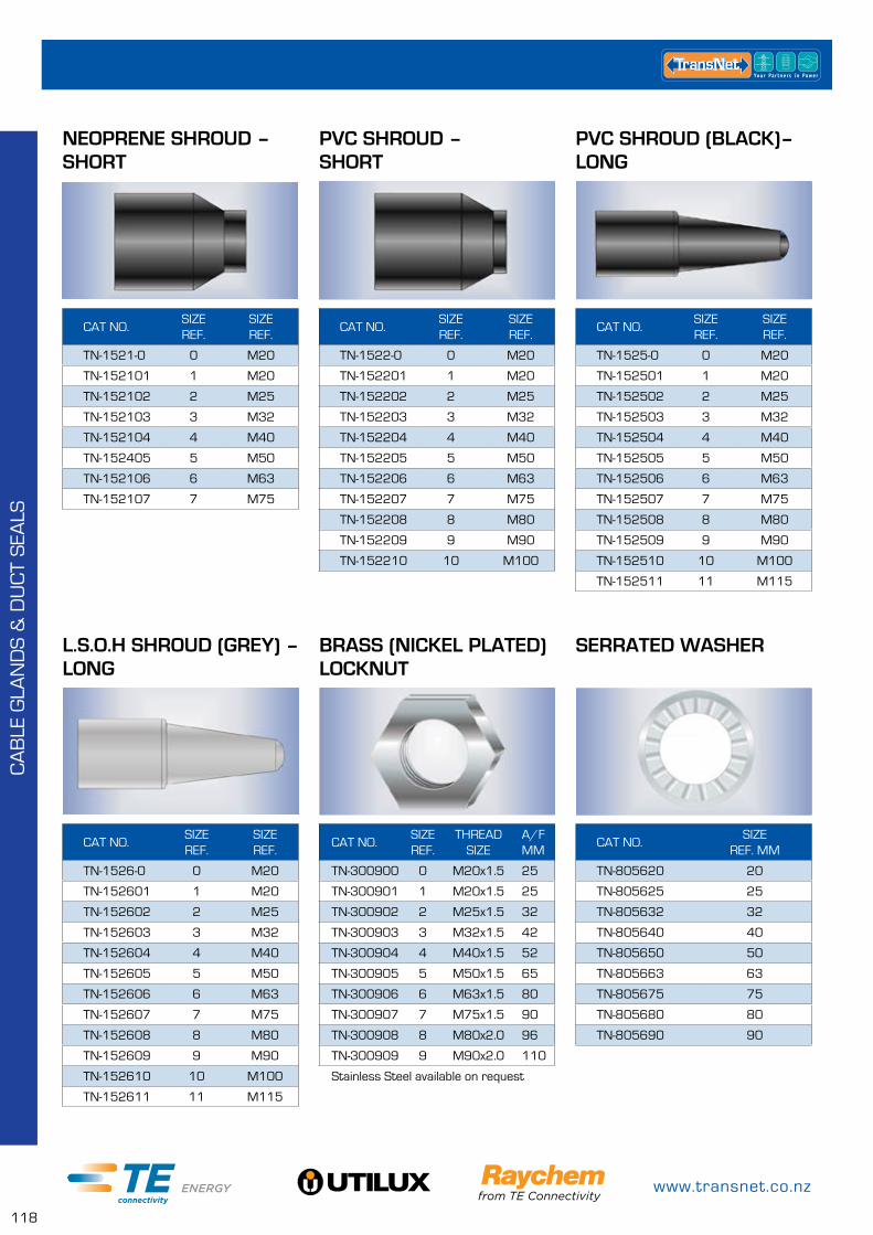
www.transnet.co.nz
118
CA
BLE
GLA
ND
S &
DU
CT
SEA
LS
CAT NO.SIZE REF.
SIZE REF.
TN-1521-0 0 M20
TN-152101 1 M20
TN-152102 2 M25
TN-152103 3 M32
TN-152104 4 M40
TN-152405 5 M50
TN-152106 6 M63
TN-152107 7 M75
CAT NO.SIZE REF.
SIZE REF.
TN-1526-0 0 M20
TN-152601 1 M20
TN-152602 2 M25
TN-152603 3 M32
TN-152604 4 M40
TN-152605 5 M50
TN-152606 6 M63
TN-152607 7 M75
TN-152608 8 M80
TN-152609 9 M90
TN-152610 10 M100
TN-152611 11 M115
CAT NO.SIZE REF.
SIZE REF.
TN-1522-0 0 M20
TN-152201 1 M20
TN-152202 2 M25
TN-152203 3 M32
TN-152204 4 M40
TN-152205 5 M50
TN-152206 6 M63
TN-152207 7 M75
TN-152208 8 M80
TN-152209 9 M90
TN-152210 10 M100
CAT NO.SIZE REF.
THREAD SIZE
A/F MM
TN-300900 0 M20x1.5 25
TN-300901 1 M20x1.5 25
TN-300902 2 M25x1.5 32
TN-300903 3 M32x1.5 42
TN-300904 4 M40x1.5 52
TN-300905 5 M50x1.5 65
TN-300906 6 M63x1.5 80
TN-300907 7 M75x1.5 90
TN-300908 8 M80x2.0 96
TN-300909 9 M90x2.0 110
Stainless Steel available on request
CAT NO.SIZE REF.
SIZE REF.
TN-1525-0 0 M20
TN-152501 1 M20
TN-152502 2 M25
TN-152503 3 M32
TN-152504 4 M40
TN-152505 5 M50
TN-152506 6 M63
TN-152507 7 M75
TN-152508 8 M80
TN-152509 9 M90
TN-152510 10 M100
TN-152511 11 M115
CAT NO.SIZE
REF. MM
TN-805620 20
TN-805625 25
TN-805632 32
TN-805640 40
TN-805650 50
TN-805663 63
TN-805675 75
TN-805680 80
TN-805690 90
NEOPRENE SHROUD – SHORT
L.S.O.H SHROUD (GREY) – LONG
PVC SHROUD – SHORT
BRASS (NICKEL PLATED) LOCKNUT
PVC SHROUD (BLACK)– LONG
SERRATED WASHER
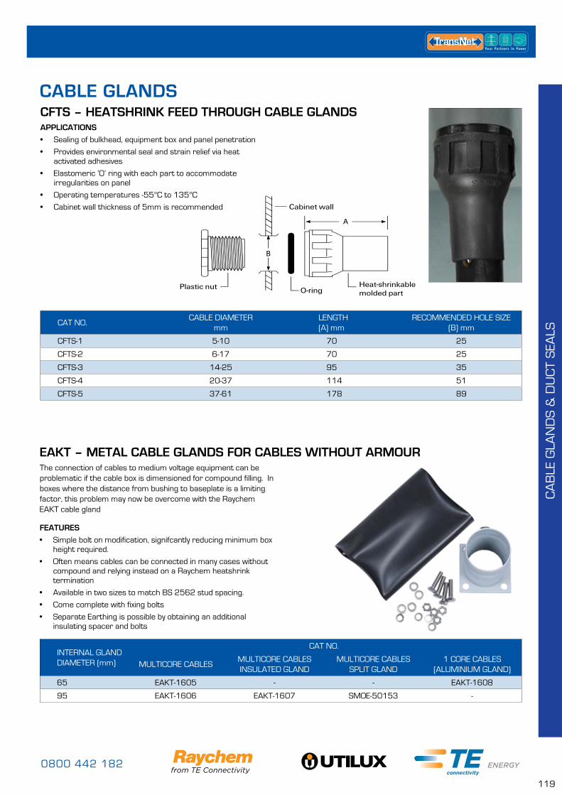
0800 442 182
119
CFTS – HEATSHRINK FEED THROUGH CABLE GLANDS
CAT NO.CABLE DIAMETER
mmLENGTH(A) mm
RECOMMENDED HOLE SIZE(B) mm
CFTS-1 5-10 70 25
CFTS-2 6-17 70 25
CFTS-3 14-25 95 35
CFTS-4 20-37 114 51
CFTS-5 37-61 178 89
APPLICATIONS
• Sealing of bulkhead, equipment box and panel penetration
• Provides environmental seal and strain relief via heat activated adhesives
• Elastomeric ‘O’ ring with each part to accommodate irregularities on panel
• Operating temperatures -55°C to 135°C
• Cabinet wall thickness of 5mm is recommended
CABLE GLANDS
EAKT – METAL CABLE GLANDS FOR CABLES WITHOUT ARMOURThe connection of cables to medium voltage equipment can be problematic if the cable box is dimensioned for compound filling. In boxes where the distance from bushing to baseplate is a limiting factor, this problem may now be overcome with the Raychem EAKT cable gland
FEATURES
• Simple bolt on modification, signifcantly reducing minimum box height required.
• Often means cables can be connected in many cases without compound and relying instead on a Raychem heatshrink termination
• Available in two sizes to match BS 2562 stud spacing.
• Come complete with fixing bolts
• Separate Earthing is possible by obtaining an additional insulating spacer and bolts
INTERNAL GLAND DIAMETER (mm)
CAT NO.
MULTICORE CABLESMULTICORE CABLES INSULATED GLAND
MULTICORE CABLES SPLIT GLAND
1 CORE CABLES (ALUMINIUM GLAND)
65 EAKT-1605 - - EAKT-1608
95 EAKT-1606 EAKT-1607 SMOE-50153 -
CA
BLE
GLA
ND
S &
DU
CT
SEA
LS
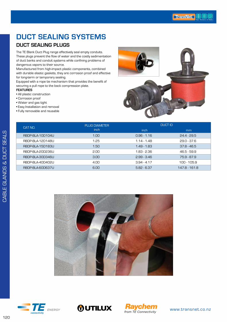
www.transnet.co.nz
120
DUCT SEALING SYSTEMSDUCT SEALING PLUGSThe TE Blank Duct Plug range effectively seal empty conduits. These plugs prevent the flow of water and the costly sedimentation of duct banks and conduit systems while confining problems of dangerous vapors to their source.Manufactured from high-impact plastic components, combined with durable elastic gaskets, they are corrosion proof and effective for long-term or temporary sealing.Equipped with a rope tie mechanism that provides the benefit of securing a pull rope to the back compression plate.FEATURES• All plastic construction• Corrosion proof• Water and gas tight• Easy Installation and removal• Fully removable and reusable
CAT NO.PLUG DIAMETER
inchDUCT ID
inch mm
RBDP-BLA-10D104U 1.00 0.96 - 1.16 24.4 - 29.5
RBDP-BLA-12D148U 1.25 1.14 - 1.48 29.0 - 37.6
RBDP-BLA-15D183U 1.50 1.49 - 1.83 37.8 - 46.5
RBDP-BLA-20D236U 2.00 1.83 - 2.36 46.5 - 59.9
RBDP-BLA-30D346U 3.00 2.99 - 3.46 75.9 - 87.9
RBDP-BLA-40D402U 4.00 3.94 - 4.17 100 - 105.9
RBDP-BLA-60D637U 6.00 5.82 - 6.37 147.8 - 161.8
CA
BLE
GLA
ND
S &
DU
CT
SEA
LS
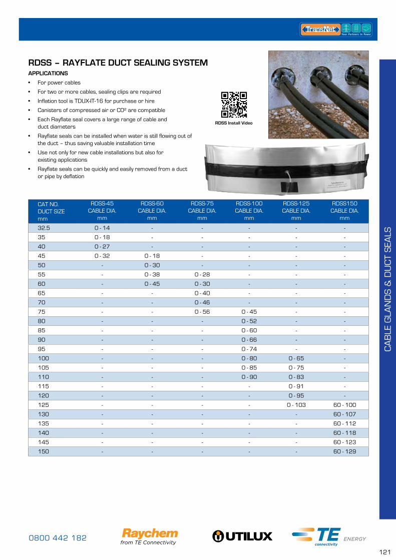
0800 442 182
121
RDSS – RAYFLATE DUCT SEALING SYSTEMAPPLICATIONS
• For power cables
• For two or more cables, sealing clips are required
• Inflation tool is TDUX-IT-16 for purchase or hire
• Canisters of compressed air or C0² are compatible
• Each Rayflate seal covers a large range of cable and duct diameters
• Rayflate seals can be installed when water is still flowing out of the duct – thus saving valuable installation time
• Use not only for new cable installations but also for existing applications
• Rayflate seals can be quickly and easily removed from a duct or pipe by deflation
CAT NO.DUCT SIZE mm
RDSS-45 CABLE DIA.
mm
RDSS-60CABLE DIA.
mm
RDSS-75CABLE DIA.
mm
RDSS-100CABLE DIA.
mm
RDSS-125CABLE DIA.
mm
RDSS150 CABLE DIA.
mm
32.5 0 - 14 - - - - -
35 0 - 18 - - - - -
40 0 - 27 - - - - -
45 0 - 32 0 - 18 - - - -
50 - 0 - 30 - - - -
55 - 0 - 38 0 - 28 - - -
60 - 0 - 45 0 - 30 - - -
65 - - 0 - 40 - - -
70 - - 0 - 46 - - -
75 - - 0 - 56 0 - 45 - -
80 - - - 0 - 52 - -
85 - - - 0 - 60 - -
90 - - - 0 - 66 - -
95 - - - 0 - 74 - -
100 - - - 0 - 80 0 - 65 -
105 - - - 0 - 85 0 - 75 -
110 - - - 0 - 90 0 - 83 -
115 - - - - 0 - 91 -
120 - - - - 0 - 95 -
125 - - - - 0 - 103 60 - 100
130 - - - - - 60 - 107
135 - - - - - 60 - 112
140 - - - - - 60 - 118
145 - - - - - 60 - 123
150 - - - - - 60 - 129
RDSS Install Video
CA
BLE
GLA
ND
S &
DU
CT
SEA
LS
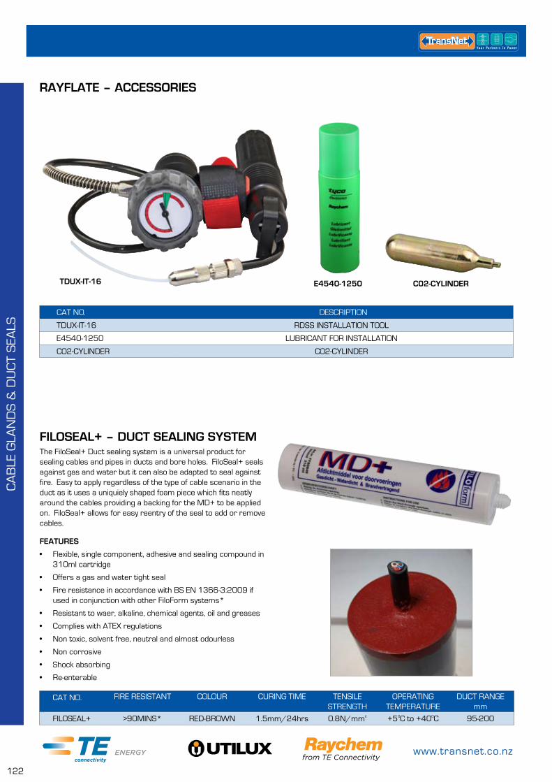
www.transnet.co.nz
122
CAT NO. DESCRIPTION
TDUX-IT-16 RDSS INSTALLATION TOOL
E4540-1250 LUBRICANT FOR INSTALLATION
CO2-CYLINDER CO2-CYLINDER
RAYFLATE – ACCESSORIES
CAT NO. FIRE RESISTANT COLOUR CURING TIME TENSILE STRENGTH
OPERATING TEMPERATURE
DUCT RANGEmm
FILOSEAL+ >90MINS* RED-BROWN 1.5mm/24hrs 0.8N/mm² +5OC to +40OC 95-200
FILOSEAL+ – DUCT SEALING SYSTEMThe FiloSeal+ Duct sealing system is a universal product for sealing cables and pipes in ducts and bore holes. FiloSeal+ seals against gas and water but it can also be adapted to seal against fire. Easy to apply regardless of the type of cable scenario in the duct as it uses a uniquiely shaped foam piece which fits neatly around the cables providing a backing for the MD+ to be applied on. FiloSeal+ allows for easy reentry of the seal to add or remove cables.
FEATURES
• Flexible, single component, adhesive and sealing compound in 310ml cartridge
• Offers a gas and water tight seal
• Fire resistance in accordance with BS EN 1366-3:2009 if used in conjunction with other FiloForm systems*
• Resistant to waer, alkaline, chemical agents, oil and greases
• Complies with ATEX regulations
• Non toxic, solvent free, neutral and almost odourless
• Non corrosive
• Shock absorbing
• Re-enterable
TDUX-IT-16 E4540-1250 C02-CYLINDER
CA
BLE
GLA
ND
S &
DU
CT
SEA
LS
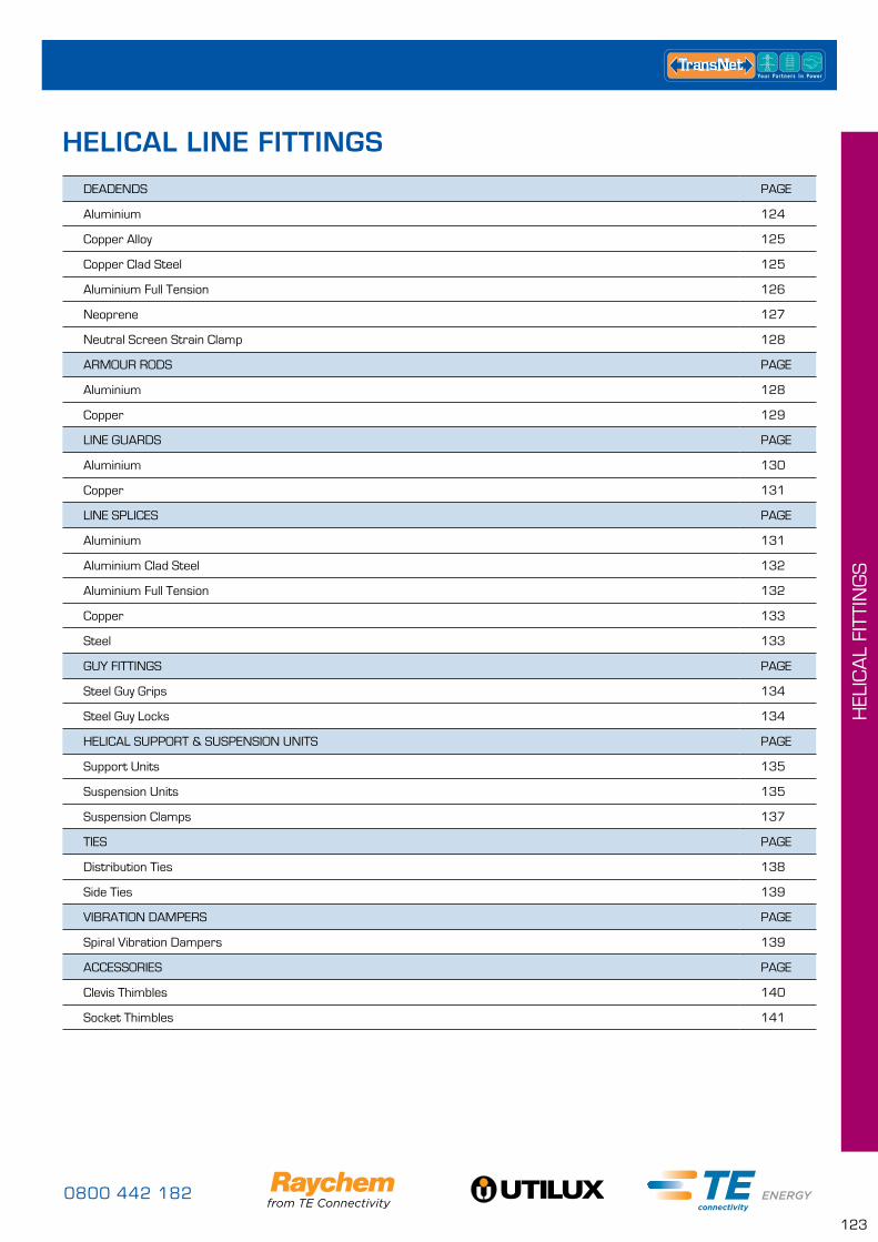
0800 442 182
123
HEL
ICA
L FI
TTIN
GS
DEADENDS PAGE
Aluminium 124
Copper Alloy 125
Copper Clad Steel 125
Aluminium Full Tension 126
Neoprene 127
Neutral Screen Strain Clamp 128
ARMOUR RODS PAGE
Aluminium 128
Copper 129
LINE GUARDS PAGE
Aluminium 130
Copper 131
LINE SPLICES PAGE
Aluminium 131
Aluminium Clad Steel 132
Aluminium Full Tension 132
Copper 133
Steel 133
GUY FITTINGS PAGE
Steel Guy Grips 134
Steel Guy Locks 134
HELICAL SUPPORT & SUSPENSION UNITS PAGE
Support Units 135
Suspension Units 135
Suspension Clamps 137
TIES PAGE
Distribution Ties 138
Side Ties 139
VIBRATION DAMPERS PAGE
Spiral Vibration Dampers 139
ACCESSORIES PAGE
Clevis Thimbles 140
Socket Thimbles 141
HELICAL LINE FITTINGS
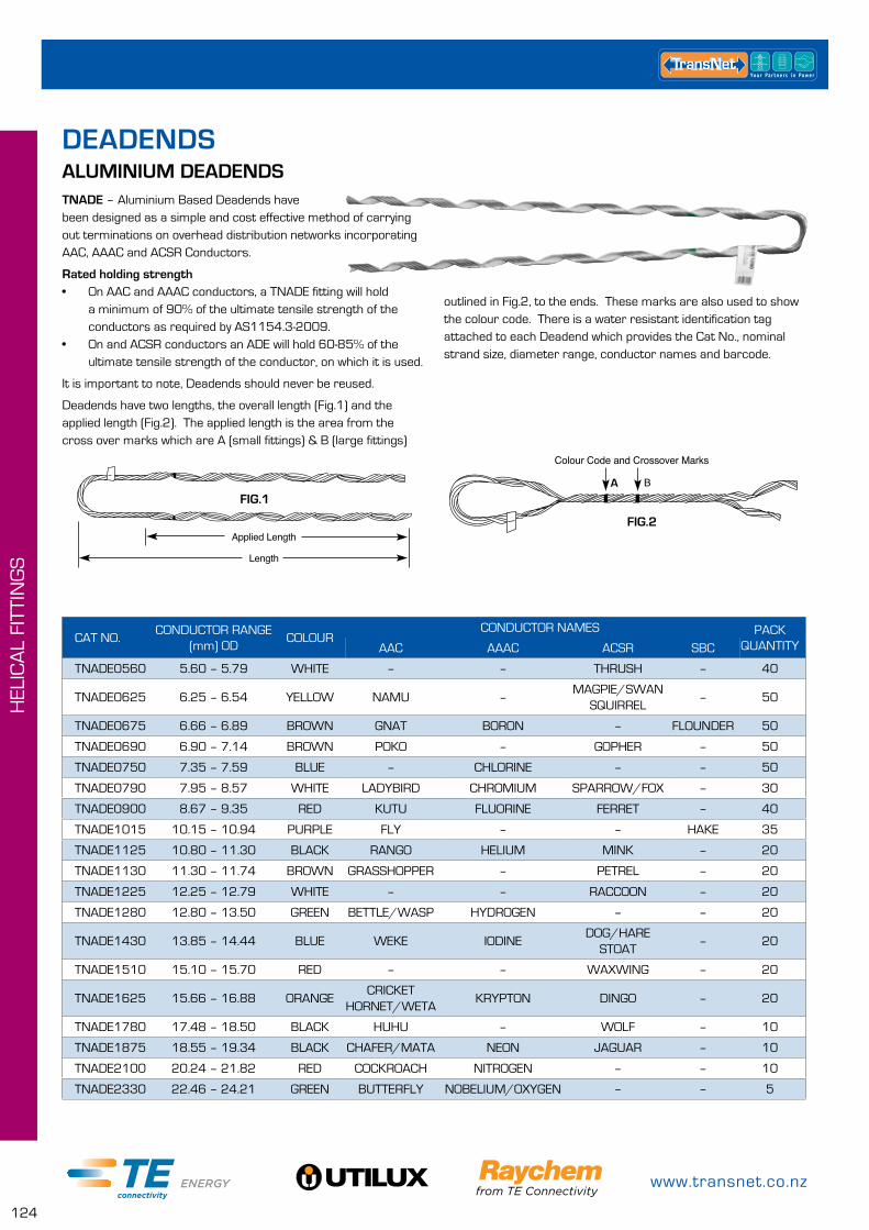
www.transnet.co.nz
124
HEL
ICA
L FI
TTIN
GS
TNADE – Aluminium Based Deadends have been designed as a simple and cost effective method of carrying out terminations on overhead distribution networks incorporating AAC, AAAC and ACSR Conductors.
Rated holding strength• On AAC and AAAC conductors, a TNADE fitting will hold
a minimum of 90% of the ultimate tensile strength of the conductors as required by AS1154.3-2009.
• On and ACSR conductors an ADE will hold 60-85% of the ultimate tensile strength of the conductor, on which it is used.
It is important to note, Deadends should never be reused.
Deadends have two lengths, the overall length (Fig.1) and the applied length (Fig.2). The applied length is the area from the cross over marks which are A (small fittings) & B (large fittings)
CAT NO.CONDUCTOR RANGE
(mm) ODCOLOUR
CONDUCTOR NAMES PACK QUANTITYAAC AAAC ACSR SBC
TNADE0560 5.60 – 5.79 WHITE – – THRUSH – 40
TNADE0625 6.25 – 6.54 YELLOW NAMU –MAGPIE/SWAN
SQUIRREL– 50
TNADE0675 6.66 – 6.89 BROWN GNAT BORON – FLOUNDER 50
TNADE0690 6.90 – 7.14 BROWN POKO – GOPHER – 50
TNADE0750 7.35 – 7.59 BLUE – CHLORINE – – 50
TNADE0790 7.95 – 8.57 WHITE LADYBIRD CHROMIUM SPARROW/FOX – 30
TNADE0900 8.67 – 9.35 RED KUTU FLUORINE FERRET – 40
TNADE1015 10.15 – 10.94 PURPLE FLY – – HAKE 35
TNADE1125 10.80 – 11.30 BLACK RANGO HELIUM MINK – 20
TNADE1130 11.30 – 11.74 BROWN GRASSHOPPER – PETREL – 20
TNADE1225 12.25 – 12.79 WHITE – – RACCOON – 20
TNADE1280 12.80 – 13.50 GREEN BETTLE/WASP HYDROGEN – – 20
TNADE1430 13.85 – 14.44 BLUE WEKE IODINEDOG/HARE
STOAT– 20
TNADE1510 15.10 – 15.70 RED – – WAXWING – 20
TNADE1625 15.66 – 16.88 ORANGECRICKET
HORNET/WETAKRYPTON DINGO – 20
TNADE1780 17.48 – 18.50 BLACK HUHU – WOLF – 10
TNADE1875 18.55 – 19.34 BLACK CHAFER/MATA NEON JAGUAR – 10
TNADE2100 20.24 – 21.82 RED COCKROACH NITROGEN – – 10
TNADE2330 22.46 – 24.21 GREEN BUTTERFLY NOBELIUM/OXYGEN – – 5
ALUMINIUM DEADENDS
Rod Diameter
Pitch Length
ConductorDiameter
Length
Applied Length
FIG.1 Open Loop
Colour Code and Crossover Marks
FIG.2
A
outlined in Fig.2, to the ends. These marks are also used to show the colour code. There is a water resistant identification tag attached to each Deadend which provides the Cat No., nominal strand size, diameter range, conductor names and barcode.
DEADENDS
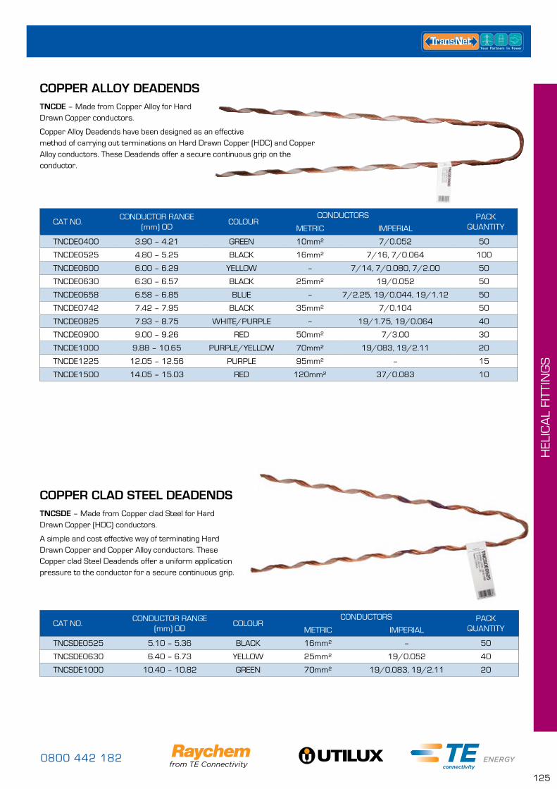
0800 442 182
125
HEL
ICA
L FI
TTIN
GS
TNCDE – Made from Copper Alloy for Hard Drawn Copper conductors.
Copper Alloy Deadends have been designed as an effective method of carrying out terminations on Hard Drawn Copper (HDC) and Copper Alloy conductors. These Deadends offer a secure continuous grip on the conductor.
CAT NO.CONDUCTOR RANGE
(mm) ODCOLOUR
CONDUCTORS PACK QUANTITYMETRIC IMPERIAL
TNCDE0400 3.90 – 4.21 GREEN 10mm² 7/0.052 50
TNCDE0525 4.80 – 5.25 BLACK 16mm² 7/16, 7/0.064 100
TNCDE0600 6.00 – 6.29 YELLOW – 7/14, 7/0.080, 7/2.00 50
TNCDE0630 6.30 – 6.57 BLACK 25mm² 19/0.052 50
TNCDE0658 6.58 – 6.85 BLUE – 7/2.25, 19/0.044, 19/1.12 50
TNCDE0742 7.42 – 7.95 BLACK 35mm² 7/0.104 50
TNCDE0825 7.93 – 8.75 WHITE/PURPLE – 19/1.75, 19/0.064 40
TNCDE0900 9.00 – 9.26 RED 50mm² 7/3.00 30
TNCDE1000 9.88 – 10.65 PURPLE/YELLOW 70mm² 19/083, 19/2.11 20
TNCDE1225 12.05 – 12.56 PURPLE 95mm² – 15
TNCDE1500 14.05 – 15.03 RED 120mm² 37/0.083 10
CAT NO.CONDUCTOR RANGE
(mm) ODCOLOUR
CONDUCTORS PACK QUANTITYMETRIC IMPERIAL
TNCSDE0525 5.10 – 5.36 BLACK 16mm² – 50
TNCSDE0630 6.40 – 6.73 YELLOW 25mm² 19/0.052 40
TNCSDE1000 10.40 – 10.82 GREEN 70mm² 19/0.083, 19/2.11 20
COPPER CLAD STEEL DEADENDS
COPPER ALLOY DEADENDS
TNCSDE – Made from Copper clad Steel for Hard Drawn Copper (HDC) conductors.
A simple and cost effective way of terminating Hard Drawn Copper and Copper Alloy conductors. These Copper clad Steel Deadends offer a uniform application pressure to the conductor for a secure continuous grip.
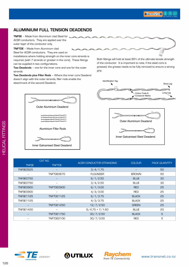
www.transnet.co.nz
126
HEL
ICA
L FI
TTIN
GS
TNFSE – Made from Aluminium clad Steel for ACSR conductors. They are applied over the outer layer of the conductor only.
TNFTDE – Made from Aluminium clad Steel for ACSR conductors. They are used on installations where holding strength on the inner core strands is required, (with 7 strands or greater in the core). These fittings can be supplied in two configurations. Two Deadends – one for the inner core and one for the outer strands Two Deadends plus Filler Rods – Where the inner core Deadend doesn’t align with the outer strands, filler rods enable the attachment of the second Deadend.
ALUMINIUM FULL TENSION DEADENDS
CAT NO.ACSR CONDUCTOR STRANDING COLOUR PACK QUANTITY
TNFSE TNFTDE
TNFSE0525 – 3/4/1.75 – 50
– TNFTDE0670 FLOUNDER BROWN 50
TNFSE0750 – 6/1/2.50 BLUE 30
TNFSE0750 – 3/4/2.50 BLUE 30
TNFSE0900 TNFTDE0900 6/1/3.00 RED 25
TNFSE0900 – 4/3/3.00 RED 25
TNFSE1125 TNFTDE1125 6/1/3.75 BLACK 25
TNFSE1125 – 4/3/3.75 BLACK 25
– TNFTDE1250 12/7/2.50 GREEN 25
TNFSE1430 – 6/4.75 + 7/1.60 BLUE 20
– TNFTDE1750 30/7/2.50 BLACK 5
– TNFTDE2100 30/7/3.00 RED 5
Long Leg
Colour Code &Crossover Marks
Identification TagShort Leg
Long Leg
Colour Code &Crossover Marks
Identification TagShort Leg
Long Leg
Colour Code &Crossover Marks
Identification TagShort Leg
Outer Aluminium Deadend
Inner Galvanised Steel Deadend
Outer Aluminium Deadend
Inner Galvanised Steel Deadend
Aluminium Filler Rods
Outer Aluminium Deadend
Inner Galvanised Steel Deadend
Outer Aluminium Deadend
Inner Galvanised Steel Deadend
Aluminium Filler Rods
Both fittings will hold at least 90% of the ultimate tensile strength of the conductor. It is important to note, if the steel core is greased, the grease needs to be fully removed to ensure a strong grip.
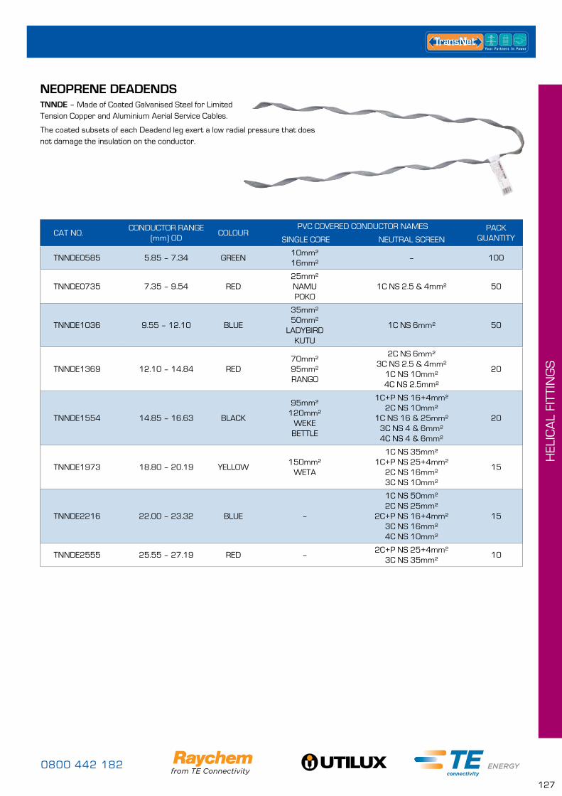
0800 442 182
127
HEL
ICA
L FI
TTIN
GS
CAT NO.CONDUCTOR RANGE
(mm) ODCOLOUR
PVC COVERED CONDUCTOR NAMES PACK QUANTITY SINGLE CORE NEUTRAL SCREEN
TNNDE0585 5.85 – 7.34 GREEN10mm² 16mm²
– 100
TNNDE0735 7.35 – 9.54 RED25mm² NAMU POKO
1C NS 2.5 & 4mm² 50
TNNDE1036 9.55 – 12.10 BLUE
35mm² 50mm²
LADYBIRD KUTU
1C NS 6mm² 50
TNNDE1369 12.10 – 14.84 RED70mm² 95mm² RANGO
2C NS 6mm² 3C NS 2.5 & 4mm²
1C NS 10mm² 4C NS 2.5mm²
20
TNNDE1554 14.85 – 16.63 BLACK
95mm² 120mm²
WEKE BETTLE
1C+P NS 16+4mm² 2C NS 10mm²
1C NS 16 & 25mm² 3C NS 4 & 6mm² 4C NS 4 & 6mm²
20
TNNDE1973 18.80 – 20.19 YELLOW150mm²
WETA
1C NS 35mm² 1C+P NS 25+4mm²
2C NS 16mm² 3C NS 10mm²
15
TNNDE2216 22.00 – 23.32 BLUE –
1C NS 50mm² 2C NS 25mm²
2C+P NS 16+4mm² 3C NS 16mm² 4C NS 10mm²
15
TNNDE2555 25.55 – 27.19 RED –2C+P NS 25+4mm²
3C NS 35mm²10
NEOPRENE DEADENDSTNNDE – Made of Coated Galvanised Steel for Limited Tension Copper and Aluminium Aerial Service Cables.
The coated subsets of each Deadend leg exert a low radial pressure that does not damage the insulation on the conductor.
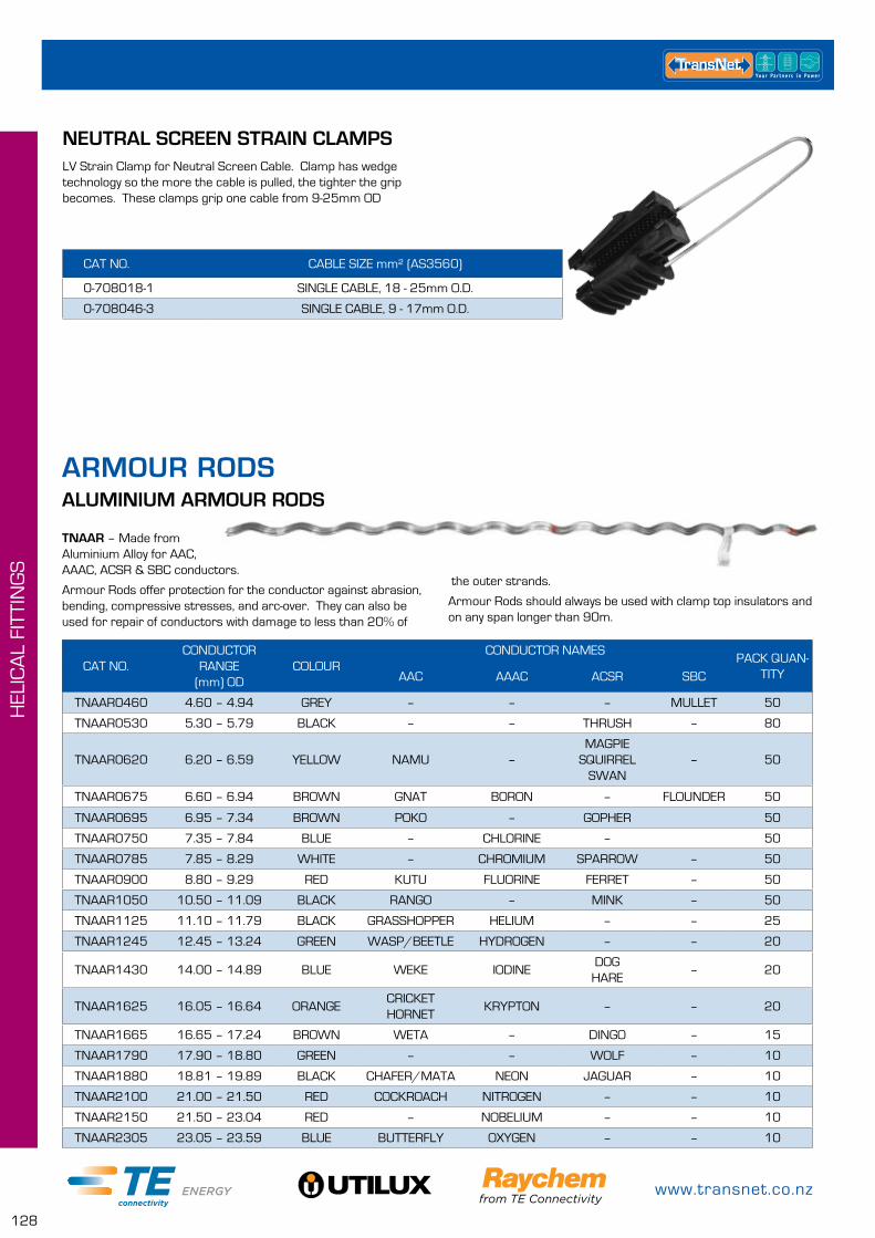
www.transnet.co.nz
128
HEL
ICA
L FI
TTIN
GS
TNAAR – Made from Aluminium Alloy for AAC, AAAC, ACSR & SBC conductors.
Armour Rods offer protection for the conductor against abrasion, bending, compressive stresses, and arc-over. They can also be used for repair of conductors with damage to less than 20% of
CAT NO.CONDUCTOR
RANGE (mm) OD
COLOURCONDUCTOR NAMES
PACK QUAN-TITYAAC AAAC ACSR SBC
TNAAR0460 4.60 – 4.94 GREY – – – MULLET 50
TNAAR0530 5.30 – 5.79 BLACK – – THRUSH – 80
TNAAR0620 6.20 – 6.59 YELLOW NAMU –MAGPIE
SQUIRREL SWAN
– 50
TNAAR0675 6.60 – 6.94 BROWN GNAT BORON – FLOUNDER 50
TNAAR0695 6.95 – 7.34 BROWN POKO – GOPHER 50
TNAAR0750 7.35 – 7.84 BLUE – CHLORINE – 50
TNAAR0785 7.85 – 8.29 WHITE – CHROMIUM SPARROW – 50
TNAAR0900 8.80 – 9.29 RED KUTU FLUORINE FERRET – 50
TNAAR1050 10.50 – 11.09 BLACK RANGO – MINK – 50
TNAAR1125 11.10 – 11.79 BLACK GRASSHOPPER HELIUM – – 25
TNAAR1245 12.45 – 13.24 GREEN WASP/BEETLE HYDROGEN – – 20
TNAAR1430 14.00 – 14.89 BLUE WEKE IODINEDOG
HARE– 20
TNAAR1625 16.05 – 16.64 ORANGECRICKET HORNET
KRYPTON – – 20
TNAAR1665 16.65 – 17.24 BROWN WETA – DINGO – 15
TNAAR1790 17.90 – 18.80 GREEN – – WOLF – 10
TNAAR1880 18.81 – 19.89 BLACK CHAFER/MATA NEON JAGUAR – 10
TNAAR2100 21.00 – 21.50 RED COCKROACH NITROGEN – – 10
TNAAR2150 21.50 – 23.04 RED – NOBELIUM – – 10
TNAAR2305 23.05 – 23.59 BLUE BUTTERFLY OXYGEN – – 10
ALUMINIUM ARMOUR RODS
the outer strands.
Armour Rods should always be used with clamp top insulators and on any span longer than 90m.
ARMOUR RODS
CAT NO. CABLE SIZE mm² (AS3560)
0-708018-1 SINGLE CABLE, 18 - 25mm O.D.
0-708046-3 SINGLE CABLE, 9 - 17mm O.D.
NEUTRAL SCREEN STRAIN CLAMPSLV Strain Clamp for Neutral Screen Cable. Clamp has wedge technology so the more the cable is pulled, the tighter the grip becomes. These clamps grip one cable from 9-25mm OD
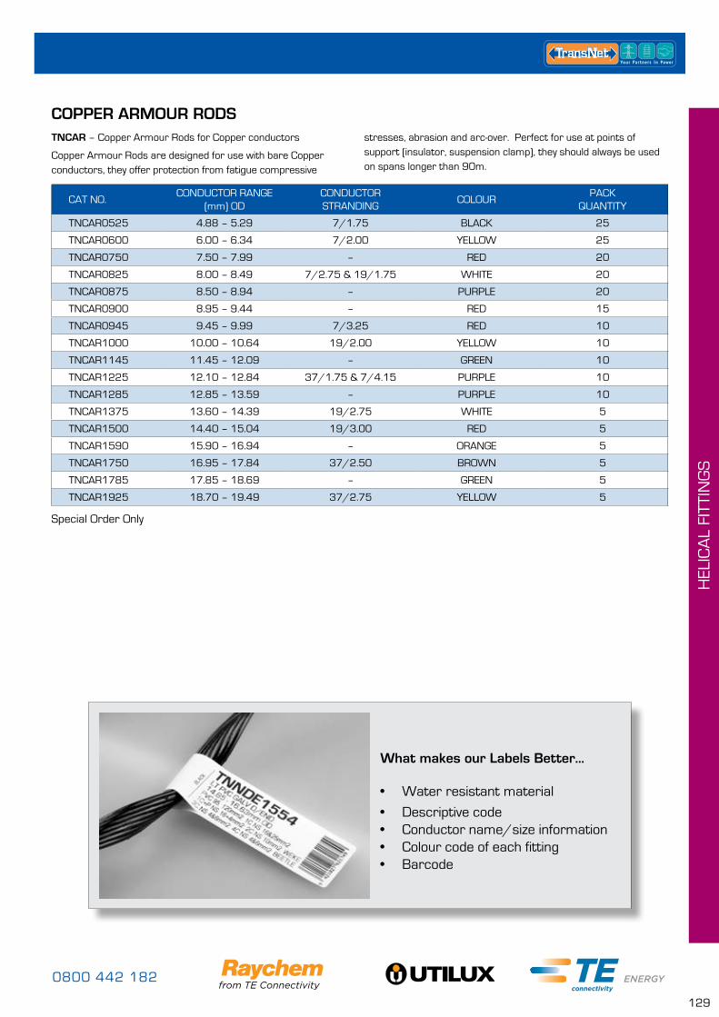
0800 442 182
129
HEL
ICA
L FI
TTIN
GS
CAT NO.CONDUCTOR RANGE
(mm) ODCONDUCTOR STRANDING
COLOURPACK
QUANTITY
TNCAR0525 4.88 – 5.29 7/1.75 BLACK 25
TNCAR0600 6.00 – 6.34 7/2.00 YELLOW 25
TNCAR0750 7.50 – 7.99 – RED 20
TNCAR0825 8.00 – 8.49 7/2.75 & 19/1.75 WHITE 20
TNCAR0875 8.50 – 8.94 – PURPLE 20
TNCAR0900 8.95 – 9.44 – RED 15
TNCAR0945 9.45 – 9.99 7/3.25 RED 10
TNCAR1000 10.00 – 10.64 19/2.00 YELLOW 10
TNCAR1145 11.45 – 12.09 – GREEN 10
TNCAR1225 12.10 – 12.84 37/1.75 & 7/4.15 PURPLE 10
TNCAR1285 12.85 – 13.59 – PURPLE 10
TNCAR1375 13.60 – 14.39 19/2.75 WHITE 5
TNCAR1500 14.40 – 15.04 19/3.00 RED 5
TNCAR1590 15.90 – 16.94 – ORANGE 5
TNCAR1750 16.95 – 17.84 37/2.50 BROWN 5
TNCAR1785 17.85 – 18.69 – GREEN 5
TNCAR1925 18.70 – 19.49 37/2.75 YELLOW 5
COPPER ARMOUR RODSTNCAR – Copper Armour Rods for Copper conductors
Copper Armour Rods are designed for use with bare Copper conductors, they offer protection from fatigue compressive
Special Order Only
What makes our Labels Better...
• Water resistant material
• Descriptive code• Conductor name/size information• Colour code of each fitting• Barcode
stresses, abrasion and arc-over. Perfect for use at points of support (insulator, suspension clamp), they should always be used on spans longer than 90m.
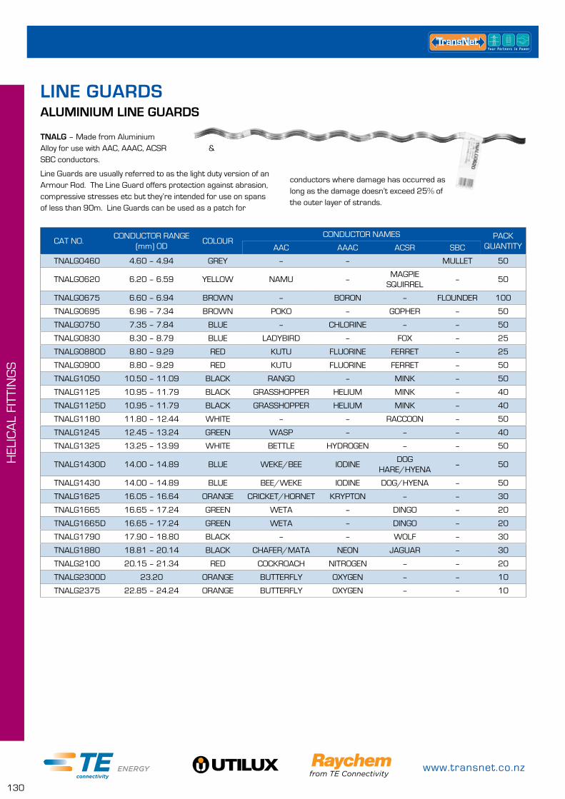
www.transnet.co.nz
130
HEL
ICA
L FI
TTIN
GS
TNALG – Made from Aluminium Alloy for use with AAC, AAAC, ACSR & SBC conductors.
Line Guards are usually referred to as the light duty version of an Armour Rod. The Line Guard offers protection against abrasion, compressive stresses etc but they’re intended for use on spans of less than 90m. Line Guards can be used as a patch for
CAT NO.CONDUCTOR RANGE
(mm) ODCOLOUR
CONDUCTOR NAMES PACK QUANTITYAAC AAAC ACSR SBC
TNALG0460 4.60 – 4.94 GREY – – MULLET 50
TNALG0620 6.20 – 6.59 YELLOW NAMU –MAGPIE
SQUIRREL– 50
TNALG0675 6.60 – 6.94 BROWN – BORON – FLOUNDER 100
TNALG0695 6.96 – 7.34 BROWN POKO – GOPHER – 50
TNALG0750 7.35 – 7.84 BLUE – CHLORINE – – 50
TNALG0830 8.30 – 8.79 BLUE LADYBIRD – FOX – 25
TNALG0880D 8.80 – 9.29 RED KUTU FLUORINE FERRET – 25
TNALG0900 8.80 – 9.29 RED KUTU FLUORINE FERRET – 50
TNALG1050 10.50 – 11.09 BLACK RANGO – MINK – 50
TNALG1125 10.95 – 11.79 BLACK GRASSHOPPER HELIUM MINK – 40
TNALG1125D 10.95 – 11.79 BLACK GRASSHOPPER HELIUM MINK – 40
TNALG1180 11.80 – 12.44 WHITE – – RACCOON – 50
TNALG1245 12.45 – 13.24 GREEN WASP – – – 40
TNALG1325 13.25 – 13.99 WHITE BETTLE HYDROGEN – – 50
TNALG1430D 14.00 – 14.89 BLUE WEKE/BEE IODINEDOG
HARE/HYENA– 50
TNALG1430 14.00 – 14.89 BLUE BEE/WEKE IODINE DOG/HYENA – 50
TNALG1625 16.05 – 16.64 ORANGE CRICKET/HORNET KRYPTON – – 30
TNALG1665 16.65 – 17.24 GREEN WETA – DINGO – 20
TNALG1665D 16.65 – 17.24 GREEN WETA – DINGO – 20
TNALG1790 17.90 – 18.80 BLACK – – WOLF – 30
TNALG1880 18.81 – 20.14 BLACK CHAFER/MATA NEON JAGUAR – 30
TNALG2100 20.15 – 21.34 RED COCKROACH NITROGEN – – 20
TNALG2300D 23.20 ORANGE BUTTERFLY OXYGEN – – 10
TNALG2375 22.85 – 24.24 ORANGE BUTTERFLY OXYGEN – – 10
ALUMINIUM LINE GUARDS
conductors where damage has occurred as long as the damage doesn’t exceed 25% of the outer layer of strands.
LINE GUARDS
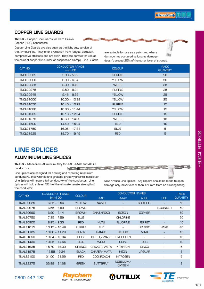
0800 442 182
131
HEL
ICA
L FI
TTIN
GS
CAT NO.CONDUCTOR RANGE
(mm) ODCOLOUR
PACK QUANTITY
TNCLG0525 5.00 – 5.29 PURPLE 50
TNCLG0600 6.00 – 6.34 YELLOW 50
TNCLG0825 8.00 – 8.49 WHITE 25
TNCLG0875 8.50 – 8.94 PURPLE 25
TNCLG0945 9.45 – 9.99 YELLOW 25
TNCLG1000 10.00 – 10.39 YELLOW 25
TNCLG1050 10.40 – 10.79 PURPLE 15
TNCLG1080 10.80 – 11.44 YELLOW 15
TNCLG1225 12.10 – 12.84 PURPLE 15
TNCLG1375 13.60 – 14.39 WHITE 15
TNCLG1500 14.40 – 15.04 RED 10
TNCLG1750 16.95 – 17.84 BLUE 5
TNCLG1925 18.70 – 19.49 RED 5
COPPER LINE GUARDSTNCLG – Copper Line Guards for Hard Drawn Copper (HDC) conductors
Copper Line Guards are also seen as the light duty version of the Armour Rod. They offer protection from fatigue, abrasion, compressive stresses and arc-over. They are perfect for use at the point of support (insulator or suspension clamp). Line Guards
ALUMINIUM LINE SPLICES
CAT NO.CONDUCTOR RANGE
(mm) ODCOLOUR
CONDUCTOR NAMES PACK QUANTITYAAC AAAC ACSR SBC
TNALS0625 6.25 – 6.54 YELLOW NAMU – SQUIRREL – 50
TNALS0675 6.55 – 6.89 BROWN – – – FLOUNDER 50
TNALS0690 6.90 – 7.14 BROWN GNAT/POKO BORON GOPHER – 50
TNALS0750 7.35 – 7.59 BLUE – CHLORINE – – 50
TNALS0900 8.95 – 9.35 RED KUTU FLUORINE FERRET – 40
TNALS1015 10.15 – 10.49 PURPLE FLY – RABBIT HAKE 40
TNALS1125 10.80 – 11.29 BLACK RANGO HELIUM MINK – 15
TNALS1350 13.24 – 13.84 GREY BEETLE/WASP HYDROGEN – – 10
TNALS1430 13.85 – 14.44 BLUE WETA IODINE DOG – 10
TNALS1625 15.70 – 16.39 ORANGE CRICKET/WETA KRYPTON DINGO – 5
TNALS1875 18.55–19.34 BLACK CHAFER/MATA NEON JAGUAR – 5
TNALS2100 21.00 – 21.59 RED COCKROACH NITROGEN – – 5
TNALS2375 22.89 – 24.68 GREEN BUTTERFLYNOBELIUM/
OXYGEN– – 3
TNALS – Made from Aluminium Alloy for AAC, AAAC and ACSR conductors.
Line Splices are designed for splicing and repairing Aluminium conductors. If scratched and greased properly prior to installation Line Splices will restore full conductivity of the conductor. Line Splices will hold at least 90% of the ultimate tensile strength of the conductor.
Never reuse Line Splices. Any repairs should be made to span damage only, never closer than 150mm from an existing fitting.
are suitable for use as a patch rod where damage has occurred as long as damage doesn’t exceed 25% of the outer layer of strands.
LINE SPLICES
www.transnet.co.nz
132
HEL
ICA
L FI
TTIN
GS
TNLLS – Aluminium clad Steel Line Splices for SC/AC conductors (Left Hand Lay is standard)
ALUMINIUM CLAD STEEL LINE SPLICES
CAT NO.CONDUCTOR RANGE
(mm) ODCONDUCTOR STRAND-
INGCOLOUR
PACK QUANTITY
TNLLS0525L 5.25 – 5.60 – PURPLE 50
TNLLS0593L 5.60 – 5.94 3/2.75 YELLOW 50
TNLLS0700L 6.75 – 7.27 3/3.25 BLUE 50
TNLLS0825L 8.00 – 8.29 3/3.75 & 7/2.75 WHITE 20
TNLLS0975L 9.70 – 10.04 7/3.25 ORANGE 20
TNLLS1125L 10.84 – 11.69 7/3.75 GREEN 20
TNLLS1375L 13.25 – 14.29 19/2.75 WHITE 5
TNLLS1625L 15.75 – 16.51 19/3.25 ORANGE 5
CAT NO.CONDUCTOR RANGE
(mm) ODCOLOUR
CONDUCTOR NAMES PACK QUANTITYACSR SBC
TNFTS0565 4.9 WHITE THRUSH
TNFTS0635 6.33 YELLOW SQUIRREL – 30
TNFTS0670 6.70 BROWN – FLOUNDER 30
TNFTS0709 7.08 BROWN GOPHER – 20
TNFTS0900 9.00 RED FERRET – 20
TNFTS1080 10.98 BLACK MINK – 15
TNFTS1420 14.15 BLUE DOG – 10
TNFTS1547 15.47 BROWN WAXWING – 10
TNFTS1075 16.75 BROWN DINGO – 10
TNFTS1810 18.13 WHITE WOLF – 10
TNFTS1930 19.30 BLACK JAGUAR – 10
TNFTS2100 21.00 RED LEMON – 10
ALUMINIUM FULL TENSION LINE SPLICESTNFTS – Full Tension Multi Piece Line Splice. Galvanised Steel & Aluminium Alloy for 6/1 or 30/7 ACSR conductors
Full Tension Line Splices are designed for splicing ACSR conductor. The multi piece design holds both the inner steel core, and the outer layers. In some cases filler rods may be needed to bridge the gap between the inner core and the outer strands. The conductor will be returned to full conductivity when spliced with TNFTS.
On ACSR conductors, full tension line splices hold at least 90% of the ultimate tensile strength of the conductor.
Inner spliceAluminium Conductor
Outer splice
Butt jointSteel core
Conductors should be scratch brushed and greased properly prior to installation to ensure a long term joint, and never placed closer than 360mm from other fit-tings. Do not reuse these fittings.
0800 442 182
133
HEL
ICA
L FI
TTIN
GS
CAT NO. CONDUCTOR RANGE (mm) OD CONDUCTOR STRANDING COLOUR PACK QTY
TNCLS0400 3.90 – 4.21 7/1.35 PURPLE 50
TNCLS0525 4.80 – 5.25 7/1.75 PURPLE 50
TNCLS0600 6.00 – 6.27 7/2.00 YELLOW 50
TNCLS0660 6.54 – 6.87 – BLACK 50
TNCLS0740 7.40 – 7.69 – GREEN 30
TNCLS0770 7.70 – 8.09 – ORANGE 20
TNCLS0825D 8.10 – 8.75 7/2.75 & 19/1.75 WHITE 20
TNCLS0900 8.76 – 9.23 – RED 15
TNCLS0965 9.24 – 9.99 7/3.25 PURPLE 10
TNCLS1000 10.00 – 10.54 19/2.00 & 7/3.50 YELLOW 10
TNCLS1068 10.55 – 11.08 – YELLOW 10
TNCLS1125 11.25 – 11.69 19/2.75 YELLOW 10
TNCLS1225 12.05 – 12.54 37/1.75 & 7/4.15 PURPLE 10
TNCLS1255 12.55 – 13.09 – YELLOW 10
TNCLS1375 13.65 – 14.09 19/2.75 WHITE 5
TNCLS1500 14.50 – 15.04 19/3.00 RED 5
TNCLS1750 16.39 – 17.66 37/2.50 BLUE 5
TNCLS1809 18.09 – 18.67 – ORANGE 5
TNCLS1885 18.68 – 19.64 37/2.75 BLACK 5
TNCLS1965 19.65 – 20.48 – GREEN 2
TNCLS2100 20.49 – 21.54 – RED 2
TNCLS2300 23.00 – 23.94 – GREEN 2
TNCLS2950 28.43 – 30.65 – BLACK 2
COPPER LINE SPLICESTNCLS – Copper Line Splices for Hard Drawn Copper (HDC) conductors
What makes our Helical Fittings Better...
• Water resistant label
• Informative label• Familiar colour code (as per AS1154)• Descriptive, familiar product code• Comprehensive range of products
CAT NO.CONDUCTOR RANGE
(mm) ODCOLOUR STRANDING
PACK QUANTITY
TNSLS0245 2.45 – 2.64 BLUE – 50
TNSLS0431 4.15 – 4.49 YELLOW 3/2.00 50
TNSLS0480 4.5 – 4.99 BLACK 7/1.60 50
TNSLS0593 5.50 – 5.94 WHITE 3/2.75 50
TNSLS0600 5.95 – 6.19 YELLOW 7/2.00 50
TNSLS0675 6.51 – 7.01 BROWN – 50
TNSLS0735 7.35 – 7.64 BLUE – 30
TNSLS0825 7.92 – 8.29 WHITE 7/2.75 30
TNSLS0975 9.70 – 10.04 YELLOW – 20
TNSLS1125 11.15 – 11.49 BLACK 7/3.75 20
TNSLS1200 11.85 – 12.19 BLACK 7/4.00 10
TNSLS1375 13.05 – 13.99 WHITE 19/2.75 10
TNSLS1625 16.00 – 16.44 ORANGE 19/3.25 5
STEEL LINE SPLICESTNSLS – Galvanised Steel for SC/GZ conductors.
For jointing and restorative repair of Galvanised Steel conductors. The TNSLS range will hold a minimum of 90% of the ultimate tensile strength of the conductor, when used on Galvanised Steel conductors.
www.transnet.co.nz
134
HEL
ICA
L FI
TTIN
GS
STEEL GUY GRIPSTNSGG – Galvanised Steel for SC/GZ conductors.
Used for terminating guy wires, earth wires and stay conductors. Guy Grips will hold 100% of the UTS of the wire they are applied to.
CAT NO.CONDUCTOR RANGE
(mm) ODCOLOUR CONDUCTORS
PACK QUANTITY
TNSGG0480 4.63 – 4.99 BLACK 7/1.60 SC/GZ 70
TNSGG0600 5.95 – 6.19 YELLOW 7/14, 7/2.00 SC/GZ, 6mm STEEL ROPE 50
TNSGG0620 6.20 – 6.49 YELLOW – 50
TNSGG0750 7.35 – 7.64 BLUE 7/2.50 SC/GZ 20
TNSGG0765 7.65 – 7.99 WHITE 7/12, 7/2.64 SC/GZ 40
TNSGG0825 7.90 – 8.29 WHITE 7/12, 19/16, 7/2.75 SC/GZ 20
TNSGG0895 8.95 – 9.29 RED 7/3.00 30
TNSGG0930 9.30 – 9.69 BLUE – 20
TNSGG0975 9.70 – 10.20 YELLOW/ORANGE 7/10, 19/2, 7/3.25 SC/GZ 20
TNSGG1200 11.85 – 12.19 BLACK 7/8, 7/4.00 SC/GZ 20
TNSGG1375 13.06 – 13.97 WHITE 19/2.75 SC/GZ 5
TNSGG1625 16.00 – 16.40 ORANGE 19/10, 19/3.25 SC/GZ 10
CAT NO.CONDUCTOR RANGE
(mm) ODCOLOUR CONDUCTORS
PACK QUANTITY
TNSGL0480 4.63 – 4.99 BLACK 7/16, 7/1.60 SC/GZ 50
TNSGL0735 7.35 – 7.64 BLUE – 30
TNSGL0765 7.65 – 7.99 WHITE 7/12, 7/2.64 SC/GZ 40
TNSGL0825 7.90 – 8.29 WHITE 7/12, 19/16, 7/2.75 SC/GZ 50
TNSGL0895 8.95 – 9.29 RED 7/3.00 45
TNSGL0930 9.30 – 9.69 BLUE 7/3.15 30
TNSGL0975 9.70 – 10.20 YELLOW/ORANGE 7/10, 19/2.00, 7/3.25 SC/GZ 30
TNSGL1200 11.84 – 12.17 BLACK 7/4.00 SC/GZ 25
TNSGL1625 15.98 – 16.41 ORANGE 19/10, 19/3.25 SC/GZ 10
STEEL GUY LOCKSTNSGL – Galvanised Steel for SC/GZ conductors.
Guy Locks are used as a neat, high strength and fast way to secure pole anchoring guys. Guy Locks will hold 100% of the UTS of the wire they are applied to.
GUY FITTINGS
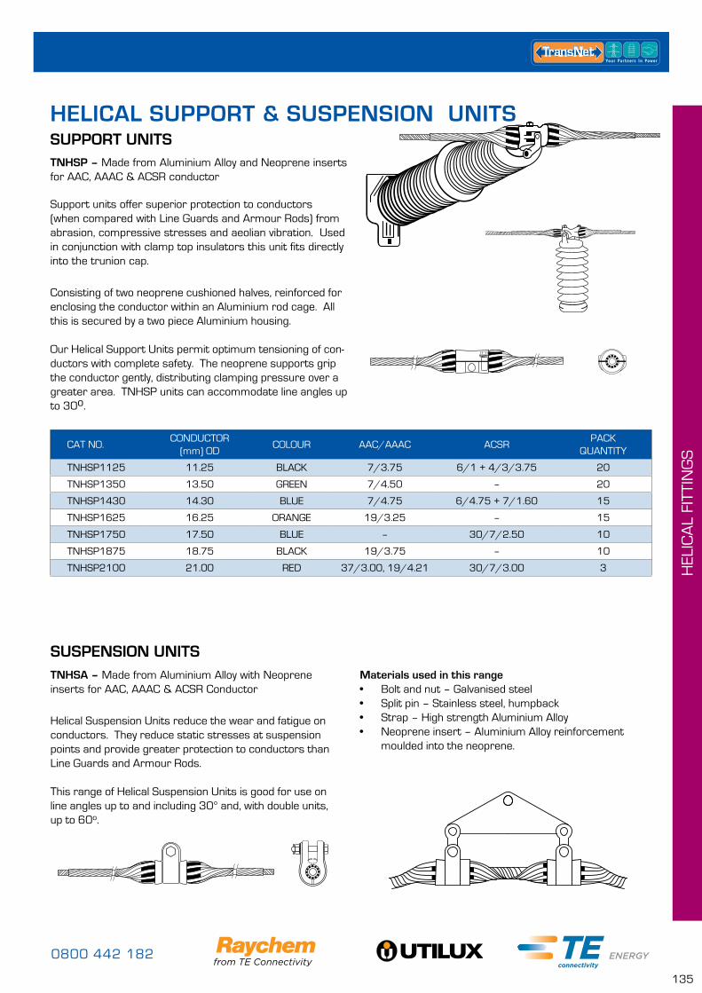
0800 442 182
135
HEL
ICA
L FI
TTIN
GS
SUSPENSION UNITSTNHSA – Made from Aluminium Alloy with Neoprene inserts for AAC, AAAC & ACSR Conductor
Helical Suspension Units reduce the wear and fatigue on conductors. They reduce static stresses at suspension points and provide greater protection to conductors than Line Guards and Armour Rods.
This range of Helical Suspension Units is good for use on line angles up to and including 30° and, with double units, up to 60o.
Materials used in this range• Bolt and nut – Galvanised steel• Split pin – Stainless steel, humpback• Strap – High strength Aluminium Alloy• Neoprene insert – Aluminium Alloy reinforcement
moulded into the neoprene.
SUPPORT UNITSTNHSP – Made from Aluminium Alloy and Neoprene inserts for AAC, AAAC & ACSR conductor
Support units offer superior protection to conductors (when compared with Line Guards and Armour Rods) from abrasion, compressive stresses and aeolian vibration. Used in conjunction with clamp top insulators this unit fits directly into the trunion cap.
Consisting of two neoprene cushioned halves, reinforced for enclosing the conductor within an Aluminium rod cage. All this is secured by a two piece Aluminium housing.
Our Helical Support Units permit optimum tensioning of con-ductors with complete safety. The neoprene supports grip the conductor gently, distributing clamping pressure over a greater area. TNHSP units can accommodate line angles up to 30o.
CAT NO.CONDUCTOR
(mm) ODCOLOUR AAC/AAAC ACSR
PACK QUANTITY
TNHSP1125 11.25 BLACK 7/3.75 6/1 + 4/3/3.75 20
TNHSP1350 13.50 GREEN 7/4.50 – 20
TNHSP1430 14.30 BLUE 7/4.75 6/4.75 + 7/1.60 15
TNHSP1625 16.25 ORANGE 19/3.25 – 15
TNHSP1750 17.50 BLUE – 30/7/2.50 10
TNHSP1875 18.75 BLACK 19/3.75 – 10
TNHSP2100 21.00 RED 37/3.00, 19/4.21 30/7/3.00 3
HELICAL SUPPORT & SUSPENSION UNITS
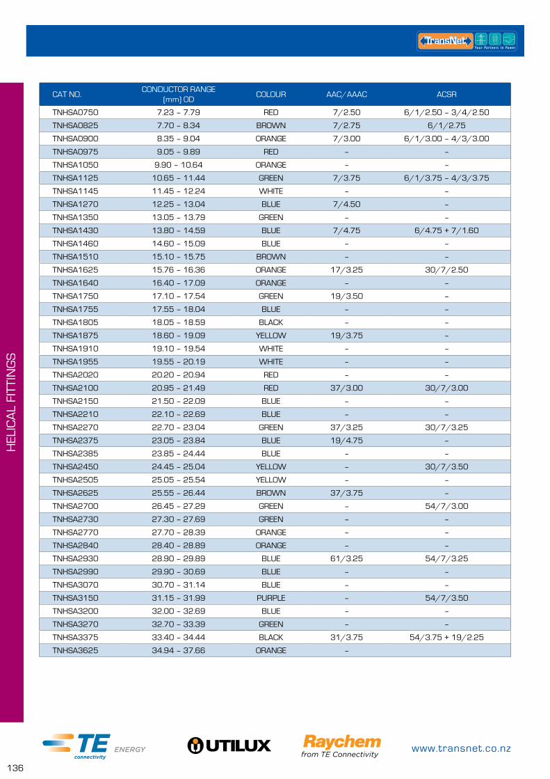
www.transnet.co.nz
136
HEL
ICA
L FI
TTIN
GS
CAT NO.CONDUCTOR RANGE
(mm) ODCOLOUR AAC/AAAC ACSR
TNHSA0750 7.23 – 7.79 RED 7/2.50 6/1/2.50 – 3/4/2.50
TNHSA0825 7.70 – 8.34 BROWN 7/2.75 6/1/2.75
TNHSA0900 8.35 – 9.04 ORANGE 7/3.00 6/1/3.00 – 4/3/3.00
TNHSA0975 9.05 – 9.89 RED – –
TNHSA1050 9.90 – 10.64 ORANGE – –
TNHSA1125 10.65 – 11.44 GREEN 7/3.75 6/1/3.75 – 4/3/3.75
TNHSA1145 11.45 – 12.24 WHITE – –
TNHSA1270 12.25 – 13.04 BLUE 7/4.50 –
TNHSA1350 13.05 – 13.79 GREEN – –
TNHSA1430 13.80 – 14.59 BLUE 7/4.75 6/4.75 + 7/1.60
TNHSA1460 14.60 – 15.09 BLUE – –
TNHSA1510 15.10 – 15.75 BROWN – –
TNHSA1625 15.76 – 16.36 ORANGE 17/3.25 30/7/2.50
TNHSA1640 16.40 – 17.09 ORANGE – –
TNHSA1750 17.10 – 17.54 GREEN 19/3.50 –
TNHSA1755 17.55 – 18.04 BLUE – –
TNHSA1805 18.05 – 18.59 BLACK – –
TNHSA1875 18.60 – 19.09 YELLOW 19/3.75 –
TNHSA1910 19.10 – 19.54 WHITE – –
TNHSA1955 19.55 – 20.19 WHITE – –
TNHSA2020 20.20 – 20.94 RED – –
TNHSA2100 20.95 – 21.49 RED 37/3.00 30/7/3.00
TNHSA2150 21.50 – 22.09 BLUE – –
TNHSA2210 22.10 – 22.69 BLUE – –
TNHSA2270 22.70 – 23.04 GREEN 37/3.25 30/7/3.25
TNHSA2375 23.05 – 23.84 BLUE 19/4.75 –
TNHSA2385 23.85 – 24.44 BLUE – –
TNHSA2450 24.45 – 25.04 YELLOW – 30/7/3.50
TNHSA2505 25.05 – 25.54 YELLOW – –
TNHSA2625 25.55 – 26.44 BROWN 37/3.75 –
TNHSA2700 26.45 – 27.29 GREEN – 54/7/3.00
TNHSA2730 27.30 – 27.69 GREEN – –
TNHSA2770 27.70 – 28.39 ORANGE – –
TNHSA2840 28.40 – 28.89 ORANGE – –
TNHSA2930 28.90 – 29.89 BLUE 61/3.25 54/7/3.25
TNHSA2990 29.90 – 30.69 BLUE – –
TNHSA3070 30.70 – 31.14 BLUE – –
TNHSA3150 31.15 – 31.99 PURPLE – 54/7/3.50
TNHSA3200 32.00 – 32.69 BLUE – –
TNHSA3270 32.70 – 33.39 GREEN – –
TNHSA3375 33.40 – 34.44 BLACK 31/3.75 54/3.75 + 19/2.25
TNHSA3625 34.94 – 37.66 ORANGE –
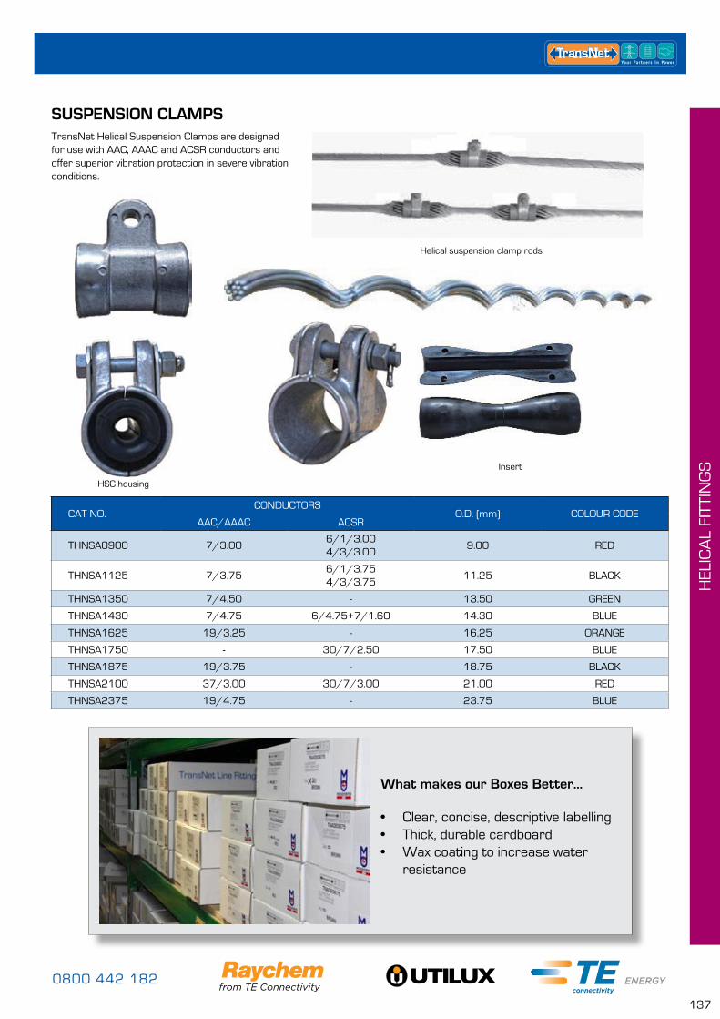
0800 442 182
137
HEL
ICA
L FI
TTIN
GS
CAT NO.CONDUCTORS
O.D. (mm) COLOUR CODEAAC/AAAC ACSR
THNSA0900 7/3.006/1/3.004/3/3.00
9.00 RED
THNSA1125 7/3.756/1/3.754/3/3.75
11.25 BLACK
THNSA1350 7/4.50 - 13.50 GREEN
THNSA1430 7/4.75 6/4.75+7/1.60 14.30 BLUE
THNSA1625 19/3.25 - 16.25 ORANGE
THNSA1750 - 30/7/2.50 17.50 BLUE
THNSA1875 19/3.75 - 18.75 BLACK
THNSA2100 37/3.00 30/7/3.00 21.00 RED
THNSA2375 19/4.75 - 23.75 BLUE
SUSPENSION CLAMPSTransNet Helical Suspension Clamps are designed for use with AAC, AAAC and ACSR conductors and offer superior vibration protection in severe vibration conditions.
HSC housing
Insert
Helical suspension clamp rods
What makes our Boxes Better...
• Clear, concise, descriptive labelling• Thick, durable cardboard• Wax coating to increase water
resistance
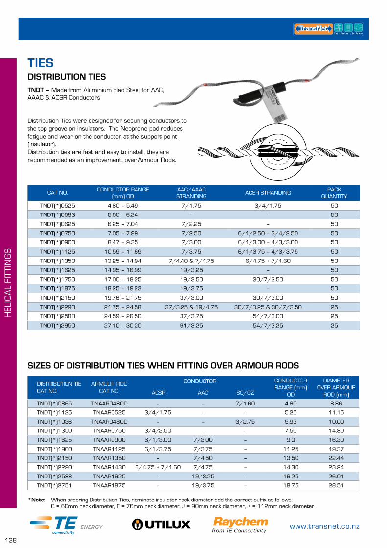
www.transnet.co.nz
138
HEL
ICA
L FI
TTIN
GS
DISTRIBUTION TIESTNDT – Made from Aluminium clad Steel for AAC, AAAC & ACSR Conductors
Distribution Ties were designed for securing conductors to the top groove on insulators. The Neoprene pad reduces fatigue and wear on the conductor at the support point (insulator). Distribution ties are fast and easy to install, they are recommended as an improvement, over Armour Rods.
CAT NO.CONDUCTOR RANGE
(mm) ODAAC/AAAC STRANDING
ACSR STRANDINGPACK
QUANTITY
TNDT(*)0525 4.80 – 5.49 7/1.75 3/4/1.75 50
TNDT(*)0593 5.50 – 6.24 – – 50
TNDT(*)0625 6.25 – 7.04 7/2.25 – 50
TNDT(*)0750 7.05 – 7.99 7/2.50 6/1/2.50 – 3/4/2.50 50
TNDT(*)0900 8.47 – 9.35 7/3.00 6/1/3.00 – 4/3/3.00 50
TNDT(*)1125 10.59 – 11.69 7/3.75 6/1/3.75 – 4/3/3.75 50
TNDT(*)1350 13.25 – 14.94 7/4.40 & 7/4.75 6/4.75 + 7/1.60 50
TNDT(*)1625 14.95 – 16.99 19/3.25 – 50
TNDT(*)1750 17.00 – 18.25 19/3.50 30/7/2.50 50
TNDT(*)1875 18.25 – 19.23 19/3.75 – 50
TNDT(*)2150 19.76 – 21.75 37/3.00 30/7/3.00 50
TNDT(*)2290 21.75 – 24.58 37/3.25 & 19/4.75 30/7/3.25 & 30/7/3.50 25
TNDT(*)2588 24.59 – 26.50 37/3.75 54/7/3.00 25
TNDT(*)2950 27.10 – 30.20 61/3.25 54/7/3.25 25
SIZES OF DISTRIBUTION TIES WHEN FITTING OVER ARMOUR RODS
DISTRIBUTION TIE CAT NO.
ARMOUR ROD CAT NO.
CONDUCTOR CONDUCTOR RANGE (mm)
OD
DIAMETER OVER ARMOUR
ROD (mm) ACSR AAC SC/GZ
TNDT(*)0865 TNAAR0480D – – 7/1.60 4.80 8.86
TNDT(*)1125 TNAAR0525 3/4/1.75 – – 5.25 11.15
TNDT(*)1036 TNAAR0480D – – 3/2.75 5.93 10.00
TNDT(*)1350 TNAAR0750 3/4/2.50 – – 7.50 14.80
TNDT(*)1625 TNAAR0900 6/1/3.00 7/3.00 – 9.0 16.30
TNDT(*)1900 TNAAR1125 6/1/3.75 7/3.75 – 11.25 19.37
TNDT(*)2150 TNAAR1350 – 7/4.50 – 13.50 22.44
TNDT(*)2290 TNAAR1430 6/4.75 + 7/1.60 7/4.75 – 14.30 23.24
TNDT(*)2588 TNAAR1625 – 19/3.25 – 16.25 26.01
TNDT(*)2751 TNAAR1875 – 19/3.75 – 18.75 28.51
*Note: When ordering Distribution Ties, nominate insulator neck diameter add the correct suffix as follows: C = 60mm neck diameter, F = 76mm neck diameter, J = 90mm neck diameter, K = 112mm neck diameter
TIES
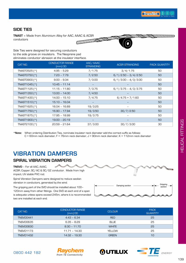
0800 442 182
139
HEL
ICA
L FI
TTIN
GS
TNAST – Made from Aluminium Alloy for AAC, AAAC & ACSR conductors
Side Ties were designed for securing conductors to the side groove on insulators. The Neoprene pad eliminates conductor abrasion at the insulator interface.
SIDE TIES
CAT NO.CONDUCTOR RANGE
(mm) ODAAC/AAAC STRANDING
ACSR STRANDING PACK QUANTITY
TNAST0525 (*) 4.95 – 5.29 7/1.75 3/4/1.75 50
TNAST0750 (*) 7.23 – 7.79 7/2.50 6/1/2.50 – 3/4/2.50 50
TNAST0900 (*) 9.00 – 9.34 7/3.00 6/1/3.00 – 4/3/3.00 50
TNAST1045 (*) 10.45 – 11.14 – – 50
TNAST1125 (*) 11.15 – 11.80 7/3.75 6/1/3.75 – 4/3/3.75 50
TNAST1350 (*) 13.00 – 14.00 7/4.50 – 50
TNAST1430 (*) 14.00 – 15.10 7/4.75 6/4.75 + 7/1.60 50
TNAST1510 (*) 15.10 – 16.04 – – 50
TNAST1625 (*) 16.04 – 16.89 19/3.25 – 50
TNAST1750 (*) 16.90 – 17.94 19/3.50 30/7/2.50 50
TNAST1875 (*) 17.95 – 18.99 19/3.75 – 50
TNAST1900 (*) 19.00 – 20.19 – – 50
TNAST2100 (*) 20.59 – 21.64 37/3.00 30/7/3.00 30
TNSVD – For all AAC, AAAC, ACSR, Copper, SC/AC & SC/GZ conductor. Made from high impact, UV stable PVC rod.
Spiral Vibration Dampers were designed to reduce aeolian vibration in conductors, generated by the wind.
The gripping part of the SVD should be installed about 100–120mm away from other fittings. One SVD at each end of a span is adequate unless spans exceed 245m, where it is recommended two are installed at each end.
CAT NO.CONDUCTOR RANGE
(mm) ODCOLOUR
PACK QUANTITY
TNSVD0441 4.43 – 6.34 RED 25
TNSVD0635 6.35 – 8.29 BLUE 25
TNSVD0830 8.30 – 11.70 WHITE 25
TNSVD1173 11.71 – 14.30 YELLOW 25
TNSVD1432 14.32 – 19.30 GREEN 10
SPIRAL VIBRATION DAMPERS
Damping section Grippingsection
*Note: When ordering Distribution Ties, nominate insulator neck diameter add the correct suffix as follows: C = 60mm neck diameter, F = 76mm neck diameter, J = 90mm neck diameter, K = 112mm neck diameter
VIBRATION DAMPERS
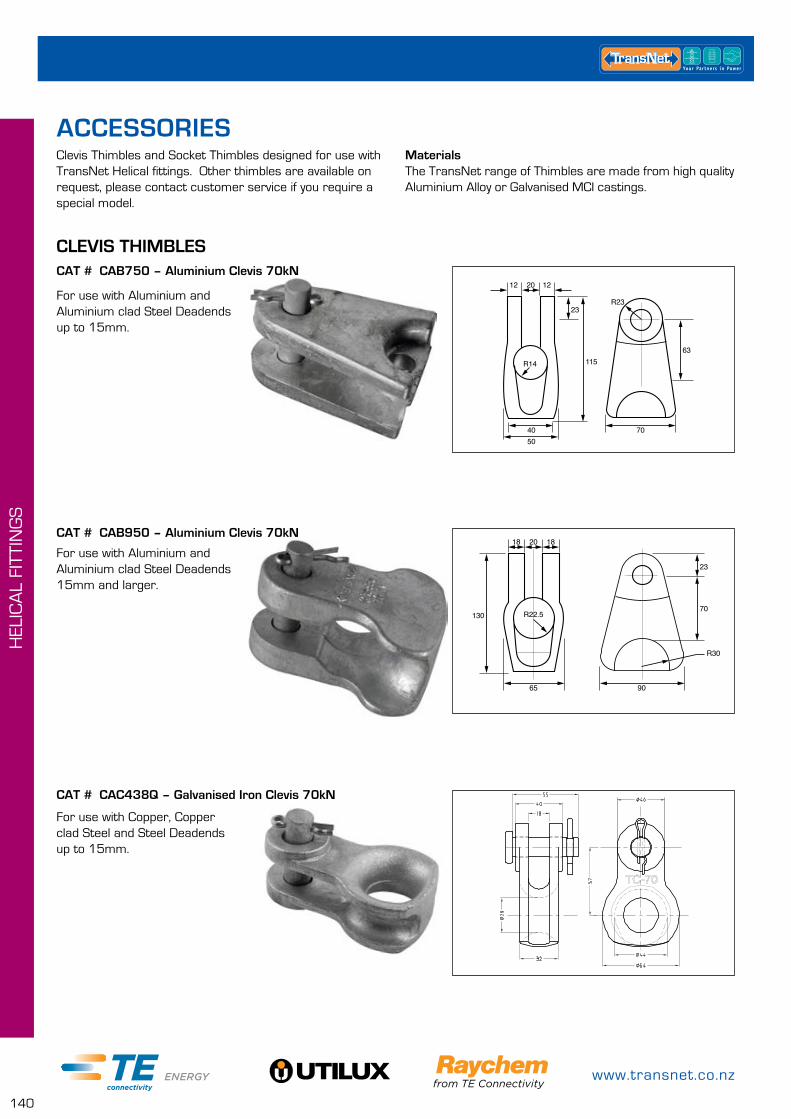
www.transnet.co.nz
140
HEL
ICA
L FI
TTIN
GS
Clevis Thimbles and Socket Thimbles designed for use with TransNet Helical fittings. Other thimbles are available on request, please contact customer service if you require a special model.
CAT # CAB750 – Aluminium Clevis 70kN
CAT # CAB950 – Aluminium Clevis 70kN
R14
R2323
115
2012 12
705040
63
65
2018 18
130
23
R22.5
R30
70
90
For use with Aluminium and Aluminium clad Steel Deadends up to 15mm.
For use with Aluminium and Aluminium clad Steel Deadends 15mm and larger.
CAT # CAC438Q – Galvanised Iron Clevis 70kN
For use with Copper, Copper clad Steel and Steel Deadends up to 15mm.
MaterialsThe TransNet range of Thimbles are made from high quality Aluminium Alloy or Galvanised MCI castings.
ACCESSORIES
CLEVIS THIMBLES
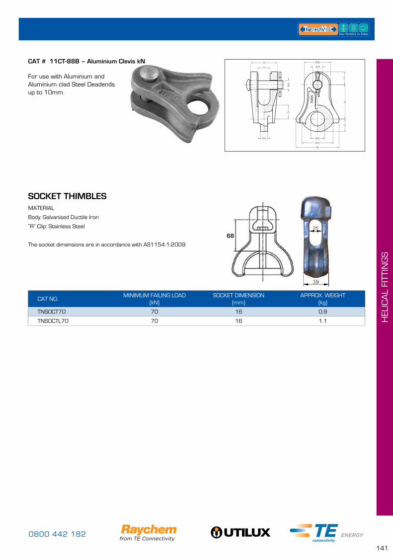
0800 442 182
141
HEL
ICA
L FI
TTIN
GS
CAT # 11CT-88B – Aluminium Clevis kN
70KN
For use with Aluminium and Aluminium clad Steel Deadends up to 10mm.
CAT NO.MINIMUM FAILING LOAD
(kN)SOCKET DIMENSION
(mm)APPROX. WEIGHT
(kg)
TNSOCT70 70 16 0.9
TNSOCTL70 70 16 1.1
SOCKET THIMBLESMATERIAL
Body: Galvanised Ductile Iron
“R” Clip: Stainless Steel
The socket dimensions are in accordance with AS1154.1:2009
68
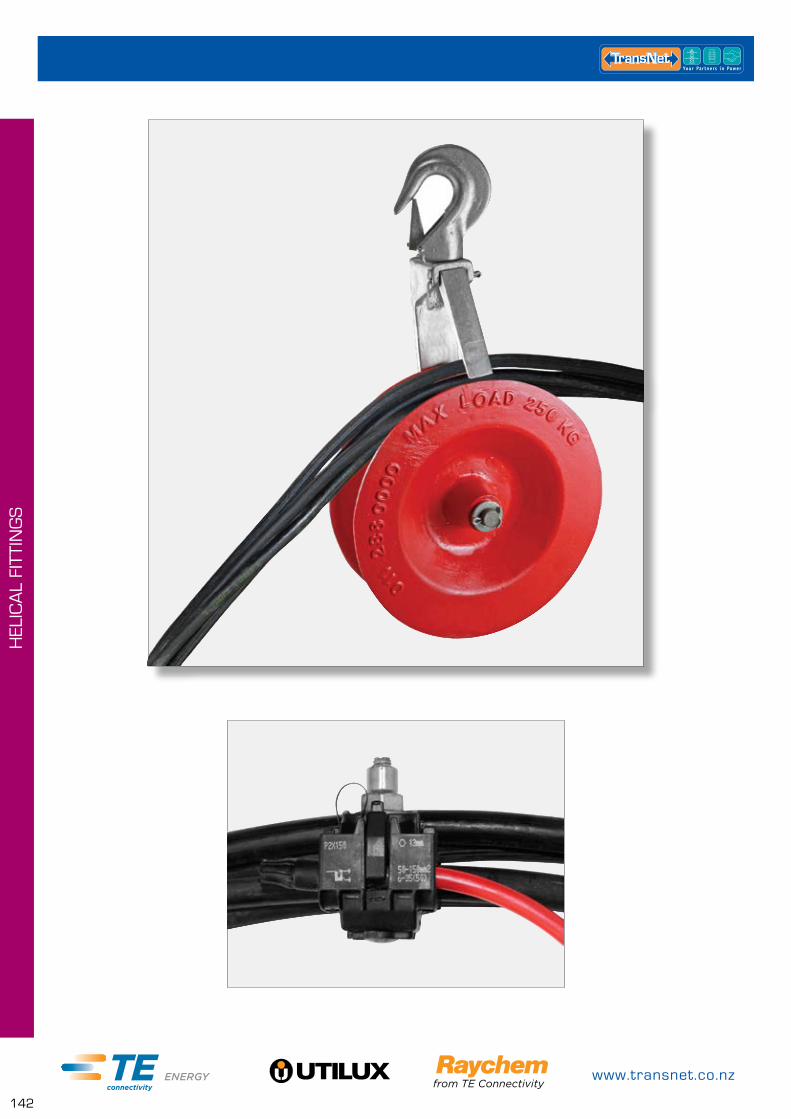
www.transnet.co.nz
142
HEL
ICA
L FI
TTIN
GS
0800 442 182
143
LV A
BC
PR
OD
UC
TS
ABC CONNECTORS PAGE
Pre-Insulated Compressioin Connectors – Lugs & Links 144
IPC's – Insulation Piercing Connectors 145
END CAPS PAGE
Push On End Cap 145
Heatshrinkable End Cap 146
HOUSE CONNECTION PAGE
Mains Entry Box 146
House Hook 147
Service Clamps 147
LV ABC Bolted Clamps 147
NETWORK CONNECTION PAGE
Tension Clamps 148
Suspension Clamps 148
Double Suspension Yoke Bracket 149
Hook Bolts 149
Hook Nuts 149
Hook Brackets 150
Weak Links 150
Eye Nuts 150
ABC TOOLS PAGE
LV ABC Separating Wedges 151
ABC Installation Pulley 151
ABC Pulling Sock 151
Insulated IPC Ratchet Spanner 152
Swivel 152
ABC Wire Grip 152
LV ABC PRODUCTS
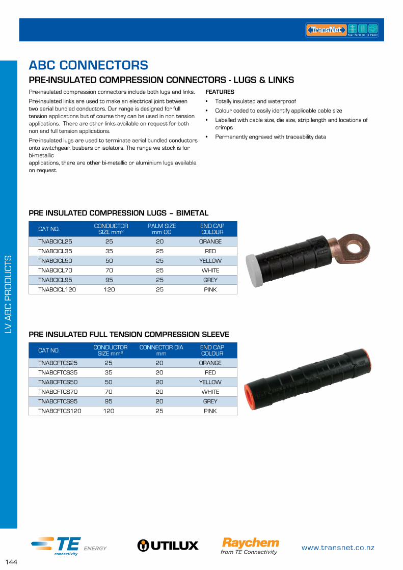
www.transnet.co.nz
144
LV A
BC
PR
OD
UC
TS
ABC CONNECTORSPRE-INSULATED COMPRESSION CONNECTORS - LUGS & LINKSPre-insulated compression connectors include both lugs and links.
Pre-insulated links are used to make an electrical joint between two aerial bundled conductors. Our range is designed for full tension applications but of course they can be used in non tension applications. There are other links available on request for both non and full tension applications.
Pre-insulated lugs are used to terminate aerial bundled conductors onto switchgear, busbars or isolators. The range we stock is for bi-metallic applications, there are other bi-metallic or aluminium lugs available on request.
CAT NO. CONDUCTOR SIZE mm²
PALM SIZE mm OD
END CAP COLOUR
TNABCICL25 25 20 ORANGE
TNABCICL35 35 25 RED
TNABCICL50 50 25 YELLOW
TNABCICL70 70 25 WHITE
TNABCICL95 95 25 GREY
TNABCICL120 120 25 PINK
CAT NO. CONDUCTOR SIZE mm²
CONNECTOR DIA mm
END CAP COLOUR
TNABCFTCS25 25 20 ORANGE
TNABCFTCS35 35 20 RED
TNABCFTCS50 50 20 YELLOW
TNABCFTCS70 70 20 WHITE
TNABCFTCS95 95 20 GREY
TNABCFTCS120 120 25 PINK
PRE INSULATED COMPRESSION LUGS – BIMETAL
PRE INSULATED FULL TENSION COMPRESSION SLEEVE
FEATURES
• Totally insulated and waterproof
• Colour coded to easily identify applicable cable size
• Labelled with cable size, die size, strip length and locations of crimps
• Permanently engraved with traceability data
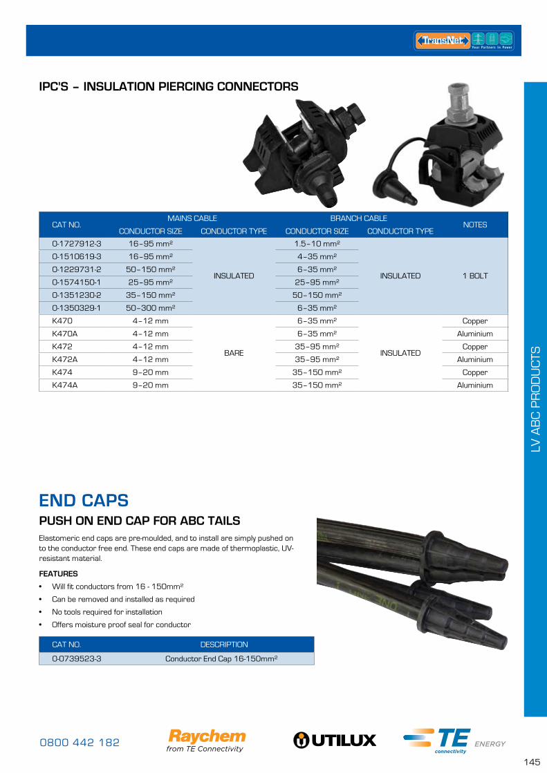
0800 442 182
145
LV A
BC
PR
OD
UC
TS
END CAPS
Elastomeric end caps are pre-moulded, and to install are simply pushed on to the conductor free end. These end caps are made of thermoplastic, UV-resistant material.
FEATURES
• Will fit conductors from 16 - 150mm²
• Can be removed and installed as required
• No tools required for installation
• Offers moisture proof seal for conductor
CAT NO. DESCRIPTION
0-0739523-3 Conductor End Cap 16-150mm²
PUSH ON END CAP FOR ABC TAILS
IPC'S – INSULATION PIERCING CONNECTORS
CAT NO.MAINS CABLE BRANCH CABLE
NOTESCONDUCTOR SIZE CONDUCTOR TYPE CONDUCTOR SIZE CONDUCTOR TYPE
0-1727912-3 16–95 mm²
INSULATED
1.5–10 mm²
INSULATED 1 BOLT
0-1510619-3 16–95 mm² 4–35 mm²
0-1229731-2 50–150 mm² 6–35 mm²
0-1574150-1 25–95 mm² 25–95 mm²
0-1351230-2 35–150 mm² 50–150 mm²
0-1350329-1 50–300 mm² 6–35 mm²
K470 4–12 mm
BARE
6–35 mm²
INSULATED
Copper
K470A 4–12 mm 6–35 mm² Aluminium
K472 4–12 mm 35–95 mm² Copper
K472A 4–12 mm 35–95 mm² Aluminium
K474 9–20 mm 35–150 mm² Copper
K474A 9–20 mm 35–150 mm² Aluminium
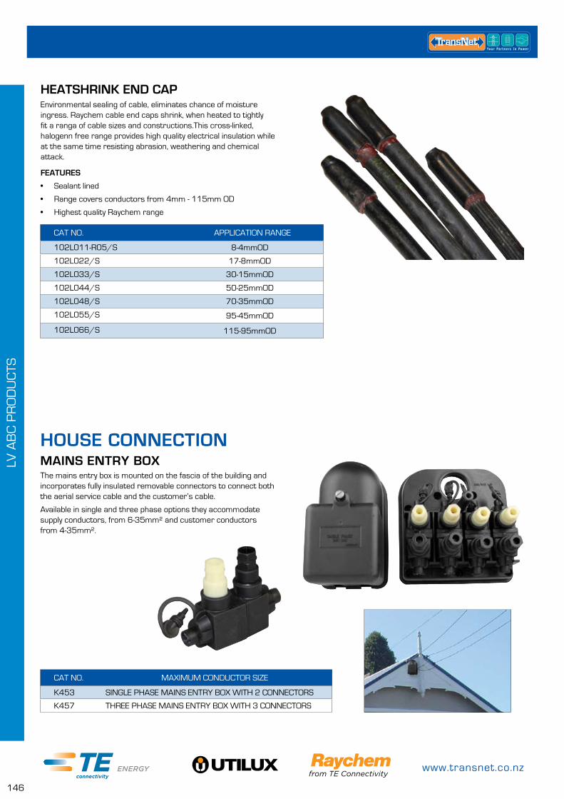
www.transnet.co.nz
146
LV A
BC
PR
OD
UC
TS
CAT NO. MAXIMUM CONDUCTOR SIZE
K453 SINGLE PHASE MAINS ENTRY BOX WITH 2 CONNECTORS
K457 THREE PHASE MAINS ENTRY BOX WITH 3 CONNECTORS
MAINS ENTRY BOXThe mains entry box is mounted on the fascia of the building and incorporates fully insulated removable connectors to connect both the aerial service cable and the customer’s cable.
Available in single and three phase options they accommodate supply conductors, from 6-35mm² and customer conductors from 4-35mm².
HOUSE CONNECTION
HEATSHRINK END CAPEnvironmental sealing of cable, eliminates chance of moisture ingress. Raychem cable end caps shrink, when heated to tightly fit a ranga of cable sizes and constructions.This cross-linked, halogenn free range provides high quality electrical insulation while at the same time resisting abrasion, weathering and chemical attack.
FEATURES
• Sealant lined
• Range covers conductors from 4mm - 115mm OD
• Highest quality Raychem range
CAT NO. APPLICATION RANGE
102L011-R05/S 8-4mmOD
102L022/S 17-8mmOD
102L033/S 30-15mmOD
102L044/S 50-25mmOD
102L048/S 70-35mmOD
102L055/S 95-45mmOD
102L066/S 115-95mmOD
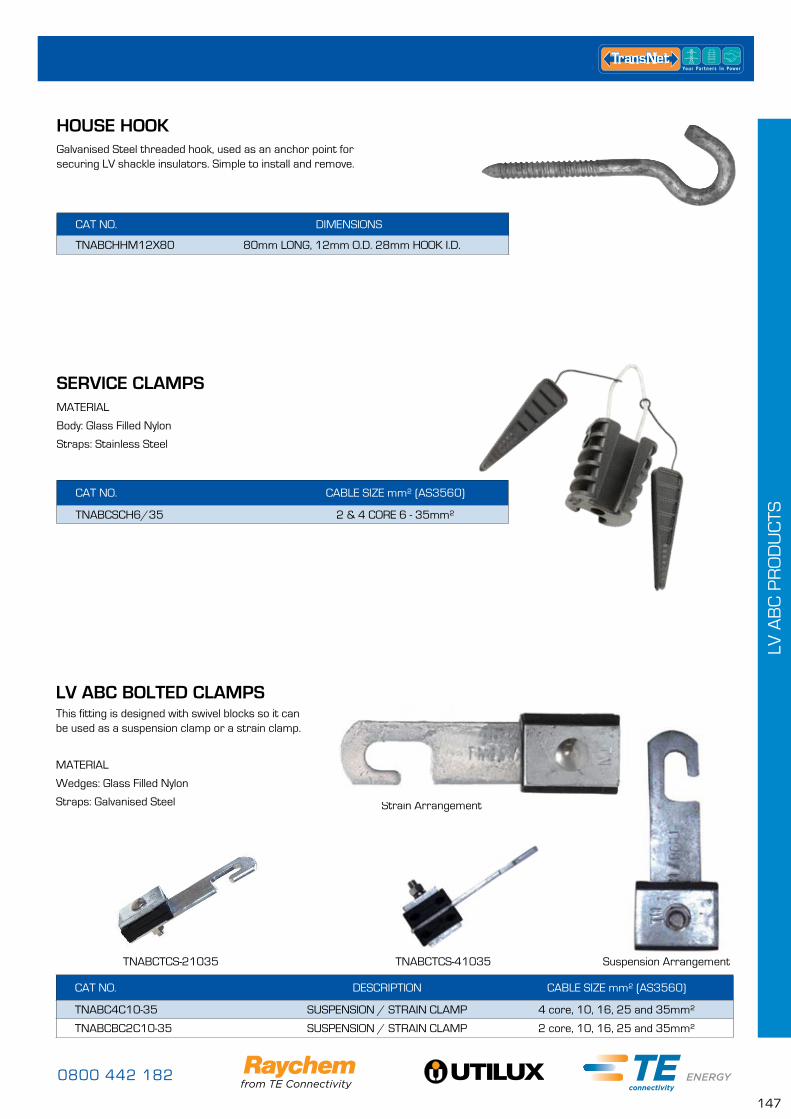
0800 442 182
147
LV A
BC
PR
OD
UC
TS
CAT NO. DIMENSIONS
TNABCHHM12X80 80mm LONG, 12mm O.D. 28mm HOOK I.D.
Galvanised Steel threaded hook, used as an anchor point for securing LV shackle insulators. Simple to install and remove.
HOUSE HOOK
CAT NO. CABLE SIZE mm² (AS3560)
TNABCSCH6/35 2 & 4 CORE 6 - 35mm²
SERVICE CLAMPSMATERIAL
Body: Glass Filled Nylon
Straps: Stainless Steel
CAT NO. DESCRIPTION CABLE SIZE mm² (AS3560)
TNABC4C10-35 SUSPENSION / STRAIN CLAMP 4 core, 10, 16, 25 and 35mm²
TNABCBC2C10-35 SUSPENSION / STRAIN CLAMP 2 core, 10, 16, 25 and 35mm²
LV ABC BOLTED CLAMPSThis fitting is designed with swivel blocks so it can be used as a suspension clamp or a strain clamp.
MATERIAL
Wedges: Glass Filled Nylon
Straps: Galvanised Steel Strain Arrangement
TNABCTCS-21035 TNABCTCS-41035 Suspension Arrangement
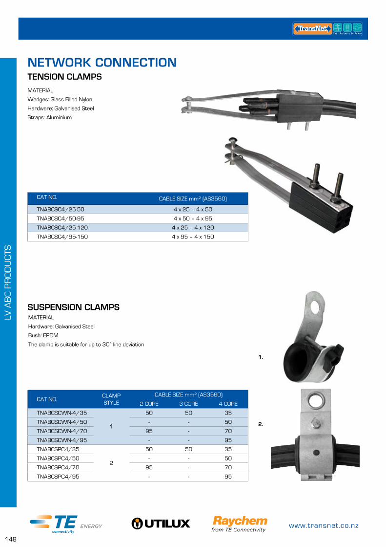
www.transnet.co.nz
148
LV A
BC
PR
OD
UC
TS
TENSION CLAMPSMATERIAL
Wedges: Glass Filled Nylon
Hardware: Galvanised Steel
Straps: Aluminium
CAT NO. CABLE SIZE mm² (AS3560)
TNABCSC4/25-50 4 x 25 – 4 x 50
TNABCSC4/50-95 4 x 50 – 4 x 95
TNABCSC4/25-120 4 x 25 – 4 x 120
TNABCSC4/95-150 4 x 95 – 4 x 150
NETWORK CONNECTION
MATERIAL
Hardware: Galvanised Steel
Bush: EPDM
The clamp is suitable for up to 30° line deviation
SUSPENSION CLAMPS
CAT NO.CLAMP STYLE
CABLE SIZE mm² (AS3560)
2 CORE 3 CORE 4 CORE
TNABCSCWN-4/35
1
50 50 35
TNABCSCWN-4/50 - - 50
TNABCSCWN-4/70 95 - 70
TNABCSCWN-4/95 - - 95
TNABCSPC4/35
2
50 50 35
TNABCSPC4/50 - - 50
TNABCSPC4/70 95 - 70
TNABCSPC4/95 - - 95
1.
2.
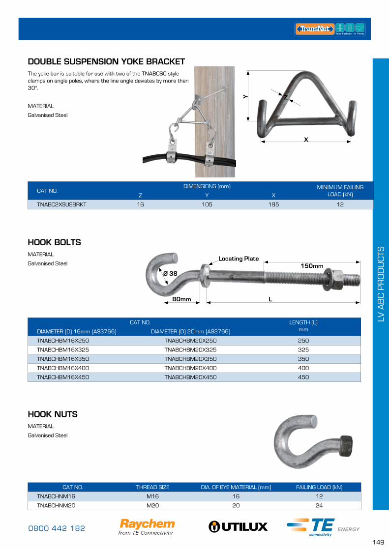
0800 442 182
149
LV A
BC
PR
OD
UC
TS
DOUBLE SUSPENSION YOKE BRACKETThe yoke bar is suitable for use with two of the TNABCSC style clamps on angle poles, where the line angle deviates by more than 30°.
MATERIAL
Galvanised Steel
CAT NO.DIMENSIONS (mm) MINIMUM FAILING
LOAD (kN)Z Y X
TNABC2XSUSBRKT 16 105 195 12
Y
X
Z
CAT NO. LENGTH (L) mmDIAMETER (D) 16mm (AS3766) DIAMETER (D) 20mm (AS3766)
TNABCHBM16X250 TNABCHBM20X250 250
TNABCHBM16X325 TNABCHBM20X325 325
TNABCHBM16X350 TNABCHBM20X350 350
TNABCHBM16X400 TNABCHBM20X400 400
TNABCHBM16X450 TNABCHBM20X450 450
HOOK BOLTSMATERIAL
Galvanised Steel 150mmLocating Plate
80mm
Ø 38
L
CAT NO. THREAD SIZE DIA. OF EYE MATERIAL (mm) FAILING LOAD (kN)
TNABCHNM16 M16 16 12
TNABCHNM20 M20 20 24
HOOK NUTSMATERIAL
Galvanised Steel
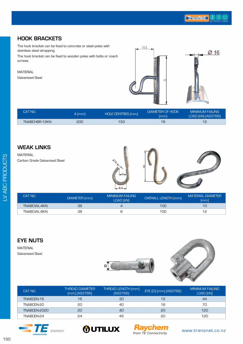
www.transnet.co.nz
150
LV A
BC
PR
OD
UC
TS
WEAK LINKSMATERIAL
Carbon Grade Galvanised Steel
CAT NO.DIAMETER (mm)
MINIMUM FAILING LOAD (kN)
OVERALL LENGTH (mm)MATERIAL DIAMETER
(mm)
TNABCWL-4KN 38 4 100 10
TNABCWL-8KN 38 8 100 12
HOOK BRACKETSThe hook bracket can be fixed to concrete or steel poles with stainless steel strapping.
The hook bracket can be fixed to wooden poles with bolts or coach screws
MATERIAL
Galvanised Steel
CAT NO.A (mm) HOLE CENTRES (mm)
DIAMETER OF HOOK (mm)
MINIMUM FAILING LOAD (kN) (AS3766)
TNABCHBR-12KN 200 150 16 12
EYE NUTSMATERIAL
Galvanised Steel
CAT NO.THREAD DIAMETER
(mm) (AS3766)THREAD LENGTH (mm)
(AS3766)EYE (D) (mm) (AS3766)
MINIMUM FAILING LOAD (kN)
TNABCEN-16 16 30 12 44
TNABCEN-20 20 40 16 70
TNABCEN-2020 20 40 20 120
TNABCEN-24 24 45 20 120
D
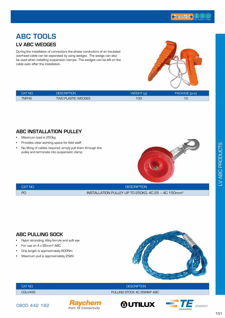
0800 442 182
151
LV A
BC
PR
OD
UC
TS
LV ABC WEDGESDuring the installation of connectors the phase conductors of an insulated overhead cable can be separated by using wedges. The wedge can also be used when installing suspension clamps. The wedges can be left on the cable even after the installation.
CAT NO. DESCRIPTION WEIGHT (g) PACKAGE (pcs)
TNPHS TWO PLASTIC WEDGES 100 10
ABC INSTALLATION PULLEY• Maximum load is 250kg
• Provides clear working space for field staff
• No lifting of cables required, simply pull them through the pulley and terminate into suspension clamp
CAT NO. DESCRIPTION
PO INSTALLATION PULLEY UP TO 250KG, 4C 25 – 4C 150mm²
ABC PULLING SOCK• Nylon stranding, Alloy ferrule and soft eye
• For use on 4 x 95mm² ABC
• Grip length is approximately 800Nm
• Maximum pull is approximately 25kN
CAT NO. DESCRIPTION
CGLV495 PULLING STOCK 4C 95MM² ABC
ABC TOOLS
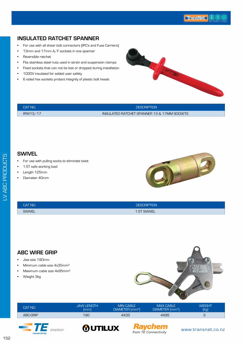
www.transnet.co.nz
152
LV A
BC
PR
OD
UC
TS
SWIVEL
ABC WIRE GRIP
• For use with pulling socks to eliminate twist
• 1.5T safe working load
• Length 125mm
• Diameter 40mm
• Jaw size 190mm
• Minimum cable size 4x35mm²
• Maximum cable size 4x95mm²
• Weight 3kg
INSULATED RATCHET SPANNER• For use with all shear bolt connectors (IPC's and Fuse Carriers)
• 13mm and 17mm A/F sockets in one spanner
• Reversible ratchet
• Fits stainless steel nuts used in strain and suspension clamps
• Fixed sockets that can not be lost or dropped during installation
• 1000V insulated for added user safety
• 6 sided hex sockets protect integrity of plastic bolt heads
CAT NO. DESCRIPTION
IRW13/17 INSULATED RATCHET SPANNER 13 & 17MM SOCKETS
CAT NO. DESCRIPTION
SWIVEL 1.5T SWIVEL
CAT NO. JAW LENGTH (mm)
MIN CABLE DIAMETER (mm²)
MAX CABLE DIAMETER (mm²)
WEIGHT (kg)
ABC-GRIP 190 4X35 4X95 3
0800 442 182
153
HV
AB
C P
RO
DU
CTS
HV ABC RESTRAINTS PAGE
Helical Bundle Restraints 155
HV ABC SUSPENSION SET UP PAGE
Suspension Bracket 156
Hook Bolt 156
Suspension Clamps 156
HV ABC STRINGING EQUIPMENT PAGE
HV ABC Roller 157
Rat Strap 157
Yoke Bar 157
Installation Pulley 157
Swivels 158
Cable Pulling Socks 158
HV ABC PRODUCTS
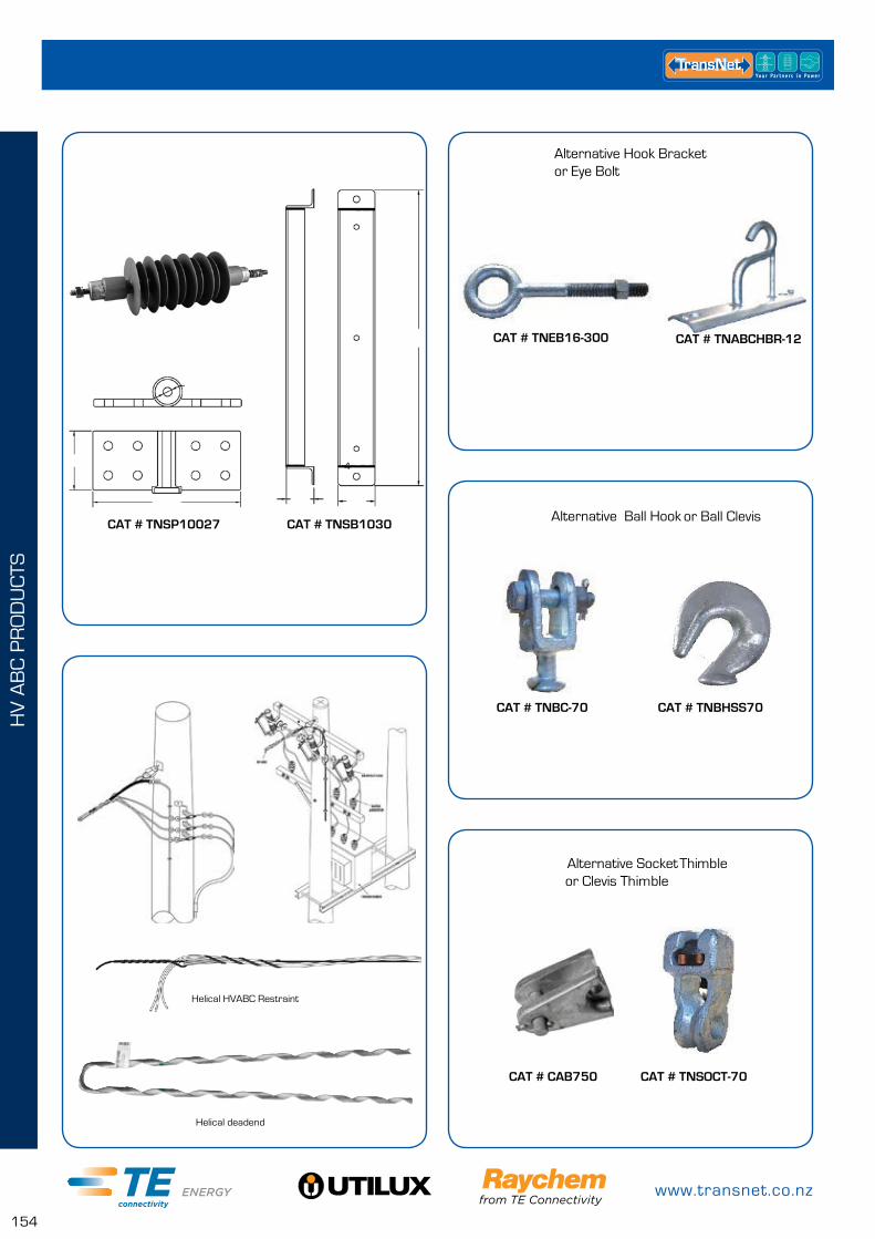
www.transnet.co.nz
154
HV
AB
C P
RO
DU
CTS
CAT NO. CTNSP10027 CAT NO. CTNSB1030
4
CTNEB16-300 CTNABCHBR-12
Alternative Hook Bracketor Eye Bolt
CTNBC-70 CTNBH-LS-70
Alternative Socket Thimble or Clevis Thimble
Alternative Ball Hook or Ball Clevis
CTNCAB-750
Helical HVABC Restraint
Helical deadend
CTNSOCT-70
CAT # TNSP10027 CAT # TNSB1030
CAT # CAB750 CAT # TNSOCT-70
CAT # TNBC-70
CAT # TNEB16-300 CAT # TNABCHBR-12
CAT # TNBHSS70
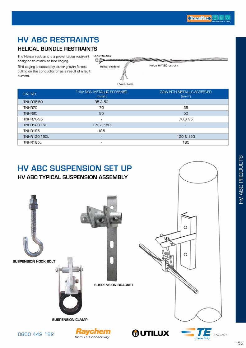
0800 442 182
155
HV
AB
C P
RO
DU
CTS
Socket thimble
Helical deadend
HVABC cable
Helical HVABC restraint
HELICAL BUNDLE RESTRAINTS
HV ABC TYPICAL SUSPENSION ASSEMBLY
The Helical restraint is a preventative restraint designed to minimise bird caging.
Bird caging is caused by either gravity forces pulling on the conductor or as a result of a fault current.
CAT NO.11kV NON METALLIC SCREENED
(mm²)22kV NON METALLIC SCREENED
(mm²)
TNHR35-50 35 & 50 -
TNHR70 70 35
TNHR95 95 50
TNHR70-95 - 70 & 95
TNHR120-150 120 & 150 -
TNHR185 185 -
TNHR120-150L - 120 & 150
TNHR185L - 185
HV ABC SUSPENSION SET UP
HV ABC RESTRAINTS
SUSPENSION HOOK BOLT
SUSPENSION CLAMP
SUSPENSION BRACKET
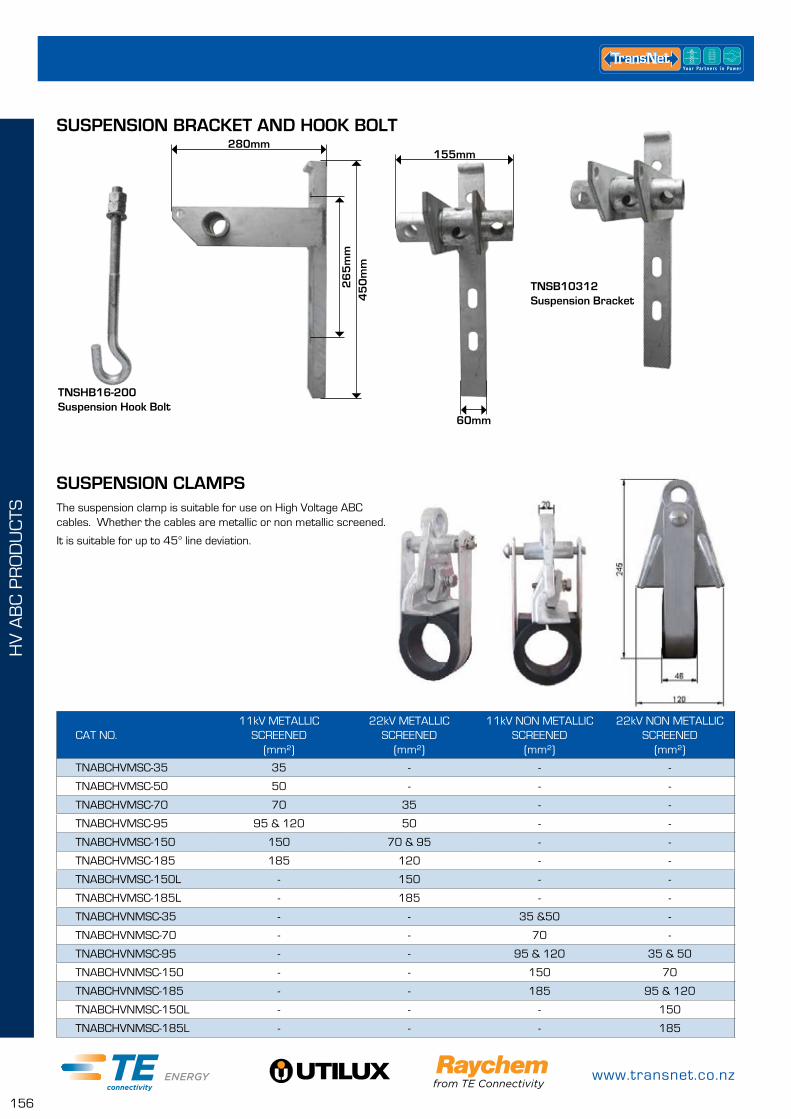
www.transnet.co.nz
156
HV
AB
C P
RO
DU
CTS
t
SUSPENSION CLAMPS
SUSPENSION BRACKET AND HOOK BOLT
The suspension clamp is suitable for use on High Voltage ABC cables. Whether the cables are metallic or non metallic screened.
It is suitable for up to 45° line deviation.
CAT NO.11kV METALLIC
SCREENED (mm²)
22kV METALLIC SCREENED
(mm²)
11kV NON METALLIC SCREENED
(mm²)
22kV NON METALLIC SCREENED
(mm²)
TNABCHVMSC-35 35 - - -
TNABCHVMSC-50 50 - - -
TNABCHVMSC-70 70 35 - -
TNABCHVMSC-95 95 & 120 50 - -
TNABCHVMSC-150 150 70 & 95 - -
TNABCHVMSC-185 185 120 - -
TNABCHVMSC-150L - 150 - -
TNABCHVMSC-185L - 185 - -
TNABCHVNMSC-35 - - 35 &50 -
TNABCHVNMSC-70 - - 70 -
TNABCHVNMSC-95 - - 95 & 120 35 & 50
TNABCHVNMSC-150 - - 150 70
TNABCHVNMSC-185 - - 185 95 & 120
TNABCHVNMSC-150L - - - 150
TNABCHVNMSC-185L - - - 185
60mm
155mm280mm
45
0m
m2
65
mm
TNSB10312Suspension Bracket
TNSHB16-200Suspension Hook Bolt
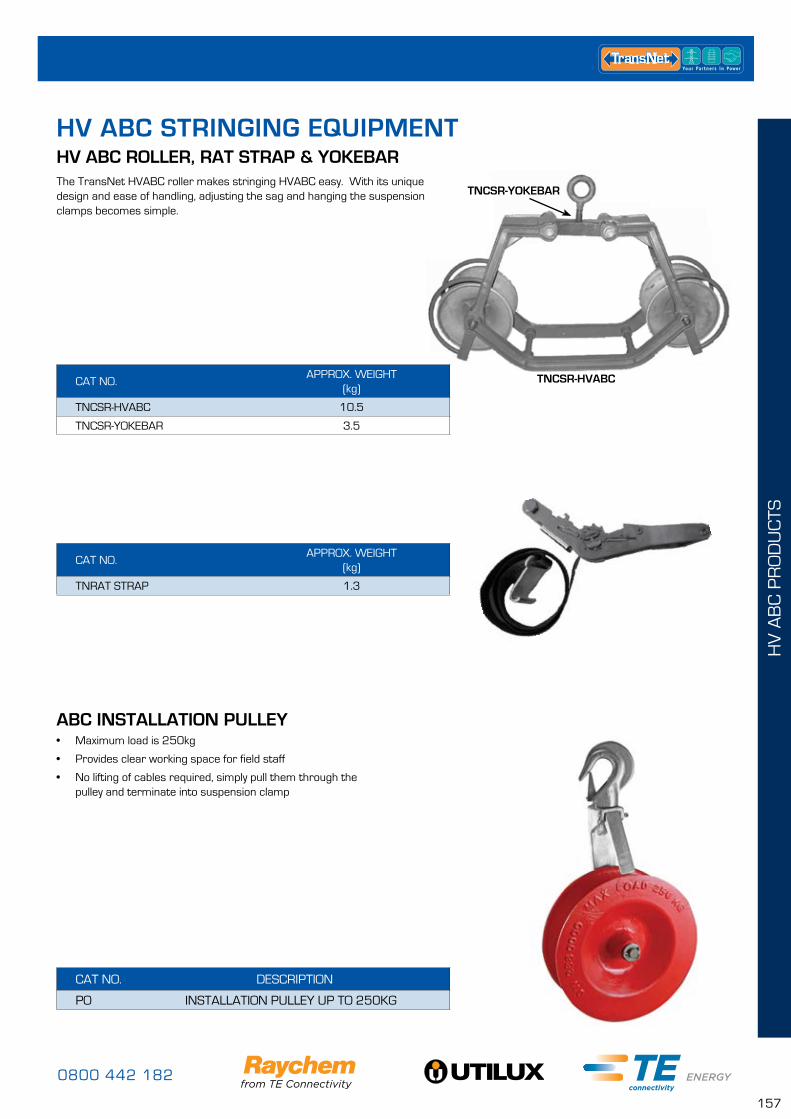
0800 442 182
157
HV
AB
C P
RO
DU
CTS
HV ABC ROLLER, RAT STRAP & YOKEBAR
CAT NO.APPROX. WEIGHT
(kg)
TNCSR-HVABC 10.5
TNCSR-YOKEBAR 3.5
CAT NO.APPROX. WEIGHT
(kg)
TNRAT STRAP 1.3
HV ABC STRINGING EQUIPMENT
ABC INSTALLATION PULLEY• Maximum load is 250kg
• Provides clear working space for field staff
• No lifting of cables required, simply pull them through the pulley and terminate into suspension clamp
CAT NO. DESCRIPTION
PO INSTALLATION PULLEY UP TO 250KG
TNCSR-YOKEBAR
TNCSR-HVABC
The TransNet HVABC roller makes stringing HVABC easy. With its unique design and ease of handling, adjusting the sag and hanging the suspension clamps becomes simple.
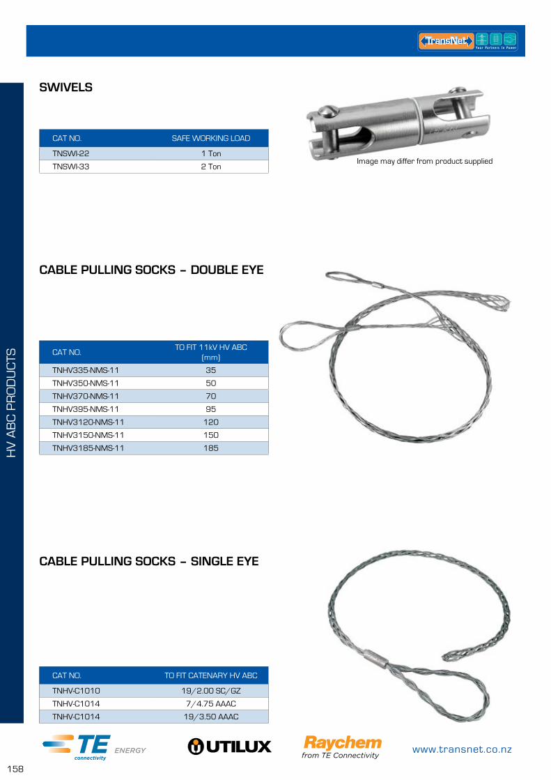
www.transnet.co.nz
158
HV
AB
C P
RO
DU
CTS
CAT NO. SAFE WORKING LOAD
TNSWI-22 1 Ton
TNSWI-33 2 Ton
CAT NO. TO FIT CATENARY HV ABC
TNHV-C1010 19/2.00 SC/GZ
TNHV-C1014 7/4.75 AAAC
TNHV-C1014 19/3.50 AAAC
CAT NO.TO FIT 11kV HV ABC
(mm)
TNHV335-NMS-11 35
TNHV350-NMS-11 50
TNHV370-NMS-11 70
TNHV395-NMS-11 95
TNHV3120-NMS-11 120
TNHV3150-NMS-11 150
TNHV3185-NMS-11 185
SWIVELS
CABLE PULLING SOCKS – DOUBLE EYE
CABLE PULLING SOCKS – SINGLE EYE
Image may differ from product supplied
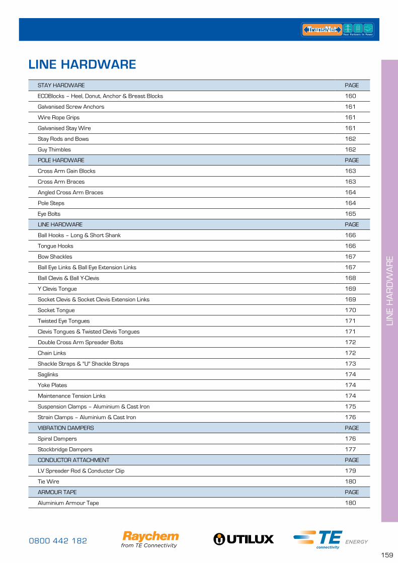
0800 442 182
159
LIN
E H
AR
DW
AR
E
STAY HARDWARE PAGE
ECOBlocks – Heel, Donut, Anchor & Breast Blocks 160
Galvanised Screw Anchors 161
Wire Rope Grips 161
Galvanised Stay Wire 161
Stay Rods and Bows 162
Guy Thimbles 162
POLE HARDWARE PAGE
Cross Arm Gain Blocks 163
Cross Arm Braces 163
Angled Cross Arm Braces 164
Pole Steps 164
Eye Bolts 165
LINE HARDWARE PAGE
Ball Hooks – Long & Short Shank 166
Tongue Hooks 166
Bow Shackles 167
Ball Eye Links & Ball Eye Extension Links 167
Ball Clevis & Ball Y-Clevis 168
Y Clevis Tongue 169
Socket Clevis & Socket Clevis Extension Links 169
Socket Tongue 170
Twisted Eye Tongues 171
Clevis Tongues & Twisted Clevis Tongues 171
Double Cross Arm Spreader Bolts 172
Chain Links 172
Shackle Straps & "U" Shackle Straps 173
Saglinks 174
Yoke Plates 174
Maintenance Tension Links 174
Suspension Clamps – Aluminium & Cast Iron 175
Strain Clamps – Aluminium & Cast Iron 176
VIBRATION DAMPERS PAGE
Spiral Dampers 176
Stockbridge Dampers 177
CONDUCTOR ATTACHMENT PAGE
LV Spreader Rod & Conductor Clip 179
Tie Wire 180
ARMOUR TAPE PAGE
Aluminium Armour Tape 180
LINE HARDWARE
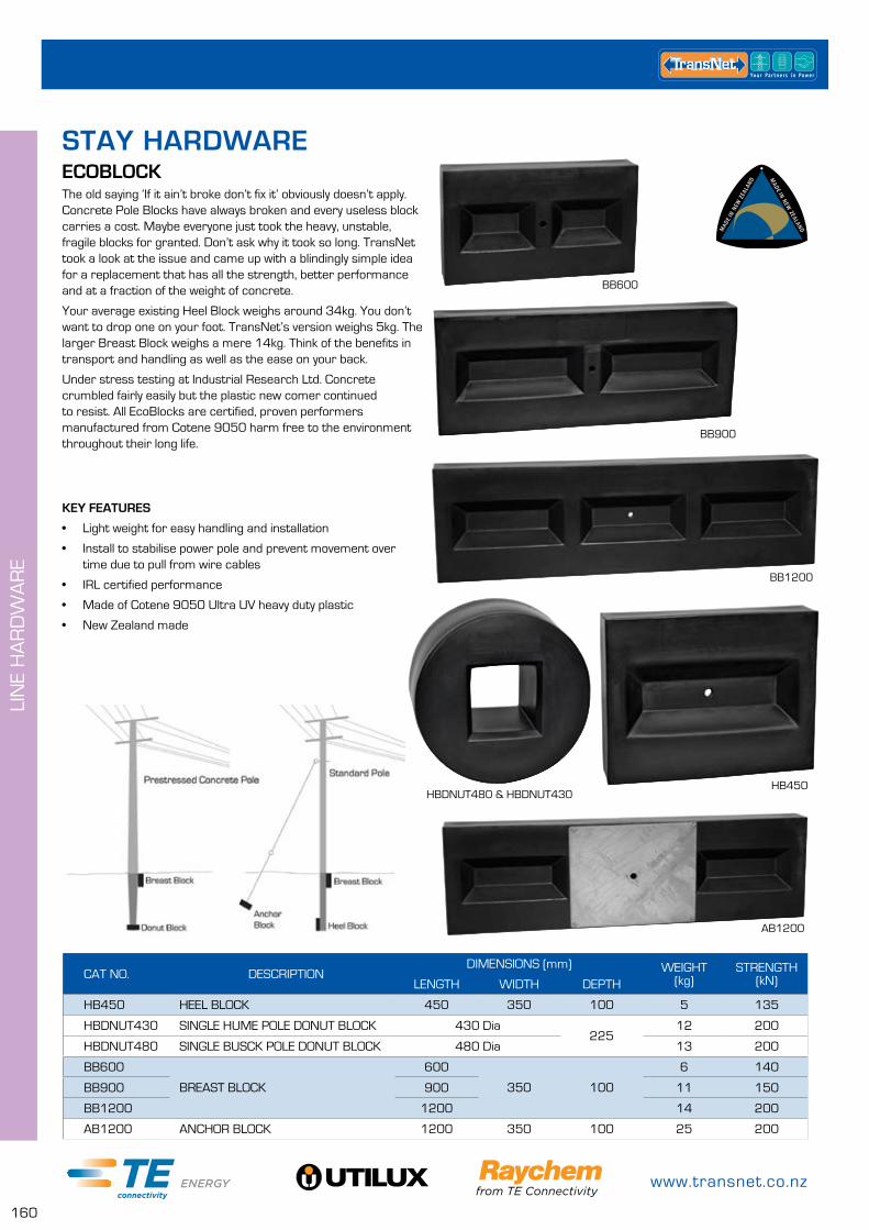
www.transnet.co.nz
160
LIN
E H
AR
DW
AR
E
The old saying ‘If it ain’t broke don’t fix it’ obviously doesn’t apply. Concrete Pole Blocks have always broken and every useless block carries a cost. Maybe everyone just took the heavy, unstable, fragile blocks for granted. Don’t ask why it took so long. TransNet took a look at the issue and came up with a blindingly simple idea for a replacement that has all the strength, better performance and at a fraction of the weight of concrete.
Your average existing Heel Block weighs around 34kg. You don’t want to drop one on your foot. TransNet’s version weighs 5kg. The larger Breast Block weighs a mere 14kg. Think of the benefits in transport and handling as well as the ease on your back.
Under stress testing at Industrial Research Ltd. Concrete crumbled fairly easily but the plastic new comer continued to resist. All EcoBlocks are certified, proven performers manufactured from Cotene 9050 harm free to the environment throughout their long life.
ECOBLOCK
KEY FEATURES
• Light weight for easy handling and installation
• Install to stabilise power pole and prevent movement over time due to pull from wire cables
• IRL certified performance
• Made of Cotene 9050 Ultra UV heavy duty plastic
• New Zealand made
CAT NO. DESCRIPTIONDIMENSIONS (mm) WEIGHT
(kg)STRENGTH
(kN)LENGTH WIDTH DEPTH
HB450 HEEL BLOCK 450 350 100 5 135
HBDNUT430 SINGLE HUME POLE DONUT BLOCK 430 Dia225
12 200
HBDNUT480 SINGLE BUSCK POLE DONUT BLOCK 480 Dia 13 200
BB600
BREAST BLOCK
600
350 100
6 140
BB900 900 11 150
BB1200 1200 14 200
AB1200 ANCHOR BLOCK 1200 350 100 25 200
BB600
BB900
AB1200
HBDNUT480 & HBDNUT430HB450
BB1200
STAY HARDWARE
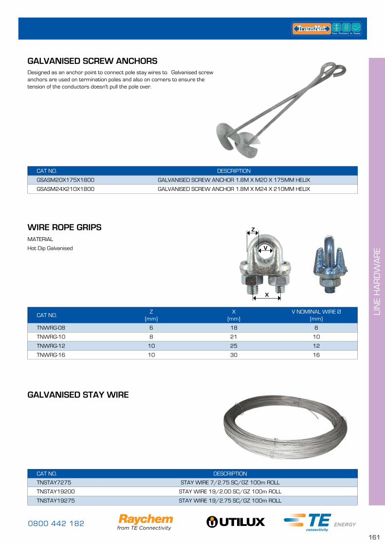
0800 442 182
161
LIN
E H
AR
DW
AR
E
CAT NO. DESCRIPTION
GSASM20X175X1800 GALVANISED SCREW ANCHOR 1.8M X M20 X 175MM HELIX
GSASM24X210X1800 GALVANISED SCREW ANCHOR 1.8M X M24 X 210MM HELIX
Designed as an anchor point to connect pole stay wires to. Galvanised screw anchors are used on termination poles and also on corners to ensure the tension of the conductors doesn't pull the pole over.
GALVANISED SCREW ANCHORS
CAT NO.Z
(mm)X
(mm)V NOMINAL WIRE Ø
(mm)
TNWRG-08 6 18 8
TNWRG-10 8 21 10
TNWRG-12 10 25 12
TNWRG-16 10 30 16
WIRE ROPE GRIPSMATERIAL
Hot Dip Galvanised
X
Z
V
GALVANISED STAY WIRE
CAT NO. DESCRIPTION
TNSTAY7275 STAY WIRE 7/2.75 SC/GZ 100m ROLL
TNSTAY19200 STAY WIRE 19/2.00 SC/GZ 100m ROLL
TNSTAY19275 STAY WIRE 19/2.75 SC/GZ 100m ROLL
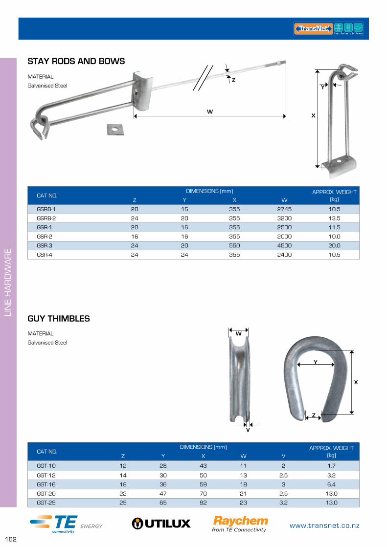
www.transnet.co.nz
162
LIN
E H
AR
DW
AR
E
CAT NO.DIMENSIONS (mm) APPROX. WEIGHT
(kg)Z Y X W
GSRB-1 20 16 355 2745 10.5
GSRB-2 24 20 355 3200 13.5
GSR-1 20 16 355 2500 11.5
GSR-2 16 16 355 2000 10.0
GSR-3 24 20 550 4500 20.0
GSR-4 24 24 355 2400 10.5
STAY RODS AND BOWS
MATERIAL
Galvanised Steel
X
Y
CAT NO.DIMENSIONS (mm) APPROX. WEIGHT
(kg)Z Y X W V
GGT-10 12 28 43 11 2 1.7
GGT-12 14 30 50 13 2.5 3.2
GGT-16 18 36 59 18 3 6.4
GGT-20 22 47 70 21 2.5 13.0
GGT-25 25 65 92 23 3.2 13.0
GUY THIMBLES
MATERIAL
Galvanised Steel
W
V
W
Z
Y
Z
X
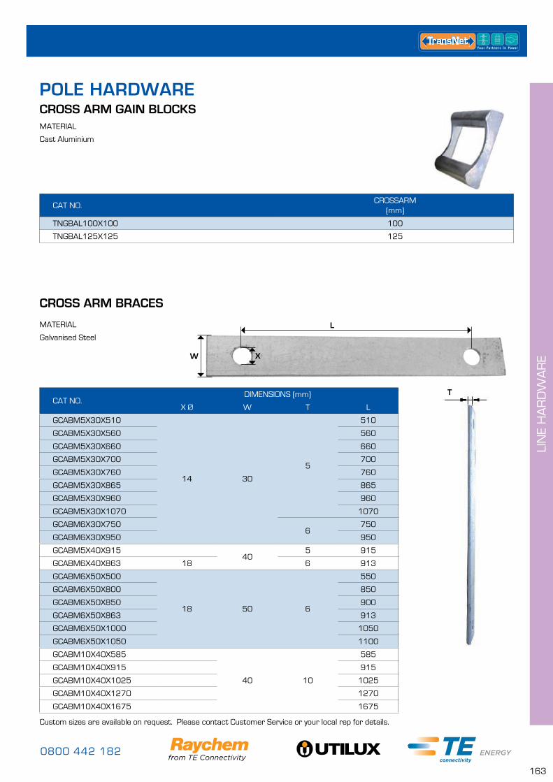
0800 442 182
163
LIN
E H
AR
DW
AR
E
POLE HARDWARE
CAT NO.CROSSARM
(mm)
TNGBAL100X100 100
TNGBAL125X125 125
CROSS ARM GAIN BLOCKSMATERIAL
Cast Aluminium
CAT NO.DIMENSIONS (mm)
X Ø W T L
GCABM5X30X510
14 30
5
510
GCABM5X30X560 560
GCABM5X30X660 660
GCABM5X30X700 700
GCABM5X30X760 760
GCABM5X30X865 865
GCABM5X30X960 960
GCABM5X30X1070 1070
GCABM6X30X7506
750
GCABM6X30X950 950
GCABM5X40X91540
5 915
GCABM6X40X863 18 6 913
GCABM6X50X500
18 50 6
550
GCABM6X50X800 850
GCABM6X50X850 900
GCABM6X50X863 913
GCABM6X50X1000 1050
GCABM6X50X1050 1100
GCABM10X40X585
40 10
585
GCABM10X40X915 915
GCABM10X40X1025 1025
GCABM10X40X1270 1270
GCABM10X40X1675 1675
CROSS ARM BRACES
MATERIAL
Galvanised Steel
L
XW
T
Custom sizes are available on request. Please contact Customer Service or your local rep for details.
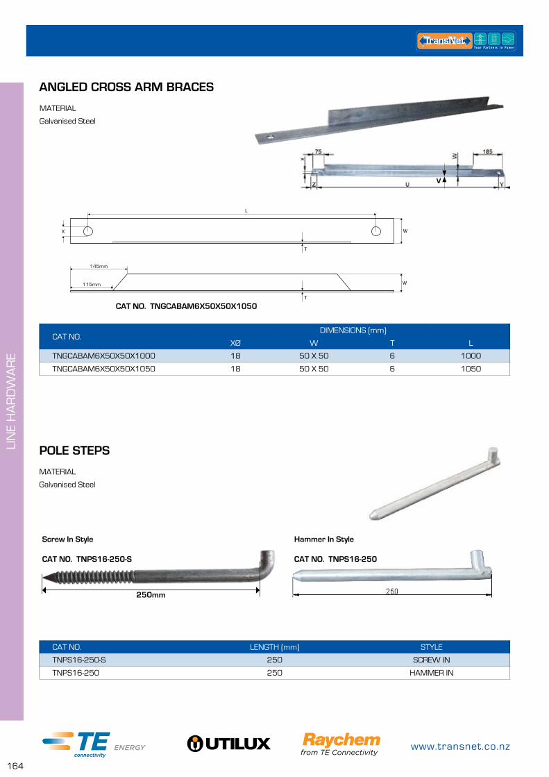
www.transnet.co.nz
164
LIN
E H
AR
DW
AR
E
CAT NO. LENGTH (mm) STYLE
TNPS16-250-S 250 SCREW IN
TNPS16-250 250 HAMMER IN
CAT NO.DIMENSIONS (mm)
XØ W T L
TNGCABAM6X50X50X1000 18 50 X 50 6 1000
TNGCABAM6X50X50X1050 18 50 X 50 6 1050
ANGLED CROSS ARM BRACES
MATERIAL
Galvanised Steel
X W
L
T
W
T
115mm
145mm
V
POLE STEPS
MATERIAL
Galvanised Steel
250mm
Screw In Style
CAT NO. TNPS16-250-S
Hammer In Style
CAT NO. TNPS16-250
CAT NO. TNGCABAM6X50X50X1050
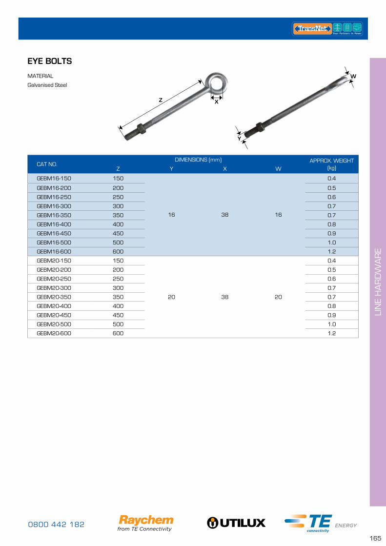
0800 442 182
165
LIN
E H
AR
DW
AR
E
EYE BOLTS
MATERIAL
Galvanised Steel
CAT NO.DIMENSIONS (mm) APPROX. WEIGHT
(kg)Z Y X W
GEBM16-150 150
16 38 16
0.4
GEBM16-200 200 0.5
GEBM16-250 250 0.6
GEBM16-300 300 0.7
GEBM16-350 350 0.7
GEBM16-400 400 0.8
GEBM16-450 450 0.9
GEBM16-500 500 1.0
GEBM16-600 600 1.2
GEBM20-150 150
20 38 20
0.4
GEBM20-200 200 0.5
GEBM20-250 250 0.6
GEBM20-300 300 0.7
GEBM20-350 350 0.7
GEBM20-400 400 0.8
GEBM20-450 450 0.9
GEBM20-500 500 1.0
GEBM20-600 600 1.2
Y
W
Z X
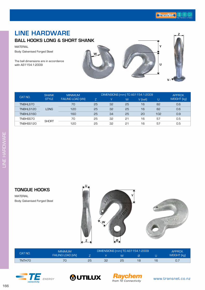
www.transnet.co.nz
166
LIN
E H
AR
DW
AR
E
LINE HARDWARE
TONGUE HOOKSMATERIAL
Body: Galvanised Forged Steel
CAT NO.MINIMUM
FAILING LOAD (kN)DIMENSIONS (mm) TO AS1154.1:2009 APPROX.
WEIGHT (kg)Z Y W Ø U
TNTH70 70 25 32 25 18 16 0.7
Z
U
Ø
Y
W
BALL HOOKS LONG & SHORT SHANKMATERIAL
Body: Galvanised Forged Steel
The ball dimensions are in accordance with AS1154.1:2009
CAT NO.SHANK STYLE
MINIMUM FAILING LOAD (kN)
DIMENSIONS (mm) TO AS1154.1:2009 APPROX. WEIGHT (kg)Z Y W V (ball) U
TNBHLS70
LONG
70 25 32 25 16 82 0.6
TNBHLS120 120 25 32 25 16 82 0.6
TNBHLS160 160 25 34 25 20 102 0.9
TNBHSS70SHORT
70 25 32 21 16 57 0.5
TNBHSS120 120 25 32 21 16 57 0.5
Y
U
W
V
Z
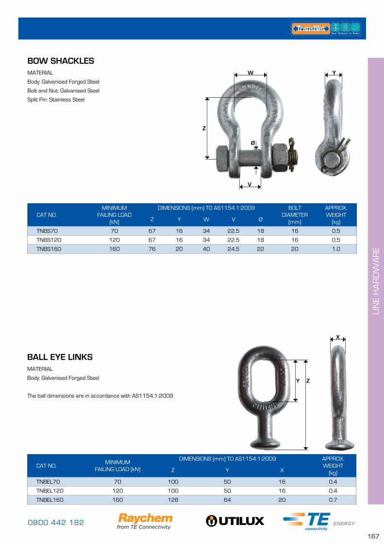
0800 442 182
167
LIN
E H
AR
DW
AR
E
BOW SHACKLESMATERIAL
Body: Galvanised Forged Steel
Bolt and Nut: Galvanised Steel
Split Pin: Stainless Steel
CAT NO.MINIMUM
FAILING LOAD (kN)
DIMENSIONS (mm) TO AS1154.1:2009 BOLT DIAMETER
(mm)
APPROX. WEIGHT
(kg)Z Y W V Ø
TNBS70 70 67 16 34 22.5 18 16 0.5
TNBS120 120 67 16 34 22.5 18 16 0.5
TNBS160 160 76 20 40 24.5 22 20 1.0
YW
Z
Ø
V
BALL EYE LINKSMATERIAL
Body: Galvanised Forged Steel
The ball dimensions are in accordance with AS1154.1:2009
CAT NO.MINIMUM
FAILING LOAD (kN)
DIMENSIONS (mm) TO AS1154.1:2009 APPROX. WEIGHT
(kg)Z Y X
TNBEL70 70 100 50 16 0.4
TNBEL120 120 100 50 16 0.4
TNBEL160 160 128 64 20 0.7
X
Y Z
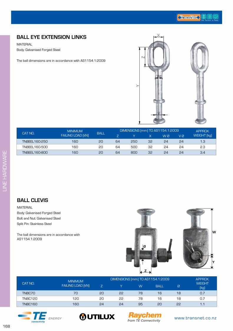
www.transnet.co.nz
168
LIN
E H
AR
DW
AR
E
CAT NO.MINIMUM
FAILING LOAD (kN)
DIMENSIONS (mm) TO AS1154.1:2009 APPROX. WEIGHT
(kg)Z Y W BALL Ø
TNBC70 70 20 22 78 16 18 0.7
TNBC120 120 20 22 78 16 18 0.7
TNBC160 160 24 24 95 20 22 1.1
BALL CLEVISMATERIAL
Body: Galvanised Forged Steel
Bolt and Nut: Galvanised Steel
Split Pin: Stainless Steel
The ball dimensions are in accordance with AS1154.1:2009
W
Y
Z
Ø
BALL EYE EXTENSION LINKSMATERIAL
Body: Galvanised Forged Steel
The ball dimensions are in accordance with AS1154.1:2009
CAT NO.MINIMUM
FAILING LOAD (kN)BALL
DIMENSIONS (mm) TO AS1154.1:2009 APPROX. WEIGHT (kg)Z Y X W Ø V Ø
TNBEEL160-250 160 20 64 250 32 24 24 1.3
TNBEEL160-500 160 20 64 500 32 24 24 2.3
TNBEEL160-800 160 20 64 800 32 24 24 3.4
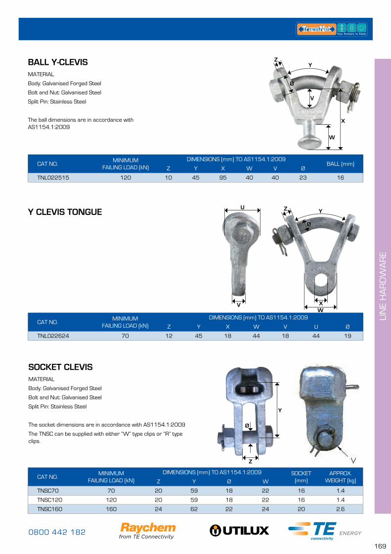
0800 442 182
169
LIN
E H
AR
DW
AR
E
SOCKET CLEVISMATERIAL
Body: Galvanised Forged Steel
Bolt and Nut: Galvanised Steel
Split Pin: Stainless Steel
The socket dimensions are in accordance with AS1154.1:2009
The TNSC can be supplied with either “W” type clips or “R” type clips.
CAT NO.MINIMUM
FAILING LOAD (kN)DIMENSIONS (mm) TO AS1154.1:2009 SOCKET
(mm)APPROX.
WEIGHT (kg)Z Y Ø W
TNSC70 70 20 59 18 22 16 1.4
TNSC120 120 20 59 18 22 16 1.4
TNSC160 160 24 62 22 24 20 2.6
BALL Y-CLEVISMATERIAL
Body: Galvanised Forged Steel
Bolt and Nut: Galvanised Steel
Split Pin: Stainless Steel
The ball dimensions are in accordance with AS1154.1:2009
CAT NO.MINIMUM
FAILING LOAD (kN)DIMENSIONS (mm) TO AS1154.1:2009
BALL (mm)Z Y X W V Ø
TNL022515 120 10 45 95 40 40 23 16
W
X
V
ZY
Ø
Y CLEVIS TONGUE
CAT NO.MINIMUM
FAILING LOAD (kN)DIMENSIONS (mm) TO AS1154.1:2009
Z Y X W V U Ø
TNL022624 70 12 45 18 44 18 44 19
WX
Z Y
Ø
V
U
Z
Y
Ø
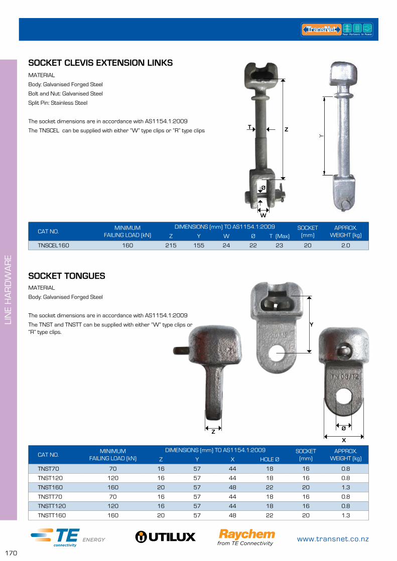
www.transnet.co.nz
170
LIN
E H
AR
DW
AR
E
SOCKET CLEVIS EXTENSION LINKSMATERIAL
Body: Galvanised Forged Steel
Bolt and Nut: Galvanised Steel
Split Pin: Stainless Steel
The socket dimensions are in accordance with AS1154.1:2009
The TNSCEL can be supplied with either “W” type clips or “R” type clips
CAT NO.MINIMUM
FAILING LOAD (kN)DIMENSIONS (mm) TO AS1154.1:2009 SOCKET
(mm)APPROX.
WEIGHT (kg)Z Y W Ø T (Max)
TNSCEL160 160 215 155 24 22 23 20 2.0
SOCKET TONGUESMATERIAL
Body: Galvanised Forged Steel
The socket dimensions are in accordance with AS1154.1:2009
The TNST and TNSTT can be supplied with either “W” type clips or “R” type clips.
CAT NO.MINIMUM
FAILING LOAD (kN)DIMENSIONS (mm) TO AS1154.1:2009 SOCKET
(mm)APPROX.
WEIGHT (kg)Z Y X HOLE Ø
TNST70 70 16 57 44 18 16 0.8
TNST120 120 16 57 44 18 16 0.8
TNST160 160 20 57 48 22 20 1.3
TNSTT70 70 16 57 44 18 16 0.8
TNSTT120 120 16 57 44 18 16 0.8
TNSTT160 160 20 57 48 22 20 1.3
Z
X
Ø
Y
Z
W
Ø
T
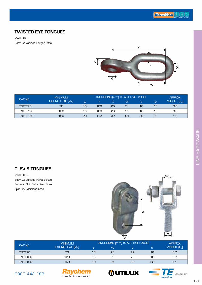
0800 442 182
171
LIN
E H
AR
DW
AR
E
CLEVIS TONGUESMATERIAL
Body: Galvanised Forged Steel
Bolt and Nut: Galvanised Steel
Split Pin: Stainless Steel
CAT NO.MINIMUM
FAILING LOAD (kN)DIMENSIONS (mm) TO AS1154.1:2009 APPROX.
WEIGHT (kg)Y W V Ø
TNCT70 70 16 20 72 18 0.7
TNCT120 120 16 20 72 18 0.7
TNCT160 160 20 24 86 22 1.1
TWISTED EYE TONGUESMATERIAL
Body: Galvanised Forged Steel
CAT NO.MINIMUM
FAILING LOAD (kN)DIMENSIONS (mm) TO AS1154.1:2009 APPROX.
WEIGHT (kg)Z Y X W V Ø
TNTET70 70 16 100 26 51 16 18 0.6
TNTET120 120 16 100 26 51 16 18 0.6
TNTET160 160 20 112 32 64 20 22 1.0
V
Ø
Y
X
VZ
W
Ø
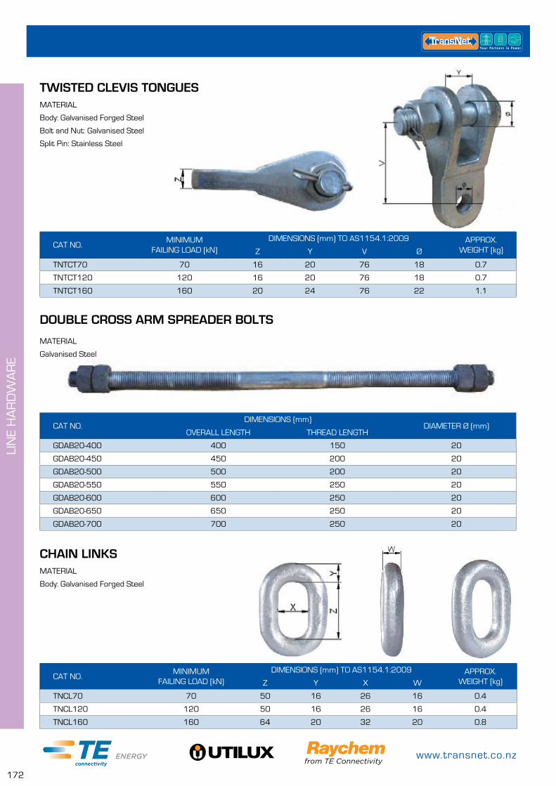
www.transnet.co.nz
172
LIN
E H
AR
DW
AR
E
TWISTED CLEVIS TONGUESMATERIAL
Body: Galvanised Forged Steel
Bolt and Nut: Galvanised Steel
Split Pin: Stainless Steel
CAT NO.MINIMUM
FAILING LOAD (kN)DIMENSIONS (mm) TO AS1154.1:2009 APPROX.
WEIGHT (kg)Z Y V Ø
TNTCT70 70 16 20 76 18 0.7
TNTCT120 120 16 20 76 18 0.7
TNTCT160 160 20 24 76 22 1.1
DOUBLE CROSS ARM SPREADER BOLTS
MATERIAL
Galvanised Steel
CAT NO.DIMENSIONS (mm)
DIAMETER Ø (mm)OVERALL LENGTH THREAD LENGTH
GDAB20-400 400 150 20
GDAB20-450 450 200 20
GDAB20-500 500 200 20
GDAB20-550 550 250 20
GDAB20-600 600 250 20
GDAB20-650 650 250 20
GDAB20-700 700 250 20
CHAIN LINKSMATERIAL
Body: Galvanised Forged Steel
CAT NO.MINIMUM
FAILING LOAD (kN)DIMENSIONS (mm) TO AS1154.1:2009 APPROX.
WEIGHT (kg)Z Y X W
TNCL70 70 50 16 26 16 0.4
TNCL120 120 50 16 26 16 0.4
TNCL160 160 64 20 32 20 0.8
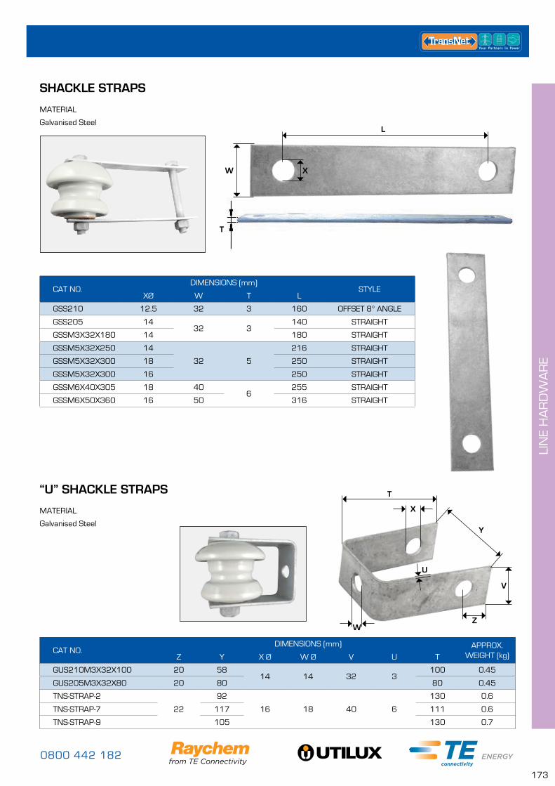
0800 442 182
173
LIN
E H
AR
DW
AR
E
SHACKLE STRAPS
MATERIAL
Galvanised SteelL
W
T
X
CAT NO.DIMENSIONS (mm)
STYLEXØ W T L
GSS210 12.5 32 3 160 OFFSET 8° ANGLE
GSS205 1432 3
140 STRAIGHT
GSSM3X32X180 14 180 STRAIGHT
GSSM5X32X250 14
32 5
216 STRAIGHT
GSSM5X32X300 18 250 STRAIGHT
GSSM5X32X300 16 250 STRAIGHT
GSSM6X40X305 18 406
255 STRAIGHT
GSSM6X50X360 16 50 316 STRAIGHT
CAT NO.DIMENSIONS (mm) APPROX.
WEIGHT (kg)Z Y X Ø W Ø V U T
GUS210M3X32X100 20 5814 14 32 3
100 0.45
GUS205M3X32X80 20 80 80 0.45
TNS-STRAP-2
22
92
16 18 40 6
130 0.6
TNS-STRAP-7 117 111 0.6
TNS-STRAP-9 105 130 0.7
“U” SHACKLE STRAPS
MATERIAL
Galvanised SteelY
V
ZW
X
U
T
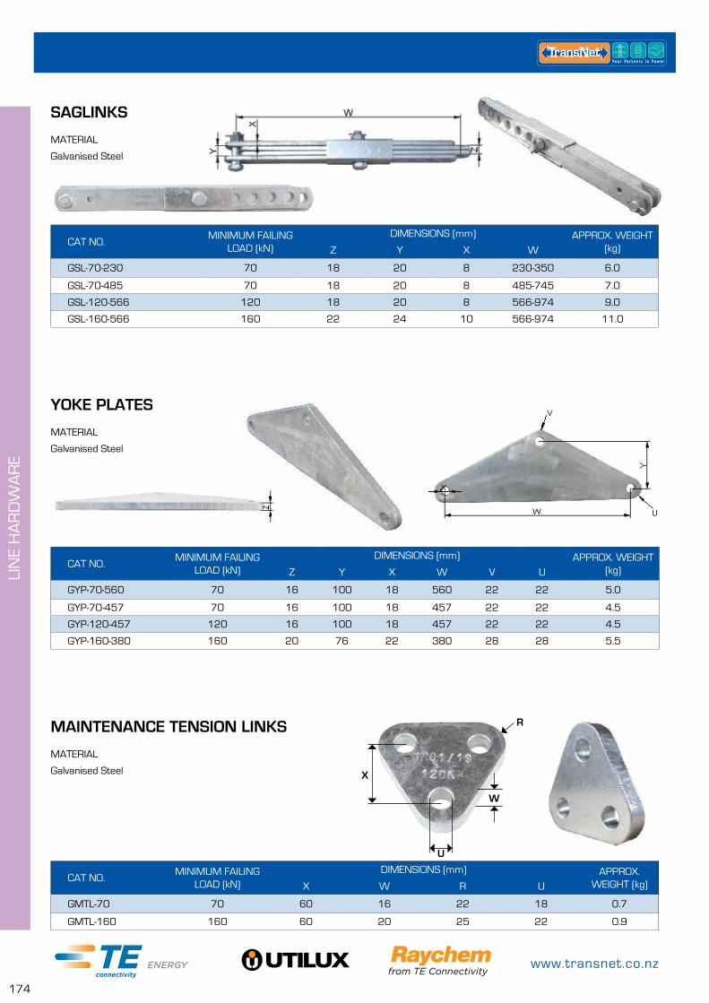
www.transnet.co.nz
174
LIN
E H
AR
DW
AR
E
CAT NO.MINIMUM FAILING
LOAD (kN)DIMENSIONS (mm) APPROX. WEIGHT
(kg)Z Y X W V U
GYP-70-560 70 16 100 18 560 22 22 5.0
GYP-70-457 70 16 100 18 457 22 22 4.5
GYP-120-457 120 16 100 18 457 22 22 4.5
GYP-160-380 160 20 76 22 380 28 28 5.5
CAT NO.MINIMUM FAILING
LOAD (kN)DIMENSIONS (mm) APPROX.
WEIGHT (kg)X W R U
GMTL-70 70 60 16 22 18 0.7
GMTL-160 160 60 20 25 22 0.9
YOKE PLATES
MAINTENANCE TENSION LINKS
MATERIAL
Galvanised Steel
MATERIAL
Galvanised Steel X
U
W
R
CAT NO.MINIMUM FAILING
LOAD (kN)DIMENSIONS (mm) APPROX. WEIGHT
(kg)Z Y X W
GSL-70-230 70 18 20 8 230-350 6.0
GSL-70-485 70 18 20 8 485-745 7.0
GSL-120-566 120 18 20 8 566-974 9.0
GSL-160-566 160 22 24 10 566-974 11.0
SAGLINKS
MATERIAL
Galvanised Steel
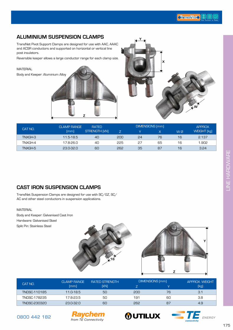
0800 442 182
175
LIN
E H
AR
DW
AR
E
CAT NO.CLAMP RANGE
(mm)RATED
STRENGTH (kN)DIMENSIONS (mm) APPROX.
WEIGHT (kg)Z Y X W Ø
TNXGH-3 11.5-18.5 40 200 24 76 16 2.137
TNXGH-4 17.8-26.0 40 225 27 65 16 1.902
TNXGH-5 23.0-32.0 60 262 35 87 16 3.24
CAT NO.CLAMP RANGE
(mm)RATED STRENGTH
(kN)DIMENSIONS (mm) APPROX. WEIGHT
(kg)Z Y
TNDSC-110185 11.0-18.5 50 200 76 3.1
TNDSC-178235 17.8-23.5 50 191 60 3.8
TNDSC-230320 23.0-32.0 60 262 87 4.9
ALUMINIUM SUSPENSION CLAMPS
CAST IRON SUSPENSION CLAMPS
TransNet Pivot Support Clamps are designed for use with AAC, AAAC and ACSR conductors and supported on horizontal or vertical line post insulators.
Reversible keeper allows a large conductor range for each clamp size.
MATERIAL
Body and Keeper: Aluminium Alloy
TransNet Suspension Clamps are designed for use with SC/GZ, SC/AC and other steel conductors in suspension applications.
MATERIAL
Body and Keeper: Galvanised Cast Iron
Hardware: Galvanised Steel
Split Pin: Stainless Steel
Z
W
16
Y
X
Z
Y

www.transnet.co.nz
176
LIN
E H
AR
DW
AR
E
STRAIN CLAMPS – ALUMINIUM & CAST IRONY
X
Z
W
TransNet Aluminium strain clamps are designed for use with AAC, AAAC or ACSR conductor. Cast Iron strain clamps are designed for use with SC/GZ, SC/AC and other steel conductors in suspension applications.
MATERIAL - Aluminium Clamps
Body and Keeper: Aluminium Alloy
Hardware: Galvanised Steel
Split Pin: Stainless Steel
MATERIAL - Cast Iron Clamps
Body and Keeper: Galvanised Cast Iron
Hardware: Galvanised Steel
Split Pin: Stainless Steel
CAT NO. TYPECLAMP RANGE (mm)
RATED STRENGTH
(kN)
DIMENSIONS (mm) U-BOLTS APPROX. WEIGHT
(kg)Z Y X W Ø NO.SIZE (mm)
TNATC-51114
ALUMINIUM
5.1-11.4 30 80 13 95 12 2 10 0.5
TNATC-80135 8.0-13.5 45 105 14 140 14 3 10 0.8
TNATC-89185 8.9-18.5 70 140 22 145 16 3 12 1.8
TNATC-50150 5.0-15.0 45 105 15 140 14 3 10 0.8
TNATC-121218 12.1-25.5 60 285 28 298 16 4 14 4.1
TNATC-180300 18.0-30.0 70 342 36 416 24 5 16 7.0
TNDTC-510
CAST IRON
5.0-10.0 20 120 18 150 16 2 12 1.3
TNDTC-1014 10.1-14.0 40 105 18 205 16 3 12 2.1
TNDTC-1418 14.1-18.0 70 160 22 310 18 4 16 4.6
TNDTC-1823 18.1-23.0 90 220 25 410 18 4 16 7.1
VIBRATION DAMPERS
TNSVD – For all AAC, AAAC, ACSR, Copper, SC/AC & SC/GZ conductor. Made from high impact, UV stable PVC rod.
Spiral Vibration Dampers were designed to reduce aeolian vibration in conductors, generated by the wind.
The gripping part of the SVD should be installed about 100–120mm away from other fittings. One SVD at each end of a span is adequate unless spans exceed 245m, where it is recommended two are installed at each end.
CAT NO.CONDUCTOR RANGE
(mm) ODCOLOUR
PACK QUANTITY
TNSVD0441 4.43 – 6.34 RED 25
TNSVD0635 6.35 – 8.29 BLUE 25
TNSVD0830 8.30 – 11.70 WHITE 25
TNSVD1173 11.71 – 14.30 YELLOW 25
TNSVD1432 14.32 – 19.30 GREEN 10
SPIRAL VIBRATION DAMPERS
Damping section Grippingsection
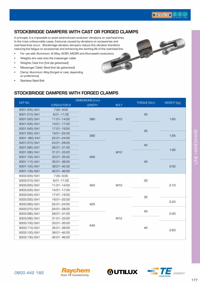
0800 442 182
177
LIN
E H
AR
DW
AR
E
STOCKBRIDGE DAMPERS WITH CAST OR FORGED CLAMPSIn principle, it is impossible to avoid wind-induced conductor vibrations on overhead lines. In the most unfavourable cases, fractures caused by vibrations on accessories and overhead lines occur. Stockbridge vibration dampers reduce this vibration therefore reducing the fatigue on accessories and enhancing the working life of the overhead line.
• For use with Aluminium, Al Alloy, ACSR, AACSR and Alumoweld conductors.
• Weights are cast onto the messenger cable
• Weights: Cast Iron (hot dip galvanised)
• Messenger Cable: Steel (hot dip galvanised)
• Clamp: Aluminium Alloy (forged or cast, depending on preference)
• Stainless Steel Bolt
CAT NO.DIMENSIONS (mm)
TORQUE (Nm) WEIGHT (kg)CONDUCTOR Ø LENGTH BOLT
9301.000/EA1 7.00–9.00
380 M10
30
1.60
9301.010/EA1 9.01–11.00
9301.020/EA1 11.01–14.50
9301.030/EA1 14.51–17.00
359301.040/EA1 17.01–19.50
9301.050/EA1 19.51–22.00390
M12
1.659301. 060/EA1 22.01–24.50
9301.070/EA1 24.51–28.00
400
40
1.909301.080/EA1 28.01–31.00
9301.090/EA1 31.01–33.00
45
9301.100/EA1 33.01–35.00
9301.110/EA1 35.01–38.00
2.009301.120/EA1 38.01–42.00
9301.130/EA1 42.01–46.00
9303.000/EA1 7.00–9.00
420 M10
30
2.10
9303.010/EA1 9.01–11.00
9303.020/EA1 11.01–14.50
9303.030/EA1 14.51–17.00
359303.040/EA1 17.01–19.50
9303.050/EA1 19.51–22.00
425
M12
2.209303.060/EA1 22.01–24.50
9303.070/EA1 24.51–28.0040
2.409303.080/EA1 28.01–31.00
440
9303.090/EA1 31.01–33.00
45
9303.100/EA1 33.01–35.00
2.609303.110/EA1 35.01–38.00
9303.120/EA1 38.01–42.00
9303.130/EA1 42.01–46.00
STOCKBRIDGE DAMPERS WITH FORGED CLAMPS
www.transnet.co.nz
178
LIN
E H
AR
DW
AR
E
CAT NO.DIMENSIONS (mm)
TORQUE (Nm) WEIGHT (kg)CONDUCTOR Ø LENGTH BOLT
9304.030/EA1 14.51–17.00450 M10
35
3.709304.040/EA1 17.01–19.50
9304.050/EA1 19.51–22.00455
M12
3.809304.060/EA1 22.01–24.50
9304.070/EA1 24.51–28.00
465
404.009304.080/EA1 28.01–31.00
9304.090/EA1 31.01–33.00
45
9304.100/EA1 33.01–35.00
4.109304.110/EA1 35.01–38.00
9304.120/EA1 38.01–42.00
9304.130/EA1 42.01–46.00
9306.070/EA1 24.51–28.00
520 M12
405.809306.080/EA1 28.01–31.00
9306.090/EA1 31.01–33.00
45
9306.100/EA1 33.01–35.00
6.009306.110/EA1 35.01–38.00
9306.120/EA1 38.01–42.00
9306.130/EA1 42.01–46.00
9308.070/EA1 24.51–28.00
570 M12
407.909308.080/EA1 28.01–31.00
9308.090/EA1 31.01–33.00
45
9308.100/EA1 33.01–35.00
8.109308.110/EA1 35.01–38.00
9308.120/EA1 38.01–42.00
9308.130/EA1 42.01–46.00
STOCKBRIDGE DAMPERS WITH FORGED CLAMPS CONT....
STOCKBRIDGE DAMPERS WITH CAST CLAMPS
CAT NO.DIMENSIONS (mm)
TORQUE (Nm) WEIGHT (kg)CONDUCTOR Ø LENGTH BOLT
9301.01/G/1 8.4–11.5
370M10
46
1.609301.02/G/1 11.6–14.0
9301.03/G/1 14.0–16.51.80
9301.04/G/1 16.6–19.0
9301.20/G/1 19.0–29.0 380 35 1.90
9303.01/G/1 8.4–11.5
410M10
46
2.109303.02/G/1 11.6–14.0
9303.03/G/1 14.0–16.52.30
9303.04/G/1 16.6–19.0
9303.06/G/1 19.0–29.0 420 35 2.40
9304.20/G/1 19.0–29.0450
M10 35 4.20
9304.10/G/1 28.5–38.0 M12 55 4.30
9306.03/G/1 19.0–29.0500
M10 356.10
9306.07/G/1 28.5–38.0 M12 55
9308.03/G/1 28.5–38.0 550 M12 55 8.00
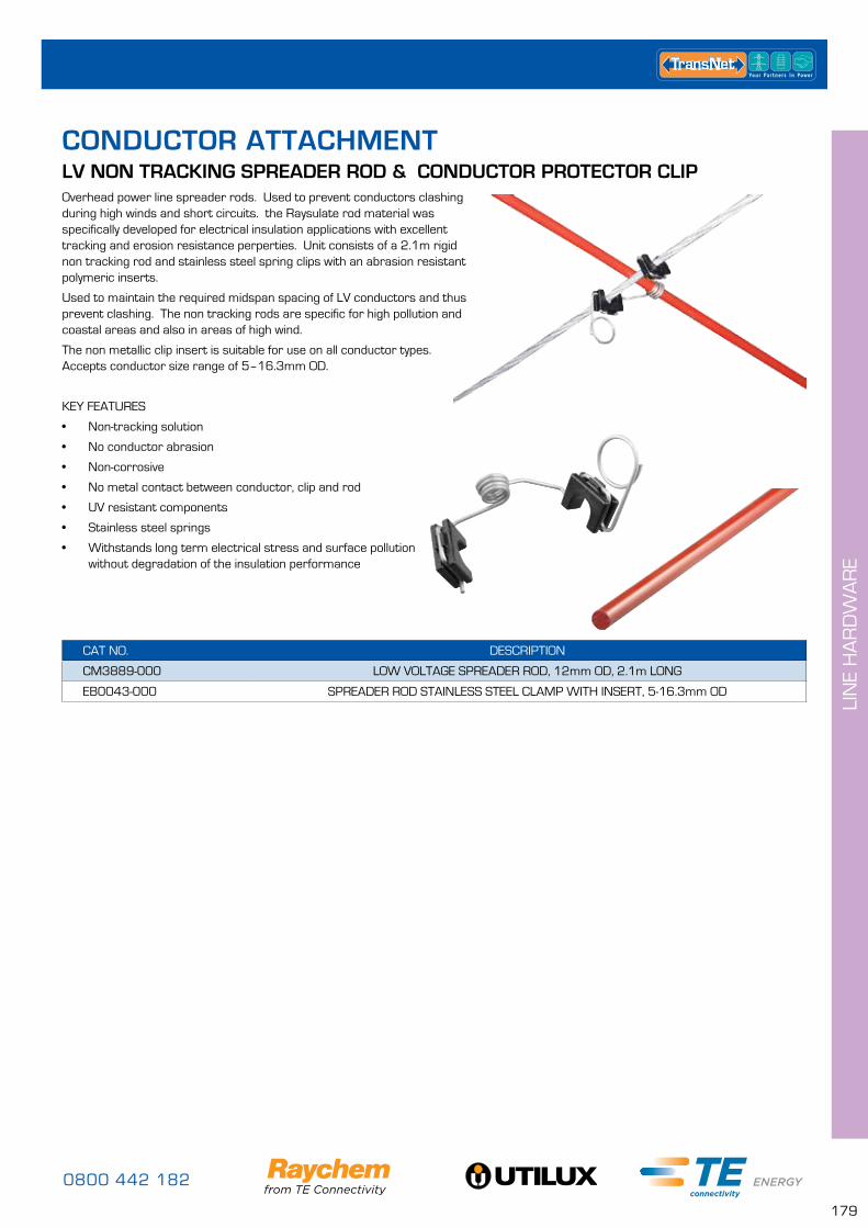
0800 442 182
179
LIN
E H
AR
DW
AR
E
CAT NO. DESCRIPTION
CM3889-000 LOW VOLTAGE SPREADER ROD, 12mm OD, 2.1m LONG
EB0043-000 SPREADER ROD STAINLESS STEEL CLAMP WITH INSERT, 5-16.3mm OD
LV NON TRACKING SPREADER ROD & CONDUCTOR PROTECTOR CLIPOverhead power line spreader rods. Used to prevent conductors clashing during high winds and short circuits. the Raysulate rod material was specifically developed for electrical insulation applications with excellent tracking and erosion resistance perperties. Unit consists of a 2.1m rigid non tracking rod and stainless steel spring clips with an abrasion resistant polymeric inserts.
Used to maintain the required midspan spacing of LV conductors and thus prevent clashing. The non tracking rods are specific for high pollution and coastal areas and also in areas of high wind.
The non metallic clip insert is suitable for use on all conductor types. Accepts conductor size range of 5–16.3mm OD.
KEY FEATURES
• Non-tracking solution
• No conductor abrasion
• Non-corrosive
• No metal contact between conductor, clip and rod
• UV resistant components
• Stainless steel springs
• Withstands long term electrical stress and surface pollution without degradation of the insulation performance
CONDUCTOR ATTACHMENT
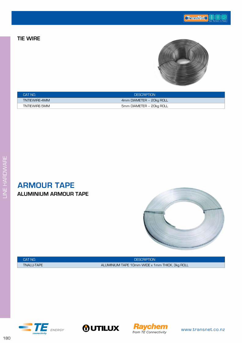
www.transnet.co.nz
180
LIN
E H
AR
DW
AR
E
ALUMINIUM ARMOUR TAPE
CAT NO. DESCRIPTION
TNALU-TAPE ALUMINIUM TAPE 10mm WIDE x 1mm THICK, 3kg ROLL
ARMOUR TAPE
TIE WIRE
CAT NO. DESCRIPTION
TNTIEWIRE-4MM 4mm DIAMETER – 20kg ROLL
TNTIEWIRE-5MM 5mm DIAMETER – 20kg ROLL
0800 442 182
181
INS
ULA
TOR
S
PORCELAIN INSULATORS PAGE
LV 182
MV Pin Type 186
MV Post Type 188
Stand Offs 189
Guy Strains 189
GLASS DISCS PAGE
Ball & Socket Glass Disc Type 190
String Electrical Ratings 194
POLYMER INSULATORS PAGE
Polymer Strains 198
Silicone Post Type 199
EVA Post Type 200
PIVOT SUPPORT CLAMPS PAGE
Aluminium Pivot Support Clamps 201
INSULATORS

www.transnet.co.nz
182
INS
ULA
TOR
S
GENERIC TECHNICAL DATA VALUE
CAT NO. 0-0361400-3
LINE VOLTAGE 650V
DRY FLASHOVER VOLTAGE 15kV
WET FLASHOVER VOLTAGE 8kV
BOLT SIZE M16
GROOVE 10mm
DESIGNED LOAD 7kN
COLOUR GREY
BOX QTY 140
LV SHACKLE PORCELAIN INSULATOR – 210
LV INSULATORS
CAT NO. KITSET DESCRIPTION
0-0361400-3 NO – INSULATOR ONLY 210 SHACKLE INSULATOR, PORCELAIN
210SHACKKITYES – INCLUDES GALV HARDWARE
210 LV SHACKLE INSULATOR KIT INCLUDES BOLTS & STRAPS
210USHACKCMPLT 210 LV SHACKLE INSULATOR KIT INCLUDES BOLTS & U-SHACKLE
210SHACKKIT
210USHACKKITCMPLT
103 SPIKE INSULATOR
GENERIC TECHNICAL DATA VALUE
CAT NO. 103
VOLTAGE 650V
DESIGN LOADING 4kN
HOLE/GROOVE 16mm HOLE
FIXING COACH SCREW
WEIGHT 325g
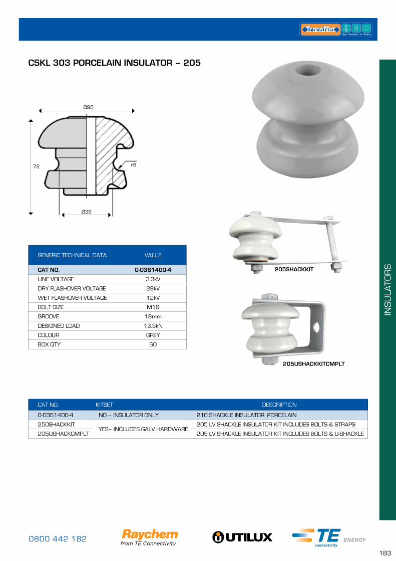
0800 442 182
183
INS
ULA
TOR
S
GENERIC TECHNICAL DATA VALUE
CAT NO. 0-0361400-4
LINE VOLTAGE 3.3kV
DRY FLASHOVER VOLTAGE 28kV
WET FLASHOVER VOLTAGE 12kV
BOLT SIZE M16
GROOVE 18mm
DESIGNED LOAD 13.5kN
COLOUR GREY
BOX QTY 60
CSKL 303 PORCELAIN INSULATOR – 205
Ø90
72
Ø38
r9
CAT NO. KITSET DESCRIPTION
0-0361400-4 NO – INSULATOR ONLY 210 SHACKLE INSULATOR, PORCELAIN
250SHACKKITYES– INCLUDES GALV HARDWARE
205 LV SHACKLE INSULATOR KIT INCLUDES BOLTS & STRAPS
205USHACKCMPLT 205 LV SHACKLE INSULATOR KIT INCLUDES BOLTS & U-SHACKLE
205SHACKKIT
205USHACKKITCMPLT
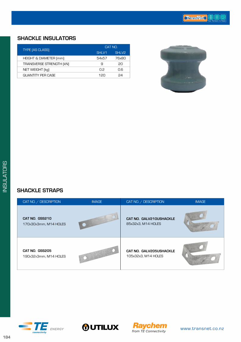
www.transnet.co.nz
184
INS
ULA
TOR
S
CAT NO. / DESCRIPTION IMAGE
CAT NO. GSS210
170x30x3mm, M14 HOLES
CAT NO. GSS205
190x32x3mm, M14 HOLES
CAT NO. / DESCRIPTION IMAGE
CAT NO. GALV210USHACKLE85x32x3, M14 HOLES
CAT NO. GALV205USHACKLE105x32x3, M14 HOLES
SHACKLE STRAPS
TYPE (AS CLASS)CAT NO.
SHLV1 SHLV2
HEIGHT & DIAMETER (mm) 54x57 76x80
TRANSVERSE STRENGTH (kN) 9 20
NET WEIGHT (kg) 0.2 0.6
QUANTITY PER CASE 120 24
SHACKLE INSULATORS
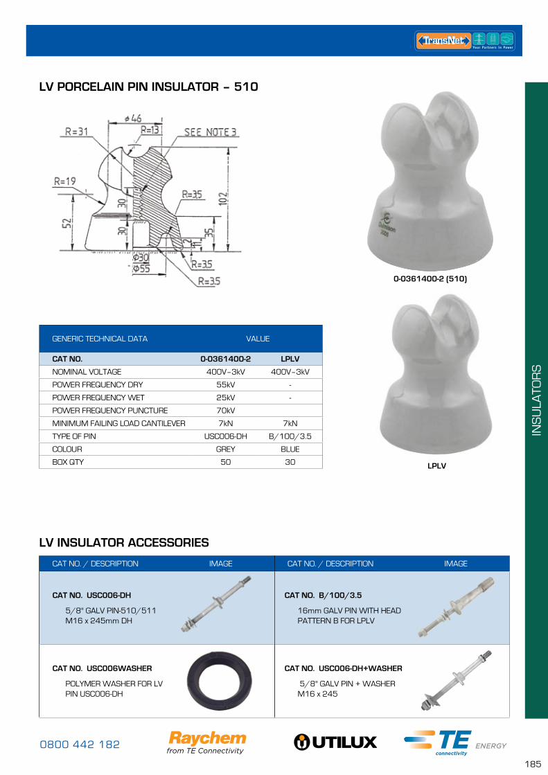
0800 442 182
185
INS
ULA
TOR
S
LV PORCELAIN PIN INSULATOR – 510
GENERIC TECHNICAL DATA VALUE
CAT NO. 0-0361400-2 LPLV
NOMINAL VOLTAGE 400V–3kV 400V–3kV
POWER FREQUENCY DRY 55kV -
POWER FREQUENCY WET 25kV -
POWER FREQUENCY PUNCTURE 70kV
MINIMUM FAILING LOAD CANTILEVER 7kN 7kN
TYPE OF PIN USC006-DH B/100/3.5
COLOUR GREY BLUE
BOX QTY 50 30
0-0361400-2 (510)
LPLV
LV INSULATOR ACCESSORIES
CAT NO. / DESCRIPTION IMAGE
CAT NO. B/100/3.5
16mm GALV PIN WITH HEAD PATTERN B FOR LPLV
CAT NO. USC006-DH+WASHER
5/8" GALV PIN + WASHER M16 x 245
CAT NO. / DESCRIPTION IMAGE
CAT NO. USC006-DH
5/8" GALV PIN-510/511 M16 x 245mm DH
CAT NO. USC006WASHER
POLYMER WASHER FOR LV PIN USC006-DH
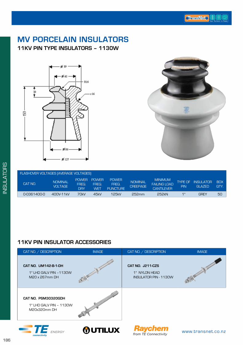
www.transnet.co.nz
186
INS
ULA
TOR
S
11KV PIN INSULATOR ACCESSORIES
CAT NO. / DESCRIPTION IMAGE
CAT NO. UM142-B-1-DH
1" LHD GALV PIN –1130W M20 x 267mm DH
CAT NO. PSM30320GDH
1" LHD GALV PIN – 1130W M20x320mm DH
CAT NO. / DESCRIPTION IMAGE
CAT NO. J211-CZS
1" NYLON HEAD INSULATOR PIN - 1130W
MV PORCELAIN INSULATORS
FLASHOVER VOLTAGES (AVERAGE VOLTAGES)
CAT NO. NOMINALVOLTAGE
POWERFREQ. DRY
POWERFREQ. WET
POWER FREQ.
PUNCTURE
NOMINAL CREEPAGE
MINIMUM FAILING LOAD CANTILEVER
TYPE OF PIN
INSULATOR GLAZED
BOXQTY.
0-0361400-0 400V-11kV 70kV 45kV 125kV 252mm 252kN 1" GREY 50
11KV PIN TYPE INSULATORS – 1130W
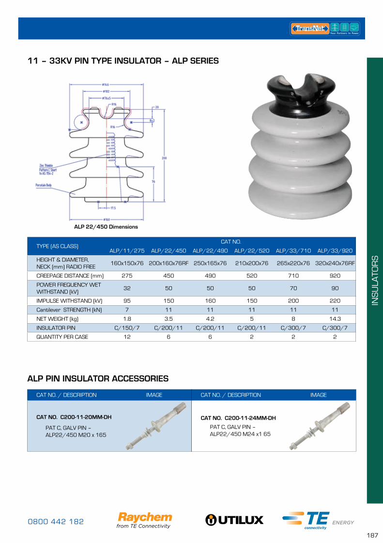
0800 442 182
187
INS
ULA
TOR
S
11 – 33KV PIN TYPE INSULATOR – ALP SERIES
ALP PIN INSULATOR ACCESSORIES
CAT NO. / DESCRIPTION IMAGE
CAT NO. C200-11-20MM-DH
PAT C, GALV PIN – ALP22/450 M20 x 165
CAT NO. / DESCRIPTION IMAGE
CAT NO. C200-11-24MM-DH
PAT C, GALV PIN – ALP22/450 M24 x1 65
TYPE (AS CLASS)CAT NO.
ALP/11/275 ALP/22/450 ALP/22/490 ALP/22/520 ALP/33/710 ALP/33/920
HEIGHT & DIAMETER, NECK (mm) RADIO FREE
160x150x76 200x160x76RF 250x165x76 210x200x76 265x220x76 320x240x76RF
CREEPAGE DISTANCE (mm) 275 450 490 520 710 920
POWER FREQUENCY WET WITHSTAND (kV)
32 50 50 50 70 90
IMPULSE WITHSTAND (kV) 95 150 160 150 200 220
Cantilever STRENGTH (kN) 7 11 11 11 11 11
NET WEIGHT (kg) 1.8 3.5 4.2 5 8 14.3
INSULATOR PIN C/150/7 C/200/11 C/200/11 C/200/11 C/300/7 C/300/7
QUANTITY PER CASE 12 6 6 2 2 2
ALP 22/450 Dimensions
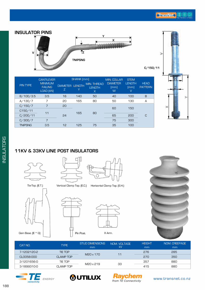
www.transnet.co.nz
188
INS
ULA
TOR
S
PIN TYPE
CANTILEVER MINIMUM
FAILING LOAD (kN)
SHANK (mm) MIN. COLLAR DIAMETER
(mm) W
STEM LENGTH
(mm) V
HEAD PATTERNDIAMETER
ZLENGTH
Y
MIN. THREAD LENGTH
X
B/100/3.5 3.5 16 140 50 40 100 B
A/130/7 7 20 165 80 50 130 A
C/150/7 7 20
165 80
60 150
C
C150/1111
24C/200/11 65 200
C/300/7 7 75 300
TNIPSNG 3.5 12 125 75 35 100
INSULATOR PINSY
X
WV Z
TNIPSNG
C/150/11
CAT NO. TYPESTUD DIMENSIONS
mmNOM. VOLTAGE
kVHEIGHT
mmNOM. CREEPAGE
mm
7-1202120-2 TIE TOPM20 x 170 11
276 285
CL0058-000 CLAMP TOP 270 350
3-1201656-0 TIE TOPM20 x 219 33
357 880
3-1899310-0 CLAMP TOP 415 880
11KV & 33KV LINE POST INSULATORS
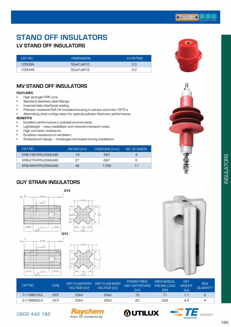
0800 442 182
189
INS
ULA
TOR
S
STAND OFF INSULATORSLV STAND OFF INSULATORS
MV STAND OFF INSULATORS
CAT NO. DIMENSIONS kV RATING
1050GN 50x41xM10 3.3
1050HN 50x41xM12 3.3
CAT NO. RATING (KV) CREEPAGE (mm) NO. OF SHEDS
EPBI-19R-PPG-25KN-M0 19 497 4
EPBI-27R-PPG-25KN-M0 27 687 6
EPBI-46R-PPG-25KN-M0 46 1169 11
FEATURES: • High strength FRP core• Standard stainless steel fittings• Impenetrable interfacial sealing• Pollution resistant EVA HV insulationhousing in service since the 1970’s. • Alternating shed configuration for optimal pollution flashover performanceBENEFITS: • Excellent performance in polluted environments • Lightweight – easy installation and reduced transport costs• High corrosion resistance • Excellent resistance to vandalism • Shatterproof design – breakages eliminated during installation.
CAT NO. TYPEDRY FLASHOVER
VOLTAGE (kV)WET FLASHOVER
VOLTAGE (kV)
POWER FREQ. WET WITHSTAND
(kV)
MECHANICAL FAILING LOAD
(kN)
NET WEIGHT
(kg)
BOX QUANTITY
7-1198679-2 GY2 55kV 25kV 15 71 1.1 6
3-1198665-3 GY3 55kV 25kV 20 222 4.3 4
GUY STRAIN INSULATORS

www.transnet.co.nz
190
INS
ULA
TOR
S
SEDIVER BALL & SOCKET TYPE, STANDARD PROFILE - 70KN / 100KN
CAT NO. F70/127 F70/146 F100/127 F100/146
IEC CLASS (1) U70BS U70BL U100BS U100BL
MECHANICAL CHARACTERISTICS
MIN MECHANICAL FAILING LOAD kN 70 70 100 100
DIMENSIONS
DIAMETER (D) mm 255 255 255 255
SPACING (S) mm 127 146 127 146
CREEPAGE DISTANCE mm 320 320 320 320
METAL FITTING SIZE (2) 16A 16A 16A 16A
ELECTRICAL CHARACTERISTICS (3)
POWER FREQ. WITHSTAND VOLTAGE
- DRY ONE MINUTE kV 70 70 70 70
- WET ONE MINUTE kV 40 40 40 40
DRY LIGHTNING IMPULSE WITHSTAND VOLTAGE kV 100 100 100 100
PUNCTURE WITHSTAND VOLTAGE kV 130 130 130 130
TOUGHENED GLASS SUSPENSION INSULATORS
(1) in accordance with IEC publication 60305(2) in accordance with IEC publication 60120(3) in accordance with IEC publication 60383-1
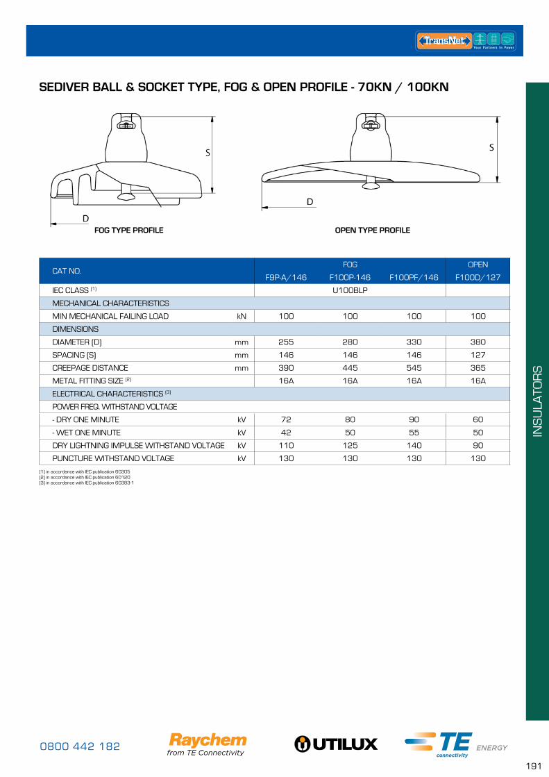
0800 442 182
191
INS
ULA
TOR
S
SEDIVER BALL & SOCKET TYPE, FOG & OPEN PROFILE - 70KN / 100KN
CAT NO.FOG OPEN
F9P-A/146 F100P-146 F100PF/146 F100D/127
IEC CLASS (1) U100BLP
MECHANICAL CHARACTERISTICS
MIN MECHANICAL FAILING LOAD kN 100 100 100 100
DIMENSIONS
DIAMETER (D) mm 255 280 330 380
SPACING (S) mm 146 146 146 127
CREEPAGE DISTANCE mm 390 445 545 365
METAL FITTING SIZE (2) 16A 16A 16A 16A
ELECTRICAL CHARACTERISTICS (3)
POWER FREQ. WITHSTAND VOLTAGE
- DRY ONE MINUTE kV 72 80 90 60
- WET ONE MINUTE kV 42 50 55 50
DRY LIGHTNING IMPULSE WITHSTAND VOLTAGE kV 110 125 140 90
PUNCTURE WITHSTAND VOLTAGE kV 130 130 130 130
(1) in accordance with IEC publication 60305(2) in accordance with IEC publication 60120(3) in accordance with IEC publication 60383-1
FOG TYPE PROFILE OPEN TYPE PROFILE
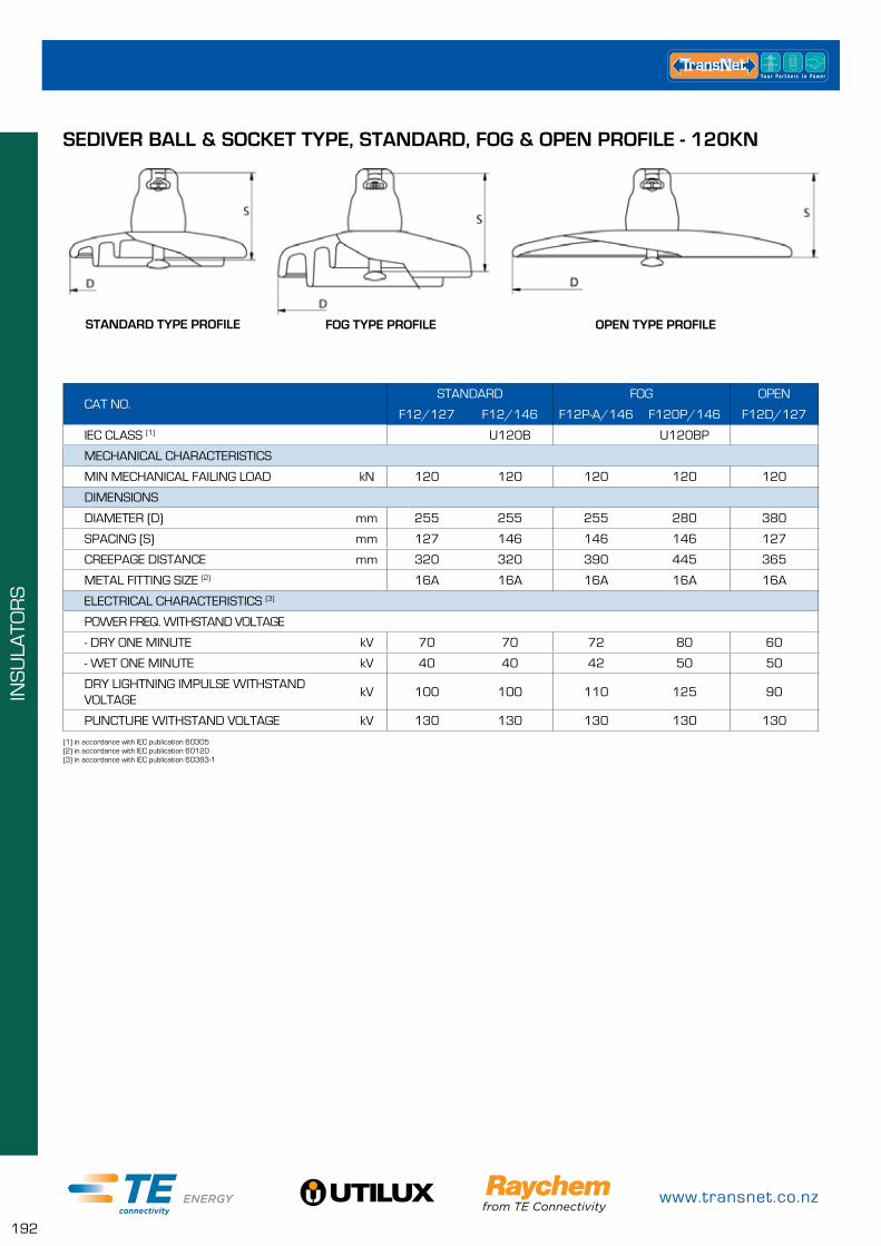
www.transnet.co.nz
192
INS
ULA
TOR
S
SEDIVER BALL & SOCKET TYPE, STANDARD, FOG & OPEN PROFILE - 120KN
CAT NO.STANDARD FOG OPEN
F12/127 F12/146 F12P-A/146 F120P/146 F12D/127
IEC CLASS (1) U120B U120BP
MECHANICAL CHARACTERISTICS
MIN MECHANICAL FAILING LOAD kN 120 120 120 120 120
DIMENSIONS
DIAMETER (D) mm 255 255 255 280 380
SPACING (S) mm 127 146 146 146 127
CREEPAGE DISTANCE mm 320 320 390 445 365
METAL FITTING SIZE (2) 16A 16A 16A 16A 16A
ELECTRICAL CHARACTERISTICS (3)
POWER FREQ. WITHSTAND VOLTAGE
- DRY ONE MINUTE kV 70 70 72 80 60
- WET ONE MINUTE kV 40 40 42 50 50
DRY LIGHTNING IMPULSE WITHSTAND VOLTAGE
kV 100 100 110 125 90
PUNCTURE WITHSTAND VOLTAGE kV 130 130 130 130 130
(1) in accordance with IEC publication 60305(2) in accordance with IEC publication 60120(3) in accordance with IEC publication 60383-1
FOG TYPE PROFILE OPEN TYPE PROFILESTANDARD TYPE PROFILE
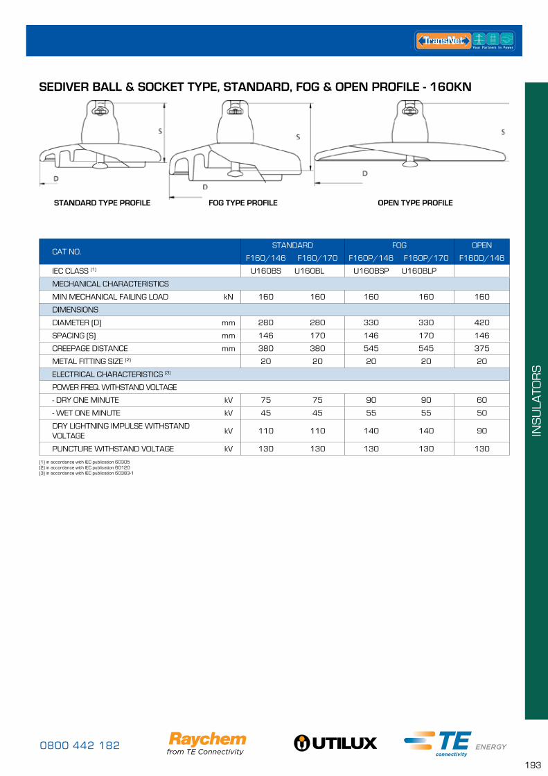
0800 442 182
193
INS
ULA
TOR
S
SEDIVER BALL & SOCKET TYPE, STANDARD, FOG & OPEN PROFILE - 160KN
CAT NO.STANDARD FOG OPEN
F160/146 F160/170 F160P/146 F160P/170 F160D/146
IEC CLASS (1) U160BS U160BL U160BSP U160BLP
MECHANICAL CHARACTERISTICS
MIN MECHANICAL FAILING LOAD kN 160 160 160 160 160
DIMENSIONS
DIAMETER (D) mm 280 280 330 330 420
SPACING (S) mm 146 170 146 170 146
CREEPAGE DISTANCE mm 380 380 545 545 375
METAL FITTING SIZE (2) 20 20 20 20 20
ELECTRICAL CHARACTERISTICS (3)
POWER FREQ. WITHSTAND VOLTAGE
- DRY ONE MINUTE kV 75 75 90 90 60
- WET ONE MINUTE kV 45 45 55 55 50
DRY LIGHTNING IMPULSE WITHSTAND VOLTAGE
kV 110 110 140 140 90
PUNCTURE WITHSTAND VOLTAGE kV 130 130 130 130 130
(1) in accordance with IEC publication 60305(2) in accordance with IEC publication 60120(3) in accordance with IEC publication 60383-1
FOG TYPE PROFILE OPEN TYPE PROFILESTANDARD TYPE PROFILE
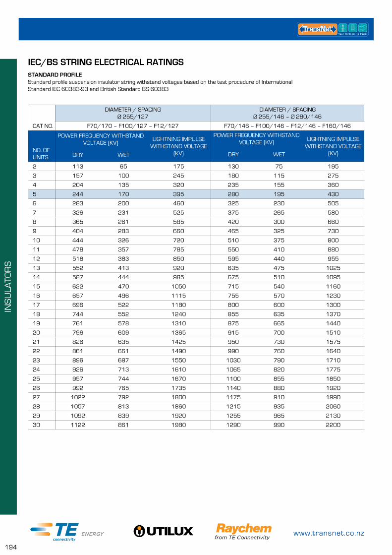
www.transnet.co.nz
194
INS
ULA
TOR
S
IEC/BS STRING ELECTRICAL RATINGSSTANDARD PROFILEStandard profile suspension insulator string withstand voltages based on the test procedure of International Standard IEC 60383-93 and British Standard BS 60383
CAT NO.
DIAMETER / SPACING Ø 255/127
DIAMETER / SPACING Ø 255/146 – Ø 280/146
F70/170 – F100/127 – F12/127 F70/146 – F100/146 – F12/146 – F160/146
NO. OF UNITS
POWER FREQUENCY WITHSTAND VOLTAGE (KV)
LIGHTNING IMPULSE WITHSTAND VOLTAGE
(KV)
POWER FREQUENCY WITHSTAND VOLTAGE (KV) LIGHTNING IMPULSE
WITHSTAND VOLTAGE (KV)DRY WETDRY WET
2 113 65 175 130 75 195
3 157 100 245 180 115 275
4 204 135 320 235 155 360
5 244 170 395 280 195 430
6 283 200 460 325 230 505
7 326 231 525 375 265 580
8 365 261 585 420 300 660
9 404 283 660 465 325 730
10 444 326 720 510 375 800
11 478 357 785 550 410 880
12 518 383 850 595 440 955
13 552 413 920 635 475 1025
14 587 444 985 675 510 1095
15 622 470 1050 715 540 1160
16 657 496 1115 755 570 1230
17 696 522 1180 800 600 1300
18 744 552 1240 855 635 1370
19 761 578 1310 875 665 1440
20 796 609 1365 915 700 1510
21 826 635 1425 950 730 1575
22 861 661 1490 990 760 1640
23 896 687 1550 1030 790 1710
24 926 713 1610 1065 820 1775
25 957 744 1670 1100 855 1850
26 992 765 1735 1140 880 1920
27 1022 792 1800 1175 910 1990
28 1057 813 1860 1215 935 2060
29 1092 839 1920 1255 965 2130
30 1122 861 1980 1290 990 2200
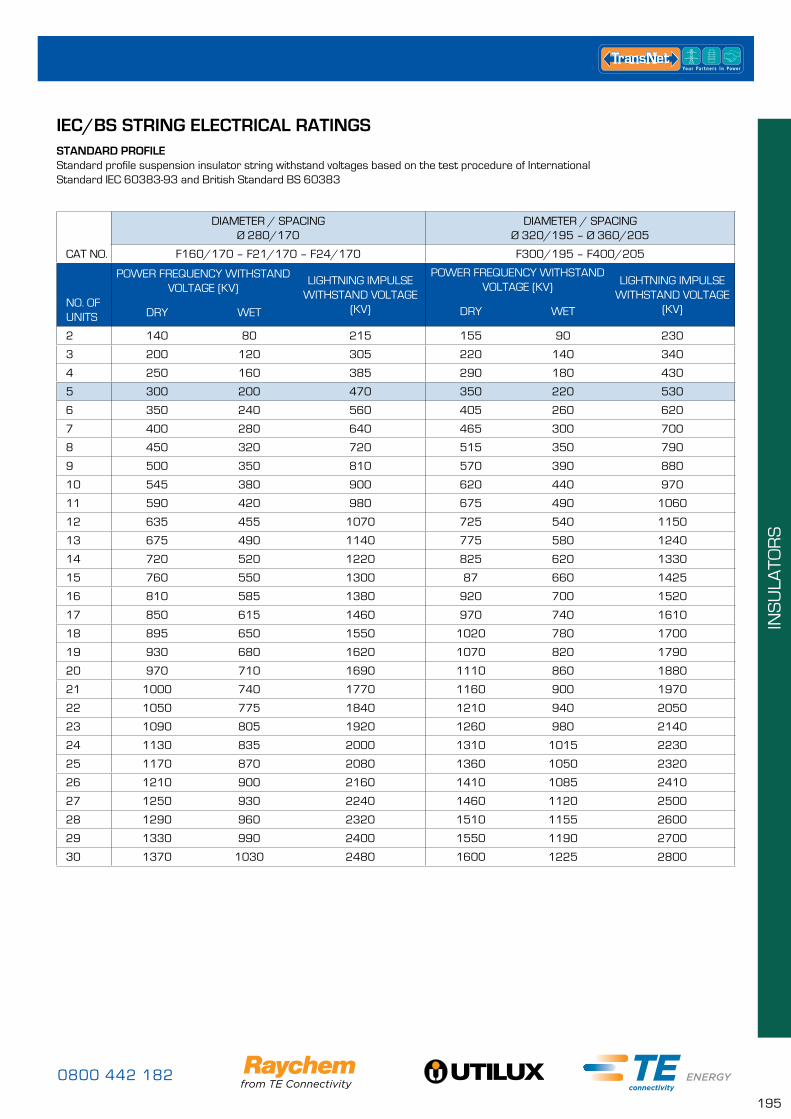
0800 442 182
195
INS
ULA
TOR
S
IEC/BS STRING ELECTRICAL RATINGSSTANDARD PROFILEStandard profile suspension insulator string withstand voltages based on the test procedure of International Standard IEC 60383-93 and British Standard BS 60383
CAT NO.
DIAMETER / SPACING Ø 280/170
DIAMETER / SPACING Ø 320/195 – Ø 360/205
F160/170 – F21/170 – F24/170 F300/195 – F400/205
NO. OF UNITS
POWER FREQUENCY WITHSTAND VOLTAGE (KV)
LIGHTNING IMPULSE WITHSTAND VOLTAGE
(KV)
POWER FREQUENCY WITHSTAND VOLTAGE (KV) LIGHTNING IMPULSE
WITHSTAND VOLTAGE (KV)DRY WETDRY WET
2 140 80 215 155 90 230
3 200 120 305 220 140 340
4 250 160 385 290 180 430
5 300 200 470 350 220 530
6 350 240 560 405 260 620
7 400 280 640 465 300 700
8 450 320 720 515 350 790
9 500 350 810 570 390 880
10 545 380 900 620 440 970
11 590 420 980 675 490 1060
12 635 455 1070 725 540 1150
13 675 490 1140 775 580 1240
14 720 520 1220 825 620 1330
15 760 550 1300 87 660 1425
16 810 585 1380 920 700 1520
17 850 615 1460 970 740 1610
18 895 650 1550 1020 780 1700
19 930 680 1620 1070 820 1790
20 970 710 1690 1110 860 1880
21 1000 740 1770 1160 900 1970
22 1050 775 1840 1210 940 2050
23 1090 805 1920 1260 980 2140
24 1130 835 2000 1310 1015 2230
25 1170 870 2080 1360 1050 2320
26 1210 900 2160 1410 1085 2410
27 1250 930 2240 1460 1120 2500
28 1290 960 2320 1510 1155 2600
29 1330 990 2400 1550 1190 2700
30 1370 1030 2480 1600 1225 2800
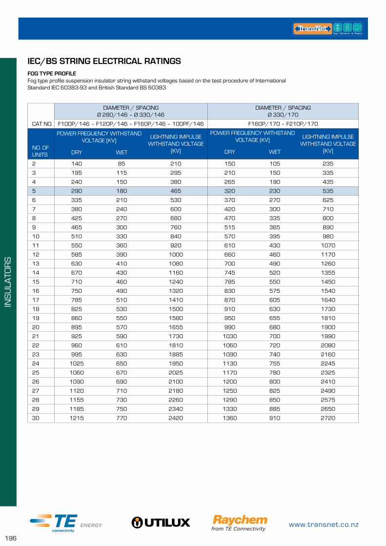
www.transnet.co.nz
196
INS
ULA
TOR
S
IEC/BS STRING ELECTRICAL RATINGSFOG TYPE PROFILEFog type profile suspension insulator string withstand voltages based on the test procedure of International Standard IEC 60383-93 and British Standard BS 60383
CAT NO.
DIAMETER / SPACING Ø 280/146 – Ø 330/146
DIAMETER / SPACING Ø 330/170
F100P/146 – F120P/146 – F160P/146 – 100PF/146 F160P/170 – F210P/170
NO. OF UNITS
POWER FREQUENCY WITHSTAND VOLTAGE (KV)
LIGHTNING IMPULSE WITHSTAND VOLTAGE
(KV)
POWER FREQUENCY WITHSTAND VOLTAGE (KV) LIGHTNING IMPULSE
WITHSTAND VOLTAGE (KV)DRY WETDRY WET
2 140 85 210 150 105 235
3 195 115 295 210 150 335
4 240 150 380 265 190 435
5 290 180 465 320 230 535
6 335 210 530 370 270 625
7 380 240 600 420 300 710
8 425 270 680 470 335 800
9 465 300 760 515 365 890
10 510 330 840 570 395 980
11 550 360 920 610 430 1070
12 585 390 1000 660 460 1170
13 630 410 1080 700 490 1260
14 670 430 1160 745 520 1355
15 710 460 1240 785 550 1450
16 750 490 1320 830 575 1540
17 785 510 1410 870 605 1640
18 825 530 1500 910 630 1730
19 860 550 1580 950 655 1810
20 895 570 1655 990 680 1900
21 925 590 1730 1030 700 1990
22 960 610 1810 1060 720 2080
23 995 630 1885 1090 740 2160
24 1025 650 1950 1130 755 2245
25 1060 670 2025 1170 780 2325
26 1090 690 2100 1200 800 2410
27 1120 710 2180 1250 825 2490
28 1155 730 2260 1290 850 2575
29 1185 750 2340 1330 885 2650
30 1215 770 2420 1360 910 2720
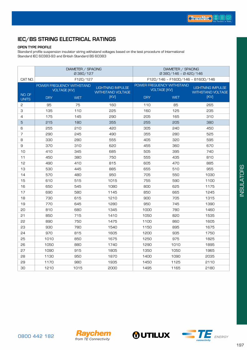
0800 442 182
197
INS
ULA
TOR
S
IEC/BS STRING ELECTRICAL RATINGSOPEN TYPE PROFILEStandard profile suspension insulator string withstand voltages based on the test procedure of International Standard IEC 60383-93 and British Standard BS 60383
CAT NO.
DIAMETER / SPACING Ø 380/127
DIAMETER / SPACING Ø 380/146 – Ø 420/146
F12D/127 F12D/146 – F160D/146 – B160D/146
NO. OF UNITS
POWER FREQUENCY WITHSTAND VOLTAGE (KV)
LIGHTNING IMPULSE WITHSTAND VOLTAGE
(KV)
POWER FREQUENCY WITHSTAND VOLTAGE (KV) LIGHTNING IMPULSE
WITHSTAND VOLTAGE (KV)DRY WETDRY WET
2 95 75 160 110 85 265
3 135 110 225 160 125 235
4 175 145 290 205 165 310
5 215 180 355 255 205 380
6 255 210 420 305 240 450
7 290 245 490 355 280 525
8 330 280 555 405 320 595
9 370 310 620 455 360 670
10 410 345 685 505 395 740
11 450 380 750 555 435 810
12 490 410 815 605 470 885
13 530 445 885 655 510 955
14 570 480 950 705 550 1030
15 610 515 1015 755 590 1100
16 650 545 1080 800 625 1175
17 690 580 1145 850 665 1245
18 730 615 1210 900 705 1315
19 770 645 1280 950 745 1390
20 810 680 1345 1000 780 1460
21 850 715 1410 1050 820 1535
22 890 750 1475 1100 860 1605
23 930 780 1540 1150 895 1675
24 970 815 1605 1200 935 1750
25 1010 850 1675 1250 975 1825
26 1050 880 1740 1290 1010 1895
27 1090 915 1805 1350 1050 1965
28 1130 950 1870 1400 1090 2035
29 1170 980 1935 1450 1125 2110
30 1210 1015 2000 1495 1165 2180
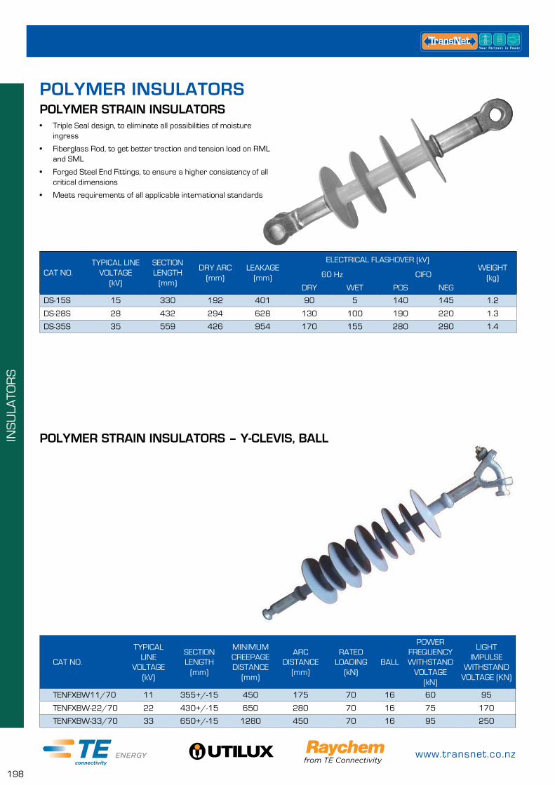
www.transnet.co.nz
198
INS
ULA
TOR
S
• Triple Seal design, to eliminate all possibilities of moisture ingress
• Fiberglass Rod, to get better traction and tension load on RML and SML
• Forged Steel End Fittings, to ensure a higher consistency of all critical dimensions
• Meets requirements of all applicable international standards
POLYMER STRAIN INSULATORS
CAT NO.TYPICAL LINE
VOLTAGE (kV)
SECTION LENGTH
(mm)
DRY ARC (mm)
LEAKAGE (mm)
ELECTRICAL FLASHOVER (kV)WEIGHT
(kg)60 Hz CIFO
DRY WET POS NEG
DS-15S 15 330 192 401 90 5 140 145 1.2
DS-28S 28 432 294 628 130 100 190 220 1.3
DS-35S 35 559 426 954 170 155 280 290 1.4
POLYMER INSULATORS
POLYMER STRAIN INSULATORS – Y-CLEVIS, BALL
CAT NO.
TYPICAL LINE
VOLTAGE (kV)
SECTION LENGTH
(mm)
MINIMUM CREEPAGE DISTANCE
(mm)
ARC DISTANCE
(mm)
RATED LOADING
(kN)BALL
POWER FREQUENCY WITHSTAND
VOLTAGE (kN)
LIGHT IMPULSE
WITHSTAND VOLTAGE (KN)
TENFXBW11/70 11 355+/-15 450 175 70 16 60 95
TENFXBW-22/70 22 430+/-15 650 280 70 16 75 170
TENFXBW-33/70 33 650+/-15 1280 450 70 16 95 250
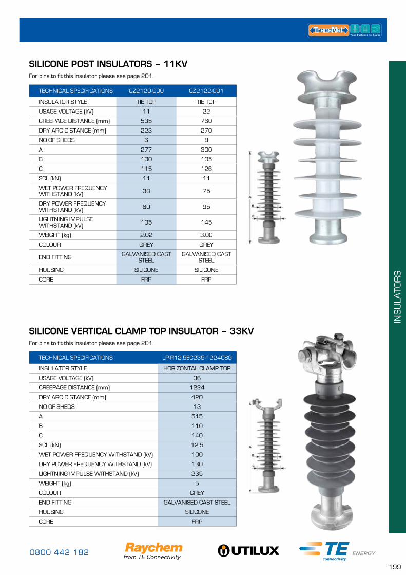
0800 442 182
199
INS
ULA
TOR
S
SILICONE POST INSULATORS – 11KV
SILICONE VERTICAL CLAMP TOP INSULATOR – 33KV
TECHNICAL SPECIFICATIONS LP-R12.5EC235-1224CSG
INSULATOR STYLE HORIZONTAL CLAMP TOP
USAGE VOLTAGE (kV) 36
CREEPAGE DISTANCE (mm) 1224
DRY ARC DISTANCE (mm) 420
NO OF SHEDS 13
A 515
B 110
C 140
SCL (kN) 12.5
WET POWER FREQUENCY WITHSTAND (kV) 100
DRY POWER FREQUENCY WITHSTAND (kV) 130
LIGHTNING IMPULSE WITHSTAND (kV) 235
WEIGHT (kg) 5
COLOUR GREY
END FITTING GALVANISED CAST STEEL
HOUSING SILICONE
CORE FRP
TECHNICAL SPECIFICATIONS CZ2120-000 CZ2122-001
INSULATOR STYLE TIE TOP TIE TOP
USAGE VOLTAGE (kV) 11 22
CREEPAGE DISTANCE (mm) 535 760
DRY ARC DISTANCE (mm) 223 270
NO OF SHEDS 6 8
A 277 300
B 100 105
C 115 126
SCL (kN) 11 11
WET POWER FREQUENCY WITHSTAND (kV) 38 75
DRY POWER FREQUENCY WITHSTAND (kV) 60 95
LIGHTNING IMPULSE WITHSTAND (kV) 105 145
WEIGHT (kg) 2.02 3.00
COLOUR GREY GREY
END FITTING GALVANISED CAST STEEL
GALVANISED CAST STEEL
HOUSING SILICONE SILICONE
CORE FRP FRP
For pins to fit this insulator please see page 201.
For pins to fit this insulator please see page 201.
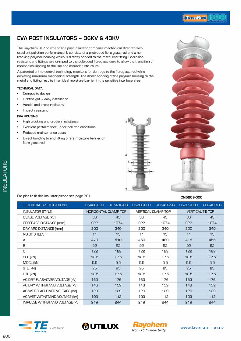
www.transnet.co.nz
200
INS
ULA
TOR
S
TECHNICAL SPECIFICATIONS C5420-000 RLP-43R-HG C5208-000 RLP-43R-VG C5209-000 RLP-43R-FG
INSULATOR STYLE HORIZONTAL CLAMP TOP VERTICAL CLAMP TOP VERTICAL TIE TOP
USAGE VOLTAGE (kV) 36 43 36 43 36 43
CREEPAGE DISTANCE (mm) 922 1074 922 1074 922 1074
DRY ARC DISTANCE (mm) 300 340 300 340 300 340
NO OF SHEDS 11 13 11 13 11 13
A 470 510 450 489 415 455
B 92 92 92 92 92 92
C 122 122 122 122 122 122
SCL (kN) 12.5 12.5 12.5 12.5 12.5 12.5
MDCL (kN) 5.5 5.5 5.5 5.5 5.5 5.5
STL (kN) 25 25 25 25 25 25
RTL (kN) 12.5 12.5 12.5 12.5 12.5 12.5
AC DRY FLASHOVER VOLTAGE (kV) 163 176 163 176 163 176
AC DRY WITHSTAND VOLTAGE (kV) 146 159 146 159 146 159
AC WET FLASHOVER VOLTAGE (kV) 120 129 120 129 120 129
AC WET WITHSTAND VOLTAGE (kV) 103 112 103 112 103 112
IMPULSE WITHSTAND VOLTAGE (kV) 219 244 219 244 219 244
EVA POST INSULATORS – 36KV & 43KV
The Raychem RLP polymeric line post insulator combines mechanical strength with excellent pollution performance. It consists of a protruded fibre glass rod and a non-tracking polymer housing which is directly bonded to the metal end fitting. Corrosion resistant end fittings are crimped to the pultruded fibreglass core to allow the transition of mechanical loading to the line and mounting structure.
A patented crimp control technology monitors for damage to the fibreglass rod while achieving maximum mechanical strength. The direct bonding of the polymer housing to the metal end fitting results in an ideal moisture barrier in the sensitive interface area.
TECHNICAL DATA
• Composite design
• Lightweight – easy installation
• Vandal and break resistant
• Impact resistant
EVA HOUSING
• High tracking and erosion resistance
• Excellent performance under polluted conditions
• Reduced maintenance costs
• Direct bonding to end fitting offers moisture barrier on fibre glass rod.
CN5209-000For pins to fit this insulator please see page 201.

0800 442 182
201
INS
ULA
TOR
S
CAT NO. DESCRIPTION
3-1198345-6 AL C/TOP CLAMP 7 - 32mm OD
CN6147-000 STUD M20 x 218mm (X-ARM MOUNT)
CN6148-000 STUD M20 x 90mm (CHANNEL MOUNT)
EVA & SILIONE POST INSULATOR ACCESSORIES
CN6147-000
CN6148-000
3-1198345-6
CAT NO. TYPECLAMP
RANGE (mm)RATED
STRENGTH (kN)DIMENSIONS (mm) APPROX.
WEIGHT (kg)Z Y BOLT SIZE
TNTSC-0614
ALUMINIUM
6-14
12 133 99M12
0.5
TNTSC-0921 9-21 0.5
TNTSC-1327 13-27 0.6
TNTSC-2538 25-38 0.6
3-1198345-6 7-32 12 133 98.5 0.5
TNDTSC-0614
CAST IRON
6-14
12 133 98.5 M12
1.1
TNDTSC-1327 13-27 1.2
TNDTSC-2538 25-38 1.3
ALUMINIUM PIVOT SUPPORT CLAMPSAluminium Pivot Support Clamps are designed for use with AAC, AAAC and ACSR conductors and supported on horizontal or vertical line post insulators and Cast Iron Pivot Support Clamps are designed for use with SC/GZ, SC/AC and other steel conductors in suspension.
Reversible keeper allows a large conductor range for each clamp size.
PIVOT SUPPORT CLAMPS
www.transnet.co.nz
202
INS
ULA
TOR
S
RAYCHEM HIGH VOLTAGE TEST LAB
0800 442 182
203
CIR
CU
IT P
RO
TEC
TIO
N &
FU
SE
LIN
KS
CIRCUIT PROTECTION & FUSE LINKSFUSE LINKS PAGE
Staggered Tag 204
Offset Tag 204
Central Tag 206
J Type 207
Cylindrical Type 207
NH Din Type 208
Cooper Bussmann Oil Fuse Links 12kV 210
AB Chance Type K & Type T DDO Fuse Links 211
LV OVERHEAD FUSE SWITCHES PAGE
K223 212
TNNHP100 Fuse Carrier 212
K491 213
K291 & K292 213
Brackets for K491, K291 & K292 213
Krone KGH160 214
Krone KGH250 214
Krone KGH400 215
630A LV Isolating Link - Fused/Unfused 215
Fuse Pulling Tools 216
LV UNDERGROUND FUSE SWITCHES PAGE
65U 216
K221 216
K199 216
MV OVERHEAD DDO'S (CUT OUTS) PAGE
DDO Fuse Units 218
SURGE ARRESTORS PAGE
Surge Arrestor Eye Bolt Connector 218
CLASS 1 – BOW DAH Series 219
CLASS 1 – EVA HDA-MA Series 219
CLASS 2 – Station Class 220
FAULT PASSAGE INDICATORS PAGE
Overhead – FLITE110SA & FLITE116SA 221
Underground – FLAIR213 & FLAIR279 221
Accessories 222
MV SWITCHGEAR PAGE
ABS Switchgear 222
G&W Switchgear 223
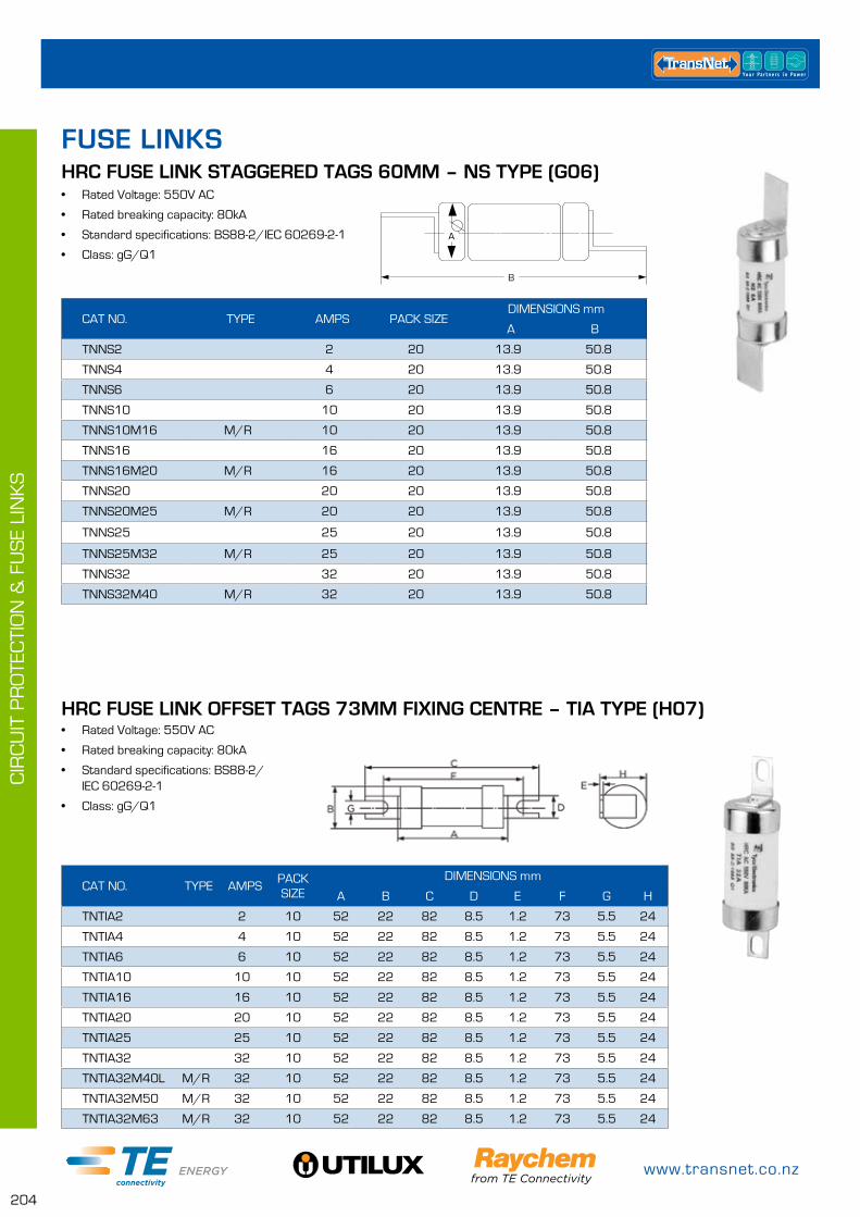
www.transnet.co.nz
204
CIR
CU
IT P
RO
TEC
TIO
N &
FU
SE
LIN
KS
• Rated Voltage: 550V AC
• Rated breaking capacity: 80kA
• Standard specifications: BS88-2/IEC 60269-2-1
• Class: gG/Q1
• Rated Voltage: 550V AC
• Rated breaking capacity: 80kA
• Standard specifications: BS88-2/ IEC 60269-2-1
• Class: gG/Q1
HRC FUSE LINK STAGGERED TAGS 60MM – NS TYPE (G06)
CAT NO. TYPE AMPS PACK SIZEDIMENSIONS mm
A B
TNNS2 2 20 13.9 50.8
TNNS4 4 20 13.9 50.8
TNNS6 6 20 13.9 50.8
TNNS10 10 20 13.9 50.8
TNNS10M16 M/R 10 20 13.9 50.8
TNNS16 16 20 13.9 50.8
TNNS16M20 M/R 16 20 13.9 50.8
TNNS20 20 20 13.9 50.8
TNNS20M25 M/R 20 20 13.9 50.8
TNNS25 25 20 13.9 50.8
TNNS25M32 M/R 25 20 13.9 50.8
TNNS32 32 20 13.9 50.8
TNNS32M40 M/R 32 20 13.9 50.8
A
B
HRC FUSE LINK OFFSET TAGS 73MM FIXING CENTRE – TIA TYPE (H07)
CAT NO. TYPE AMPSPACK SIZE
DIMENSIONS mm
A B C D E F G H
TNTIA2 2 10 52 22 82 8.5 1.2 73 5.5 24
TNTIA4 4 10 52 22 82 8.5 1.2 73 5.5 24
TNTIA6 6 10 52 22 82 8.5 1.2 73 5.5 24
TNTIA10 10 10 52 22 82 8.5 1.2 73 5.5 24
TNTIA16 16 10 52 22 82 8.5 1.2 73 5.5 24
TNTIA20 20 10 52 22 82 8.5 1.2 73 5.5 24
TNTIA25 25 10 52 22 82 8.5 1.2 73 5.5 24
TNTIA32 32 10 52 22 82 8.5 1.2 73 5.5 24
TNTIA32M40L M/R 32 10 52 22 82 8.5 1.2 73 5.5 24
TNTIA32M50 M/R 32 10 52 22 82 8.5 1.2 73 5.5 24
TNTIA32M63 M/R 32 10 52 22 82 8.5 1.2 73 5.5 24
FUSE LINKS
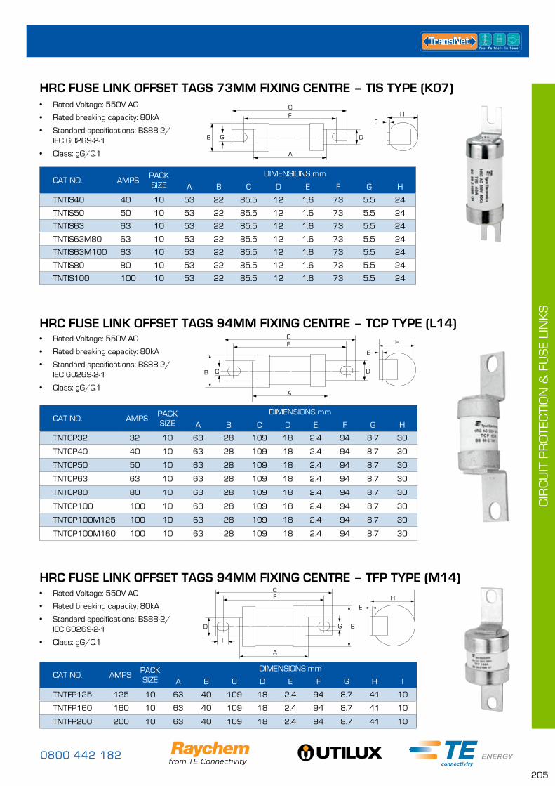
0800 442 182
205
CIR
CU
IT P
RO
TEC
TIO
N &
FU
SE
LIN
KS
HRC FUSE LINK OFFSET TAGS 94MM FIXING CENTRE – TCP TYPE (L14)
CAT NO. AMPSPACK SIZE
DIMENSIONS mm
A B C D E F G H
TNTCP32 32 10 63 28 109 18 2.4 94 8.7 30
TNTCP40 40 10 63 28 109 18 2.4 94 8.7 30
TNTCP50 50 10 63 28 109 18 2.4 94 8.7 30
TNTCP63 63 10 63 28 109 18 2.4 94 8.7 30
TNTCP80 80 10 63 28 109 18 2.4 94 8.7 30
TNTCP100 100 10 63 28 109 18 2.4 94 8.7 30
TNTCP100M125 100 10 63 28 109 18 2.4 94 8.7 30
TNTCP100M160 100 10 63 28 109 18 2.4 94 8.7 30
CH
A
G D
FE
B
• Rated Voltage: 550V AC
• Rated breaking capacity: 80kA
• Standard specifications: BS88-2/ IEC 60269-2-1
• Class: gG/Q1
• Rated Voltage: 550V AC
• Rated breaking capacity: 80kA
• Standard specifications: BS88-2/ IEC 60269-2-1
• Class: gG/Q1
CAT NO. AMPSPACK SIZE
DIMENSIONS mm
A B C D E F G H I
TNTFP125 125 10 63 40 109 18 2.4 94 8.7 41 10
TNTFP160 160 10 63 40 109 18 2.4 94 8.7 41 10
TNTFP200 200 10 63 40 109 18 2.4 94 8.7 41 10
HRC FUSE LINK OFFSET TAGS 94MM FIXING CENTRE – TFP TYPE (M14)
A
CF
D G B
E
H
I
• Rated Voltage: 550V AC
• Rated breaking capacity: 80kA
• Standard specifications: BS88-2/ IEC 60269-2-1
• Class: gG/Q1
HRC FUSE LINK OFFSET TAGS 73MM FIXING CENTRE – TIS TYPE (K07)
CAT NO. AMPSPACK SIZE
DIMENSIONS mm
A B C D E F G H
TNTIS40 40 10 53 22 85.5 12 1.6 73 5.5 24
TNTIS50 50 10 53 22 85.5 12 1.6 73 5.5 24
TNTIS63 63 10 53 22 85.5 12 1.6 73 5.5 24
TNTIS63M80 63 10 53 22 85.5 12 1.6 73 5.5 24
TNTIS63M100 63 10 53 22 85.5 12 1.6 73 5.5 24
TNTIS80 80 10 53 22 85.5 12 1.6 73 5.5 24
TNTIS100 100 10 53 22 85.5 12 1.6 73 5.5 24
B
A
C
E
G D
F H
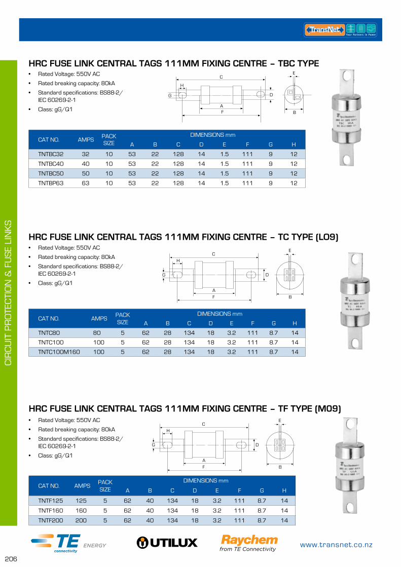
www.transnet.co.nz
206
CIR
CU
IT P
RO
TEC
TIO
N &
FU
SE
LIN
KS
CAT NO. AMPSPACK SIZE
DIMENSIONS mm
A B C D E F G H
TNTBC32 32 10 53 22 128 14 1.5 111 9 12
TNTBC40 40 10 53 22 128 14 1.5 111 9 12
TNTBC50 50 10 53 22 128 14 1.5 111 9 12
TNTBP63 63 10 53 22 128 14 1.5 111 9 12
• Rated Voltage: 550V AC
• Rated breaking capacity: 80kA
• Standard specifications: BS88-2/ IEC 60269-2-1
• Class: gG/Q1
• Rated Voltage: 550V AC
• Rated breaking capacity: 80kA
• Standard specifications: BS88-2/ IEC 60269-2-1
• Class: gG/Q1
HRC FUSE LINK CENTRAL TAGS 111MM FIXING CENTRE – TBC TYPE
HRC FUSE LINK CENTRAL TAGS 111MM FIXING CENTRE – TC TYPE (LO9)
CAT NO. AMPSPACK SIZE
DIMENSIONS mm
A B C D E F G H
TNTC80 80 5 62 28 134 18 3.2 111 8.7 14
TNTC100 100 5 62 28 134 18 3.2 111 8.7 14
TNTC100M160 100 5 62 28 134 18 3.2 111 8.7 14
CH
B
E
A
G
F
D
CAT NO. AMPSPACK SIZE
DIMENSIONS mm
A B C D E F G H
TNTF125 125 5 62 40 134 18 3.2 111 8.7 14
TNTF160 160 5 62 40 134 18 3.2 111 8.7 14
TNTF200 200 5 62 40 134 18 3.2 111 8.7 14
HRC FUSE LINK CENTRAL TAGS 111MM FIXING CENTRE – TF TYPE (M09)
CH
B
E
A
G
F
D
• Rated Voltage: 550V AC
• Rated breaking capacity: 80kA
• Standard specifications: BS88-2/ IEC 60269-2-1
• Class: gG/Q1
A
C
G
BF
D
E
H
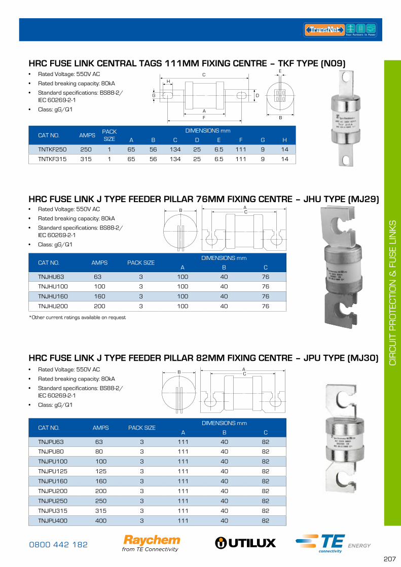
0800 442 182
207
CIR
CU
IT P
RO
TEC
TIO
N &
FU
SE
LIN
KS
CAT NO. AMPSPACK SIZE
DIMENSIONS mm
A B C D E F G H
TNTKF250 250 1 65 56 134 25 6.5 111 9 14
TNTKF315 315 1 65 56 134 25 6.5 111 9 14
• Rated Voltage: 550V AC
• Rated breaking capacity: 80kA
• Standard specifications: BS88-2/ IEC 60269-2-1
• Class: gG/Q1
HRC FUSE LINK CENTRAL TAGS 111MM FIXING CENTRE – TKF TYPE (N09)C
H
B
E
A
G
F
D
• Rated Voltage: 550V AC
• Rated breaking capacity: 80kA
• Standard specifications: BS88-2/ IEC 60269-2-1
• Class: gG/Q1
• Rated Voltage: 550V AC
• Rated breaking capacity: 80kA
• Standard specifications: BS88-2/ IEC 60269-2-1
• Class: gG/Q1
HRC FUSE LINK J TYPE FEEDER PILLAR 82MM FIXING CENTRE – JPU TYPE (MJ30)
CAT NO. AMPS PACK SIZEDIMENSIONS mm
A B C
TNJPU63 63 3 111 40 82
TNJPU80 80 3 111 40 82
TNJPU100 100 3 111 40 82
TNJPU125 125 3 111 40 82
TNJPU160 160 3 111 40 82
TNJPU200 200 3 111 40 82
TNJPU250 250 3 111 40 82
TNJPU315 315 3 111 40 82
TNJPU400 400 3 111 40 82
CAT NO. AMPS PACK SIZEDIMENSIONS mm
A B C
TNJHU63 63 3 100 40 76
TNJHU100 100 3 100 40 76
TNJHU160 160 3 100 40 76
TNJHU200 200 3 100 40 76
HRC FUSE LINK J TYPE FEEDER PILLAR 76MM FIXING CENTRE – JHU TYPE (MJ29)ACB
ACB
*Other current ratings available on request
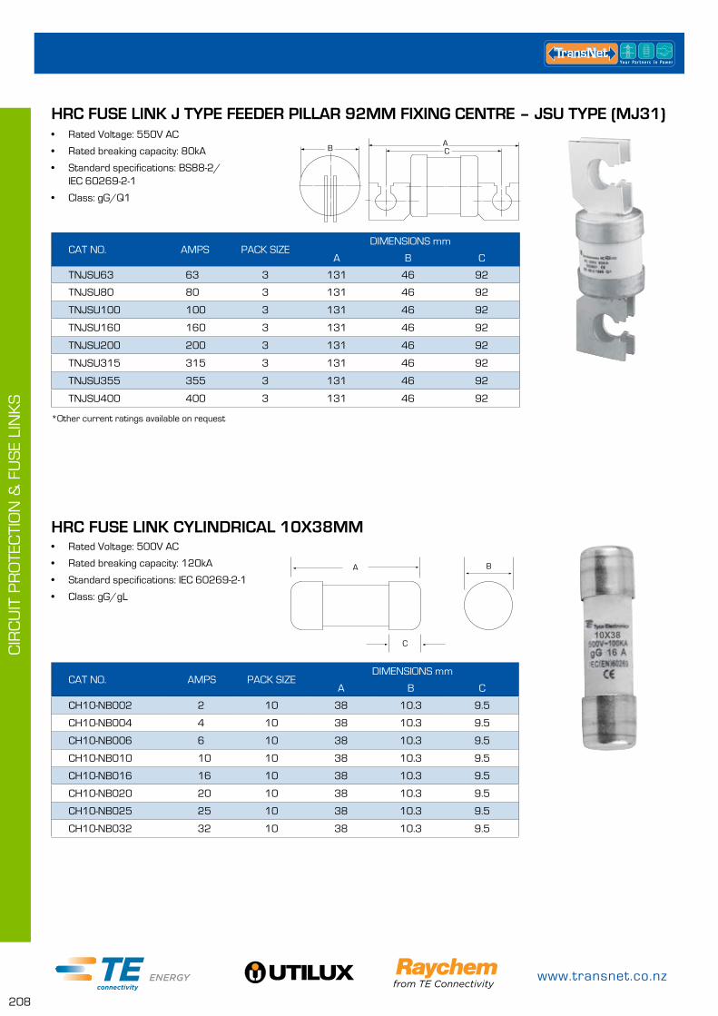
www.transnet.co.nz
208
CIR
CU
IT P
RO
TEC
TIO
N &
FU
SE
LIN
KS
• Rated Voltage: 550V AC
• Rated breaking capacity: 80kA
• Standard specifications: BS88-2/ IEC 60269-2-1
• Class: gG/Q1
HRC FUSE LINK J TYPE FEEDER PILLAR 92MM FIXING CENTRE – JSU TYPE (MJ31)
CAT NO. AMPS PACK SIZEDIMENSIONS mm
A B C
TNJSU63 63 3 131 46 92
TNJSU80 80 3 131 46 92
TNJSU100 100 3 131 46 92
TNJSU160 160 3 131 46 92
TNJSU200 200 3 131 46 92
TNJSU315 315 3 131 46 92
TNJSU355 355 3 131 46 92
TNJSU400 400 3 131 46 92
ACB
*Other current ratings available on request
• Rated Voltage: 500V AC
• Rated breaking capacity: 120kA
• Standard specifications: IEC 60269-2-1
• Class: gG/gL
CAT NO. AMPS PACK SIZEDIMENSIONS mm
A B C
CH10-NB002 2 10 38 10.3 9.5
CH10-NB004 4 10 38 10.3 9.5
CH10-NB006 6 10 38 10.3 9.5
CH10-NB010 10 10 38 10.3 9.5
CH10-NB016 16 10 38 10.3 9.5
CH10-NB020 20 10 38 10.3 9.5
CH10-NB025 25 10 38 10.3 9.5
CH10-NB032 32 10 38 10.3 9.5
HRC FUSE LINK CYLINDRICAL 10X38MM
C
BA
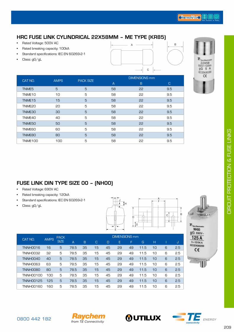
0800 442 182
209
CIR
CU
IT P
RO
TEC
TIO
N &
FU
SE
LIN
KS
CAT NO. AMPS PACK SIZEDIMENSIONS mm
A B C
TNME5 5 5 58 22 9.5
TNME10 10 5 58 22 9.5
TNME15 15 5 58 22 9.5
TNME20 20 5 58 22 9.5
TNME30 30 5 58 22 9.5
TNME40 40 5 58 22 9.5
TNME50 50 5 58 22 9.5
TNME60 60 5 58 22 9.5
TNME80 80 5 58 22 9.5
TNME100 100 5 58 22 9.5
HRC FUSE LINK CYLINDRICAL 22X58MM – ME TYPE (KR85)
C
BA• Rated Voltage: 500V AC
• Rated breaking capacity: 100kA
• Standard specifications: IEC EN 60269-2-1
• Class: gG/gL
• Rated Voltage: 690V AC
• Rated breaking capacity: 120kA
• Standard specifications: IEC EN 60269-2-1
• Class: gG/gL
FUSE LINK DIN TYPE SIZE 00 – (NH00)
H
HJ
C
EI
F
B
G
A
D
CAT NO. AMPS PACK SIZE
DIMENSIONS mm
A B C D E F G H I J
TNNH0016 16 5 78.5 35 15 45 29 49 11.5 10 6 2.5
TNNH0032 32 5 78.5 35 15 45 29 49 11.5 10 6 2.5
TNNH0040 40 5 78.5 35 15 45 29 49 11.5 10 6 2.5
TNNH0063 63 5 78.5 35 15 45 29 49 11.5 10 6 2.5
TNNH0080 80 5 78.5 35 15 45 29 49 11.5 10 6 2.5
TNNH00100 100 5 78.5 35 15 45 29 49 11.5 10 6 2.5
TNNH00125 125 5 78.5 35 15 45 29 49 11.5 10 6 2.5
TNNH00160 160 5 78.5 35 15 45 29 49 11.5 10 6 2.5
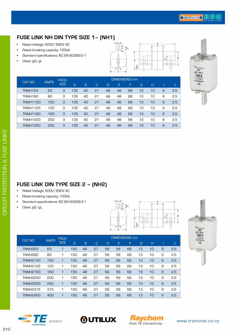
www.transnet.co.nz
210
CIR
CU
IT P
RO
TEC
TIO
N &
FU
SE
LIN
KS
• Rated Voltage: 500V/690V AC
• Rated breaking capacity: 120kA
• Standard specifications: IEC EN 60269-2-1
• Class: gG/gL
• Rated Voltage: 500V/690V AC
• Rated breaking capacity: 120kA
• Standard specifications: IEC EN 60269-2-1
• Class: gG/gL
FUSE LINK DIN TYPE SIZE 2 – (NH2)
CAT NO. AMPS PACK SIZE
DIMENSIONS mm
A B C D E F G H I J
TNNH163 63 3 135 40 21 48 48 68 12 10 6 2.5
TNNH180 80 3 135 40 21 48 48 68 12 10 6 2.5
TNNH1100 100 3 135 40 21 48 48 68 12 10 6 2.5
TNNH1125 125 3 135 40 21 48 48 68 12 10 6 2.5
TNNH1160 160 3 135 40 21 48 48 68 12 10 6 2.5
TNNH1200 200 3 135 40 21 48 48 68 12 10 6 2.5
TNNH1250 250 3 135 40 21 48 48 68 12 10 6 2.5
CAT NO. AMPS PACK SIZE
DIMENSIONS mm
A B C D E F G H I J
TNNH263 63 1 150 48 27 58 58 68 13 10 6 2.5
TNNH280 80 1 150 48 27 58 58 68 13 10 6 2.5
TNNH2100 100 1 150 48 27 58 58 68 13 10 6 2.5
TNNH2125 125 1 150 48 27 58 58 68 13 10 6 2.5
TNNH2160 160 1 150 48 27 58 58 68 13 10 6 2.5
TNNH2200 200 1 150 48 27 58 58 68 13 10 6 2.5
TNNH2250 250 1 150 48 27 58 58 68 13 10 6 2.5
TNNH2315 315 1 150 48 27 58 58 68 13 10 6 2.5
TNNH2400 400 1 150 48 27 58 58 68 13 10 6 2.5
FUSE LINK NH DIN TYPE SIZE 1– (NH1)H
HJ
C
EI
F
B
G
A
D
H
HJ
C
EI
F
B
G
A
D
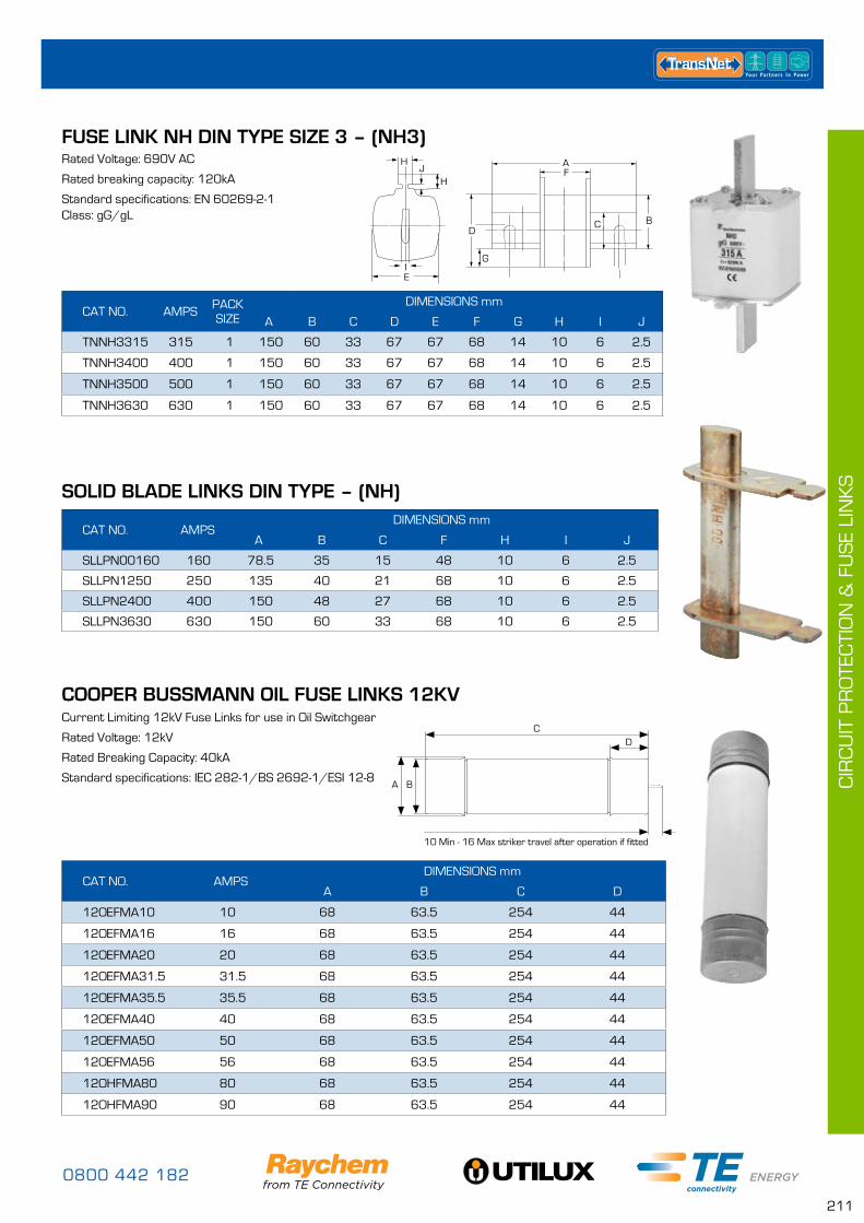
0800 442 182
211
CIR
CU
IT P
RO
TEC
TIO
N &
FU
SE
LIN
KS
COOPER BUSSMANN OIL FUSE LINKS 12KV
CAT NO. AMPSDIMENSIONS mm
A B C D
12OEFMA10 10 68 63.5 254 44
12OEFMA16 16 68 63.5 254 44
12OEFMA20 20 68 63.5 254 44
12OEFMA31.5 31.5 68 63.5 254 44
12OEFMA35.5 35.5 68 63.5 254 44
12OEFMA40 40 68 63.5 254 44
12OEFMA50 50 68 63.5 254 44
12OEFMA56 56 68 63.5 254 44
12OHFMA80 80 68 63.5 254 44
12OHFMA90 90 68 63.5 254 44
Current Limiting 12kV Fuse Links for use in Oil Switchgear
Rated Voltage: 12kV
Rated Breaking Capacity: 40kA
Standard specifications: IEC 282-1/BS 2692-1/ESI 12-8A B
CD
10 Min - 16 Max striker travel after operation if fitted
Rated Voltage: 690V AC
Rated breaking capacity: 120kA
Standard specifications: EN 60269-2-1 Class: gG/gL
CAT NO. AMPS PACK SIZE
DIMENSIONS mm
A B C D E F G H I J
TNNH3315 315 1 150 60 33 67 67 68 14 10 6 2.5
TNNH3400 400 1 150 60 33 67 67 68 14 10 6 2.5
TNNH3500 500 1 150 60 33 67 67 68 14 10 6 2.5
TNNH3630 630 1 150 60 33 67 67 68 14 10 6 2.5
CAT NO. AMPSDIMENSIONS mm
A B C F H I J
SLLPN00160 160 78.5 35 15 48 10 6 2.5
SLLPN1250 250 135 40 21 68 10 6 2.5
SLLPN2400 400 150 48 27 68 10 6 2.5
SLLPN3630 630 150 60 33 68 10 6 2.5
FUSE LINK NH DIN TYPE SIZE 3 – (NH3)
SOLID BLADE LINKS DIN TYPE – (NH)
H
HJ
C
EI
F
B
G
A
D
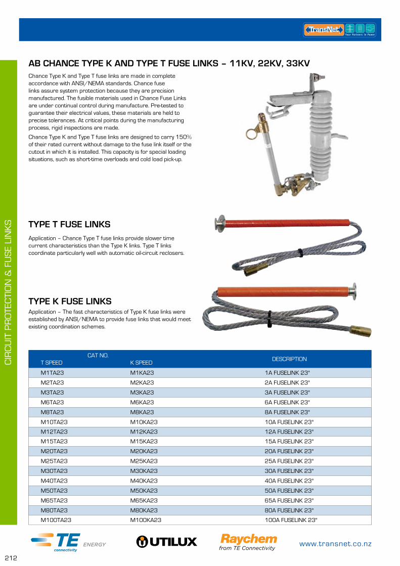
www.transnet.co.nz
212
CIR
CU
IT P
RO
TEC
TIO
N &
FU
SE
LIN
KS
Chance Type K and Type T fuse links are made in complete accordance with ANSI/NEMA standards. Chance fuse links assure system protection because they are precision manufactured. The fusible materials used in Chance Fuse Links are under continual control during manufacture. Pre-tested to guarantee their electrical values, these materials are held to precise tolerances. At critical points during the manufacturing process, rigid inspections are made.
Chance Type K and Type T fuse links are designed to carry 150% of their rated current without damage to the fuse link itself or the cutout in which it is installed. This capacity is for special loading situations, such as short-time overloads and cold load pick-up.
Application – Chance Type T fuse links provide slower time current characteristics than the Type K links. Type T links coordinate particularly well with automatic oil-circuit reclosers.
AB CHANCE TYPE K AND TYPE T FUSE LINKS – 11KV, 22KV, 33KV
TYPE T FUSE LINKS
CAT NO.T SPEED
K SPEED
DESCRIPTION
M1TA23 M1KA23 1A FUSELINK 23"
M2TA23 M2KA23 2A FUSELINK 23"
M3TA23 M3KA23 3A FUSELINK 23"
M6TA23 M6KA23 6A FUSELINK 23"
M8TA23 M8KA23 8A FUSELINK 23"
M10TA23 M10KA23 10A FUSELINK 23"
M12TA23 M12KA23 12A FUSELINK 23"
M15TA23 M15KA23 15A FUSELINK 23"
M20TA23 M20KA23 20A FUSELINK 23"
M25TA23 M25KA23 25A FUSELINK 23"
M30TA23 M30KA23 30A FUSELINK 23"
M40TA23 M40KA23 40A FUSELINK 23"
M50TA23 M50KA23 50A FUSELINK 23"
M65TA23 M65KA23 65A FUSELINK 23"
M80TA23 M80KA23 80A FUSELINK 23"
M100TA23 M100KA23 100A FUSELINK 23"
Application – The fast characteristics of Type K fuse links were established by ANSI/NEMA to provide fuse links that would meet existing coordination schemes.
TYPE K FUSE LINKS
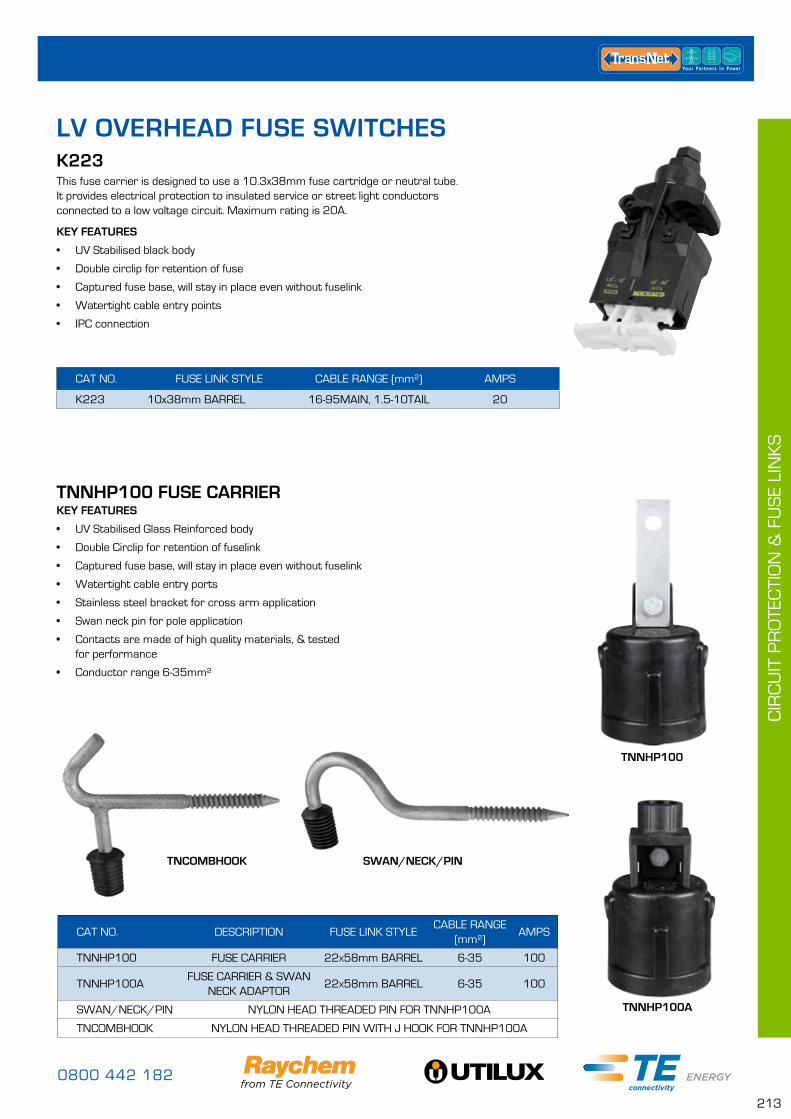
0800 442 182
213
CIR
CU
IT P
RO
TEC
TIO
N &
FU
SE
LIN
KS
LV OVERHEAD FUSE SWITCHES
KEY FEATURES
• UV Stabilised black body
• Double circlip for retention of fuse
• Captured fuse base, will stay in place even without fuselink
• Watertight cable entry points
• IPC connection
CAT NO. FUSE LINK STYLE CABLE RANGE (mm²) AMPS
K223 10x38mm BARREL 16-95MAIN, 1.5-10TAIL 20
K223This fuse carrier is designed to use a 10.3x38mm fuse cartridge or neutral tube. It provides electrical protection to insulated service or street light conductors connected to a low voltage circuit. Maximum rating is 20A.
CAT NO. DESCRIPTION FUSE LINK STYLECABLE RANGE
(mm²)AMPS
TNNHP100 FUSE CARRIER 22x58mm BARREL 6-35 100
TNNHP100AFUSE CARRIER & SWAN
NECK ADAPTOR22x58mm BARREL 6-35 100
SWAN/NECK/PIN NYLON HEAD THREADED PIN FOR TNNHP100A
TNCOMBHOOK NYLON HEAD THREADED PIN WITH J HOOK FOR TNNHP100A
TNNHP100 FUSE CARRIERKEY FEATURES
• UV Stabilised Glass Reinforced body
• Double Circlip for retention of fuselink
• Captured fuse base, will stay in place even without fuselink
• Watertight cable entry ports
• Stainless steel bracket for cross arm application
• Swan neck pin for pole application
• Contacts are made of high quality materials, & tested for performance
• Conductor range 6-35mm²
TNNHP100A
TNNHP100
SWAN/NECK/PINTNCOMBHOOK

www.transnet.co.nz
214
CIR
CU
IT P
RO
TEC
TIO
N &
FU
SE
LIN
KS
BRACKETS
CAT NO. DESCRIPTION
BRAC001 Galvanised Bracket for mounting 1, 2 or 3 fuses (K491, K291, K292)
BRAC001TWISTED Galvanised Bracket for mounting 1, 2 or 3 fuses, Twisted 90° (K491, K291, K292)
BRAC002TWISTED Galvanised Bracket for single mounting, Twisted 90° (K491, K291, K292)
KEY FEATURES
• All brackets are made of galvanised steel highly resistant to corrosion
• Fixing on pole is achieved by bolting galvanised bracket to pole/crossarm
• All brackets will fit all overhead Michaud fittings
• All overhead Michaud fuse corners come with a individual bracket
CAT NO. FUSE LINK STYLE CABLE RANGE (mm²) AMPS
K291 22x58mm BARREL 6-35 100
K292 NH00 6-95 160
K291 & K292This Fuse switch disconnector is a single phase device that is normally used as a house service fuse or isolation point. It provides electrical protection to either an aerial service supplying an individual customer or for a low voltage circuit of a pole mounted transformer.
There are two types of FSD; the K292 suits 160A size 00 DIN fuse links and 240A solid connecting links (according to IEC 269-2.1) and the K291 suits up to 100A 22x58 barrel fuse links (according to IEC 269-2.1). FSD suits aluminium or copper insulated cables from 6 up to 95mm².
BRAC002TWISTEDBRAC001
CAT NO. FUSE LINK STYLE CABLE RANGE (mm²) AMPS
K491 22x58mm BARREL 6-35 100
K491This fuse switch disconnect is a single phase device that is normally used as a house service fuse or isolation point. It provides electrical protection to an individual customer. It is designed to accommodate up to 100A 22x58 size barrel fuse cartridge or neutral tube (according to IEC 269-2.1). It suits aluminium or copper insulated cables from 6 up to 35mm².
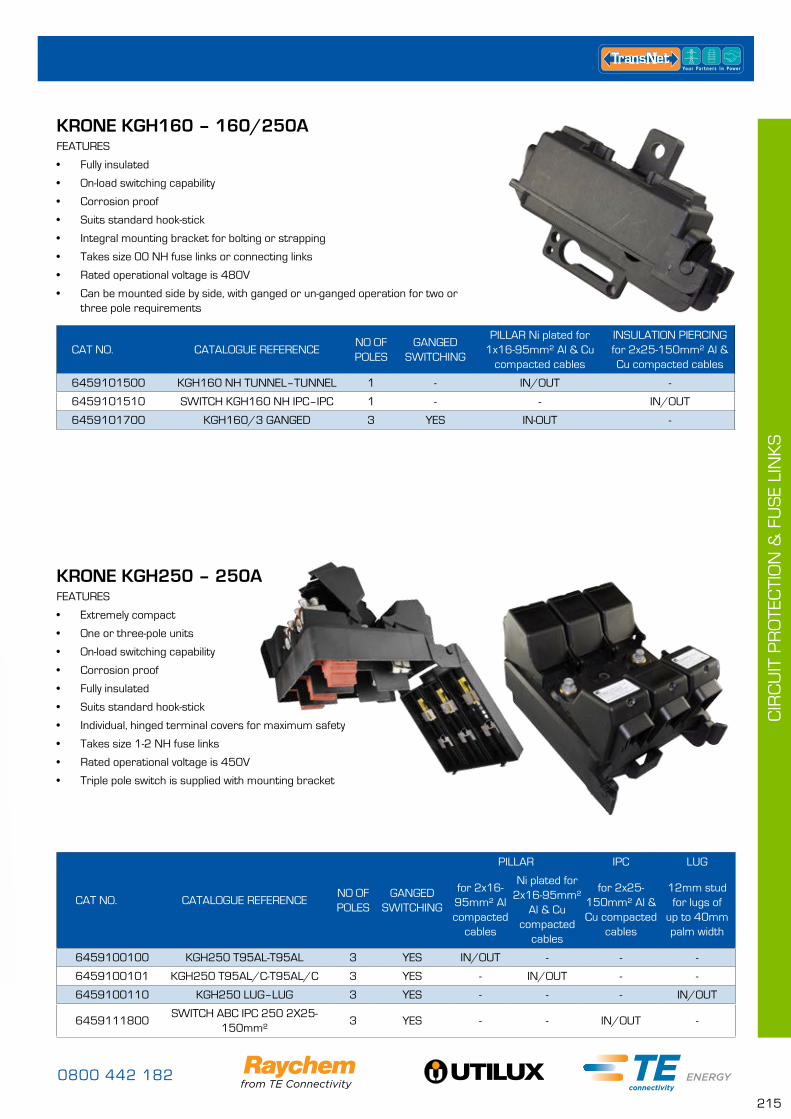
0800 442 182
215
CIR
CU
IT P
RO
TEC
TIO
N &
FU
SE
LIN
KS
KRONE KGH160 – 160/250A FEATURES
• Fully insulated
• On-load switching capability
• Corrosion proof
• Suits standard hook-stick
• Integral mounting bracket for bolting or strapping
• Takes size 00 NH fuse links or connecting links
• Rated operational voltage is 480V
• Can be mounted side by side, with ganged or un-ganged operation for two or three pole requirements
KRONE KGH250 – 250A FEATURES
• Extremely compact
• One or three-pole units
• On-load switching capability
• Corrosion proof
• Fully insulated
• Suits standard hook-stick
• Individual, hinged terminal covers for maximum safety
• Takes size 1-2 NH fuse links
• Rated operational voltage is 450V
• Triple pole switch is supplied with mounting bracket
CAT NO. CATALOGUE REFERENCENO OF POLES
GANGED SWITCHING
PILLAR Ni plated for 1x16-95mm² Al & Cu
compacted cables
INSULATION PIERCING for 2x25-150mm² Al & Cu compacted cables
6459101500 KGH160 NH TUNNEL–TUNNEL 1 - IN/OUT -
6459101510 SWITCH KGH160 NH IPC–IPC 1 - - IN/OUT
6459101700 KGH160/3 GANGED 3 YES IN-OUT -
CAT NO. CATALOGUE REFERENCENO OF POLES
GANGED SWITCHING
PILLAR IPC LUG
for 2x16-95mm² Al compacted
cables
Ni plated for 2x16-95mm²
Al & Cu compacted
cables
for 2x25-150mm² Al & Cu compacted
cables
12mm stud for lugs of
up to 40mm palm width
6459100100 KGH250 T95AL-T95AL 3 YES IN/OUT - - -
6459100101 KGH250 T95AL/C-T95AL/C 3 YES - IN/OUT - -
6459100110 KGH250 LUG–LUG 3 YES - - - IN/OUT
6459111800SWITCH ABC IPC 250 2X25-
150mm²3 YES - - IN/OUT -
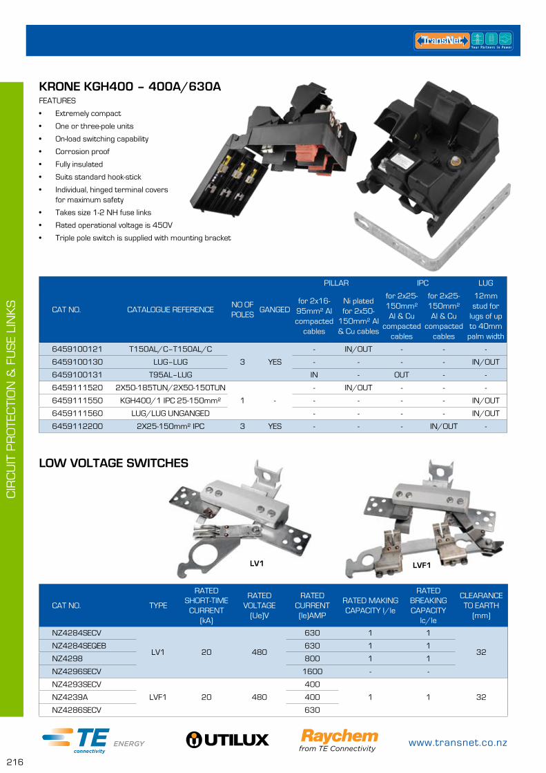
www.transnet.co.nz
216
CIR
CU
IT P
RO
TEC
TIO
N &
FU
SE
LIN
KS
KRONE KGH400 – 400A/630A FEATURES
• Extremely compact
• One or three-pole units
• On-load switching capability
• Corrosion proof
• Fully insulated
• Suits standard hook-stick
• Individual, hinged terminal covers for maximum safety
• Takes size 1-2 NH fuse links
• Rated operational voltage is 450V
• Triple pole switch is supplied with mounting bracket
CAT NO. CATALOGUE REFERENCENO OF POLES
GANGED
PILLAR IPC LUG
for 2x16-95mm² Al compacted
cables
Ni plated for 2x50-
150mm² Al & Cu cables
for 2x25-150mm² Al & Cu
compacted cables
for 2x25-150mm² Al & Cu
compacted cables
12mm stud for
lugs of up to 40mm
palm width
6459100121 T150AL/C–T150AL/C
3 YES
- IN/OUT - - -
6459100130 LUG–LUG - - - - IN/OUT
6459100131 T95AL–LUG IN - OUT - -
6459111520 2X50-185TUN/2X50-150TUN
1 -
- IN/OUT - - -
6459111550 KGH400/1 IPC 25-150mm² - - - - IN/OUT
6459111560 LUG/LUG UNGANGED - - - - IN/OUT
6459112200 2X25-150mm² IPC 3 YES - - - IN/OUT -
CAT NO. TYPE
RATED SHORT-TIME
CURRENT (kA)
RATED VOLTAGE
(Ue)V
RATED CURRENT (le)AMP
RATED MAKING CAPACITY I/le
RATED BREAKING CAPACITY
lc/le
CLEARANCE TO EARTH
(mm)
NZ4284SECV
LV1 20 480
630 1 1
32NZ4284SEQEB 630 1 1
NZ4298 800 1 1
NZ4296SECV 1600 - -
NZ4293SECV
LVF1 20 480
400
1 1 32NZ4239A 400
NZ4286SECV 630
LV1 LVF1
LOW VOLTAGE SWITCHES
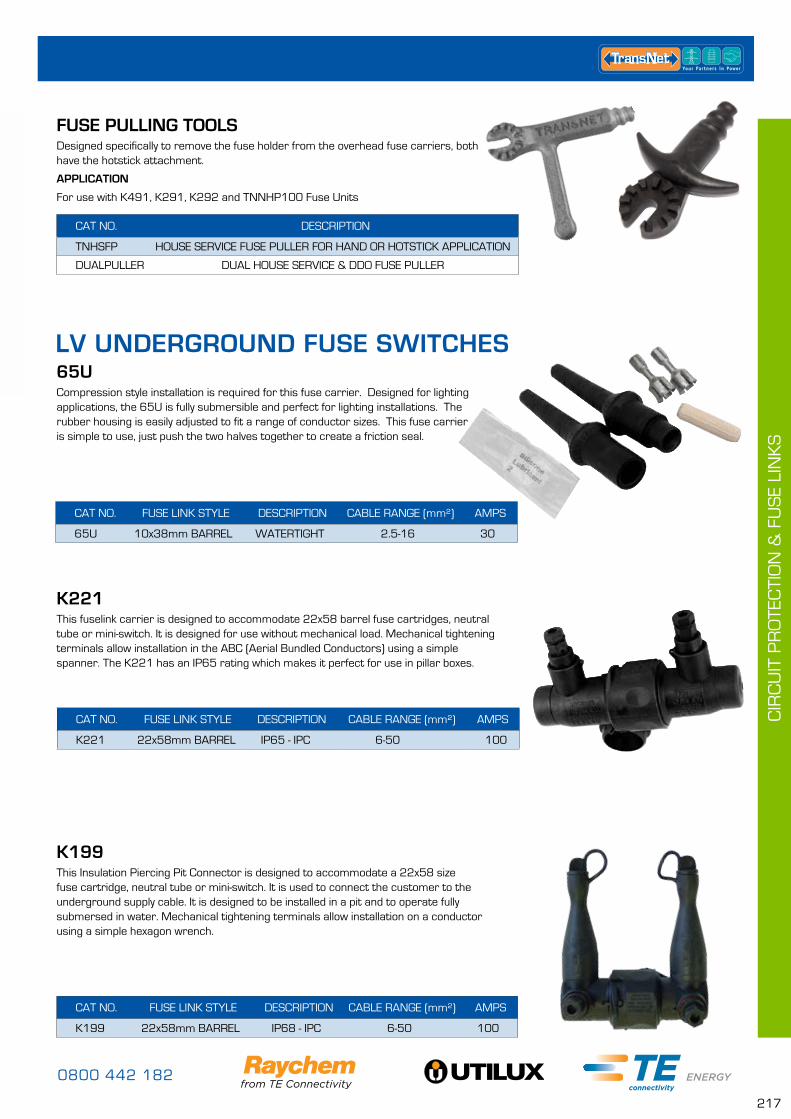
0800 442 182
217
CIR
CU
IT P
RO
TEC
TIO
N &
FU
SE
LIN
KS
LV UNDERGROUND FUSE SWITCHES
CAT NO. FUSE LINK STYLE DESCRIPTION CABLE RANGE (mm²) AMPS
65U 10x38mm BARREL WATERTIGHT 2.5-16 30
65UCompression style installation is required for this fuse carrier. Designed for lighting applications, the 65U is fully submersible and perfect for lighting installations. The rubber housing is easily adjusted to fit a range of conductor sizes. This fuse carrier is simple to use, just push the two halves together to create a friction seal.
CAT NO. FUSE LINK STYLE DESCRIPTION CABLE RANGE (mm²) AMPS
K199 22x58mm BARREL IP68 - IPC 6-50 100
K199This Insulation Piercing Pit Connector is designed to accommodate a 22x58 size fuse cartridge, neutral tube or mini-switch. It is used to connect the customer to the underground supply cable. It is designed to be installed in a pit and to operate fully submersed in water. Mechanical tightening terminals allow installation on a conductor using a simple hexagon wrench.
FUSE PULLING TOOLSDesigned specifically to remove the fuse holder from the overhead fuse carriers, both have the hotstick attachment.
APPLICATION
For use with K491, K291, K292 and TNNHP100 Fuse Units
CAT NO. FUSE LINK STYLE DESCRIPTION CABLE RANGE (mm²) AMPS
K221 22x58mm BARREL IP65 - IPC 6-50 100
K221This fuselink carrier is designed to accommodate 22x58 barrel fuse cartridges, neutral tube or mini-switch. It is designed for use without mechanical load. Mechanical tightening terminals allow installation in the ABC (Aerial Bundled Conductors) using a simple spanner. The K221 has an IP65 rating which makes it perfect for use in pillar boxes.
CAT NO. DESCRIPTION
TNHSFP HOUSE SERVICE FUSE PULLER FOR HAND OR HOTSTICK APPLICATION
DUALPULLER DUAL HOUSE SERVICE & DDO FUSE PULLER
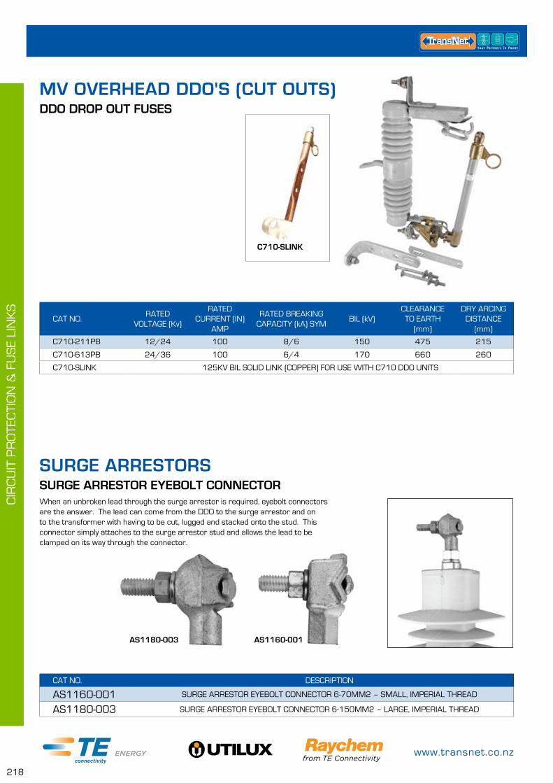
www.transnet.co.nz
218
CIR
CU
IT P
RO
TEC
TIO
N &
FU
SE
LIN
KS
MV OVERHEAD DDO'S (CUT OUTS)DDO DROP OUT FUSES
SURGE ARRESTORS
CAT NO.RATED
VOLTAGE (Kv)
RATED CURRENT (IN)
AMP
RATED BREAKING CAPACITY (kA) SYM
BIL (kV)CLEARANCE TO EARTH
(mm)
DRY ARCING DISTANCE
(mm)
C710-211PB 12/24 100 8/6 150 475 215
C710-613PB 24/36 100 6/4 170 660 260
C710-SLINK 125KV BIL SOLID LINK (COPPER) FOR USE WITH C710 DDO UNITS
CAT NO. DESCRIPTION
AS1160-001 SURGE ARRESTOR EYEBOLT CONNECTOR 6-70MM2 – SMALL, IMPERIAL THREAD
AS1180-003 SURGE ARRESTOR EYEBOLT CONNECTOR 6-150MM2 – LARGE, IMPERIAL THREAD
SURGE ARRESTOR EYEBOLT CONNECTORWhen an unbroken lead through the surge arrestor is required, eyebolt connectors are the answer. The lead can come from the DDO to the surge arrestor and on to the transformer with having to be cut, lugged and stacked onto the stud. This connector simply attaches to the surge arrestor stud and allows the lead to be clamped on its way through the connector.
AS1180-003 AS1160-001
C710-SLINK
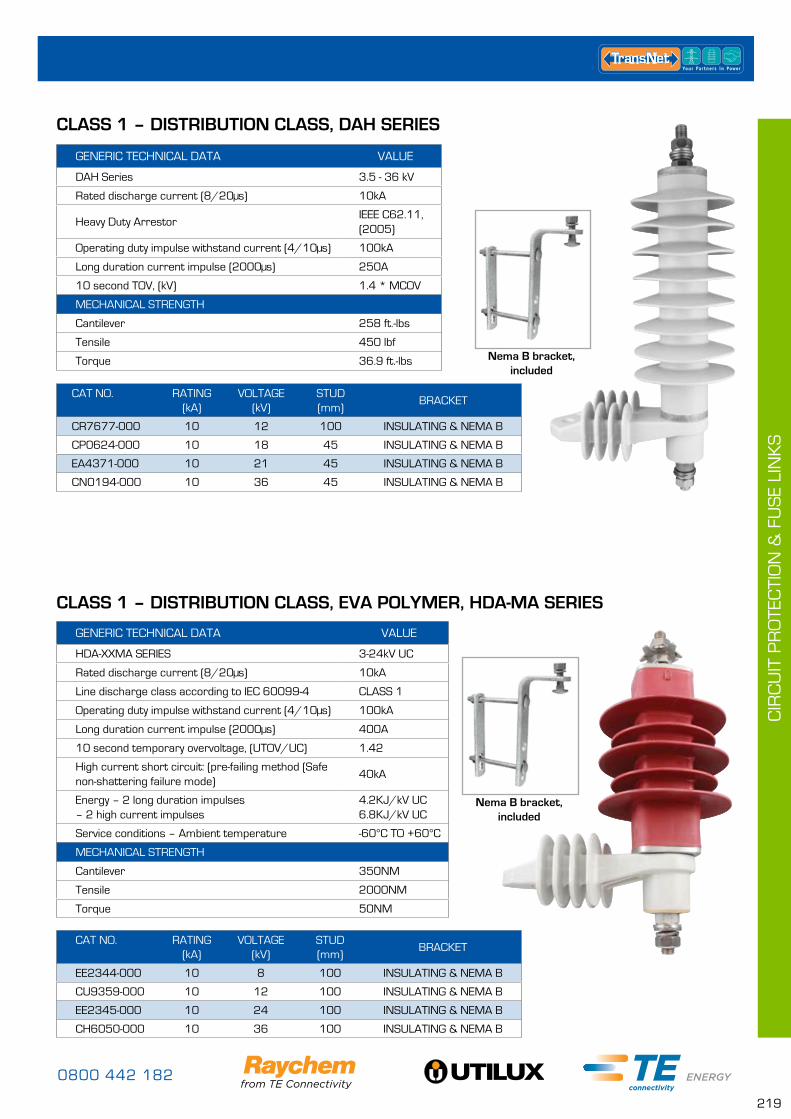
0800 442 182
219
CIR
CU
IT P
RO
TEC
TIO
N &
FU
SE
LIN
KS
CLASS 1 – DISTRIBUTION CLASS, EVA POLYMER, HDA-MA SERIES
GENERIC TECHNICAL DATA VALUE
HDA-XXMA SERIES 3-24kV UC
Rated discharge current (8/20µs) 10kA
Line discharge class according to IEC 60099-4 CLASS 1
Operating duty impulse withstand current (4/10µs) 100kA
Long duration current impulse (2000µs) 400A
10 second temporary overvoltage, (UTOV/UC) 1.42
High current short circuit: (pre-failing method (Safe non-shattering failure mode)
40kA
Energy – 2 long duration impulses – 2 high current impulses
4.2KJ/kV UC 6.8KJ/kV UC
Service conditions – Ambient temperature -60°C TO +60°C
MECHANICAL STRENGTH
Cantilever 350NM
Tensile 2000NM
Torque 50NM
GENERIC TECHNICAL DATA VALUE
DAH Series 3.5 - 36 kV
Rated discharge current (8/20µs) 10kA
Heavy Duty ArrestorIEEE C62.11, (2005)
Operating duty impulse withstand current (4/10µs) 100kA
Long duration current impulse (2000µs) 250A
10 second TOV, (kV) 1.4 * MCOV
MECHANICAL STRENGTH
Cantilever 258 ft.-lbs
Tensile 450 lbf
Torque 36.9 ft.-lbs
CLASS 1 – DISTRIBUTION CLASS, DAH SERIES
CAT NO. RATING (kA)
VOLTAGE (kV)
STUD (mm)
BRACKET
CR7677-000 10 12 100 INSULATING & NEMA B
CP0624-000 10 18 45 INSULATING & NEMA B
EA4371-000 10 21 45 INSULATING & NEMA B
CN0194-000 10 36 45 INSULATING & NEMA B
CAT NO. RATING (kA)
VOLTAGE (kV)
STUD (mm)
BRACKET
EE2344-000 10 8 100 INSULATING & NEMA B
CU9359-000 10 12 100 INSULATING & NEMA B
EE2345-000 10 24 100 INSULATING & NEMA B
CH6050-000 10 36 100 INSULATING & NEMA B
Nema B bracket, included
Nema B bracket, included
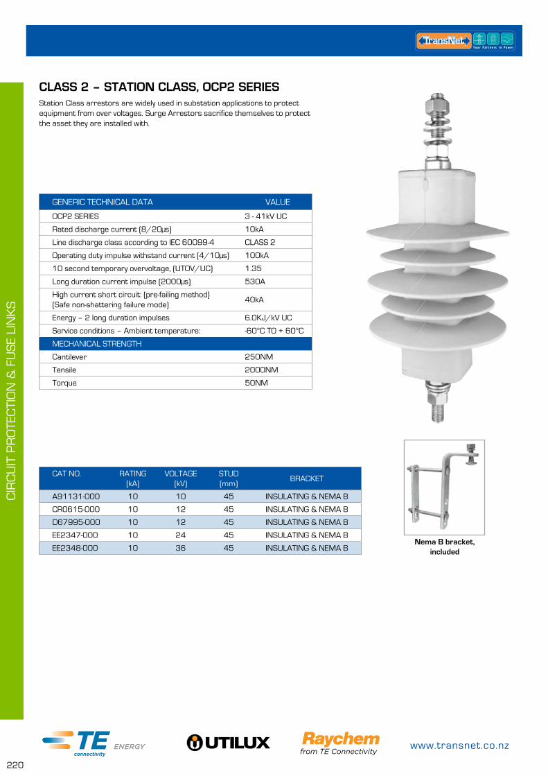
www.transnet.co.nz
220
CIR
CU
IT P
RO
TEC
TIO
N &
FU
SE
LIN
KS
CAT NO. RATING (kA)
VOLTAGE (kV)
STUD (mm)
BRACKET
A91131-000 10 10 45 INSULATING & NEMA B
CR0615-000 10 12 45 INSULATING & NEMA B
D67995-000 10 12 45 INSULATING & NEMA B
EE2347-000 10 24 45 INSULATING & NEMA B
EE2348-000 10 36 45 INSULATING & NEMA B
CLASS 2 – STATION CLASS, OCP2 SERIESStation Class arrestors are widely used in substation applications to protect equipment from over voltages. Surge Arrestors sacrifice themselves to protect the asset they are installed with.
GENERIC TECHNICAL DATA VALUE
OCP2 SERIES 3 - 41kV UC
Rated discharge current (8/20µs) 10kA
Line discharge class according to IEC 60099-4 CLASS 2
Operating duty impulse withstand current (4/10µs) 100kA
10 second temporary overvoltage, (UTOV/UC) 1.35
Long duration current impulse (2000µs) 530A
High current short circuit: (pre-failing method) (Safe non-shattering failure mode)
40kA
Energy – 2 long duration impulses 6.0KJ/kV UC
Service conditions – Ambient temperature: -60°C TO + 60°C
MECHANICAL STRENGTH
Cantilever 250NM
Tensile 2000NM
Torque 50NM
Nema B bracket, included
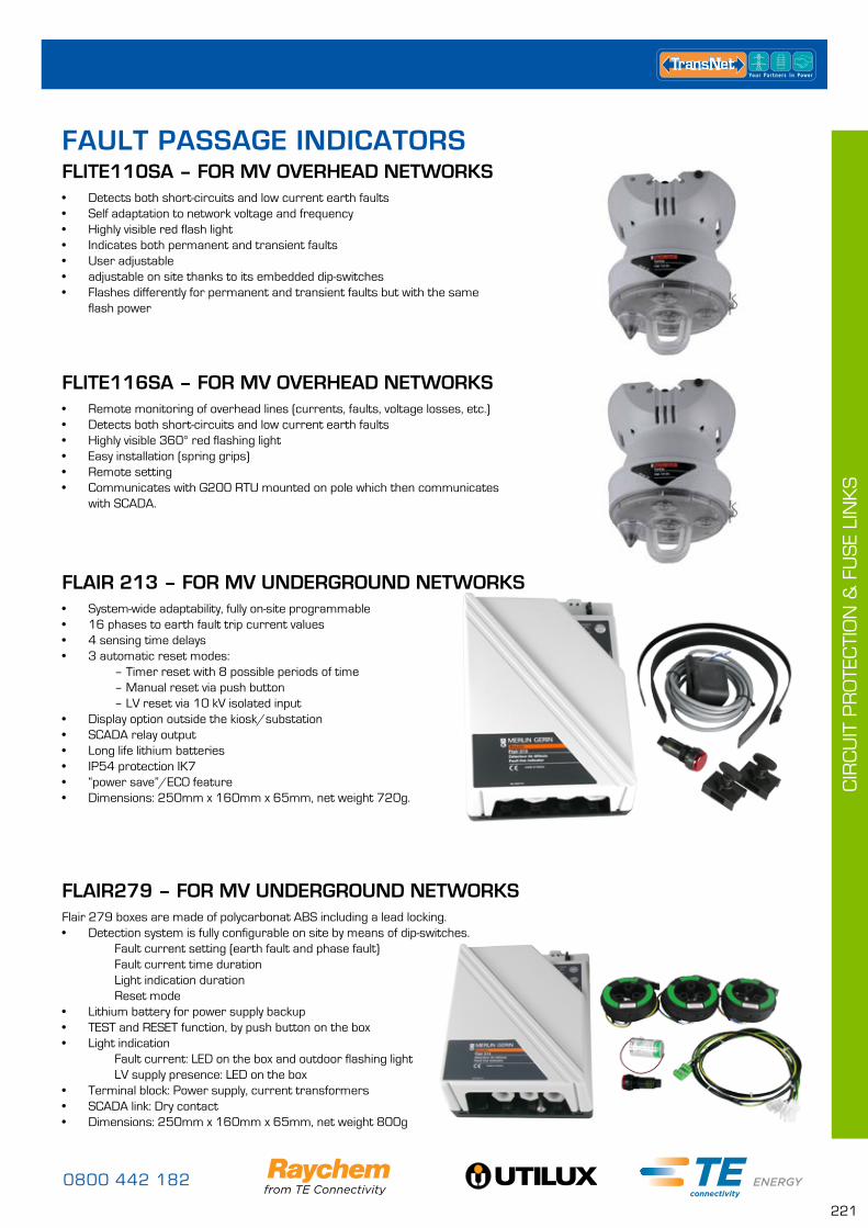
0800 442 182
221
CIR
CU
IT P
RO
TEC
TIO
N &
FU
SE
LIN
KS
• Detects both short-circuits and low current earth faults• Self adaptation to network voltage and frequency• Highly visible red flash light• Indicates both permanent and transient faults• User adjustable• adjustable on site thanks to its embedded dip-switches• Flashes differently for permanent and transient faults but with the same
flash power
FLITE110SA – FOR MV OVERHEAD NETWORKSFAULT PASSAGE INDICATORS
• Remote monitoring of overhead lines (currents, faults, voltage losses, etc.)• Detects both short-circuits and low current earth faults• Highly visible 360° red flashing light• Easy installation (spring grips)• Remote setting• Communicates with G200 RTU mounted on pole which then communicates
with SCADA.
FLITE116SA – FOR MV OVERHEAD NETWORKS
Flair 279 boxes are made of polycarbonat ABS including a lead locking.• Detection system is fully configurable on site by means of dip-switches. Fault current setting (earth fault and phase fault) Fault current time duration Light indication duration Reset mode• Lithium battery for power supply backup• TEST and RESET function, by push button on the box• Light indication Fault current: LED on the box and outdoor flashing light LV supply presence: LED on the box• Terminal block: Power supply, current transformers• SCADA link: Dry contact• Dimensions: 250mm x 160mm x 65mm, net weight 800g
FLAIR279 – FOR MV UNDERGROUND NETWORKS
• System-wide adaptability, fully on-site programmable• 16 phases to earth fault trip current values• 4 sensing time delays• 3 automatic reset modes: – Timer reset with 8 possible periods of time – Manual reset via push button – LV reset via 10 kV isolated input• Display option outside the kiosk/substation• SCADA relay output• Long life lithium batteries• IP54 protection IK7• “power save”/ECO feature• Dimensions: 250mm x 160mm x 65mm, net weight 720g.
FLAIR 213 – FOR MV UNDERGROUND NETWORKS
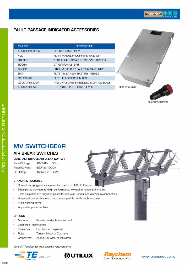
www.transnet.co.nz
222
CIR
CU
IT P
RO
TEC
TIO
N &
FU
SE
LIN
KS
AIR BREAK SWITCHESGENERAL PURPOSE AIR BREAK SWITCH
Rated Voltage 12/24kV to 36kV
Rated Current 800A to 1000A
BIL Rating 150kVp to 200kVp
STANDARD FEATURES
• Current carrying parts are manufactured from HD.HC. Copper.
• Silver plated contacts for high performance, low maintenance and long life.
• Terminal palms are bright tin plated for use with Copper and Aluminium connectors.
• Hinge end contact blade so that current path is not through pivot joint.
• Flicker arcing horns
• Adjustable phase centres
OPTIONS
• Mounting: Pole top, mid pole and vertical
• Load break interrupters
• Insulators: Porcelain or Polymeric
• Poles: Timber, Metal or Concrete
• Crossarms: Aluminium, Steel or Insulated
Consult TransNet for your specific requirements
MV SWITCHGEAR
CAT NO. DESCRIPTION
FLAIRREDBUTTON LED RED LAMP ONLY
VVD FLAIR VANDEL PROOF PERSPEX LAMP
3TCRKIT 1PKT FLAIR 3 SMALL CT'S C/W HARNESS
59964 CT FOR FLAIR213KIT
59982 LITHIUM BATTERY FAULT PASSAGE INDIC
BAT1 FLITE 11x LITHIUM BATTERY - 59982
C1090946 FLITE LFI APPLICATION TOOL
G200-GPRS-DNP RTU DNP3 GPRS EMBEDDED 6 DRY CONTACT
FLAIR2XXCOVER F.I. S/STEEL PROTECTIVE COVER
FAULT PASSAGE INDICATOR ACCESSORIES
FLAIR2XXCOVER
FLAIRREDBUTTON
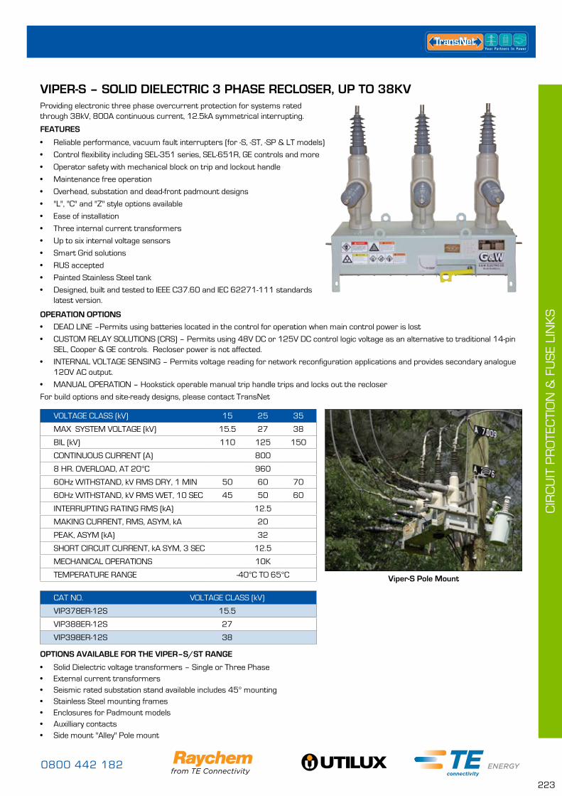
0800 442 182
223
CIR
CU
IT P
RO
TEC
TIO
N &
FU
SE
LIN
KS
VIPER-S – SOLID DIELECTRIC 3 PHASE RECLOSER, UP TO 38KVProviding electronic three phase overcurrent protection for systems rated through 38kV, 800A continuous current, 12.5kA symmetrical interrupting.
FEATURES
• Reliable performance, vacuum fault interrupters (for -S, -ST, -SP & LT models)
• Control flexibility including SEL-351 series, SEL-651R, GE controls and more
• Operator safety with mechanical block on trip and lockout handle
• Maintenance free operation
• Overhead, substation and dead-front padmount designs
• "L", "C" and "Z" style options available
• Ease of installation
• Three internal current transformers
• Up to six internal voltage sensors
• Smart Grid solutions
• RUS accepted
• Painted Stainless Steel tank
• Designed, built and tested to IEEE C37.60 and IEC 62271-111 standards latest version.
OPERATION OPTIONS
• DEAD LINE –Permits using batteries located in the control for operation when main control power is lost
• CUSTOM RELAY SOLUTIONS (CRS) – Permits using 48V DC or 125V DC control logic voltage as an alternative to traditional 14-pin SEL, Cooper & GE controls. Recloser power is not affected.
• INTERNAL VOLTAGE SENSING – Permits voltage reading for network reconfiguration applications and provides secondary analogue 120V AC output.
• MANUAL OPERATION – Hookstick operable manual trip handle trips and locks out the recloser
For build options and site-ready designs, please contact TransNet
OPTIONS AVAILABLE FOR THE VIPER–S/ST RANGE
• Solid Dielectric voltage transformers – Single or Three Phase• External current transformers• Seismic rated substation stand available includes 45° mounting• Stainless Steel mounting frames• Enclosures for Padmount models• Auxilliary contacts• Side mount "Alley" Pole mount
CAT NO. VOLTAGE CLASS (kV)
VIP378ER-12S 15.5
VIP388ER-12S 27
VIP398ER-12S 38
VOLTAGE CLASS (kV) 15 25 35
MAX SYSTEM VOLTAGE (kV) 15.5 27 38
BIL (kV) 110 125 150
CONTINUOUS CURRENT (A) 800
8 HR. OVERLOAD, AT 20°C 960
60Hz WITHSTAND, kV RMS DRY, 1 MIN 50 60 70
60Hz WITHSTAND, kV RMS WET, 10 SEC 45 50 60
INTERRUPTING RATING RMS (kA) 12.5
MAKING CURRENT, RMS, ASYM, kA 20
PEAK, ASYM (kA) 32
SHORT CIRCUIT CURRENT, kA SYM, 3 SEC 12.5
MECHANICAL OPERATIONS 10K
TEMPERATURE RANGE -40°C TO 65°C Viper-S Pole Mount
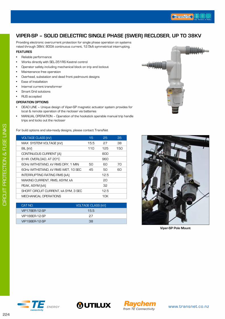
www.transnet.co.nz
224
CIR
CU
IT P
RO
TEC
TIO
N &
FU
SE
LIN
KS
VIPER-SP – SOLID DIELECTRIC SINGLE PHASE (SWER) RECLOSER, UP TO 38KVProviding electronic overcurrent protection for single phase operation on systems rated through 38kV, 800A continuous current, 12.5kA symmetrical interrupting.
FEATURES
• Reliable performance
• Works directly with SEL-351RS Kestrel control
• Operator safety including mechanical block on trip and lockout
• Maintenance free operation
• Overhead, substation and dead front padmount designs
• Ease of Installation
• Internal current transformer
• Smart Grid solutions
• RUS accepted
OPERATION OPTIONS
• DEAD LINE – Unique design of Viper-SP magnetic actuator system provides for local & remote operation of the recloser via batteries
• MANUAL OPERATION – Operation of the hookstick operable manual trip handle trips and locks out the recloser
For build options and site-ready designs, please contact TransNet
CAT NO. VOLTAGE CLASS (kV)
VIP178ER-12-SP 15.5
VIP188ER-12-SP 27
VIP198ER-12-SP 38
VOLTAGE CLASS (kV) 15 25 35
MAX SYSTEM VOLTAGE (kV) 15.5 27 38
BIL (kV) 110 125 150
CONTINUOUS CURRENT (A) 800
8 HR. OVERLOAD, AT 20°C 960
60Hz WITHSTAND, kV RMS DRY, 1 MIN 50 60 70
60Hz WITHSTAND, kV RMS WET, 10 SEC 45 50 60
INTERRUPTING RATING RMS (kA) 12.5
MAKING CURRENT, RMS, ASYM, kA 20
PEAK, ASYM (kA) 32
SHORT CIRCUIT CURRENT, kA SYM, 3 SEC 12.5
MECHANICAL OPERATIONS 10K
Viper-SP Pole Mount
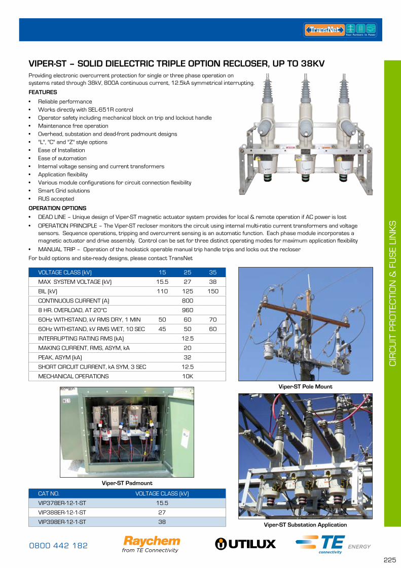
0800 442 182
225
CIR
CU
IT P
RO
TEC
TIO
N &
FU
SE
LIN
KS
VIPER-ST – SOLID DIELECTRIC TRIPLE OPTION RECLOSER, UP TO 38KVProviding electronic overcurrent protection for single or three phase operation on systems rated through 38kV, 800A continuous current, 12.5kA symmetrical interrupting.
FEATURES
• Reliable performance• Works directly with SEL-651R control• Operator safety including mechanical block on trip and lockout handle• Maintenance free operation• Overhead, substation and dead-front padmount designs • "L", "C" and "Z" style options• Ease of Installation• Ease of automation• Internal voltage sensing and current transformers• Application flexibility• Various module configurations for circuit connection flexibility• Smart Grid solutions• RUS accepted
OPERATION OPTIONS
• DEAD LINE – Unique design of Viper-ST magnetic actuator system provides for local & remote operation if AC power is lost
• OPERATION PRINCIPLE – The Viper-ST recloser monitors the circuit using internal multi-ratio current transformers and voltage sensors. Sequence operations, tripping and overcurrent sensing is an automatic function. Each phase module incorporates a magnetic actuator and drive assembly. Control can be set for three distinct operating modes for maximum application flexibility
• MANUAL TRIP – Operation of the hookstick operable manual trip handle trips and locks out the recloser
For build options and site-ready designs, please contact TransNet
CAT NO. VOLTAGE CLASS (kV)
VIP378ER-12-1-ST 15.5
VIP388ER-12-1-ST 27
VIP398ER-12-1-ST 38
VOLTAGE CLASS (kV) 15 25 35
MAX SYSTEM VOLTAGE (kV) 15.5 27 38
BIL (kV) 110 125 150
CONTINUOUS CURRENT (A) 800
8 HR. OVERLOAD, AT 20°C 960
60Hz WITHSTAND, kV RMS DRY, 1 MIN 50 60 70
60Hz WITHSTAND, kV RMS WET, 10 SEC 45 50 60
INTERRUPTING RATING RMS (kA) 12.5
MAKING CURRENT, RMS, ASYM, kA 20
PEAK, ASYM (kA) 32
SHORT CIRCUIT CURRENT, kA SYM, 3 SEC 12.5
MECHANICAL OPERATIONS 10K
Viper-ST Pole Mount
Viper-ST Substation Application
Viper-ST Padmount
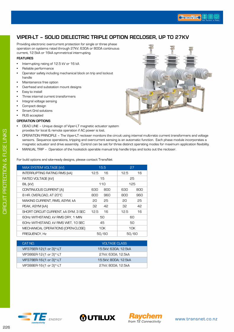
www.transnet.co.nz
226
CIR
CU
IT P
RO
TEC
TIO
N &
FU
SE
LIN
KS
VIPER-LT – SOLID DIELECTRIC TRIPLE OPTION RECLOSER, UP TO 27KVProviding electronic overcurrent protection for single or three phase operation on systems rated through 27kV, 630A or 800A continuous current, 12.5kA or 16kA symmetrical interrupting.
FEATURES
• Interrupting rating of 12.5 kV or 16 kA • Reliable performance• Operator safety including mechanical block on trip and lockout
handle• Maintenance free option• Overhead and substation mount designs• Easy to install• Three internal current transformers• Integral voltage sensing• Compact design• Smart Grid solutions• RUS accepted
OPERATION OPTIONS
• DEAD LINE – Unique design of Viper-LT magnetic actuator system provides for local & remote operation if AC power is lost.
• OPERATION PRINCIPLE – The Viper-LT recloser monitors the circuit using internal multi-ratio current transformers and voltage sensors. Sequence operations, tripping and overcurrent sensing is an automatic function. Each phase module incorporates a magnetic actuator and drive assembly. Control can be set for three distinct operating modes for maximum application flexibility.
• MANUAL TRIP – Operation of the hookstick operable manual trip handle trips and locks out the recloser.
For build options and site-ready designs, please contact TransNet
CAT NO. VOLTAGE CLASS
VIP376ER-12-(1 or 3)*-LT 15.5kV; 630A; 12.5kA
VIP386ER-12-(1 or 3)*-LT 27kV; 630A; 12.5kA
VIP378ER-16-(1 or 3)*-LT 15.5kV; 800A; 12.5kA
VIP388ER-16-(1 or 3)*-LT 27kV; 800A; 12.5kA
MAX SYSTEM VOLTAGE (kV) 15.5 27
INTERRUPTING RATING RMS (kA) 12.5 16 12.5 16
RATED VOLTAGE (kV) 15 25
BIL (kV) 110 125
CONTINUOUS CURRENT (A) 630 800 630 800
8 HR. OVERLOAD, AT 20°C 800 960 800 960
MAKING CURRENT, RMS, ASYM, kA 20 25 20 25
PEAK, ASYM (kA) 32 42 32 42
SHORT CIRCUIT CURRENT, kA SYM, 3 SEC 12.5 16 12.5 16
60Hz WITHSTAND, kV RMS DRY, 1 MIN 50 60
60Hz WITHSTAND, kV RMS WET, 10 SEC 45 50
MECHANICAL OPERATIONS (OPEN-CLOSE) 10K 10K
FREQUENCY, Hz 50/60 50/60
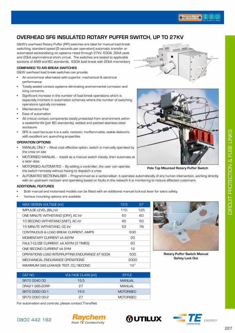
0800 442 182
227
CIR
CU
IT P
RO
TEC
TIO
N &
FU
SE
LIN
KS
OVERHEAD SF6 INSULATED ROTARY PUFFER SWITCH, UP TO 27KVG&W's overhead Rotary Puffer (RP) switches are ideal for manual load break switching, standard speed (5 seconds per operation) automatic transfer or automated sectionalising on systems rated through 27kV, 630A, 32kA peak and 20kA asymmetrical short circuit. The switches are tested to applicable sections of ANSI and IEC standards. 630A load break with 20kA momentary
COMPARED TO AIR BREAK SWITCHES G&W overhead load break switches can provide:
• An economical alternative with superior, mechanical & electrical performance
• Totally sealed contact systems eliminating environmental corrosion and icing concerns
• Significant increase in the number of load break operations which is especially imortant in automation schemes where the number of switching operations typically increases
• Maintenance free• Ease of automation• All critical contact components totally protected from environment within
a sealed-for-life (per IEC standards), welded and painted stainless steel enclosure
• SF6 is used because it is a safe, nontoxic, nonflammable, stable dielectric with excellent arc quenching properties
OPERATION OPTIONS
• MANUAL ONLY – Most cost effective option, switch is manually operated by the crew on site
• MOTORISED MANUAL – Install as a manual switch initially, then automate at a later date
• MOTORISED AUTOMATED – By adding a controller, the user can operate the switch remotely without having to dispatch a crew
• AUTOMATED SECTIONALISER – Programmed as a sectionaliser, it operates automatically of any human intervention, working directly with an upstream recloser and operating based on faults in the network it is monitoring to reduce affected customers.
ADDITIONAL FEATURES
• Both manual and motorised models can be fitted with an additional manual lock-out lever for extra safety.
• Various mounting options are available
CAT NO. VOLTAGE CLASS (kV) STYLE
SR70 0040 00 15.5 MANUAL
ORA21-386-20RP 27 MANUAL
SR70 0060 00-1 15.5 MOTORISED
SR70 0060 00-2 27 MOTORISED
MAX DESIGN VOLTAGE (kV) 15.5 27
IMPULSE LEVEL (BIL) kV 110 125
ONE MINUTE WITHSTAND (DRY), AC kV 50 60
10 SECOND WITHSTAND (WET), AC kV 45 50
15 MINUTE WITHSTAND, DC kV 53 78
CONTINUOUS & LOAD BREAK CURRENT, AMPS 630
MOMENTARY CURRENT kA ASYM 20
FAULT-CLOSE CURRENT, kA ASYM (3 TIMES) 20
ONE SECOND CURRENT kA SYM 12
OPERATIONS LOAD INTERRUPTING ENDURANCE AT 600A 500
MECHANICAL ENDURANCE OPERATIONS 2000
MAXIMUM GAS LEAKAGE TEST, CC/SECOND 10-7
For automation and controls, please contact TransNet
Rotary Puffer Switch Manual Safety Lock Out
Pole Top Mounted Rotary Puffer Switch
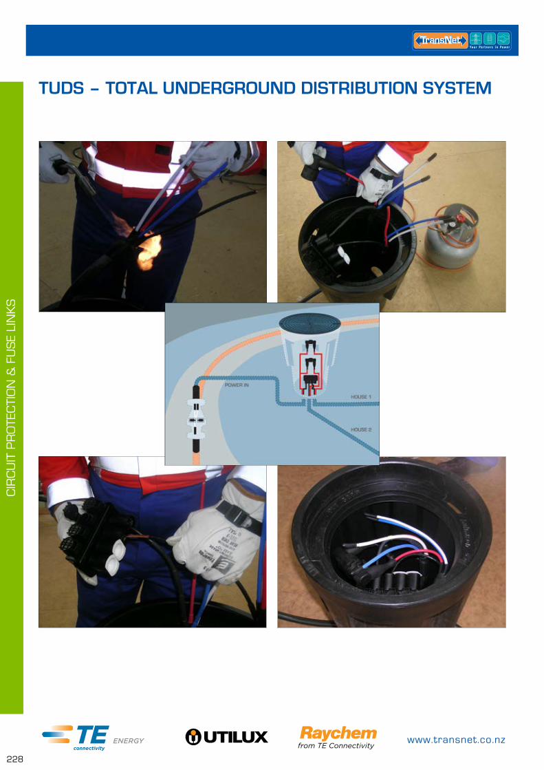
www.transnet.co.nz
228
CIR
CU
IT P
RO
TEC
TIO
N &
FU
SE
LIN
KS
TUDS – TOTAL UNDERGROUND DISTRIBUTION SYSTEM
0800 442 182
229
PIL
LAR
S &
PIT
S
PITS – UNDERGROUND CABLE ENCLOSURES PAGE
TUDS Pits 230
TUDS Pit Lids 230
PIT300D Kits – No Breach Joint 231
TUDS Kits – With Breach Joint 231
TUDS Accessories 232
Buried Cable Enclosure 233
ECOPILLAR – SERVICE PILLARS PAGE
EP0 234
EP1 235
EP2 235
EP2S 236
EP3 236
EP3.5 237
EP4 237
EP6 238
Fuse & Panel Kits 238
LV LINK BOXES & LINK PILLARS PAGE
TAPPAT Link Box 239
TAPPAT 2 Way Link Pillar 239
TAPPAT 3 Way Link Pillar 240
PILLARS & PITS
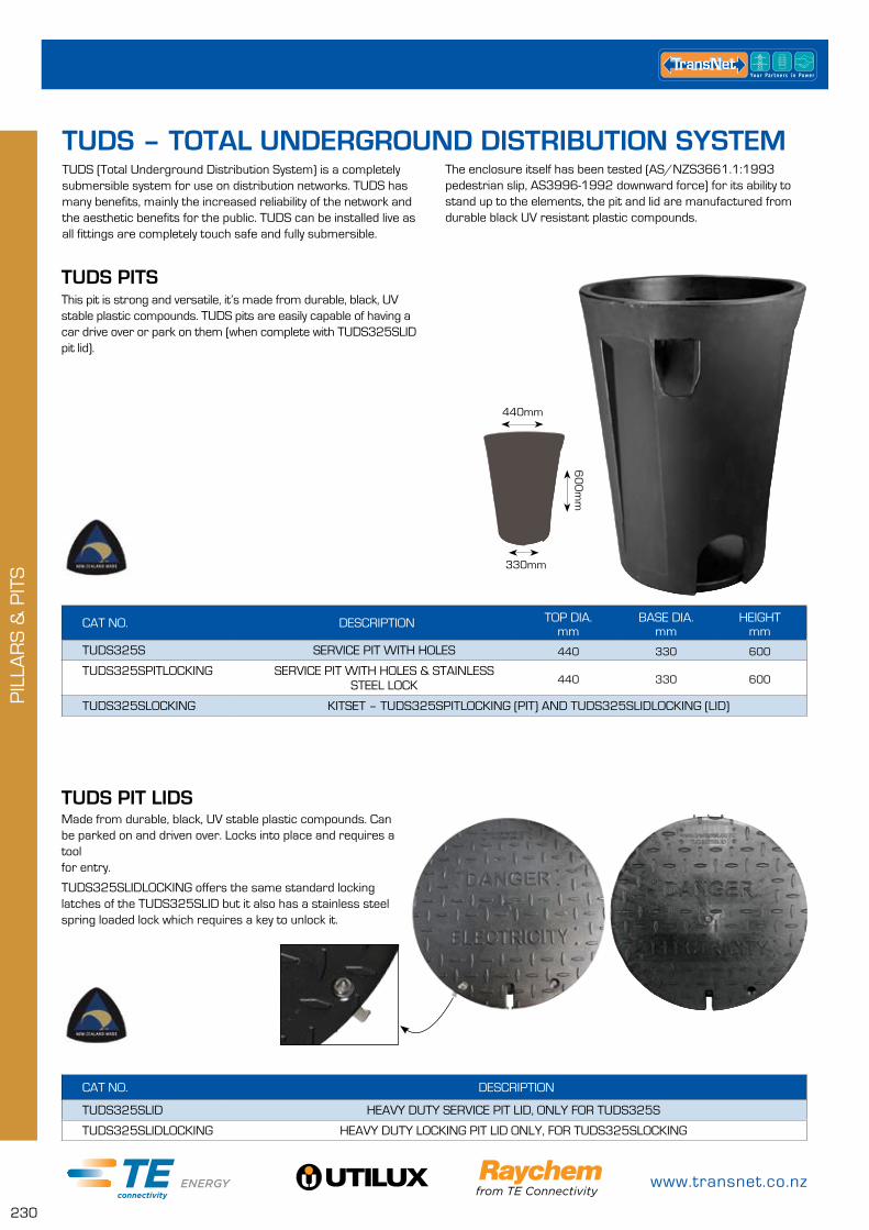
www.transnet.co.nz
230
PIL
LAR
S &
PIT
S
TUDS (Total Underground Distribution System) is a completely submersible system for use on distribution networks. TUDS has many benefits, mainly the increased reliability of the network and the aesthetic benefits for the public. TUDS can be installed live as all fittings are completely touch safe and fully submersible.
The enclosure itself has been tested (AS/NZS3661.1:1993 pedestrian slip, AS3996-1992 downward force) for its ability to stand up to the elements, the pit and lid are manufactured from durable black UV resistant plastic compounds.
TUDS PITS
CAT NO. DESCRIPTION TOP DIA.mm
BASE DIA.mm
HEIGHT mm
TUDS325S SERVICE PIT WITH HOLES 440 330 600
TUDS325SPITLOCKING SERVICE PIT WITH HOLES & STAINLESS STEEL LOCK 440 330 600
TUDS325SLOCKING KITSET – TUDS325SPITLOCKING (PIT) AND TUDS325SLIDLOCKING (LID)
This pit is strong and versatile, it’s made from durable, black, UV stable plastic compounds. TUDS pits are easily capable of having a car drive over or park on them (when complete with TUDS325SLID pit lid).
330mm
440mm
60
0m
m
TUDS PIT LIDSMade from durable, black, UV stable plastic compounds. Can be parked on and driven over. Locks into place and requires a tool for entry.
TUDS325SLIDLOCKING offers the same standard locking latches of the TUDS325SLID but it also has a stainless steel spring loaded lock which requires a key to unlock it.
CAT NO. DESCRIPTION
TUDS325SLID HEAVY DUTY SERVICE PIT LID, ONLY FOR TUDS325S
TUDS325SLIDLOCKING HEAVY DUTY LOCKING PIT LID ONLY, FOR TUDS325SLOCKING
TUDS – TOTAL UNDERGROUND DISTRIBUTION SYSTEM
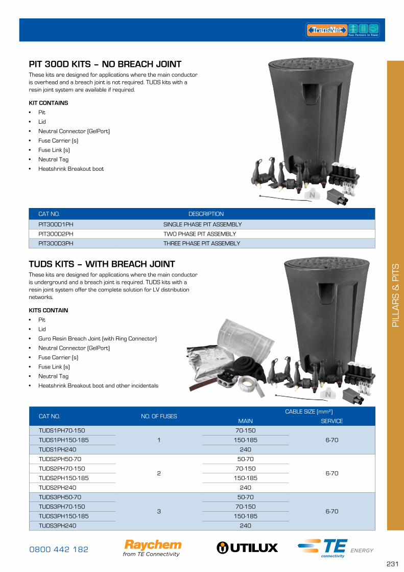
0800 442 182
231
PIL
LAR
S &
PIT
S
PIT 300D KITS – NO BREACH JOINT
CAT NO. DESCRIPTION
PIT300D1PH SINGLE PHASE PIT ASSEMBLY
PIT300D2PH TWO PHASE PIT ASSEMBLY
PIT300D3PH THREE PHASE PIT ASSEMBLY
These kits are designed for applications where the main conductor is overhead and a breach joint is not required. TUDS kits with a resin joint system are available if required.
KIT CONTAINS
• Pit
• Lid
• Neutral Connector (GelPort)
• Fuse Carrier (s)
• Fuse Link (s)
• Neutral Tag
• Heatshrink Breakout boot
CAT NO. NO. OF FUSESCABLE SIZE (mm²)
MAIN SERVICE
TUDS1PH70-150
1
70-150
6-70TUDS1PH150-185 150-185
TUDS1PH240 240
TUDS2PH50-70
2
50-70
6-70TUDS2PH70-150 70-150
TUDS2PH150-185 150-185
TUDS2PH240 240
TUDS3PH50-70
3
50-70
6-70TUDS3PH70-150 70-150
TUDS3PH150-185 150-185
TUDS3PH240 240
TUDS KITS – WITH BREACH JOINTThese kits are designed for applications where the main conductor is underground and a breach joint is required. TUDS kits with a resin joint system offer the complete solution for LV distribution networks.
KITS CONTAIN
• Pit
• Lid
• Guro Resin Breach Joint (with Ring Connector)
• Neutral Connector (GelPort)
• Fuse Carrier (s)
• Fuse Link (s)
• Neutral Tag
• Heatshrink Breakout boot and other incidentals
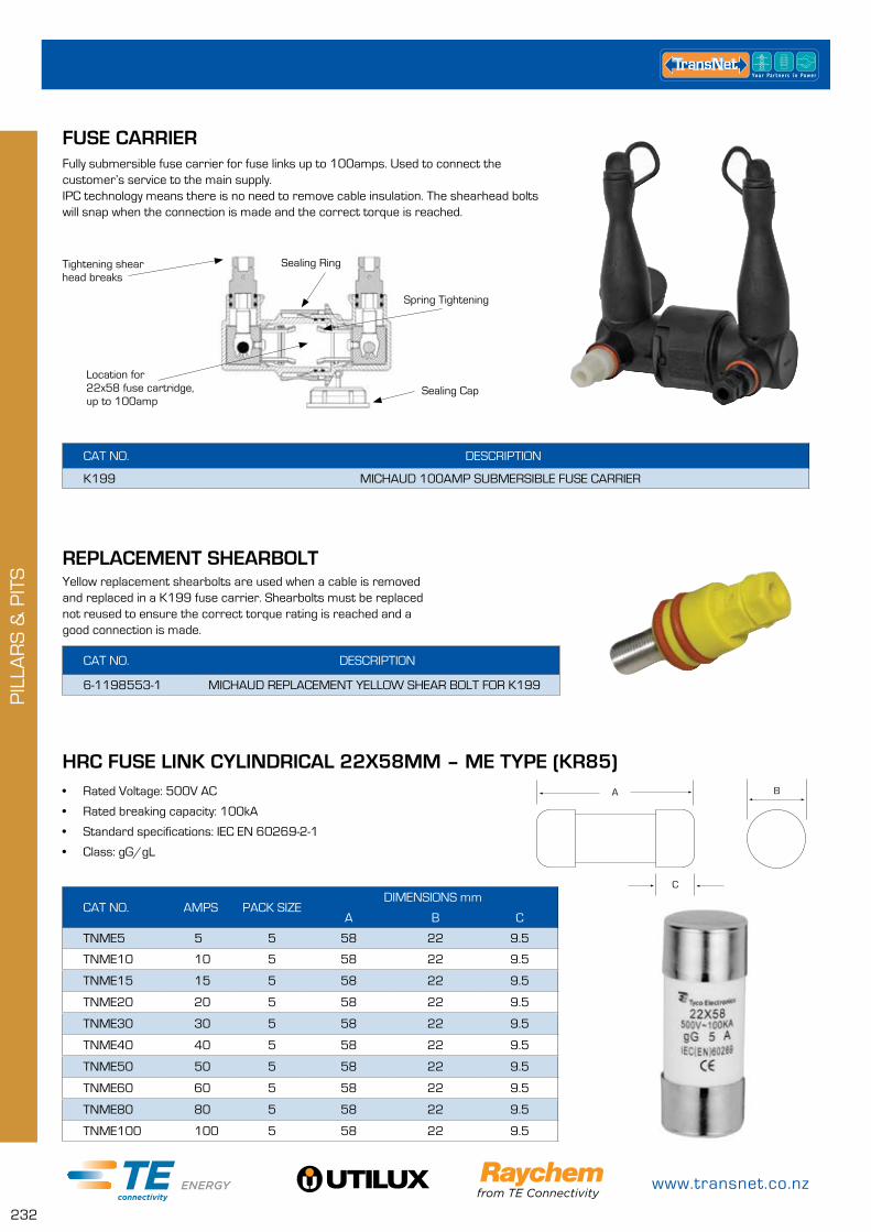
www.transnet.co.nz
232
PIL
LAR
S &
PIT
S
CAT NO. AMPS PACK SIZEDIMENSIONS mm
A B C
TNME5 5 5 58 22 9.5
TNME10 10 5 58 22 9.5
TNME15 15 5 58 22 9.5
TNME20 20 5 58 22 9.5
TNME30 30 5 58 22 9.5
TNME40 40 5 58 22 9.5
TNME50 50 5 58 22 9.5
TNME60 60 5 58 22 9.5
TNME80 80 5 58 22 9.5
TNME100 100 5 58 22 9.5
HRC FUSE LINK CYLINDRICAL 22X58MM – ME TYPE (KR85)
C
BA• Rated Voltage: 500V AC
• Rated breaking capacity: 100kA
• Standard specifications: IEC EN 60269-2-1
• Class: gG/gL
CAT NO. DESCRIPTION
K199 MICHAUD 100AMP SUBMERSIBLE FUSE CARRIER
FUSE CARRIERFully submersible fuse carrier for fuse links up to 100amps. Used to connect the customer’s service to the main supply. IPC technology means there is no need to remove cable insulation. The shearhead bolts will snap when the connection is made and the correct torque is reached.
Sealing Ring
Sealing CapLocation for22x58 fuse cartridge, up to 100amp
Spring Tightening
Tightening shearhead breaks
CAT NO. DESCRIPTION
6-1198553-1 MICHAUD REPLACEMENT YELLOW SHEAR BOLT FOR K199
REPLACEMENT SHEARBOLTYellow replacement shearbolts are used when a cable is removed and replaced in a K199 fuse carrier. Shearbolts must be replaced not reused to ensure the correct torque rating is reached and a good connection is made.
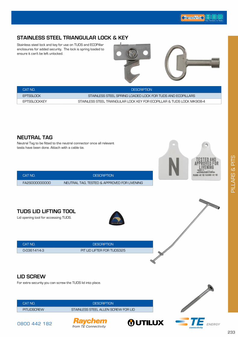
0800 442 182
233
PIL
LAR
S &
PIT
S
CAT NO. DESCRIPTION
FA2S000000000 NEUTRAL TAG, TESTED & APPROVED FOR LIVENING
Neutral Tag to be fitted to the neutral connector once all relevant tests have been done. Attach with a cable tie.
NEUTRAL TAG
TUDS LID LIFTING TOOL
CAT NO. DESCRIPTION
0-0361414-3 PIT LID LIFTER FOR TUDS325
Lid opening tool for accessing TUDS.
CAT NO. DESCRIPTION
EPTSSLOCK STAINLESS STEEL SPRING LOADED LOCK FOR TUDS AND ECOPILLARS
EPTSSLOCKKEY STAINLESS STEEL TRIANGULAR LOCK KEY FOR ECOPILLAR & TUDS LOCK MK908-4
STAINLESS STEEL TRIANGULAR LOCK & KEYStainless steel lock and key for use on TUDS and ECOPillar enclosures for added security. The lock is spring loaded to ensure it can't be left unlocked.
CAT NO. DESCRIPTION
PITLIDSCREW STAINLESS STEEL ALLEN SCREW FOR LID
LID SCREWFor extra security you can screw the TUDS lid into place.
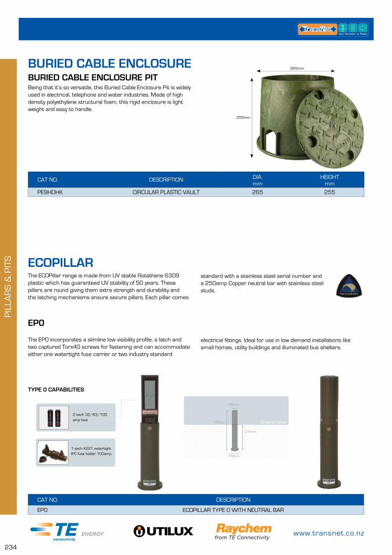
www.transnet.co.nz
234
PIL
LAR
S &
PIT
S
The ECOPillar range is made from UV stable Rotathene 6309 plastic which has guaranteed UV stability of 50 years. These pillars are round giving them extra strength and durability and the latching mechanisms ensure secure pillars. Each pillar comes
EP0
The EP0 incorporates a slimline low visibility profile, a latch and two captured Torx40 screws for fastening and can accommodate either one watertight fuse carrier or two industry standard
CAT NO. DESCRIPTION
EP0 ECOPILLAR TYPE 0 WITH NEUTRAL BAR
TYPE 0 CAPABILITIES
2 each 32/63/100 amp fuse
820mm375mm
350mm
255mm
G/L Ground Level
125mm
375mm
770mm
170mm
standard with a stainless steel serial number and a 250amp Copper neutral bar with stainless steel studs.
electrical fittings. Ideal for use in low demand installations like small homes, utility buildings and illuminated bus shelters.
1 each K221 watertight IPC fuse holder 100amp
ECOPILLAR
BURIED CABLE ENCLOSUREBURIED CABLE ENCLOSURE PIT
CAT NO. DESCRIPTION DIA.mm
HEIGHTmm
PE9HDHK CIRCULAR PLASTIC VAULT 265 255
Being that it’s so versatile, this Buried Cable Enclosure Pit is widely used in electrical, telephone and water industries. Made of high density polyethylene structural foam, this rigid enclosure is light weight and easy to handle.
255mm
265mm
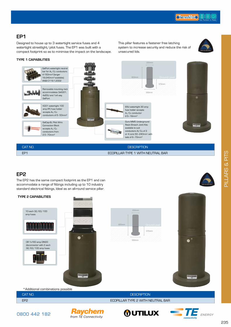
0800 442 182
235
PIL
LAR
S &
PIT
S
EP1Designed to house up to 3 watertight service fuses and 4 watertight streetlight/pilot fuses. The EP1 was built with a compact footprint so as to minimise the impact on the landscape.
CAT NO. DESCRIPTION
EP1 ECOPILLAR TYPE 1 WITH NEUTRAL BAR
TYPE 1 CAPABILITIES
820mm
375mm
350mm
255mm
G/L820mm
375mm
350mm
255mm
G/LGround Level
65U watertight 30 amp fuse holder accepts Al/Cu conductor 2.5–16mm²
Guro MM5 Underground Resin Breach Joint Kits available to suit conductors Al/Cu of 3 or 4 core 50–240mm² with tails of 6–70mm²
GelPort watertight neutral bar for Al/Cu conductors 4-150mm² (larger 16-240mm² available)
ANSI C119.1,2002
K221 watertight 100 amp IPC fuse holder accepts Al/Cu conductors of 6–50mm²
GelCap-SL Pilot Wire Connection Block accepts Al/Cu conductors from 2.5–70mm²
Removable mounting rack accommodates 3xK221, 4x65U and 1x4 way GelPort
This pillar features a fastener free latching system to increase security and reduce the risk of unsecured lids.
EP2The EP2 has the same compact footprint as the EP1 and can accommodate a range of fittings including up to 10 industry standard electrical fittings, Ideal as an all-round service pillar.
CAT NO. DESCRIPTION
EP2 ECOPILLAR TYPE 2 WITH NEUTRAL BAR
820mm
375mm
350mm
255mm
G/L Ground Level820mm
375mm
350mm
255mm
G/L
TYPE 2 CAPABILITIES
10 each 32/63/100 amp fuses
OR 1x160 amp DIN00 disconnector with 2 each 32/63/100 amp fuses
*Additional combinations possible
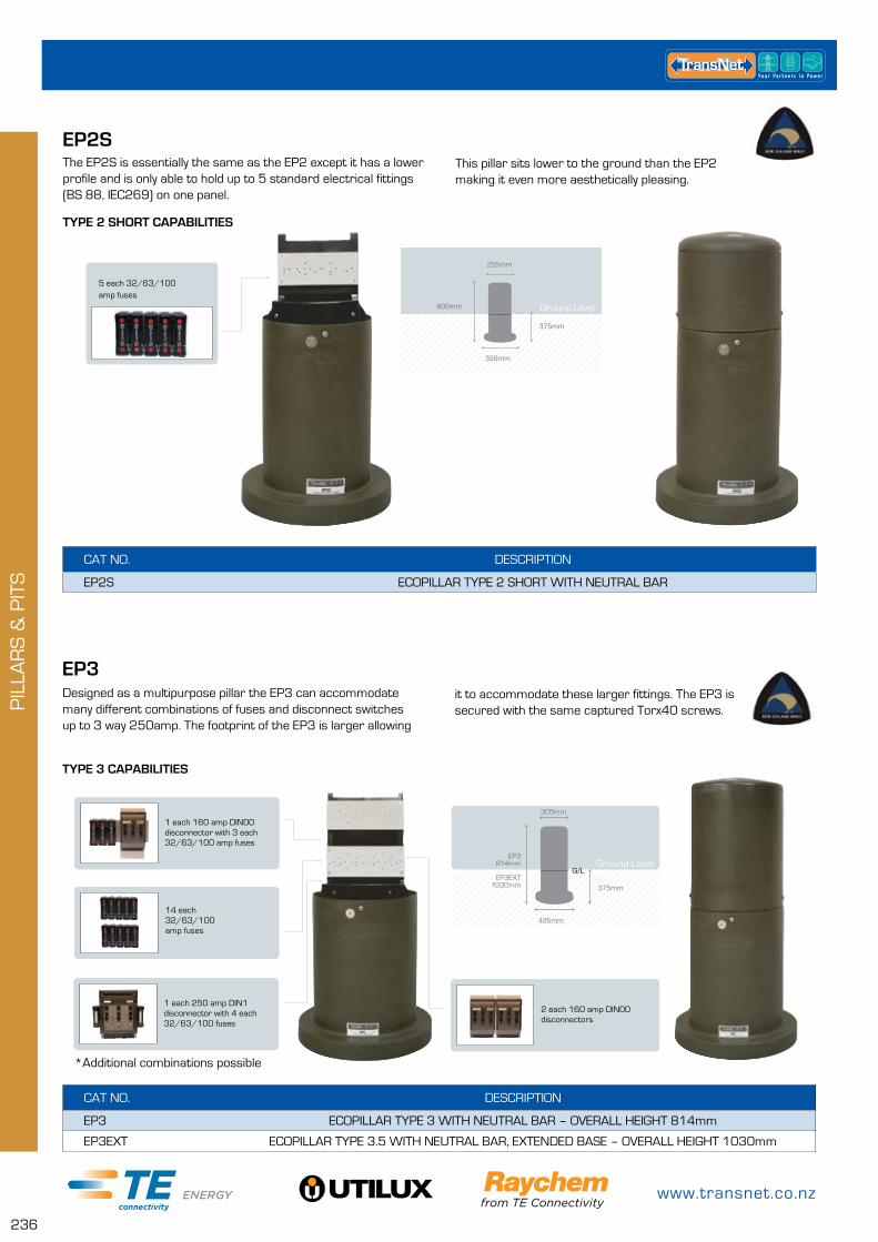
www.transnet.co.nz
236
PIL
LAR
S &
PIT
S
EP3Designed as a multipurpose pillar the EP3 can accommodate many different combinations of fuses and disconnect switches up to 3 way 250amp. The footprint of the EP3 is larger allowing
CAT NO. DESCRIPTION
EP3 ECOPILLAR TYPE 3 WITH NEUTRAL BAR – OVERALL HEIGHT 814mm
EP3EXT ECOPILLAR TYPE 3.5 WITH NEUTRAL BAR, EXTENDED BASE – OVERALL HEIGHT 1030mm
TYPE 3 CAPABILITIES
14 each 32/63/100 amp fuses
1 each 250 amp DIN1 disconnector with 4 each 32/63/100 fuses
1 each 160 amp DIN00 disconnector with 3 each 32/63/100 amp fuses
2 each 160 amp DIN00 disconnectors
Ground Level
it to accommodate these larger fittings. The EP3 is secured with the same captured Torx40 screws.
405mm
305mm
820mm
375mm
G/L
305mm
EP2SThe EP2S is essentially the same as the EP2 except it has a lower profile and is only able to hold up to 5 standard electrical fittings (BS 88, IEC269) on one panel.
CAT NO. DESCRIPTION
EP2S ECOPILLAR TYPE 2 SHORT WITH NEUTRAL BAR
TYPE 2 SHORT CAPABILITIES
600mm
375mm
255mm
350mm
G/LGround Level
5 each 32/63/100 amp fuses
This pillar sits lower to the ground than the EP2 making it even more aesthetically pleasing.
EP3 814mm
EP3EXT 1030mm
*Additional combinations possible
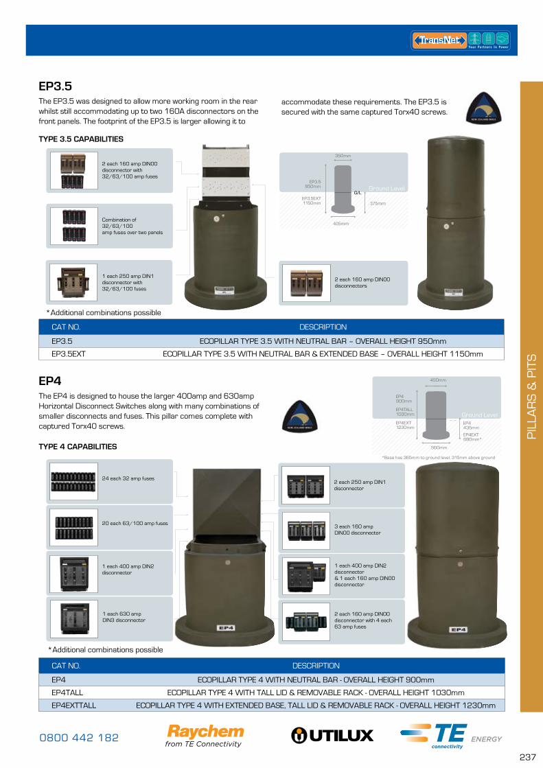
0800 442 182
237
PIL
LAR
S &
PIT
S
EP4The EP4 is designed to house the larger 400amp and 630amp Horizontal Disconnect Switches along with many combinations of smaller disconnects and fuses. This pillar comes complete with captured Torx40 screws.
CAT NO. DESCRIPTION
EP4 ECOPILLAR TYPE 4 WITH NEUTRAL BAR - OVERALL HEIGHT 900mm
EP4TALL ECOPILLAR TYPE 4 WITH TALL LID & REMOVABLE RACK - OVERALL HEIGHT 1030mm
EP4EXTTALL ECOPILLAR TYPE 4 WITH EXTENDED BASE, TALL LID & REMOVABLE RACK - OVERALL HEIGHT 1230mm
TYPE 4 CAPABILITIES 405mm
305mm
820mm
375mm
G/L
405mm
305mm
820mm
375mm
G/LGround Level
450mm
EP4TALL 1030mm
560mm
EP4 435mm
1 each 630 amp DIN3 disconnector
1 each 400 amp DIN2 disconnector
24 each 32 amp fuses
20 each 63/100 amp fuses3 each 160 amp DIN00 disconnector
2 each 160 amp DIN00 disconnector with 4 each 63 amp fuses
1 each 400 amp DIN2 disconnector & 1 each 160 amp DIN00 disconnector
2 each 250 amp DIN1 disconnector
*Additional combinations possible
EP4EXT 1230mm
EP4EXT 680mm*
*Base has 365mm to ground level, 315mm above ground
EP3.5The EP3.5 was designed to allow more working room in the rear whilst still accommodating up to two 160A disconnectors on the front panels. The footprint of the EP3.5 is larger allowing it to
CAT NO. DESCRIPTION
EP3.5 ECOPILLAR TYPE 3.5 WITH NEUTRAL BAR – OVERALL HEIGHT 950mm
EP3.5EXT ECOPILLAR TYPE 3.5 WITH NEUTRAL BAR & EXTENDED BASE – OVERALL HEIGHT 1150mm
TYPE 3.5 CAPABILITIES
Combination of 32/63/100 amp fuses over two panels
1 each 250 amp DIN1 disconnector with 32/63/100 fuses
2 each 160 amp DIN00 disconnector with 32/63/100 amp fuses
2 each 160 amp DIN00 disconnectors
Ground Level
accommodate these requirements. The EP3.5 is secured with the same captured Torx40 screws.
405mm
305mm
820mm
375mm
G/L
350mm
EP3.5 950mm
EP3.5EXT 1150mm
*Additional combinations possible
EP4 900mm
www.transnet.co.nz
238
PIL
LAR
S &
PIT
S
Will accommodate any number of monitoring or switching devices
Multiple 63/100 amp fuses
160/250/400/630 amp DIN disconnector with 63 amp fuse links if required
PANEL KITSMade from Fire Retardant plastic, ECOPILLAR panels have been injection moulded with holes to accommodate standard electrical
CAT NO. DESCRIPTION
EP0PANELKIT EP0 GREY PVC PANEL DRILLED WITH SCREWS
EP2/2SPANELKIT EP2/2S GREY PVC PANEL DRILLED WITH SCREWS
EP3PANELKIT EP3 GREY PVC PANEL DRILLED WITH SCREWS
EP0PANEL KIT EP2/2SPANEL KIT EP3PANEL KIT
fittings. Panel kits come complete with plastic tapping screws for fastening to pillar body.
EP6The largest and most versatile of the ECOPillar range the EP6 was designed to accommodate the requirements of a network link and junction pillar as well as being capable of housing service fuses, disconnect switches and any number of combinations of hardware.
CAT NO. DESCRIPTION
EP6 ECOPILLAR TYPE 6 WITH NEUTRAL BAR - OVERALL HEIGHT 820MM
EP6TALL ECOPILLAR TYPE 6 WITH NEUTRAL BAR, DOUBLE RACK, TALL LID - OVERALL HEIGHT 1020MM
TYPE 6 CAPABILITIES
Mix of Disconnector switch sizes with additional service fuses if required
The feature setting this pillar apart is the ability to house submersible GelPort connectors in the base.
*Additional combinations possible
405mm
305mm
820mm
375mm
G/L
405mm
305mm
820mm
375mm
G/LGround Level
470mm
EP6 820mm
450mmEP6TALL 1020mm
FUSE KITSThe ECOPillar range is versatile and easy to populate. We have a range of fuse kits available for each of our ECOPillar models and these fuse kits can be supplied separately or installed onto the panel prior to shipping from our store.
CAT NO. DESCRIPTION
EPFUSE32AKIT 32A FUSE AND ASSEMBLY TO PANEL
EPFUSE63AKIT TE 63A FUSE AND ASSEMBLY TO PANEL
EPFUSE100AKIT 100A FUSE AND ASSEMBLY TO PANEL
0800 442 182
239
PIL
LAR
S &
PIT
S
LV LINK BOXES & LINK PILLARSTAPPAT LOW VOLTAGE LINK BOX KITSAllows the network to parallel or isolate low voltage mains cables using the diving-bell principal, meaning it is housed in a totally submersible underground pit. Perfect for situations where council bylaws stipulate underground installations only.
It is a like for like replacement for existing bitumen filled link boxes at the end of their asset life. Available in 2way or 4way configuration with 600amp Camlock links included.
FEATURES & BENEFITS
• Tinned brass connections eliminate the possibility of corrosion
• Complete LV switching and isolation system
• No exposed live metal work
• Adjustable height for unknown and uneven final ground levels
• Pre-tailed kit available for even more convenience
• Pit and lid meet B125 & EN124 standards
• Complies with all applicable international standards: EN50393:2006, EC60439.5:2006, Ed2.0, C.81/3:1996
• Cam Lock links tested to 600 amps
• Up to 300mm² main cable
CAT NO. DESCRIPTION
TE-LINK-2-3-G TE 2 WAY SWITCH COMPLETE WITH 3PORT GELPORT NEUTRAL CONNECTION
TE-LINK-2-3-G-EP6 TE 2 WAY SWITCH COMPLETE WITH 3PORT GELPORT NEUTRAL CONNECTION AND SERVICE FUSES, HOUSED IN LOW PROFILE EP6 PILLAR
CAT NO. DESCRIPTION
TAP10710-NZ TAPPAT 4 WAY LINK BOX - UNTAILED COMPLETE KIT
TAPPAT LOW VOLTAGE LINK PILLAR KITS – 2 WAY
• Concrete lid can hold 45N/mm² and comes with an identification plate cast into it
• Stabilising base pad included with every kit
• Complete with circuit I.D. labels
• 762mm Long X 609mm Wide X 564mm High
Allows greater flexibility when isolating, paralleling, back feeding or sectionalising LV cables. Perfect for placement at intermittent locations along a LV cable run as an open point between transformers or every second bounary giving the network the ability to restore supply to customers along a faulty cable run except the customer with which the fault is located. This concept would also apply to planned outages.
Minimal disruption during routine maintenance and replacement projects will become the norm as each pillar is back fed, via the Tappat linking system, to the boundary either side of the job.
Increased safety through reduced live jointing requirements.
FEATURES AND BENEFITS:
• Up to 6 service fuses can also be accomodated (2x3 ph or 6x1 ph)
• Low profile/unobtrusive UV Stable, Rotathene 6309 plastic pillar (TE-LINK-2-3-G-EP6)
• Range of locking systems
• Functional switching capacity allowing minimal customer outage minutes during fault conditions
• GelPort – main neutral
• Ability to isolate LV mains faults & reduce outage time for customers
• To aid quick and easy fault finding in LV networks
• Touch safe
• 185mm² to 300mm² mains, Up to 50mm² service connections
• Tested to 600 AMPS
www.transnet.co.nz
240
PIL
LAR
S &
PIT
S
CAT NO. DESCRIPTION
TE-LINK-3-3-G TE 3 WAY SWITCH COMPLETE WITH 3PORT GELPORT NEUTRAL CONNECTION
TE-LINK-3-3-G-EP6 TE 3 WAY SWITCH COMPLETE WITH 3PORT GELPORT NEUTRAL CONNECTION AND SERVICE FUSES, HOUSED IN UV STABLE EP6TALL ECOPILLAR
TAPPAT LOW VOLTAGE LINK PILLAR KITS – 3 WAYThis pillar gives the netowrk the ability to parallel or isolate LV mains cables and can also serve as a demarcation point for industrial customers. It would be well placed along a low voltage cable run where a tee off is required to supply a side street.
FEATURES AND BENEFITS:
• Touch safe – no bare live metal work
• 185mm² to 300mm² mains, up to 50mm² service connections
• Tested to 600 AMPS
• GelPort – main neutral
• Up to 6 service fuses can also be accomodated (2x3ph or 6x1ph)
• Capacity to house additional service fuses for street lights or customers
• UV Stable Rotathene 6309 plastic pillar (TE-LINK-3-3-G-EP6)
• Range of locking systems
• Functional link and isolation capacity allowing minimal customer outage minutes during fault conditions
• Ability to gang switch if required
• To aid quick and easy fault finding in LV networks
0800 442 182
241
EAR
THIN
G
EARTHINGEARTH RODS AND ACCESSORIES PAGE
Earth Rods 242
Earth Rod Couplers 242
Earth Rod Driving Tips 242
Earth Rod Driving Tool 243
Earth Rod Inspection Boxes 243
Bolted Earth Connectors 244
MECHANICAL WEDGE CONNECTORS PAGE
Shear-Lok 245
Wrench-Lok 245
EXOTHERMIC CONNECTIONS PAGE
Cadweld Plus One Shot 246
Cadweld Plus Weld Metals 246
Cadweld Plus Molds 247
Wricons 248
Cadweld Plus Kits 249
Cadweld Plus Accessories 249
MOLD RENTAL KIT PAGE
Cadweld Plus Rental Kit Including Mold – Order Form 251
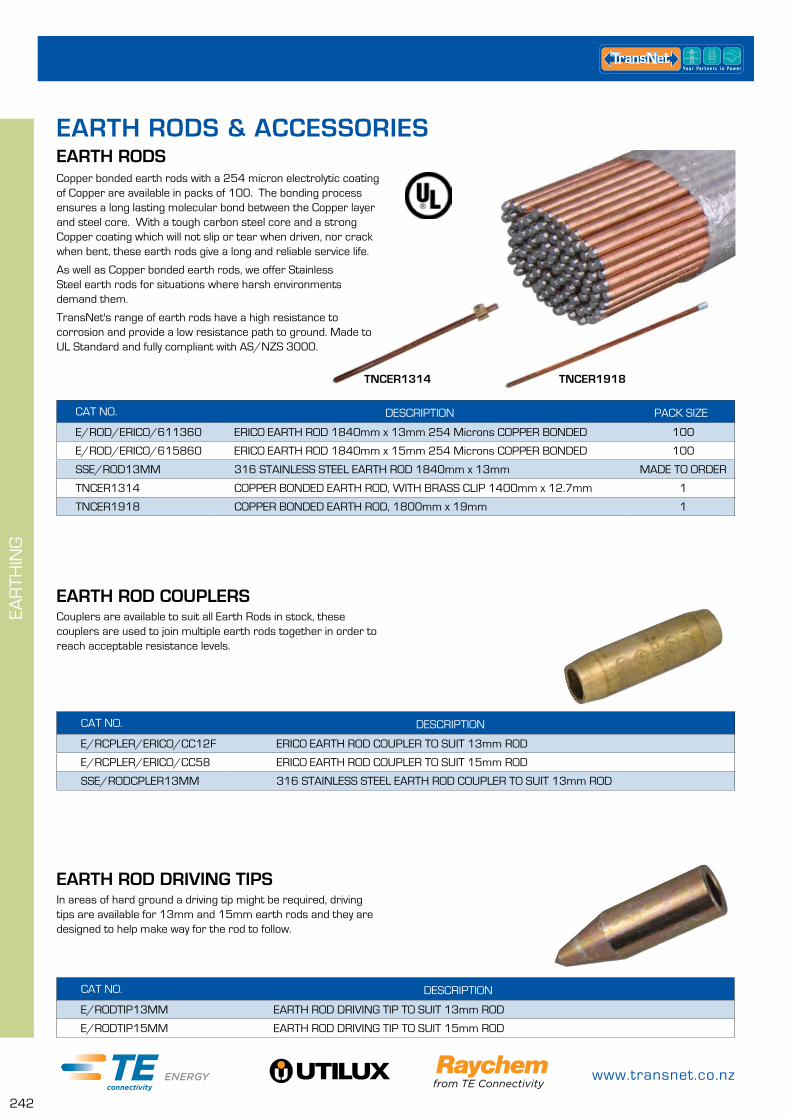
www.transnet.co.nz
242
EAR
THIN
G
CAT NO. DESCRIPTION
E/RODTIP13MM EARTH ROD DRIVING TIP TO SUIT 13mm ROD
E/RODTIP15MM EARTH ROD DRIVING TIP TO SUIT 15mm ROD
EARTH ROD DRIVING TIPSIn areas of hard ground a driving tip might be required, driving tips are available for 13mm and 15mm earth rods and they are designed to help make way for the rod to follow.
CAT NO. DESCRIPTION PACK SIZE
E/ROD/ERICO/611360 ERICO EARTH ROD 1840mm x 13mm 254 Microns COPPER BONDED 100
E/ROD/ERICO/615860 ERICO EARTH ROD 1840mm x 15mm 254 Microns COPPER BONDED 100
SSE/ROD13MM 316 STAINLESS STEEL EARTH ROD 1840mm x 13mm MADE TO ORDER
TNCER1314 COPPER BONDED EARTH ROD, WITH BRASS CLIP 1400mm x 12.7mm 1
TNCER1918 COPPER BONDED EARTH ROD, 1800mm x 19mm 1
EARTH RODSCopper bonded earth rods with a 254 micron electrolytic coating of Copper are available in packs of 100. The bonding process ensures a long lasting molecular bond between the Copper layer and steel core. With a tough carbon steel core and a strong Copper coating which will not slip or tear when driven, nor crack when bent, these earth rods give a long and reliable service life.
As well as Copper bonded earth rods, we offer Stainless Steel earth rods for situations where harsh environments demand them.
TransNet's range of earth rods have a high resistance to corrosion and provide a low resistance path to ground. Made to UL Standard and fully compliant with AS/NZS 3000.
CAT NO. DESCRIPTION
E/RCPLER/ERICO/CC12F ERICO EARTH ROD COUPLER TO SUIT 13mm ROD
E/RCPLER/ERICO/CC58 ERICO EARTH ROD COUPLER TO SUIT 15mm ROD
SSE/RODCPLER13MM 316 STAINLESS STEEL EARTH ROD COUPLER TO SUIT 13mm ROD
EARTH ROD COUPLERSCouplers are available to suit all Earth Rods in stock, these couplers are used to join multiple earth rods together in order to reach acceptable resistance levels.
TNCER1314 TNCER1918
EARTH RODS & ACCESSORIES
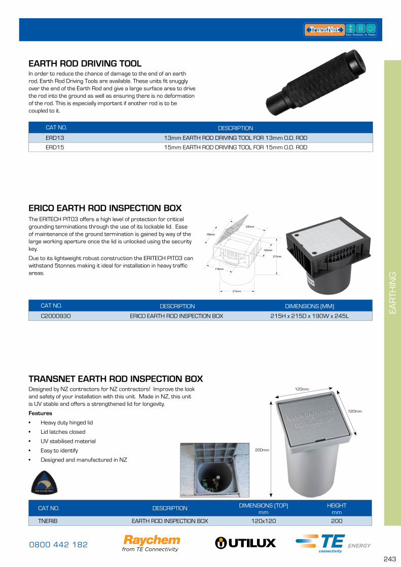
0800 442 182
243
EAR
THIN
G
EARTH ROD DRIVING TOOL
CAT NO. DESCRIPTION
ERD13 13mm EARTH ROD DRIVING TOOL FOR 13mm O.D. ROD
ERD15 15mm EARTH ROD DRIVING TOOL FOR 15mm O.D. ROD
In order to reduce the chance of damage to the end of an earth rod, Earth Rod Driving Tools are available. These units fit snuggly over the end of the Earth Rod and give a large surface area to drive the rod into the ground as well as ensuring there is no deformation of the rod. This is especially important if another rod is to be coupled to it.
CAT NO. DESCRIPTION DIMENSIONS (MM)
C2000930 ERICO EARTH ROD INSPECTION BOX 215H x 215D x 190W x 245L
ERICO EARTH ROD INSPECTION BOXThe ERITECH PIT03 offers a high level of protection for critical grounding terminations through the use of its lockable lid. Ease of maintenance of the ground termination is gained by way of the large working aperture once the lid is unlocked using the security key.
Due to its lightweight robust construction the ERITECH PIT03 can withstand 5tonnes making it ideal for installation in heavy traffic areas.
TRANSNET EARTH ROD INSPECTION BOX
CAT NO. DESCRIPTION DIMENSIONS (TOP) mm
HEIGHTmm
TNERIB EARTH ROD INSPECTION BOX 120x120 200
Designed by NZ contractors for NZ contractors! Improve the look and safety of your installation with this unit. Made in NZ, this unit is UV stable and offers a strengthened lid for longevity.
Features
• Heavy duty hinged lid
• Lid latches closed
• UV stabilised material
• Easy to identify
• Designed and manufactured in NZ
200mm
120mm
120mm
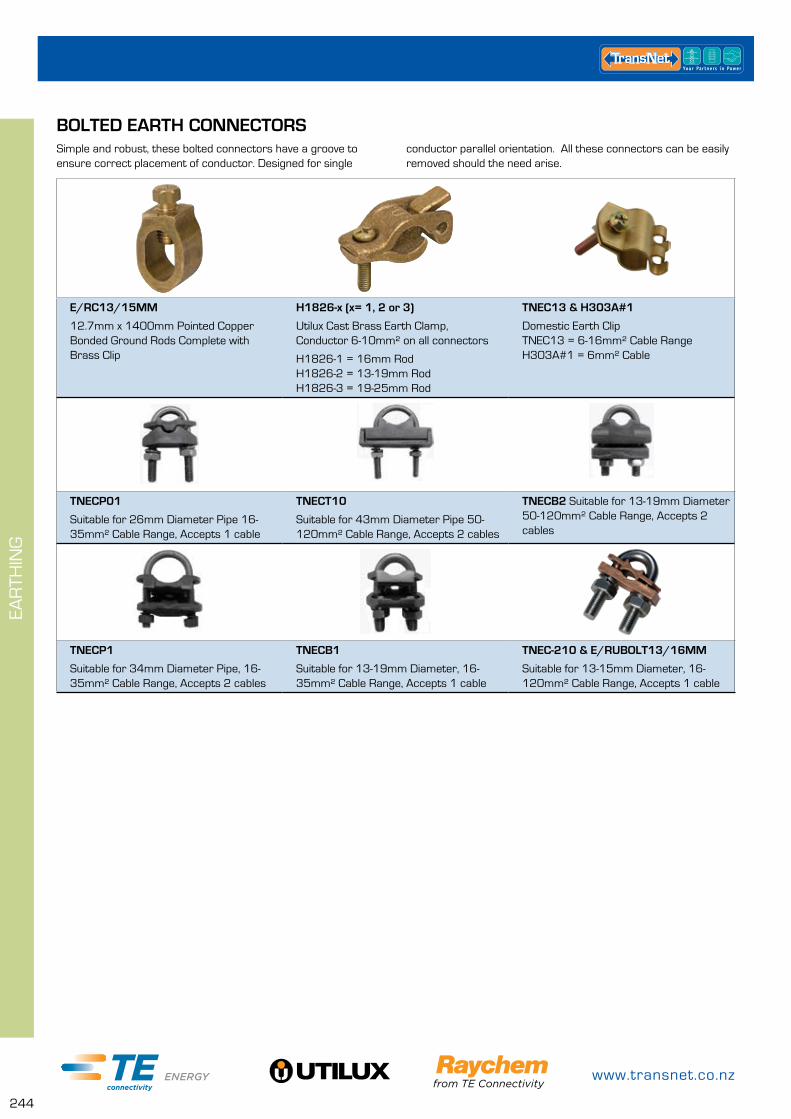
www.transnet.co.nz
244
EAR
THIN
G
E/RC13/15MM
12.7mm x 1400mm Pointed Copper Bonded Ground Rods Complete with Brass Clip
H1826-x (x= 1, 2 or 3)
Utilux Cast Brass Earth Clamp, Conductor 6-10mm² on all connectors
H1826-1 = 16mm Rod H1826-2 = 13-19mm Rod H1826-3 = 19-25mm Rod
TNEC13 & H303A#1
Domestic Earth Clip TNEC13 = 6-16mm² Cable Range H303A#1 = 6mm² Cable
TNECP01
Suitable for 26mm Diameter Pipe 16-35mm² Cable Range, Accepts 1 cable
TNECT10
Suitable for 43mm Diameter Pipe 50-120mm² Cable Range, Accepts 2 cables
TNECB2 Suitable for 13-19mm Diameter 50-120mm² Cable Range, Accepts 2 cables
TNECP1
Suitable for 34mm Diameter Pipe, 16-35mm² Cable Range, Accepts 2 cables
TNECB1
Suitable for 13-19mm Diameter, 16-35mm² Cable Range, Accepts 1 cable
TNEC-210 & E/RUBOLT13/16MM
Suitable for 13-15mm Diameter, 16-120mm² Cable Range, Accepts 1 cable
BOLTED EARTH CONNECTORSSimple and robust, these bolted connectors have a groove to ensure correct placement of conductor. Designed for single
conductor parallel orientation. All these connectors can be easily removed should the need arise.
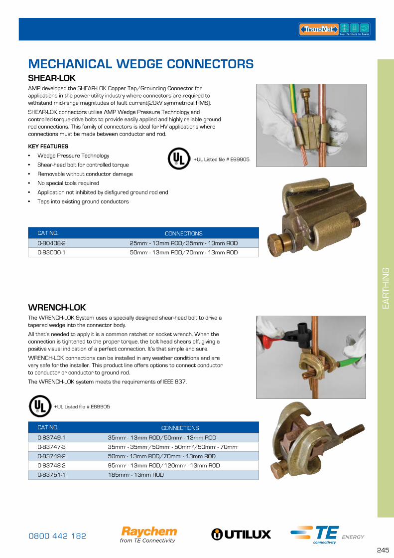
0800 442 182
245
EAR
THIN
G
CAT NO. CONNECTIONS
0-80408-2 25mm² - 13mm ROD/35mm² - 13mm ROD
0-83000-1 50mm² - 13mm ROD/70mm² - 13mm ROD
SHEAR-LOKMECHANICAL WEDGE CONNECTORS
WRENCH-LOK
AMP developed the SHEAR-LOK Copper Tap/Grounding Connector for applications in the power utility industry where connectors are required to withstand mid-range magnitudes of fault current(20kV symmetrical RMS).
SHEAR-LOK connectors utilise AMP Wedge Pressure Technology and controlled-torque-drive bolts to provide easily applied and highly reliable ground rod connections. This family of connectors is ideal for HV applications where connections must be made between conductor and rod.
+UL Listed file # E69905
+UL Listed file # E69905
KEY FEATURES
• Wedge Pressure Technology
• Shear-head bolt for controlled torque
• Removable without conductor damage
• No special tools required
• Application not inhibited by disfigured ground rod end
• Taps into existing ground conductors
The WRENCH-LOK System uses a specially designed shear-head bolt to drive a tapered wedge into the connector body.
All that’s needed to apply it is a common ratchet or socket wrench. When the connection is tightened to the proper torque, the bolt head shears off, giving a positive visual indication of a perfect connection. It’s that simple and sure.
WRENCH-LOK connections can be installed in any weather conditions and are very safe for the installer. This product line offers options to connect conductor to conductor or conductor to ground rod.
The WRENCH-LOK system meets the requirements of IEEE 837.
CAT NO. CONNECTIONS
0-83749-1 35mm² - 13mm ROD/50mm² - 13mm ROD
0-83747-3 35mm² - 35mm²/50mm² - 50mm²/50mm² - 70mm²
0-83749-2 50mm² - 13mm ROD/70mm² - 13mm ROD
0-83748-2 95mm² - 13mm ROD/120mm² - 13mm ROD
0-83751-1 185mm² - 13mm ROD
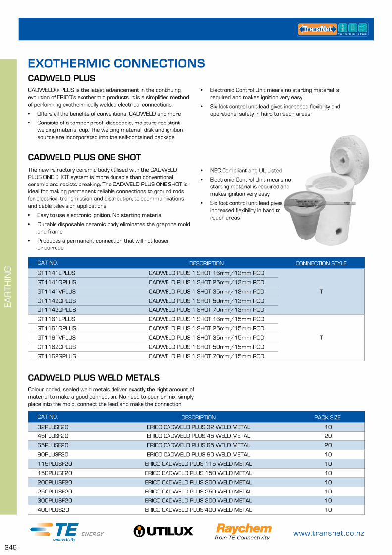
www.transnet.co.nz
246
EAR
THIN
G
CAT NO. DESCRIPTION PACK SIZE
32PLUSF20 ERICO CADWELD PLUS 32 WELD METAL 10
45PLUSF20 ERICO CADWELD PLUS 45 WELD METAL 20
65PLUSF20 ERICO CADWELD PLUS 65 WELD METAL 20
90PLUSF20 ERICO CADWELD PLUS 90 WELD METAL 10
115PLUSF20 ERICO CADWELD PLUS 115 WELD METAL 10
150PLUSF20 ERICO CADWELD PLUS 150 WELD METAL 10
200PLUSF20 ERICO CADWELD PLUS 200 WELD METAL 10
250PLUSF20 ERICO CADWELD PLUS 250 WELD METAL 10
300PLUSF20 ERICO CADWELD PLUS 300 WELD METAL 10
400PLUS20 ERICO CADWELD PLUS 400 WELD METAL 10
CADWELD PLUS
CADWELD PLUS WELD METALSColour coded, sealed weld metals deliver exactly the right amount of material to make a good connection. No need to pour or mix, simply place into the mold, connect the lead and make the connection.
CADWELD® PLUS is the latest advancement in the continuing evolution of ERICO’s exothermic products. It is a simplified method of performing exothermically welded electrical connections.
• Offers all the benefits of conventional CADWELD and more
• Consists of a tamper proof, disposable, moisture resistant welding material cup. The welding material, disk and ignition source are incorporated into the self-contained package
EXOTHERMIC CONNECTIONS
• Electronic Control Unit means no starting material is required and makes ignition very easy
• Six foot control unit lead gives increased flexibility and operational safety in hard to reach areas
CADWELD PLUS ONE SHOTThe new refractory ceramic body utilised with the CADWELD PLUS ONE SHOT system is more durable than conventional ceramic and resists breaking. The CADWELD PLUS ONE SHOT is ideal for making permanent reliable connections to ground rods for electrical transmission and distribution, telecommunications and cable television applications.
• Easy to use electronic ignition. No starting material
• Durable disposable ceramic body eliminates the graphite mold and frame
• Produces a permanent connection that will not loosen or corrode
CAT NO. DESCRIPTION CONNECTION STYLE
GT1141LPLUS CADWELD PLUS 1 SHOT 16mm²/13mm ROD
T
GT1141QPLUS CADWELD PLUS 1 SHOT 25mm²/13mm ROD
GT1141VPLUS CADWELD PLUS 1 SHOT 35mm²/13mm ROD
GT1142CPLUS CADWELD PLUS 1 SHOT 50mm²/13mm ROD
GT1142GPLUS CADWELD PLUS 1 SHOT 70mm²/13mm ROD
GT1161LPLUS CADWELD PLUS 1 SHOT 16mm²/15mm ROD
T
GT1161QPLUS CADWELD PLUS 1 SHOT 25mm²/15mm ROD
GT1161VPLUS CADWELD PLUS 1 SHOT 35mm²/15mm ROD
GT1162CPLUS CADWELD PLUS 1 SHOT 50mm²/15mm ROD
GT1162GPLUS CADWELD PLUS 1 SHOT 70mm²/15mm ROD
• NEC Compliant and UL Listed
• Electronic Control Unit means no starting material is required and makes ignition very easy
• Six foot control unit lead gives increased flexibility in hard to reach areas

0800 442 182
247
EAR
THIN
G
CADWELD PLUS MOLDSBecause the CADWELD® PLUS process uses a high temperature reaction of powdered Copper oxide and Aluminium the mold needs to withstand these high temperatures. In order to achieve this heat they are made of semi permanent graphite and should last for more than 50 welds if properly cared for and maintained. Many different connection styles are available for a variety of applications.
The table below shows the most common connection styles, if the connection you desire is not shown below please contact custom-er services for more information.
Above illustrates the most common connection types, there are many other types available. If there is a connection type you require but don’t see above, please contact our customer service team.
MOLD TYPE MOLD TYPE
GT – Tee/Horizontal cable, Vertical Rod
PT – Parallel thru/Horizon-tal, Over and under
TA – Tee/Horizontal XA – X/Horizontal, same plane
SS – Splice/Horizontal XB– X/Horizontal, lapped (uncut)
CONNECTION STYLE – Tee, Splice, Cross etc
SUBSTRATES TO BE CONNECTED – Cable to Rod, Cable to Cable etc
WHEN ORDERING YOUR CADWELD PLUS MOLD...Please have the following information at hand when ordering your CADWELD PLUS Mold.
MAIN OR RUN CONDUCTOR SIZE – 35mm², 95mm² etc
TAP CONDUCTOR OR ROD SIZE – 35mm², 13mm Rod etc
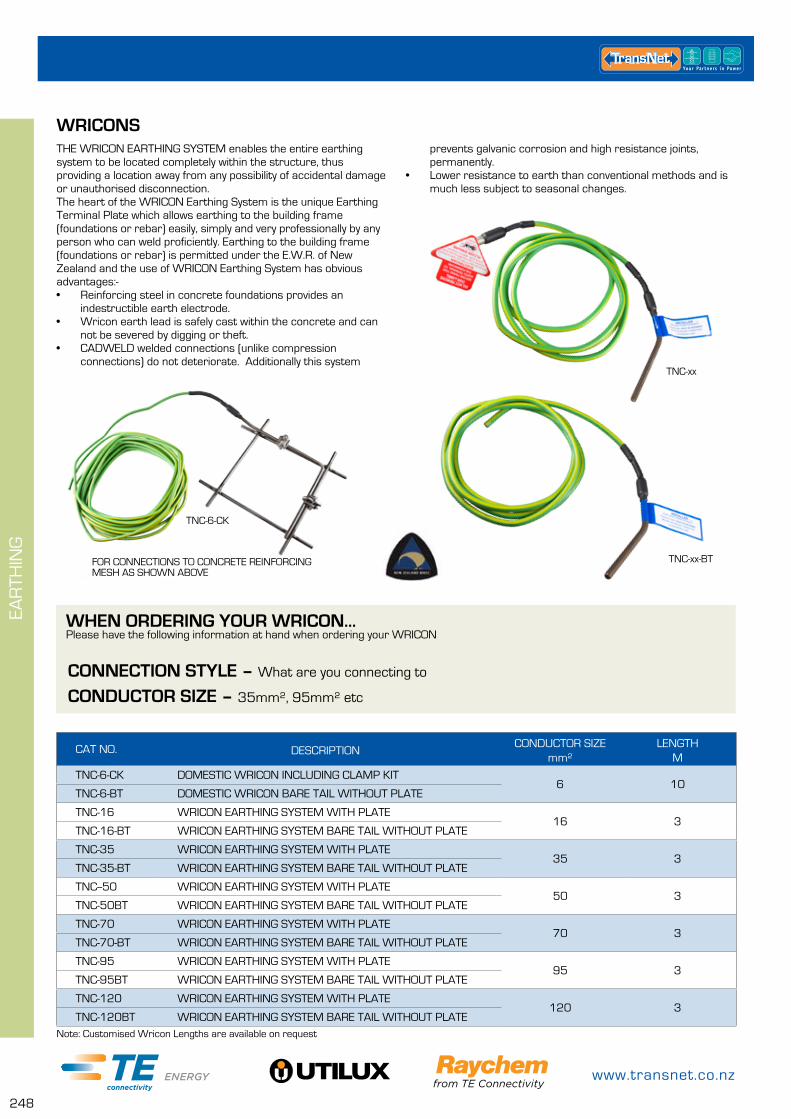
www.transnet.co.nz
248
EAR
THIN
G
WRICONSTHE WRICON EARTHING SYSTEM enables the entire earthing system to be located completely within the structure, thus providing a location away from any possibility of accidental damage or unauthorised disconnection.The heart of the WRICON Earthing System is the unique Earthing Terminal Plate which allows earthing to the building frame (foundations or rebar) easily, simply and very professionally by any person who can weld proficiently. Earthing to the building frame (foundations or rebar) is permitted under the E.W.R. of New Zealand and the use of WRICON Earthing System has obvious advantages:-• Reinforcing steel in concrete foundations provides an
indestructible earth electrode.• Wricon earth lead is safely cast within the concrete and can
not be severed by digging or theft.• CADWELD welded connections (unlike compression
connections) do not deteriorate. Additionally this system
CAT NO. DESCRIPTIONCONDUCTOR SIZE
mm²LENGTH
M
TNC-6-CK DOMESTIC WRICON INCLUDING CLAMP KIT6 10
TNC-6-BT DOMESTIC WRICON BARE TAIL WITHOUT PLATE
TNC-16 WRICON EARTHING SYSTEM WITH PLATE16 3
TNC-16-BT WRICON EARTHING SYSTEM BARE TAIL WITHOUT PLATE
TNC-35 WRICON EARTHING SYSTEM WITH PLATE35 3
TNC-35-BT WRICON EARTHING SYSTEM BARE TAIL WITHOUT PLATE
TNC--50 WRICON EARTHING SYSTEM WITH PLATE50 3
TNC-50BT WRICON EARTHING SYSTEM BARE TAIL WITHOUT PLATE
TNC-70 WRICON EARTHING SYSTEM WITH PLATE70 3
TNC-70-BT WRICON EARTHING SYSTEM BARE TAIL WITHOUT PLATE
TNC-95 WRICON EARTHING SYSTEM WITH PLATE95 3
TNC-95BT WRICON EARTHING SYSTEM BARE TAIL WITHOUT PLATE
TNC-120 WRICON EARTHING SYSTEM WITH PLATE120 3
TNC-120BT WRICON EARTHING SYSTEM BARE TAIL WITHOUT PLATE
TNC-xx-BT
TNC-xx
TNC-6-CK
CONNECTION STYLE – What are you connecting to
WHEN ORDERING YOUR WRICON...Please have the following information at hand when ordering your WRICON
CONDUCTOR SIZE – 35mm², 95mm² etc
FOR CONNECTIONS TO CONCRETE REINFORCING MESH AS SHOWN ABOVE
Note: Customised Wricon Lengths are available on request
prevents galvanic corrosion and high resistance joints, permanently.
• Lower resistance to earth than conventional methods and is much less subject to seasonal changes.

0800 442 182
249
EAR
THIN
G
CADWELD PLUS KITS
CAT NO. DESCRIPTION KIT CONTENTS
CADWELDPLUSKIT STARTER KIT CLEANING BRUSH, HANDLES, EARTH ROD DRIVING TOOL, CONTROL UNIT, TOOL BOX
CADWELDRENTAL RENTAL KIT CLEANING BRUSH, HANDLES, EARTH ROD DRIVING TOOL, CONTROL UNIT, TOOL BOX
MOLDRENTALKIT MOLD RENTAL MOLD, 10 WELD METALS (additional charge), CLEANING BRUSH, HANDLES, EARTH ROD DRIVING TOOL, CONTROL UNIT, TOOL BOX
There are three kits available, we have a starter kit for people who want to purchase everything they need to make off Cadweld connections (CADWELDPLUSKIT), a rental kit without a mold, this gives you the option to purchase your very own mold and just rent the rest of the gear (CADWELDRENTAL), or the full rental kit which includes the mold specific to the requirements of the job (MOLDRENTALKIT), this last kit is perfect if you only have a small number of connections to make.
All kits listed below include:
• Mold Cleaning Brush
• Mold Sealing Putty
• Cadweld Plus Control Unit
• Mold Handles – L160
• Earth Rod Driving Tool
There is enough room to store a number of weld metals and some protective gloves and glasses in the tool box.
CAT NO. DESCRIPTION MOLD TYPE
L160 CADWELD PLUS MOLD HANDLES C, R
L159 CADWELD PLUS MOLD HANDLES D, F
MOLD HANDLESFor most lug, cable or rectangular bus connections, handle clamps are used. These handle clamps are available in two sizes and between them fit many different sizes and types of molds. To secure them in place simply tighten the positioning screws.
MOLD CLEANING BRUSH
CAT NO. DESCRIPTION
T310 MOLD CLEANING BRUSH
This soft bristle brush is used to clean the graphite mold without causing damage or undue wear to it.
Note: Rental kits are rented by the day only.
For Rental Kit with Mold order form, please see the end of this section.
CADWELD PLUS ACCESSORIES
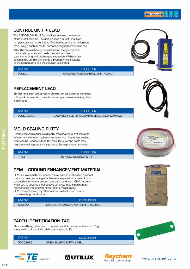
www.transnet.co.nz
250
EAR
THIN
G
CAT NO. DESCRIPTION
PLUSCU CADWELD PLUS CONTROL UNIT + LEAD
CONTROL UNIT + LEADThe CADWELD® PLUS Control Unit initiates the reaction of the metal crucible. The unit includes a 6 foot long, high temperature, control unit lead. The lead attaches to the ignition strip using a custom made, purpose-designed termination clip.
After the termination clip is installed on the ignition strip, the installer pushes and holds the ignition button to start a charging and discharging sequence. Within a few seconds the control unit sends a predetermined voltage to the ignition strip and the reaction is initiated.
REPLACEMENT LEAD
CAT NO. DESCRIPTION
PLUSCULDQC CADWELD PLUS REPLACEMENT LEAD, QUICK CONNECT
Six foot long, high temperature control unit lead, comes complete with quick connect terminals for easy replacement if existing lead is damaged.
CAT NO. DESCRIPTION
T403 1lb MOLD SEALING PUTTY
MOLD SEALING PUTTYUsed to prevent molten weld metal from leaking out of the mold. When the cable opening becomes worn from heavy use, sealing putty can be used to extend the mold life. 7 strand cable also requires sealing putty as it is prone to leakage around strands.
GEM – GROUND ENHANCEMENT MATERIAL
CAT NO. DESCRIPTION
GEM25A GROUND ENHANCING MATERIAL, 25LB BAG
GEM is a low-resistance, noncorrosive, carbon dust-based material that improves grounding effectiveness, especially in areas of poor conductivity or where ground rods can’t be driven. GEM hardens when set, to become a conductive concrete that is permanent, maintenance-free and will never leach or wash away.GEM does not adversely affect soil and will not leach ions or contaminate ground water.
EARTH IDENTIFICATION TAG
CAT NO. DESCRIPTION
55002936 GREEN PLASTIC EARTH LABEL
Plastic earth tag, attaches to the main earth for easy identification. Tag is easy to install and UV stabilised for a longer life.

0800 442 182
251
EAR
THIN
G
1. Tick a box to identify the mold size you require2. Enter number of connections to be made (10 weld metals
will be charged for & supplied with each rental)3. Complete the customer details4. Complete the end user details5. Fax or email to TransNet
Additional costs will be incurred if goods are damaged
5. FAX OR EMAIL THIS FORM – 0800 442 183. +649 274 5490, [email protected]
*RETURN MOLD KIT TO – CONTRACT CONNECTIONS, 20 Kerwyn Ave, East Tamaki
FOR ASSISTANCE CALL TRANSNET ON 0800 442 182 OR +649 274 3340
CADWELD MOLD RENTAL
Company: Contact Person:
Contact No: Date Required:
Delivery Address (Customer Can Collect):
Estimated Rental Days (No Half Days):
4. END USER/CONTRACTOR DETAILS
CONTRACT CONNECTIONS LTD USE ONLYShip Date:
Actual Return Date:
Total Number of Days Hire:
Return Condition of Goods:
Entered By:
TRANSNET PURCHASING USE ONLYPurchase Order No:
Requested By:
Date:
Company: Contact Person:
Contact No: Order No: Date:
3. CUSTOMER/WHOLESALER DETAILS
2. NUMBER OF CONNECTIONSNOTE: Minimum of 10 connections catered for in each rental
QTY
NOTE: All rental molds are for GT type connection style, Kit contains all parts required to make 10 connections
Hire Molds for 13mm Ground Rods Hire Molds for 15mm Ground Rods
35mm² 35mm²
50mm² 50mm²
70mm² 70mm²
95mm² 95mm²
120mm² 120mm²
1. CONNECTION SELECTION
Rental Molds offer GT Style Connection Only (cable to ground rod)
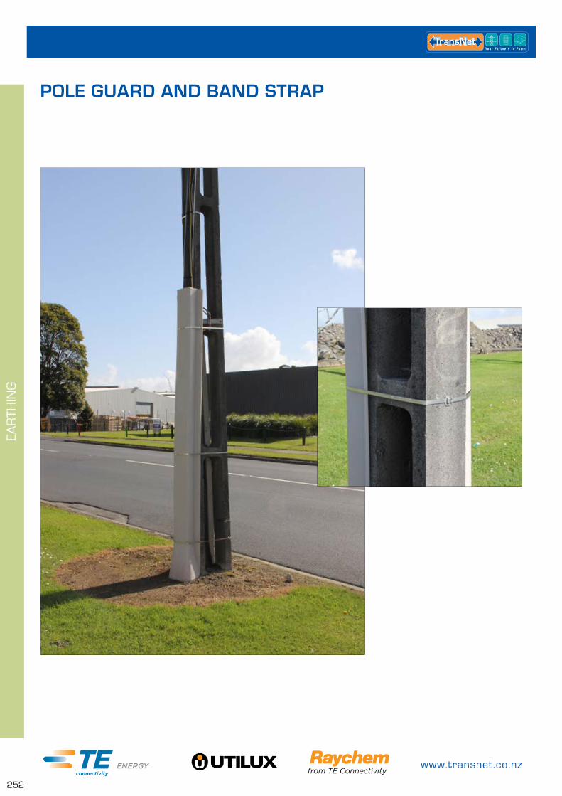
www.transnet.co.nz
252
EAR
THIN
G
POLE GUARD AND BAND STRAP
0800 442 182
253
CA
BLE
MA
NA
GEM
ENT
& P
RO
TEC
TIO
N
TAPE PAGE
Self Amalgamating Tape 254
Denso 254
Insulation Tape 254
CABLE PULLING LUBRICANTS PAGE
Techlube 255
Techlube Heavy Duty 255
Techlube Heavy Duty Pre-lube 255
Techlube PHD 255
CLEANING LUBRICANTS PAGE
Cleaning Solvent - 1ltr bottle 256
Cleaning Solvent Wipes 256
Fibre Optic Cable Solvent Wipes 256
Anti-bacterial Hand Cleaning Wipes 256
LUBRICANT SPRAY PAGE
CRC 5.56 – General Purpose Lubrication Spray 257
CRC 2.26 – Advanced Lubrication Spray 257
CRC 808 – Silicone Spray 257
Rem Oil – AMPACT Tool Cleaning 257
CABLE PROTECTION PAGE
Cable Cover 258
Warning Strip 259
Pole Guards 259
Guy Guard 260
CABLE CLAMPS PAGE
Universal Cable Clamps – UKR 90 260
Single Conductor Clamps 261
Trefoil Conductor Clamps 262
Neoprene Insert 262
CABLE BUNDLING PAGE
Nylon Cable Ties 263
Stainless Steel Cable Ties 264
Stainless Steel Band Strap & Buckles 264
IDENTIFICATION & LABELLING PAGE
Critchley K65 Markers 265
Everlast 1" Pole Markers 266
Everlast Phase Markers 267
Do Not Climb Tags 267
CABLE MANAGEMENT & PROTECTION
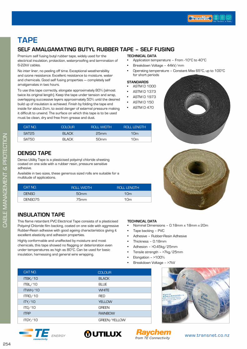
www.transnet.co.nz
254
STANDARDS• ASTM D 1000
• ASTM D 1373
• ASTM D 1973
• ASTM D 150
• ASTM D 470
TECHNICAL DATA• Application temperature – From -10°C to 40°C
• Breakdown Voltage – 44kV/mm
• Operating temperature – Constant Max 65°C, up to 100°C for short periods
SELF AMALGAMATING BUTYL RUBBER TAPE – SELF FUSINGPremium self fusing butyl rubber tape, widely used for the electrical insulation, protection, waterproofing and termination of 6-22kV cables.
No inter liner, no peeling off time. Exceptional weatherability and ozone resistance. Excellent resistance to moisture, water and chemicals. Good self fusing properties — completely self amalgamates in two hours.
To use this tape correctly, elongate approximately 80% (almost twice its original length). Keep the tape under tension and wrap, overlapping successive layers approximately 50% until the desired build up of insulation is achieved. Finish by folding the tape end inside for about 2cm, to avoid danger of external pressure making it difficult to unwind. The surface on which this tape is to be used must be clean, dry and free from grease and dust.
CAT NO. COLOUR ROLL WIDTH ROLL LENGTH
SAT25 BLACK 25mm 10m
SAT50 BLACK 50mm 10m
CAT NO. COLOUR
ITBK/10 BLACK
ITBL/10 BLUE
ITWH/10 WHITE
ITRD/10 RED
ITY/10 YELLOW
ITG/10 GREEN
ITRP RAINBOW
ITGY/10 GREEN/YELLOW
CAT NO. ROLL WIDTH ROLL LENGTH
DENSO 50mm 10m
DENSO75 75mm 10m
INSULATION TAPE
DENSO TAPE
TECHNICAL DATA• Nominal Dimensions – 0.18mm x 18mm x 20m
• Tape backing – PVC
• Adhesive – Rubber-Resin Adhesive
• Thickness – 0.18mm
• Adhesion – >0.45kg/25mm
• Tensile strength – >7kg/25mm
• Elongation – >100%
• Breakdown Voltage – >7kV
This flame retardant PVC Electrical Tape consists of a plasticised Polyvinyl Chloride film backing, coated on one side with aggressive Rubber-Resin adhesive with good ageing characteristics giving it excellent elasticity and adhesion properties.
Highly conformable and unaffected by moisture and most chemicals, this tape showed no flagging or deterioration even under temperatures as high as 80°C. Can be used for basic insulation, harnessing and general wire wrapping.
Denso Utility Tape is a plasticised polyvinyl chloride sheeting coated on one side with a rubber resin, pressure sensitive adhesive.
Available in two sizes, these generous sized rolls are suitable for a multitude of applications.
CA
BLE
MA
NA
GEM
ENT
& P
RO
TEC
TIO
N
TAPE
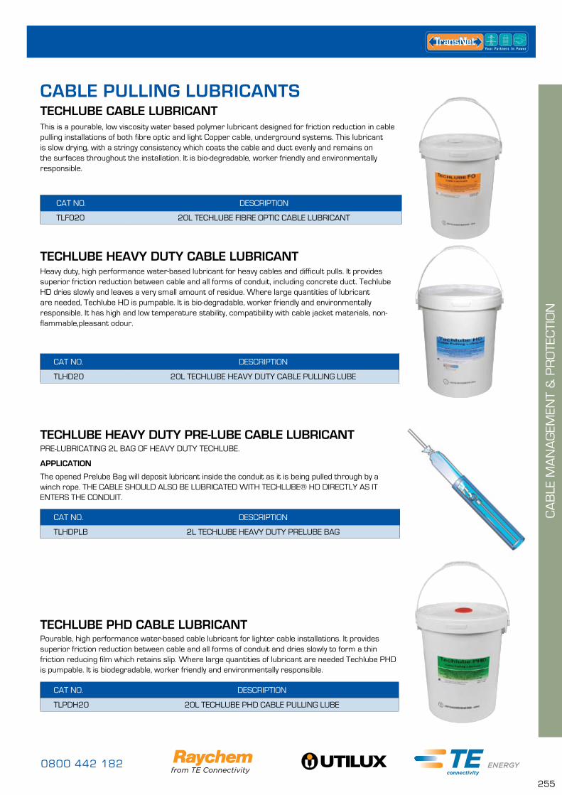
0800 442 182
255
TECHLUBE PHD CABLE LUBRICANTPourable, high performance water-based cable lubricant for lighter cable installations. It provides superior friction reduction between cable and all forms of conduit and dries slowly to form a thin friction reducing film which retains slip. Where large quantities of lubricant are needed Techlube PHD is pumpable. It is biodegradable, worker friendly and environmentally responsible.
CAT NO. DESCRIPTION
TLPDH20 20L TECHLUBE PHD CABLE PULLING LUBE
TECHLUBE CABLE LUBRICANTThis is a pourable, low viscosity water based polymer lubricant designed for friction reduction in cable pulling installations of both fibre optic and light Copper cable, underground systems. This lubricant is slow drying, with a stringy consistency which coats the cable and duct evenly and remains on the surfaces throughout the installation. It is bio-degradable, worker friendly and environmentally responsible.
CAT NO. DESCRIPTION
TLF020 20L TECHLUBE FIBRE OPTIC CABLE LUBRICANT
Heavy duty, high performance water-based lubricant for heavy cables and difficult pulls. It provides superior friction reduction between cable and all forms of conduit, including concrete duct. Techlube HD dries slowly and leaves a very small amount of residue. Where large quantities of lubricant are needed, Techlube HD is pumpable. It is bio-degradable, worker friendly and environmentally responsible. It has high and low temperature stability, compatibility with cable jacket materials, non-flammable,pleasant odour.
CAT NO. DESCRIPTION
TLHD20 20L TECHLUBE HEAVY DUTY CABLE PULLING LUBE
TECHLUBE HEAVY DUTY CABLE LUBRICANT
TECHLUBE HEAVY DUTY PRE-LUBE CABLE LUBRICANT
CAT NO. DESCRIPTION
TLHDPLB 2L TECHLUBE HEAVY DUTY PRELUBE BAG
APPLICATION
The opened Prelube Bag will deposit lubricant inside the conduit as it is being pulled through by a winch rope. THE CABLE SHOULD ALSO BE LUBRICATED WITH TECHLUBE® HD DIRECTLY AS IT ENTERS THE CONDUIT.
PRE-LUBRICATING 2L BAG OF HEAVY DUTY TECHLUBE.
CA
BLE
MA
NA
GEM
ENT
& P
RO
TEC
TIO
N
CABLE PULLING LUBRICANTS

www.transnet.co.nz
256
Solvent for surface preparation of bonding area. It cleans tools and equipment including motors, conductors, switchgear and generators and is fully compatible with all components. PF solvent is user friendly, environmentally responsible, 100% stable and non-ozone depleting.
CAT NO. DESCRIPTION
PF1LTR PF CLEANING SOLVENT 1LTR BOTTLE
CLEANING SOLVENT
CAT NO. DESCRIPTION
PF250 PF CLEANING SOLVENT WIPES (250PK)
CLEANING SOLVENT WIPESSolvent wipes for surface preparation of bonding area. It cleans tools and equipment including motors, conductors, switchgear and generators leaving no residue or fibres and is fully compatible with all components. PF solvent is user friendly, environmentally responsible, 100% stable and non-ozone depleting.
CAT NO. DESCRIPTION
DGELBW150 SOLVENT BUCKET (150) WIPES – FIBRE
FIBRE OPTIC CLEANING SOLVENT WIPESd’Gel is a high performance cleaner of cables, tools and equipment. It was specifically developed for the safe and easy removal of petroleum, polyethylene and silicone based gels from filled Copper and fibre optic communication cables.
d’Gel wipes remove oils, soils, gels and cable blocking compounds without removing ID inks or leaving residue and fibres. It is alcohol and halogen free, low odour, non toxic, equally effective with copper and fibre cables, 100% stable, environmentally responsible, non-ozone depleting and user friendly.
CAT NO. DESCRIPTION
PFANTIBAC ANTI-BAC HAND CLEANING WIPES x 100
ANTI-BACTERIAL HAND CLEANING WIPESHeavy duty antibacterial hand cleaning wipes allow safe and effective waterless hand cleaning in the field. Removes oils, greases, combustion and tar residues.
Tested and proven against Weil’s Disease and E-Coli. Anti Bac is a double-sided smooth/abrasive wipe with a highly effective foaming cleaning solution. Contains skin rehydrant to prevent dryness.
CA
BLE
MA
NA
GEM
ENT
& P
RO
TEC
TIO
N
CLEANING LUBRICANTS
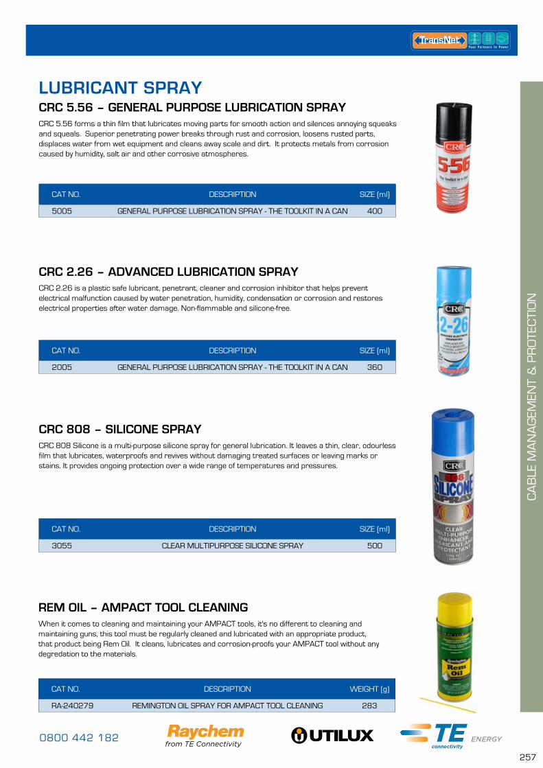
0800 442 182
257
CRC 5.56 forms a thin film that lubricates moving parts for smooth action and silences annoying squeaks and squeals. Superior penetrating power breaks through rust and corrosion, loosens rusted parts, displaces water from wet equipment and cleans away scale and dirt. It protects metals from corrosion caused by humidity, salt air and other corrosive atmospheres.
CRC 2.26 is a plastic safe lubricant, penetrant, cleaner and corrosion inhibitor that helps prevent electrical malfunction caused by water penetration, humidity, condensation or corrosion and restores electrical properties after water damage. Non-flammable and silicone-free.
CRC 808 Silicone is a multi-purpose silicone spray for general lubrication. It leaves a thin, clear, odourless film that lubricates, waterproofs and revives without damaging treated surfaces or leaving marks or stains. It provides ongoing protection over a wide range of temperatures and pressures.
CAT NO. DESCRIPTION SIZE (ml)
5005 GENERAL PURPOSE LUBRICATION SPRAY - THE TOOLKIT IN A CAN 400
CAT NO. DESCRIPTION SIZE (ml)
2005 GENERAL PURPOSE LUBRICATION SPRAY - THE TOOLKIT IN A CAN 360
CAT NO. DESCRIPTION SIZE (ml)
3055 CLEAR MULTIPURPOSE SILICONE SPRAY 500
CA
BLE
MA
NA
GEM
ENT
& P
RO
TEC
TIO
N
CRC 5.56 – GENERAL PURPOSE LUBRICATION SPRAY
CRC 2.26 – ADVANCED LUBRICATION SPRAY
CRC 808 – SILICONE SPRAY
LUBRICANT SPRAY
When it comes to cleaning and maintaining your AMPACT tools, it's no different to cleaning and maintaining guns, this tool must be regularly cleaned and lubricated with an appropriate product, that product being Rem Oil. It cleans, lubricates and corrosion-proofs your AMPACT tool without any degredation to the materials.
CAT NO. DESCRIPTION WEIGHT (g)
RA-240279 REMINGTON OIL SPRAY FOR AMPACT TOOL CLEANING 283
REM OIL – AMPACT TOOL CLEANING
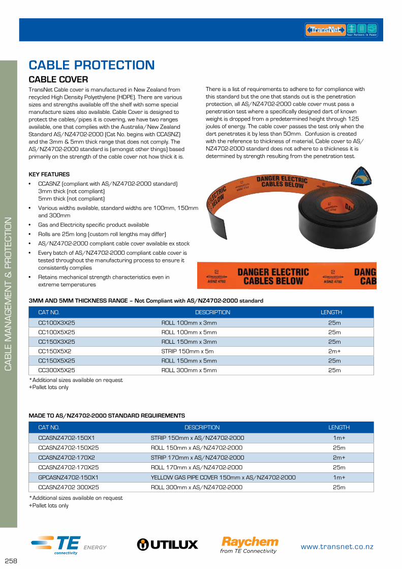
www.transnet.co.nz
258
CAT NO. DESCRIPTION LENGTH
CC100X3X25 ROLL 100mm x 3mm 25m
CC100X5X25 ROLL 100mm x 5mm 25m
CC150X3X25 ROLL 150mm x 3mm 25m
CC150X5X2 STRIP 150mm x 5m 2m+
CC150X5X25 ROLL 150mm x 5mm 25m
CC300X5X25 ROLL 300mm x 5mm 25m
CAT NO. DESCRIPTION LENGTH
CCASNZ4702-150X1 STRIP 150mm x AS/NZ4702-2000 1m+
CCASNZ4702-150X25 ROLL 150mm x AS/NZ4702-2000 25m
CCASNZ4702-170X2 STRIP 170mm x AS/NZ4702-2000 2m+
CCASNZ4702-170X25 ROLL 170mm x AS/NZ4702-2000 25m
GPCASNZ4702-150X1 YELLOW GAS PIPE COVER 150mm x AS/NZ4702-2000 1m+
CCASNZ4702 300X25 ROLL 300mm x AS/NZ4702-2000 25m
TransNet Cable cover is manufactured in New Zealand from recycled High Density Polyethylene (HDPE). There are various sizes and strengths available off the shelf with some special manufacture sizes also available. Cable Cover is designed to protect the cables/pipes it is covering, we have two ranges available, one that complies with the Australia/New Zealand Standard AS/NZ4702-2000 (Cat No. begins with CCASNZ) and the 3mm & 5mm thick range that does not comply. The AS/NZ4702-2000 standard is (amongst other things) based primarily on the strength of the cable cover not how thick it is.
KEY FEATURES
• CCASNZ (compliant with AS/NZ4702-2000 standard) 3mm thick (not compliant) 5mm thick (not compliant)
• Various widths available, standard widths are 100mm, 150mm and 300mm
• Gas and Electricity specific product available
• Rolls are 25m long (custom roll lengths may differ)
• AS/NZ4702-2000 compliant cable cover available ex stock
• Every batch of AS/NZ4702-2000 compliant cable cover is tested throughout the manufacturing process to ensure it consistently complies
• Retains mechanical strength characteristics even in extreme temperatures
*Additional sizes available on request+Pallet lots only
+Pallet lots only*Additional sizes available on request
MADE TO AS/NZ4702-2000 STANDARD REQUIREMENTS
CABLE COVERThere is a list of requirements to adhere to for compliance with this standard but the one that stands out is the penetration protection, all AS/NZ4702-2000 cable cover must pass a penetration test where a specifically designed dart of known weight is dropped from a predetermined height through 125 joules of energy. The cable cover passes the test only when the dart penetrates it by less than 50mm. Confusion is created with the reference to thickness of material, Cable cover to AS/NZ4702-2000 standard does not adhere to a thickness it is determined by strength resulting from the penetration test.
3MM AND 5MM THICKNESS RANGE – Not Compliant with AS/NZ4702-2000 standard
CABLE PROTECTION
CA
BLE
MA
NA
GEM
ENT
& P
RO
TEC
TIO
N
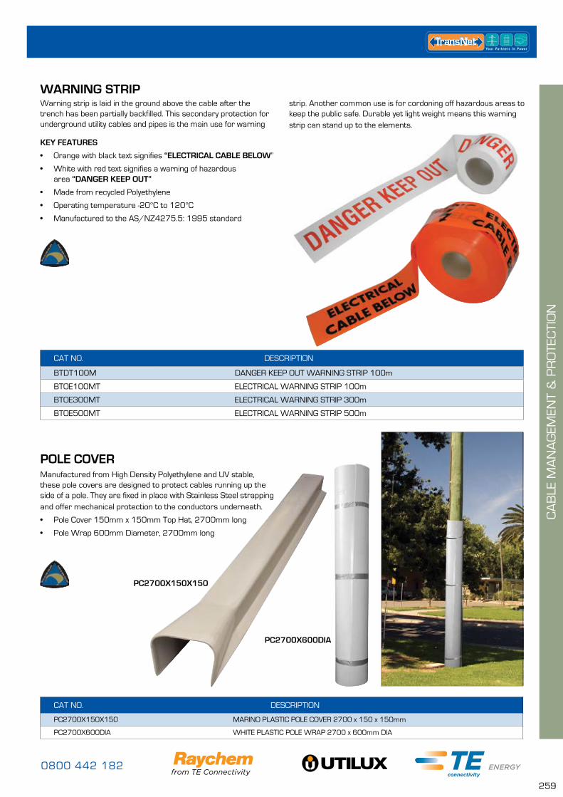
0800 442 182
259
CAT NO. DESCRIPTION
BTDT100M DANGER KEEP OUT WARNING STRIP 100m
BTOE100MT ELECTRICAL WARNING STRIP 100m
BTOE300MT ELECTRICAL WARNING STRIP 300m
BTOE500MT ELECTRICAL WARNING STRIP 500m
Warning strip is laid in the ground above the cable after the trench has been partially backfilled. This secondary protection for underground utility cables and pipes is the main use for warning
KEY FEATURES
• Orange with black text signifies “ELECTRICAL CABLE BELOW”
• White with red text signifies a warning of hazardous area “DANGER KEEP OUT”
• Made from recycled Polyethylene
• Operating temperature -20°C to 120°C
• Manufactured to the AS/NZ4275.5: 1995 standard
WARNING STRIPstrip. Another common use is for cordoning off hazardous areas to keep the public safe. Durable yet light weight means this warning strip can stand up to the elements.
POLE COVERManufactured from High Density Polyethylene and UV stable, these pole covers are designed to protect cables running up the side of a pole. They are fixed in place with Stainless Steel strapping and offer mechanical protection to the conductors underneath.
• Pole Cover 150mm x 150mm Top Hat, 2700mm long
• Pole Wrap 600mm Diameter, 2700mm long
CAT NO. DESCRIPTION
PC2700X150X150 MARINO PLASTIC POLE COVER 2700 x 150 x 150mm
PC2700X600DIA WHITE PLASTIC POLE WRAP 2700 x 600mm DIA
PC2700X150X150
PC2700X600DIA
CA
BLE
MA
NA
GEM
ENT
& P
RO
TEC
TIO
N
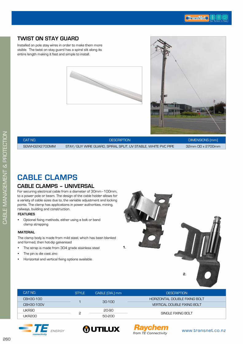
www.transnet.co.nz
260
TWIST ON STAY GUARDInstalled on pole stay wires in order to make them more visible. The twist on stay guard has a spiral slit along its entire length making it fast and simple to install.
CAT NO. DESCRIPTION DIMENSIONS (mm)
SGWH32X2700MM STAY/GUY WIRE GUARD, SPIRAL SPLIT, UV STABLE, WHITE PVC PIPE 32mm OD x 2700mm
CABLE CLAMPS
FEATURES
• Optional fixing methods, either using a bolt or band clamp strapping
MATERIAL
The clamp body is made from mild steel, which has been blanked and formed, then hot-dip galvanised
• The strap is made from 304 grade stainless steel
• The pin is die cast zinc
• Horizontal and vertical fixing options available
CAT NO. STYLE CABLE (DIA.) mm DESCRIPTION
CBH30-1001 30-100
HORIZONTAL DOUBLE FIXING BOLT
CBH30-100V VERTICAL DOUBLE FIXING BOLT
UKR902
20-90SINGLE FIXING BOLT
UKR200 50-200
CABLE CLAMPS – UNIVERSALFor securing electrical cable from a diameter of 30mm–100mm, to a power pole or beam. The design of the cable holder allows for a variety of cable sizes due to, the variable adjustment and locking points. The clamp has applications in power authorities, mining, railways, building and construction.
1.
2.
CA
BLE
MA
NA
GEM
ENT
& P
RO
TEC
TIO
N
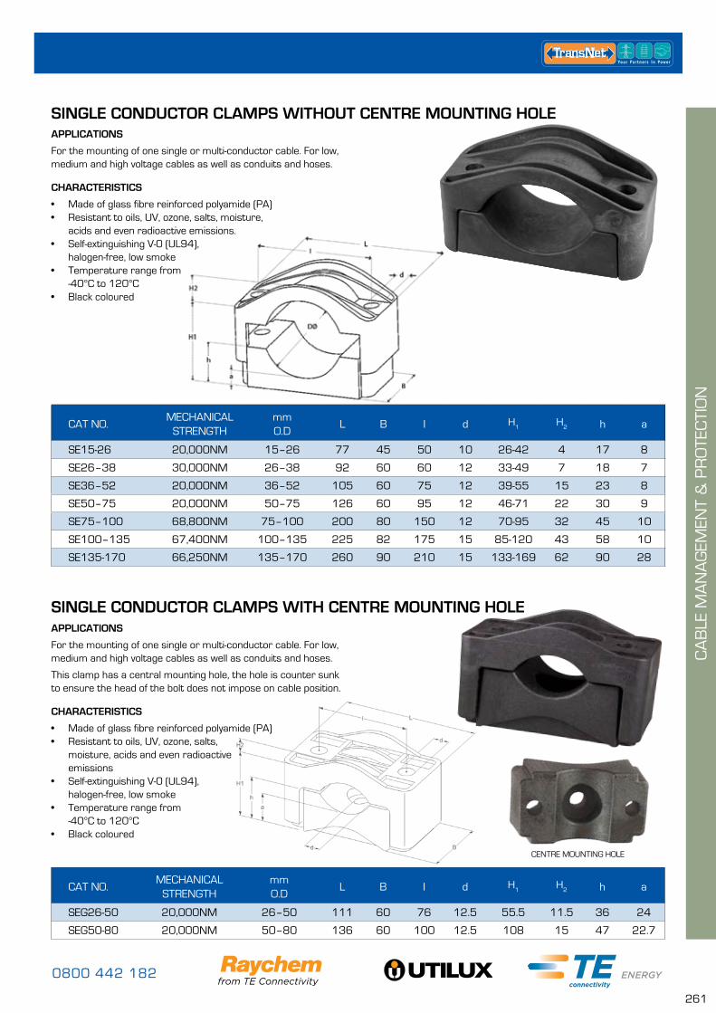
0800 442 182
261
SINGLE CONDUCTOR CLAMPS WITH CENTRE MOUNTING HOLEAPPLICATIONS
For the mounting of one single or multi-conductor cable. For low, medium and high voltage cables as well as conduits and hoses.
This clamp has a central mounting hole, the hole is counter sunk to ensure the head of the bolt does not impose on cable position.
CHARACTERISTICS
• Made of glass fibre reinforced polyamide (PA)• Resistant to oils, UV, ozone, salts,
moisture, acids and even radioactive emissions
• Self-extinguishing V-0 (UL94), halogen-free, low smoke
• Temperature range from -40°C to 120°C
• Black coloured
CAT NO.MECHANICAL
STRENGTHmm O.D
L B I d H1
H2 h a
SEG26-50 20,000NM 26–50 111 60 76 12.5 55.5 11.5 36 24
SEG50-80 20,000NM 50–80 136 60 100 12.5 108 15 47 22.7
CENTRE MOUNTING HOLE
SINGLE CONDUCTOR CLAMPS WITHOUT CENTRE MOUNTING HOLEAPPLICATIONS
For the mounting of one single or multi-conductor cable. For low, medium and high voltage cables as well as conduits and hoses.
CHARACTERISTICS
• Made of glass fibre reinforced polyamide (PA)• Resistant to oils, UV, ozone, salts, moisture,
acids and even radioactive emissions.• Self-extinguishing V-0 (UL94),
halogen-free, low smoke• Temperature range from
-40°C to 120°C• Black coloured
CAT NO.MECHANICAL
STRENGTHmm O.D
L B I d H1
H2 h a
SE15-26 20,000NM 15–26 77 45 50 10 26-42 4 17 8
SE26–38 30,000NM 26–38 92 60 60 12 33-49 7 18 7
SE36–52 20,000NM 36–52 105 60 75 12 39-55 15 23 8
SE50–75 20,000NM 50–75 126 60 95 12 46-71 22 30 9
SE75–100 68,800NM 75–100 200 80 150 12 70-95 32 45 10
SE100–135 67,400NM 100–135 225 82 175 15 85-120 43 58 10
SE135-170 66,250NM 135–170 260 90 210 15 133-169 62 90 28
CA
BLE
MA
NA
GEM
ENT
& P
RO
TEC
TIO
N
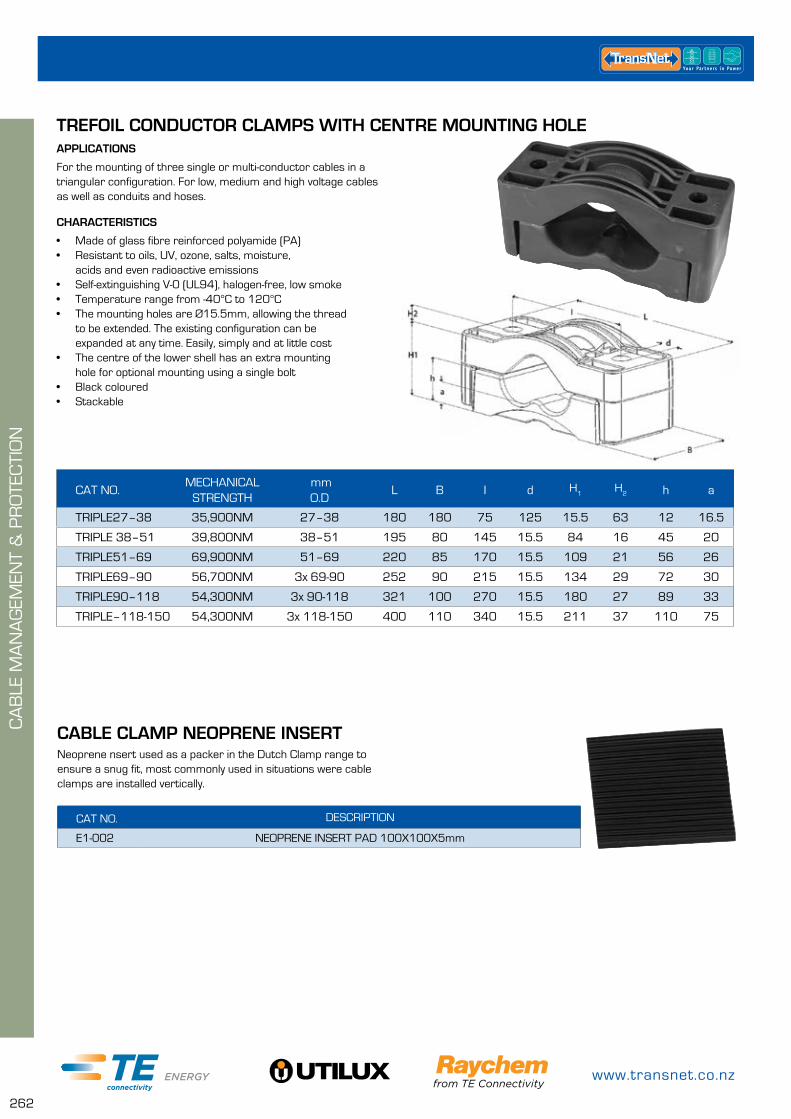
www.transnet.co.nz
262
APPLICATIONS
For the mounting of three single or multi-conductor cables in a triangular configuration. For low, medium and high voltage cables as well as conduits and hoses.
CHARACTERISTICS
• Made of glass fibre reinforced polyamide (PA)• Resistant to oils, UV, ozone, salts, moisture,
acids and even radioactive emissions• Self-extinguishing V-0 (UL94), halogen-free, low smoke• Temperature range from -40°C to 120°C• The mounting holes are Ø15.5mm, allowing the thread
to be extended. The existing configuration can be expanded at any time. Easily, simply and at little cost
• The centre of the lower shell has an extra mounting hole for optional mounting using a single bolt
• Black coloured• Stackable
CAT NO.MECHANICAL
STRENGTH mm O.D
L B I d H1
H2 h a
TRIPLE27–38 35,900NM 27–38 180 180 75 125 15.5 63 12 16.5
TRIPLE 38–51 39,800NM 38–51 195 80 145 15.5 84 16 45 20
TRIPLE51–69 69,900NM 51–69 220 85 170 15.5 109 21 56 26
TRIPLE69–90 56,700NM 3x 69-90 252 90 215 15.5 134 29 72 30
TRIPLE90–118 54,300NM 3x 90-118 321 100 270 15.5 180 27 89 33
TRIPLE–118-150 54,300NM 3x 118-150 400 110 340 15.5 211 37 110 75
TREFOIL CONDUCTOR CLAMPS WITH CENTRE MOUNTING HOLE
CA
BLE
MA
NA
GEM
ENT
& P
RO
TEC
TIO
N
Neoprene nsert used as a packer in the Dutch Clamp range to ensure a snug fit, most commonly used in situations were cable clamps are installed vertically.
CAT NO. DESCRIPTION
E1-002 NEOPRENE INSERT PAD 100X100X5mm
CABLE CLAMP NEOPRENE INSERT
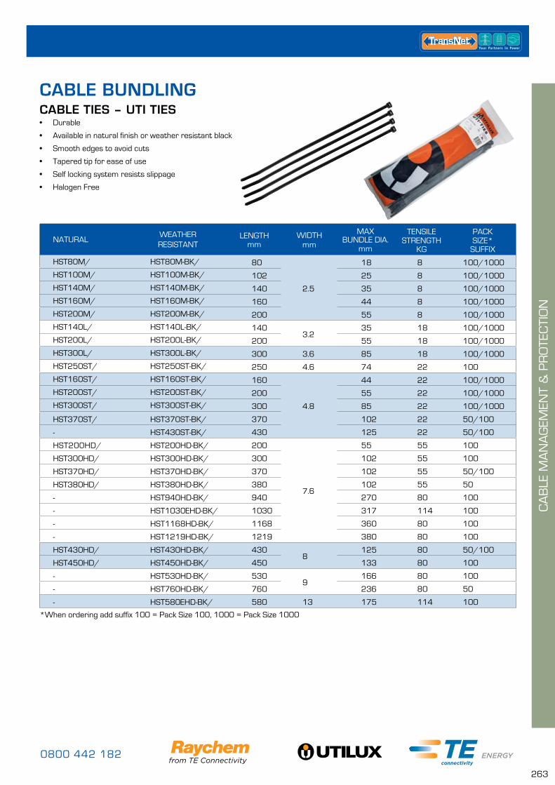
0800 442 182
263
CA
BLE
MA
NA
GEM
ENT
& P
RO
TEC
TIO
N
NATURALWEATHERRESISTANT
LENGTH mm
WIDTHmm
MAXBUNDLE DIA.
mm
TENSILE STRENGTH
KG
PACKSIZE*
SUFFIX
HST80M/ HST80M-BK/ 80
2.5
18 8 100/1000
HST100M/ HST100M-BK/ 102 25 8 100/1000
HST140M/ HST140M-BK/ 140 35 8 100/1000
HST160M/ HST160M-BK/ 160 44 8 100/1000
HST200M/ HST200M-BK/ 200 55 8 100/1000
HST140L/ HST140L-BK/ 1403.2
35 18 100/1000
HST200L/ HST200L-BK/ 200 55 18 100/1000
HST300L/ HST300L-BK/ 300 3.6 85 18 100/1000
HST250ST/ HST250ST-BK/ 250 4.6 74 22 100
HST160ST/ HST160ST-BK/ 160
4.8
44 22 100/1000
HST200ST/ HST200ST-BK/ 200 55 22 100/1000
HST300ST/ HST300ST-BK/ 300 85 22 100/1000
HST370ST/ HST370ST-BK/ 370 102 22 50/100
- HST430ST-BK/ 430 125 22 50/100
HST200HD/ HST200HD-BK/ 200
7.6
55 55 100
HST300HD/ HST300HD-BK/ 300 102 55 100
HST370HD/ HST370HD-BK/ 370 102 55 50/100
HST380HD/ HST380HD-BK/ 380 102 55 50
- HST940HD-BK/ 940 270 80 100
- HST1030EHD-BK/ 1030 317 114 100
- HST1168HD-BK/ 1168 360 80 100
- HST1219HD-BK/ 1219 380 80 100
HST430HD/ HST430HD-BK/ 4308
125 80 50/100
HST450HD/ HST450HD-BK/ 450 133 80 100
- HST530HD-BK/ 5309
166 80 100
- HST760HD-BK/ 760 236 80 50
- HST580EHD-BK/ 580 13 175 114 100
*When ordering add suffix 100 = Pack Size 100, 1000 = Pack Size 1000
CABLE TIES – UTI TIES• Durable
• Available in natural finish or weather resistant black
• Smooth edges to avoid cuts
• Tapered tip for ease of use
• Self locking system resists slippage
• Halogen Free
CABLE BUNDLING
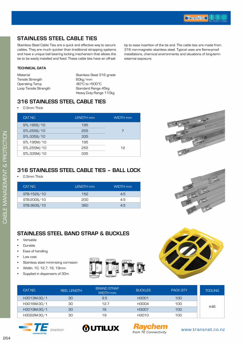
www.transnet.co.nz
264
CA
BLE
MA
NA
GEM
ENT
& P
RO
TEC
TIO
N
316 STAINLESS STEEL CABLE TIES• 0.3mm Thick
CAT NO. LENGTH mm WIDTH mm
STL-195S/10 195
7STL-255S/10 255
STL-335S/10 335
STL-195M/10 195
12STL-255M/10 255
STL-335M/10 335
316 STAINLESS STEEL CABLE TIES – BALL LOCK• 0.3mm Thick
CAT NO. LENGTH mm WIDTH mm
STB-152S/10 152 4.5
STB-200S/10 200 4.5
STB-360S/10 360 4.5
Stainless Steel Cable Ties are a quick and effective way to secure cables. They are much quicker than traditional strapping systems and have a unique ball bearing locking mechanism that allows the tie to be easily installed and fixed. These cable ties have an off-set
STAINLESS STEEL CABLE TIES
TECHNICAL DATA
Material Stainless Steel 316 gradeTensile Strength 60kg/mm²
Operating Temp -80°C to >500°CLoop Tensile Strength Standard Range 45kg Heavy Duty Range 110kg
CAT NO. REEL LENGTHBRAND STRAP
WIDTH mmBUCKLES PACK QTY TOOLING
H3013M-30/1 30 9.5 H3001 100
#46H3016M-30/1 30 12.7 H3004 100
H3019M-30/1 30 16 H3007 100
H3022M-30/1 30 19 H3010 100
• Versatile
• Durable
• Ease of handling
• Low cost
• Stainless steel minimising corrosion
• Width: 10, 12.7, 16, 19mm
• Supplied in dispensers of 30m
STAINLESS STEEL BAND STRAP & BUCKLES
tip to ease insertion of the tie end. The cable ties are made from 316 non-magnetic stainless steel. Typical uses are flame-proof installations, chemical environments and situations of long-term external exposure.
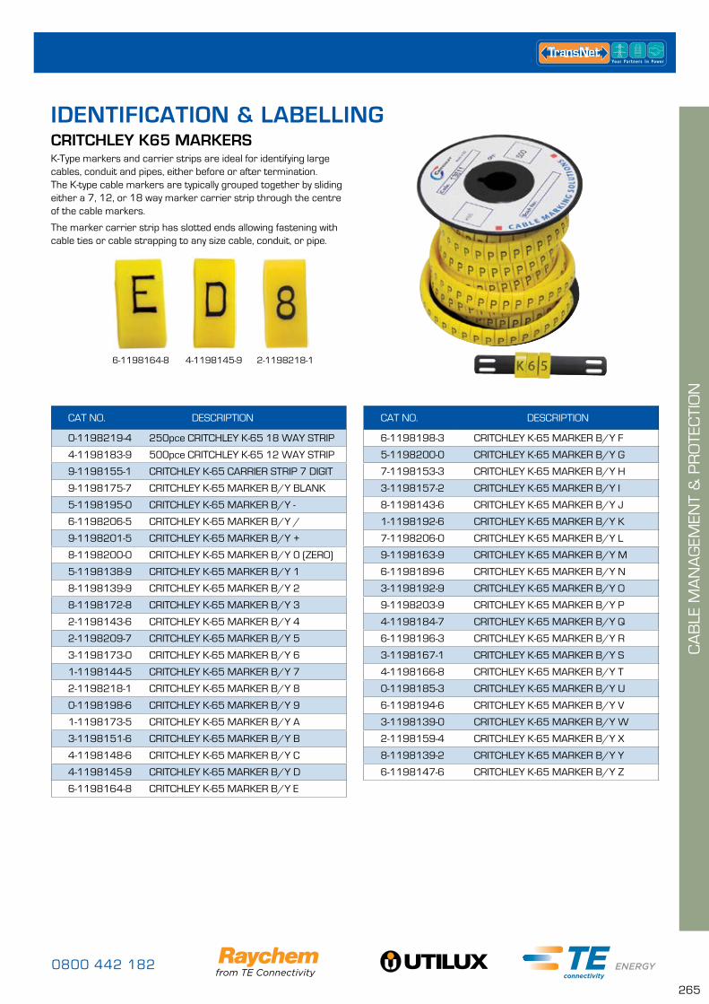
0800 442 182
265
CA
BLE
MA
NA
GEM
ENT
& P
RO
TEC
TIO
N
CAT NO. DESCRIPTION
0-1198219-4 250pce CRITCHLEY K-65 18 WAY STRIP
4-1198183-9 500pce CRITCHLEY K-65 12 WAY STRIP
9-1198155-1 CRITCHLEY K-65 CARRIER STRIP 7 DIGIT
9-1198175-7 CRITCHLEY K-65 MARKER B/Y BLANK
5-1198195-0 CRITCHLEY K-65 MARKER B/Y -
6-1198206-5 CRITCHLEY K-65 MARKER B/Y /
9-1198201-5 CRITCHLEY K-65 MARKER B/Y +
8-1198200-0 CRITCHLEY K-65 MARKER B/Y 0 (ZERO)
5-1198138-9 CRITCHLEY K-65 MARKER B/Y 1
8-1198139-9 CRITCHLEY K-65 MARKER B/Y 2
8-1198172-8 CRITCHLEY K-65 MARKER B/Y 3
2-1198143-6 CRITCHLEY K-65 MARKER B/Y 4
2-1198209-7 CRITCHLEY K-65 MARKER B/Y 5
3-1198173-0 CRITCHLEY K-65 MARKER B/Y 6
1-1198144-5 CRITCHLEY K-65 MARKER B/Y 7
2-1198218-1 CRITCHLEY K-65 MARKER B/Y 8
0-1198198-6 CRITCHLEY K-65 MARKER B/Y 9
1-1198173-5 CRITCHLEY K-65 MARKER B/Y A
3-1198151-6 CRITCHLEY K-65 MARKER B/Y B
4-1198148-6 CRITCHLEY K-65 MARKER B/Y C
4-1198145-9 CRITCHLEY K-65 MARKER B/Y D
6-1198164-8 CRITCHLEY K-65 MARKER B/Y E
CRITCHLEY K65 MARKERSK-Type markers and carrier strips are ideal for identifying large cables, conduit and pipes, either before or after termination. The K-type cable markers are typically grouped together by sliding either a 7, 12, or 18 way marker carrier strip through the centre of the cable markers.
The marker carrier strip has slotted ends allowing fastening with cable ties or cable strapping to any size cable, conduit, or pipe.
CAT NO. DESCRIPTION
6-1198198-3 CRITCHLEY K-65 MARKER B/Y F
5-1198200-0 CRITCHLEY K-65 MARKER B/Y G
7-1198153-3 CRITCHLEY K-65 MARKER B/Y H
3-1198157-2 CRITCHLEY K-65 MARKER B/Y I
8-1198143-6 CRITCHLEY K-65 MARKER B/Y J
1-1198192-6 CRITCHLEY K-65 MARKER B/Y K
7-1198206-0 CRITCHLEY K-65 MARKER B/Y L
9-1198163-9 CRITCHLEY K-65 MARKER B/Y M
6-1198189-6 CRITCHLEY K-65 MARKER B/Y N
3-1198192-9 CRITCHLEY K-65 MARKER B/Y O
9-1198203-9 CRITCHLEY K-65 MARKER B/Y P
4-1198184-7 CRITCHLEY K-65 MARKER B/Y Q
6-1198196-3 CRITCHLEY K-65 MARKER B/Y R
3-1198167-1 CRITCHLEY K-65 MARKER B/Y S
4-1198166-8 CRITCHLEY K-65 MARKER B/Y T
0-1198185-3 CRITCHLEY K-65 MARKER B/Y U
6-1198194-6 CRITCHLEY K-65 MARKER B/Y V
3-1198139-0 CRITCHLEY K-65 MARKER B/Y W
2-1198159-4 CRITCHLEY K-65 MARKER B/Y X
8-1198139-2 CRITCHLEY K-65 MARKER B/Y Y
6-1198147-6 CRITCHLEY K-65 MARKER B/Y Z
6-1198164-8 4-1198145-9 2-1198218-1
IDENTIFICATION & LABELLING
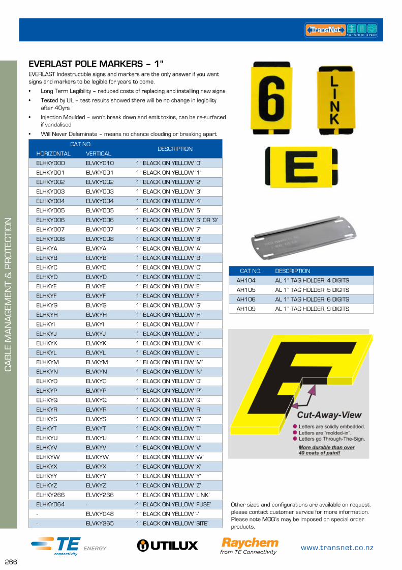
www.transnet.co.nz
266
CA
BLE
MA
NA
GEM
ENT
& P
RO
TEC
TIO
N
CAT NO.DESCRIPTION
HORIZONTAL VERTICAL
ELHKY000 ELVKY010 1” BLACK ON YELLOW ‘0’
ELHKY001 ELVKY001 1” BLACK ON YELLOW ‘1’
ELHKY002 ELVKY002 1” BLACK ON YELLOW ‘2’
ELHKY003 ELVKY003 1” BLACK ON YELLOW ‘3’
ELHKY004 ELVKY004 1” BLACK ON YELLOW ‘4’
ELHKY005 ELVKY005 1” BLACK ON YELLOW ‘5’
ELHKY006 ELVKY006 1” BLACK ON YELLOW ‘6’ OR ‘9’
ELHKY007 ELVKY007 1” BLACK ON YELLOW ‘7’
ELHKY008 ELVKY008 1” BLACK ON YELLOW ‘8’
ELHKYA ELVKYA 1” BLACK ON YELLOW ‘A’
ELHKYB ELVKYB 1” BLACK ON YELLOW ‘B’
ELHKYC ELVKYC 1” BLACK ON YELLOW ‘C’
ELHKYD ELVKYD 1” BLACK ON YELLOW ‘D’
ELHKYE ELVKYE 1” BLACK ON YELLOW ‘E’
ELHKYF ELVKYF 1” BLACK ON YELLOW ‘F’
ELHKYG ELVKYG 1” BLACK ON YELLOW ‘G’
ELHKYH ELVKYH 1” BLACK ON YELLOW ‘H’
ELHKYI ELVKYI 1” BLACK ON YELLOW ‘I’
ELHKYJ ELVKYJ 1” BLACK ON YELLOW ‘J’
ELHKYK ELVKYK 1” BLACK ON YELLOW ‘K’
ELHKYL ELVKYL 1” BLACK ON YELLOW ‘L’
ELHKYM ELVKYM 1” BLACK ON YELLOW ‘M’
ELHKYN ELVKYN 1” BLACK ON YELLOW ‘N’
ELHKYO ELVKYO 1” BLACK ON YELLOW ‘O’
ELHKYP ELVKYP 1” BLACK ON YELLOW ‘P’
ELHKYQ ELVKYQ 1” BLACK ON YELLOW ‘Q’
ELHKYR ELVKYR 1” BLACK ON YELLOW ‘R’
ELHKYS ELVKYS 1” BLACK ON YELLOW ‘S’
ELHKYT ELVKYT 1” BLACK ON YELLOW ‘T’
ELHKYU ELVKYU 1” BLACK ON YELLOW ‘U’
ELHKYV ELVKYV 1” BLACK ON YELLOW ‘V’
ELHKYW ELVKYW 1” BLACK ON YELLOW ‘W’
ELHKYX ELVKYX 1” BLACK ON YELLOW ‘X’
ELHKYY ELVKYY 1” BLACK ON YELLOW ‘Y’
ELHKYZ ELVKYZ 1” BLACK ON YELLOW ‘Z’
ELHKY266 ELVKY266 1” BLACK ON YELLOW ‘LINK’
ELHKY064 - 1” BLACK ON YELLOW ‘FUSE’
- ELVKY048 1” BLACK ON YELLOW ‘-’
- ELVKY265 1” BLACK ON YELLOW ‘SITE’
EVERLAST POLE MARKERS – 1"EVERLAST Indestructible signs and markers are the only answer if you want signs and markers to be legible for years to come.
• Long Term Legibility – reduced costs of replacing and installing new signs
• Tested by UL – test results showed there will be no change in legibility after 40yrs
• Injection Moulded – won’t break down and emit toxins, can be re-surfaced if vandalised
• Will Never Delaminate – means no chance clouding or breaking apart
Other sizes and configurations are available on request, please contact customer service for more information. Please note MOQ’s may be imposed on special order products.
CAT NO. DESCRIPTION
AH104 AL 1” TAG HOLDER, 4 DIGITS
AH105 AL 1” TAG HOLDER, 5 DIGITS
AH106 AL 1” TAG HOLDER, 6 DIGITS
AH109 AL 1” TAG HOLDER, 9 DIGITS
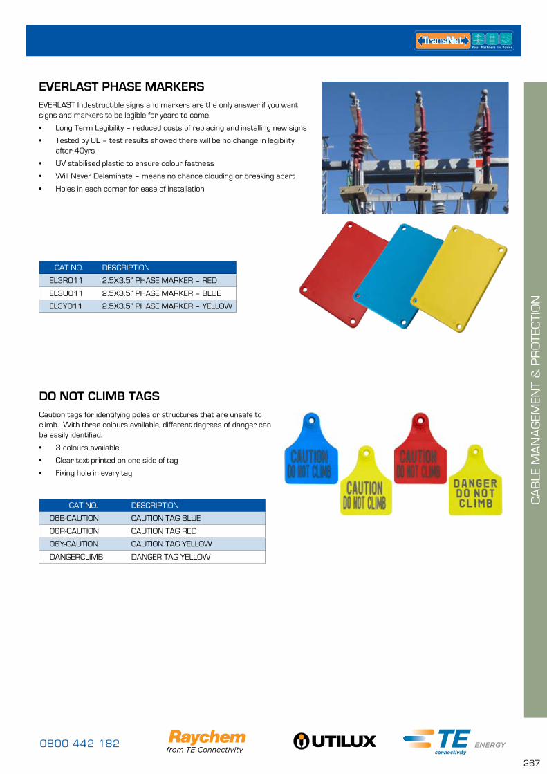
0800 442 182
267
CA
BLE
MA
NA
GEM
ENT
& P
RO
TEC
TIO
N
CAT NO. DESCRIPTION
EL3R011 2.5X3.5” PHASE MARKER – RED
EL3U011 2.5X3.5” PHASE MARKER – BLUE
EL3Y011 2.5X3.5” PHASE MARKER – YELLOW
EVERLAST PHASE MARKERSEVERLAST Indestructible signs and markers are the only answer if you want signs and markers to be legible for years to come.
• Long Term Legibility – reduced costs of replacing and installing new signs
• Tested by UL – test results showed there will be no change in legibility after 40yrs
• UV stabilised plastic to ensure colour fastness
• Will Never Delaminate – means no chance clouding or breaking apart
• Holes in each corner for ease of installation
CAT NO. DESCRIPTION
06B-CAUTION CAUTION TAG BLUE
06R-CAUTION CAUTION TAG RED
06Y-CAUTION CAUTION TAG YELLOW
DANGERCLIMB DANGER TAG YELLOW
DO NOT CLIMB TAGSCaution tags for identifying poles or structures that are unsafe to climb. With three colours available, different degrees of danger can be easily identified.
• 3 colours available
• Clear text printed on one side of tag
• Fixing hole in every tag
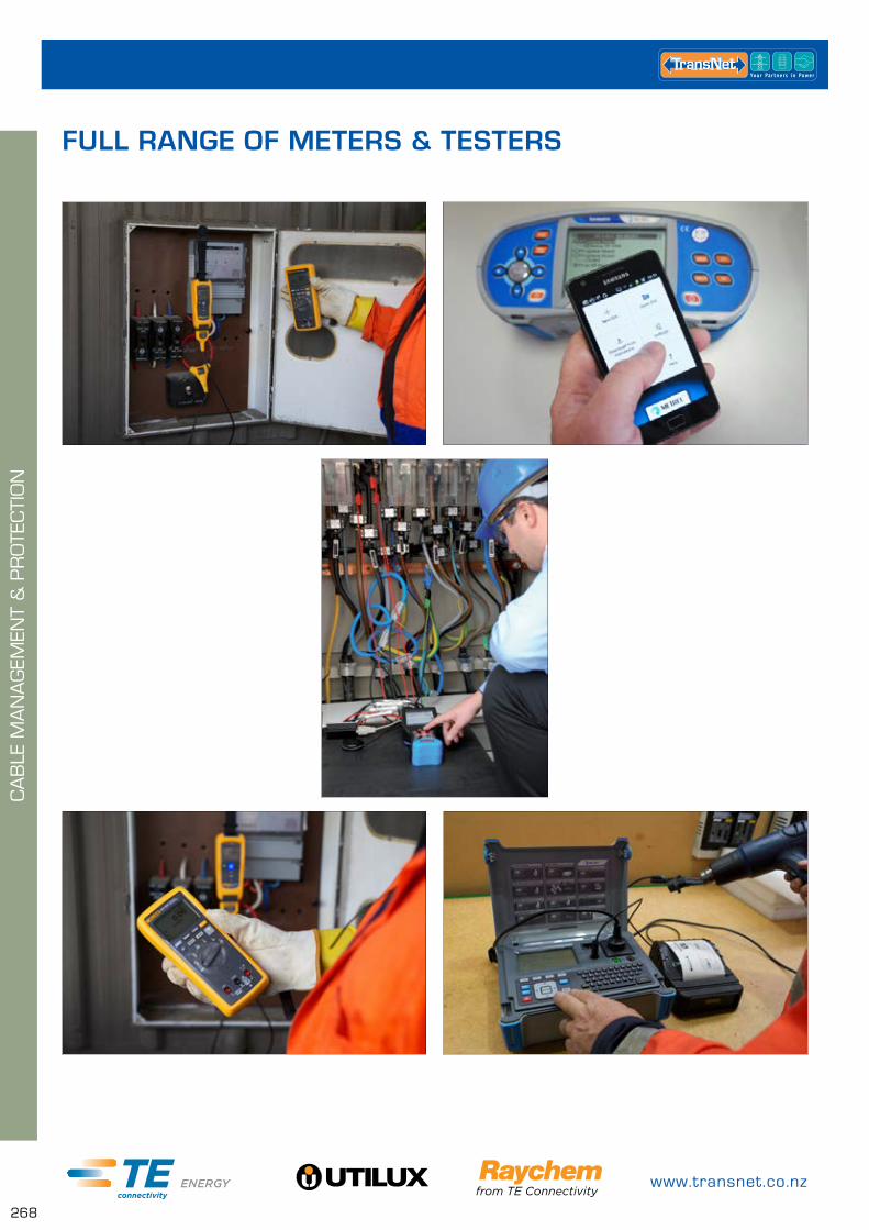
www.transnet.co.nz
268
CA
BLE
MA
NA
GEM
ENT
& P
RO
TEC
TIO
N
FULL RANGE OF METERS & TESTERS
0800 442 182
269
TES
T &
MEA
SU
REM
ENT
CLAMP METERS PAGE
FLUKE-381 270
FLUKE-376 270
MD9270 271
MARCM67 271
MD9240 271
MARCM58 272
MULTIMETERS PAGE
M249A 272
FLUKE-289 273
MD9040 273
CONTACT VOLTAGE DETECTORS PAGE
225HVD 274
NON CONTACT VOLTAGE DETECTORS PAGE
TNLVD-17 274
TNLVD-15 274
TN275NZHP 275
TN275NZHP-HANDLE 275
TIC-300PRO 275
CONTINUITY TESTERS PAGE
METRAVOLT12D+L 276
FLUKE-T130 276
FLUKE-T150 276
M611E 277
EARTH TESTING PAGE
MI2126 277
MARTL78 278
IET15M 278
PORTABLE APPLIANCE TESTERS PAGE
MI3309 278
TRANSDELTA4 278
POWER QUALITY ANALYSERS PAGE
MI2x92 Series 279
HV INSULATION TESTERS PAGE
MI3201 279
MI3200 280
MICROOHM TESTERS PAGE
MI3252 280
MI3250 280
MI3242 280
PHASE TESTERS PAGE
MARPSI4000 281
TN895PR 281
TN855 281
CABLE LOCATORS PAGE
CSCOPE 282
TOMKAT2 282
TEST & MEASUREMENT

www.transnet.co.nz
270
TES
T &
MEA
SU
REM
ENT
CLAMP METERS
CAT NO. DESCRIPTION
FLUKE-376 FLUKE TRMS AC/DC CLAMP C/W IFLEX
MEASUREMENT FUNCTIONS
• 1000A AC/DC current via Jaw
• 2500A AC current Via iFlex™
• True-RMS AC/DC Voltage
• Resistance
• Frequency
• Continuity
• MIN/MAX, average and inrush recording
FLUKE-376The new iFlex™ series from Fluke offers the ability to measure large and often difficult to access conductors up to 2500A. The flexible current probe provides improved access to cables in tight and cramped spaces.
CAT NO. DESCRIPTION
FLUKE-381 FLUKE DETACHABLE TRMS AC/DC CLAMP C
MEASUREMENT FUNCTIONS
• Wireless technology allows the display to be carried up to 30 ft. away from the point of measurement for added flexibility without interference with measurement accuracy
• The removable magnetic display can be conveniently mounted where it is easily seen
• iFlex flexible current probe expands the measurement range to 2500A AC
• CAT IV 600V, CATIII 1000V
• Integrated low pass filter and state of the art signal processing allows for use in noisy electrical environments while providing stable readings
• Proprietary inrush measurement technology to filter out noise and capture motor starting current exactly as the circuit protection sees it
• Ergonomic design fits in your hand and can be used while wearing protective equipment
FLUKE-381• Radio transmitter automatically sets the correct
measurement range so you do not need to change the switch positions while taking a measurement
The new Fluke 381 does everything you would expect from a clamp meter, and then lets you remove the display for even more flexibility. Now one technician can do jobs that used to require two people. Clamp the Fluke 381 around a conductor, remove the display and walk across the room to operate controls or remove protective equipment, all while watching real-time readings.
The new iFlex flexible current probe (included) expands the measurement range to 2500A AC while providing increased display flexibility, ability to measure awkward sized conductors and improved wire access.

0800 442 182
271
TES
T &
MEA
SU
REM
ENT
MARCM67 EARTH LEAKAGE CLAMP METERKEY FEATURES
• Measure earth leakage 0 – 300mA
• Identifies the cause of RCDs tripping
• Display hold feature
• Low pass filter eliminates false readings
CAT NO. DESCRIPTION
MARCM67 MARTINDALE EARTH LEAKAGE CLAMP METER
CAT NO. DESCRIPTION
MD9270 TRMS LEAKAGE CLAMP METER WITH POWER FUNCTIONS, CAT III/600V
KEY FEATURES
• TRMS: accurate measurements on sinusoidal and non-sinusoidal signals.• Jaw size: 31 mm shielded Jaw allows the clamp meter to be used in the noisiest environments.• AC current readings with accuracy of 0.8 % & base resolution of 0.01mA and voltage with 0.5%
accuracy & base resolution of 0.1V.• Various power parameters – active/reactive/apparent power/THD/PF/phase displacement.• Intelligent loss analysis, complex algorithms detect loss & allow possible reasons for current loss.• Measures current or voltage harmonic components & a percentage value up to 49th of a harmonic.• Dual display for readings with Total Harmonic Distortion (THD) or Power Factor (PF).• Peak value: the peak value of the waveform or crest factor can be displayed.• MAX/MIN/HOLD mode: displays maximum, minimum or average measured value.
MD9270 TRMS LEAKAGE CLAMP METER
MEASURING FUNCTIONS
• TRMS AC voltage and current measurement.
• Frequency measurement.
• Power parameters measurement.
CAT NO. DESCRIPTION
MD9240 POWER SYSTEM MAINTENANCE INDUSTRIAL CLAMP METER
KEY FEATURES
• High current: measures up to 1000A AC
• Autocheck function: automatic detection of AC voltage, DC voltage or AC current
• Power measures various power parameters (active, reactive, apparent power, THD, PF)
• Temperature: measures temperature in Celsius up to 300°C and 572°F
• PC Link: test results can be downloaded to the computer via the optional PC software
MD9240 TRMS POWER CLAMP METER
MEASURING FUNCTIONS
• TRMS AC/DC voltage measurement
• TRMS AC current measurement
• Frequency measurement
• Resistance measurement
• Continuity test
• Temperature measurement
• Power parameters measurement
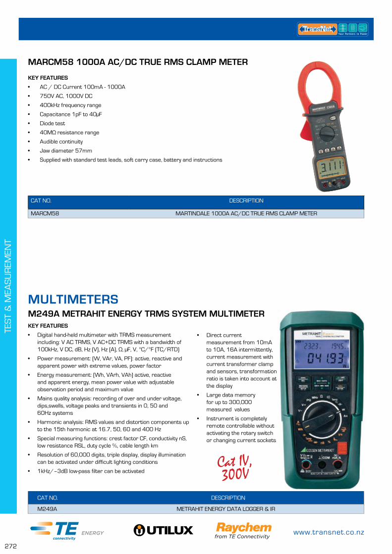
www.transnet.co.nz
272
TES
T &
MEA
SU
REM
ENT
MULTIMETERS
KEY FEATURES
• Digital hand-held multimeter with TRMS measurement including: V AC TRMS, V AC+DC TRMS with a bandwidth of 100kHz, V DC, dB, Hz (V), Hz (A), Ω, μF, V, °C/°F (TC/RTD)
• Power measurement: (W, VAr, VA, PF): active, reactive and apparent power with extreme values, power factor
• Energy measurement: (Wh, VArh, VAh) active, reactive and apparent energy, mean power value with adjustable observation period and maximum value
• Mains quality analysis: recording of over and under voltage, dips,swells, voltage peaks and transients in 0, 50 and 60Hz systems
• Harmonic analysis: RMS values and distortion components up to the 15th harmonic at 16.7, 50, 60 and 400 Hz
• Special measuring functions: crest factor CF, conductivity nS, low resistance RSL, duty cycle %, cable length km
• Resolution of 60,000 digits, triple display, display illumination can be activated under difficult lighting conditions
• 1kHz/–3dB low-pass filter can be activated
M249A METRAHIT ENERGY TRMS SYSTEM MULTIMETER
• Direct current measurement from 10mA to 10A, 16A intermittently, current measurement with current transformer clamp and sensors, transformation ratio is taken into account at the display
• Large data memory for up to 300,000 measured values
• Instrument is completely remote controllable without activating the rotary switch or changing current sockets
CAT NO. DESCRIPTION
M249A METRAHIT ENERGY DATA LOGGER & IR
Cat IV, 300V
MARCM58 1000A AC/DC TRUE RMS CLAMP METER
KEY FEATURES
• AC / DC Current 100mA - 1000A
• 750V AC, 1000V DC
• 400kHz frequency range
• Capacitance 1pF to 40µF
• Diode test
• 40MΩ resistance range
• Audible continuity
• Jaw diameter 57mm
• Supplied with standard test leads, soft carry case, battery and instructions
CAT NO. DESCRIPTION
MARCM58 MARTINDALE 1000A AC/DC TRUE RMS CLAMP METER

0800 442 182
273
TES
T &
MEA
SU
REM
ENT
Cat IV, 1000V
CAT NO. DESCRIPTION
MD9040 INDUSTRIAL HIGH LEVEL FAULT FINDING MULTIMETER, CAT IV, 1000V, AC/DC
MD9040 TRMS INDUSTRIAL DIGITAL MULTIMETER
MEASURING FUNCTIONS
• TRMS AC/DC current measurement
• Capacitance/Resistance /Diode test
• Mains supply frequency measurement
• Frequency of digital signals
• Continuity test (acoustic signalling)
KEY FEATURES
• Lead alert: identifies incorrect lead connection
• Auto-ranging: user can switch between auto and manual
• MAX/MIN/AVG: recording of max/min/avg values
• Data Hold feature freezes the display for later view
• PC Link: download test results via the optional PC software
• Frequency measurement: up to 1MHz
• Safety: CAT IV, 1000V overvoltage protection
FLUKE-289 DIGITAL MULTIMETER
KEY FEATURES
• Logging function with trend capture
• Multiple readings provide more information at a glance
• PC Interface
• Co-pass filter for motor drives
• True-RMS measurement
• Internal memory (up to 180h)
• IP54
• CATIV/600V
CAT NO. DESCRIPTION
FLUKE-289 ADVANCE DIAGNOSTIC AND LOGGING MULTIMETER, CATIV/600V
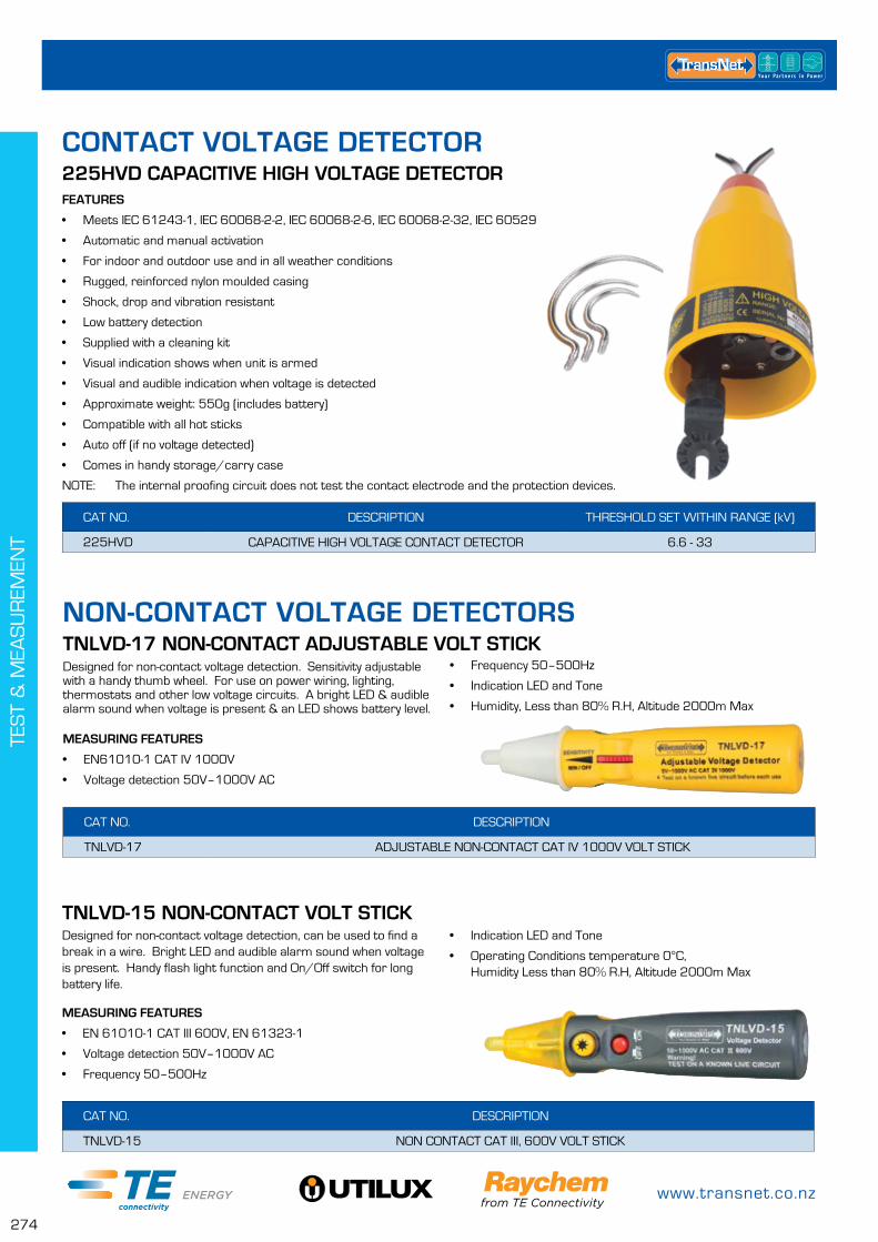
www.transnet.co.nz
274
TES
T &
MEA
SU
REM
ENT
NON-CONTACT VOLTAGE DETECTORS
CONTACT VOLTAGE DETECTOR
TNLVD-17 NON-CONTACT ADJUSTABLE VOLT STICKDesigned for non-contact voltage detection. Sensitivity adjustable with a handy thumb wheel. For use on power wiring, lighting, thermostats and other low voltage circuits. A bright LED & audible alarm sound when voltage is present & an LED shows battery level.
MEASURING FEATURES
• EN61010-1 CAT IV 1000V
• Voltage detection 50V–1000V AC
CAT NO. DESCRIPTION
TNLVD-17 ADJUSTABLE NON-CONTACT CAT IV 1000V VOLT STICK
• Frequency 50–500Hz
• Indication LED and Tone
• Humidity, Less than 80% R.H, Altitude 2000m Max
TNLVD-15 NON-CONTACT VOLT STICKDesigned for non-contact voltage detection, can be used to find a break in a wire. Bright LED and audible alarm sound when voltage is present. Handy flash light function and On/Off switch for long battery life.
MEASURING FEATURES
• EN 61010-1 CAT III 600V, EN 61323-1
• Voltage detection 50V–1000V AC
• Frequency 50–500Hz
CAT NO. DESCRIPTION
TNLVD-15 NON CONTACT CAT III, 600V VOLT STICK
• Indication LED and Tone
• Operating Conditions temperature 0°C, Humidity Less than 80% R.H, Altitude 2000m Max
225HVD CAPACITIVE HIGH VOLTAGE DETECTORFEATURES
• Meets IEC 61243-1, IEC 60068-2-2, IEC 60068-2-6, IEC 60068-2-32, IEC 60529
• Automatic and manual activation
• For indoor and outdoor use and in all weather conditions
• Rugged, reinforced nylon moulded casing
• Shock, drop and vibration resistant
• Low battery detection
• Supplied with a cleaning kit
• Visual indication shows when unit is armed
• Visual and audible indication when voltage is detected
• Approximate weight: 550g (includes battery)
• Compatible with all hot sticks
• Auto off (if no voltage detected)
• Comes in handy storage/carry case
NOTE: The internal proofing circuit does not test the contact electrode and the protection devices.
CAT NO. DESCRIPTION THRESHOLD SET WITHIN RANGE (kV)
225HVD CAPACITIVE HIGH VOLTAGE CONTACT DETECTOR 6.6 - 33
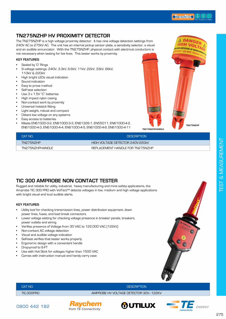
0800 442 182
275
TES
T &
MEA
SU
REM
ENT
TN275NZHP HV PROXIMITY DETECTORThe TN275NZHP is a high voltage proximity detector. It has nine voltage detection settings from 240V AC to 275kV AC. The unit has an internal pickup sensor plate, a sensitivity selector, a visual and an audible annunciator. With the TN275NZHP, physical contact with electrical conductors is not necessary when testing for live lines. This tester works by proximity.
KEY FEATURES
• Sealed by ‘O’ Rings• 9 voltage settings: 240V, 3.3kV, 6.6kV, 11kV, 22kV, 33kV, 66kV,
110kV & 220kV• High bright LEDs visual indication• Sound indication• Easy to prove method• Self test selection• Use 3 x 1.5V “C” batteries• High impact nylon casing• Non-contact work by proximity• Universal hotstick fitting• Light weight, robust and compact• Detect low voltage on any systems• Easy access to batteries• Meets EN61000-3-2, EN61000-3-3, EN61326-1, EN55011, EN61000-4-2,
EN61000-4-3, EN61000-4-4, EN61000-4-5, EN61000-4-6, EN61000-4-11
CAT NO. DESCRIPTION
TN275NZHP HIGH VOLTAGE DETECTOR 240V-220kV
TN275NZHPHANDLE REPLACEMENT HANDLE FOR TN275NZHP
TN275NZHPHANDLE
TN275NZHP
TIC 300 AMPROBE NON CONTACT TESTERRugged and reliable for utility, industrial, heavy manufacturing and mine safety applications, the Amprobe TIC 300 PRO with VolTect™ detects voltages in low, medium and high voltage applications with bright visual and loud audible alerts.
KEY FEATURES
• Utility tool for checking transmission lines, power distribution equipment, down power lines, fuses, and load break connectors
• Lower voltage setting for checking voltage presence in breaker panels, breakers, power outlets and wiring
• Verifies presence of Voltage from 30 VAC to 122,000 VAC (122kV)• Non-contact AC voltage detection• Visual and audible voltage indication• Self-test verifies that tester works properly• Ergonomic design with a convenient handle • Drop-proof to 6-FT• Use with Hot Stick for voltages higher than 1500 VAC• Comes with instruction manual and handy carry case
CAT NO. DESCRIPTION
TIC-300PRO AMPROBE HV VOLTAGE DETECTOR 30V–122KV

www.transnet.co.nz
276
TES
T &
MEA
SU
REM
ENT
CAT NO. DESCRIPTION
FLUKE-T130 VOLTAGE/CONTINUITY TESTER
FLUKE-T150 VOLTAGE/CONTINUITY TESTER WITH RESISTANCE MEASUREMENT
KEY FEATURES
• Large LCD Display• Backlight (T150 only)• Polarity indication• Visual and audible continuity test• Probe protection• Rugged IP65 casing• CAT IV, 600V
FLUKE-T130 & T150 VOLTAGE & CONTINUITY TESTER
MEASUREMENT FUNCTIONS
• Phase rotation • Resistance (T150 only)• Voltage AC/DC• Continuity frequency
CONTINUITY TESTERS
CAT NO. DESCRIPTION
METRAVOLT12D+L VOLTAGE & CONTINUITY TESTER WITH PHASE, POLARITY & PHASE SEQUENCING, 1M LEAD
KEY FEATURES
• 1m lead between test probes• Voltage & Continuity tester with Phase,
Polarity & Phase Sequence Testing• Fully automated measuring sequence – auto on when
voltage detected, auto off after 30sec of inactivity• Measured value storage – displayed value can
be locked on screen• Self test and battery monitoring – checks all display
elements & signal is generated if battery needs to be replaced
• Rugged housing – impact resistant, dust proof, IP65• High safety levels – series resistors integrated
into both test probes• CAT IV/600V
METRAVOLT12D+L MULTIFUNCTION CONTINUITY TESTERMEASUREMENT FUNCTIONS
• Voltage 24-1000V AC/1500V DC
• Resistance & Continuity• Phase• Polarity• Phase Sequence

0800 442 182
277
TES
T &
MEA
SU
REM
ENT
CAT NO. DESCRIPTION
M611E DUSPOL®, 2 POLE VOLTAGE TESTER
M611E DUSPOL CONTINUITY TESTERKEY FEATURES
• Direct display without activating a pushbutton – high-resistance test• Load connection via pushbutton – low-resistance test• Continuity test via buzzer and LED and/or LCD• Vibration alert in tester handle• Illumination of measuring point• Rugged housing with rubberized grip• Impact resistant, dust-tight and splashing
water protected housing (IP 65)• Safety always and everywhere
MEASUREMENT FEATURES
• Single pole phase test• Continuity test• Voltage indicator• Polarity test
EARTH TESTING
CAT NO. DESCRIPTION
MI2126 EARTH 2/3 SINGLE FUNCTION STANDARD SET
The MI2126 Earth 2/3 is a high quality, professional grade test instrument for performing three-wire earth resistance measurements in accordance with European standard EN61557-5, on which the estimation of earthing quality is based.
KEY FEATURES
• Instrument performs standard 3 wire earth resistance tests with two earthing rods
• Easy to use: only 3 buttons control all the operations of the test instrument and instruction manual explains various earth resistance measuring methods
• Battery operated, can be easily placed with other test instruments for moving between tested items
• Reliable results even in the presence of stray currents• Outstanding repeatability of test results especially in the case
of high test probe resistance of various earthing structures (e.g. asphalt, sand, and stone)
MI2126 EARTH 2/3 SINGLE FUNCTION EARTH TESTER

www.transnet.co.nz
278
TES
T &
MEA
SU
REM
ENT
PORTABLE APPLIANCE TESTERS
CAT NO. DESCRIPTION
MI3309 HANDHELD APPLIANCE TESTER COMES WITH PC INTERFACE
TRANSDELTA4 DELTA GT COMPLETE WITH PRINTER, SCANNER, SOFTWARE & CABLES
MI3309 DELTA GTTHE FOLLOWING TESTS CAN BE PERFORMED
• Functional and visual inspection• Earth bond resistance• Insulation resistance of isolated accessible conductive parts• Substitute leakage current of isolated accessible conductive parts• Differential leakage current test• Touch leakage test• RCD test• Power test• IEC cord polarity test• TRMS voltage meter
CAT NO. DESCRIPTION
IET15M 15M LEAD, REEL & SPIKE FOR INDEPENDENT EARTH TESTING
IET15M INDEPENDENT EARTH TESTER REEL & SPIKEDesigned to attach to any voltage tester this reel and spike boasts 15m of lead and a sturdy spike to easily pierce even the hardest ground.
Simple to use, the Independent Earth Tester Reel and Spike has a connection point on the end of the lead to simply poke the tester probe into. The beauty of this set up is if your tester or lead fail you can easily replace them without having to replace the entire unit.
KEY FEATURES
• 15m lead• Sturdy spike• Connector on lead for voltage tester probe• Tester sold separately
MARTL78 50M GREEN R2 CONTINUITY WIRE
CAT NO. DESCRIPTION
MARTL78 50MTR GREEN R2 CONTINUITY WIRE ON A REEL
This handy carry case reel contains a high quality continuity cable for earth testing. The cable can be easily retracted by winding it up much like a hose reel.
KEY FEATURES
• 50m Green continuity cable• Handy Reel• Retractable tidy cable• Easy to use• Quick connectors

0800 442 182
279
TES
T &
MEA
SU
REM
ENT
POWER QUALITY ANALYSERS
CAT NO. DESCRIPTION
MI2892 3 PHASE POWER QUALITY METER WITH COLOUR LCD SCREEN & SD MEMORY SLOT UP TO 32GB
MI2792A POWER QUALITY WITH 4 INPUTS, GPS, TEMPERATURE/TRANSIENTS & REMOTE OPTION
MI2792 POWER QUALITY WITH 4 INPUTS, TEMPERATURE/TRANSIENTS & REMOTE (GPS OPTIONAL)
MI2592 POWER QUALITY WITH 4 INPUTS & FLICKER
MI2392 POWER QUALITY WITH 3 INPUTS INCLUDES SAGS, SWELLS & INTERRUPTIONS
MI2492 POWER QUALITY WITH 3 INPUTS – ENTRY LEVEL UNIT
The MI 2492 PowerQ is a lightweight, handheld, 3-phase analyser for quick power quality assessment in low and middle voltage systems. Download software included.
MEASURING FUNCTIONS:• TRMS voltage/current• Power (active, reactive, apparent)• Power factor, cos o• Energy (active, reactive, generated, consumed)• Harmonic analysis up to 50th harmonics, THD measurement• Phase diagram and unbalance• Oscilloscope mode
Units are listed below in order of functionality with the most functions at the top and the least at the bottom.
MI2x92 SERIES POWER QUALITY ANALYSERS
CAT NO. DESCRIPTION
MI3201 TERAOHM 5KV PLUS INSULATION TESTER
MI3201 TERAOHM 5KV PLUS
KEY FEATURES
• Measuring range up to 10TΩ
• DC test voltages: from 250V up to 5000V in steps of 25V
• Withstanding voltage: programmable ramp test voltage from 250V up to 5kV and programmable threshold current
• Step voltage: insulation resistance with five discrete proportionately set test voltages and programmable timer per step
• Automated testing: PI, DD, DAR calculations with automated resistance ranging. All data displayed during a single measurement
• Guard test terminal eliminations potential surface leakage currents
• Fault finding: fully programmable step & withstand voltage test functions assist in diagnosing faults in insulation
• Graph R(t): real time resistance against time graph plotting facility graphically illustrates the response of a material to a test voltage
• Programmable timer from 1s up to 30min
• Automatic discharge of tested object after test
• Fast testing: 5mA current source charges of capacitive load fast.
• Accurate selectable noise rejection filters and shielded test leads included in a standard set ensure accurate measurement
• Safe: high CAT IV/600V voltage protection
• Built-in charger & rechargeable NiMH batteries
• Portable lightweight 3kg design with carry handle and shoulder strap
HV INSULATION TESTERS

www.transnet.co.nz
280
TES
T &
MEA
SU
REM
ENT
CAT NO. DESCRIPTION
MI3252 MICRO OHM 100A TESTER
MI3250 MICRO OHM 10A TESTER
MI3242 MICRO OHM 2A TESTER
MI3252 MICROOHM 100AMI 3252 MicroOhm 100A is a portable low resistance ohmmeter used to measure low contact resistances of breakers and switches, busbars using test current from 100 mA to 100 A.
MICROOHM TESTERS
FEATURES
• Safe: sustain external voltages in case of wrong connection, protection level (CAT IV, 50 V); automatically detects continuity in current circuit.
• Single and continuous measuring mode.
• Portable: rugged carrying case with a handle and lightweight design
• High protection degree: IP 64.
• Accurate: 1 nΩ best resolution with 0.25% accuracy.
• Custom limits: the limits can be set for PASS or FAIL evaluation of test result.
• Measurements with 100 A for up to 10 mins on internal battery only.
• Memory: built-in memory enables storage of up to 1000 test results.
• Downloadable: downloads test results via RS232 or USB cable directly with software.
MEASURING FUNCTIONS
• Resistance measurement: wide measuring range (1 nΩ ... 20 Ω) adjustable test current (100 mA ... 100 A)
• Voltage drop measurement
• Bar graph: on screen resistance bar graph
CAT NO. DESCRIPTION
MI3200 TERAOHM 10KV INSULATION TESTER STANDARD SET
MI3210X NEW TERAOHM 10KV INSULATION TESTER WITH BLUETOOTH CAPABILITY
KEY FEATURES
• Measuring range up to 10TΩ• DC test voltages: from 500V up to 10,000V in steps of 25V• Testing of insulation with programmable ramp test voltage from 500V up to
10kV and programmable threshold current• Step voltage: insulation resistance with five discrete proportionately set test
voltages & programmable timer per step• Automated testing: PI, DD, DAR calculations with automated
resistance ranging. All data displayed during one measurement• Guard test terminal: for elimination of potential surface leakage currents• Fully programmable step & withstand voltage test functions assist in
diagnosing faults in insulation• Graph R(t): real time resistance against time graph plotting facility to
illustrate the response of a material to a test voltage• Built-in timer: programmable timer from 1s up to 30min• Automatic discharge of tested object after test• Fast testing: 5mA current source for quick capacitive load charging• Accurate: selectable noise rejection filters and shielded test leads included in
a standard set ensure accurate measurement• Safe: high CAT IV/600V voltage protection• Built-in charger & rechargeable NiMH batteries• Portable: lightweight 5.5kg design with carry handle
MI3200 & MI3210X TERAOHM 10KV – INSULATION TESTER
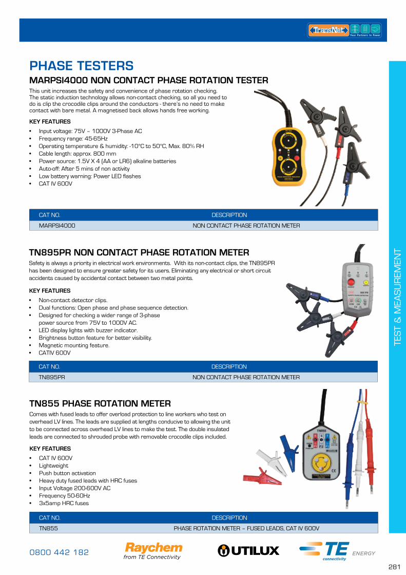
0800 442 182
281
TES
T &
MEA
SU
REM
ENT
CAT NO. DESCRIPTION
TN855 PHASE ROTATION METER – FUSED LEADS, CAT IV 600V
KEY FEATURES
• CAT IV 600V• Lightweight• Push button activation• Heavy duty fused leads with HRC fuses• Input Voltage 200-600V AC• Frequency 50-60Hz• 3x5amp HRC fuses
TN855 PHASE ROTATION METERComes with fused leads to offer overload protection to line workers who test on overhead LV lines. The leads are supplied at lengths conducive to allowing the unit to be connected across overhead LV lines to make the test. The double insulated leads are connected to shrouded probe with removable crocodile clips included.
CAT NO. DESCRIPTION
MARPSI4000 NON CONTACT PHASE ROTATION METER
KEY FEATURES
• Input voltage: 75V – 1000V 3-Phase AC• Frequency range: 45-65Hz• Operating temperature & humidity: -10°C to 50°C, Max. 80% RH• Cable length: approx. 800 mm • Power source: 1.5V X 4 (AA or LR6) alkaline batteries• Auto-off: After 5 mins of non activity• Low battery warning: Power LED flashes • CAT IV 600V
MARPSI4000 NON CONTACT PHASE ROTATION TESTERThis unit increases the safety and convenience of phase rotation checking. The static induction technology allows non-contact checking, so all you need to do is clip the crocodile clips around the conductors - there’s no need to make contact with bare metal. A magnetised back allows hands free working.
CAT NO. DESCRIPTION
TN895PR NON CONTACT PHASE ROTATION METER
KEY FEATURES
• Non-contact detector clips.• Dual functions: Open phase and phase sequence detection.• Designed for checking a wider range of 3-phase
power source from 75V to 1000V AC.• LED display lights with buzzer indicator.• Brightness button feature for better visibility.• Magnetic mounting feature. • CATIV 600V
TN895PR NON CONTACT PHASE ROTATION METERSafety is always a priority in electrical work environments. With its non-contact clips, the TN895PR has been designed to ensure greater safety for its users. Eliminating any electrical or short circuit accidents caused by accidental contact between two metal points.
PHASE TESTERS
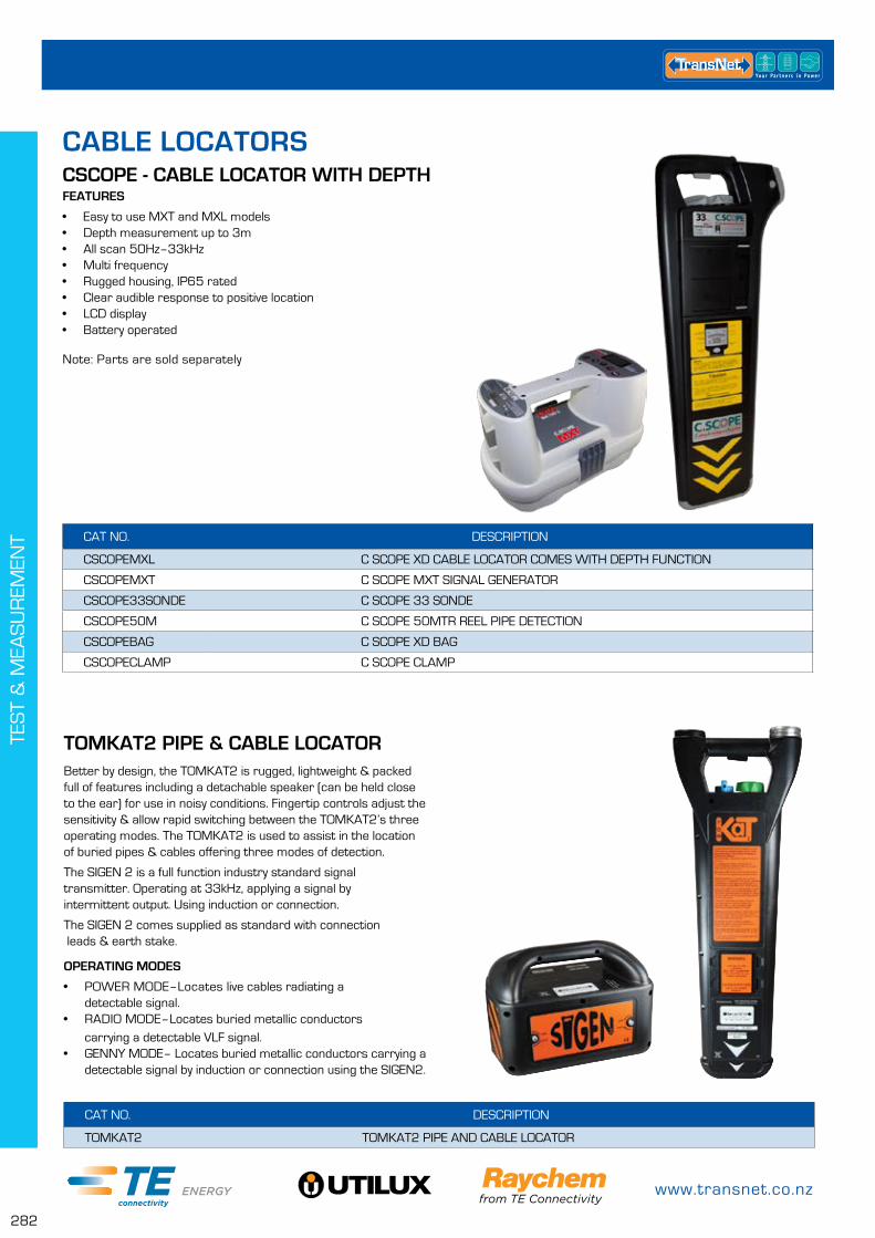
www.transnet.co.nz
282
TES
T &
MEA
SU
REM
ENT
CSCOPE - CABLE LOCATOR WITH DEPTH
CAT NO. DESCRIPTION
CSCOPEMXL C SCOPE XD CABLE LOCATOR COMES WITH DEPTH FUNCTION
CSCOPEMXT C SCOPE MXT SIGNAL GENERATOR
CSCOPE33SONDE C SCOPE 33 SONDE
CSCOPE50M C SCOPE 50MTR REEL PIPE DETECTION
CSCOPEBAG C SCOPE XD BAG
CSCOPECLAMP C SCOPE CLAMP
FEATURES
• Easy to use MXT and MXL models• Depth measurement up to 3m• All scan 50Hz–33kHz• Multi frequency• Rugged housing, IP65 rated• Clear audible response to positive location• LCD display• Battery operated
Note: Parts are sold separately
CAT NO. DESCRIPTION
TOMKAT2 TOMKAT2 PIPE AND CABLE LOCATOR
Better by design, the TOMKAT2 is rugged, lightweight & packed full of features including a detachable speaker (can be held close to the ear) for use in noisy conditions. Fingertip controls adjust the sensitivity & allow rapid switching between the TOMKAT2’s three operating modes. The TOMKAT2 is used to assist in the location of buried pipes & cables offering three modes of detection.
The SIGEN 2 is a full function industry standard signal transmitter. Operating at 33kHz, applying a signal by intermittent output. Using induction or connection.
The SIGEN 2 comes supplied as standard with connection leads & earth stake.
OPERATING MODES
• POWER MODE–Locates live cables radiating a detectable signal.
• RADIO MODE–Locates buried metallic conductors carrying a detectable VLF signal.
• GENNY MODE– Locates buried metallic conductors carrying a detectable signal by induction or connection using the SIGEN2.
TOMKAT2 PIPE & CABLE LOCATOR
CABLE LOCATORS
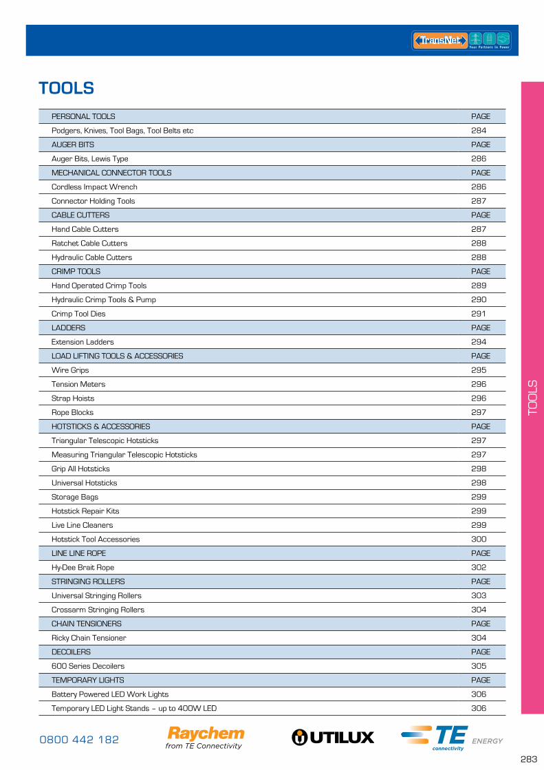
0800 442 182
283
TOO
LS
PERSONAL TOOLS PAGE
Podgers, Knives, Tool Bags, Tool Belts etc 284
AUGER BITS PAGE
Auger Bits, Lewis Type 286
MECHANICAL CONNECTOR TOOLS PAGE
Cordless Impact Wrench 286
Connector Holding Tools 287
CABLE CUTTERS PAGE
Hand Cable Cutters 287
Ratchet Cable Cutters 288
Hydraulic Cable Cutters 288
CRIMP TOOLS PAGE
Hand Operated Crimp Tools 289
Hydraulic Crimp Tools & Pump 290
Crimp Tool Dies 291
LADDERS PAGE
Extension Ladders 294
LOAD LIFTING TOOLS & ACCESSORIES PAGE
Wire Grips 295
Tension Meters 296
Strap Hoists 296
Rope Blocks 297
HOTSTICKS & ACCESSORIES PAGE
Triangular Telescopic Hotsticks 297
Measuring Triangular Telescopic Hotsticks 297
Grip All Hotsticks 298
Universal Hotsticks 298
Storage Bags 299
Hotstick Repair Kits 299
Live Line Cleaners 299
Hotstick Tool Accessories 300
LINE LINE ROPE PAGE
Hy-Dee Brait Rope 302
STRINGING ROLLERS PAGE
Universal Stringing Rollers 303
Crossarm Stringing Rollers 304
CHAIN TENSIONERS PAGE
Ricky Chain Tensioner 304
DECOILERS PAGE
600 Series Decoilers 305
TEMPORARY LIGHTS PAGE
Battery Powered LED Work Lights 306
Temporary LED Light Stands – up to 400W LED 306
TOOLS
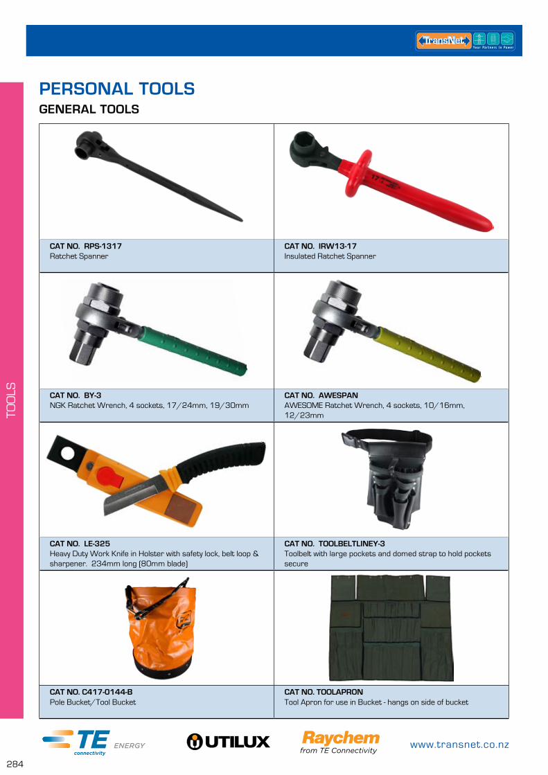
www.transnet.co.nz
284
TOO
LS
GENERAL TOOLS
PERSONAL TOOLS
CAT NO. RPS-1317 Ratchet Spanner
CAT NO. IRW13-17 Insulated Ratchet Spanner
CAT NO. BY-3 NGK Ratchet Wrench, 4 sockets, 17/24mm, 19/30mm
CAT NO. AWESPAN AWESOME Ratchet Wrench, 4 sockets, 10/16mm, 12/23mm
CAT NO. LE-325Heavy Duty Work Knife in Holster with safety lock, belt loop & sharpener. 234mm long (80mm blade)
CAT NO. TOOLBELTLINEY-3 Toolbelt with large pockets and domed strap to hold pockets secure
CAT NO. C417-0144-B Pole Bucket/Tool Bucket
CAT NO. TOOLAPRON Tool Apron for use in Bucket - hangs on side of bucket

0800 442 182
285
TOO
LS
CAT NO. 760-xxx1000V Adjustable Spanner, four sizes – 200mm, 250mm, 300mm & 380mm *xxx = size
CAT NO. 180323 16oz Claw Hammer, Fibreglass Handle, Rubber Grip
CAT NO. 123 1000V Rated Double Blade Cutter, For One Hand Use
CAT NO. 100K 1000V Rated, Heavy Duty Pliers with Extra Long Cutting Edges for Round Cables
CAT NO. 1019221000V Rated Flat Screwdriver 8mm x 175mm
CAT NO. 101916 1000V Rated Flat Screwdriver 4mm x 100mm
FOR OUR FULL RANGE OF TOOLS.....
For information on our complete range of tools and to discuss your requirements further please contact your local rep or our customer service team.
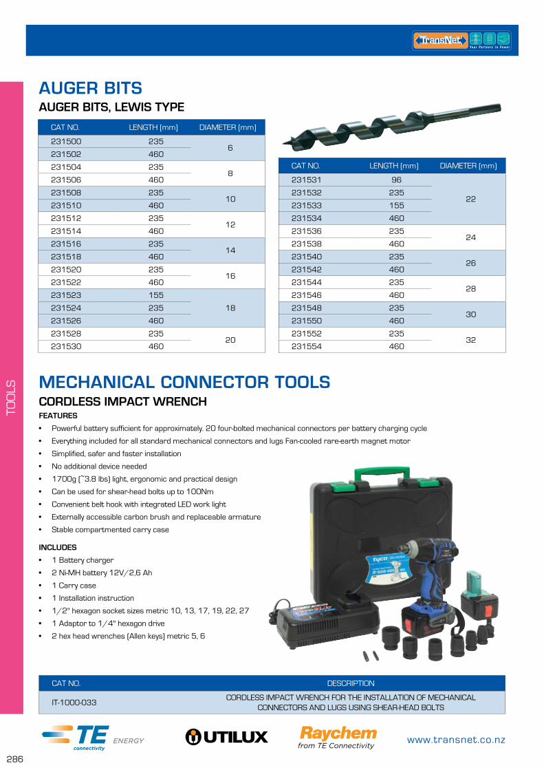
www.transnet.co.nz
286
TOO
LS
AUGER BITS, LEWIS TYPE
CAT NO. LENGTH (mm) DIAMETER (mm)
231500 2356
231502 460
231504 2358
231506 460
231508 23510
231510 460
231512 23512
231514 460
231516 23514
231518 460
231520 23516
231522 460
231523 155
18231524 235
231526 460
231528 23520
231530 460
CAT NO. LENGTH (mm) DIAMETER (mm)
231531 96
22231532 235
231533 155
231534 460
231536 23524
231538 460
231540 23526
231542 460
231544 23528
231546 460
231548 23530
231550 460
231552 23532
231554 460
MECHANICAL CONNECTOR TOOLS
CAT NO. DESCRIPTION
IT-1000-033CORDLESS IMPACT WRENCH FOR THE INSTALLATION OF MECHANICAL
CONNECTORS AND LUGS USING SHEAR-HEAD BOLTS
CORDLESS IMPACT WRENCHFEATURES
• Powerful battery sufficient for approximately. 20 four-bolted mechanical connectors per battery charging cycle
• Everything included for all standard mechanical connectors and lugs Fan-cooled rare-earth magnet motor
• Simplified, safer and faster installation
• No additional device needed
• 1700g (~3.8 lbs) light, ergonomic and practical design
• Can be used for shear-head bolts up to 100Nm
• Convenient belt hook with integrated LED work light
• Externally accessible carbon brush and replaceable armature
• Stable compartmented carry case
INCLUDES
• 1 Battery charger
• 2 Ni-MH battery 12V/2,6 Ah
• 1 Carry case
• 1 Installation instruction
• 1/2'' hexagon socket sizes metric 10, 13, 17, 19, 22, 27
• 1 Adaptor to 1/4" hexagon drive
• 2 hex head wrenches (Allen keys) metric 5, 6
AUGER BITS

0800 442 182
287
TOO
LS
TransNet offers both an insulated and un-insulated holding tool for Mechanical Connectors. Both can be used for most connector sizes.
• Large easy grip handle
• Recommended for use on most sizes of connector to eliminate possible core ‘cranking’
• IT-10000-019 has a large jaw opening to accommodate a wide range of mechanical connectors
• 233 is insulated to 1000V
MECHANICAL CONNECTOR HOLDING TOOLS
CAT NO. DESCRIPTION
IT-1000-019 UNIVERSAL HOLDING TOOL FOR MECHANICAL CONNECTORS
223 1000V INSULATED MECHANICAL CONNECTOR HOLDER
HAND CABLE CUTTERS
CAT NO. DESCRIPTION
#110/1Small single hand operated parrot beak style cutter, ideal for general applications. Precision blades make this tool ideal for cutting flexible Copper cables.
RANGE: 6 – 70mm² LENGTH: 240mm WEIGHT: 460g
CAT NO. DESCRIPTION
#144/1Parrot beak style cable cutter for Copper and Aluminium conductors.
RANGE: Up – 125mm² LENGTH: 300mm WEIGHT: 700g
CAT NO. DESCRIPTION
#140/1Parrot beak style cable cutter for Copper and Aluminium conductors. Replacement blades available. Not for use with steel core conductors.
RANGE: Up – 240mm² LENGTH: 610mm WEIGHT: 1.8kg
CAT NO. DESCRIPTION
#141/1
Parrot beak style cable cutter for Copper and Aluminium conductors. Replacement blades available. Not for use with Steel core conductors.
RANGE: Up – 500mm² LENGTH: 805mm WEIGHT: 2.8kg
CABLE CUTTERS
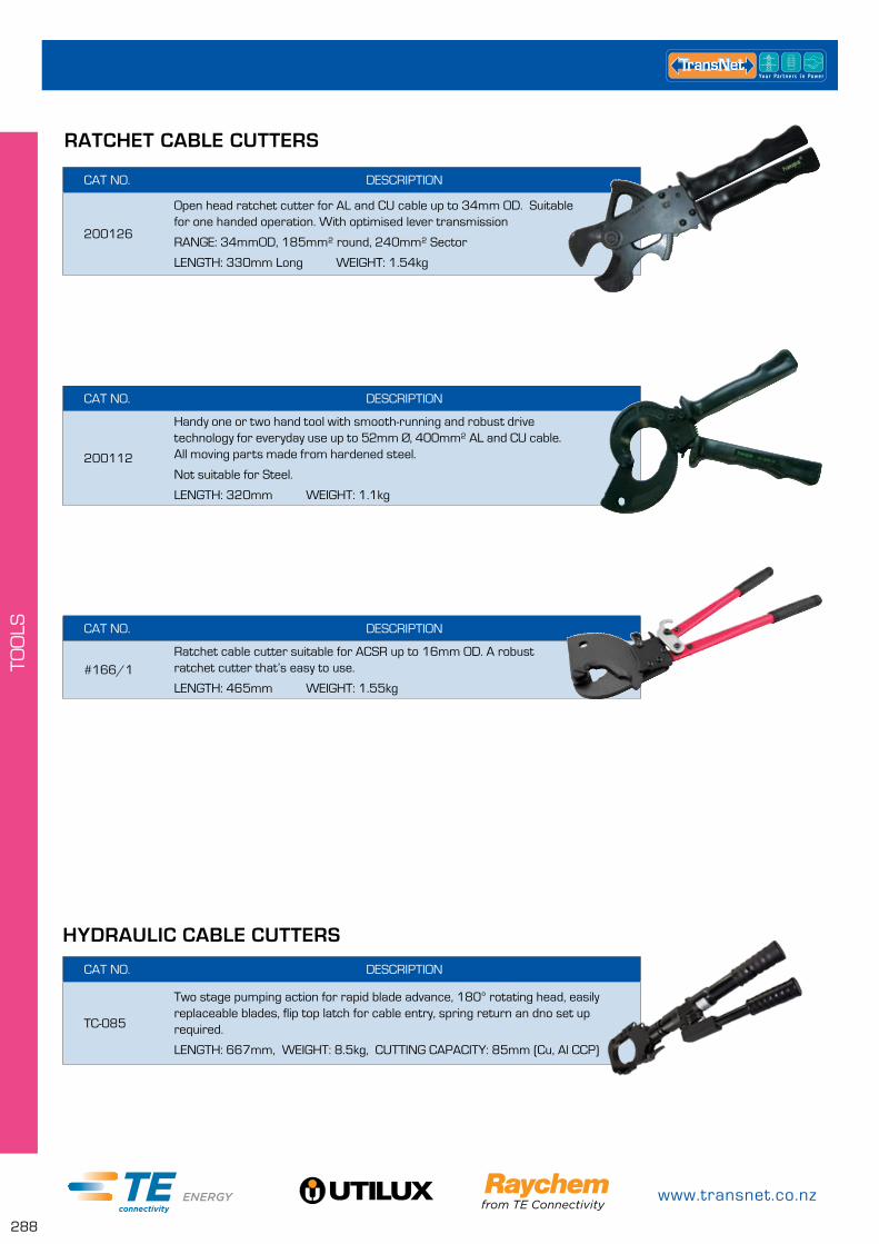
www.transnet.co.nz
288
TOO
LS
CAT NO. DESCRIPTION
200126
Open head ratchet cutter for AL and CU cable up to 34mm OD. Suitable for one handed operation. With optimised lever transmission
RANGE: 34mmOD, 185mm² round, 240mm² Sector
LENGTH: 330mm Long WEIGHT: 1.54kg
CAT NO. DESCRIPTION
200112
Handy one or two hand tool with smooth-running and robust drive technology for everyday use up to 52mm Ø, 400mm² AL and CU cable. All moving parts made from hardened steel.
Not suitable for Steel.
LENGTH: 320mm WEIGHT: 1.1kg
RATCHET CABLE CUTTERS
CAT NO. DESCRIPTION
#166/1Ratchet cable cutter suitable for ACSR up to 16mm OD. A robust ratchet cutter that’s easy to use.
LENGTH: 465mm WEIGHT: 1.55kg
HYDRAULIC CABLE CUTTERS
CAT NO. DESCRIPTION
TC-085
Two stage pumping action for rapid blade advance, 180° rotating head, easily replaceable blades, flip top latch for cable entry, spring return an dno set up required.
LENGTH: 667mm, WEIGHT: 8.5kg, CUTTING CAPACITY: 85mm (Cu, Al CCP)

0800 442 182
289
TOO
LS
HAND OPERATED CRIMP TOOLSCRIMP TOOLS
CAT NO. DESCRIPTION
S-55
Light weight portable hydraulic cutter, single action cylinder with spring return, no set up time required, blades are easy to replace, 180° swivel & lock pin type head.LENGTH: 631mm WEIGHT: 10.3kg
CUTTING CAPACITY: up to 30mm (Wire rope) 19mm (Reinforcing rod) 35mm (Soft Cu bar) 54mm (Cu, Al & ACSR) 28mm (Soft Al bar) up to 20mm (Guy wire) 22mm (Soft Steel bar)
CAT NO. DESCRIPTION
HYSC-45
Light weight portable hydraulic cutter, single action cylinder with spring return, no set up time required, blades are easy to replace, 180° swivel & lock pin type head.
LENGTH: 683mm WEIGHT: 6.8kg
CUTTING CAPACITY: 40mm (Wire rope & Soft Al bar) 32mm (Soft Cu bar) 20mm (Soft Steel bar)
CAT NO. DESCRIPTION
REC-54AC-230Battery operated cable cutter with 230V AC charger, comes in sturdy plastic carry case with 14.4V rechargeable battery.
HEIGHT: 360mm WEIGHT: 4.0kg MAX CABLE DIAMETER: 54mm
CAT NO. DESCRIPTION
#16B/1
Ratchet type tool for un-insulated Copper lugs (CG series). The long handles require less crimping effort.
RANGE.............................0.5 – 10mm²
CRIMP TYPE..................INDENT
LENGTH...........................250mm
WEIGHT .........................700g
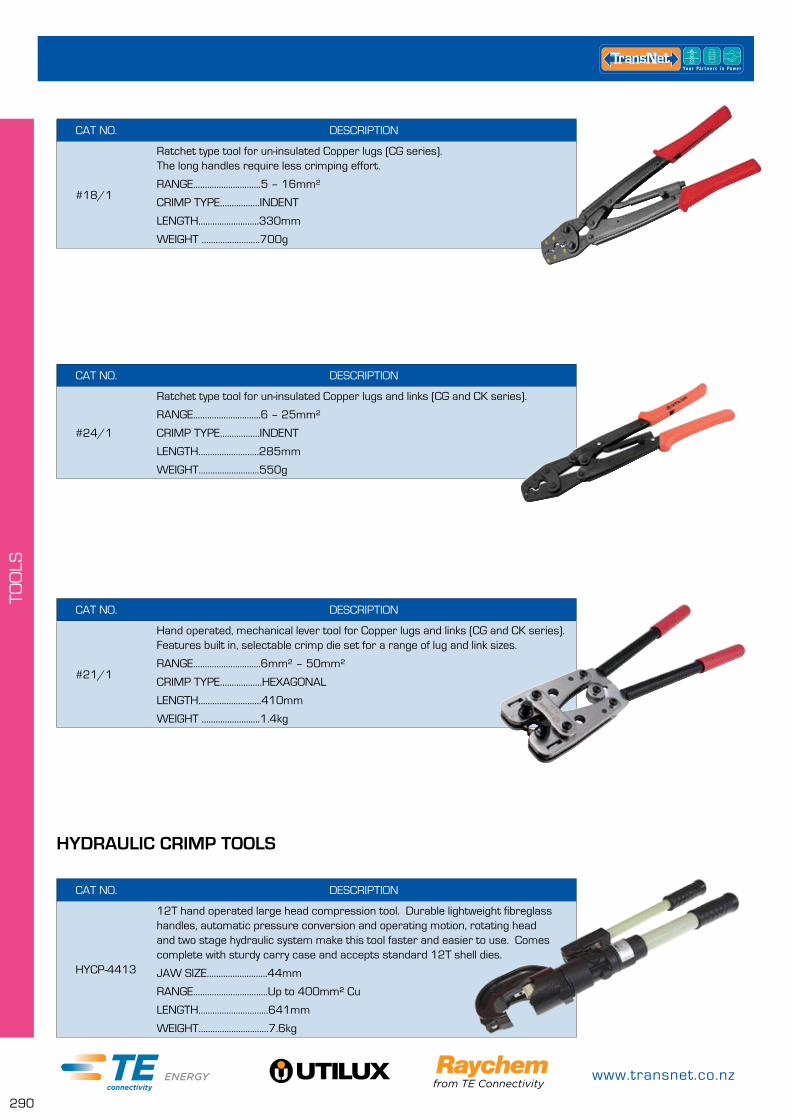
www.transnet.co.nz
290
TOO
LS
HYDRAULIC CRIMP TOOLS
CAT NO. DESCRIPTION
HYCP-4413
12T hand operated large head compression tool. Durable lightweight fibreglass handles, automatic pressure conversion and operating motion, rotating head and two stage hydraulic system make this tool faster and easier to use. Comes complete with sturdy carry case and accepts standard 12T shell dies.
JAW SIZE..........................44mm
RANGE................................Up to 400mm² Cu
LENGTH..............................641mm
WEIGHT..............................7.6kg
CAT NO. DESCRIPTION
#18/1
Ratchet type tool for un-insulated Copper lugs (CG series). The long handles require less crimping effort.
RANGE.............................5 – 16mm²
CRIMP TYPE.................INDENT
LENGTH..........................330mm
WEIGHT .........................700g
CAT NO. DESCRIPTION
#21/1
Hand operated, mechanical lever tool for Copper lugs and links (CG and CK series). Features built in, selectable crimp die set for a range of lug and link sizes.
RANGE.............................6mm² – 50mm²
CRIMP TYPE..................HEXAGONAL
LENGTH...........................410mm
WEIGHT .........................1.4kg
CAT NO. DESCRIPTION
#24/1
Ratchet type tool for un-insulated Copper lugs and links (CG and CK series).
RANGE.............................6 – 25mm²
CRIMP TYPE.................INDENT
LENGTH..........................285mm
WEIGHT..........................550g
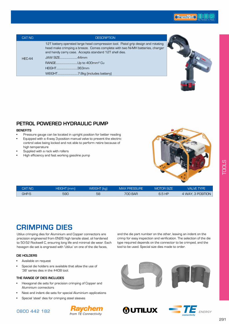
0800 442 182
291
TOO
LS
CAT NO. DESCRIPTION
HEC-44
12T battery operated large head compression tool. Pistol grip design and rotating head make crimping a breeze. Comes complete with two Ni-MH batteries, charger and handy carry case. Accepts standard 12T shell dies.
JAW SIZE..........................44mm
RANGE................................Up to 400mm² Cu
HEIGHT...............................363mm
WEIGHT..............................7.8kg (includes battery)
Utilux crimping dies for Aluminium and Copper connectors are precision engineered from EN26 high tensile steel, oil hardened to 50-52 Rockwell C, ensuring long life and minimal die wear. Each hexagon die set is engraved with ‘Utilux’ on one of the die faces,
DIE HOLDERS
• Available on request
• Special die holders are available that allow the use of ‘38’ series dies in the #408 tool.
THE RANGE OF DIES INCLUDES
• Hexagonal die sets for precision crimping of Copper and Aluminium connectors
• Nest and indent die sets for special Aluminium applications
• Special ‘steel’ dies for crimping steel sleeves
and the die part number on the other, leaving an indent on the crimp for easy inspection and verification. The selection of the die type required depends on the connector to be crimped, and the tool to be used. Special size dies made to order.
CRIMPING DIES
PETROL POWERED HYDRAULIC PUMP
CAT NO. HEIGHT (mm) WEIGHT (kg) MAX PRESSURE MOTOR SIZE VALVE TYPE
GHP-5 590 58 700 BAR 6.5 HP 4 WAY, 3 POSITION
BENEFITS• Pressure gauge can be located in upright position for better reading• Equipped with a 4-way 3-position manual valve to prevent the electric
control valve being locked and not able to perform retire because of high temperature
• Supplied with a rack with rollers• High efficiency and fast working gasoline pump
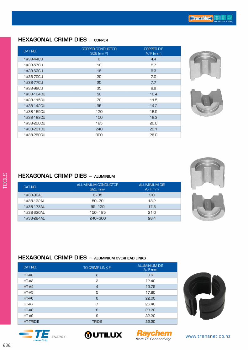
www.transnet.co.nz
292
TOO
LS
HEXAGONAL CRIMP DIES – ALUMINIUM OVERHEAD LINKS
CAT NO. TO CRIMP LINK # ALUMINIUM DIEA/F mm
HT-A2 2 9.6
HT-A3 3 12.40
HT-A4 4 13.75
HT-A5 5 17.90
HT-A6 6 22.00
HT-A7 7 25.40
HT-A8 8 28.20
HT-A9 9 32.20
HT-TRIDIE TRIDIE 32.20
HEXAGONAL CRIMP DIES – COPPER
CAT NO.COPPER CONDUCTOR
SIZE (mm²)COPPER DIEA/F (mm)
1#38-44CU 6 4.4
1#38-57CU 10 5.7
1#38-63CU 16 6.3
1#38-70CU 20 7.0
1#38-77CU 25 7.7
1#38-92CU 35 9.2
1#38-104CU 50 10.4
1#38-115CU 70 11.5
1#38-142CU 95 14.2
1#38-165CU 120 16.5
1#38-183CU 150 18.3
1#38-200CU 185 20.0
1#38-231CU 240 23.1
1#38-260CU 300 26.0
HEXAGONAL CRIMP DIES – ALUMINIUM
CAT NO.ALUMINIUM CONDUCTOR
SIZE mm²ALUMINIUM DIE
A/F mm
1#38-90AL 6–35 9.0
1#38-132AL 50–70 13.2
1#38-173AL 95–120 17.3
1#38-220AL 150–185 21.0
1#38-284AL 240–300 28.4
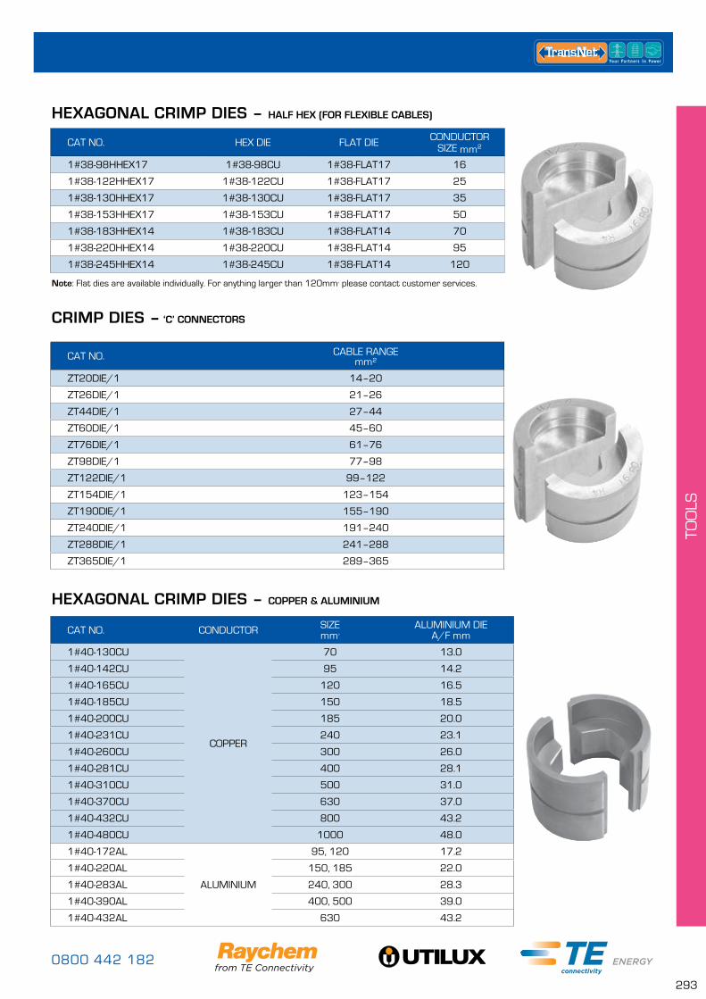
0800 442 182
293
TOO
LS
CAT NO. CONDUCTOR SIZEmm²
ALUMINIUM DIEA/F mm
1#40-130CU
COPPER
70 13.0
1#40-142CU 95 14.2
1#40-165CU 120 16.5
1#40-185CU 150 18.5
1#40-200CU 185 20.0
1#40-231CU 240 23.1
1#40-260CU 300 26.0
1#40-281CU 400 28.1
1#40-310CU 500 31.0
1#40-370CU 630 37.0
1#40-432CU 800 43.2
1#40-480CU 1000 48.0
1#40-172AL
ALUMINIUM
95, 120 17.2
1#40-220AL 150, 185 22.0
1#40-283AL 240, 300 28.3
1#40-390AL 400, 500 39.0
1#40-432AL 630 43.2
HEXAGONAL CRIMP DIES – COPPER & ALUMINIUM
HEXAGONAL CRIMP DIES – HALF HEX (FOR FLEXIBLE CABLES)
CRIMP DIES – ‘C’ CONNECTORS
CAT NO. HEX DIE FLAT DIE CONDUCTOR SIZE mm²
1#38-98HHEX17 1#38-98CU 1#38-FLAT17 16
1#38-122HHEX17 1#38-122CU 1#38-FLAT17 25
1#38-130HHEX17 1#38-130CU 1#38-FLAT17 35
1#38-153HHEX17 1#38-153CU 1#38-FLAT17 50
1#38-183HHEX14 1#38-183CU 1#38-FLAT14 70
1#38-220HHEX14 1#38-220CU 1#38-FLAT14 95
1#38-245HHEX14 1#38-245CU 1#38-FLAT14 120
CAT NO. CABLE RANGEmm²
ZT20DIE/1 14–20
ZT26DIE/1 21–26
ZT44DIE/1 27–44
ZT60DIE/1 45–60
ZT76DIE/1 61–76
ZT98DIE/1 77–98
ZT122DIE/1 99–122
ZT154DIE/1 123–154
ZT190DIE/1 155–190
ZT240DIE/1 191–240
ZT288DIE/1 241–288
ZT365DIE/1 289–365
Note: Flat dies are available individually. For anything larger than 120mm² please contact customer services.
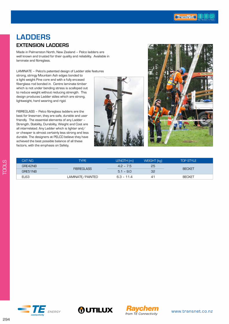
www.transnet.co.nz
294
TOO
LS
CAT NO. TYPE LENGTH (m) WEIGHT (kg) TOP STYLE
GRE42NBFIBREGLASS
4.2 – 7.5 25BECKET
GRE51NB 5.1 – 9.0 32
EL63 LAMINATE/PAINTED 6.3 – 11.4 41 BECKET
EXTENSION LADDERSLADDERS
Made in Palmerston North, New Zealand – Pelco ladders are well known and trusted for their quality and reliability. Available in laminate and fibreglass.
LAMINATE – Pelco's patented design of Ladder stile features strong, stringy Mountain Ash edges bonded to a light weight Pine core and with a fully encased fiberglass rod bonded in. Centre laminate timber which is not under bending stress is scalloped out to reduce weight without reducing strength. This design produces Ladder stiles which are strong, lightweight, hard wearing and rigid.
FIBREGLASS – Pelco fibreglass ladders are the best for linesmen, they are safe, durable and user friendly. The essential elements of any Ladder – Strength, Stability, Durability, Weight and Cost are all interrelated. Any Ladder which is lighter and/or cheaper is almost certainly less strong and less durable. The designers at PELCO believe they have achieved the best possible balance of all these factors, with the emphasis on Safety.
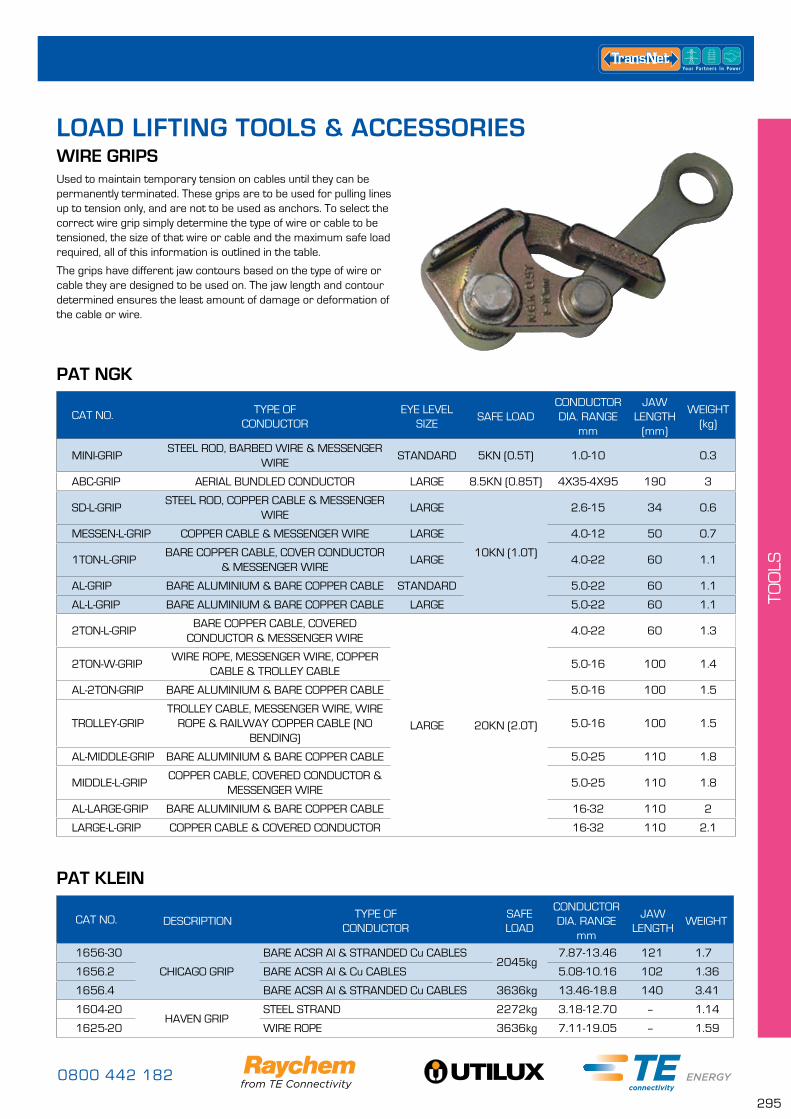
0800 442 182
295
TOO
LS
WIRE GRIPS
PAT NGK
Used to maintain temporary tension on cables until they can be permanently terminated. These grips are to be used for pulling lines up to tension only, and are not to be used as anchors. To select the correct wire grip simply determine the type of wire or cable to be tensioned, the size of that wire or cable and the maximum safe load required, all of this information is outlined in the table.
The grips have different jaw contours based on the type of wire or cable they are designed to be used on. The jaw length and contour determined ensures the least amount of damage or deformation of the cable or wire.
CAT NO. TYPE OF CONDUCTOR
EYE LEVEL SIZE
SAFE LOADCONDUCTOR DIA. RANGE
mm
JAW LENGTH
(mm)
WEIGHT(kg)
MINI-GRIPSTEEL ROD, BARBED WIRE & MESSENGER
WIRESTANDARD 5KN (0.5T) 1.0-10 0.3
ABC-GRIP AERIAL BUNDLED CONDUCTOR LARGE 8.5KN (0.85T) 4X35-4X95 190 3
SD-L-GRIPSTEEL ROD, COPPER CABLE & MESSENGER
WIRELARGE
10KN (1.0T)
2.6-15 34 0.6
MESSEN-L-GRIP COPPER CABLE & MESSENGER WIRE LARGE 4.0-12 50 0.7
1TON-L-GRIPBARE COPPER CABLE, COVER CONDUCTOR
& MESSENGER WIRELARGE 4.0-22 60 1.1
AL-GRIP BARE ALUMINIUM & BARE COPPER CABLE STANDARD 5.0-22 60 1.1
AL-L-GRIP BARE ALUMINIUM & BARE COPPER CABLE LARGE 5.0-22 60 1.1
2TON-L-GRIPBARE COPPER CABLE, COVERED
CONDUCTOR & MESSENGER WIRE
LARGE 20KN (2.0T)
4.0-22 60 1.3
2TON-W-GRIPWIRE ROPE, MESSENGER WIRE, COPPER
CABLE & TROLLEY CABLE5.0-16 100 1.4
AL-2TON-GRIP BARE ALUMINIUM & BARE COPPER CABLE 5.0-16 100 1.5
TROLLEY-GRIPTROLLEY CABLE, MESSENGER WIRE, WIRE
ROPE & RAILWAY COPPER CABLE (NO BENDING)
5.0-16 100 1.5
AL-MIDDLE-GRIP BARE ALUMINIUM & BARE COPPER CABLE 5.0-25 110 1.8
MIDDLE-L-GRIPCOPPER CABLE, COVERED CONDUCTOR &
MESSENGER WIRE5.0-25 110 1.8
AL-LARGE-GRIP BARE ALUMINIUM & BARE COPPER CABLE 16-32 110 2
LARGE-L-GRIP COPPER CABLE & COVERED CONDUCTOR 16-32 110 2.1
PAT KLEIN
CAT NO. DESCRIPTIONTYPE OF
CONDUCTORSAFE LOAD
CONDUCTOR DIA. RANGE
mm
JAW LENGTH
WEIGHT
1656-30
CHICAGO GRIP
BARE ACSR Al & STRANDED Cu CABLES2045kg
7.87-13.46 121 1.7
1656.2 BARE ACSR Al & Cu CABLES 5.08-10.16 102 1.36
1656.4 BARE ACSR Al & STRANDED Cu CABLES 3636kg 13.46-18.8 140 3.41
1604-20HAVEN GRIP
STEEL STRAND 2272kg 3.18-12.70 – 1.14
1625-20 WIRE ROPE 3636kg 7.11-19.05 – 1.59
LOAD LIFTING TOOLS & ACCESSORIES
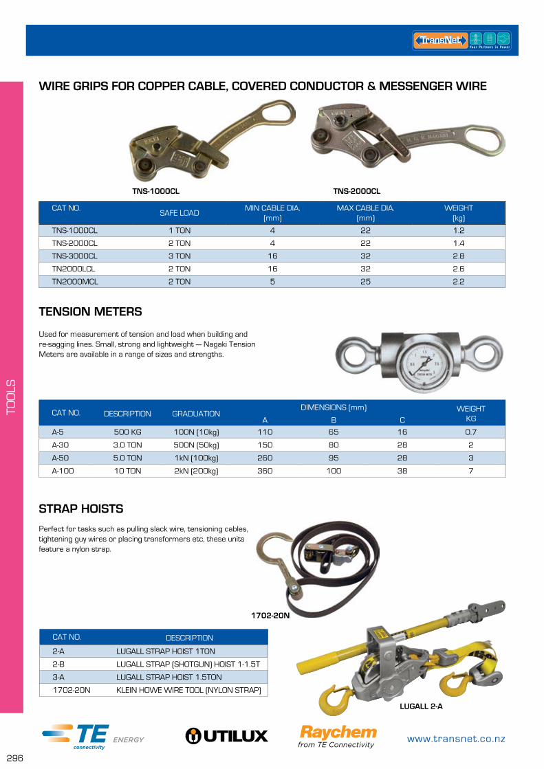
www.transnet.co.nz
296
TOO
LS
CAT NO.SAFE LOAD
MIN CABLE DIA. (mm)
MAX CABLE DIA. (mm)
WEIGHT (kg)
TNS-1000CL 1 TON 4 22 1.2
TNS-2000CL 2 TON 4 22 1.4
TNS-3000CL 3 TON 16 32 2.8
TN2000LCL 2 TON 16 32 2.6
TN2000MCL 2 TON 5 25 2.2
WIRE GRIPS FOR COPPER CABLE, COVERED CONDUCTOR & MESSENGER WIRE
TNS-1000CL TNS-2000CL
TENSION METERS
STRAP HOISTS
CAT NO. DESCRIPTION GRADUATIONDIMENSIONS (mm) WEIGHT
KGA B C
A-5 500 KG 100N (10kg) 110 65 16 0.7
A-30 3.0 TON 500N (50kg) 150 80 28 2
A-50 5.0 TON 1kN (100kg) 260 95 28 3
A-100 10 TON 2kN (200kg) 360 100 38 7
CAT NO. DESCRIPTION
2-A LUGALL STRAP HOIST 1TON
2-B LUGALL STRAP (SHOTGUN) HOIST 1-1.5T
3-A LUGALL STRAP HOIST 1.5TON
1702-20N KLEIN HOWE WIRE TOOL (NYLON STRAP)
Used for measurement of tension and load when building and re-sagging lines. Small, strong and lightweight — Nagaki Tension Meters are available in a range of sizes and strengths.
Perfect for tasks such as pulling slack wire, tensioning cables, tightening guy wires or placing transformers etc, these units feature a nylon strap.
1702-20N
LUGALL 2-A
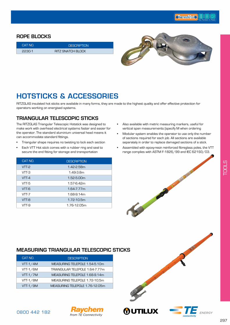
0800 442 182
297
TOO
LS
ROPE BLOCKS
CAT NO. DESCRIPTION
2230-1 RITZ SNATCH BLOCK
RITZGLAS insulated hot sticks are available in many forms, they are made to the highest quality and offer effective protection for operators working on energised systems.
TRIANGULAR TELESCOPIC STICKSThe RITZGLAS Triangular Telescopic Hotstick was designed to make work with overhead electrical systems faster and easier for the operator. The standard aluminium universal head means it can accommodate standard fittings.
• Triangular shape requires no twisting to lock each section
• Each VTT Hot stick comes with a rubber ring and seal to secure the end fitting for storage and transportation
CAT NO. DESCRIPTION
VTT-2 1.42-2.58m
VTT-3 1.49-3.8m
VTT-4 1.52-5.00m
VTT-5 1.57-6.42m
VTT-6 1.64-7.77m
VTT-7 1.68-9.14m
VTT-8 1.72-10.5m
VTT-9 1.76-12.05m
• Also available with metric measuring markers, useful for vertical span measurements (specify M when ordering
• Modular system enables the operator to use only the number of sections required for each job. All sections are available separately in order to replace damaged sections of a stick.
• Assembled with epoxy-resin reinforced fibreglass poles, the VTT range complies with ASTM F-1826/99 and IEC 62193/03.
HOTSTICKS & ACCESSORIES
MEASURING TRIANGULAR TELESCOPIC STICKSCAT NO. DESCRIPTION
VTT-1/4M MEASURING TELEPOLE 1.54-5.10m
VTT-1/6M TRIANGULAR TELEPOLE 1.64-7.77m
VTT-1/7M MEASURING TELEPOLE 1.68-9.14m
VTT-1/8M MEASURING TELEPOLE 1.72-10.5m
VTT-1/9M MEASURING TELEPOLE 1.76-12.05m
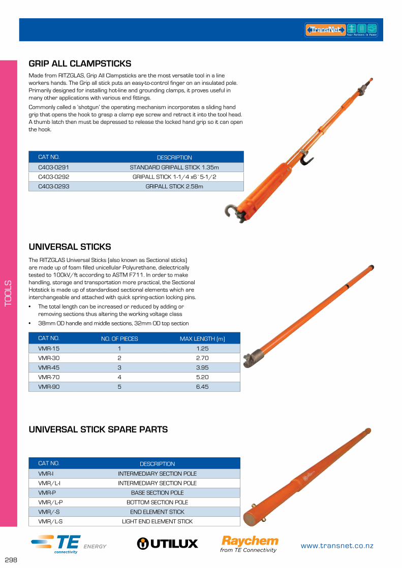
www.transnet.co.nz
298
TOO
LS
GRIP ALL CLAMPSTICKS
CAT NO. DESCRIPTION
C403-0291 STANDARD GRIPALL STICK 1.35m
C403-0292 GRIPALL STICK 1-1/4 x6`5-1/2
C403-0293 GRIPALL STICK 2.58m
Made from RITZGLAS, Grip All Clampsticks are the most versatile tool in a line workers hands. The Grip all stick puts an easy-to-control finger on an insulated pole. Primarily designed for installing hot-line and grounding clamps, it proves useful in many other applications with various end fittings.
Commonly called a ‘shotgun’ the operating mechanism incorporates a sliding hand grip that opens the hook to grasp a clamp eye screw and retract it into the tool head. A thumb latch then must be depressed to release the locked hand grip so it can open the hook.
UNIVERSAL STICKS
UNIVERSAL STICK SPARE PARTS
CAT NO. NO. OF PIECES MAX LENGTH (m)
VMR-15 1 1.25
VMR-30 2 2.70
VMR-45 3 3.95
VMR-70 4 5.20
VMR-90 5 6.45
CAT NO. DESCRIPTION
VMR-I INTERMEDIARY SECTION POLE
VMR/L-I INTERMEDIARY SECTION POLE
VMR-P BASE SECTION POLE
VMR/L-P BOTTOM SECTION POLE
VMR/-S END ELEMENT STICK
VMR/L-S LIGHT END ELEMENT STICK
The RITZGLAS Universal Sticks (also known as Sectional sticks) are made up of foam filled unicellular Polyurethane, dielectrically tested to 100kV/ft according to ASTM F711. In order to make handling, storage and transportation more practical, the Sectional Hotstick is made up of standardised sectional elements which are interchangeable and attached with quick spring-action locking pins.
• The total length can be increased or reduced by adding or removing sections thus altering the working voltage class
• 38mm OD handle and middle sections, 32mm OD top section
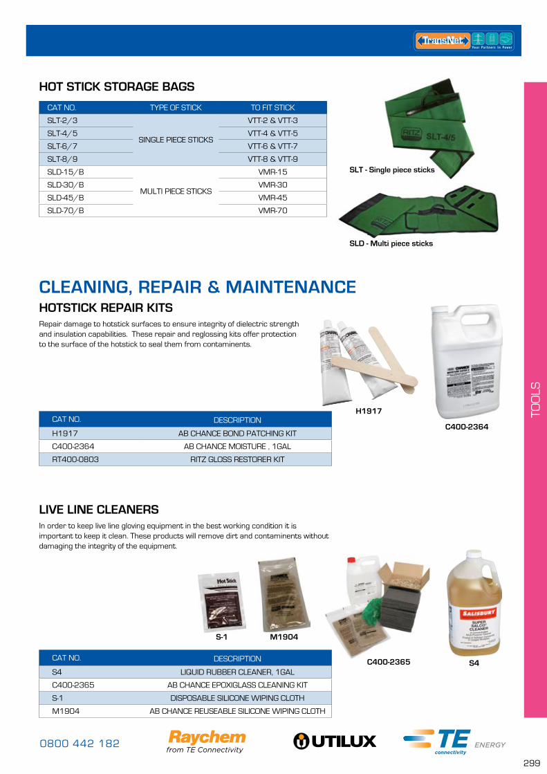
0800 442 182
299
TOO
LS
HOTSTICK REPAIR KITS
LIVE LINE CLEANERS
CAT NO. DESCRIPTION
H1917 AB CHANCE BOND PATCHING KIT
C400-2364 AB CHANCE MOISTURE , 1GAL
RT400-0803 RITZ GLOSS RESTORER KIT
CAT NO. DESCRIPTION
S4 LIQUID RUBBER CLEANER, 1GAL
C400-2365 AB CHANCE EPOXIGLASS CLEANING KIT
S-1 DISPOSABLE SILICONE WIPING CLOTH
M1904 AB CHANCE REUSEABLE SILICONE WIPING CLOTH
Repair damage to hotstick surfaces to ensure integrity of dielectric strength and insulation capabilities. These repair and reglossing kits offer protection to the surface of the hotstick to seal them from contaminents.
In order to keep live line gloving equipment in the best working condition it is important to keep it clean. These products will remove dirt and contaminents without damaging the integrity of the equipment.
HOT STICK STORAGE BAGS
CAT NO. TYPE OF STICK TO FIT STICK
SLT-2/3
SINGLE PIECE STICKS
VTT-2 & VTT-3
SLT-4/5 VTT-4 & VTT-5
SLT-6/7 VTT-6 & VTT-7
SLT-8/9 VTT-8 & VTT-9
SLD-15/B
MULTI PIECE STICKS
VMR-15
SLD-30/B VMR-30
SLD-45/B VMR-45
SLD-70/B VMR-70
SLT - Single piece sticks
SLD - Multi piece sticks
CLEANING, REPAIR & MAINTENANCE
H1917
C400-2364
S4C400-2365
S-1 M1904
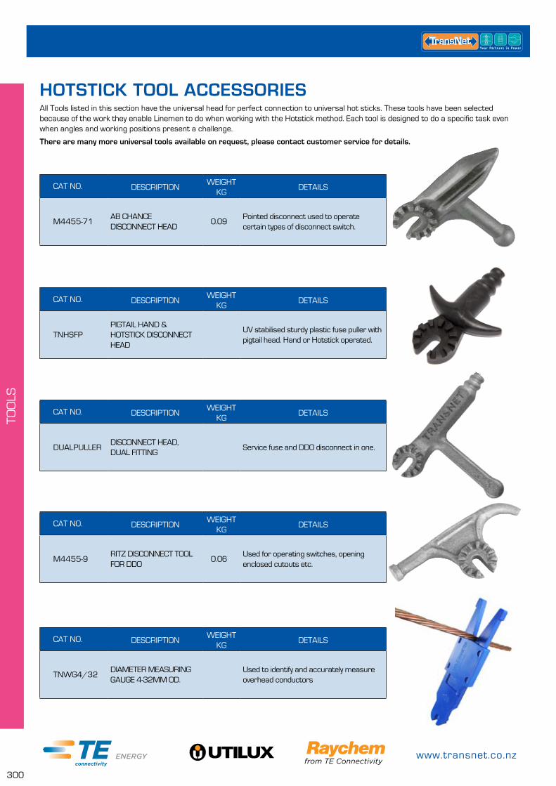
www.transnet.co.nz
300
TOO
LS
All Tools listed in this section have the universal head for perfect connection to universal hot sticks. These tools have been selected because of the work they enable Linemen to do when working with the Hotstick method. Each tool is designed to do a specific task even when angles and working positions present a challenge.
There are many more universal tools available on request, please contact customer service for details.
HOTSTICK TOOL ACCESSORIES
CAT NO. DESCRIPTIONWEIGHT
KGDETAILS
M4455-71AB CHANCE DISCONNECT HEAD
0.09Pointed disconnect used to operate certain types of disconnect switch.
CAT NO. DESCRIPTIONWEIGHT
KGDETAILS
TNHSFPPIGTAIL HAND & HOTSTICK DISCONNECT HEAD
UV stabilised sturdy plastic fuse puller with pigtail head. Hand or Hotstick operated.
CAT NO. DESCRIPTIONWEIGHT
KGDETAILS
DUALPULLERDISCONNECT HEAD, DUAL FITTING
Service fuse and DDO disconnect in one.
CAT NO. DESCRIPTIONWEIGHT
KGDETAILS
M4455-9RITZ DISCONNECT TOOL FOR DDO
0.06Used for operating switches, opening enclosed cutouts etc.
CAT NO. DESCRIPTIONWEIGHT
KGDETAILS
TNWG4/32DIAMETER MEASURING GAUGE 4-32MM OD.
Used to identify and accurately measure overhead conductors
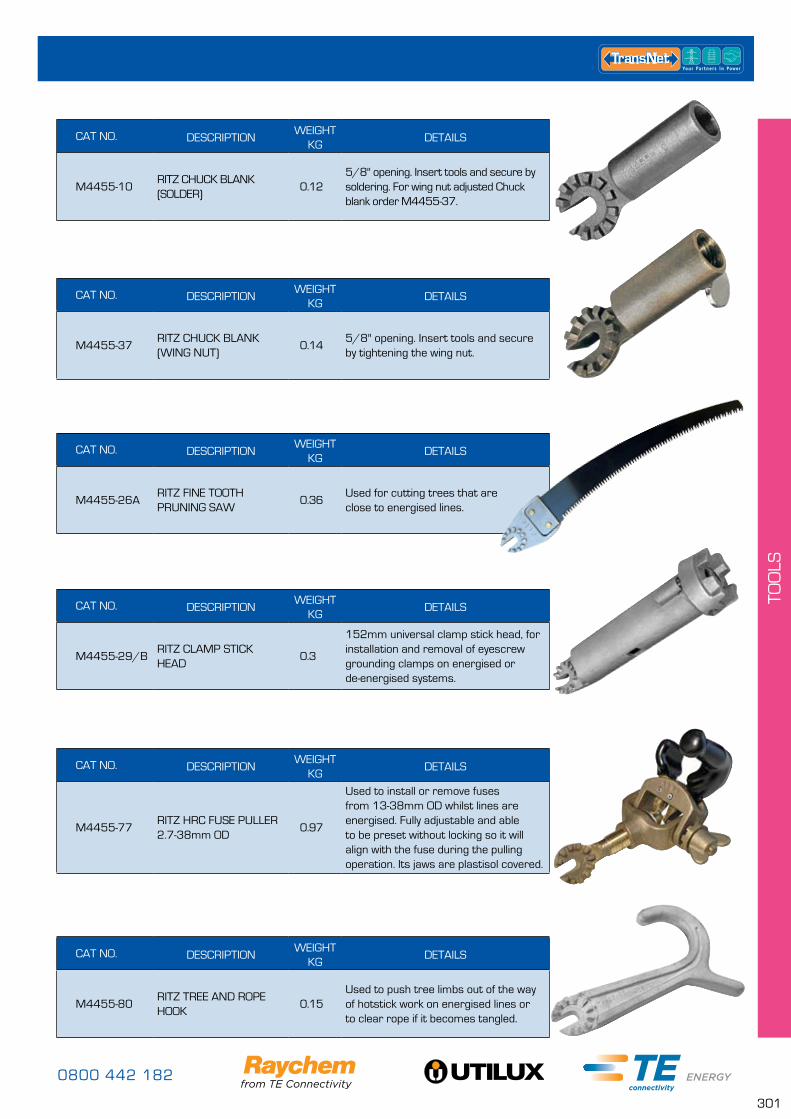
0800 442 182
301
TOO
LS
CAT NO. DESCRIPTIONWEIGHT
KGDETAILS
M4455-10RITZ CHUCK BLANK (SOLDER)
0.125/8" opening. Insert tools and secure by soldering. For wing nut adjusted Chuck blank order M4455-37.
CAT NO. DESCRIPTIONWEIGHT
KGDETAILS
M4455-37RITZ CHUCK BLANK (WING NUT)
0.145/8" opening. Insert tools and secure by tightening the wing nut.
CAT NO. DESCRIPTIONWEIGHT
KGDETAILS
M4455-26ARITZ FINE TOOTH PRUNING SAW
0.36Used for cutting trees that are close to energised lines.
CAT NO. DESCRIPTIONWEIGHT
KGDETAILS
M4455-29/BRITZ CLAMP STICK HEAD
0.3
152mm universal clamp stick head, for installation and removal of eyescrew grounding clamps on energised or de-energised systems.
CAT NO. DESCRIPTIONWEIGHT
KGDETAILS
M4455-77RITZ HRC FUSE PULLER 2.7-38mm OD
0.97
Used to install or remove fuses from 13-38mm OD whilst lines are energised. Fully adjustable and able to be preset without locking so it will align with the fuse during the pulling operation. Its jaws are plastisol covered.
CAT NO. DESCRIPTIONWEIGHT
KGDETAILS
M4455-80RITZ TREE AND ROPE HOOK
0.15Used to push tree limbs out of the way of hotstick work on energised lines or to clear rope if it becomes tangled.
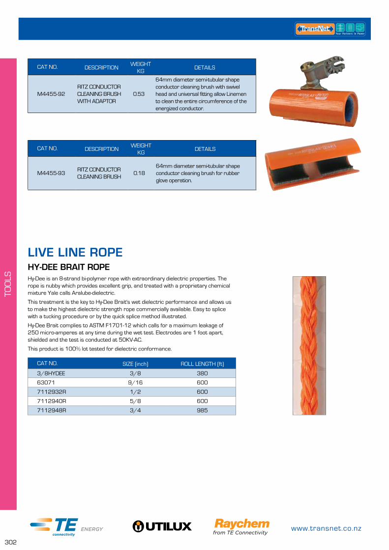
www.transnet.co.nz
302
TOO
LS
CAT NO. DESCRIPTIONWEIGHT
KGDETAILS
M4455-92RITZ CONDUCTOR CLEANING BRUSH WITH ADAPTOR
0.53
64mm diameter semi-tubular shape conductor cleaning brush with swivel head and universal fitting allow Linemen to clean the entire circumference of the energized conductor.
CAT NO. DESCRIPTIONWEIGHT
KGDETAILS
M4455-93RITZ CONDUCTOR CLEANING BRUSH
0.1864mm diameter semi-tubular shape conductor cleaning brush for rubber glove operation.
HY-DEE BRAIT ROPE
CAT NO. SIZE (inch) ROLL LENGTH (ft)
3/8HYDEE 3/8 380
63071 9/16 600
7112932R 1/2 600
7112940R 5/8 600
7112948R 3/4 985
Hy-Dee is an 8-strand bi-polymer rope with extraordinary dielectric properties. The rope is nubby which provides excellent grip, and treated with a proprietary chemical mixture Yale calls Aralube-dielectric.
This treatment is the key to Hy-Dee Brait's wet dielectric performance and allows us to make the highest dielectric strength rope commercially available. Easy to splice with a tucking procedure or by the quick splice method illustrated.
Hy-Dee Brait complies to ASTM F1701-12 which calls for a maximum leakage of 250 micro-amperes at any time during the wet test. Electrodes are 1 foot apart, shielded and the test is conducted at 50KV-AC.
This product is 100% lot tested for dielectric conformance.
LIVE LINE ROPE
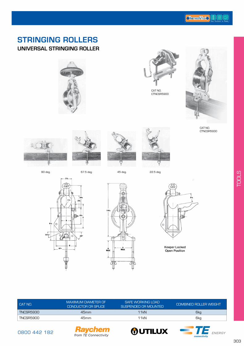
0800 442 182
303
TOO
LS
UNIVERSAL STRINGING ROLLER
CAT NO.MAXIMUM DIAMETER OF CONDUCTOR OR SPLICE
SAFE WORKING LOAD SUSPENDED OR MOUNTED
COMBINED ROLLER WEIGHT
TNCSR5930 45mm 11kN 6kg
TNCSR5900 45mm 11kN 6kg
CAT NO.CTNCSR5930
90 deg. 67.5 deg. 45 deg. 22.5 deg
.
CAT NO.CTNCSR5900
STRINGING ROLLERS
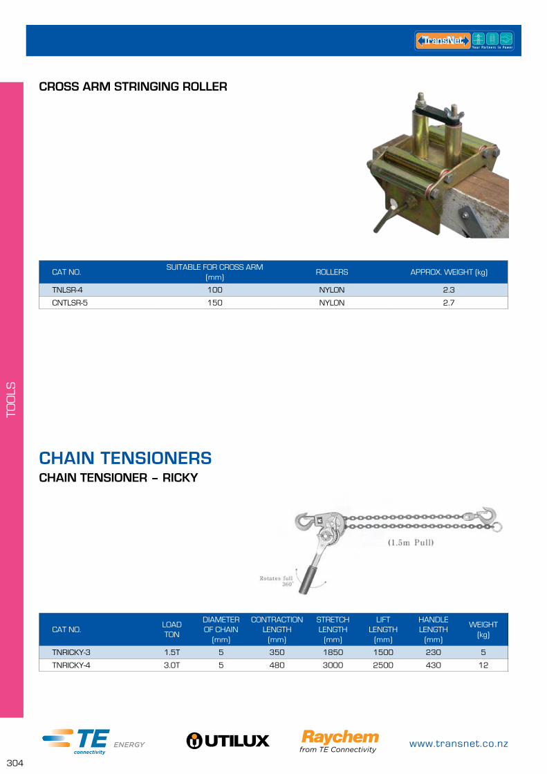
www.transnet.co.nz
304
TOO
LS
CROSS ARM STRINGING ROLLER
CHAIN TENSIONER – RICKY
CAT NO.SUITABLE FOR CROSS ARM
(mm)ROLLERS APPROX. WEIGHT (kg)
TNLSR-4 100 NYLON 2.3
CNTLSR-5 150 NYLON 2.7
CAT NO.LOAD TON
DIAMETER OF CHAIN
(mm)
CONTRACTION LENGTH
(mm)
STRETCH LENGTH
(mm)
LIFT LENGTH
(mm)
HANDLE LENGTH
(mm)
WEIGHT (kg)
TNRICKY-3 1.5T 5 350 1850 1500 230 5
TNRICKY-4 3.0T 5 480 3000 2500 430 12
CHAIN TENSIONERS
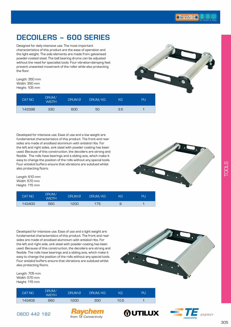
0800 442 182
305
TOO
LS
CAT NO.DRUM/WIDTH
DRUM Ø DRUM/KG KG PU
143398 330 600 50 3.5 1
CAT NO.DRUM/WIDTH
DRUM Ø DRUM/KG KG PU
143400 560 1200 175 9 1
CAT NO.DRUM/WIDTH
DRUM Ø DRUM/KG KG PU
143402 660 1200 300 10.5 1
Designed for daily intensive use. The most important characteristics of this product are the ease of operation and the light weight. The side elements are made from galvanised powder-coated steel. The ball bearing drums can be adjusted without the need for specialist tools. Four vibration-damping feet prevent unwanted movement of the roller while also protecting the floor.
Length: 350 mmWidth: 350 mmHeight: 105 mm
Developed for intensive use. Ease of use and a low weight are fundamental characteristics of this product. The front and rear sides are made of anodised aluminium with antiskid ribs. For the left and right sides, sink steel with powder coating has been used. Because of this construction, the decoilers are strong and flexible. The rolls have bearings and a sliding axis, which make it easy to change the position of the rolls without any special tools. Four antiskid buffers ensure that vibrations are subdued whilst also protecting floors.
Length: 610 mmWidth: 570 mmHeight: 115 mm
Developed for intensive use. Ease of use and a light weight are fundamental characteristics of this product. The front and rear sides are made of anodised aluminium with antiskid ribs. For the left and right side, sink steel with powder coating has been used. Because of this construction, the decoilers are strong and flexible. The rolls have bearings and a sliding axis, which make it easy to change the position of the rolls without any special tools. Four antiskid buffers ensure that vibrations are subdued whilst also protecting floors.
Length: 705 mmWidth: 570 mmHeight: 115 mm
DECOILERS – 600 SERIES

www.transnet.co.nz
306
TOO
LS
TEMPORARY LIGHTS
The perfect portable work light. Available in 10W and 20W this rechargable battery powered LED Floodlight on a sturdy stand and suction cup attachment for awkward places is a must have.
FEATURES• 1200 Light beam
• 5000K Colour Temperature/Ra75
• 85~265V AC NZ power plug & 12–24V DC car plug chargers included
• 4hr Battery run time
• Rechargable Li-Ion battery
• IP65 rated
CAT NO. LUMENS POWER SUPPLY VOLTAGE
LEDFL-PORTABLE3DC 3x900 3x10W 9-30V DC
LEDFL-PORTABLE3ACDC 3x900 3x10W 85~265V AC & 9-30V DC
LEDFL-PORTABLE3AC 3x900 3x10W 85~265C AC
Engineered to withstand the inevitable bumps and knocks that portable lights endure. AC, DC and AC/DC versions available, the AC/DC version comes complete with the power supply kit so you can power it from your car, truck, or connect it direct to a battery or plug it into the main power supply. All models come in a handy carry bag.
FEATURES• Telescopic stand to offer a range of working heights, approximately
800mm–1600mm
• Easy to assemble and put away, fits into small storage areas
• Lights and lead operating at a safe voltage at all times
• Long 12m lead
• 12/24V DC or 230V AC/DC (depending on the model)
• Sturdy canvas storage bag, 770x250x200mm
• Cool running temperature
BATTERY POWERED LED FLOOD LIGHTS WITH STAND
PORTABLE LIGHT STANDS – 10W LEDS
CAT NO. BASE MOUNT LUMENS POWER RUN TIME*
LEDFL-10WBATTSTAND
900 10W 4hrs
LEDFL-20WBATT 1800 20W 4hrs
LEDFL-10WBATTSK SUCTION CUP & STAND 900 10W 4hrs
LEDFL-10WBATTSK
LEDFL-10WBATT
LEDFL-20WBATT

0800 442 182
307
TOO
LS
CAT NO. LUMENS POWER SUPPLY VOLTAGE
LEDILS-2500 2x3600 2x40W 230V AC
CAT NO. LUMENS POWER SUPPLY VOLTAGE
LEDILS-5000KIT 36,000 400W 230V AC OR 12V DC
This industrial light stand (ILS) is engineered to cater for the commercial user where durability is of key importance.
FEATURES• Telescopic stand to offer a range of working heights, approximately
1250mm–2500mm
• Easy to assemble and put away, fits into small storage areas
• Long 12m lead
• Power source 230V AC
• Cool running temperature
*DC model available on special order
PORTABLE LIGHT STANDS – 40W LEDS
FULLY RETRACTED HEIGHT 1.6M
FULLY EXTENDED HEIGHT 5.0M
This light kit is the epitomy of temporary light stands. With an air extendable hydraulic telescopic stand the light can be positioned up to 5m above the work site. All the components to run this light (AC and DC) are included in the kit.
SPECIFICATIONS:• IP65 Rating
• 1.6m up to 5m when extended
• LxWxH when packed in case = 800x520x320mm
• Stand Weight = 17.85kg
• Packed in Case Weight = 32.85kg
KIT CONTENTS:• 400W LED light fitting
• Air extendable light stand
• Bicycle track pump
• Battery leads
• 400W inverter
• Storage bag for stand
• Tough plastic carry case
PORTABLE LIGHT STANDS – 400W LEDS
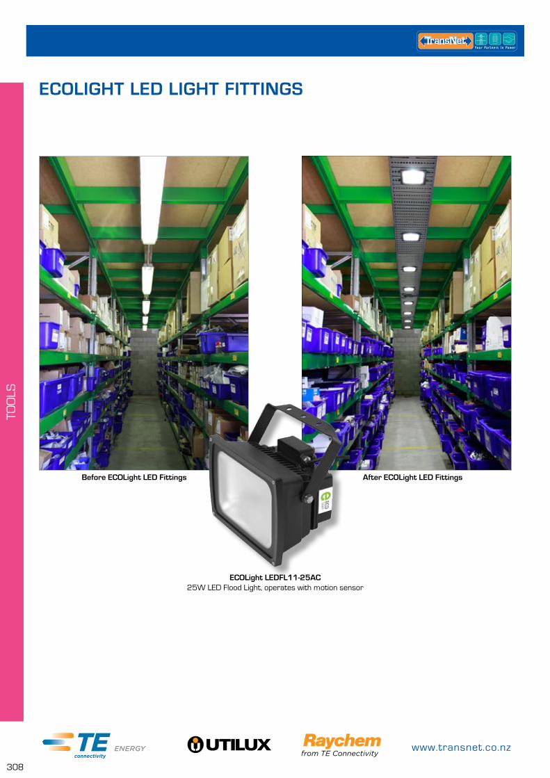
www.transnet.co.nz
308
TOO
LS
ECOLIGHT LED LIGHT FITTINGS
Before ECOLight LED Fittings
ECOLight LEDFL11-25AC25W LED Flood Light, operates with motion sensor
After ECOLight LED Fittings
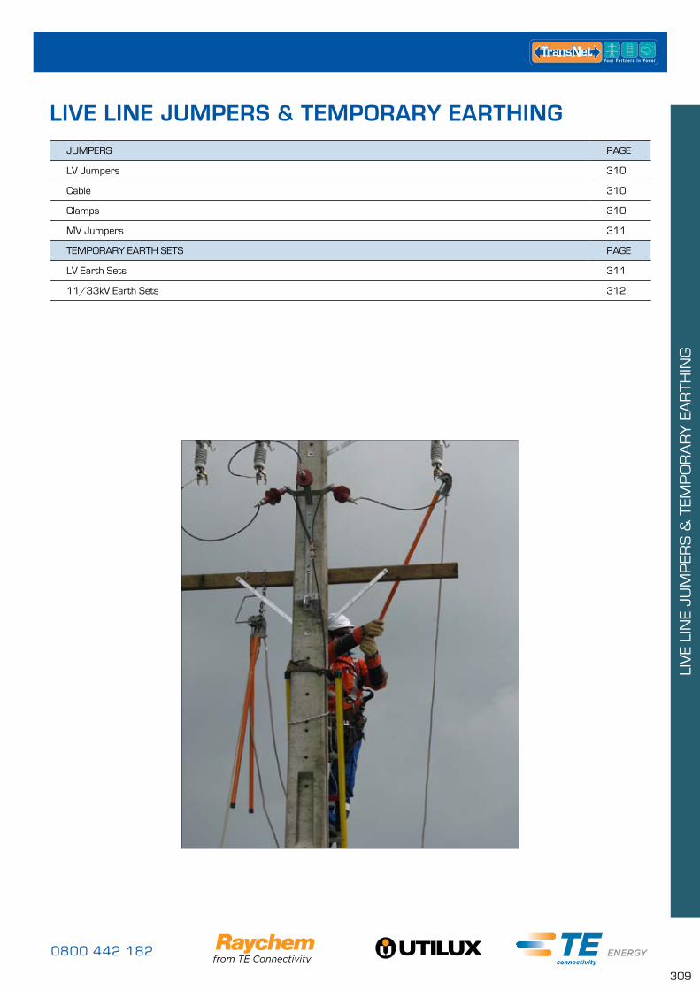
0800 442 182
309
LIV
E LI
NE
JUM
PER
S &
TEM
PO
RA
RY
EA
RTH
ING
JUMPERS PAGE
LV Jumpers 310
Cable 310
Clamps 310
MV Jumpers 311
TEMPORARY EARTH SETS PAGE
LV Earth Sets 311
11/33kV Earth Sets 312
LIVE LINE JUMPERS & TEMPORARY EARTHING
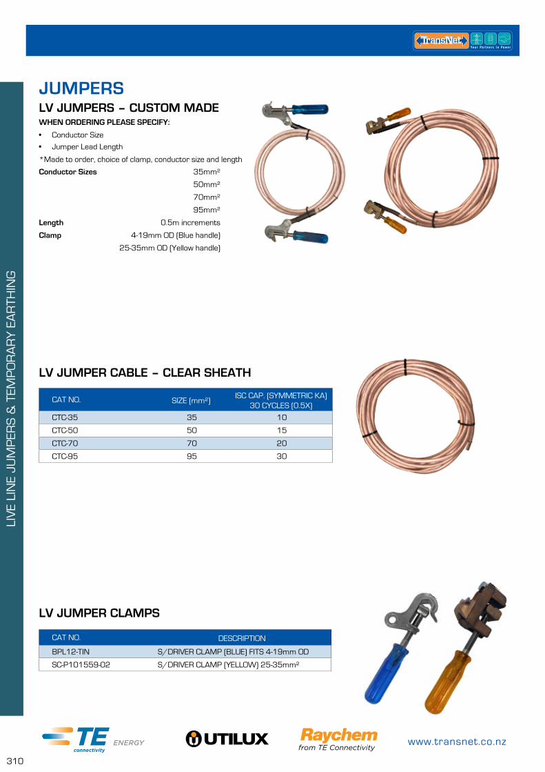
www.transnet.co.nz
310
LIV
E LI
NE
JUM
PER
S &
TEM
PO
RA
RY
EA
RTH
ING
LV JUMPERS – CUSTOM MADE
CAT NO. DESCRIPTION
BPL12-TIN S/DRIVER CLAMP (BLUE) FITS 4-19mm OD
SC-P101559-02 S/DRIVER CLAMP (YELLOW) 25-35mm²
CAT NO. SIZE (mm²)ISC CAP. (SYMMETRIC KA)
30 CYCLES (0.5X)
CTC-35 35 10
CTC-50 50 15
CTC-70 70 20
CTC-95 95 30
WHEN ORDERING PLEASE SPECIFY:
• Conductor Size
• Jumper Lead Length
*Made to order, choice of clamp, conductor size and length
JUMPERS
Conductor Sizes 35mm²
50mm²
70mm²
95mm²
Length 0.5m increments
Clamp 4-19mm OD (Blue handle)
25-35mm OD (Yellow handle)
LV JUMPER CLAMPS
LV JUMPER CABLE – CLEAR SHEATH
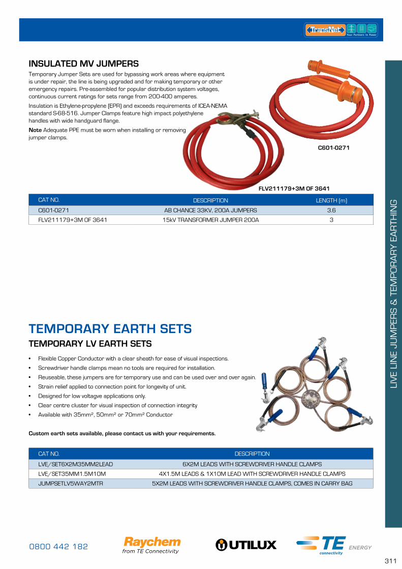
0800 442 182
311
LIV
E LI
NE
JUM
PER
S &
TEM
PO
RA
RY
EA
RTH
ING
TEMPORARY EARTH SETSTEMPORARY LV EARTH SETS
• Flexible Copper Conductor with a clear sheath for ease of visual inspections.
• Screwdriver handle clamps mean no tools are required for installation.
• Reuseable, these jumpers are for temporary use and can be used over and over again.
• Strain relief applied to connection point for longevity of unit.
• Designed for low voltagve applications only.
• Clear centre cluster for visual inspection of connection integrity
• Available with 35mm², 50mm² or 70mm² Conductor
Custom earth sets available, please contact us with your requirements.
CAT NO. DESCRIPTION
LVE/SET6X2M35MM2LEAD 6X2M LEADS WITH SCREWDRIVER HANDLE CLAMPS
LVE/SET35MM1.5M10M 4X1.5M LEADS & 1X10M LEAD WITH SCREWDRIVER HANDLE CLAMPS
JUMPSETLV5WAY2MTR 5X2M LEADS WITH SCREWDRIVER HANDLE CLAMPS, COMES IN CARRY BAG
INSULATED MV JUMPERS
CAT NO. DESCRIPTION LENGTH (m)
C601-0271 AB CHANCE 33KV, 200A JUMPERS 3.6
FLV211179+3M OF 3641 15kV TRANSFORMER JUMPER 200A 3
Temporary Jumper Sets are used for bypassing work areas where equipment is under repair, the line is being upgraded and for making temporary or other emergency repairs. Pre-assembled for popular distribution system voltages, continuous current ratings for sets range from 200-400 amperes.
Insulation is Ethylene-propylene (EPR) and exceeds requirements of ICEA-NEMA standard S-68-516. Jumper Clamps feature high impact polyethylene handles with wide handguard flange.
Note Adequate PPE must be worn when installing or removing jumper clamps.
C601-0271
FLV211179+3M OF 3641
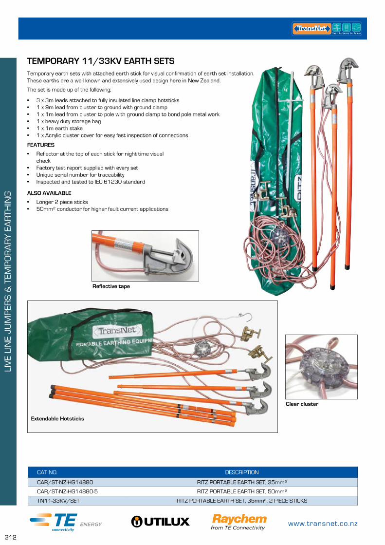
www.transnet.co.nz
312
LIV
E LI
NE
JUM
PER
S &
TEM
PO
RA
RY
EA
RTH
ING
TEMPORARY 11/33KV EARTH SETSTemporary earth sets with attached earth stick for visual confirmation of earth set installation. These earths are a well known and extensively used design here in New Zealand.
The set is made up of the following;
• 3 x 3m leads attached to fully insulated line clamp hotsticks• 1 x 9m lead from cluster to ground with ground clamp• 1 x 1m lead from cluster to pole with ground clamp to bond pole metal work• 1 x heavy duty storage bag• 1 x 1m earth stake• 1 x Acrylic cluster cover for easy fast inspection of connections
FEATURES
• Reflector at the top of each stick for night time visual check
• Factory test report supplied with every set• Unique serial number for traceability• Inspected and tested to IEC 61230 standard
ALSO AVAILABLE
• Longer 2 piece sticks• 50mm² conductor for higher fault current applications
Extendable Hotsticks
Clear cluster
Reflective tape
CAT NO. DESCRIPTION
CAR/ST-NZ-HG14880 RITZ PORTABLE EARTH SET, 35mm²
CAR/ST-NZ-HG14880-5 RITZ PORTABLE EARTH SET, 50mm²
TN11-33KV/SET RITZ PORTABLE EARTH SET, 35mm², 2 PIECE STICKS

0800 442 182
313
LIV
E LI
NE
JUM
PER
S &
TEM
PO
RA
RY
EA
RTH
ING
TEMPORARY 11/33KV EARTH SETS – SNAP ON CLAMP
Temporary earth sets with “snap on clamps” are available with a separate earth lead or with the earth looped into the set.
These spring loaded clamps make it extremely fast and easy to install the earths on overhead lines, the operator simply sets the preloaded jaw of each clamp and mounts them onto the application plate which is connected to a hotstick. Once the clamps are mounted to the application plate they are lifted above the conductor and pulled back down over it to snap into place.
These clamps are equally easy to remove, simply pull each clamp from the conductor with the clamp removal tool specifically designed for use with these clamps.
A three phase set with separate earth lead helps to reduce the amount of weight being lifted into the air while the looped shorting and earth set offers the convenience of everything already being connected (this is ideal for urban applications).
ACCESSORIES
• Application platform – to attach snap on clamps to overhead lines, comes with universal hotstick attachment
• Clamp removal tool – to remove snap on clamps from overhead lines, comes with universal hotstick attachment
CAT NO. DESCRIPTION
ATR-C-01400 RITZ SNAP CLAMP PORTABLE EARTH SET WITH SEPARATE GROUND LEAD, 35mm² CU
ATR-C-01401 RITZ PORTABLE SNAP CLAMP EARTH SET WITH COMBINED GROUND LEAD, 35mm² CU
ATR-C-01400
ATR-C-01401
Snap ClampGround Clamp
3m 3m
14m
3m 3m14m

www.transnet.co.nz
314
LIV
E LI
NE
JUM
PER
S &
TEM
PO
RA
RY
EA
RTH
ING
SALISBURY SAFETY PRODUCTS
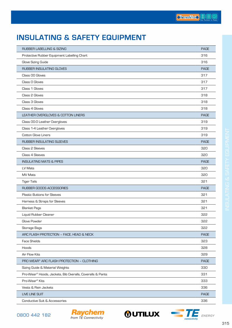
0800 442 182
315
INS
ULA
TIN
G &
SA
FETY
EQ
UIP
MEN
T
RUBBER LABELLING & SIZING PAGE
Protective Rubber Equipment Labelling Chart 316
Glove Sizing Guide 316
RUBBER INSULATING GLOVES PAGE
Class 00 Gloves 317
Class 0 Gloves 317
Class 1 Gloves 317
Class 2 Gloves 318
Class 3 Gloves 318
Class 4 Gloves 318
LEATHER OVERGLOVES & COTTON LINERS PAGE
Class 00-0 Leather Overgloves 319
Class 1-4 Leather Overgloves 319
Cotton Glove Liners 319
RUBBER INSULATING SLEEVES PAGE
Class 2 Sleeves 320
Class 4 Sleeves 320
INSULATING MATS & PIPES PAGE
LV Mats 320
MV Mats 320
Tiger Tails 321
RUBBER GOODS ACCESSORIES PAGE
Plastic Buttons for Sleeves 321
Harness & Straps for Sleeves 321
Blanket Pegs 321
Liquid Rubber Cleaner 322
Glove Powder 322
Storage Bags 322
ARC FLASH PROTECTION – FACE, HEAD & NECK PAGE
Face Shields 323
Hoods 328
Air Flow Kits 329
PRO WEAR® ARC FLASH PROTECTION – CLOTHING PAGE
Sizing Guide & Material Weights 330
Pro-Wear® Hoods, Jackets, Bib Overalls, Coveralls & Pants 331
Pro-Wear® Kits 333
Vests & Rain Jackets 336
LIVE LINE SUIT PAGE
Conductive Suit & Accessories 336
INSULATING & SAFETY EQUIPMENT
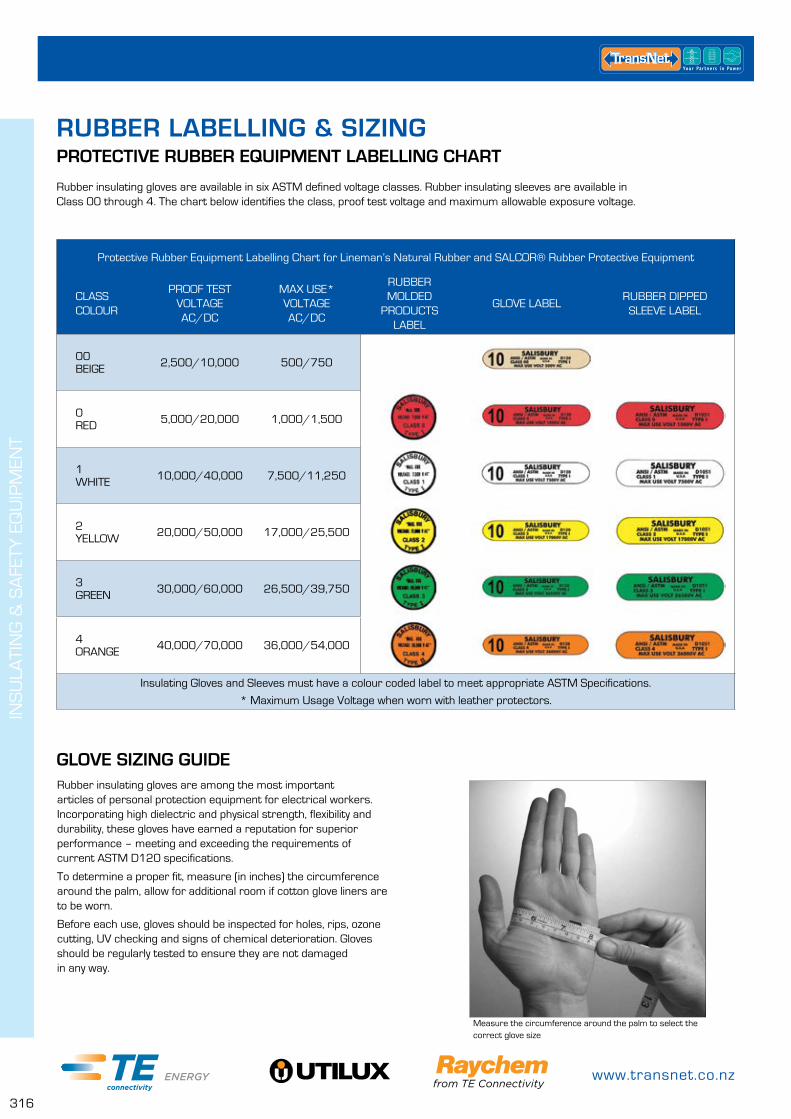
www.transnet.co.nz
316
INS
ULA
TIN
G &
SA
FETY
EQ
UIP
MEN
T
PROTECTIVE RUBBER EQUIPMENT LABELLING CHART
GLOVE SIZING GUIDE
Rubber insulating gloves are available in six ASTM defined voltage classes. Rubber insulating sleeves are available in Class 00 through 4. The chart below identifies the class, proof test voltage and maximum allowable exposure voltage.
Measure the circumference around the palm to select the correct glove size
Protective Rubber Equipment Labelling Chart for Lineman’s Natural Rubber and SALCOR® Rubber Protective Equipment
CLASS COLOUR
PROOF TESTVOLTAGEAC/DC
MAX USE*VOLTAGEAC/DC
RUBBERMOLDED
PRODUCTS LABEL
GLOVE LABELRUBBER DIPPED
SLEEVE LABEL
00 BEIGE 2,500/10,000 500/750
0RED 5,000/20,000 1,000/1,500
1WHITE 10,000/40,000 7,500/11,250
2YELLOW 20,000/50,000 17,000/25,500
3GREEN 30,000/60,000 26,500/39,750
4ORANGE 40,000/70,000 36,000/54,000
Insulating Gloves and Sleeves must have a colour coded label to meet appropriate ASTM Specifications.
* Maximum Usage Voltage when worn with leather protectors.
Rubber insulating gloves are among the most important articles of personal protection equipment for electrical workers. Incorporating high dielectric and physical strength, flexibility and durability, these gloves have earned a reputation for superior performance – meeting and exceeding the requirements of current ASTM D120 specifications.
To determine a proper fit, measure (in inches) the circumference around the palm, allow for additional room if cotton glove liners are to be worn.
Before each use, gloves should be inspected for holes, rips, ozone cutting, UV checking and signs of chemical deterioration. Gloves should be regularly tested to ensure they are not damaged in any way.
RUBBER LABELLING & SIZING

0800 442 182
317
INS
ULA
TIN
G &
SA
FETY
EQ
UIP
MEN
T
CAT NO. DESCRIPTION COLOUR
E0011R-8 1pr SALISBURY CL00 11 GLOVES SZ 8 RED
E0011R-8.5 1pr SALISBURY CL00 11 GLOVES SZ 8.5 RED
E0011R-9 1pr SALISBURY CL00 11 GLOVE SZ 9 RED
E0011R-9.5 1pr SALISBURY CL00 11 GLOVE SZ 9.5 RED
E0011R-10 1pr SALISBURY CL00 11 GLOVE SZ 10 RED
E0011R-10.5 1pr SALISBURY CL00 11 GLOVE SZ 10.5 RED
E0011R-11 1pr SALISBURY CL00 11 GLOVE SZ 11 RED
E0011R-11.5 1pr SALISBURY CL00 11 GLOVE SZ 11.5 RED
E0011R-12 1pr SALISBURY CL00 11 GLOVES SZ 12 RED
CLASS 00 RUBBER INSULATING GLOVES – MAX USE VOLTAGE 500V AC• Available in solid colour (Red, and Blue) with other solid colours available upon request
• 11 inch length*
*Other lengths available on request
CAT NO. DESCRIPTION COLOUR
E011Y-8 1pr SALISBURY CL0 11 GLOVES SZ 8 YELLOW
E011Y-8.5 1pr SALISBURY CL0 11 GLOVES SZ 8.5 YELLOW
E011Y-9 1pr SALISBURY CL0 11 GLOVES SZ 9 YELLOW
E011Y-9.5 1pr SALISBURY CL0 11 GLOVES SZ 9.5 YELLOW
E011Y-10 1pr SALISBURY CL0 11 GLOVES SZ 10 YELLOW
E011Y-10.5 1pr SALISBURY CL0 11 GLOVES SZ 10.5 YELLOW
E011Y-11 1pr SALISBURY CL0 11 GLOVES SZ 11 YELLOW
E011Y-12 1pr SALISBURY CL0 11 GLOVES SZ 12 YELLOW
CLASS 0 RUBBER INSULATING GLOVES – MAX USE VOLTAGE 1000V AC• Available in solid colour (Black or Yellow) with other solid colours available upon request
• 11 inch length*
*Other lengths available on request
CAT NO. DESCRIPTION COLOUR
E114YB-8 1pr SALISBURY CL1 14 GLOVES SZ 8 YELLOW/BLACK
E114YB-8.5 1pr SALISBURY CL1 14 GLOVES SZ 8.5 YELLOW/BLACK
E114YB-9 1pr SALISBURY CL1 14 GLOVES SZ 9 YELLOW/BLACK
E114YB-9.5 1pr SALISBURY CL1 14 GLOVES SZ 9.5 YELLOW/BLACK
E114YB-10 1pr SALISBURY CL1 14 GLOVE SZ 10 YELLOW/BLACK
E114YB-10.5 1pr SALISBURY CL1 14 GLOVES SZ 10.5 YELLOW/BLACK
E114YB-11 1pr SALISBURY CL1 14 GLOVE SZ 11 YELLOW/BLACK
E114YB-12 1pr SALISBURY CL1 14 GLOVE SZ 12 YELLOW/BLACK
CLASS 1 RUBBER INSULATING GLOVES – MAX USE VOLTAGE 7,500V AC• Available in dual colour
• 14 inch length*
*Other lengths available on request
RUBBER INSULATING GLOVES
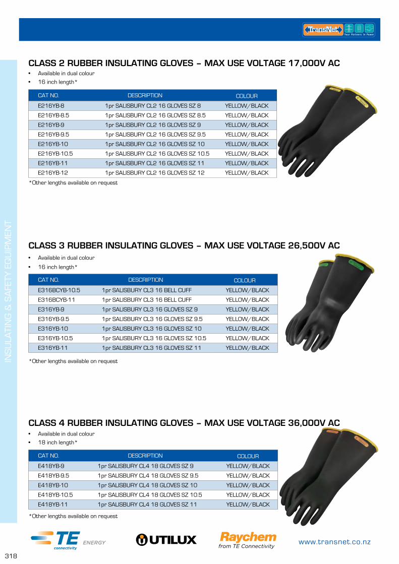
www.transnet.co.nz
318
INS
ULA
TIN
G &
SA
FETY
EQ
UIP
MEN
T
CAT NO. DESCRIPTION COLOUR
E216YB-8 1pr SALISBURY CL2 16 GLOVES SZ 8 YELLOW/BLACK
E216YB-8.5 1pr SALISBURY CL2 16 GLOVES SZ 8.5 YELLOW/BLACK
E216YB-9 1pr SALISBURY CL2 16 GLOVES SZ 9 YELLOW/BLACK
E216YB-9.5 1pr SALISBURY CL2 16 GLOVES SZ 9.5 YELLOW/BLACK
E216YB-10 1pr SALISBURY CL2 16 GLOVES SZ 10 YELLOW/BLACK
E216YB-10.5 1pr SALISBURY CL2 16 GLOVES SZ 10.5 YELLOW/BLACK
E216YB-11 1pr SALISBURY CL2 16 GLOVES SZ 11 YELLOW/BLACK
E216YB-12 1pr SALISBURY CL2 16 GLOVES SZ 12 YELLOW/BLACK
CLASS 2 RUBBER INSULATING GLOVES – MAX USE VOLTAGE 17,000V AC• Available in dual colour
• 16 inch length*
*Other lengths available on request
CAT NO. DESCRIPTION COLOUR
E316BCYB-10.5 1pr SALISBURY CL3 16 BELL CUFF YELLOW/BLACK
E316BCYB-11 1pr SALISBURY CL3 16 BELL CUFF YELLOW/BLACK
E316YB-9 1pr SALISBURY CL3 16 GLOVES SZ 9 YELLOW/BLACK
E316YB-9.5 1pr SALISBURY CL3 16 GLOVES SZ 9.5 YELLOW/BLACK
E316YB-10 1pr SALISBURY CL3 16 GLOVES SZ 10 YELLOW/BLACK
E316YB-10.5 1pr SALISBURY CL3 16 GLOVES SZ 10.5 YELLOW/BLACK
E316YB-11 1pr SALISBURY CL3 16 GLOVES SZ 11 YELLOW/BLACK
CLASS 3 RUBBER INSULATING GLOVES – MAX USE VOLTAGE 26,500V AC• Available in dual colour
• 16 inch length*
*Other lengths available on request
CAT NO. DESCRIPTION COLOUR
E418YB-9 1pr SALISBURY CL4 18 GLOVES SZ 9 YELLOW/BLACK
E418YB-9.5 1pr SALISBURY CL4 18 GLOVES SZ 9.5 YELLOW/BLACK
E418YB-10 1pr SALISBURY CL4 18 GLOVES SZ 10 YELLOW/BLACK
E418YB-10.5 1pr SALISBURY CL4 18 GLOVES SZ 10.5 YELLOW/BLACK
E418YB-11 1pr SALISBURY CL4 18 GLOVES SZ 11 YELLOW/BLACK
CLASS 4 RUBBER INSULATING GLOVES – MAX USE VOLTAGE 36,000V AC• Available in dual colour
• 18 inch length*
*Other lengths available on request
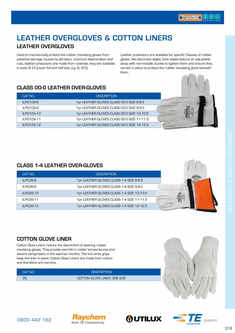
0800 442 182
319
INS
ULA
TIN
G &
SA
FETY
EQ
UIP
MEN
T
Used to mechanically protect the rubber insulating gloves from potential damage caused by abrasion, chemical deterioration and cuts, leather protectors are made from cowhide, they are available in sizes 8-12 (cover full and half size, e.g. 8/8.5).
CAT NO. DESCRIPTION
ILPG10A-8 1pr LEATHER GLOVES CLASS 00-0 SIZE 8-8.5
ILPG10A-9 1pr LEATHER GLOVES CLASS 00-0 SIZE 9-9.5
ILPG10A-10 1pr LEATHER GLOVES CLASS 00-0 SIZE 10-10.5
ILPG10A-11 1pr LEATHER GLOVES CLASS 00-0 SIZE 11-11.5
ILPG10A-12 1pr LEATHER GLOVES CLASS 00-0 SIZE 12-12.5
CLASS 00-0 LEATHER OVER-GLOVES
CAT NO. DESCRIPTION
ILPG3S-8 1pr LEATHER GLOVES CLASS 1-4 SIZE 8-8.5
ILPG3S-9 1pr LEATHER GLOVES CLASS 1-4 SIZE 9-9.5
ILPG3S-10 1pr LEATHER GLOVES CLASS 1-4 SIZE 10-10.5
ILPG3S-11 1pr LEATHER GLOVES CLASS 1-4 SIZE 11-11.5
ILPG3S-12 1pr LEATHER GLOVES CLASS 1-4 SIZE 12-12.5
CLASS 1-4 LEATHER OVER-GLOVES
CAT NO. DESCRIPTION
35 COTTON GLOVE LINER, ONE SIZE
COTTON GLOVE LINERCotton Glove Liners reduce the discomfort of wearing rubber insulating gloves. They provide warmth in colder temperatures and absorb perspiration in the warmer months. The knit wrist grips keep the liner in place. Cotton Glove Liners are made from cotton and therefore are non-drip.
Leather protectors are available for specific Classes of rubber gloves. We stock two styles, both styles feature an adjustable strap with non-metallic buckle to tighten them and ensure they remain in place to protect the rubber insulating glove beneath them.
LEATHER OVERGLOVES LEATHER OVERGLOVES & COTTON LINERS
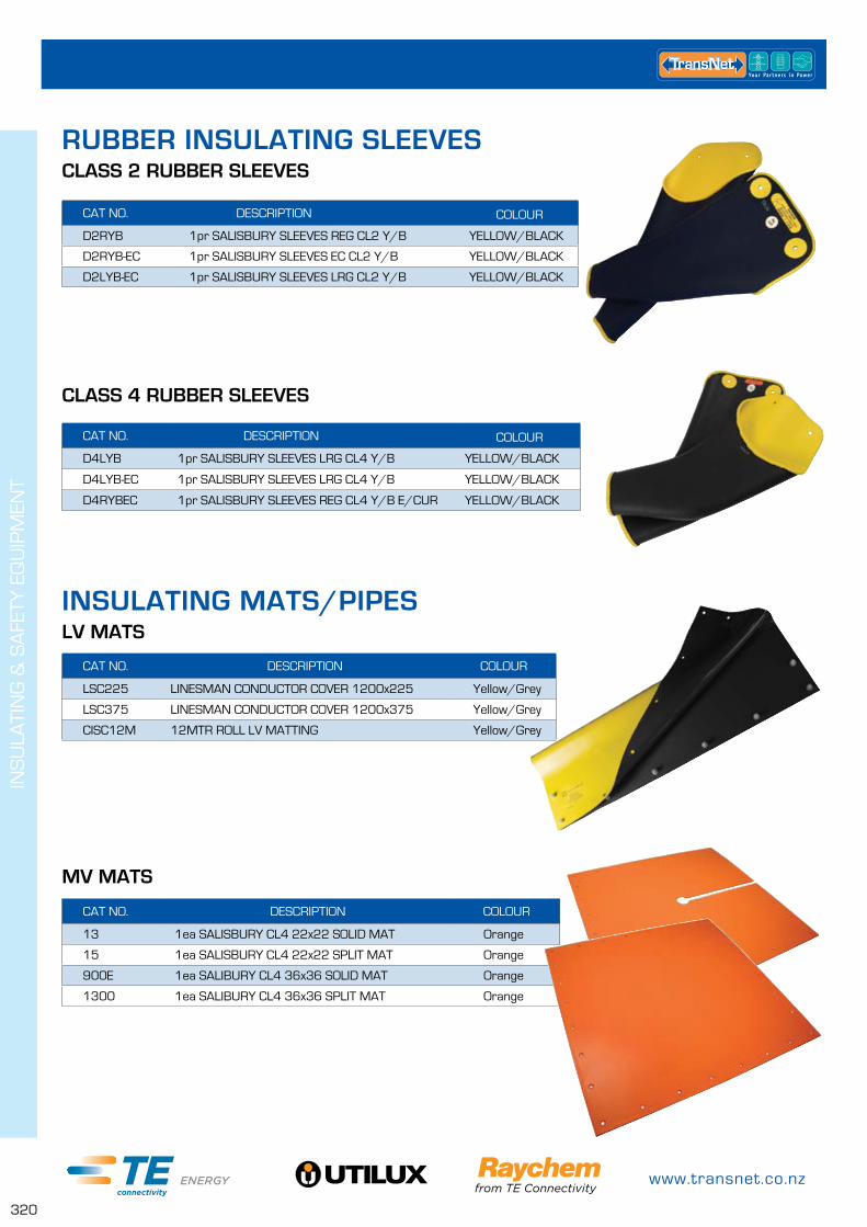
www.transnet.co.nz
320
INS
ULA
TIN
G &
SA
FETY
EQ
UIP
MEN
T
CAT NO. DESCRIPTION COLOUR
LSC225 LINESMAN CONDUCTOR COVER 1200x225 Yellow/Grey
LSC375 LINESMAN CONDUCTOR COVER 1200x375 Yellow/Grey
CISC12M 12MTR ROLL LV MATTING Yellow/Grey
LV MATS
CAT NO. DESCRIPTION COLOUR
13 1ea SALISBURY CL4 22x22 SOLID MAT Orange
15 1ea SALISBURY CL4 22x22 SPLIT MAT Orange
900E 1ea SALIBURY CL4 36x36 SOLID MAT Orange
1300 1ea SALIBURY CL4 36x36 SPLIT MAT Orange
MV MATS
CAT NO. DESCRIPTION COLOUR
D2RYB 1pr SALISBURY SLEEVES REG CL2 Y/B YELLOW/BLACK
D2RYB-EC 1pr SALISBURY SLEEVES EC CL2 Y/B YELLOW/BLACK
D2LYB-EC 1pr SALISBURY SLEEVES LRG CL2 Y/B YELLOW/BLACK
CAT NO. DESCRIPTION COLOUR
D4LYB 1pr SALISBURY SLEEVES LRG CL4 Y/B YELLOW/BLACK
D4LYB-EC 1pr SALISBURY SLEEVES LRG CL4 Y/B YELLOW/BLACK
D4RYBEC 1pr SALISBURY SLEEVES REG CL4 Y/B E/CUR YELLOW/BLACK
CLASS 4 RUBBER SLEEVES
CLASS 2 RUBBER SLEEVESRUBBER INSULATING SLEEVES
INSULATING MATS/PIPES
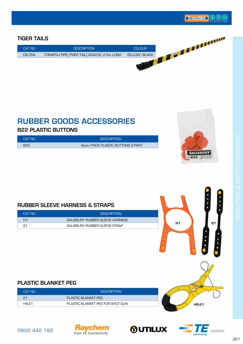
0800 442 182
321
INS
ULA
TIN
G &
SA
FETY
EQ
UIP
MEN
T
CAT NO. DESCRIPTION
B22 4pce/PACK PLASTIC BUTTONS 2-PART
CAT NO. DESCRIPTION
H1 SALISBURY RUBBER SLEEVE HARNESS
S1 SALISBURY RUBBER SLEEVE STRAP
CAT NO. DESCRIPTION
21 PLASTIC BLANKET PEG
HS-21 PLASTIC BLANKET PEG FOR SHOT GUN
B22 PLASTIC BUTTONS
RUBBER SLEEVE HARNESS & STRAPS
PLASTIC BLANKET PEG
RUBBER GOODS ACCESSORIES
CAT NO. DESCRIPTION COLOUR
DB.35A TORAPOLI PIPE (TIGER TAIL) AS4202, 2.5m LONG YELLOW/BLACK
TIGER TAILS
H1
HS-21
S1
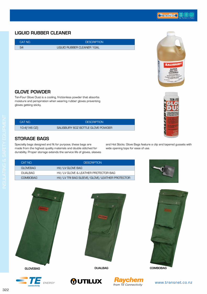
www.transnet.co.nz
322
INS
ULA
TIN
G &
SA
FETY
EQ
UIP
MEN
T
CAT NO. DESCRIPTION
10-4(1X6 OZ) SALISBURY 6OZ BOTTLE GLOVE POWDER
CAT NO. DESCRIPTION
GLOVEBAG HV/LV GLOVE BAG
DUALBAG HV/LV GLOVE & LEATHER PROTECTOR BAG
COMBOBAG HV/LV TRI BAG SLEEVE/GLOVE/LEATHER PROTECTOR
GLOVE POWDER
STORAGE BAGS
Ten-Four Glove Dust is a cooling, frictionless powder that absorbs moisture and perspiration when wearing rubber gloves preventing gloves getting sticky.
Specialty bags designed and fit for purpose, these bags are made from the highest quality materials and double stitched for durability. Proper storage extends the service life of gloves, sleeves
COMBOBAGGLOVEBAG DUALBAG
and Hot Sticks. Glove Bags feature a clip and tapered gussets with wide opening tops for ease of use.
CAT NO. DESCRIPTION
S4 LIQUID RUBBER CLEANER 1GAL
LIQUID RUBBER CLEANER

0800 442 182
323
INS
ULA
TIN
G &
SA
FETY
EQ
UIP
MEN
T
ARC FLASH PROTECTION – FACE, HEAD & NECKAS2000 & AS1200 SERIES
AS1200 UNIVERSAL FIT PROTECTIVE FACE SHIELD – HRC2, 12 CAL/CM²
AS2000HAT Series• 7.5” x 20” viewing area• Extra light tint• .06” thick• Absorbs >99.9% of harmful UV radiation• Resitant to fogging• Meets current ANSI Z87.1 and is CSA standard compliant • Tested to ASTM F2178 specifications• 20 cal/cm² ATPV rating• Ventilation ribs for natural convection air flow for less fogging & lower CO
2 levels
AS1200HAT Series• 7.5” x 20” viewing area• Extra light tint• .06” thick• Absorbs >99.9% of harmful UV radiation• Resitant to fogging• Meets current ANSI Z87.1 and is CSA standard compliant • Tested to ASTM F2178 specifications• 12 cal/cm² ATPV rating• Ventilation ribs for natural convection air flow for less fogging & lower CO
2 levels
Universal Fit AS1200FB & AS1200UWeight balancing arc flash protection faceshields that fit all popular full brim (AS1200FB) and front brim (AS1200U) hard hats. An elastomeric band secures the bracket to the brim o f the hard hat. All parts are dielectric and specifically designed for arc flash protection.
• ATPV rating is 12 cal/cm²• Upper bracket ventilation feature for natural air flow to reduce fogging & lower CO
2 levels
• Transparent Chin Guard is an optional accessory & increases peripheral view dramatically• 7.5” x 20” viewing area• Extra light tint• .06” thick• Absorbs >99.9% of harmful UV radiation• Resitant to fogging• Meets current ANSI Z87.1 and is CSA standard compliant &
tested to ASTM F2178 specifications• Unique weight balancing design• Optional task light feature• Replaceable window, no tools required• Adjustable pivot tension• One hand operation
CAT NO. DESCRIPTION
AS2000HST 20 cal/cm², ARC FLASH PROTECTION FACESHIELD UNIT WITH SA79R03 HARD HAT
AS2000 20 cal/cm², ARC FLASH PROTECTION FACESHIELD UNIT
AS2000FS REPLACEMENT FACESHIELD/WINDOW
AS1200HAT WEIGHT BALANCING ARC FLASH PROTECTION FACESHIELD UNIT WITH HARD HAT
AS1200HATCLR AS1200HAT WITH TRANSPARENT CHIN GUARD
AS1200 WEIGHT BALANCING ARC FLASH PROTECTION FACESHIELD UNIT
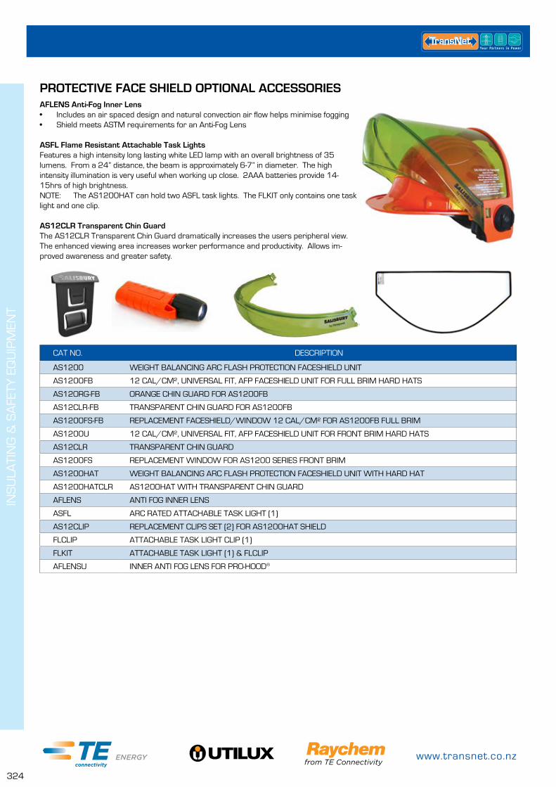
www.transnet.co.nz
324
INS
ULA
TIN
G &
SA
FETY
EQ
UIP
MEN
T
PROTECTIVE FACE SHIELD OPTIONAL ACCESSORIESAFLENS Anti-Fog Inner Lens• Includes an air spaced design and natural convection air flow helps minimise fogging • Shield meets ASTM requirements for an Anti-Fog Lens
ASFL Flame Resistant Attachable Task LightsFeatures a high intensity long lasting white LED lamp with an overall brightness of 35 lumens. From a 24” distance, the beam is approximately 6-7” in diameter. The high intensity illumination is very useful when working up close. 2AAA batteries provide 14-15hrs of high brightness.NOTE: The AS1200HAT can hold two ASFL task lights. The FLKIT only contains one task light and one clip.
AS12CLR Transparent Chin GuardThe AS12CLR Transparent Chin Guard dramatically increases the users peripheral view. The enhanced viewing area increases worker performance and productivity. Allows im-proved awareness and greater safety.
CAT NO. DESCRIPTION
AS1200 WEIGHT BALANCING ARC FLASH PROTECTION FACESHIELD UNIT
AS1200FB 12 CAL/CM², UNIVERSAL FIT, AFP FACESHIELD UNIT FOR FULL BRIM HARD HATS
AS12ORG-FB ORANGE CHIN GUARD FOR AS1200FB
AS12CLR-FB TRANSPARENT CHIN GUARD FOR AS1200FB
AS1200FS-FB REPLACEMENT FACESHIELD/WINDOW 12 CAL/CM² FOR AS1200FB FULL BRIM
AS1200U 12 CAL/CM², UNIVERSAL FIT, AFP FACESHIELD UNIT FOR FRONT BRIM HARD HATS
AS12CLR TRANSPARENT CHIN GUARD
AS1200FS REPLACEMENT WINDOW FOR AS1200 SERIES FRONT BRIM
AS1200HAT WEIGHT BALANCING ARC FLASH PROTECTION FACESHIELD UNIT WITH HARD HAT
AS1200HATCLR AS1200HAT WITH TRANSPARENT CHIN GUARD
AFLENS ANTI FOG INNER LENS
ASFL ARC RATED ATTACHABLE TASK LIGHT (1)
AS12CLIP REPLACEMENT CLIPS SET (2) FOR AS1200HAT SHIELD
FLCLIP ATTACHABLE TASK LIGHT CLIP (1)
FLKIT ATTACHABLE TASK LIGHT (1) & FLCLIP
AFLENSU INNER ANTI FOG LENS FOR PRO-HOOD®
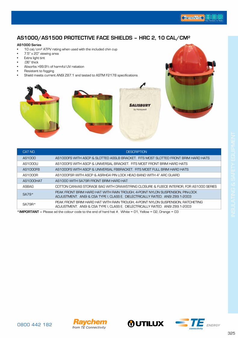
0800 442 182
325
INS
ULA
TIN
G &
SA
FETY
EQ
UIP
MEN
T
AS1000/AS1500 PROTECTIVE FACE SHIELDS – HRC 2, 10 CAL/CM²AS1000 Series• 10 cal/cm² ATPV rating when used with the included chin cup• 7.5” x 20” viewing area• Extra light tint• .06” thick• Absorbs >99.9% of harmful UV ratiation• Resistant to fogging• Shield meets current ANSI Z87.1 and tested to ASTM F2178 specifications
CAT NO. DESCRIPTION
AS1000 AS1000FS WITH ASCP & SLOTTED ASSLB BRACKET. FITS MOST SLOTTED FRONT BRIM HARD HATS
AS1000U AS1000FS WITH ASCP & UNIVERSAL BRACKET. FITS MOST FRONT BRIM HARD HATS
AS1000FB AS1000FS WITH ASCP & UNIVERSAL FBBRACKET. FITS MOST FULL BRIM HARD HATS
AS1000R AS1000FSR WITH ASCP & ASRHG4 PIN LOCK HEAD BAND WITH 4” ARC GUARD
AS1000HAT AS1000 WITH SA79R FRONT BRIM HARD HAT
ASBAG COTTON CANVAS STORAGE BAG WITH DRAWSTRING CLOSURE & FLEECE INTERIOR, FOR AS1000 SERIES
SA79*PEAK FRONT BRIM HARD HAT WITH RAIN TROUGH, 4-POINT NYLON SUSPENSION, PIN-LOCK ADJUSTMENT. ANSI & CSA TYPE I, CLASS E. DIELECTRICALLY RATED. ANSI Z89.1-2003
SA79R*PEAK FRONT BRIM HARD HAT WITH RAIN TROUGH, 4-POINT NYLON SUSPENSION, RATCHETING ADJUSTMENT. ANSI & CSA TYPE I, CLASS E. DIELECTRICALLY RATED. ANSI Z89.1-2003
*IMPORTANT – Please ad the colour code to the end of hard hat #. White = 01, Yellow = 02, Orange = 03
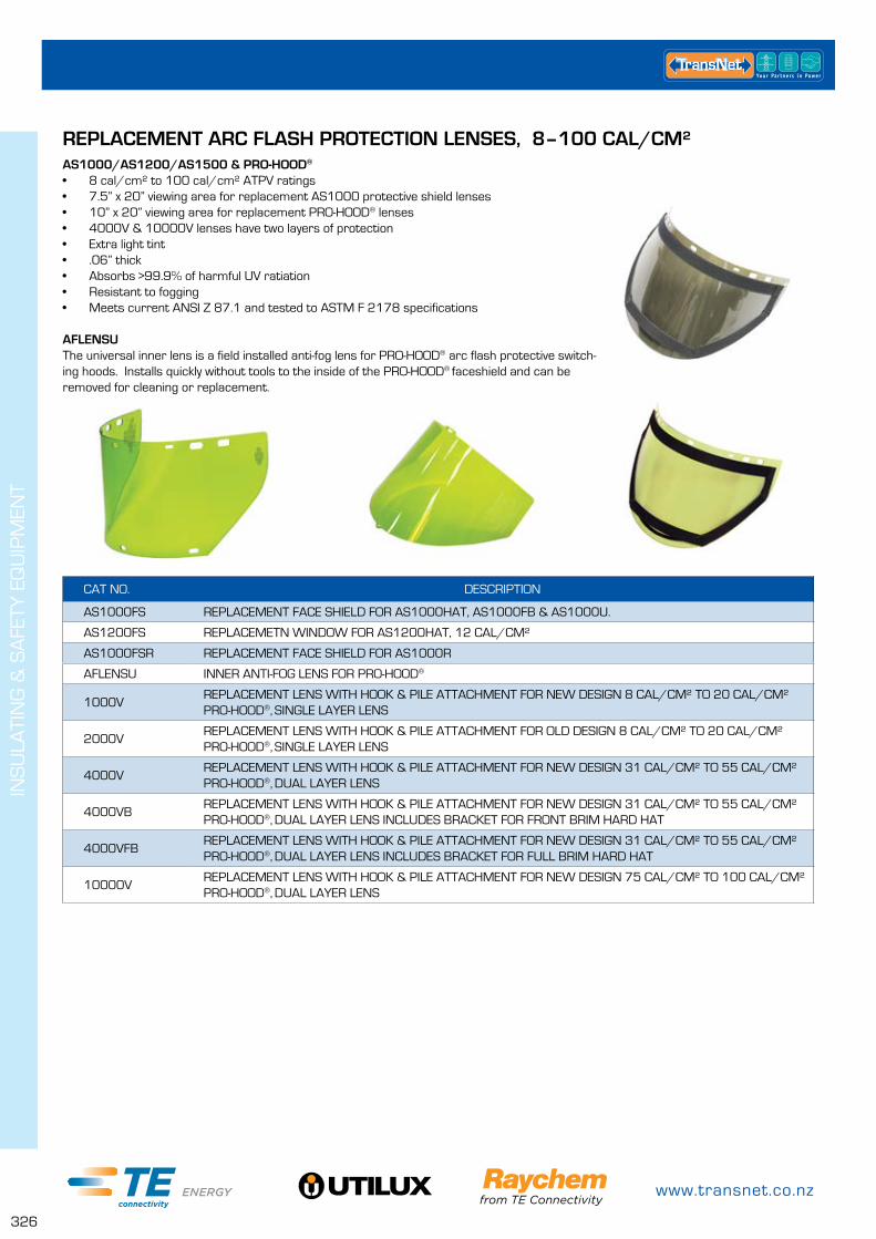
www.transnet.co.nz
326
INS
ULA
TIN
G &
SA
FETY
EQ
UIP
MEN
T
REPLACEMENT ARC FLASH PROTECTION LENSES, 8–100 CAL/CM²AS1000/AS1200/AS1500 & PRO-HOOD®
• 8 cal/cm² to 100 cal/cm² ATPV ratings• 7.5” x 20” viewing area for replacement AS1000 protective shield lenses• 10” x 20” viewing area for replacement PRO-HOOD® lenses• 4000V & 10000V lenses have two layers of protection • Extra light tint• .06” thick• Absorbs >99.9% of harmful UV ratiation• Resistant to fogging• Meets current ANSI Z 87.1 and tested to ASTM F 2178 specifications
AFLENSUThe universal inner lens is a field installed anti-fog lens for PRO-HOOD® arc flash protective switch-ing hoods. Installs quickly without tools to the inside of the PRO-HOOD® faceshield and can be removed for cleaning or replacement.
CAT NO. DESCRIPTION
AS1000FS REPLACEMENT FACE SHIELD FOR AS1000HAT, AS1000FB & AS1000U.
AS1200FS REPLACEMETN WINDOW FOR AS1200HAT, 12 CAL/CM²
AS1000FSR REPLACEMENT FACE SHIELD FOR AS1000R
AFLENSU INNER ANTI-FOG LENS FOR PRO-HOOD®
1000VREPLACEMENT LENS WITH HOOK & PILE ATTACHMENT FOR NEW DESIGN 8 CAL/CM² TO 20 CAL/CM² PRO-HOOD®, SINGLE LAYER LENS
2000VREPLACEMENT LENS WITH HOOK & PILE ATTACHMENT FOR OLD DESIGN 8 CAL/CM² TO 20 CAL/CM² PRO-HOOD®, SINGLE LAYER LENS
4000VREPLACEMENT LENS WITH HOOK & PILE ATTACHMENT FOR NEW DESIGN 31 CAL/CM² TO 55 CAL/CM² PRO-HOOD®, DUAL LAYER LENS
4000VBREPLACEMENT LENS WITH HOOK & PILE ATTACHMENT FOR NEW DESIGN 31 CAL/CM² TO 55 CAL/CM² PRO-HOOD®, DUAL LAYER LENS INCLUDES BRACKET FOR FRONT BRIM HARD HAT
4000VFBREPLACEMENT LENS WITH HOOK & PILE ATTACHMENT FOR NEW DESIGN 31 CAL/CM² TO 55 CAL/CM² PRO-HOOD®, DUAL LAYER LENS INCLUDES BRACKET FOR FULL BRIM HARD HAT
10000VREPLACEMENT LENS WITH HOOK & PILE ATTACHMENT FOR NEW DESIGN 75 CAL/CM² TO 100 CAL/CM² PRO-HOOD®, DUAL LAYER LENS

0800 442 182
327
INS
ULA
TIN
G &
SA
FETY
EQ
UIP
MEN
T
REPLACEMENT BRACKETS, PROTECTIVE NETS & SAFETY GLASSESFire Resistant Hairnet & BeardnetGive added protection in any industry that requires the worker to wear a hairnet or beardnet. With ATPV rating of 2.4 cal/cm², they are available in Grey only. Made from washable 1.7 oz/yd² (58g/m²) woven Nomex® fabric. Meets current ASTM F1506 standards.
Safety GlassesAnti-fogging, anti-scratch and anti-static, with 99.9% UV protection, these glasses meet cur-rent ANSI Z87.1, 2003 and CSA Z94.3* standards.
* The CSA Z94.3 standard applies to eye and face protectors used in all occupational and educational operations or processes involving hazards to the eyes or face.
CAT NO. DESCRIPTION
ASCP REPLACEMENT CHIN CUP FOR AS1000 SERIES SHIELDS
BRACKETUNIVERSAL DIELECTRIC HARD HAT BRACKET, USED WITH FRONT BRIM HARD HATS
FBBRACKETUNIVERSAL DIELECTRIC HARD HAT BRACKET, USED WITH FULL BRIM HARD HATS
ASSLBDIELECTRIC BRACKET, FITS SLOTTED FRONT BRIM HARD HATS. USED WITH ALL AS1000 SERIES LENSES
ASRHG4RATCHETED HEAD GEAR WITH 4” ARC GUARD. USED WITH AS1000FSR LENS
HN-1ARC RATED PROTECTIVE HAIRNET, 2.4 CAL/CM², 1.7 OZ/YD² (58 G/M²) WOVEN NOMEX®
BN-1ARC RATED PROTECTIVE BEARDNET, 2.4 CAL/CM², 1.7 OZ/YD² (58 G/M²) WOVEN NOMEX®
T56505GRY CLEAR LENS, GREY FRAME
TS56505GRYA AMBER LENS, GREY FRAME
TS56505GRYS SMOKE LENS, GREY FRAME
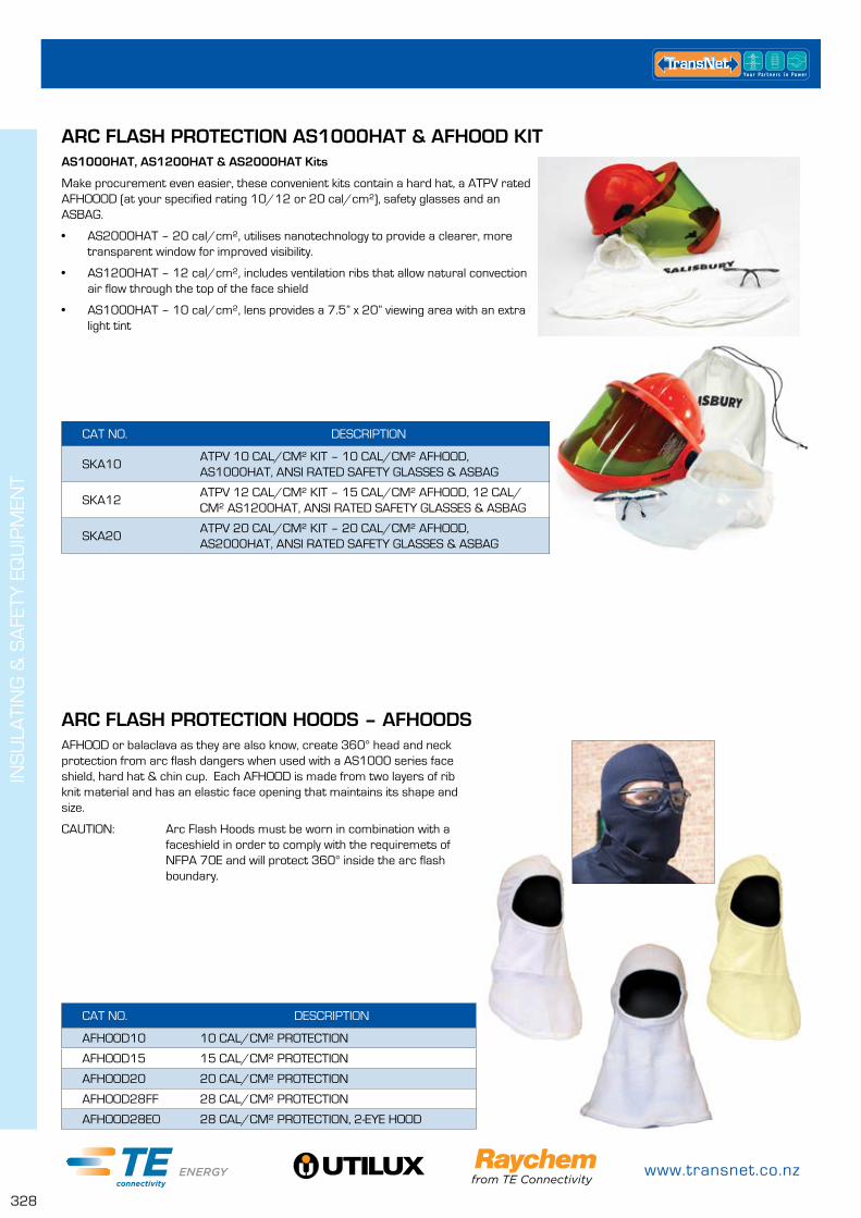
www.transnet.co.nz
328
INS
ULA
TIN
G &
SA
FETY
EQ
UIP
MEN
T
ARC FLASH PROTECTION AS1000HAT & AFHOOD KITAS1000HAT, AS1200HAT & AS2000HAT Kits
Make procurement even easier, these convenient kits contain a hard hat, a ATPV rated AFHOOOD (at your specified rating 10/12 or 20 cal/cm²), safety glasses and an ASBAG.
• AS2000HAT – 20 cal/cm², utilises nanotechnology to provide a clearer, more transparent window for improved visibility.
• AS1200HAT – 12 cal/cm², includes ventilation ribs that allow natural convection air flow through the top of the face shield
• AS1000HAT – 10 cal/cm², lens provides a 7.5” x 20” viewing area with an extra light tint
CAT NO. DESCRIPTION
SKA10ATPV 10 CAL/CM² KIT – 10 CAL/CM² AFHOOD, AS1000HAT, ANSI RATED SAFETY GLASSES & ASBAG
SKA12ATPV 12 CAL/CM² KIT – 15 CAL/CM² AFHOOD, 12 CAL/CM² AS1200HAT, ANSI RATED SAFETY GLASSES & ASBAG
SKA20ATPV 20 CAL/CM² KIT – 20 CAL/CM² AFHOOD, AS2000HAT, ANSI RATED SAFETY GLASSES & ASBAG
ARC FLASH PROTECTION HOODS – AFHOODSAFHOOD or balaclava as they are also know, create 360° head and neck protection from arc flash dangers when used with a AS1000 series face shield, hard hat & chin cup. Each AFHOOD is made from two layers of rib knit material and has an elastic face opening that maintains its shape and size.
CAUTION: Arc Flash Hoods must be worn in combination with a faceshield in order to comply with the requiremets of NFPA 70E and will protect 360° inside the arc flash boundary.
CAT NO. DESCRIPTION
AFHOOD10 10 CAL/CM² PROTECTION
AFHOOD15 15 CAL/CM² PROTECTION
AFHOOD20 20 CAL/CM² PROTECTION
AFHOOD28FF 28 CAL/CM² PROTECTION
AFHOOD28EO 28 CAL/CM² PROTECTION, 2-EYE HOOD

0800 442 182
329
INS
ULA
TIN
G &
SA
FETY
EQ
UIP
MEN
T
COMPACT PRO-AIR™ ACAIR2000®
Designed to blow forced ambient air through a single intake hose, providing fresh oxygen to the worker and reducing the hazardous effects of shield fogging. The unit is microprocessor controlled and operates automatically by blowing air continuously for over three hours onone charge. Ont eh back of the unit is a button that pauses the continuous flow, if needed. Use this unit with Salisbury's PRO-HOOD® and PRO-WEAR® arc flash protection clothing.
The PRO-AIR ACAIR2000 is a compact powered air system that easily mounts to most standard hardhats and functions in one light weight (less than 10 oz.), easy to use unit. The unit cools the worker and reduces fatigue while wearing a Salisbury Arc Flash PRO-HOOD®.
It includes a light weight blower assembly, universal band, bendable intake hose, Ni-MH recharge-able batteries and an AC wall charger.
CAT NO. DESCRIPTION
ACAIR2000 PRO-AIR LIGHT WEIGHT AIR SYSTEM FOR PRO-HOODS®
AIRFLOW HOOD SYSTEM & COMPACT PRO-AIR™ ACAIR102The PRO-AIR™ Air Flow Hood System is integrated with Salisbury's PRO-HOOD® Arc Flash Protection Hood. Now, all Salisbury PRO-HOOD® Arc Flash Protection Hood. Now all hoods are available with an optional integrated cooling system. This newest addition to the PRO-AIR™ line of products provides additional air flow and cools the worker. This unit is excellent in warm conditions or confined spaces. the easy to wear system is light weight, compact and easy to use. The system is designed to provide the worker with approximately 80cfm of air flow throughout the breathing zone. the unit is powered by 8 AA batteries and is designed to maintain a useful continuous life of up to 35hrs at 80cfm. The unit is non-filtered and is not consid-ered a respirator.
The PRO-AIR kit consists of a blower unit, belt and comfort pad, rechargeable bat-tery pack, breathing hose and battery charger. Blower unit and hose are cov ered with a fire resistant material to meet NFPA 70E requirements. The PRO-AIR™ kit is shipped in a durable carrying case.
This belt mounted system provides a continuous flow of filtered air to reduce worker fatigue and provide additional comfort when working in hot and humid conditions. The PRO-AIR™ integrates with the full ATPV range of Salisbury's PRO-HOOD® line and easily attaches inside the hood using the exclusive Salisbury hook and pile looped fastener system.
CAT NO. DESCRIPTION
FH8BL-C 8 CAL/CM² ARC FLASH HOOD WITH AIR SYSTEM
FH11BL-C 12 CAL/CM² ARC FLASH HOOD WITH AIR SYSTEM
FH20BL-C 20 CAL/CM² ARC FLASH HOOD WITH AIR SYSTEM
FH31RB-C 31 CAL/CM² ARC FLASH HOOD WITH AIR SYSTEM
FH40GY-C 40 CAL/CM² ARC FLASH HOOD WITH AIR SYSTEM
FH40PLT-C NEW 40 CAL/CM² ARC FLASH HOOD WITH AIR SYSTEM
FH55GY-C 55 CAL/CM² ARC FLASH HOOD WITH AIR SYSTEM
FH75GY-C 75 CAL/CM² ARC FLASH HOOD WITH AIR SYSTEM
FH100TW-C 100 CAL/CM² ARC FLASH HOOD WITH AIR SYSTEM
ACAIR102 PRO-AIR COMPACT PROWERED AIR SYSTEM, COMPLETE KIT
AC103 PRO-AIR BATTERY
A168091 REPLACEMENT AIR FILTER CARTRIDGES
AC124 O-RINGS FOR AIR FILTERS
AC129 Y SHAPED BREATHING HOSE
AC129FR FIRE RETARDENT TUBE COVERS FOR AC129 (3)
AC131 SINGLE UNIT BATTERY CHARGER
AC135 COMPACT POWERED AIR SYSTEM CARRYING CASE
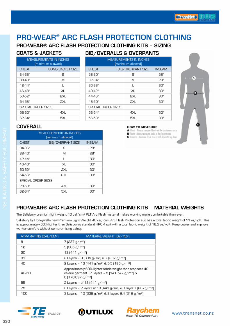
www.transnet.co.nz
330
INS
ULA
TIN
G &
SA
FETY
EQ
UIP
MEN
T
MEASUREMENTS IN INCHES (minimum allowed)
CHEST COAT/JACKET SIZE
34-36" S
38-40" M
42-44" L
46-48" XL
50-52" 2XL
54-56" 2XL
SPECIAL ORDER SIZES
58-60" 4XL
62-64" 5XL
MEASUREMENTS IN INCHES (minimum allowed)
CHEST BIB/OVERPANT SIZE INSEAM
28-30" S 28"
32-34" M 29"
36-38" L 30"
40-42" XL 30"
44-46" 2XL 30"
48-50" 2XL 30"
SPECIAL ORDER SIZES
52-54" 4XL 30"
56-58" 5XL 30"
MEASUREMENTS IN INCHES (minimum allowed)
CHEST BIB/OVERPANT SIZE INSEAM
34-36" S 28"
38-40" M 29"
42-44" L 30"
46-48" XL 30"
50-52" 2XL 30"
54-56" 2XL 30"
SPECIAL ORDER SIZES
28-60" 4XL 30"
62-64" 5XL 30"
PRO-WEAR® ARC FLASH PROTECTION CLOTHING
COATS & JACKETSPRO-WEAR® ARC FLASH PROTECTION CLOTHING KITS – SIZING
BIB/OVERALLS & OVERPANTS
COVERALL
ATPV RATING (CAL/CM²) MATERIAL WEIGHT (OZ/YD²)
8 7 (237 g/m²)
12 9 (305 g/m²)
20 13 (441 g/m²)
31 2 Layers – 9 (305 g/m²) & 7 (237 g/m²)
40 2 Layers – 13 (441 g/m²) & 5.5 (186 g/m²)
40-PLTApproximately 60% lighter fabric weight than standard 40 calorie garment. 2 Layers – 5 (141.747 g/m²) & 6 (170.097 g/m²)
55 2 Layers – of 13 (441 g/m²)
75 3 Layers – 2 layers of 13 (441 g/m²) & 1 layer 7 (237g/m²)
100 3 Layers – 10 (339 g/m²) & 2 layers 9.4 (319 g/m²)
The Salisbury premium light weight 40 cal/cm² PLT Arc Flash material makes working more comfortable than ever.
Salisbury by Honeywell's new Premium Light Weight 40 cal/cm² Arc Flash Protection suit has a total fabric weight of 11 oz/yd². This is approximately 60% lighter than Salisbury's standard HRC 4 suit with a total fabric weight of 18.5 oz/yd². Keep cooler and improve worker comfort without compromising safety.
PRO-WEAR® ARC FLASH PROTECTION CLOTHING KITS – MATERIAL WEIGHTS
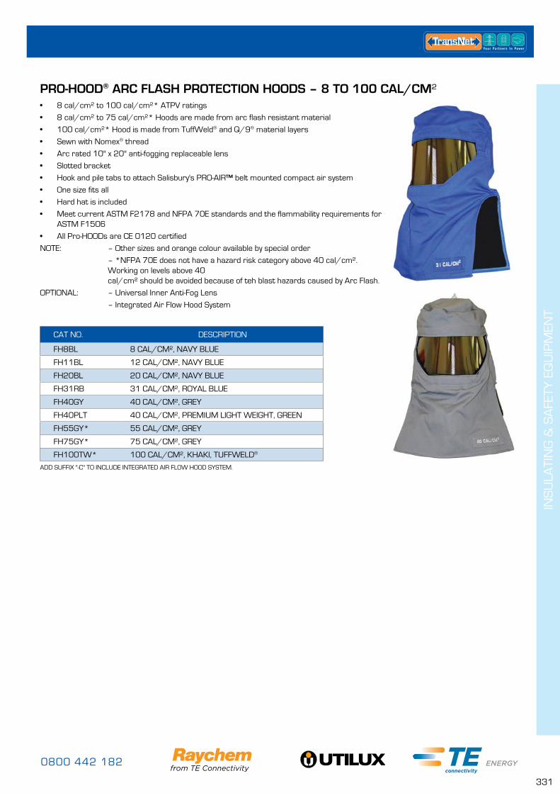
0800 442 182
331
INS
ULA
TIN
G &
SA
FETY
EQ
UIP
MEN
T
PRO-HOOD® ARC FLASH PROTECTION HOODS – 8 TO 100 CAL/CM²• 8 cal/cm² to 100 cal/cm²* ATPV ratings
• 8 cal/cm² to 75 cal/cm²* Hoods are made from arc flash resistant material
• 100 cal/cm²* Hood is made from TuffWeld® and Q/9® material layers
• Sewn with Nomex® thread
• Arc rated 10" x 20" anti-fogging replaceable lens
• Slotted bracket
• Hook and pile tabs to attach Salisbury's PRO-AIR™ belt mounted compact air system
• One size fits all
• Hard hat is included
• Meet current ASTM F2178 and NFPA 70E standards and the flammability requirements for ASTM F1506
• All Pro-HOODs are CE 0120 certified
NOTE: – Other sizes and orange colour available by special order
– *NFPA 70E does not have a hazard risk category above 40 cal/cm². Working on levels above 40 cal/cm² should be avoided because of teh blast hazards caused by Arc Flash.
OPTIONAL: – Universal Inner Anti-Fog Lens
– Integrated Air Flow Hood System
CAT NO. DESCRIPTION
FH8BL 8 CAL/CM², NAVY BLUE
FH11BL 12 CAL/CM², NAVY BLUE
FH20BL 20 CAL/CM², NAVY BLUE
FH31RB 31 CAL/CM², ROYAL BLUE
FH40GY 40 CAL/CM², GREY
FH40PLT 40 CAL/CM², PREMIUM LIGHT WEIGHT, GREEN
FH55GY* 55 CAL/CM², GREY
FH75GY* 75 CAL/CM², GREY
FH100TW* 100 CAL/CM², KHAKI, TUFFWELD®
ADD SUFFIX "-C" TO INCLUDE INTEGRATED AIR FLOW HOOD SYSTEM.
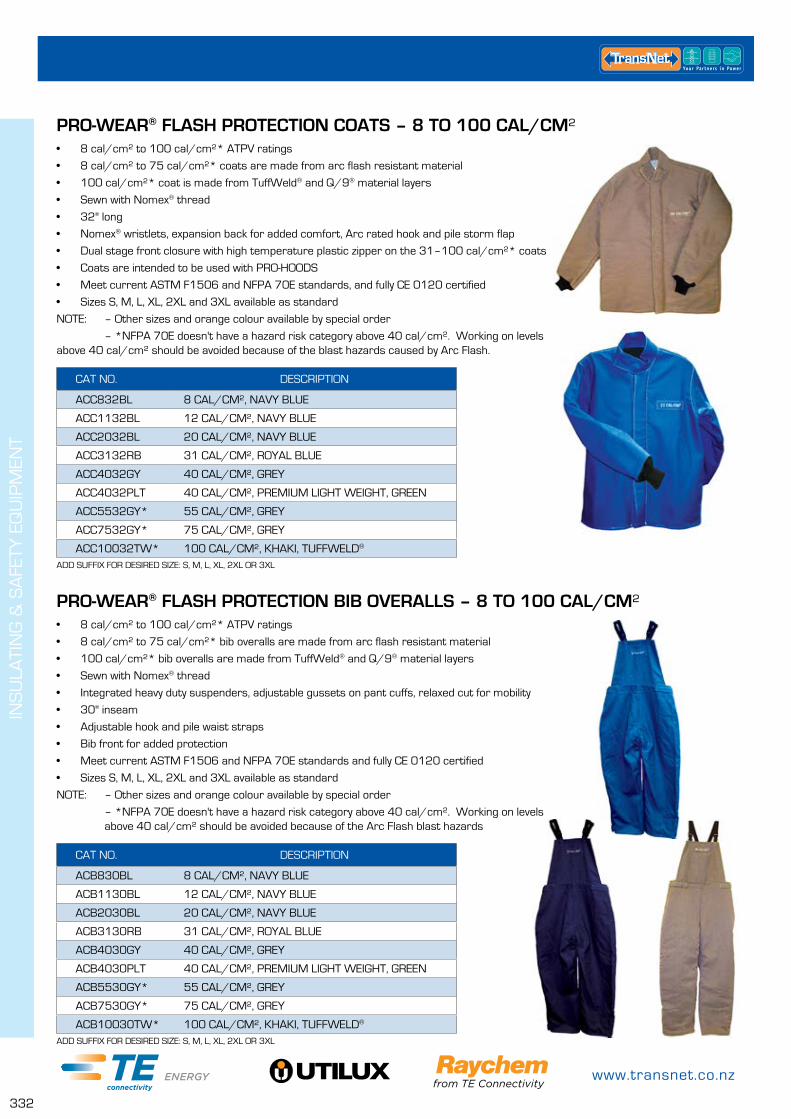
www.transnet.co.nz
332
INS
ULA
TIN
G &
SA
FETY
EQ
UIP
MEN
T
PRO-WEAR® FLASH PROTECTION COATS – 8 TO 100 CAL/CM²
PRO-WEAR® FLASH PROTECTION BIB OVERALLS – 8 TO 100 CAL/CM²
• 8 cal/cm² to 100 cal/cm²* ATPV ratings
• 8 cal/cm² to 75 cal/cm²* coats are made from arc flash resistant material
• 100 cal/cm²* coat is made from TuffWeld® and Q/9® material layers
• Sewn with Nomex® thread
• 32" long
• Nomex® wristlets, expansion back for added comfort, Arc rated hook and pile storm flap
• Dual stage front closure with high temperature plastic zipper on the 31–100 cal/cm²* coats
• Coats are intended to be used with PRO-HOODS
• Meet current ASTM F1506 and NFPA 70E standards, and fully CE 0120 certified
• Sizes S, M, L, XL, 2XL and 3XL available as standard
NOTE: – Other sizes and orange colour available by special order
– *NFPA 70E doesn't have a hazard risk category above 40 cal/cm². Working on levels above 40 cal/cm² should be avoided because of the blast hazards caused by Arc Flash.
• 8 cal/cm² to 100 cal/cm²* ATPV ratings
• 8 cal/cm² to 75 cal/cm²* bib overalls are made from arc flash resistant material
• 100 cal/cm²* bib overalls are made from TuffWeld® and Q/9® material layers
• Sewn with Nomex® thread
• Integrated heavy duty suspenders, adjustable gussets on pant cuffs, relaxed cut for mobility
• 30" inseam
• Adjustable hook and pile waist straps
• Bib front for added protection
• Meet current ASTM F1506 and NFPA 70E standards and fully CE 0120 certified
• Sizes S, M, L, XL, 2XL and 3XL available as standard
NOTE: – Other sizes and orange colour available by special order
– *NFPA 70E doesn't have a hazard risk category above 40 cal/cm². Working on levels above 40 cal/cm² should be avoided because of the Arc Flash blast hazards
CAT NO. DESCRIPTION
ACC832BL 8 CAL/CM², NAVY BLUE
ACC1132BL 12 CAL/CM², NAVY BLUE
ACC2032BL 20 CAL/CM², NAVY BLUE
ACC3132RB 31 CAL/CM², ROYAL BLUE
ACC4032GY 40 CAL/CM², GREY
ACC4032PLT 40 CAL/CM², PREMIUM LIGHT WEIGHT, GREEN
ACC5532GY* 55 CAL/CM², GREY
ACC7532GY* 75 CAL/CM², GREY
ACC10032TW* 100 CAL/CM², KHAKI, TUFFWELD®
CAT NO. DESCRIPTION
ACB830BL 8 CAL/CM², NAVY BLUE
ACB1130BL 12 CAL/CM², NAVY BLUE
ACB2030BL 20 CAL/CM², NAVY BLUE
ACB3130RB 31 CAL/CM², ROYAL BLUE
ACB4030GY 40 CAL/CM², GREY
ACB4030PLT 40 CAL/CM², PREMIUM LIGHT WEIGHT, GREEN
ACB5530GY* 55 CAL/CM², GREY
ACB7530GY* 75 CAL/CM², GREY
ACB10030TW* 100 CAL/CM², KHAKI, TUFFWELD®
ADD SUFFIX FOR DESIRED SIZE: S, M, L, XL, 2XL OR 3XL
ADD SUFFIX FOR DESIRED SIZE: S, M, L, XL, 2XL OR 3XL
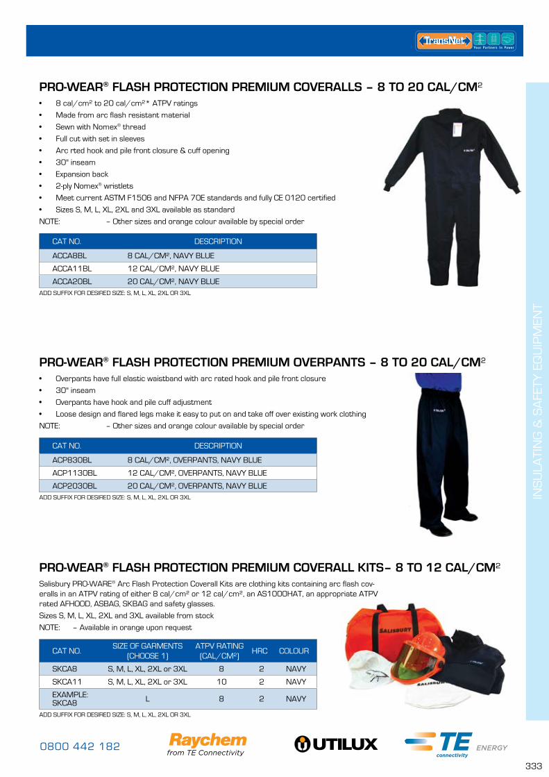
0800 442 182
333
INS
ULA
TIN
G &
SA
FETY
EQ
UIP
MEN
T
PRO-WEAR® FLASH PROTECTION PREMIUM COVERALLS – 8 TO 20 CAL/CM²• 8 cal/cm² to 20 cal/cm²* ATPV ratings
• Made from arc flash resistant material
• Sewn with Nomex® thread
• Full cut with set in sleeves
• Arc rted hook and pile front closure & cuff opening
• 30" inseam
• Expansion back
• 2-ply Nomex® wristlets
• Meet current ASTM F1506 and NFPA 70E standards and fully CE 0120 certified
• Sizes S, M, L, XL, 2XL and 3XL available as standard
NOTE: – Other sizes and orange colour available by special order
CAT NO. DESCRIPTION
ACCA8BL 8 CAL/CM², NAVY BLUE
ACCA11BL 12 CAL/CM², NAVY BLUE
ACCA20BL 20 CAL/CM², NAVY BLUEADD SUFFIX FOR DESIRED SIZE: S, M, L, XL, 2XL OR 3XL
PRO-WEAR® FLASH PROTECTION PREMIUM OVERPANTS – 8 TO 20 CAL/CM²
PRO-WEAR® FLASH PROTECTION PREMIUM COVERALL KITS– 8 TO 12 CAL/CM²
• Overpants have full elastic waistband with arc rated hook and pile front closure
• 30" inseam
• Overpants have hook and pile cuff adjustment
• Loose design and flared legs make it easy to put on and take off over existing work clothing
NOTE: – Other sizes and orange colour available by special order
Salisbury PRO-WARE® Arc Flash Protection Coverall Kits are clothing kits containing arc flash cov-eralls in an ATPV rating of either 8 cal/cm² or 12 cal/cm², an AS1000HAT, an appropriate ATPV rated AFHOOD, ASBAG, SKBAG and safety glasses.
Sizes S, M, L, XL, 2XL and 3XL available from stock
NOTE: – Available in orange upon request
CAT NO. DESCRIPTION
ACP830BL 8 CAL/CM², OVERPANTS, NAVY BLUE
ACP1130BL 12 CAL/CM², OVERPANTS, NAVY BLUE
ACP2030BL 20 CAL/CM², OVERPANTS, NAVY BLUE
CAT NO.SIZE OF GARMENTS
(CHOOSE 1)ATPV RATING
(CAL/CM²)HRC COLOUR
SKCA8 S, M, L, XL, 2XL or 3XL 8 2 NAVY
SKCA11 S, M, L, XL, 2XL or 3XL 10 2 NAVY
EXAMPLE:SKCA8 L 8 2 NAVY
ADD SUFFIX FOR DESIRED SIZE: S, M, L, XL, 2XL OR 3XL
ADD SUFFIX FOR DESIRED SIZE: S, M, L, XL, 2XL OR 3XL
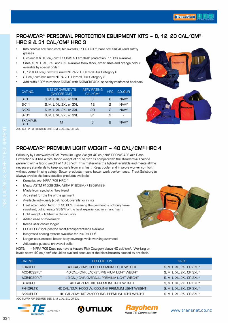
www.transnet.co.nz
334
INS
ULA
TIN
G &
SA
FETY
EQ
UIP
MEN
T
PRO-WEAR® PERSONAL PROTECTION EQUIPMENT KITS – 8, 12, 20 CAL/CM² HRC 2 & 31 CAL/CM² HRC 3• Kits contain arc flash coat, bib overalls, PRO-HOOD®, hard hat, SKBAG and safety
glasses.
• 2 colour 8 & 12 cal/cm² PRO-WEAR arc flash protection PPE kits available.
• Sizes, S, M, L, XL, 2XL and 3XL available from stock, other sizes and orange colour available by special order
• 8, 12 & 20 cal/cm² kits meet NFPA 70E Hazard Risk Category 2
• 31 cal/cm² kits meet NFPA 70E Hazard Risk Category 3
• Add suffix "-BP" to replace SKBAG with SKBACKPACK, specialty reinforced backpack
CAT NO.SIZE OF GARMENTS
(CHOOSE ONE)ATPV RATING
CAL/CM²HRC COLOUR
SK8 S, M, L, XL, 2XL or 3XL 8 2 NAVY
SK11 S, M, L, XL, 2XL or 3XL 12 2 NAVY
SK20 S, M, L, XL, 2XL or 3XL 20 2 NAVY
SK31 S, M, L, XL, 2XL or 3XL 31 3 -
EXAMPLE: SK8 M 8 2 NAVY
ADD SUFFIX FOR DESIRED SIZE: S, M, L, XL, 2XL OR 3XL
PRO-WEAR® PREMIUM LIGHT WEIGHT – 40 CAL/CM² HRC 4Salisbury by Honeywell;s NEW Premium Light Weight 40 cal/cm² PRO-WEAR® Arc Flash Protection suit has a total fabric weight of 11 oz/yd² as compared to the standard 40 calorie garment with a fabric weight of 18 oz/yd². This material is the lightest available and meets all the necessary standards to keep you safe from arc flash. Keep cooler and improve worker comfort without comprimising safety. Better products means better work performance. Trust Salisbury to always provide the best possible products available.
• Complies wth NFPA 70E HRC 4
• Meets ASTM F1506-02A, ASTM F1959M/F1959M-99
• Made from synthetic fibre blend
• Arc rated for the life of the garment
• Available individually (coat, hood, overalls) or in kits
• Heat attenuation factor of 93.20% (meaning the garment is not only flame resistant, but it resists 93.2% of the heat experienced in an arc flash).
• Light weight – lightest in the industry
• Added ease of movement
• Keeps user cooler longer
• PRO-HOOD® includes the most transparent lens available
• Integrated cooling system available for PRO-HOOD®
• Longer coat creates better body coverage while working overhead
• Adjustable gussets on overall cuffs
NOTE: – NFPA 70E Does not have a Hazard Risk Category above 40 cal/cm². Working on levels above 40 cal/cm² should be avoided because of the blast hazards caused by arc flash.
CAT NO. DESCRIPTION SIZES
FH40PLT 40 CAL/CM², HOOD, PREMIUM LIGHT WEIGHT S, M, L, XL, 2XL OR 3XL*
ACC4032PLT 40 CAL/CM², JACKET, PREMIUM LIGHT WEIGHT S, M, L, XL, 2XL OR 3XL*
ACB4030PLT 40 CAL/CM², OVERALL, PREMIUM LIGHT WEIGHT S, M, L, XL, 2XL OR 3XL*
SK40PLT 40 CAL/CM², KIT, PREMIUM LIGHT WEIGHT S, M, L, XL, 2XL OR 3XL*
FH40PLT-C 40 CAL/CM², HOOD W/COOLING, PREMIUM LIGHT WEIGHT S, M, L, XL, 2XL OR 3XL*
SK40PLT-C 40 CAL/CM², KIT W/COOLING, PREMIUM LIGHT WEIGHT S, M, L, XL, 2XL OR 3XL*ADD SUFFIX FOR DESIRED SIZE: S, M, L, XL, 2XL OR 3XL
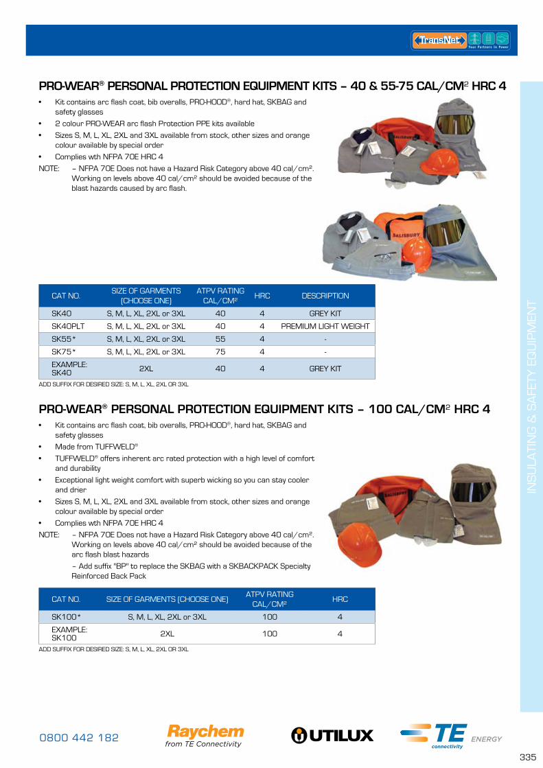
0800 442 182
335
INS
ULA
TIN
G &
SA
FETY
EQ
UIP
MEN
T
PRO-WEAR® PERSONAL PROTECTION EQUIPMENT KITS – 40 & 55-75 CAL/CM² HRC 4
PRO-WEAR® PERSONAL PROTECTION EQUIPMENT KITS – 100 CAL/CM² HRC 4
• Kit contains arc flash coat, bib overalls, PRO-HOOD®, hard hat, SKBAG and safety glasses
• 2 colour PRO-WEAR arc flash Protection PPE kits available
• Sizes S, M, L, XL, 2XL and 3XL available from stock, other sizes and orange colour available by special order
• Complies wth NFPA 70E HRC 4
NOTE: – NFPA 70E Does not have a Hazard Risk Category above 40 cal/cm². Working on levels above 40 cal/cm² should be avoided because of the blast hazards caused by arc flash.
• Kit contains arc flash coat, bib overalls, PRO-HOOD®, hard hat, SKBAG and safety glasses
• Made from TUFFWELD®
• TUFFWELD® offers inherent arc rated protection with a high level of comfort and durability
• Exceptional light weight comfort with superb wicking so you can stay cooler and drier
• Sizes S, M, L, XL, 2XL and 3XL available from stock, other sizes and orange colour available by special order
• Complies wth NFPA 70E HRC 4
NOTE: – NFPA 70E Does not have a Hazard Risk Category above 40 cal/cm². Working on levels above 40 cal/cm² should be avoided because of the arc flash blast hazards
– Add suffix "BP" to replace the SKBAG with a SKBACKPACK Specialty Reinforced Back Pack
ADD SUFFIX FOR DESIRED SIZE: S, M, L, XL, 2XL OR 3XL
ADD SUFFIX FOR DESIRED SIZE: S, M, L, XL, 2XL OR 3XL
CAT NO.SIZE OF GARMENTS
(CHOOSE ONE)ATPV RATING
CAL/CM²HRC DESCRIPTION
SK40 S, M, L, XL, 2XL or 3XL 40 4 GREY KIT
SK40PLT S, M, L, XL, 2XL or 3XL 40 4 PREMIUM LIGHT WEIGHT
SK55* S, M, L, XL, 2XL or 3XL 55 4 -
SK75* S, M, L, XL, 2XL or 3XL 75 4 -
EXAMPLE: SK40 2XL 40 4 GREY KIT
CAT NO. SIZE OF GARMENTS (CHOOSE ONE)ATPV RATING
CAL/CM²HRC
SK100* S, M, L, XL, 2XL or 3XL 100 4
EXAMPLE: SK100 2XL 100 4
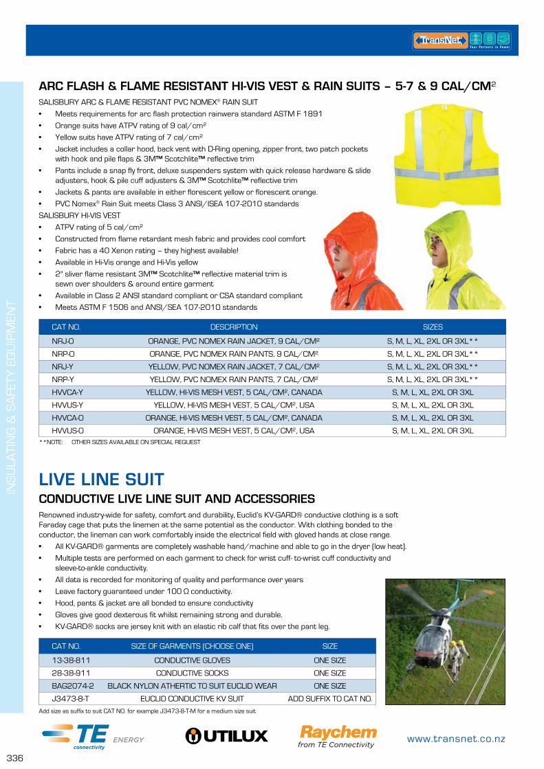
www.transnet.co.nz
336
INS
ULA
TIN
G &
SA
FETY
EQ
UIP
MEN
T
ARC FLASH & FLAME RESISTANT HI-VIS VEST & RAIN SUITS – 5-7 & 9 CAL/CM²SALISBURY ARC & FLAME RESISTANT PVC NOMEX® RAIN SUIT
• Meets requirements for arc flash protection rainwera standard ASTM F 1891
• Orange suits have ATPV rating of 9 cal/cm²
• Yellow suits have ATPV rating of 7 cal/cm²
• Jacket includes a collar hood, back vent with D-Ring opening, zipper front, two patch pockets with hook and pile flaps & 3M™ Scotchlite™ reflective trim
• Pants include a snap fly front, deluxe suspenders system with quick release hardware & slide adjusters, hook & pile cuff adjusters & 3M™ Scotchlite™ reflective trim
• Jackets & pants are available in either florescent yellow or florescent orange.
• PVC Nomex® Rain Suit meets Class 3 ANSI/ISEA 107-2010 standards
SALISBURY HI-VIS VEST
• ATPV rating of 5 cal/cm²
• Constructed from flame retardant mesh fabric and provides cool comfort
• Fabric has a 40 Xenon rating – they highest available!
• Available in Hi-Vis orange and Hi-Vis yellow
• 2" sliver flame resistant 3M™ Scotchlite™ reflective material trim is sewn over shoulders & around entire garment
• Available in Class 2 ANSI standard compliant or CSA standard compliant
• Meets ASTM F 1506 and ANSI/SEA 107-2010 standards
**NOTE: OTHER SIZES AVAILABLE ON SPECIAL REQUEST
CAT NO. DESCRIPTION SIZES
NRJ-O ORANGE, PVC NOMEX RAIN JACKET, 9 CAL/CM² S, M, L, XL, 2XL OR 3XL**
NRP-O ORANGE, PVC NOMEX RAIN PANTS, 9 CAL/CM² S, M, L, XL, 2XL OR 3XL**
NRJ-Y YELLOW, PVC NOMEX RAIN JACKET, 7 CAL/CM² S, M, L, XL, 2XL OR 3XL**
NRP-Y YELLOW, PVC NOMEX RAIN PANTS, 7 CAL/CM² S, M, L, XL, 2XL OR 3XL**
HVVCA-Y YELLOW, HI-VIS MESH VEST, 5 CAL/CM², CANADA S, M, L, XL, 2XL OR 3XL
HVVUS-Y YELLOW, HI-VIS MESH VEST, 5 CAL/CM², USA S, M, L, XL, 2XL OR 3XL
HVVCA-O ORANGE, HI-VIS MESH VEST, 5 CAL/CM², CANADA S, M, L, XL, 2XL OR 3XL
HVVUS-O ORANGE, HI-VIS MESH VEST, 5 CAL/CM², USA S, M, L, XL, 2XL OR 3XL
Add size as suffix to suit CAT NO. for example J3473-8-T-M for a medium size suit
LIVE LINE SUITCONDUCTIVE LIVE LINE SUIT AND ACCESSORIESRenowned industry-wide for safety, comfort and durability, Euclid’s KV-GARD® conductive clothing is a soft Faraday cage that puts the linemen at the same potential as the conductor. With clothing bonded to the conductor, the lineman can work comfortably inside the electrical field with gloved hands at close range.
• All KV-GARD® garments are completely washable hand/machine and able to go in the dryer (low heat).
• Multiple tests are performed on each garment to check for wrist cuff- to-wrist cuff conductivity and sleeve-to-ankle conductivity.
• All data is recorded for monitoring of quality and performance over years
• Leave factory guaranteed under 100 Ω conductivity.
• Hood, pants & jacket are all bonded to ensure conductivity
• Gloves give good dexterous fit whilst remaining strong and durable.
• KV-GARD® socks are jersey knit with an elastic rib calf that fits over the pant leg.
CAT NO. SIZE OF GARMENTS (CHOOSE ONE) SIZE
13-38-811 CONDUCTIVE GLOVES ONE SIZE
28-38-911 CONDUCTIVE SOCKS ONE SIZE
BAG2074-2 BLACK NYLON ATHERTIC TO SUIT EUCLID WEAR ONE SIZE
J3473-8-T EUCLID CONDUCTIVE KV SUIT ADD SUFFIX TO CAT NO.
0800 442 182
337
ECO
LIG
HT
LED
FLO
OD
LIG
HTS
LED FLOOD LIGHTS PAGE
LEDFL11– 25W & 40W Flood Light 338
LEDFL17 – 70W Flood Light 338
LEDFL18 – 140W Flood Light 339
LEDiFL19 – 15W, 100W, 160W Flood Light 339
ECOLIGHT LED FLOOD LIGHTS

www.transnet.co.nz
338
The LEDFL11 flood light is the light of choice for most general purpose domestic and commercial applications.
Made from a powder coated Aluminium housing, with a frosted toughened glass lens and stainless steel fasteners, the LEDFL11 is a robust LED flood light made to withstand tough environmental conditions. DC versions offer flexibility for different applications. Alternative mounting options such as cable tray make for a fast effective installation. A range of options make this model a versatile option for many applications.
FEATURES• IP65 rated
• >50,000hr service life
• No UV, IR, Lead or Mercury in this product
• 316 Stainless Steel fasteners
• Weight = 3.3kg
• Dimensions = 262x185x163mm
LED FLOOD LIGHT 70W – LEDFL17
* AC Current rating at 230V AC
The slim profile is excellent for locations where roof heights are at a minimum, and traditional high bays will not fit. It’s also popular as security and yard lighting for commercial and industrial buildings.
FEATURES• IP65 rated
• >50,000hr service life
• No UV, IR, Lead or Mercury in this product
• 316 Stainless Steel fasteners
• Weight = 7.39kg
• Dimensions = 368x285x93mm
CAT NO. FEATURE LUMENS POWER CURRENT SUPPLY VOLTAGE
LEDFL17-70AC COOL WHITE COLOUR 7200 70W 0.32A* 85 ~ 265V AC
LEDFL17-70ACWW WARM WHITE COLOUR 7200 70W 0.32A* 85 ~ 265V AC
LEDFL17-70DC24 DC VOLTAGE 7200 70W 3.16A 24V DC
LEDFL17-70PC POLYCARBONATE LENS 7200 70W 0.32A* 85 ~ 265V AC
LEDFL17-70FG FROSTED GLASS LENS 7200 70W 0.32A* 85 ~ 265V AC
ECO
LIG
HT
LED
FLO
OD
LIG
HTS
LED FLOOD LIGHTSLED FLOOD LIGHT 25W & 40W – LEDFL11
CAT NO. LENS LUMENS POWER CURRENT SUPPLY VOLTAGE
LEDFL11-25AC
TOUGHENED GLASS 2250 25W
0.12A* 85~265V ACLEDFL11-25AC
LEDFL11-25DC12 2.25A 12V DC
LEDFL11-25DC24 1.13A 24V DC
LEDFL11-40AC
TOUGHENED GLASS 3600 40W
0.18A* 85~265V ACLEDFL11-40ACWW
LEDFL11-40DC12 3.58A 12V DC
LEDFL11-40DC24 1.79A 24V DC

0800 442 182
339
LED FLOOD LIGHT 140W – LEDFL18
LED FLOOD LIGHT 15W, 100W & 160W – LEDIFL19
CAT NO. LENS LUMENS CURRENT SUPPLY VOLTAGE
LEDFL18-140AC TOUGHENED GLASS 11,700 0.47A* 85 ~ 265V AC
LEDFL18-140ACWW TOUGHENED GLASS 11,700 0.47A* 85 ~ 265V AC
LEDFL18-140PC POLYCARBONATE 11,700 0.47A* 85 ~ 265V AC
LEDFL18-140DC24 TOUGHENED GLASS 11,700 6.72A 24V DC
CAT NO. LENS LED LUMENS WEIGHT (kg) SUPPLY VOLTAGE
LEDIFL19-15AC TOUGHENED GLASS 1275 0.71 85 ~ 265V AC
LEDIFL19-100AC TOUGHENED GLASS 8,500 6.00 85 ~ 265V AC
LEDIFL19N-160ACTOUGHENED GLASS 13,600 12.40 85 ~ 265V AC
LEDIFL19W-160AC
* AC Current rating at 230V AC
A high quality professional looking light suitable for both indoor and outdoor applications. The slim profile is excellent for locations where roof heights are at a minimum, and traditional high bays will not fit, also popular as security and yard lighting outside large commercial and industrial buildings.
FEATURES• IP65 rated
• >50,000hr service life
• No UV, IR, Lead or Mercury in this product
• 316 Stainless Steel fasteners
• Weight = 10.6kg
• Dimensions = 568x285x93mm
The LEDIFL19 range of fittings are a true industrial grade LED solution.
This is a IP65 rated fitting that includes LM06 aluminium housing and dual layer anti-corrosion powder coat finish it can be relied upon in the harshest of conditions.
This also comes with an anti-glare tempered glass frosted lens and has fantastic light output. This is ideal for a number of different applications including floodlighting, high bay and with the narrow beam angle it makes for the ideal spotlight and tower lighting applications. The bracket includes an easy to use adjustable pivot to enable very precise angle placement.
ECO
LIG
HT
LED
FLO
OD
LIG
HTS
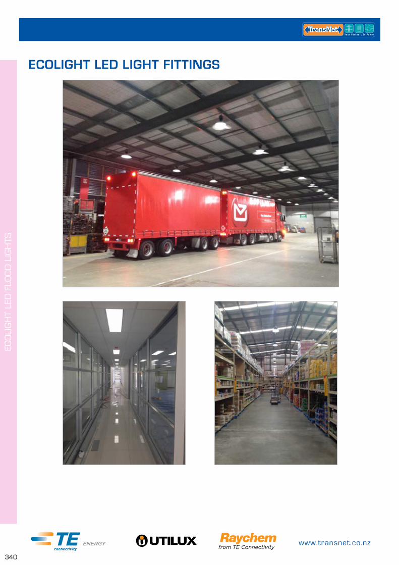
www.transnet.co.nz
340
ECO
LIG
HT
LED
FLO
OD
LIG
HTS
ECOLIGHT LED LIGHT FITTINGS
0800 442 182
341
REF
EREN
CE
TAB
LES
CONDUCTOR REFERENCE TABLES PAGE
Conversion Tables for Non-Metric Cable Sizes 342
Cable Cross Sections – Annealed Aluminium and Copper Stranded Conductors 343
Overhead Conductors 344
Stranded Hard Drawn Copper Conductor Sizes – Metric and Imperial 345
Nominal Cross Sectional Area mm² 346
Aluminium Conductor (Galvanised) Steel Reinforced ACSR/GZ/1350 Australian Standard – AS 3607 347
Aluminium Conductor (Aluminised) Steel Reinforced ACSR/AZ/1350 Australian Standard – AS 3607 347
Aluminium Conductor (Aluminium Clad) Steel Reinforced ACSR/AC/1350 Australian Standard – AS 3607 348
Aluminium Conductor (Aluminised) Steel Reinforced ACSR/GZ/1350 Australian Standard – AS 3607 Extra High Strength
348
Aluminium Conductor AAC/1350 Australian Standard – AS 1531 349
All Aluminium Conductor AAAC 6201 Australian Standard – AS 1531 349
All Aluminium Alloy Conductor AAAC 1120 Australian Standard – AS 1531 350
Steel Conductor/Galvanised SC/GZ Australian Standard – AS 1222 Part 1 350
Hard Drawn Copper Conductor HDC Australian Standard – AS 1746 351
REFERENCE TABLES
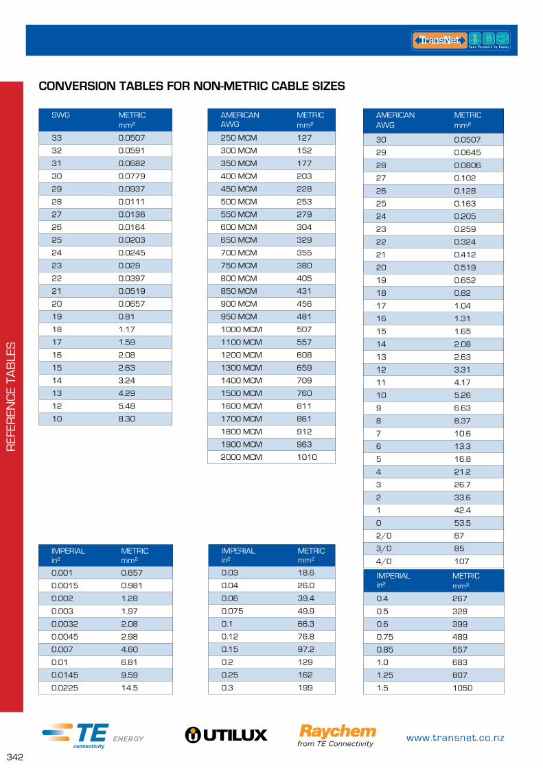
www.transnet.co.nz
342
REF
EREN
CE
TAB
LES
CONVERSION TABLES FOR NON-METRIC CABLE SIZES
IMPERIAL in²
METRIC mm²
0.001 0.657
0.0015 0.981
0.002 1.28
0.003 1.97
0.0032 2.08
0.0045 2.98
0.007 4.60
0.01 6.81
0.0145 9.59
0.0225 14.5
IMPERIAL in²
METRIC mm²
0.03 18.6
0.04 26.0
0.06 39.4
0.075 49.9
0.1 66.3
0.12 76.8
0.15 97.2
0.2 129
0.25 162
0.3 199
SWG METRIC mm²
33 0.0507
32 0.0591
31 0.0682
30 0.0779
29 0.0937
28 0.0111
27 0.0136
26 0.0164
25 0.0203
24 0.0245
23 0.029
22 0.0397
21 0.0519
20 0.0657
19 0.81
18 1.17
17 1.59
16 2.08
15 2.63
14 3.24
13 4.29
12 5.48
10 8.30
AMERICAN AWG
METRICmm²
30 0.0507
29 0.0645
28 0.0806
27 0.102
26 0.128
25 0.163
24 0.205
23 0.259
22 0.324
21 0.412
20 0.519
19 0.652
18 0.82
17 1.04
16 1.31
15 1.65
14 2.08
13 2.63
12 3.31
11 4.17
10 5.26
9 6.63
8 8.37
7 10.6
6 13.3
5 16.8
4 21.2
3 26.7
2 33.6
1 42.4
0 53.5
2/0 67
3/0 85
4/0 107
IMPERIAL in²
METRIC mm²
0.4 267
0.5 328
0.6 399
0.75 489
0.85 557
1.0 683
1.25 807
1.5 1050
AMERICAN AWG
METRIC mm²
250 MCM 127
300 MCM 152
350 MCM 177
400 MCM 203
450 MCM 228
500 MCM 253
550 MCM 279
600 MCM 304
650 MCM 329
700 MCM 355
750 MCM 380
800 MCM 405
850 MCM 431
900 MCM 456
950 MCM 481
1000 MCM 507
1100 MCM 557
1200 MCM 608
1300 MCM 659
1400 MCM 709
1500 MCM 760
1600 MCM 811
1700 MCM 861
1800 MCM 912
1900 MCM 963
2000 MCM 1010
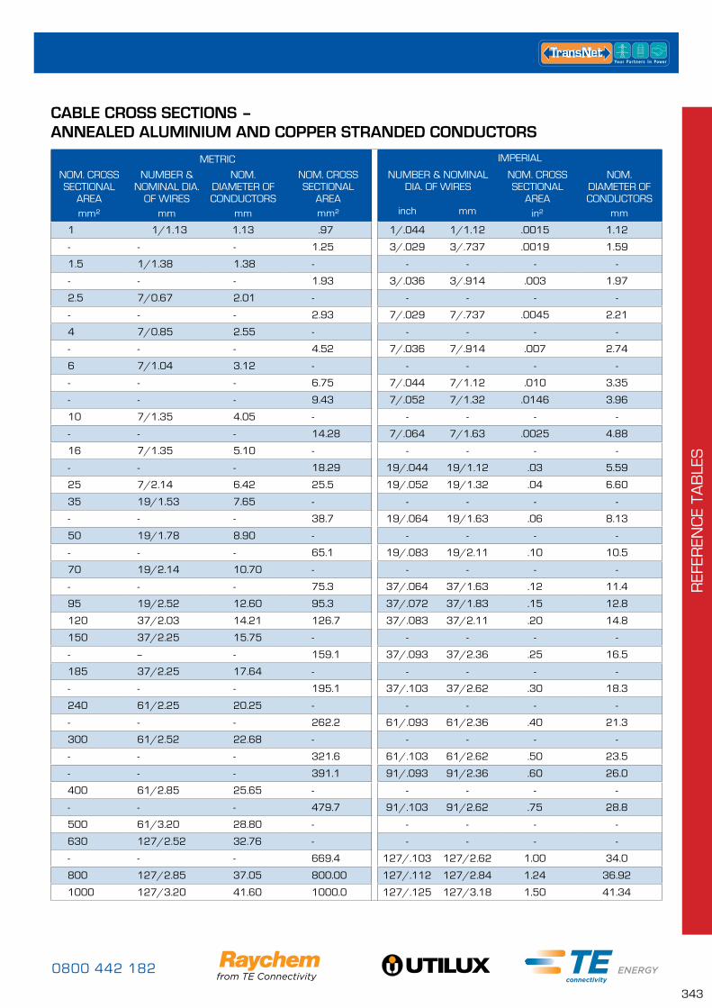
0800 442 182
343
REF
EREN
CE
TAB
LES
CABLE CROSS SECTIONS – ANNEALED ALUMINIUM AND COPPER STRANDED CONDUCTORS
mm
NOMINAL DIA. OF
CONDUCTORmm
NOMINALCROSS
SECTIONALAREA
Inches²
METRIC IMPERIAL
NOM. CROSS SECTIONAL
AREA mm²
NUMBER & NOMINAL DIA.
OF WIRESmm
NOM. DIAMETER OF CONDUCTORS
mm
NOM. CROSS SECTIONAL
AREA mm²
NUMBER & NOMINAL DIA. OF WIRES
NOM. CROSS SECTIONAL
AREA in²
NOM. DIAMETER OF CONDUCTORS
mminch mm
1 1/1.13 1.13 .97 1/.044 1/1.12 .0015 1.12
- - - 1.25 3/.029 3/.737 .0019 1.59
1.5 1/1.38 1.38 - - - - -
- - - 1.93 3/.036 3/.914 .003 1.97
2.5 7/0.67 2.01 - - - - -
- - - 2.93 7/.029 7/.737 .0045 2.21
4 7/0.85 2.55 - - - - -
- - - 4.52 7/.036 7/.914 .007 2.74
6 7/1.04 3.12 - - - - -
- - - 6.75 7/.044 7/1.12 .010 3.35
- - - 9.43 7/.052 7/1.32 .0146 3.96
10 7/1.35 4.05 - - - - -
- - - 14.28 7/.064 7/1.63 .0025 4.88
16 7/1.35 5.10 - - - - -
- - - 18.29 19/.044 19/1.12 .03 5.59
25 7/2.14 6.42 25.5 19/.052 19/1.32 .04 6.60
35 19/1.53 7.65 - - - - -
- - - 38.7 19/.064 19/1.63 .06 8.13
50 19/1.78 8.90 - - - - -
- - - 65.1 19/.083 19/2.11 .10 10.5
70 19/2.14 10.70 - - - - -
- - - 75.3 37/.064 37/1.63 .12 11.4
95 19/2.52 12.60 95.3 37/.072 37/1.83 .15 12.8
120 37/2.03 14.21 126.7 37/.083 37/2.11 .20 14.8
150 37/2.25 15.75 - - - - -
- -- - 159.1 37/.093 37/2.36 .25 16.5
185 37/2.25 17.64 - - - - -
- - - 195.1 37/.103 37/2.62 .30 18.3
240 61/2.25 20.25 - - - - -
- - - 262.2 61/.093 61/2.36 .40 21.3
300 61/2.52 22.68 - - - - -
- - - 321.6 61/.103 61/2.62 .50 23.5
- - - 391.1 91/.093 91/2.36 .60 26.0
400 61/2.85 25.65 - - - - -
- - - 479.7 91/.103 91/2.62 .75 28.8
500 61/3.20 28.80 - - - - -
630 127/2.52 32.76 - - - - -
- - - 669.4 127/.103 127/2.62 1.00 34.0
800 127/2.85 37.05 800.00 127/.112 127/2.84 1.24 36.92
1000 127/3.20 41.60 1000.0 127/.125 127/3.18 1.50 41.34
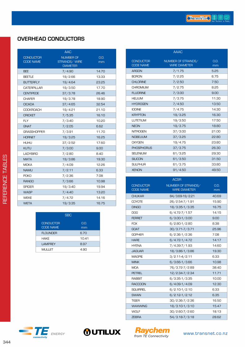
www.transnet.co.nz
344
REF
EREN
CE
TAB
LES
OVERHEAD CONDUCTORS
AAC
CONDUCTORCODE NAME
NUMBER OF STRANDS/ WIRE
DIAMETER
O.D.mm
BEE 7/4.90 14.70
BEETLE 19/2.66 13.33
BUTTERFLY 19/4.64 23.25
CATERPILLAR 19/3.50 17.70
CENTIPEDE 37/3.78 26.46
CHAFER 19/3.78 18.90
CICADA 37/4.65 32.54
COCKROACH 19/4.21 21.10
CRICKET 7/5.35 16.10
FLY 7/3.40 10.20
GNAT 7/2.05 6.62
GRASSHOPPER 7/3.91 11.70
HORNET 19/3.25 16.25
HUHU 37/2.52 17.60
KUTU 7/3.00 9.00
LADYBIRD 7/2.80 8.40
MATA 19/3.86 19.30
MOKA 7/4.09 12.26
NAMU 7/2.11 6.33
POKO 7/2.36 7.08
RANGO 7/3.66 10.98
SPIDER 19/3.40 19.94
WASP 7/4.40 13.20
WEKE 7/4.72 14.16
WETA 19/3.35 16.75
AAAC
CONDUCTORCODE NAME
NUMBER OF STRANDS/ WIRE DIAMETER
O.D.mm
ARGON 7/1.75 5.25
BORON 7/2.25 6.75
CHLORINE 7/2.50 7.50
CHROMIUM 7/2.75 8.25
FLUORINE 7/3.00 9.00
HELIUM 7/3.75 11.30
HYDROGEN 7/4.50 13.50
IODINE 7/4.75 14.30
KRYPTON 19/3.25 16.30
LUTETIUM 19/3.50 17.50
NEON 19/3.75 18.80
NITROGEN 37/3.00 21.00
NOBELIUM 37/3.25 22.80
OXYGEN 19/4.75 23.80
PHOSPHORUS 37/3.75 26.30
SELENIUM 61/3.25 29.30
SILICON 61/3.50 31.50
SULPHUR 61/3.75 33.80
XENON 91/4.50 49.50
ACSR
CONDUCTORCODE NAME
NUMBER OF STRANDS/ WIRE DIAMETER
O.D.mm
CHUKAR 84/3.69-19/2.21 40.69
COYOTE 26/2.54-7/1.91 15.90
DINGO 18/3.35-1/3.35 16.75
DOG 6/4.72-7/1.57 14.15
FERRET 6/3.00-1/3.00 9.00
FOX 6/2.80-1/2.80 8.38
GOAT 30/3.71-7/3.71 25.96
GOPHER 6/2.36-1/2.36 7.08
HARE 6/4.72-1/4.72 14.17
HYENA 7/4.39-7/1.93 14.60
JAGUAR 18/3.86-1/3.86 19.30
MAGPIE 3/2.11-4/2.11 6.33
MINK 6/3.66-1/3.66 10.98
MOA 76/3.72-7/2.89 38.40
PETREL 12/2.34-7/2.34 11.71
RABBIT 6/3.35-1/3.35 10.00
RACCOON 6/4.09-1/4.09 12.30
SQUIRREL 6/2.10-1/2.10 6.33
SWAN 6/2.12-1/2.12 6.35
TIGER 30/2.36-7/2.36 16.50
WAXWING 18/3.10-1/3.10 15.47
WOLF 30/2.60-7/2.60 18.13
ZEBRA 54/3.18-7/3.18 28.62
SBC
CONDUCTORCODE NAME
O.D.mm
FLOUNDER 6.70
HAKE 10.41
LAMPREY 8.97
MULLET 4.90
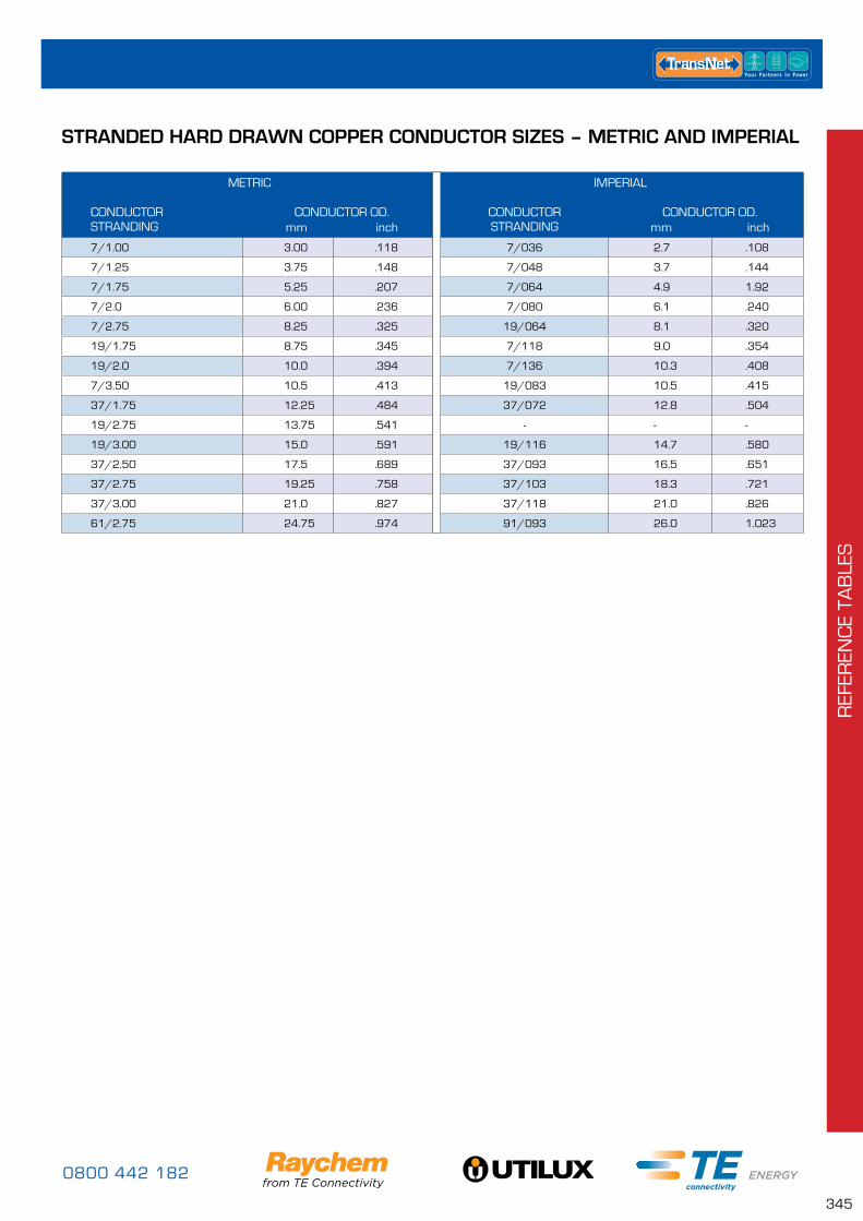
0800 442 182
345
REF
EREN
CE
TAB
LES
STRANDED HARD DRAWN COPPER CONDUCTOR SIZES – METRIC AND IMPERIAL
METRIC IMPERIAL
CONDUCTOR STRANDING
CONDUCTOR OD. mm inch
CONDUCTOR STRANDING
CONDUCTOR OD. mm inch
7/1.00 3.00 .118 7/036 2.7 .108
7/1.25 3.75 .148 7/048 3.7 .144
7/1.75 5.25 .207 7/064 4.9 1.92
7/2.0 6.00 .236 7/080 6.1 .240
7/2.75 8.25 .325 19/064 8.1 .320
19/1.75 8.75 .345 7/118 9.0 .354
19/2.0 10.0 .394 7/136 10.3 .408
7/3.50 10.5 .413 19/083 10.5 .415
37/1.75 12.25 .484 37/072 12.8 .504
19/2.75 13.75 .541 - - -
19/3.00 15.0 .591 19/116 14.7 .580
37/2.50 17.5 .689 37/093 16.5 .651
37/2.75 19.25 .758 37/103 18.3 .721
37/3.00 21.0 .827 37/118 21.0 .826
61/2.75 24.75 .974 91/093 26.0 1.023
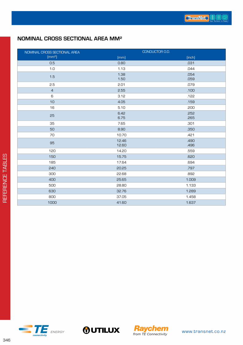
www.transnet.co.nz
346
REF
EREN
CE
TAB
LES
NOMINAL CROSS SECTIONAL AREA MM²
NOMINAL CROSS SECTIONAL AREA (mm²)
CONDUCTOR O.D.
(mm) (inch)
0.5 0.80 .031
1.0 1.13 .044
1.51.381.50
.054
.059
2.5 2.01 .079
4 2.55 .100
6 3.12 .122
10 4.05 .159
16 5.10 .200
256.426.75
.252
.265
35 7.65 .301
50 8.90 .350
70 10.70 .421
9512.4612.60
.490
.496
120 14.20 .559
150 15.75 .620
185 17.64 .694
240 20.25 .797
300 22.68 .892
400 25.65 1.009
500 28.80 1.133
630 32.76 1.289
800 37.05 1.458
1000 41.60 1.637
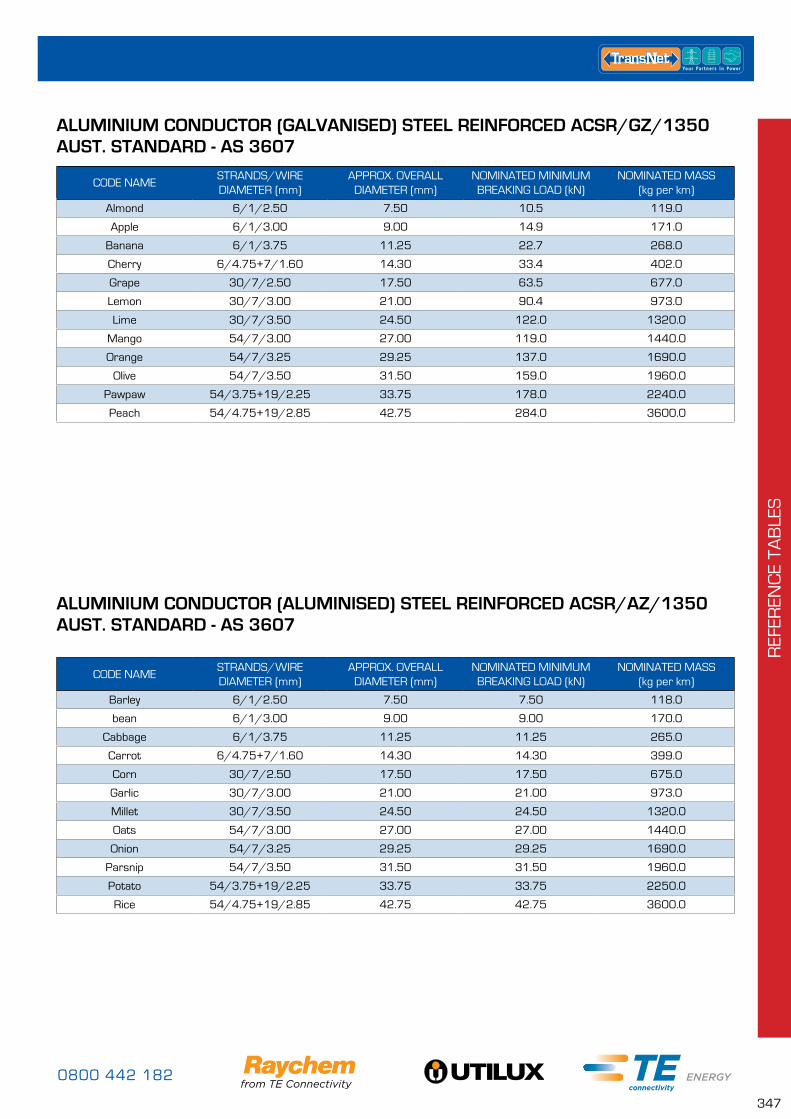
0800 442 182
347
REF
EREN
CE
TAB
LES
CODE NAMESTRANDS/WIRE DIAMETER (mm)
APPROX. OVERALL DIAMETER (mm)
NOMINATED MINIMUM BREAKING LOAD (kN)
NOMINATED MASS (kg per km)
Almond 6/1/2.50 7.50 10.5 119.0
Apple 6/1/3.00 9.00 14.9 171.0
Banana 6/1/3.75 11.25 22.7 268.0
Cherry 6/4.75+7/1.60 14.30 33.4 402.0
Grape 30/7/2.50 17.50 63.5 677.0
Lemon 30/7/3.00 21.00 90.4 973.0
Lime 30/7/3.50 24.50 122.0 1320.0
Mango 54/7/3.00 27.00 119.0 1440.0
Orange 54/7/3.25 29.25 137.0 1690.0
Olive 54/7/3.50 31.50 159.0 1960.0
Pawpaw 54/3.75+19/2.25 33.75 178.0 2240.0
Peach 54/4.75+19/2.85 42.75 284.0 3600.0
ALUMINIUM CONDUCTOR (GALVANISED) STEEL REINFORCED ACSR/GZ/1350 AUST. STANDARD - AS 3607
CODE NAMESTRANDS/WIRE DIAMETER (mm)
APPROX. OVERALL DIAMETER (mm)
NOMINATED MINIMUM BREAKING LOAD (kN)
NOMINATED MASS (kg per km)
Barley 6/1/2.50 7.50 7.50 118.0
bean 6/1/3.00 9.00 9.00 170.0
Cabbage 6/1/3.75 11.25 11.25 265.0
Carrot 6/4.75+7/1.60 14.30 14.30 399.0
Corn 30/7/2.50 17.50 17.50 675.0
Garlic 30/7/3.00 21.00 21.00 973.0
Millet 30/7/3.50 24.50 24.50 1320.0
Oats 54/7/3.00 27.00 27.00 1440.0
Onion 54/7/3.25 29.25 29.25 1690.0
Parsnip 54/7/3.50 31.50 31.50 1960.0
Potato 54/3.75+19/2.25 33.75 33.75 2250.0
Rice 54/4.75+19/2.85 42.75 42.75 3600.0
ALUMINIUM CONDUCTOR (ALUMINISED) STEEL REINFORCED ACSR/AZ/1350 AUST. STANDARD - AS 3607
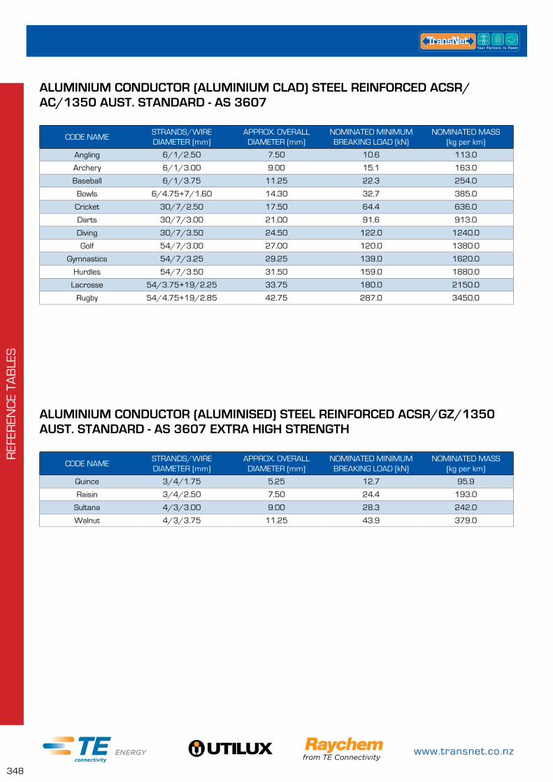
www.transnet.co.nz
348
REF
EREN
CE
TAB
LES
CODE NAMESTRANDS/WIRE DIAMETER (mm)
APPROX. OVERALL DIAMETER (mm)
NOMINATED MINIMUM BREAKING LOAD (kN)
NOMINATED MASS (kg per km)
Angling 6/1/2.50 7.50 10.6 113.0
Archery 6/1/3.00 9.00 15.1 163.0
Baseball 6/1/3.75 11.25 22.3 254.0
Bowls 6/4.75+7/1.60 14.30 32.7 385.0
Cricket 30/7/2.50 17.50 64.4 636.0
Darts 30/7/3.00 21.00 91.6 913.0
Diving 30/7/3.50 24.50 122.0 1240.0
Golf 54/7/3.00 27.00 120.0 1380.0
Gymnastics 54/7/3.25 29.25 139.0 1620.0
Hurdles 54/7/3.50 31.50 159.0 1880.0
Lacrosse 54/3.75+19/2.25 33.75 180.0 2150.0
Rugby 54/4.75+19/2.85 42.75 287.0 3450.0
ALUMINIUM CONDUCTOR (ALUMINIUM CLAD) STEEL REINFORCED ACSR/AC/1350 AUST. STANDARD - AS 3607
CODE NAMESTRANDS/WIRE DIAMETER (mm)
APPROX. OVERALL DIAMETER (mm)
NOMINATED MINIMUM BREAKING LOAD (kN)
NOMINATED MASS (kg per km)
Quince 3/4/1.75 5.25 12.7 95.9
Raisin 3/4/2.50 7.50 24.4 193.0
Sultana 4/3/3.00 9.00 28.3 242.0
Walnut 4/3/3.75 11.25 43.9 379.0
ALUMINIUM CONDUCTOR (ALUMINISED) STEEL REINFORCED ACSR/GZ/1350 AUST. STANDARD - AS 3607 EXTRA HIGH STRENGTH
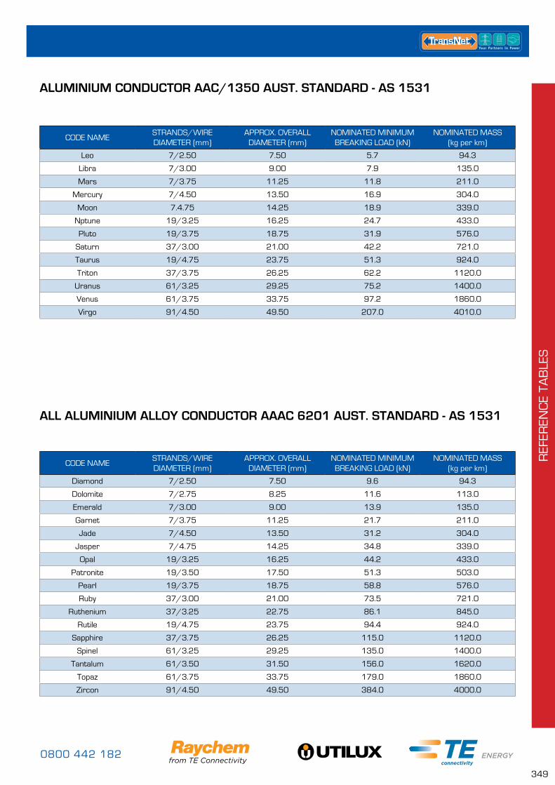
0800 442 182
349
REF
EREN
CE
TAB
LES
CODE NAMESTRANDS/WIRE DIAMETER (mm)
APPROX. OVERALL DIAMETER (mm)
NOMINATED MINIMUM BREAKING LOAD (kN)
NOMINATED MASS (kg per km)
Leo 7/2.50 7.50 5.7 94.3
Libra 7/3.00 9.00 7.9 135.0
Mars 7/3.75 11.25 11.8 211.0
Mercury 7/4.50 13.50 16.9 304.0
Moon 7.4.75 14.25 18.9 339.0
Nptune 19/3.25 16.25 24.7 433.0
Pluto 19/3.75 18.75 31.9 576.0
Saturn 37/3.00 21.00 42.2 721.0
Taurus 19/4.75 23.75 51.3 924.0
Triton 37/3.75 26.25 62.2 1120.0
Uranus 61/3.25 29.25 75.2 1400.0
Venus 61/3.75 33.75 97.2 1860.0
Virgo 91/4.50 49.50 207.0 4010.0
ALUMINIUM CONDUCTOR AAC/1350 AUST. STANDARD - AS 1531
CODE NAMESTRANDS/WIRE DIAMETER (mm)
APPROX. OVERALL DIAMETER (mm)
NOMINATED MINIMUM BREAKING LOAD (kN)
NOMINATED MASS (kg per km)
Diamond 7/2.50 7.50 9.6 94.3
Dolomite 7/2.75 8.25 11.6 113.0
Emerald 7/3.00 9.00 13.9 135.0
Garnet 7/3.75 11.25 21.7 211.0
Jade 7/4.50 13.50 31.2 304.0
Jasper 7/4.75 14.25 34.8 339.0
Opal 19/3.25 16.25 44.2 433.0
Patronite 19/3.50 17.50 51.3 503.0
Pearl 19/3.75 18.75 58.8 576.0
Ruby 37/3.00 21.00 73.5 721.0
Ruthenium 37/3.25 22.75 86.1 845.0
Rutile 19/4.75 23.75 94.4 924.0
Sapphire 37/3.75 26.25 115.0 1120.0
Spinel 61/3.25 29.25 135.0 1400.0
Tantalum 61/3.50 31.50 156.0 1620.0
Topaz 61/3.75 33.75 179.0 1860.0
Zircon 91/4.50 49.50 384.0 4000.0
ALL ALUMINIUM ALLOY CONDUCTOR AAAC 6201 AUST. STANDARD - AS 1531
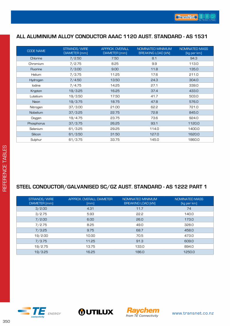
www.transnet.co.nz
350
REF
EREN
CE
TAB
LES
CODE NAMESTRANDS/WIRE DIAMETER (mm)
APPROX. OVERALL DIAMETER (mm)
NOMINATED MINIMUM BREAKING LOAD (kN)
NOMINATED MASS (kg per km)
Chlorine 7/2.50 7.50 8.1 94.3
Chromium 7/2.75 8.25 9.9 113.0
Fluorine 7/3.00 9.00 11.8 135.0
Helium 7/3.75 11.25 17.6 211.0
Hydrogen 7/4.50 13.50 24.3 304.0
Iodine 7/4.75 14.25 27.1 339.0
Krypton 19/3.25 16.25 37.4 433.0
Lutetium 19/3.50 17.50 41.7 503.0
Neon 19/3.75 18.75 47.8 576.0
Nitrogen 37/3.00 21.00 62.2 721.0
Nobelium 37/3.25 22.75 72.8 845.0
Oxygen 19/4.75 23.75 73.6 924.0
Phosphorus 37/3.75 26.25 93.1 1120.0
Selenium 61/3.25 29.25 114.0 1400.0
Silicon 61/3.50 31.50 127.0 1620.0
Sulphur 61/3.75 33.75 145.0 1860.0
ALL ALUMINIUM ALLOY CONDUCTOR AAAC 1120 AUST. STANDARD - AS 1531
STRANDS/WIRE DIAMETER (mm)
APPROX. OVERALL DIAMETER (mm)
NOMINATED MINIMUM BREAKING LOAD (kN)
NOMINATED MASS (kg per km)
3/2.00 4.31 11.7 74
3/2.75 5.93 22.2 140.0
7/2.00 6.00 26.0 173.0
7/2.75 8.25 49.0 328.0
7/3.25 9.75 68.7 458.0
19/2.00 10.00 70.5 473.0
7/3.75 11.25 91.3 609.0
19/2.75 13.75 133.0 894.0
19/3.25 16.25 186.0 1250.0
STEEL CONDUCTOR/GALVANISED SC/GZ AUST. STANDARD - AS 1222 PART 1
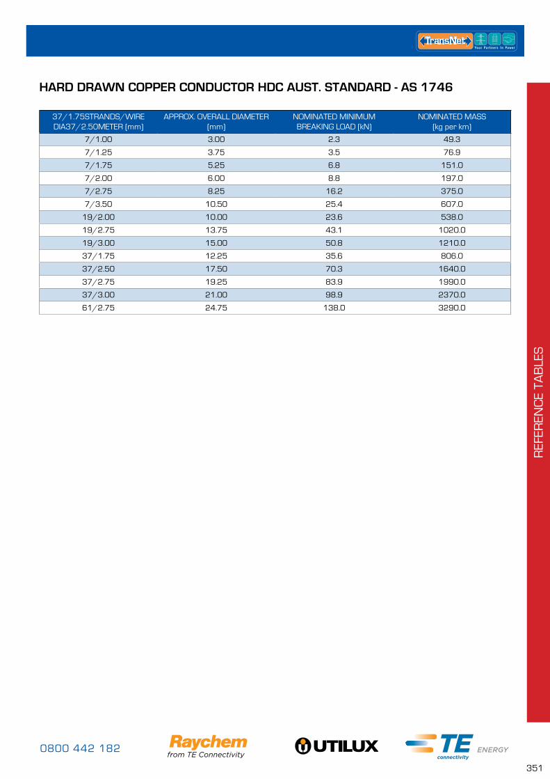
0800 442 182
351
REF
EREN
CE
TAB
LES
37/1.75STRANDS/WIRE DIA37/2.50METER (mm)
APPROX. OVERALL DIAMETER (mm)
NOMINATED MINIMUM BREAKING LOAD (kN)
NOMINATED MASS (kg per km)
7/1.00 3.00 2.3 49.3
7/1.25 3.75 3.5 76.9
7/1.75 5.25 6.8 151.0
7/2.00 6.00 8.8 197.0
7/2.75 8.25 16.2 375.0
7/3.50 10.50 25.4 607.0
19/2.00 10.00 23.6 538.0
19/2.75 13.75 43.1 1020.0
19/3.00 15.00 50.8 1210.0
37/1.75 12.25 35.6 806.0
37/2.50 17.50 70.3 1640.0
37/2.75 19.25 83.9 1990.0
37/3.00 21.00 98.9 2370.0
61/2.75 24.75 138.0 3290.0
HARD DRAWN COPPER CONDUCTOR HDC AUST. STANDARD - AS 1746
www.transnet.co.nz
352
REF
EREN
CE
TAB
LES
RAYCHEM KITTING ROOM
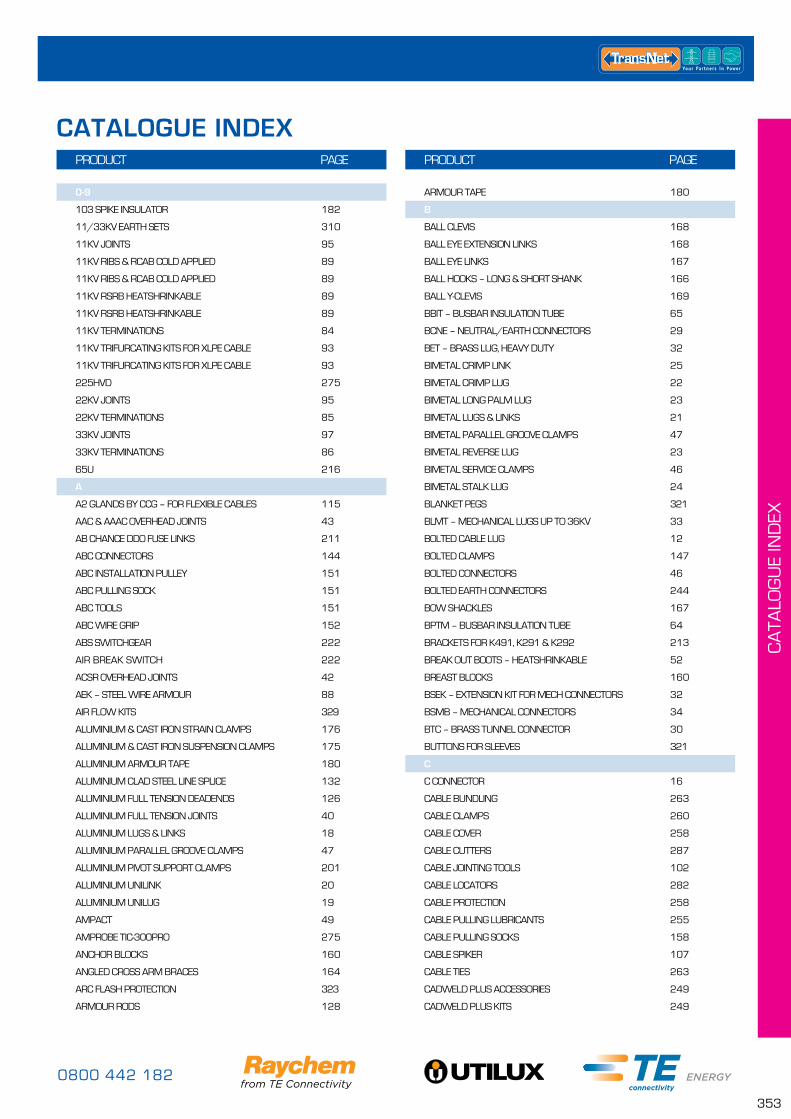
0800 442 182
353
CA
TALO
GU
E IN
DEX
0-9
103 SPIKE INSULATOR 182
11/33KV EARTH SETS 310
11KV JOINTS 95
11KV RIBS & RCAB COLD APPLIED 89
11KV RIBS & RCAB COLD APPLIED 89
11KV RSRB HEATSHRINKABLE 89
11KV RSRB HEATSHRINKABLE 89
11KV TERMINATIONS 84
11KV TRIFURCATING KITS FOR XLPE CABLE 93
11KV TRIFURCATING KITS FOR XLPE CABLE 93
225HVD 275
22KV JOINTS 95
22KV TERMINATIONS 85
33KV JOINTS 97
33KV TERMINATIONS 86
65U 216
A
A2 GLANDS BY CCG – FOR FLEXIBLE CABLES 115
AAC & AAAC OVERHEAD JOINTS 43
AB CHANCE DDO FUSE LINKS 211
ABC CONNECTORS 144
ABC INSTALLATION PULLEY 151
ABC PULLING SOCK 151
ABC TOOLS 151
ABC WIRE GRIP 152
ABS SWITCHGEAR 222
AIR BREAK SWITCH 222
ACSR OVERHEAD JOINTS 42
AEK – STEEL WIRE ARMOUR 88
AIR FLOW KITS 329
ALUMINIUM & CAST IRON STRAIN CLAMPS 176
ALUMINIUM & CAST IRON SUSPENSION CLAMPS 175
ALUMINIUM ARMOUR TAPE 180
ALUMINIUM CLAD STEEL LINE SPLICE 132
ALUMINIUM FULL TENSION DEADENDS 126
ALUMINIUM FULL TENSION JOINTS 40
ALUMINIUM LUGS & LINKS 18
ALUMINIUM PARALLEL GROOVE CLAMPS 47
ALUMINIUM PIVOT SUPPORT CLAMPS 201
ALUMINIUM UNILINK 20
ALUMINIUM UNILUG 19
AMPACT 49
AMPROBE TIC-300PRO 275
ANCHOR BLOCKS 160
ANGLED CROSS ARM BRACES 164
ARC FLASH PROTECTION 323
ARMOUR RODS 128
ARMOUR TAPE 180
B
BALL CLEVIS 168
BALL EYE EXTENSION LINKS 168
BALL EYE LINKS 167
BALL HOOKS – LONG & SHORT SHANK 166
BALL Y-CLEVIS 169
BBIT – BUSBAR INSULATION TUBE 65
BCNE – NEUTRAL/EARTH CONNECTORS 29
BET – BRASS LUG, HEAVY DUTY 32
BIMETAL CRIMP LINK 25
BIMETAL CRIMP LUG 22
BIMETAL LONG PALM LUG 23
BIMETAL LUGS & LINKS 21
BIMETAL PARALLEL GROOVE CLAMPS 47
BIMETAL REVERSE LUG 23
BIMETAL SERVICE CLAMPS 46
BIMETAL STALK LUG 24
BLANKET PEGS 321
BLMT – MECHANICAL LUGS UP TO 36KV 33
BOLTED CABLE LUG 12
BOLTED CLAMPS 147
BOLTED CONNECTORS 46
BOLTED EARTH CONNECTORS 244
BOW SHACKLES 167
BPTM – BUSBAR INSULATION TUBE 64
BRACKETS FOR K491, K291 & K292 213
BREAK OUT BOOTS – HEATSHRINKABLE 52
BREAST BLOCKS 160
BSEK – EXTENSION KIT FOR MECH CONNECTORS 32
BSMB – MECHANICAL CONNECTORS 34
BTC – BRASS TUNNEL CONNECTOR 30
BUTTONS FOR SLEEVES 321
C
C CONNECTOR 16
CABLE BUNDLING 263
CABLE CLAMPS 260
CABLE COVER 258
CABLE CUTTERS 287
CABLE JOINTING TOOLS 102
CABLE LOCATORS 282
CABLE PROTECTION 258
CABLE PULLING LUBRICANTS 255
CABLE PULLING SOCKS 158
CABLE SPIKER 107
CABLE TIES 263
CADWELD PLUS ACCESSORIES 249
CADWELD PLUS KITS 249
PRODUCT PAGE PRODUCT PAGE
CATALOGUE INDEX
www.transnet.co.nz
354
CA
TALO
GU
E IN
DEX
PRODUCT PAGE PRODUCT PAGE
CADWELD PLUS MOLDS 247
CADWELD PLUS ONE SHOT 246
CADWELD PLUS RENTAL KIT INCLUDING MOLD 251
CADWELD PLUS WELD METALS 246
CENTRAL TAG FUSE LINKS 206
CFTS – HEATSHRINK GLANDS 63
CHAIN LINKS 172
CHAIN TENSIONERS 304
CLAMP METERS 270
CLAMPS – JUMPER 308
CLASS 0 GLOVES 317
CLASS 00 GLOVES 317
CLASS 00-0 LEATHER OVERGLOVES 319
CLASS 1 – BOW DAH ARRESTORS 219
CLASS 1 – EVA HDA-MA ARRESTORS 219
CLASS 1 GLOVES 317
CLASS 1-4 LEATHER OVERGLOVES 319
CLASS 2 – STATION CLASS ARRESTORS 220
CLASS 2 GLOVES 318
CLASS 2 SLEEVES 320
CLASS 3 GLOVES 318
CLASS 4 GLOVES 318
CLASS 4 SLEEVES 320
CLEANING LUBRICANTS 256
CLEANING SOLVENT - 1LTR BOTTLE 256
CLEANING SOLVENT WIPES 256
CLEANING, REPAIR & MAINTENANCE 299
CLEVIS THIMBLES 140
CLEVIS TONGUES 171
COMPRESSION DEADENDS 38
CONDUCTIVE SUIT & ACCESSORIES 336
CONNECTOR HOLDING TOOLS 36/287
CONTACT VOLTAGE DETECTORS 274
CONTINUITY TESTERS 276
COOPER BUSSMANN OIL FUSE LINKS 12KV 210
COPPER CRIMP LINK 13
COPPER CRIMP LINK SOLID BARRIER 14
COPPER CRIMP LUG 5
COPPER FLARED LUG (BELLMOUTH) 7
COPPER LUGS & LINKS 4
COPPER PARALLEL GROOVE CLAMPS 47
COPPER REDUCING LINK 15
COPPER STALK LUG 17
CORDLESS IMPACT WRENCH 36/286
COTTON GLOVE LINERS 319
CRC 257
CRIMP TOOL DIES 291
CRIMP TOOLS 289
CRITCHLEY K65 MARKERS 265
CROSS ARM BRACES 163
CROSS ARM GAIN BLOCKS 163
CROSS ARM SPREADER BOLTS 172
CROSS ARM STRINGING ROLLERS 304
CRSM 60
CRSM-CT 77
CRSM-CT-M 77
CRUCIFIX BRACKETS 84
CSCOPE 282
CW GLANDS – FOR SWA & ALI ARMOURED CABLES 116
D
DCPT 61
DDO FUSE LINKS 211
DDO FUSE UNITS 218
DEADENDS 124
DECOILERS 305
DENSO TAPE 254
DISTRIBUTION TIES 138
DO NOT CLIMB TAGS 267
DONUT BLOCKS 160
DOUBLE ARMING BOLTS 172
DOUBLE CROSS ARM SPREADER BOLTS 172
DOUBLE SUSPENSION YOKE BRACKET 149
DUCT SEALING PLUGS 120
DUCT SEALING SYSTEMS 120
DWP/ATUM – ES1000/ES2000 56
E
EAKT – METAL CABLE GLANDS 119
EAKT – PAPER LEAD ARMOUR 88
EARTH BAR 88
EARTH BRAID 80
EARTH ROD COUPLERS 242
EARTH ROD DRIVING TIPS 242
EARTH ROD DRIVING TOOL 243
EARTH ROD INSPECTION BOXES 243
EARTH RODS 243
EARTH TESTING 277
EARTHING KITS 88
ECOBLOCK – HEEL/DONUT/BREAST BLOCKS 160
ECOPILLAR – SERVICE PILLARS 234
ELECTRICAL JOINTING COMPOUND 20
ELLIPTICAL JOINTS 26
END CAPS – COLD APPLIED PUSH ON 53
END CAPS – HEATSHRINKABLE 52/53
EP0 234
EP1 235
EP2 235
EP2S 236
EP3 236
EP3.5 237
EP4 237
0800 442 182
355
CA
TALO
GU
E IN
DEX
EP6 238
EPKJ – LV JOINTS FOR CONTROL CABLES 78
EPKJ – LV JOINTS PAPER INSULATED CABLES 78
EPKJ – LV TRANSITION JOINTS (ARMOURED CABLES) 78
ESJ – LV JOINTS 77
ESJ-R – LV RESIN JOINTS WITH MECH. CONN 73
EVA INSULATORS 200
EVERLAST 1" POLE MARKERS 266
EVERLAST PHASE MARKERS 267
EXOTHERMIC CONNECTIONS 246
EYE BOLTS 165
EYE NUTS 150
EZI SHRINK 54
F
FACE SHIELDS 323
FAULT PASSAGE INDICATORS 221
FCSM 62
FIBRE OPTIC CABLE SOLVENT WIPES 256
FILOSEAL+ – DUCT SEALING SYSTEM 122
FLUKE-289 273
FLUKE-376 270
FLUKE-381 270
FLUKE-T130 276
FLUKE-T150 276
FULL TENSION OVERHEAD JOINTS 40
FUSE & PANEL KITS 238
FUSE LINKS 204
FUSE PULLING TOOLS 216
G
G&W SWITCHGEAR 223
GALVANISED SCREW ANCHORS 161
GALVANISED STAY WIRE 161
GEL FILLED PRODUCTS 68
GELCAP-SL 70
GELPORT 68
GELWRAP 70
GENERAL JOINTING TOOLS 102
GHFC GEL ENCLOSURES 69
GLAND ACCESSORIES 117
GLANDS 114
GLOVE POWDER 322
GLOVE SIZING GUIDE 316
GLOVES 317
GRIP ALL HOTSTICKS 298
GURO RESIN JOINT KITS 72
GUROFLEX RESIN 72
GUROSIL – GEL FILLED JUNCTION BOX 71
GUY FITTINGS 134
GUY GUARD 260
GUY THIMBLES 162
H
HAND CABLE CUTTERS 287
HAND CLEANING WIPES 256
HAND OPERATED CRIMP TOOLS 289
HARNESS & STRAPS FOR SLEEVES 321
HEATSHRINK GLANDS 63/119
HEATSHRINK REPAIR SLEEVE 60
HEATSHRINK TAPE 63
HEATSHRINK TUBING 54
HEATSHRINKABLE END CAP 146
HEAVY DUTY COPPER LUGS 10
HEAVY WALL HEATSHRINK 59
HEEL BLOCKS 160
HEL – BRASS CONNECTOR UP TO 1KV 29
HEL – HELSTERN CONNECTORS UP TO 1KV 29
HELICAL BUNDLE RESTRAINTS 155
HELICAL SUPPORT & SUSPENSION UNITS 135
HOODS 328
HOOK BOLTS 149/156
HOOK BRACKETS 150
HOOK NUTS 150
HOTSTICK REPAIR KITS 299
HOTSTICK TOOL ACCESSORIES 300
HOUSE CONNECTION 146
HOUSE HOOK 147
HV ABC RESTRAINTS 155
HV ABC ROLLER 157
HV ABC STRINGING EQUIPMENT 157
HV ABC SUSPENSION SET UP 156
HV INSULATION TESTERS 279
HVBT – HIGH VOLTAGE BUSBAR TAPE 64
HVIS – HIGH VOLTAGE INSULATION SHEETS 65
HY-DEE BRAIT ROPE 302
HYDRAULIC CABLE CUTTERS 288
HYDRAULIC CRIMP TOOLS 290
I
IDENTIFICATION & LABELLING 265
IET15M 278
INSTALLATION PULLEY 157
INSULATED IPC RATCHET SPANNER 152
INSULATING MATS & PIPES 320
INSULATION BUSHING BOOTS 89
INSULATION PIERCING CONNECTORS 28/145
INSULATION TAPE 254
INSULATORS 182
IPC'S – INSULATION PIERCING CONNECTORS 28/145
J
J TYPE FUSE LINKS 207
JOINTING COMPOUND 20
JUMPERS 310
PRODUCT PAGE PRODUCT PAGE
www.transnet.co.nz
356
CA
TALO
GU
E IN
DEX
K
K199 216
K221 216
K223 212
K291 & K292 213
K491 213
KNIVES 102/284
KRONE KGH160 214
KRONE KGH250 214
KRONE KGH400 215
L
LEATHER OVERGLOVES & COTTON LINERS 319
LED LIGHT STANDS 306
LESK – LV LIVE END SEAL KITS 79
LIGHT STANDS 306
LINE GUARDS 130
LINE HARDWARE 166
LIVE LINE ROPE 302
LINE SPLICES 131
LINK BOX 81/239
LINK BOX & PILLAR KITS 81/239
LINK PILLAR 81/239
LIQUID RUBBER CLEANER 299/322
LIVE END SEALS 101
LIVE LINE CLAMPS 48
LIVE LINE CLEANERS 299
LIVE LINE SUIT 336
LJSM – LV JOINT 76
LJTM – LV INLINE TRANSITION JOINTS 78
LOAD LIFTING TOOLS & ACCESSORIES 295
LONG PALM LONG BARREL COPPER CRIMP LUGS 11
LUG SOLDER TYPE 10
LUGS & LINKS – COMPRESSION 3
LV ABC BOLTED CLAMPS 147
LV ABC SEPARATING WEDGES 151
LV EARTH SETS 311
LV HEATSHRINK MULTIPACKS 56
LV ISOLATING LINK - FUSED/UNFUSED 215
LV JUMPERS 310
LV LINK BOX & PILLAR KITS 81/239
LV MATS 320
LV MECHANICAL LUGS & LINKS 29
LV OVERHEAD FUSE SWITCHES 212
LV SPREADER ROD & CONDUCTOR CLIP 179
LV UNDERGROUND FUSE SWITCHES 216
LVBT – LOW VOLTAGE BUSBAR TAPE 63
LVIT 62
LVJM - LV JOINT 76
LVK & TJ – LV JOINTS FOR TPS 77
LVTE – LV END OF RUN JOINTS 79
LVTM – LV TERMINATION KITS, WITH MECH CONN 79
M
M249A 272
M611E 277
MAINS ENTRY BOX 146
MAINTENANCE TENSION LINKS 174
MARCM58 272
MARCM67 271
MARPSI4000 281
MARTL78 278
MD9040 273
MD9240 271
MD9270 271
MEASURING TRIANGULAR TELESCOPIC HOTSTICKS 297
MECHANICAL CONNECTOR TOOLS 36/286
MECHANICAL CONNECTORS 27
MECHANICAL WEDGE CONNECTORS 245
MEDIUM VOLTAGE BUSBAR INSULATION 64
MEDIUM WALL HEATSHRINK 58
METRAVOLT12D+L 276
MI2126 277
MI2X92 SERIES 279
MI3200 280
MI3201 279
MI3242 280
MI3250 280
MI3252 280
MI3309 278
MICROOHM TESTERS 280
MID SPAN COMPRESSION CONNECTORS 40
MINI WEDGE CONNECTION SYSTEM 48
MINI WEDGE GEL ENCLOSURES 70
MOLD RENTAL KIT 251
MOULDED ACCESSORIES 52
MULTIMETERS 272
MV JUMPERS 311
MV MATS 320
MV MECHANICAL LUGS & LINKS 33
MV OVERHEAD DDO'S (CUT OUTS) 218
MV PIN TYPE INSULATORS 186
MV POST TYPE INSULATORS 188
MV STRAIN INSULATORS 198
MV SWITCHGEAR 222
MWTM 58
N
NARROW PALM CIRCUIT BREAKER LUG 8
NEOPRENE INSERT – CABLE CLAMP 262
NEUTRAL SCREEN STRAIN CLAMP 128
PRODUCT PAGE PRODUCT PAGE
0800 442 182
357
CA
TALO
GU
E IN
DEX
NH DIN TYPE 209
NON TENSION OVERHEAD JOINTS 41
NON-CONTACT VOLTAGE DETECTORS 274
NYLON CABLE GLANDS 114
NYLON CABLE TIES 263
O
OFFSET TAG FUSE LINKS 204
OVERHEAD – FLITE110SA & FLITE116SA 221
OVERHEAD COMPRESSION CONNECTORS 38
P
PERSONAL TOOLS 284
PHASE TESTERS 281
PILC JOINT KITS 99
PILC TERMINATION KITS 87
PILLARS 234
PIT300D KITS – NO BREACH JOINT 231
PIVOT SUPPORT CLAMPS 175/201
PLUG IN TERMINATION 42KV– RPIT 93
PODGERS 284
POLE GUARDS 259
POLE HARDWARE 163
POLE STEPS 164
POLYMER INSULATORS 198
PORCELAIN INSULATORS 182
PORTABLE APPLIANCE TESTERS 278
POST TYPE INSULATORS 188
POWER QUALITY ANALYSERS 279
PRE-INSULATED COMPRESSIOIN – LUGS & LINKS 144
PRO WEAR® – CLOTHING 330
PROTECTIVE RUBBER EQUIPMENT LABELLING CHART 316
PRO-WEAR® KITS 333
PUSH ON END CAP 145
PXE – LV RESIN JOINTS 73
R
RAT STRAP 157
RATCHET CABLE CUTTERS 288
RAYGEL ENCLOSURES & JOINT KITS 68
RDSS – RAYFLATE DUCT SEALING SYSTEM 121
RDSS ACCESSORIES 122
REM OIL 49/257
RESIN – RAPID 4300 75
RESIN JOINTS 72
RICKY CHAIN TENSIONER 304
RICS INSULATED ELBOWS 90
RISING MAINS CONNECTORS 28
RNF100 55
ROLL ON JOINT SYSTEM 80
ROLL SPRINGS 81
ROPE BLOCKS 297
RPITS 93
RSSS FOR TYPE A BUSHINGS 90
RSTI INSULATED SCREENED ELBOWS 91
RSTI-CC PIGGYBACK COUPLING SYSTEM 91
RSTI-SA SURGE ARRESTOR ELBOWS 92
RUBBER GOODS ACCESSORIES 321
RUBBER INSULATING GLOVES 317
RUBBER INSULATING SLEEVES 320
RUBBER LABELLING & SIZING 316
RVS – RAYVOLVE ROLL ON JOINTING SLEEVES 80
S
SAGLINKS 174
SCREENED ELBOW TERMINATION KITS 90
SEALED COPPER CRIMP LUG 9
SEK – COPPER TAPE SCREEN 88
SELF AMALGAMATING TAPE 254
SEPARATING WEDGES 151
SERVICE CLAMPS - LV 147
SHACKLE STRAPS & "U" SHACKLE STRAPS 173/184
SHEARBOLT CONNECTORS 27
SHEAR-LOK 245
SIDE TIES 139
SINGLE CONDUCTOR CABLE CLAMPS 261
SIZING GUIDE & MATERIAL WEIGHTS 330
SOCKET CLEVIS 169
SOCKET CLEVIS EXTENSION LINKS 170
SOCKET THIMBLES 141
SOCKET TONGUE 170
SPECIALIST STRIPPING TOOLS 105
SPIKE INSULATOR 182
SPIRAL VIBRATION DAMPERS 139/176
SPLIT BOLTS 46
STAGGERED TAG 204
STAINLESS STEEL BAND STRAP & BUCKLES 264
STAINLESS STEEL CABLE TIES 264
STAY HARDWARE 160
STAY RODS AND BOWS 162
STEEL GUY GRIPS 134
STEEL GUY LOCKS 134
STOCKBRIDGE DAMPERS 177
STORAGE BAGS 299/322
STRAIN INSULATORS 198
STRAP HOISTS 296
STRINGING ROLLERS 303
SUPPORT UNITS - HELICAL 135
SURGE ARRESTORS 218
SURGE ARRESTOR EYEBOLT CONNECTOR 218
SUSPENSION BRACKET 156
SUSPENSION CLAMPS - HELICAL 137
PRODUCT PAGE PRODUCT PAGE
www.transnet.co.nz
358
CA
TALO
GU
E IN
DEX
SUSPENSION CLAMPS - HV ABC 156
SUSPENSION CLAMPS - LV ABC 148
SUSPENSION UNITS - HELICAL 135
SWIVELS - HV ABC 158
SWIVELS - LV ABC 152
T
TAPE 254
TAPPAT 2 WAY LINK PILLAR 80/239
TAPPAT 3 WAY LINK PILLAR 81/240
TAPPAT LINK BOX 80/239
TBJ – LV RESIN BRANCH JOINTS 74
TECHLUBE 255
TECHLUBE HEAVY DUTY 255
TECHLUBE HEAVY DUTY PRE-LUBE 255
TECHLUBE PHD 255
TELECOM CRIMP SLEEVES 44
TELECOM CRIMPS – FULL TENSION COPPER CRIMPS 44
TEMPORARY EARTH SETS 311
TEMPORARY LIGHT STANDS 306
TENSION CLAMPS 148
TENSION METERS 296
TFER 61
THIN WALL HEATSHRINK 54
TIC-300PRO 275
TIE WIRE 180
TIGER TAILS 321
TN275NZHP 275
TN275NZHP-HANDLE 275
TN855 281
TN895PR 281
TNLVD-15 274
TNLVD-17 274
TNNHP100 FUSE CARRIER 213
TOMKAT2 282
TONGUE HOOKS 166
TOOL ATTACHMENTS FOR HOTSTICKS 300
TOOL BAGS 284
TOOLS FOR TELECOM CRIMPS 44
TRANSDELTA4 278
TRANSITION JOINT KITS 100
TREFOIL CONDUCTOR CLAMPS 262
TRIANGULAR TELESCOPIC HOTSTICKS 297
TRIFURCATING KITS 93
TSJ – LV RESIN JOINTS 74
TUDS ACCESSORIES 232
TUDS KITS – WITH BREACH JOINT 231
TUDS PIT LIDS 230
TUDS PITS 230
TWISTED CLEVIS TONGUES 172
PRODUCT PAGE PRODUCT PAGE
TWISTED EYE TONGUES 171
U
UBR – UNIVERSAL BRANCH CONNECTOR 30
UBRXX-SBD – UNIVERSAL BRANCH, DOUBLE SERVICE 31
UKR 90 CABLE CLAMPS 260
UNDERGROUND – FLAIR213 & FLAIR279 221
UNILINK ALUMINIUM 20
UNILUG FOR ALUMINIUM CABLES 19
UNIVERSAL CABLE CLAMPS – UKR 90 260
UNIVERSAL HOTSTICKS 298
UNIVERSAL STRINGING ROLLERS 303
USBXX-D – UNIVERSAL BRANCH, DOUBLE SERVICE 31
UST – UNIVERSAL STRAIGHT CONNECTOR 30
USTXX-SBD – UNIVERSAL STRAIGHT, DOUBLE SERVICE 32
V
VESTS & RAIN JACKETS 336
VIBRATION DAMPERS 139/177
W
WARNING STRIP 259
WCSM 59
WEAK LINKS 150
WEDGE PRESSURE CONNECTORS 48
WIRE GRIPS 295
WIRE ROPE GRIPS 161
WRENCH-LOK 245
WRICONS 248
X
XLPE JOINT KITS 94
XLPE LV INLINE HEATSHRINK JOINTS 76
XLPE TERMINATION KITS 84
Y
Y CLEVIS TONGUE 169
YOKE BAR 157
YOKE PLATES 174
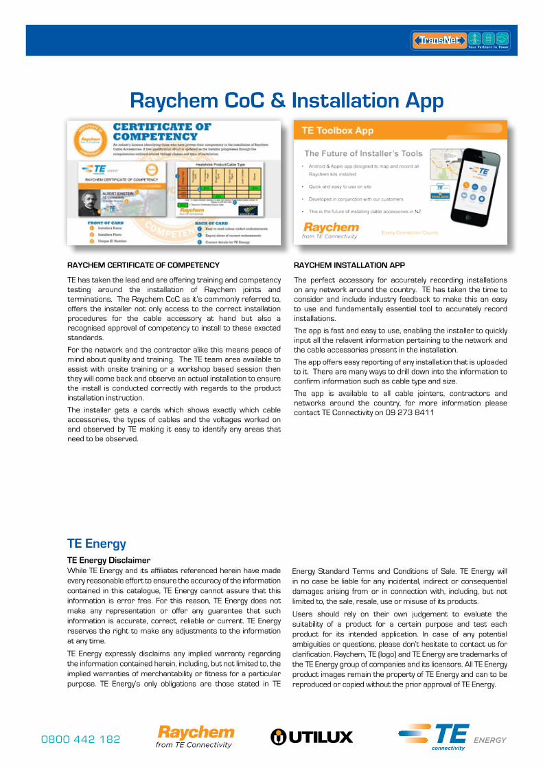
Raychem CoC & Installation App
RAYCHEM CERTIFICATE OF COMPETENCY
TE has taken the lead and are offering training and competency testing around the installation of Raychem joints and terminations. The Raychem CoC as it’s commonly referred to, offers the installer not only access to the correct installation procedures for the cable accessory at hand but also a recognised approval of competency to install to these exacted standards.
For the network and the contractor alike this means peace of mind about quality and training. The TE team area available to assist with onsite training or a workshop based session then they will come back and observe an actual installation to ensure the install is conducted correctly with regards to the product installation instruction.
The installer gets a cards which shows exactly which cable accessories, the types of cables and the voltages worked on and observed by TE making it easy to identify any areas that need to be observed.
RAYCHEM INSTALLATION APP
The perfect accessory for accurately recording installations on any network around the country. TE has taken the time to consider and include industry feedback to make this an easy to use and fundamentally essential tool to accurately record installations.
The app is fast and easy to use, enabling the installer to quickly input all the relavent information pertaining to the network and the cable accessories present in the installation.
The app offers easy reporting of any installation that is uploaded to it. There are many ways to drill down into the information to confirm information such as cable type and size.
The app is available to all cable jointers, contractors and networks around the country, for more information please contact TE Connectivity on 09 273 8411
TE Energy DisclaimerWhile TE Energy and its affiliates referenced herein have made every reasonable effort to ensure the accuracy of the information contained in this catalogue, TE Energy cannot assure that this information is error free. For this reason, TE Energy does not make any representation or offer any guarantee that such information is accurate, correct, reliable or current. TE Energy reserves the right to make any adjustments to the information at any time.
TE Energy expressly disclaims any implied warranty regarding the information contained herein, including, but not limited to, the implied warranties of merchantability or fitness for a particular purpose. TE Energy’s only obligations are those stated in TE
Energy Standard Terms and Conditions of Sale. TE Energy will in no case be liable for any incidental, indirect or consequential damages arising from or in connection with, including, but not limited to, the sale, resale, use or misuse of its products.
Users should rely on their own judgement to evaluate the suitability of a product for a certain purpose and test each product for its intended application. In case of any potential ambiguities or questions, please don’t hesitate to contact us for clarification. Raychem, TE (logo) and TE Energy are trademarks of the TE Energy group of companies and its licensors. All TE Energy product images remain the property of TE Energy and can to be reproduced or copied without the prior approval of TE Energy.
TE Energy
0800 442 182

0800 442 182 +64 9 274 [email protected] #TNUTILCAT 05/14
Wellington18 Sydney StreetPetoneWellingtonNEW ZEALAND Ph0800 442 182Fax 0800 442 183PO Box 39 383 Howick, [email protected]
NEW ZEALAND
TransNet New Zealand Ltd Auckland20 Neilpark DriveEast TamakiAucklandNEW ZEALAND Ph0800 442 182 Fax 0800 442 183PO Box 39 383 Howick, [email protected]
NEW ZEALAND
TransNet Equipment Pty Ltd Perth Unit 20, 8 Hurley StreetCanning Vale WA 6155PerthAUSTRALIA Ph+61 8 9256 3417Fax +61 8 9256 3917PO Box 1439Canning Vale DC WA [email protected] AUSTRALIA
TransNet Tonga TongaSmall IndustriesMa’ufangaTONGA Ph+67 627 939Fax +67 627 976 PO Box 2932Nukualofa [email protected] TONGA
Raychem technical team on site during the Christchurch earthquake recovery effort. – Repairing 66kV cable damage.