transport and binding of insulin-like growth factors to
TRANSCRIPT
Transport and Binding of Insulin-Like Growth Factors to
Articular Cartilage
by
N6ra Szasz
Submitted to the Department of Electrical Engineering and Computer Sciencein partial fulfillment of the requirements for the degrees of
Bachelor of Science
and
Master of Engineering
at the
MASSACHUSETTS INSTITUTE OF TECHNOLOGY
JLJay 1999
@ N6ra Szaisz, MCMXCIX. All rights reserved.
The author hereby grants to MIT permission to reproduce and distribute publiclypaper and electronic copies of this thesis document in whole or in part.
Author ............
Certified by.................
Accepted by .............
. . . . . . . . . . . . . . . . . . . .. . . . . . . . . . . . . . . . . . . . . . . . . . .Department of Electrical Engineering and Computer Science
May 21, 1999
. . -.. . .. .. . . . . . . . . . . . . . . . . . . . . . . .. . .
Alan J. Grodzinskyofsor of Electric'al,'* v chanical, and Bioengineering
Thesis Supervisor
.................. ...............L' . . . . . . . . . . .
Arthur C. SmithStudentsChairman, Department Committee
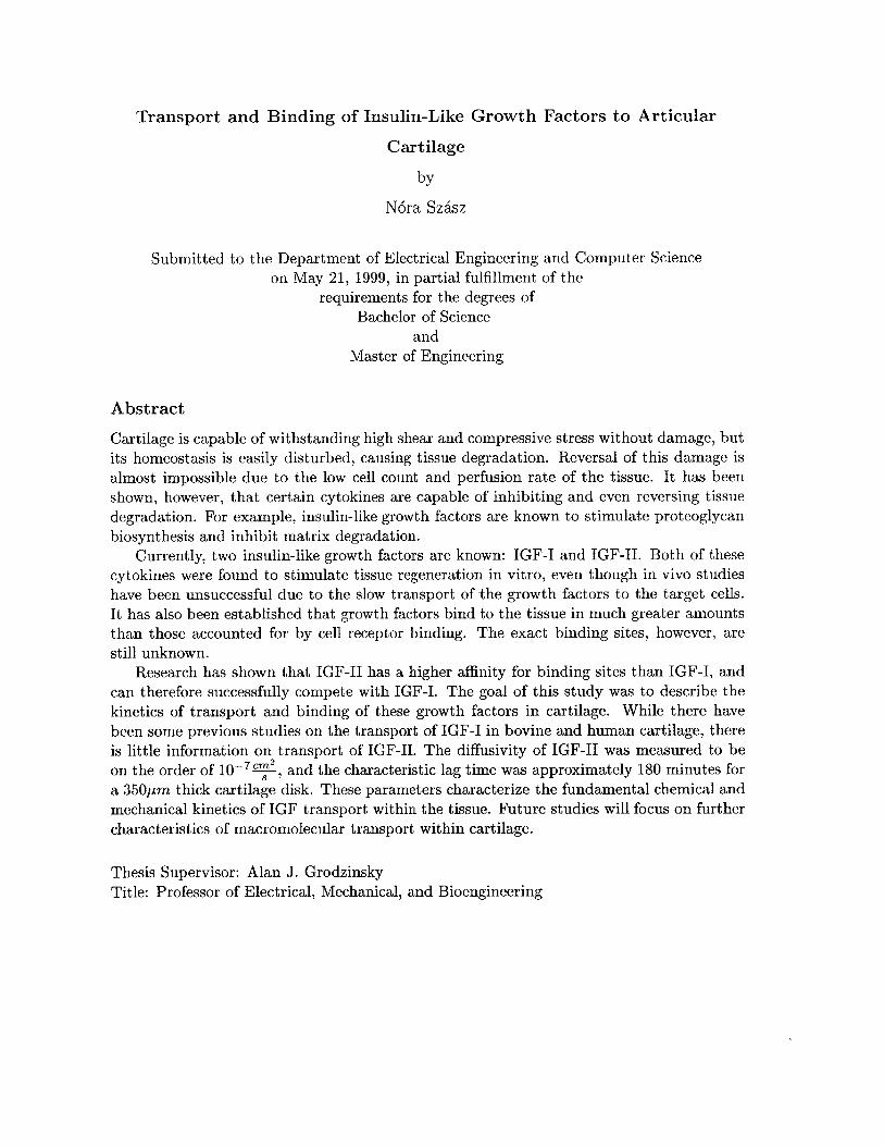
Transport and Binding of Insulin-Like Growth Factors to Articular
Cartilage
by
N6ra Szisz
Submitted to the Department of Electrical Engineering and Computer Scienceon May 21, 1999, in partial fulfillment of the
requirements for the degrees ofBachelor of Science
andMaster of Engineering
Abstract
Cartilage is capable of withstanding high shear and compressive stress without damage, butits homeostasis is easily disturbed, causing tissue degradation. Reversal of this damage isalmost impossible due to the low cell count and perfusion rate of the tissue. It has beenshown, however, that certain cytokines are capable of inhibiting and even reversing tissuedegradation. For example, insulin-like growth factors are known to stimulate proteoglycanbiosynthesis and inhibit matrix degradation.
Currently, two insulin-like growth factors are known: IGF-I and IGF-II. Both of thesecytokines were found to stimulate tissue regeneration in vitro, even though in vivo studieshave been unsuccessful due to the slow transport of the growth factors to the target cells.It has also been established that growth factors bind to the tissue in much greater amountsthan those accounted for by cell receptor binding. The exact binding sites, however, arestill unknown.
Research has shown that IGF-II has a higher affinity for binding sites than IGF-I, andcan therefore successfully compete with IGF-I. The goal of this study was to describe thekinetics of transport and binding of these growth factors in cartilage. While there havebeen some previous studies on the transport of IGF-I in bovine and human cartilage, thereis little information on transport of IGF-II. The diffusivity of IGF-II was measured to beon the order of 1O , and the characteristic lag time was approximately 180 minutes fora 350pm thick cartilage disk. These parameters characterize the fundamental chemical andmechanical kinetics of IGF transport within the tissue. Future studies will focus on furthercharacteristics of macromolecular transport within cartilage.
Thesis Supervisor: Alan J. GrodzinskyTitle: Professor of Electrical, Mechanical, and Bioengineering
Acknowledgments
This thesis would not have been possible without the help of
" Prof. Alan Grodzinsky, my supervisor, who led me into a new field, and provided
advice and enthusiasm throughout my work,
* Eliot Frank, who helped me fix what was broken, and beat the experiments into
submission,
" Teresa Morales, who has helped me force the growth factors do their duty,
* Linda Bragman, who helped me fight the eternal bureaucracy,
" The Continuum Electromechanics Group, who made the lab a fun place to be,
" MIT, which believed I could succeed four years ago, and gave me that trust for the
next four (five? six?) years,
" Boris Zbarsky, who was at the receiving end of all my frustrations during these past
few weeks,
" Prof. Jane Dunphy, who taught me how to write without making my readers cringe,
" Several of my high school teachers - Fl6rik Gy6rgy, T6th Attila, and Czir6k Ede -
who have given me my love for science, and
" My parents, who have given me all that I have.
Thank you.
This research was sponsored in part by NIH Grant AR33236.
Contents
1 Introduction 101.1 Background . . . . . . . . . . . . . . . . . . . . . . . . . . . . . . . . . . .. 10
1.2 O bjective . . . . . . . . . . . . . . . . . . . . . . . . . . . . . . . . . . . . . 101.3 Overview . . . . . . . . . . . . . . . . . . . . . . . . . . . . . . . . . . . .. 11
2 Articular Cartilage 12
2.1 Articular Cartilage Anatomy . . . . . . . . . . . . . . . . . . . . . . . . . . 12
2.1.1 Chondrocytes and the Chondron . . . . . . . . . . . . . . . . . . . . 13
2.1.2 Extracellular Matrix . . . . . . . . . . . . . . . . . . . . . . . . . . . 14
2.1.3 Collagen . . . . . . . . . . . . . . . . . . . . . . . . . . . . . . . . .. 142.1.4 Proteoglycans . . . . . . . . . . . . . . . . . . . . . . . . . . . . . . . 14
2.2 Regulatory solutes . . . . . . . . . . . . . . . . . . . . . . . . . . . . . . . . 16
2.2.1 Insulin-like Growth Factors . . . . . . . . . . . . . . . . . . . . . . . 17
3 Transport Kinetics 19
3.1 D iffusion . . . . . . . . . . . . . . . . . . . . . . . . . . . . . . . . . . . . .. 193.1.1 Fick's Laws . . . . . . . . . . . . . . . . . . . . . . . . . . . . . . . . 19
3.1.2 Stokes-Einstein Model . . . . . . . . . . . . . . . . . . . . . . . . . . 21
3.1.3 Non-Steady-State Kinetics . . . . . . . . . . . . . . . . . . . . . . . . 22
3.1.4 The Effect of Binding . . . . . . . . . . . . . . . . . . . . . . . . . . 233.2 Migration . . . . . . . . . . . . . . . . . . . . . . . . . . . . . . . . . . . . . 25
3.2.1 Ohm's Law . . . . . . . . . . . . . . . . . . . . . . . . . . . . . . . . 253.3 Convection . . . . . . . . . . . . . . . . . . . . . . . . . . . . . . . . . . . . 26
3.3.1 Darcy's Law . . . . . . . . . . . . . . . . . . . . . . . . . . . . . . . 26
3.4 Coupled Transport Equations . . . . . . . . . . . . . . . . . . . . . . . . . . 26
3.4.1 The Transport Equations . . . . . . . . . . . . . . . . . . . . . . . . 27
4 Previous Work 29
4.1 Stimulation of Biosynthesis by Increased Perfusion Rate . . . . . . . . . . . 29
4.2 IGF-I and IGF-II Competition for Binding Sites . . . . . . . . . . . . . . . 294.3 IGF-I Transport Kinetic Studies . . . . . . . . . . . . . . . . . . . . . . . . 33
4.4 IGF-II Transport Kinetic Studies . . . . . . . . . . . . . . . . . . . . . . . . 34
5 Experimental Controls 36
5.1 Testing Binding to the Radiomatic . . . . . . . . . . . . . . . . . . . . . . . 365.2 Resistance of the Baths . . . . . . . . . . . . . . . . . . . . . . . . . . . . . 36
4
6 Free Iodide Transport 386.1 Methods . . . . . . . . . . . . . . . . . . . . . . . . . . . . . . . . . . . . . . 386.2 Results . . . . . . . . . . . . . . . . . . . . . . . . . . . . . . . . . . . . . . . 396.3 Discussion . . . . . . . . . . . . . . . . . . . . . . . . . . . . . . . . . . . . . 41
7 IGF Transport Through Cartilage 45
7.1 Experiment 1. . . . . . . . . . . . . . . . . . . . . . . . . . . . . . . . . . . . 45
7.1.1 Methods . . . . . . . . . . . . . . . . . . . . . . . . . . . . . . . . . . 45
7.1.2 Results . . . . . . . . . . . . . . . . . . . . . . . . . . . . . . . . .. 47
7.1.3 Discussion. . . . . . . . . . . . . . . . . . . . . . . . . . . . . . . . . 487.2 Experiment 2. . . . . . . . . . . . . . . . . . . . . . . . . . . . . . . . . . . . 52
7.2.1 Method . . . . . . . . . . . . . . . . . . . . . . . . . . . . . . . . . . 537.2.2 Results . . . . . . . . . . . . . . . . . . . . . . . . . . . . . . . . . . 53
7.2.3 Discussion. . . . . . . . . . . . . . . . . . . . . . . . . . . . . . . . . 57
7.3 Experiment 3. . . . . . . . . . . . . . . . . . . . . . . . . . . . . . . . . . . . 58
7.3.1 Methods . . . . . . . . . . . . . . . . . . . . . . . . . . . . . . . . . . 587.3.2 Results and Discussion. . . . . . . . . . . . . . . . . . . . . . . . . . 58
8 Conclusions 668.1 Summary . . . . . . .. . . .. .. . . . . . . . . . . . . . .. . . . . . . . . 66
8.2 Future Work . . . . . . . . . . .. . . . . . . . . . . . . . . . . . . . . . . . 66
5
List of Figures
2-1 Schematic diagram of a typical aggrecan. (Figure has been taken from Heine-
gard et al.) . . . . . . . . . . . . . . . . . . . . . . . . . . . . . . . . . . . . 15
2-2 Stereo view of IGF-I and IGF-II. . . . . . . . . . . . . . . . . . . . . . . . . 18
3-1 Definition of variables involved in deriving relations for steady-state diffusion
across a membrane and infinitely large baths on both sides. . . . . . . . . . 20
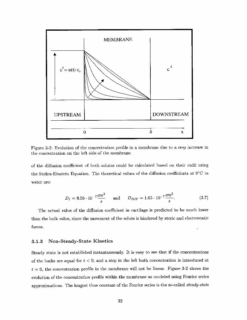
3-2 Evolution of the concentration profile in a membrane due to a step increase
in the concentration on the left side of the membrane. . . . . . . . . . . . . 22
3-3 The theoretical quantity of solute that has diffused across the membrane by
tim e t. . . . . . . . . . . . . . . . . . . . . . . . . . . . . . . . . . . . . . . . 23
4-1 Bhakta et al.'s equilibration study showing the competition between labeled
and unlabeled IGF-I. . . . . . . . . . . . . . . . . . . . . . . . . . . . . . . . 304-2 Bhakta et al.'s equilibration study showing the competition between unla-
beled IGF-I and labeled IGF-II. . . . . . . . . . . . . . . . . . . . . . . . . . 314-3 Bhakta et al.'s equilibration study showing the competition for binding sites
between labeled and unlabeled IGF-II. . . . . . . . . . . . . . . . . . . . . . 324-4 Garcia et al.'s transport kinetic study showing the downstream radioactivity
of labeled IG F-I. . . . . . . . . . . . . . . . . . . . . . . . . . . . . . . . . . 334-5 Bhakta's IGF-II transport kinetic study showing the downstream count of
labeled IG F-II. . . . . . . . . . . . . . . . . . . . . . . . . . . . . . . . . . . 34
5-1 Effects of BSA and NaCl concentration on binding to the experimental ap-
paratus. . . . . . . . . . . . . . . . . . . . . . . . . . . . . . . . . . . . . . . 37
6-1 Experimental setup for transport measurements. . . . . . . . . . . . . . . . 39
6-2 Downstream radioactivity for 1251- transport experiment across articular car-
tilage during electrophoresis. . . . . . . . . . . . . . . . . . . . . . . . . . . 40
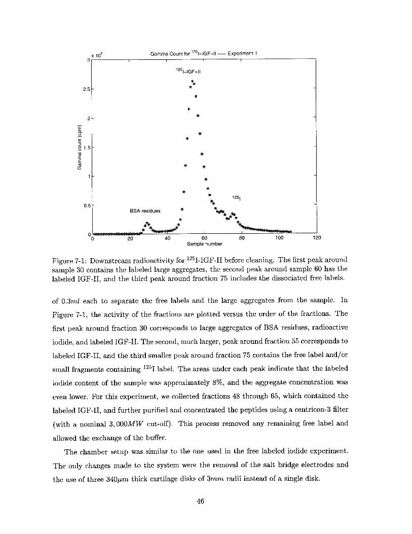
7-1 Downstream radioactivity for 12 5I-IGF-II before cleaning. The first peak
around sample 30 contains the labeled large aggregates, the second peak
around sample 60 has the labeled IGF-II, and the third peak around fraction
75 includes the dissociated free labels. . . . . . . . . . . . . . . . . . . . . . 46
7-2 The plot shows the 125 I-IGF-II downstream radioactivity versus time for
Experiment 1, which describes the transport and binding kinetics of the
growth factor in cartilage. . . . . . . . . . . . . . . . . . . . . . . . . . . . . 47
6
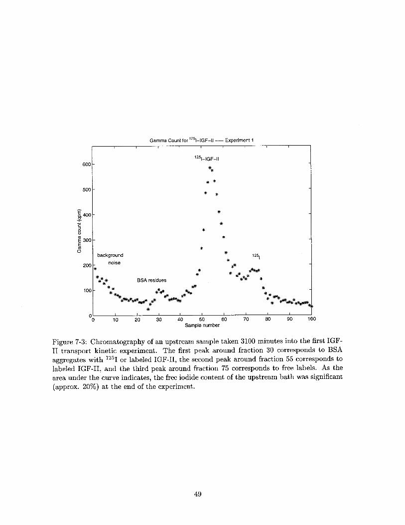
7-3 Chromatography of an upstream sample taken 3100 minutes into the first
IGF-II transport kinetic experiment. The first peak around fraction 30 cor-
responds to BSA aggregates with 125I or labeled IGF-II, the second peak
around fraction 55 corresponds to labeled IGF-I, and the third peak around
fraction 75 corresponds to free labels. As the area under the curve indicates,the free iodide content of the upstream bath was significant (approx. 20%)
at the end of the experiment. . . . . . . . . . . . . . . . . . . . . . . . . .. 49
7-4 The lag time (T) corresponds to the time it takes the growth factor to
diffuse across the cartilage disk. The binding of the growth factor to the
cartilage further increases the lag time . . . . . . . . . . . . . . . . . . . . . 50
7-5 Chromatographic analysis of the 1 25 I-IGF-II before cleaning. The major peak
around fraction 55 is the labeled growth factor, while the two smaller peaks
around fraction 30 and 75 are the large aggregates and the labeled iodide
respectively. The results indicate less than 2% labeled iodide, and even less
large aggregates. . . . . . . . . . . . . . . . . . . . . . . . . . . . . . . . . . 54
7-6 Chromatography of upstream samples at the beginning (*) and end (o) of
the experiments. Notice the low peak of iodide around fraction 75, and the
disappearance of the large aggregates peak around fraction 30. . . . . . . . 55
7-7 The downstream radioactivity of Experiment 2 is plotted versus time. Notice
the lag time after the labeled IGF-II has been added, and the transient
increase in flux after the addition of 15nM unlabeled IGF-II. . . . . . . . . 56
7-8 Chromatographic analysis of labeled IGF-II. It can be seen that the labeled
iodide concentration of the sample is less than 3%, and the large aggregate
content is below 5% . . . . . . . . . . . . . . . . . . . . . . . . . . . . . . . 59
7-9 The downstream radioactivity of Experiment 3 is plotted versus time. . . . 60
7-10 A magnified view of the downstream radioactivity of the first half of Exper-
iment 3. This part of the experiment was the standard binding transport
kinetic study . . . . . . . . ... . ...................... 61
7-11 A magnified view of the downstream radioactivity for the second half of
Experiment 3. This was the pilot study for electrophoretic transport kinetic
studies of IGF-II. . . . . . . . . . . . . . . . . . . . . . . . . . . . . . . . . . 627-12 Chromatographic results of an upstream sample taken after the addition of
the labeled growth factor to the upstream bath in Experiment 3. . . . . . . 64
7-13 Chromatographic results of an upstream sample taken at the end of Experi-
m ent3. . . . ... .. ......... . ... . . . . . . . . . .. . . . . . . . . 65
7
List of Tables
2.1 Type, quantity, and function of the most relevant collagen molecules found
in adult articular cartilage. . . . . . . . . . . . . . . . . . . . . . . . . . . . 15
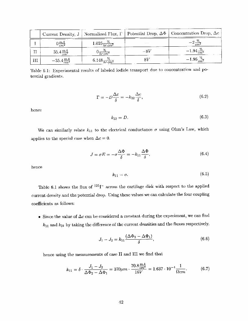
6.1 Experimental results of labeled iodide transport due to concentration and
potential gradients. . . . . . . . . . . . . . . . . . . . . . . . . . . . . . . . . 42
7.1 Steady-state values for the relevant electrophoretic variables during the pilot
study. . . . . . . . . . . . . . . . . . . . . . . . . . . . . . .. . . .. . . . . 63
8
List of Symbols
BSA
CS
ECF
ECM
EDTA
G1, G2, G3
GAG
HA
IGF
IGF-BP
KS
MMP
OA
PBS
PG
PI
PSA
RA
TGF
TIMP
Bovine Serum Albumin
Chondroitin-Sulfate
Extracellular Fluid
Extracellular Matrix
[ethylenedinitrilo]tetraacetic acid
Globular regions of aggrecan's core protein
Glycosaminoglycan
Hyaluronan
Insulin-Like Growth Factor
Insulin-Like Growth Factor Binding Protein
Keratan-Sulfate
Matrix Metalloproteinase
Osteoarthritis
Phosphate Buffered Saline
Proteoglycan
Protease Inhibitor
Penicillin, Streptomycin, and Antibiotics
Retionic Acid
Transforming Growth Factor
Tissue Inhibitor of Metalloproteinases
9
Chapter 1
Introduction
1.1 Background
Articular cartilage is a highly durable weight-bearing material in the synovial joint. Its
durability and resilience to compression are highly dependent on the composition of its
extracellular matrix, which is maintained by a small number of cells. Since cartilage is
avascular and alymphatic, its perfusion rate is low, and, therefore, the production of the
matrix elements is limited by the transport of nutrients, waste, and regulatory solutes within
the tissue.
Normally, nutrients can still be supplied to the cells and toxic waste can be removed
despite the low perfusion rate, but if the tissue is injured, a higher perfusion rate might be
required for tissue regeneration [1, 2]. The anatomy of cartilage suggests that the trans-
port of nutrients, waste, and regulatory solutes should be limited by diffusion. Studies
have shown, however, that a coupling between mechanical, electrical, and chemical forces
can enhance transport and result in a higher tissue perfusion rate, thus increasing tissue
biosynthesis. The stimulation of cartilage tissue by dynamic mechanical loading and the
use of variable electric fields have both been used to achieve increased fluid, and hence
nutrition, flow.
1.2 Objective
The mechanisms that affect the synthesis of cartilage matrix by chondrocytes are not yet
fully understood. It is known that growth factors play an important stimulatory role.
10

Therefore, it is beneficial to describe the rate at which these stimulatory cytokines reach
the cells, and the components to which they bind. The objective of this study has thus been
to characterize the binding and transport kinetic properties of insulin-like growth factors
(IGFs) within bovine articular cartilage, in order to create a quantitative description of
their transport and establish a relationship between IGFs and chondrocyte biosynthesis.
1.3 Overview
The first part of this thesis, Chapters 2-3, establishes the groundwork for the experimental
studies. Chapter 2 describes the unusual biological properties of cartilage and introduce
the structure and function of insulin-like growth factors. Chapter 3 provides the theoretical
background for my calculations and lays down the groundwork for the coupling of electrical,
mechanical, and chemical forces within the tissue.
Chapters 4-7 are the experimental section. Chapter 4 introduces the research that
inspired this thesis, and discusses the results and implications. Chapter 5 describes the
tests that were necessary to validate the experimental system in use, and Chapter 6 presents
a preliminary study describing the transport kinetics of iodide within cartilage. These
studies provided the basis for the final experimental chapter, Chapter 7, which presents the
experiments and results of the IGF-II transport kinetic experiments.
Finally, Chapter 8 finishes with the conclusion, which summarizes the results and sug-
gests what further studies should be done for a more complete description of the transport
kinetics and binding of IGF-II.
11
Chapter 2
Articular Cartilage
Articular cartilage provides cushioning, lubrication, and load distribution over bone sur-
faces inside joints. Due to its special function, cartilage has to be resilient, but capable
of undergoing limited deformation. Although articular cartilage is tough, it is composed
of mostly water and has a low cell concentration in adult bovine cartilage. The low cell
concentration and avascular anatomy of cartilage make it difficult for cartilage to regenerate
after injury; because of this, it is important to study the transport of macromolecules and
nutrients inside the tissue to determine ways of facilitating tissue healing after injury.
2.1 Articular Cartilage Anatomy
Articular cartilage covers articulating bone surfaces and provides cushioning, lubrication
and load distribution. It is avascular and alymphatic, which makes the transport of nutrients
difficult within the tissue. The tissue itself is composed of 70-80% water by weight [3] in
which a sparse, 2- 104-4. 1 , population of cells is embedded [4, 5]. This density of
cells is sufficient to maintain the extracellular matrix (ECM) under normal conditions, but
it may be too low for proper regeneration of the tissue after injury.
The extracellular matrix is highly charged and provides the extreme strength and dura-
bility of the tissue, even though it is mostly composed of water. The most important
macromolecules of the ECM are collagen (> 55% by dry weight) and proteoglycans (PG)
(> 35% by dry weight). The collagen gives the tissue shear and tensile strength, while the
highly charged proteoglycans provide the compressive strength of the tissue [5].
The physiological turnover of the ECM relies on the delivery of nutrients and the removal
12
of waste. Since the tissue contains neither a vascular nor a lymphatic system, the exchange
of nutrients and waste is presumed to occur by diffusion and compression induced convection
of the extracellular fluid (ECF).
The delivery of large regulatory solutes also plays a key role in homeostasis and biosyn-
thesis. Some of the most important regulatory solutes are the insulin-like growth factors,
(IGF)-I and IGF-II. Both IGFs have been found to reduce matrix degradation and stimu-
late proteoglycan synthesis in vitro [6, 7]. Therefore, the transport kinetics of these solutes
play a key role in the regeneration of cartilage tissue after injury.
2.1.1 Chondrocytes and the Chondron
The cartilage cells, or chondrocytes, build and maintain the cartilage. Although they are
few in number, they play a very important role in the physiological turnover of the ECM.
Chondrocytes generate the extracellular matrix, which is responsible for the extraordinary
properties of cartilage. Since cartilage is avascular, nutrition is scarce and transport limited.
Thus, chondrocytes are specialized to use anaerobic pathways and prefer them even in
aerobic conditions [8].
Another notable property of the chondrocytes is their lack of detectable cell division
in healthy adult cartilage. Contrary to most cells in the human body, the majority of
chondrocytes live and function for the entire life span of a healthy individual. If cartilage is
damaged, the cells start to divide at a very slow rate. This rate is limited by the transport
of nutrition and growth factors. Aging can also decrease the chondrocyte count. The cell
count in human costal cartilage was found to decrease by 25% by the age of 30. This can
partially explain the increased difficulty of cartilage repair in the elderly.
Even though chondrocytes normally do not divide, and, in case of injury, their repro-
duction rate is low, it has been shown that they are capable of reproducing rapidly under
abnormal conditions. For example, if chondrocytes are grown as mono-layer cultures, they
are found to undergo rapid proliferation in vitro [9].
Due to its weight-bearing function, cartilage must tolerate peak stresses of 10 - 20MPa
during stair climbing, for example. A load of this magnitude could easily damage a cell. In
adult cartilage, chondrocytes, therefore, create a compression-resistant, fluid-filled pocket,
known as chondron, that dampens environmental extremes such as high mechanical stress,
osmotic changes and physico-chemical changes [8]. Chondrons are extremely complex and
13
heterogeneous structures built to cradle the cell. They are composed of type II, VI and
IX collagen, several proteoglycan epitopes, and glycoproteins such as fibronectin. They are
oriented parallel to the lines of force operating in situ to further reduce stress [8].
Cartilage is far from homogeneous. A variation in cell, collagen, and proteoglycan
density can be observed in articular cartilage. The cell density varies inversely with the
cartilage thickness, and it is greatest near the surface of the cartilage [4].
2.1.2 Extracellular Matrix
The extracellular matrix (ECM) is composed of more than 55% of collagen by dry weight,
and more than 35% of PG by dry weight [5]. Another important but minor constituent of the
ECM is hyaluronan (HA). Hyaluronan molecules have long random coil structures, providing
the backbone to which chondrocytes attach [8] and the scaffolding for the macromolecules
of the ECM.
2.1.3 Collagen
Collagen is the most important structural protein in the human body. It is composed of
three left-handed helical polypeptide chains supercoiled into a single right-handed triple-
helix. The third residue of each chain is a glycine, and the chains are staggered by one
residue relative to one another, hence allowing close packing by turning the glycine residue
toward the middle of the helix [10].
Collagen is responsible for the integrity and tensile strength of cartilage due to its
abundant cross linkages and stable structure. Cartilage contains several types of collagen,
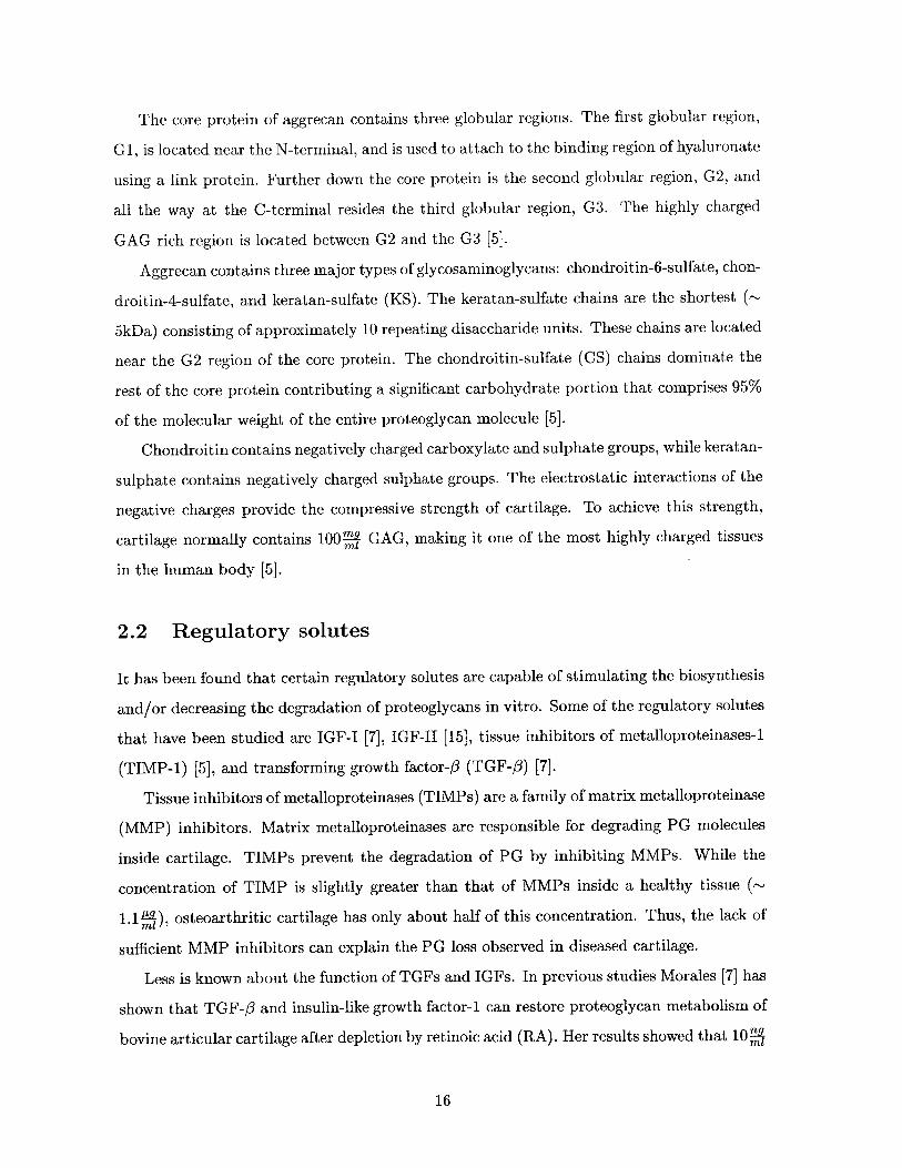
each having a slightly different function. The functions and quantities of the most important
types are summarized in Table 2.1 [11, 5, 12].
2.1.4 Proteoglycans
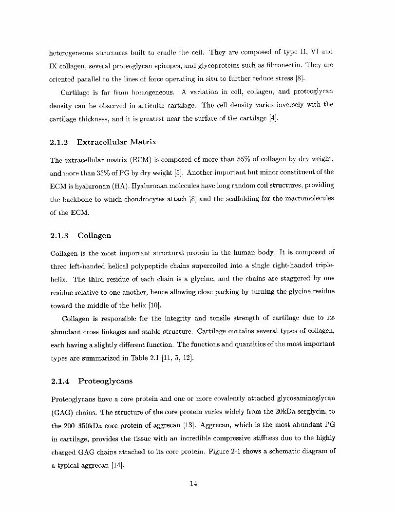
Proteoglycans have a core protein and one or more covalently attached glycosaminoglycan
(GAG) chains. The structure of the core protein varies widely from the 20kDa serglycin, to
the 200-35OkDa core protein of aggrecan [13]. Aggrecan, which is the most abundant PG
in cartilage, provides the tissue with an incredible compressive stiffness due to the highly
charged GAG chains attached to its core protein. Figure 2-1 shows a schematic diagram of
a typical aggrecan [14].
14
TYPE QUANTITY FUNCTION
II > 90% tensile strength, stiffness
VI < 1% lateral strength, flexibility
IX ~ 1% connections between fibrils
X < 1% unknown
XI ~-3% fibril formation
Table 2.1: Type, quantity, and function of the most relevant collagen molecules found inadult articular cartilage.
CS
pN-linked oligo-saccharide
Hyaluronatebinding region
0-linked oligo-saccharide
Link protein
CS = Chondroitin sulfateHyaluronate KS-ich region KS = Keratan sulfate
Figure 2-1: Schematic diagram of a typical aggrecan. (Figure has been taken from Heinegard
et al.)
15
The core protein of aggrecan contains three globular regions. The first globular region,
G 1, is located near the N-terminal, and is used to attach to the binding region of hyaluronate
using a link protein. Further down the core protein is the second globular region, G2, and
all the way at the C-terminal resides the third globular region, G3. The highly charged
GAG rich region is located between G2 and the G3 [5].
Aggrecan contains three major types of glycosaminoglycans: chondroitin-6-sulfate, chon-
droitin-4-sulfate, and keratan-sulfate (KS). The keratan-sulfate chains are the shortest (~
5kDa) consisting of approximately 10 repeating disaccharide units. These chains are located
near the G2 region of the core protein. The chondroitin-sulfate (CS) chains dominate the
rest of the core protein contributing a significant carbohydrate portion that comprises 95%
of the molecular weight of the entire proteoglycan molecule [5].
Chondroitin contains negatively charged carboxylate and sulphate groups, while keratan-
sulphate contains negatively charged sulphate groups. The electrostatic interactions of the
negative charges provide the compressive strength of cartilage. To achieve this strength,
cartilage normally contains 100' GAG, making it one of the most highly charged tissues
in the human body [5].
2.2 Regulatory solutes
It has been found that certain regulatory solutes are capable of stimulating the biosynthesis
and/or decreasing the degradation of proteoglycans in vitro. Some of the regulatory solutes
that have been studied are IGF-I [7], IGF-I [15], tissue inhibitors of metalloproteinases-1
(TIMP-1) [5], and transforming growth factor-3 (TGF-3) [7].
Tissue inhibitors of metalloproteinases (TIMPs) are a family of matrix metalloproteinase
(MMP) inhibitors. Matrix metalloproteinases are responsible for degrading PG molecules
inside cartilage. TIMPs prevent the degradation of PG by inhibiting MMPs. While the
concentration of TIMP is slightly greater than that of MMPs inside a healthy tissue (~
1.1YA), osteoarthritic cartilage has only about half of this concentration. Thus, the lack of
sufficient MMP inhibitors can explain the PG loss observed in diseased cartilage.
Less is known about the function of TGFs and IGFs. In previous studies Morales [7] has
shown that TGF-#3 and insulin-like growth factor-1 can restore proteoglycan metabolism of
bovine articular cartilage after depletion by retinoic acid (RA). Her results showed that 10i
16
of TGF-3 could restore 74% ± 24% of PG synthesis, 10O of IGF-I could restore 69 ±18% of
PG synthesis, and their combination could restore as much as 95±17% of PG synthesis in one
week. This suggests that TGF-# and IGF-I induces synthesis of proteoglycan aggregates
through a coordinated increase in hyaluronan and aggrecan [7, 15], and inhibits matrix
degradation induced by retinoic acid (RA) [6]. The fact that the PG loss was not recovered
after a week, however, indicates that other factors, such as other cytokines or mechanical
forces, might be involved in cartilage regeneration.
2.2.1 Insulin-like Growth Factors
IGF-I and IGF-II are single-chain polypeptides. As the name suggests, they are homologous
to both insulin and one another. They all share three disulfide bridges, 45% of their amino
acids, and have similar 3-D structures. Due to these similarities, the three peptides exhibit
similar functional and binding properties. For example, IGF-I has been shown to bind
insulin receptors [16]. The molecular weight of both growth factors are around 7.6kDa. The
molecular radius is approximately 1.2-1.3nm. IGF-I concentration in cartilage is between
1-50n9IGF . Figure 2-2 shows the stereo view of IGF-I and IGF-II.9tissue
It has been shown that the concentration of IGF-I is increased in osteoarthritic synovial
fluids. It has also been found that the concentration of IGF-I within normal cartilage is low
due to exclusion of large particles by the tissue; however, the concentration of the growth
factor in osteoarthritic cartilage can be an order of magnitude higher. Since higher levels of
growth factors were found to stimulate ECM regeneration, it is assumed that the increased
presence of IGF-I is a defensive measure of the body against the disease [17].
It has also been noticed that IGF-I reversibly binds to cartilage in much greater amounts
than would be predicted by cell receptor binding or the partition coefficient calculated
from the molecular size. Therefore, Schneiderman et al [15] hypothesized that IGF-I also
binds to matrix components. This was supported by their finding that cartilage contained
specific, probably cell receptor, and non-specific, probably PG, binding sites. Other research
suggests, that what Schneiderman et al. believed to be non-specific ECM binding sites could
be attributed to IGF binding proteins (IGF-BP) [18, 19].
17
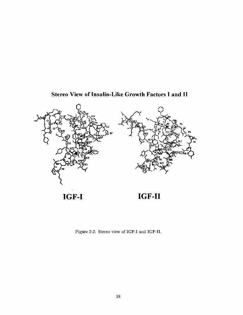
Stereo View of Insulin-Like Growth Factors I and 1.
IGF-I IGF-I
Figure 2-2: Stereo view of IGF-I and IGF-II.
18
Chapter 3
Transport Kinetics
3.1 Diffusion
Concentration gradients of a solute in a medium disappear over time. This phenomenon is
known as diffusion. The goal, is to characterize the diffusion of growth factors in cartilage
tissue, to help describe the kinetics of IGF-II, and possibly to use this knowledge to enhance
tissue growth and regeneration.
3.1.1 Fick's Laws
The diffusion of particles was first described empirically by Fick in 1855 [20]. Fick's First
Law describes the relationship between the flux of a chemical species and the concentration
gradient of that species [21]:
ri = -DVci, (3.1)
where ri ["f] denotes the flux of the ith species, D [cr2] is the diffusion coefficient, and
Vcj [""$8] is the concentration gradient of the ith species.
Experiments were done in a two-chamber system (Figure 3-1) in which the two chambers
have uniform, but distinct, concentrations of a labeled species. The concentration gradient
is zero everywhere except in the membrane that separates the two chambers. After an initial
lag time, Tlag, a steady-state, linear concentration profile is established in the membrane.
In steady-state, Fick's Law can be simplified to Fick's First Law for Membranes [21]:
19
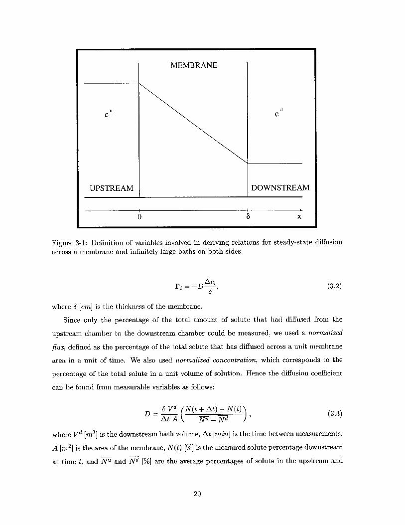
U
C
UPSTREAM
Figure 3-1: Definition of variables involved in deriving relations for steady-state diffusion
across a membrane and infinitely large baths on both sides.
Ac2Ti = -D A , (3.2)
where 6 [cm] is the thickness of the membrane.
Since only the percentage of the total amount of solute that had diffused from the
upstream chamber to the downstream chamber could be measured, we used a normalized
flux, defined as the percentage of the total solute that has diffused across a unit membrane
area in a unit of time. We also used normalized concentration, which corresponds to the
percentage of the total solute in a unit volume of solution. Hence the diffusion coefficient
can be found from measurable variables as follows:
6 Vd N(t + At) - N(t)(3At A ( Nu - Nd
where Vd [M3] is the downstream bath volume, At [min] is the time between measurements,
A [M2 ] is the area of the membrane, N(t) [%] is the measured solute percentage downstream
at time t, and Nu and Nd [%] are the average percentages of solute in the upstream and
20
MEMBRANE
dC
S X0
downstream chambers respectively.
If we consider a fixed control volume of some solution, the solute that enters through
the boundaries of this control volume must increase the concentration inside appropriately.
This relationship is described quantitatively by the continuity equation, also known as Fick's
Second Law [21]:
= DV 2 c. (3.4)09t
Fick's First and Second Laws provide enough information to describe the purely diffusive
transport kinetics of any solute in a medium.
3.1.2 Stokes-Einstein Model
It is possible to give a theoretical estimate of the diffusion coefficient in bulk media given
the radius of the solute and the viscosity of the medium. The model used to describe this
relationship was presented by Einstein in 1908 [22], and is known as the Stokes-Einstein
model. The Stokes-Einstein model capitalizes on the fact that in steady-state the velocity
of an average particle is constant; hence, the average of the forces acting on a particle must
cancel. This force balance equation is:
nT OX + fvii = 0, (3.5)Ox
where n = 1.38 - 10-23 is Boltzman's constant, T [K] is the absolute temperature, f [-]
is the drag coefficient, and vix [!] is the x-component of the particle's velocity with respect
to the medium. In this equation, the first term is the force acting on a single particle due
to a chemical potential gradient and the second term is due to fluid drag [23].
Generalizing Equation 3.5 to multiple particles in a control volume and using Stokes's
Law [24] to find the value of f, we see that:
KT KTD = - = (3.6)
f 67rpri
where p [s Pa] is the viscosity of the solution and ri [m] is the solute radius. This equation
is known as the Stokes-Einstein Equation.
The solutes used in the experiments were iodide and IGF-II; thus a theoretical estimate
21
0
Figure 3-2: Evolution of the concentration profile in a membrane due to a step increase in
the concentration on the left side of the membrane.
of the diffusion coefficient of both solutes could be calculated based on their radii using
the Stokes-Einstein Equation. The theoretical values of the diffusion coefficients at 90C in
water are:
cm26 cm2~cD = 9.56 - 10--7 C and DIGF = 1.65 - 10 -7 . (3.7)
s s
The actual value of the diffusion coefficient in cartilage is predicted to be much lower
than the bulk value, since the movement of the solute is hindered by steric and electrostatic
forces.
3.1.3 Non-Steady-State Kinetics
Steady state is not established instantaneously. It is easy to see that if the concentrations
of the baths are equal for t < 0, and a step in the left bath concentration is introduced at
t = 0, the concentration profile in the membrane will not be linear. Figure 3-2 shows the
evolution of the concentration profile within the membrane as modeled using Fourier series
approximations. The longest time constant of the Fourier series is the so-called steady-state
22
S X
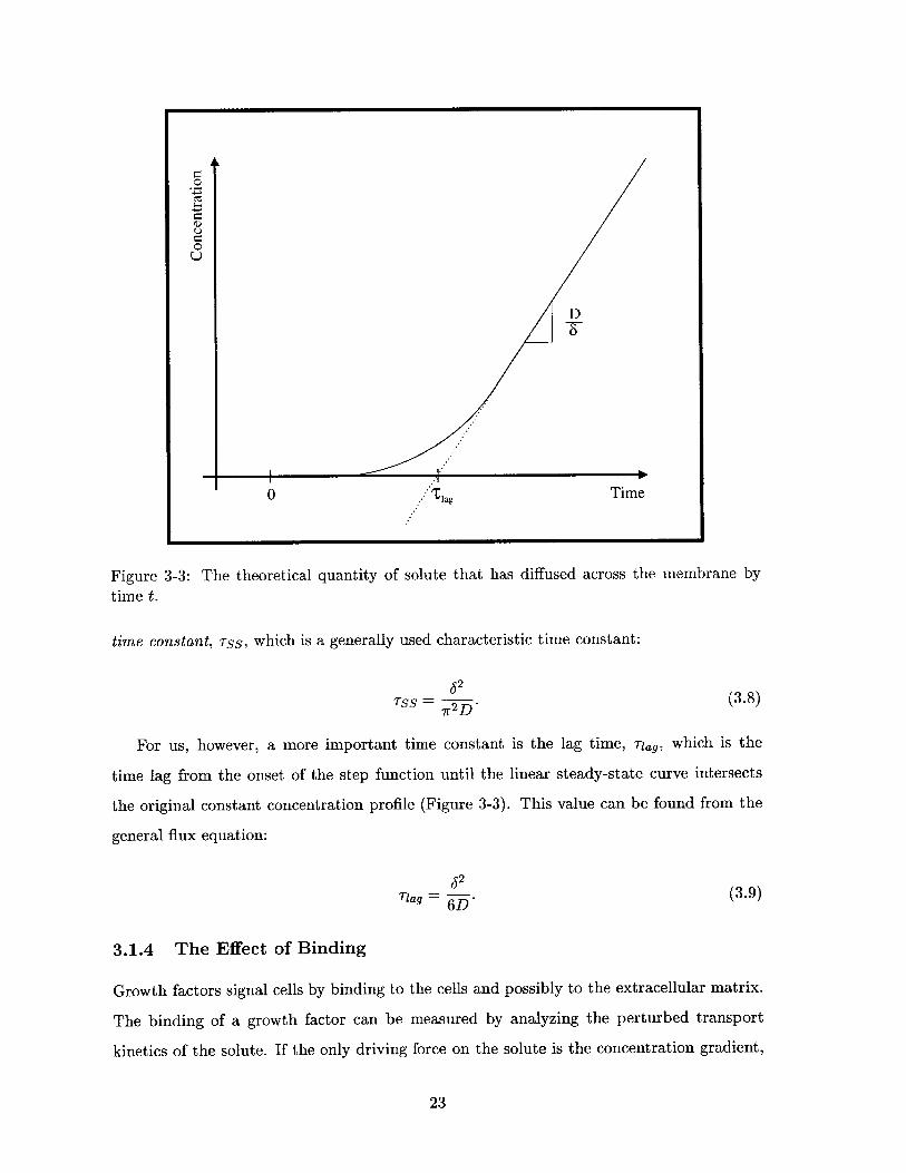
Figure 3-3: The theoretical quantity of solute that has diffused across the membrane by
time t.
time constant, Tss, which is a generally used characteristic time constant:
62TSS = - (3.8)
7r2D'
For us, however, a more important time constant is the lag time, riag, which is the
time lag from the onset of the step function until the linear steady-state curve intersects
the original constant concentration profile (Figure 3-3). This value can be found from the
general flux equation:
62Tiag = . (3.9)
6D*
3.1.4 The Effect of Binding
Growth factors signal cells by binding to the cells and possibly to the extracellular matrix.
The binding of a growth factor can be measured by analyzing the perturbed transport
kinetics of the solute. If the only driving force on the solute is the concentration gradient,
23
0t
$-
D-w
Time0 Tlag
a mathematical model can be derived that will allow us to calculate the percentage of
the growth factor that has bound to the tissue. This model also enables the analysis of
competitiveness between the various growth factors and the time scales of binding and
competition between the species.
The binding of a growth factor to the cartilage can be modeled as a second-order re-
versible reaction:
ka
S-+E ; ES, (3.10)
kd
where S represents the unbound solute (growth factor), E represents free binding sites, and
ES stands for solutes bound to a binding site.
In most cases, we can assume that the concentration of binding sites is a constant, CET,
and that steady-state is reached instantaneously; hence
kd _ CS CE and CET = CES + CE, (3-11)ka CES
where K [s*"] is the dissociation constant.
We can use Fick's Second Law to incorporate binding into the diffusion equation as
follows:
0 8 2cs(cs + CES) = D a 2 . (3.12)
Combining Fick's Second Law with the chemical binding term, we can find the new
expression for diffusion:
ac D a2CS= D eff .CS (3.13)at 1+ cFgrK OX 2 D f 2
(K+cs)2
Note that the new effective diffusion coefficient depends on the solute concentration and
is less then the actual diffusion coefficient. Binding of the solute to the tissue will therefore
slow transport across the tissue in the beginning, increasing the length of the lag time.
24
3.2 Migration
The application of an electric field to certain media creates a current. If this current is
due to the motion of ions, this phenomenon is called migration. The current induced by an
electric field depends on the strength and direction of the electric field and the properties
of the medium. For this study we assume that our medium, cartilage, is a homogeneous
ohmic conducting material, and that the system is electroquasistatic. A material is called
ohmic if it follows Ohm's Law (Section 3.2.1). A system is electroquasistatic if the time
varying magnetic field is negligible, and thus Faraday's induction law simplifies to
V x E(r,t) = - t ~0. (3.14)
This simplification allows us to introduce a new variable, 4 [V], known as the electrical
potential, defined as
E - -V4. (3.15)
3.2.1 Ohm's Law
A potential gradient will exert a force on charged particles, creating currents in conductors.
In ohmic media, the relationship between the strength of the electric field and the induced
current is linear and the constant coefficient is known as the conductivity of the medium.
Ohm's Law is hence
J = -o-eV4, (3.16)
where J is the current density [-A], o-e is the conductivity of the material, and V4 is the
potential gradient [M].
The movement of ions through a medium due to an applied electric field is known
as electrophoresis. Electrophoresis can be used to enhance the transport of ions to their
destination. In some of the experiments we tested the enhanced transport of iodide and
IGF-II across cartilage tissue.
The conductance of a solution is related to the ionic concentration of the solutes. This
25
relationship can be expressed as:
o- = IzilFuici, (3.17)
where i denotes a specific charged species, zi is the valence of the species, F is Faraday's
constant (F = 96, 500 moes ui is the mobility of the ith species, and ci is the concentration
of the ith species.
In the calculations it was assumed that cartilage is an ohmic conductor under the ex-
perimental conditions.
3.3 Convection
Pressure gradients can induce fluid flow in permeable materials. This fluid flow in a medium
is called convection.
3.3.1 Darcy's Law
Convection induced by a pressure gradient can be described by a linear equation in most
materials, similarly to diffusion and migration. This equation is known as Darcy's Law and
the constant coefficient is the Darcy permeability, n [ M:
U = -KVP, (3.18)
where U is the velocity (i.e. volume flux) of the solvent [7], and VP is the pressure gradient
in the solvent [P].
In the calculations it was assumed that cartilage obeys Darcy's law under the experi-
mental conditions.
3.4 Coupled Transport Equations
In the previous section we introduced Fick's Law (Eq. 3.1), Ohm's Law (Eq. 3.16), and
Darcy's Law (Eq. 3.18). Each one of these laws relates the gradient of an energy source
to the movement of either solutes or the fluid. These relationships become more complex,
however, if we consider the coupling between them.
26
3.4.1 The Transport Equations
A potential gradient will induce a current, hence the motion of ions in a solution. The
motion of the ions in turn can set the fluid into motion, giving rise to a net fluid flow.
Furthermore, the motion of ions constitutes a flux. Hence a potential gradient can create
current, fluid flow, and flux.
Similarly, a coupling between chemical and mechanical forces also exists. Both a chem-
ical gradient and a pressure gradient are capable of inducing currents, fluid flow and sol-
vent flux. This relationship can thus be given using phenomenological equations of non-
equilibrium thermodynamics [251:
J -kul ki2 ki3 V4b
Ti k21 -k 22 k23 Vci (3.19)
U k3 i k32 -k 33 VP
where the kiy are the constant coupling coefficients with appropriate dimensions. Darcy's,
Ohm's, and Fick's laws (Equations 3.18, 3.16, and 3.1) are all special cases of Equation 3.19.
The coupling coefficient matrix has some important properties. As the signs indicate,
the diagonal elements of the coupling coefficient matrix are all negative. Since the diagonal
elements correspond to Darcy's, Ohm's, and Fick's laws, it can be seen that the sign is there
to account for "motion" down the "potential" gradients. The second interesting property
of the matrix is its symmetric nature. The symmetry exists because from the standpoint
of nature it is irrelevant whether a potential drop creates an ionic flow, hence a fluid flow
and thus an "effective pressure" or whether a pressure drop creates a creates fluid flow,
hence ionic flow, thus an "effective potential." Therefore the coupling coefficient matrix is
symmetric, with negative diagonal elements.
Using the above it is possible to calculate the kinetics of solute and solution movement in
cartilage. The constant coefficients, however, depend on the composition [26], experimental
conditions (pH, ionic strength, etc.), and the orientation of the tissue [27]. In order to be
able to quantify experiments carried out on cartilage and find the coupling coefficients, all
of the above conditions must be controlled.
The constitutive law given in Equation 3.19 combines electrical, chemical, and mechan-
27
ical effects, and is thus rarely used in calculations due to its complexity. The single matrix
equation combines 3 vector equations, each consisting of 3 components; thus it consists of
9 equations, 9 unknown constants, and 18 variables. To reduce this complexity, the effects
of electrical, chemical, and mechanical forces are usually either studied separately, resulting
in Ohm's, Fick's and Darcy's laws respectively, or pairwise.
28
Chapter 4
Previous Work
This section discusses the relevant previous work that shows the stimulation of cartilage
biosynthesis in response to enhanced transport due to dynamic electrical and mechanical
loading. Furthermore, previous equilibration and transport kinetic studies involving IGF-I
and IGF-II in adult bovine cartilage will also be described.
4.1 Stimulation of Biosynthesis by Increased Perfusion Rate
Increased perfusion rate has been shown to stimulate biosynthesis. This has been done by
increasing tissue perfusion using dynamic mechanical loading [28, 29] or changing electrical
field [30, 31, 26, 32]. The biosynthesis was monitored in most cases by 3 H-proline uptake
by amino acid and protein synthesis and 3 5S-sulfate incorporation for GAG synthesis.
It has been found that, at certain frequencies and amplitudes, dynamic mechanical
loading of cartilage can cause an increase or inhibition of biosynthesis [28, 29]. The optimal
frequency and amplitude for the synthesis of both proteins and GAG chains correspond well
to the frequencies and amplitudes at which maximal fluid flow is achieved, but still no cell
damage occurs due to the high stresses caused by the loading. The same type of stimulation
was found when changing electrical fields were used [31, 32].
4.2 IGF-I and IGF-II Competition for Binding Sites
IGF-I and IGF-II have similar size and structure; hence it can be presumed that they might
exhibit similar binding characteristics as well. A simple way to test whether the two growth
29
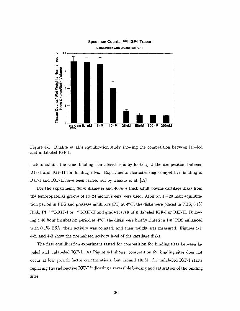
Specimen Counts, 1251 IGF-I Tracer
Competition with Unlabelled IGF-l
o 12
N
E >
0
0
o
.~0
0
NoCoIdO.1nM 1M 1OnM 25nM 50nM 1OOnM 200nMIGF-1
Figure 4-1: Bhakta et al.'s equilibration study showing the competition between labeledand unlabeled IGF-I.
factors exhibit the same binding characteristics is by looking at the competition between
IGF-I and IGF-II for binding sites. Experiments characterizing competitive binding of
IGF-I and IGF-II have been carried out by Bhakta et al. [19]
For the experiment, 3mm diameter and 400pm thick adult bovine cartilage disks from
the femoropatellar groove of 18-24 month steers were used. After an 18-20 hour equilibra-
tion period in PBS and protease inhibitors (PI) at 40C, the disks were placed in PBS, 0.1%
BSA, PI, 12 5 I-IGF-I or 1 2 5 I-IGF-II and graded levels of unlabeled IGF-I or IGF-JI. Follow-
ing a 48 hour incubation period at 4'C, the disks were briefly rinsed in 1ml PBS enhanced
with 0.1% BSA, their activity was counted, and their weight was measured. Figures 4-1,
4-2, and 4-3 show the normalized activity level of the cartilage disks.
The first equilibration experiment tested for competition for binding sites between la-
beled and unlabeled IGF-I. As Figure 4-1 shows, competition for binding sites does not
occur at low growth factor concentrations, but around 10nM, the unlabeled IGF-I starts
replacing the radioactive IGF-I indicating a reversible binding and saturation of the binding
sites.
30
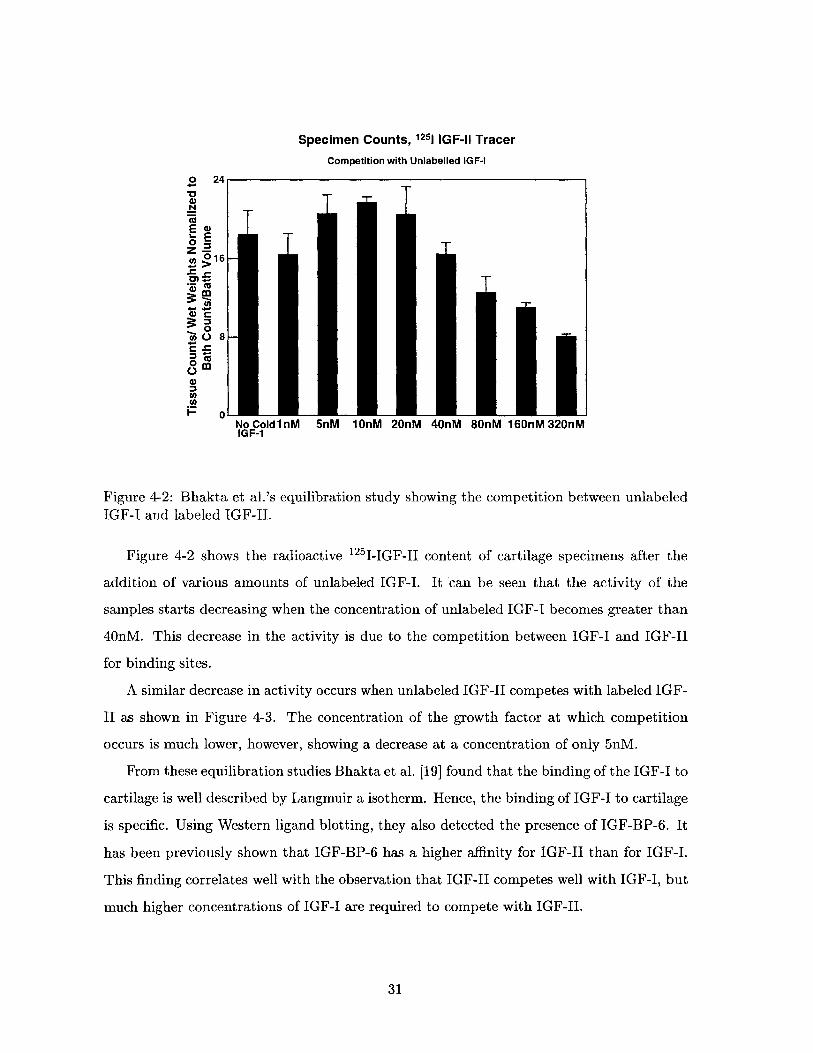
Specimen Counts, 1251 IGF-I1 Tracer
Competition with Unlabelled IGF-10 24
~ 16
0)
0=z 8
CO
A
0- ANoCold1nM 5nM 1OnM 20nM 40nM 80nM 160nM32OnMIGF-1
Figure 4-2: Bhakta et al.'s equilibration study showing the competition between unlabeledIGF-I and labeled IGF-II.
Figure 4-2 shows the radioactive 12 5 I-IGF-II content of cartilage specimens after the
addition of various amounts of unlabeled IGF-I. It 'can be seen that the activity of the
samples starts decreasing when the concentration of unlabeled IGF-I becomes greater than
40nM. This decrease in the activity is due to the competition between IGF-I and IGF-II
for binding sites.
A similar decrease in activity occurs when unlabeled IGF-I competes with labeled IGF-
II as shown in Figure 4-3. The concentration of the growth factor at which competition
occurs is much lower, however, showing a decrease at a concentration of only 5nM.
From these equilibration studies Bhakta et al. [19] found that the binding of the IGF-I to
cartilage is well described by Langmuir a isotherm. Hence, the binding of IGF-I to cartilage
is specific. Using Western ligand blotting, they also detected the presence of IGF-BP-6. It
has been previously shown that IGF-BP-6 has a higher affinity for IGF-II than for IGF-I.
This finding correlates well with the observation that IGF-II competes well with IGF-I, but
much higher concentrations of IGF-I are required to compete with IGF-II.
31
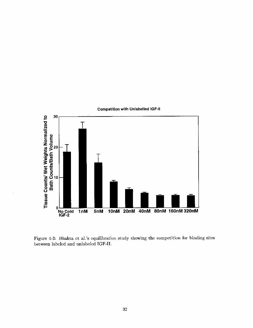
Competition with Unlabelled IGF-l
T
- T
T
No Cold 1M 5nM 1OnM 20nM 40nM 8OnM 160nM32OnMIGF-2
Figure 4-3: Bhakta et al.'s equilibration study showing the competition for binding sites
between labeled and unlabeled IGF-II.
32
o 30
E .0NE
2020
M M
45 0 10
0
0
0
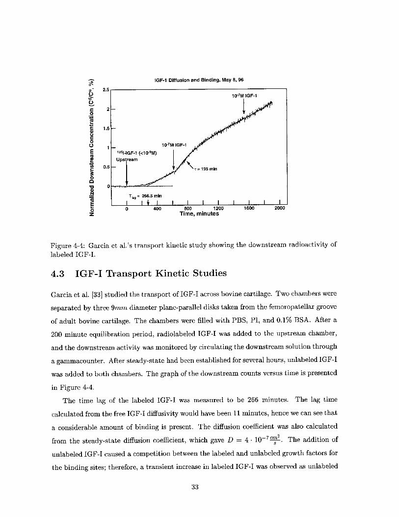
IGF-1 Diffusion and Binding, May 8, 96
2.510-7M IGF-1
*0 S 2-
C 1.5 -0
1 _ 10-7M IGF-1E 1251-IGF-1 (<10-9M)( UpsreamC 0.5 = 195 min
0*~ 0
Tlg = 266.5 min
E0 0 400 800 1200 1600 2000z Time, minutes
Figure 4-4: Garcia et al.'s transport kinetic study showing the downstream radioactivity of
labeled IGF-I.
4.3 IGF-I Transport Kinetic Studies
Garcia et al. [33] studied the transport of IGF-I across bovine cartilage. Two chambers were
separated by three 9mm diameter plane-parallel disks taken from the femoropatellar groove
of adult bovine cartilage. The chambers were filled with PBS, PI, and 0.1% BSA. After a
200 minute equilibration period, radiolabeled IGF-I was added to the upstream chamber,
and the downstream activity was monitored by circulating the downstream solution through
a gammacounter. After steady-state had been established for several hours, unlabeled IGF-I
was added to both chambers. The graph of the downstream counts versus time is presented
in Figure 4-4.
The time lag of the labeled IGF-I was measured to be 266 minutes. The lag time
calculated from the free IGF-I diffusivity would have been 11 minutes, hence we can see that
a considerable amount of binding is present. The diffusion coefficient was also calculated
from the steady-state diffusion coefficient, which gave D = 4 - 10-7 -2. The addition of
unlabeled IGF-I caused a competition between the labeled and unlabeled growth factors for
the binding sites; therefore, a transient increase in labeled IGF-I was observed as unlabeled
33
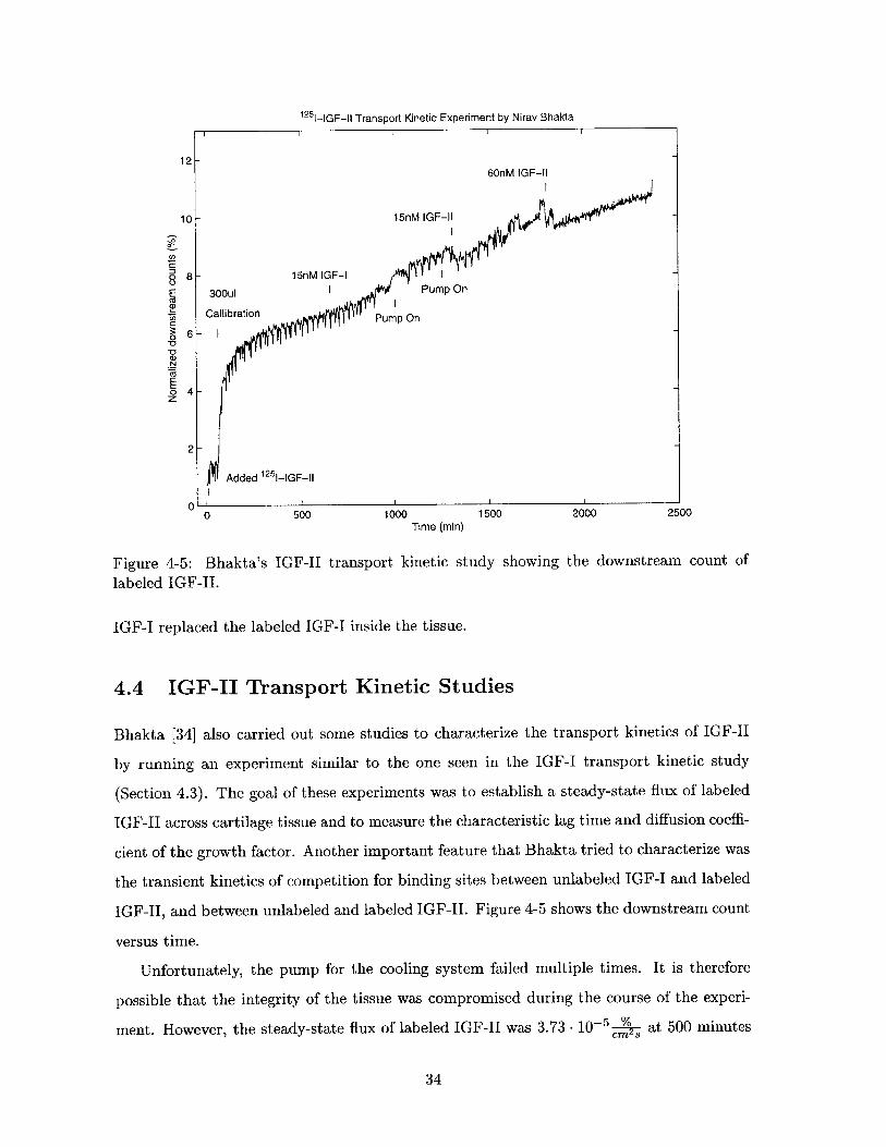
125 -IGF-Il Transport Kinetic Experiment by Nirav Bhakta
12-60nM IGF-11
10-15MGFI
o - 15nM IGF-1
UI
- CallibrationPupo
2
Added 125-IGF-II
0 500 1000 1500 2000 2500Time (min)
Figure 4-5: Bhakta's IGF-II transport kinetic study showing the downstream count oflabeled IGF-II.
IGF-I replaced the labeled IGF-I inside the tissue.
4.4 IGF-II ransport Kinetic Studies
Bhakta [34] also carried out some studies to characterize the transport kinetics of IGF-II
by running an experiment similar to the one seen in the IGF-I transport kinetic study
(Section 4.3). The goal of these experiments was to establish a steady-state flux of labeled
IGF-II across cartilage tissue and to measure the characteristic lag time and diffusion coeffi-
cient of the growth factor. Another important feature that Bhakta tried to characterize was
the transient kinetics of competition for binding sites between unlabeled IGF-I and labeled
IGF-II, and between unlabeled and labeled IGF-II. Figure 4-5 shows the downstream count
versus time.
Unfortunately, the pump for the cooling system failed multiple times. It is therefore
possible that the integrity of the tissue was compromised during the course of the experi-
ment. However, the steady-state flux of labeled IGF-II was 3.73 - 0- at 500 minutes
34
into the experiment and 4.32 - 10--5 cm- at 2000 minutes into the experiment. Since thecm 8
difference between the steady-state fluxes is small, it is safe to assume that the tissue did
not degrade significantly even though the cooling system was not fully operational.
At 650 minutes, 15nM cold IGF-I was added to both chambers. This change did not
seem to have any affect on the transport kinetics of labeled IGF-II. This suggests that no
competition between IGF-I and IGF-II for binding sites exists at the given concentration
levels. This is in agreement with the equilibration studies done earlier by Bhakta et al. [19],
in which he determined that competition occurs only for IGF-I concentrations greater than
40nM.
The "bumps" in the curve were probably caused by the recurring difficulties with the
cooling apparatus and make the middle section of the data unusable. Hence it is impossible
to make a quantitative analysis of the competition for binding sites between the different
growth factors.
The data further suggest a possible decrease in the downstream radioactivity after the
addition of 15nM IGF-II and 60nM IGF-II. At that point it was yet unknown what might
have caused labeled IGF-II to diffuse backwards from the downstream bath to the upstream
bath. It was later discovered that this error is probably due to an error in the protocol and
should not occur under ideal conditions (Section 7.1.3).
35
Chapter 5
Experimental Controls
5.1 Testing Binding to the Radiomatic
Binding to the detector of the radiomatic was a serious concern. To test how much radioac-
tive IGF is capable of binding to the detector, a 10% dilution of an upstream sample (after
an experimental run) was run through the detector. The dilution was carried out using
diH2 0, and the circulation of the diluted sample began at 316 minutes (Figure 5.1).
As was expected, a significant jump was observed in the measured activity to 1650cpm;
however, the activity continued to increase for over 16 hours to a maximum of approximately
2600cpm at 1350 minutes. Since our sample contained only 0.01% BSA and 15mM NaCl,
more BSA and NaCl was added to the solution to create a 0.1% BSA and 150mM NaCl
solution at 1350 minutes. The effects were dramatic. The radiation dropped by half in
about 10 hours, and finally settled around 1000cpm. Further addition of BSA and NaCl
did not reduce binding significantly.
This short control experiment demonstrated the relevance of BSA and high salt concen-
trations in the system. It also demonstrated that attention must be payed to the experi-
mental setup in order to ensure that I am truly measuring transport through and binding
to the sample tissue and not experimental error due to non-specific binding.
5.2 Resistance of the Baths
The conductivity of the baths can be calculated from the ionic concentrations using equa-
tion 3.17:
36
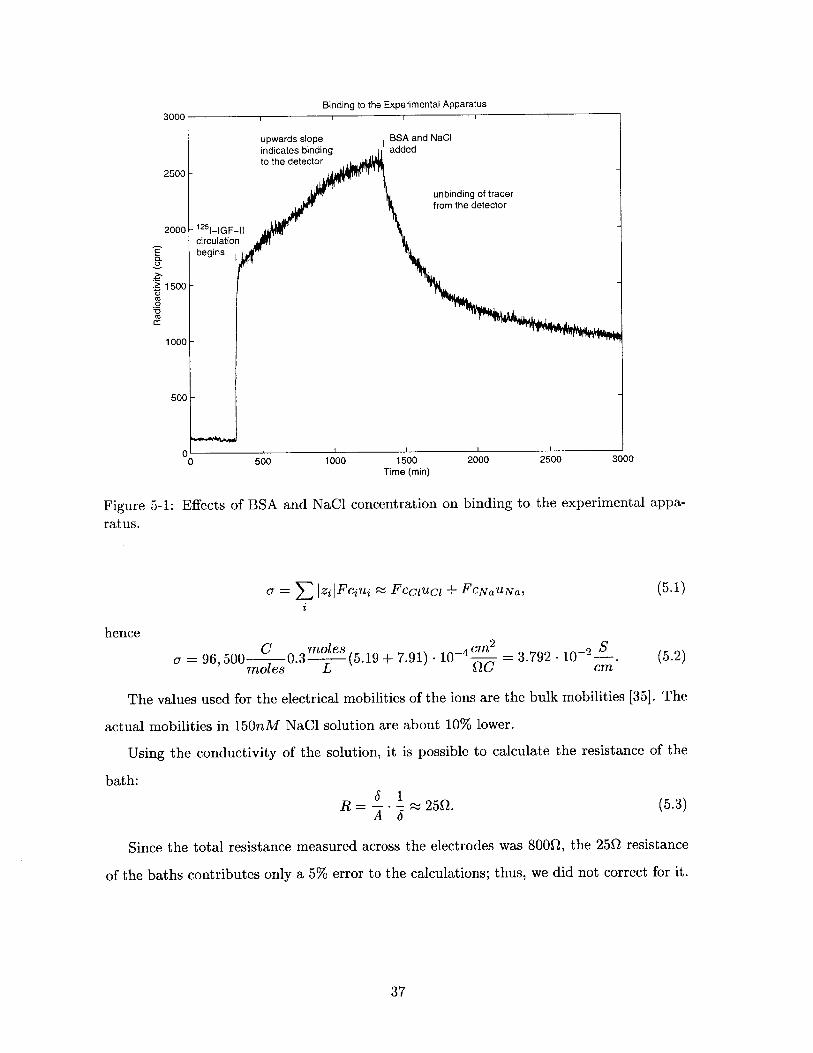
Binding to the Experimental Apparatus
CL
.~1500
0M0r
0 500 1000 1500 2000 2500 3000Time (min)
Figure 5-1: Effects of BSA and NaCl concentration on binding to the experimental appa-
ratus.
o- = zj|Fcjnj _ Fccluci + FCNaUNa, (5.1)
hence
o- = 96,500 C 0.3moles (5.19 + 7.91) - 10 -4 cm2 = 3.792 - 10-2 S (5.2)moles L QC cm
The values used for the electrical mobilities of the ions are the bulk mobilities [35]. The
actual mobilities in 150nM NaCl solution are about 10% lower.
Using the conductivity of the solution, it is possible to calculate the resistance of the
bath:6 1
R = ~25Q. (5.3)A 6
Since the total resistance measured across the electrodes was 800Q, the 25Q resistance
of the baths contributes only a 5% error to the calculations; thus, we did not correct for it.
37
Chapter 6
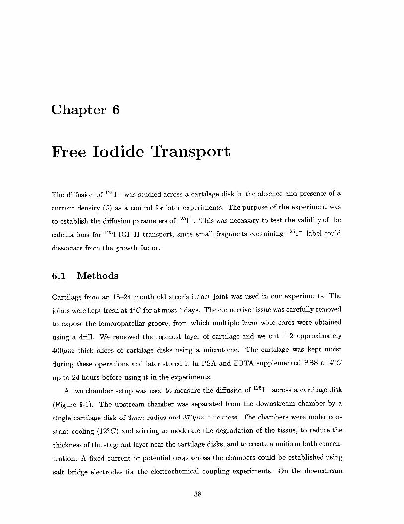
Free Iodide Transport
The diffusion of 1251- was studied across a cartilage disk in the absence and presence of a
current density (J) as a control for later experiments. The purpose of the experiment was
to establish the diffusion parameters of 125I-. This was necessary to test the validity of the
calculations for 125 I-IGF-1 transport, since small fragments containing 1251- label could
dissociate from the growth factor.
6.1 Methods
Cartilage from an 18-24 month old steer's intact joint was used in our experiments. The
joints were kept fresh at 40C for at most 4 days. The connective tissue was carefully removed
to expose the femoropatellar groove, from which multiple 9mm wide cores were obtained
using a drill. We removed the topmost layer of cartilage and we cut 1-2 approximately
400pLm thick slices of cartilage disks using a microtome. The cartilage was kept moist
during these operations and later stored it in PSA and EDTA supplemented PBS at 4'C
up to 24 hours before using it in the experiments.
A two chamber setup was used to measure the diffusion of 125I~ across a cartilage disk
(Figure 6-1). The upstream chamber was separated from the downstream chamber by a
single cartilage disk of 3mm radius and 370pm thickness. The chambers were under con-
stant cooling (120C) and stirring to moderate the degradation of the tissue, to reduce the
thickness of the stagnant layer near the cartilage disks, and to create a uniform bath concen-
tration. A fixed current or potential drop across the chambers could be established using
salt bridge electrodes for the electrochemical coupling experiments. On the downstream
38
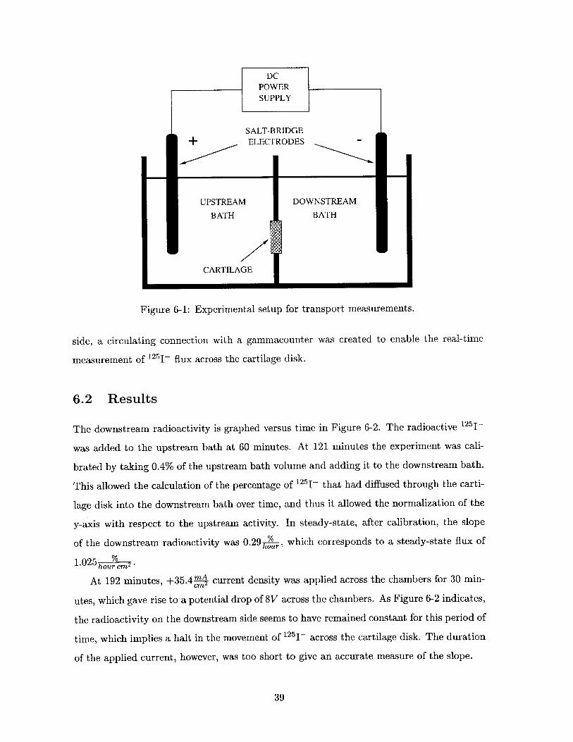
Figure 6-1: Experimental setup for transport measurements.
side, a circulating connection with a gammacounter was created to enable the real-time
measurement of 125I flux across the cartilage disk.
6.2 Results
The downstream radioactivity is graphed versus time in Figure 6-2. The radioactive 1251-
was added to the upstream bath at 60 minutes. At 121 minutes the experiment was cali-
brated by taking 0.4% of the upstream bath volume and adding it to the downstream bath.
This allowed the calculation of the percentage of 1251- that had diffused through the carti-
lage disk into the downstream bath over time, and thus it allowed the normalization of the
y-axis with respect to the upstream activity. In steady-state, after calibration, the slope
of the downstream radioactivity was 0.29 %u, which corresponds to a steady-state flux of
1.025hour cm2
At 192 minutes, +35.4% current density was applied across the chambers for 30 min-
utes, which gave rise to a potential drop of 8V across the chambers. As Figure 6-2 indicates,
the radioactivity on the downstream side seems to have remained constant for this period of
time, which implies a halt in the movement of 125 I-- across the cartilage disk. The duration
of the applied current, however, was too short to give an accurate measure of the slope.
39
Electrophoresis of 1251 Through Cartilage
0.4
CL
02-0EE
Add 5AppliedCUE +1lOmA
0
CO 0.4%1 DCalibration
0.5t125)Added I
0L0 100 200
Figure 6-2: Downstream radioactivitytilage during electrophoresis.
300Time (min)
for 125j- transport experiment across articular car-
40
At 305 minutes, -35.4% was applied for 30 minutes, giving rise to -8V across the
chambers. The increase in the slope of the downstream radioactivity from 0.29 to
1.74 is a clear indication of a six fold increase in the 1251- flux from 1.025o c7m2 to174 r horcm
6.148 %cm due to electrophoresis.hour cm2
Finally, at 489 minutes, +10mA was applied for another 60 minutes to establish a
more accurate measure of the altered slope. The slope for +10mA, however, remained
approximately 0 .
The resistance of the cartilage disk remained 800Q for all electrochemical experiments.
This was measured by taking the ratio of the potential drop and the current across the
chambers.
6.3 Discussion
Using the data found in the experiment we can calculate the effective diffusion coefficient of
1251- and the electrical conductance of the cartilage if we assume that the pressure difference
between the two chambers is negligible. The coupling between the current density and the
solute flux due to a potential and a chemical gradient can be described using the following
equation from section 3.4:
J I -ku k12 A 1II I (6.1)6
r k21 - k22 Ac
This equation is equivalent to Equation 3.19 evaluated at AP = 0. J (,) is the
current density across the sample tissue, F ( m) is the normalized flux of iodide across
the membrane, A'1 (V) is the potential drop across the baths, Ac (%) is the normalized
concentration difference of 125I~ between the baths, and the constants kij are the coupling
coefficients.
The values of J, A4, Ac, and F are known from the experiments, hence we can easily
find the value of each coupling coefficient, kij. Once the values of the coupling coefficients
are known, we can use Fick's Law (Eq. 3.1), which applies in the special limiting case when
AG = 0, to relate the value of k22 to the diffusion coefficient, D.
41
Current Density, J Normalized Flux, r Potential Drop, A1b Concentration Drop, Ac
I o04 1.025%cmT hr cmW2 CM3
II 3 5 .4 mArm2 -8V -1.947
III -35.4 4 6.148 rm2 8V -1.96 %3
Table 6.1: Experimental results of labeled
tential gradients.
iodide transport due to concentration and po-
Ac AcIF = -D = -k227, (6.2)
hence
k22 = D. (6.3)
We can similarly relate k1u to the electrical conductance o- using Ohm's Law, which
applies to the special case when Ac = 0.
(6.4)
hence
kr = -. (6.5)
Table 6.1 shows the flux of 125I- across the cartilage disk with respect to the applied
current density and the potential drop. Using these values we can calculate the four coupling
coefficients as follows:
* Since the value of Ac can be considered a constant during the experiment, we can find
ku and k2 1 by taking the difference of the current densities and the fluxes respectively.
J1 - J2 =kl, (6.6)
hence using the measurements of case II and III we find that
J1 -J 2 70.8 m 1k1u = 6 - J2 = 370pm - cm = 1.637. 10 .c
A4)2 - A 1 I 16V Qcm(6.7)
42
J = o-E = -o- -ku,
Furthermore, we know that
(A41 - A 2)F1 - F2 = k21 C,
hence using the measurements of case I and III we find that
IF - r3 -6.148 - 2' %k21=6. _ 2 370pm - hr cm 3.949 - 10-
A42 - A 43 -16V s cmV
(6.8)
(6.9)
* Since we now know the value of k1n and k21 , we can directly find the value of k1 2 and
k22 using the equation for the current density and the flux and the measurements of
case II and III respectively.
= - J2 + kn A4 2 _ 340pm - 35.4 mA - 1.637 10~ 4 1 8Vk12 = c - .CM 9 %CM
12 ACcm
= 5.436-10-2 mA cm2
(6.10)
and
k2 1 A3 - 6 - F3 _ 3.949 .10-6 % 8V- 370pm -6.148 r 222 hr cm
2
22 -Ac-1.95= 1.620-10_5 cm2
(6.11)
From the values of the coupling coefficients we can now calculate the diffusion coefficient
and the electrical conductivity of cartilage using equations 6.3 and 6.5.
D = =1.620 - 10-5
41o= k1 = 1.637 10-4 .
Ocm
(6.12)
(6.13)
Note that Fick's Law does not directly apply in an open voltage system even if no
current density is applied across the tissue. The diffusion of the charged ions can create a
Donnan potential at the boundaries, reducing the effective diffusion coefficient. To find the
effective diffusion coefficient for open voltage diffusion, we can use Equation 6.1 with J = 0.
1 k2 1A - k2 2 Ac _ Acr = = -Def f , (6.14)
43
and
and since J = 0 we can also write:
0 = -kuA<D + k12 Ac, (6.15)
hence:ki2 A c
F = (k2 1 - k2 2 ) , (6.16)
giving rise to an effective diffusion coefficient of:
k12 2 % 5.436- 10-2 mA cm 2
Def f = k22 - k21 = 1.620 - 10-5 - 3.949 -10-6 %1 , (6.17)ku s scmV 1.637-10-4 (.1
hencec2
Deff = 1.489 - 10-5 . (6.18)S
As we can see, the effective diffusivity of labeled iodide is smaller than the actual value,
because the potential drop created by the flux of ions across the tissue exerts a counter
force on the solutes. We can similarly calculate an effective conductivity of the tissue and
find that the effective conductivity is also smaller than the actual value.
44
Chapter 7
IGF Transport Through Cartilage
This chapter is dedicated to the insulin-like growth factor transport experiments. We
present and describe the experiments in chronological order, discuss the results of each
one, and analyze the changes made to the protocol for the following experiment.
7.1 Experiment 1.
The previous IGF-II transport kinetic experiment done by Bhakta [34] (Section 4.4) showed
some peculiar results. It was unknown at the time whether these results characterized
some unaccounted for phenomena or whether they were a result of experimental artifacts.
Therefore, the goal was to repeat these experiments and analyze the results.
7.1.1 Methods
For the transport kinetic study human recombinant (3-f 2 5 I]iodotyrosyl) insulin-like growth
factor-2 from Amersham Pharmacia Biotech was used. The lyophilized peptides were re-
constituted using 300pl of 0.01M Acetic Acid and 0.1% BSA. A 5p1l aliquot of the labeled
IGF-II was first analyzed for its activity level and found that the sample had 2.286. 10 4 CPM .
For the experiment we used 250pl of IGF-II, which had a total activity of 5.715-106 cpm, and
should correspond to 2.1pmoles of IGF-II. Since the purity of the material had been found
unacceptable on previous accounts, a standard cleaning procedure was used to establish the
desired purity.
The first step of purification of the reconstituted labeled IGF-II was to run it through
a 30cm by 0.6cm Sephadex-G50 column at a flow rate of 1.8w. We collected 100 fractions
45
Gamma Count for 1251-IGF-Il -- Experiment 1x 1053r
*
D
0 1.5-CO)
EE* *cz
* 125
0.5BSA residues
A*
0 20 40 60 80 100 120Sample number
Figure 7-1: Downstream radioactivity for 125I-IGF-II before cleaning. The first peak around
sample 30 contains the labeled large aggregates, the second peak around sample 60 has the
labeled IGF-II, and the third peak around fraction 75 includes the dissociated free labels.
of 0.3ml each to separate the free labels and the large aggregates from the sample. In
Figure 7-1, the activity of the fractions are plotted versus the order of the fractions. The
first peak around fraction 30 corresponds to large aggregates of BSA residues, radioactive
iodide, and labeled IGF-II. The second, much larger, peak around fraction 55 corresponds to
labeled IGF-II, and the third smaller peak around fraction 75 contains the free label and/or
small fragments containing 125I label. The areas under each peak indicate that the labeled
iodide content of the sample was approximately 8%, and the aggregate concentration was
even lower. For this experiment, we collected fractions 48 through 65, which contained the
labeled IGF-II, and further purified and concentrated the peptides using a centricon-3 filter
(with a nominal 3, 000MW cut-off). This process removed any remaining free label and
allowed the exchange of the buffer.
The chamber setup was similar to the one used in the free labeled iodide experiment.
The only changes made to the system were the removal of the salt bridge electrodes and
the use of three 340pm thick cartilage disks of 3mm radii instead of a single disk.
46
125 _-IGF-l1 Transport and Binding --- Experiment 1
5
4.5
F. 60nM IGF-11U)
15nM IGF-10*0
0 3 - 0.57%-N Calibration
02.5-
Added
2 12 51-IGF-l
1.5 -Lag time
. I IIIIIII0 500 1000 1500 2000 2500 3000 3500 4000 4500
Time (min)
Figure 7-2: The plot shows the 125 I-IGF-II downstream radioactivity versus time for Ex-
periment 1, which describes the transport and binding kinetics of the growth factor in
cartilage.
The protocol was also similar to that of the free labeled iodide experiment. After a bath
equilibration period (0-493min), we added the concentrated 125 I-IGF-II to the upstream
bath and waited until a constant steady-state flux across the cartilage was established
(Figure 7-2). At 902min, the downstream gamma counts were calibrated using 200p1 or
0.57% of the upstream bath. We added 15nM of unlabeled IGF-I at 1331 minutes, 15nM of
unlabeled IGF-II at 1827 minutes, and finally 60nM of unlabeled IGF-II at 2499 minutes,
to quantify the kinetics of competitive binding of IGF-II to cartilage through hindered
transport.
7.1.2 Results
The normalized downstream concentration of IGF-II is shown in Figure 7-2. As the time
scale of the experiment indicates, the experiment lasted 75 hours due to the low diffusion
rate of radioactive IGF-II. Since the radioactivity of the labeled IGF-II was lower than that
of the labeled iodide in the previous experiment, the background noise was quite noticeable.
47
I I I I I I - I5.5
The two chambers were allowed to equilibrate for several hours. After the radioactivity
on the downstream side had stabilized at a constant value, we added the labeled IGF-II
to the upstream chamber. The downstream radioactivity established a steady-state linear
profile after a lag time of a 180 minutes.
From the linear portion of the graph right after calibration, we could measure the steady-
state flux of 125 1-IGF-II across the chambers: 2.17 - 10-5c mY. By the end of the 75 hours,
however, the flux had tapered down to 1.47- 10-5 -. It is not yet established why that
flux decreased by 30%. It is hypothesized that the decrease in the upstream concentration,
binding of the growth factor to the experimental apparatus, and stirring might all play a
role in this anomaly.
The dissociation of the 125j- label from the IGF-II was measured using the chromato-
graphic analysis of a 300pl sample at 3026 minutes from the upstream bath: a 30cm
Sephadex G-50 column was used with a flow rate of 1.8m, collecting 100 fractions of
0.3ml each as before. The fractions were then analyzed by a gamma counter. Figure 7-3
shows the activity of the fractions collected from the column. Similarly to the previous
chromatography done during the purification process, the first peak around fraction 30 cor-
responds to labeled BSA aggregates, the second peak around fraction 55 corresponds to
labeled IGF-II, and the third peak around fraction 75 corresponds to free label. As the
areas under the peaks demonstrate, the free label accounted for 20% of the total activity.
This indicates a considerable dissociation of 125 I-IGF-II to free label and unlabeled IGF-II.
7.1.3 Discussion
As the chromatography of the labeled IGF-II indicated (Figure 7-1), the free labeled iodide
content of the peptide was only approximately 8%. The concentration of the larger aggre-
gates was even lower. This prompted the question of whether the cleaning procedure was
necessary. Although we continued to clean the IGF-II in the next experiment, we decided
to eliminate the cleaning for later experiments if the quality of the labeled IGF-II proved
to be adequate.
The greatest problem was the high percentage of dissociated labeled iodide at the end of
the experiments. It was hypothesized that the high level of dissociation can be attributed
to inefficient cooling; hence, the next experiment was set up inside a refrigerator at 9C.
As Figure 7-2 shows, there was a drop in the count after the addition of unlabeled IGF-II
48
Gamma Count for 125 -IGF-II --- Experiment 1
1251-IGF-Il- -
500 -
Ea.400 -
E 300-
E
200
100
backgroundnoise
BSA residues
0 10 20 30 40 50Sample number
* *
*
*
*
*
*
*%l
-*
*
*
60 70 80 90
Figure 7-3: Chromatography of an upstream sample taken 3100 minutes into the first IGF-
II transport kinetic experiment. The first peak around fraction 30 corresponds to BSA
aggregates with 125I or labeled IGF-II, the second peak around fraction 55 corresponds to
labeled IGF-II, and the third peak around fraction 75 corresponds to free labels. As the
area under the curve indicates, the free iodide content of the upstream bath was significant
(approx. 20%) at the end of the experiment.
49
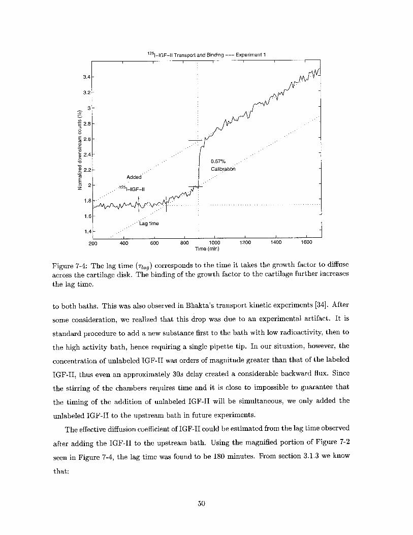
600
100n i
125i1
I I I I I I III
1251-IGF-Il Transport and Binding --- Experiment 1
3
E 2.8
E 2.6-
Z5
2.4-0-0 0.57%.
D2.2- CalibrationCO Added'
Lag time
ZI I G F -111.4-
200 400 600 800 1000 1200 1400 1600Time (min)
Figure 7-4: The lag time (Tag) corresponds to the time it takes the growth factor to diffuse
across the cartilage disk. The binding of the growth factor to the cartilage further increases
the lag time.
to both baths. This was also observed in Bhakta's transport kinetic experiments [34]. After
some consideration, we realized that this drop was due to an experimental artifact. It is
standard procedure to add a new substance first to the bath with low radioactivity, then to
the high activity bath, hence requiring a single pipette tip. In our situation, however, the
concentration of unlabeled IGF-II was orders of magnitude greater than that of the labeled
IGF-II, thus even an approximately 30s delay created a considerable backward flux. Since
the stirring of the chambers requires time and it is close to impossible to guarantee that
the timing of the addition of unlabeled IGF-II will be simultaneous, we only added the
unlabeled IGF-II to the upstream bath in future experiments.
The effective diffusion coefficient of IGF-II could be estimated from the lag time observed
after adding the IGF-II to the upstream bath. Using the magnified portion of Figure 7-2
seen in Figure 7-4, the lag time was found to be 180 minutes. From section 3.1.3 we know
that:
50
I I I I I -- I
3.4-[
3.2-
Tia 627.1)6Def f
therefore,62 (340pm) 2 1min 2
Deff = - m 6 = 1.78 - 10 - c (7.2)6Tlag 6 - 180min 60s s
This estimation of Deff, however, is not the diffusion coefficient of IGF-I, but an effec-
tive diffusion coefficient that is considerably less due to binding. It is, therefore, expected
that the actual diffusion coefficient calculated from the measured flux of the growth factor
will be greater than the coefficient found from the lag time.
The diffusion coefficient found by using the Stokes-Einstein Relation in Section 3 was
found to be an order of magnitude greater. This is mostly due to the binding of the growth
factor to the tissue during transport. The time lag for IGF-II found in my experiments also
corresponded well with the lag time measured for IGF-I in the experiments done by Garcia
et al. [33]
The diffusion coefficient of radiolabeled materials through the cartilage disk can be found
assuming that the potential drop across the cartilage is negligible. The diffusion coefficient
in this case is simply the ratio of the change in downstream activity and the upstream
concentration:
I' 6 a % 340pm _26 y cm 2 (73D = -- : r 6- = 2.17.- 10-5 0 4/t = 2.66 - 10- .M (17.3)
Vc cU 7 cm 23 2.77 'Y 10
The diffusion coefficient calculated this way, however, gives us the combined diffusion
of the labeled IGF-II and the free labeled iodide. Since in our results we found that the
dissociation after 3100 minutes is already significant (20%), and we know that the diffusion
coefficient of a small iodide will be much greater than the diffusion coefficient of IGF-II, we
must account for the free label flux in order to find the IGF-II diffusion coefficient and the
number of binding sites within the tissue.
Assuming that at time t=0 we did not have any free label, and at time t=3100min we
had 20% of the labels dissociated from the IGF-II, we can calculate the time constant of
dissociation assuming an exponential dissociation function:
3100min 4.
T - - - 1.389- 10 min. (7.4)In(1 - 0.2)
If we are trying to find the diffusion coefficient of IGF-II, it is enough to look at the linear
51
portion of our graph after calibration between 902 and 1827 minutes. The governing equa-
tions during this portion, assuming that only 1251- and 1 25 I-IGF-II contribute significantly
to the total radioactive flux, are the following:
F2, = F* - FI (7.5)
where r2* is the labeled IGF-II flux, IF, is the total radioactive flux, and 17I is the labeled
iodide flux.
Using the definition of flux we know that
F* = - (7.6)A At
since the flux is constant according to our results. Using Fick's First Law, we also know
that
r, = Dc- cd ~DIC D (7.7)
andcO ,e-t/Tr
IF2,= D2 2(7.8)
assuming that the diffusion of 125 I-IGF-II is steady and the downstream concentration of
125 I-IGF-II is negligible.
Combining the above equations we can find the diffusion coefficient of IGF-II has a
negative value, which is impossible. Hence, our assumptions are not valid! Some of the
assumptions such as the downstream concentration of 1251- being negligible, and the cal-
culated value of r being accurate, are incorrect. Since our results for D 2 are very sensitive
to r, an inaccurate value can easily give a nonsensical value for D. The solution to this
problem is to prevent the dissociation of labeled IGF-II by cooling down its environment.
7.2 Experiment 2.
The second IGF-II transport kinetic experiment was based on the first one with a few
alterations. Even though this experiment still had some complications, the results were
noteworthy, and quantitative calculations could be carried out based on the results.
52
7.2.1 Method
The experimental procedures remained the same as for Experiment 1, except for a few
minor changes:
1. Unlabeled growth factors were added only to the upstream chamber. This prevented
uncontrollable backwards flux due to inevitable delays between the equilibration of
the two chambers.
2. Instead of using a circulating cooling system, the chamber setup was moved to a
refrigerator at 9'C for the length of the experiment. This was necessary to maintain
the integrity of the labeled IGF-II and reduce the dissociation of the labels from the
growth factor.
3. No IGF-I was added during the experiment since according to both Experiment 1 and
the experiments done by Bhakta (Section 4.4), IGF-I has no effect on the transport
kinetics of IGF-II across the cartilage.
4. I tested the case of adding 0.1nM unlabeled IGF-II to see whether competition for
binding sites occurred at lower concentrations. 0.1nM was chosen also because it is
on the same order of magnitude as the labeled IGF-II concentration of the upstream
bath.
5. The calibration was done after the experiment had finished running to minimize the
amount of radioactive material that was found in the downstream chamber at the end
of the run.
6. The thickness of the disks was 330pm instead of 340pm.
7. I also added more proteinase inhibitors to ensure that minimal tissue degradation
occurred over the course of the experiment. These inhibitors were 5mM benzamidine
HCl and 1mM PMSF.
7.2.2 Results
The preparatory chromatographic results of the 12 5 1-IGF-II can be seen in Figure 7-5. The
result indicate that the labeled IGF-II wad excellent quality, containing less than 2% of
labeled iodide and even less large aggregates. We used fractions 47-62 for the experiments.
53
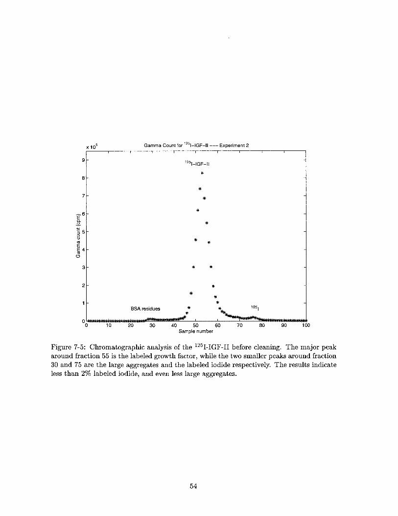
Gamma Count for 1251-G-II --- Experiment 2
125 11-GF-11
*
*
*
*
**
* *
**
BSA residues. . . . . . . ..
10 20 30 40 50Sample number
*
* 1251
60 70 80 90 100
Figure 7-5: Chromatographic analysis of the 12 5 1-IGF-II before cleaning. The major peakaround fraction 55 is the labeled growth factor, while the two smaller peaks around fraction30 and 75 are the large aggregates and the labeled iodide respectively. The results indicateless than 2% labeled iodide, and even less large aggregates.
54
x 105
9
8
7
6
5
4
0
0CU)
EECs0
3-
2-
0O
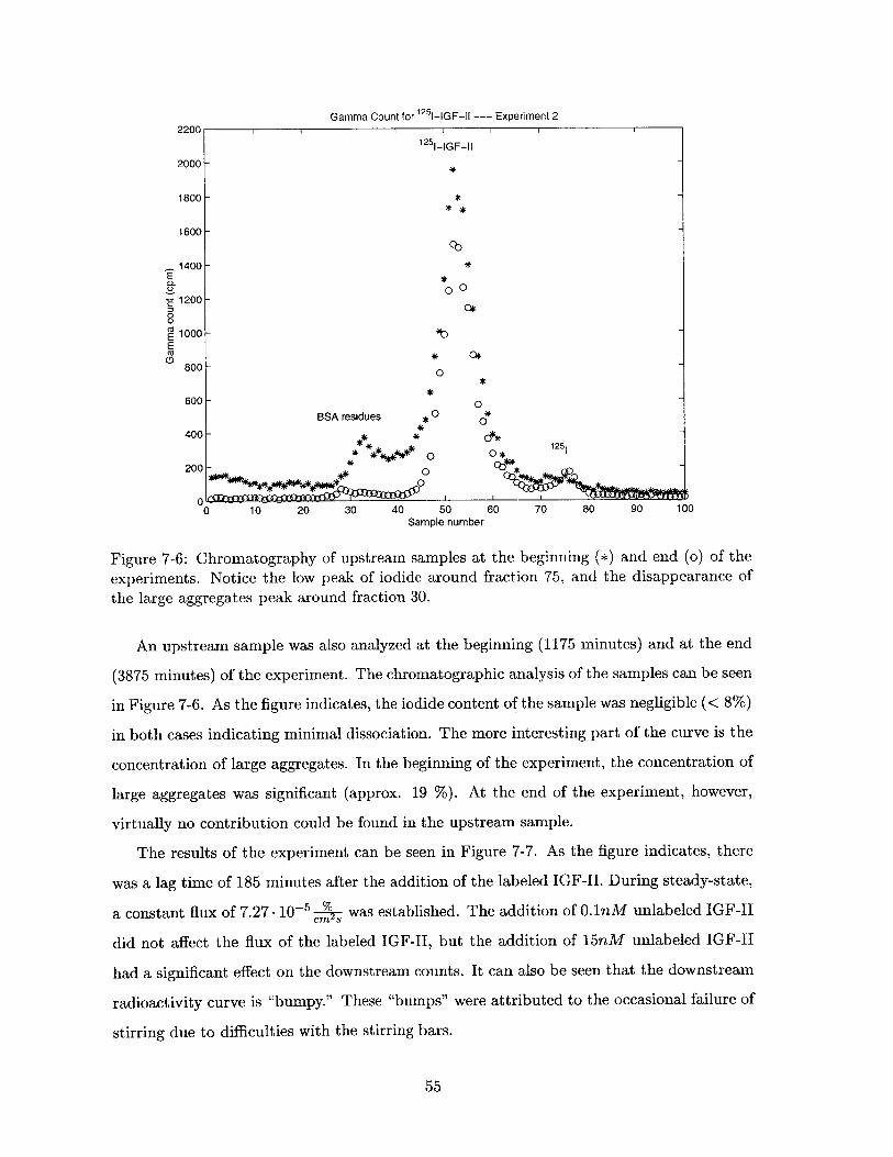
Gamma Count for 125 -IGF-l1 -- Experiment 22200 11 1 1 1 1
12 51-GF-11
2000-
1800- *
1600-
1400- *E
COL~100 -E c*E 1200 -D00
E1000-E
800-*
600- 0BSA residues 00 *
400- -125
200-_ 0
0 10 20 30 40 50 60 70 80 90 100Sample number
Figure 7-6: Chromatography of upstream samples at the beginning (*) and end (o) of the
experiments. Notice the low peak of iodide around fraction 75, and the disappearance of
the large aggregates peak around fraction 30.
An upstream sample was also analyzed at the beginning (1175 minutes) and at the end
(3875 minutes) of the experiment. The chromatographic analysis of the samples can be seen
in Figure 7-6. As the figure indicates, the iodide content of the sample was negligible (< 8%)
in both cases indicating minimal dissociation. The more interesting part of the curve is the
concentration of large aggregates. In the beginning of the experiment, the concentration of
large aggregates was significant (approx. 19 %). At the end of the experiment, however,
virtually no contribution could be found in the upstream sample.
The results of the experiment can be seen in Figure 7-7. As the figure indicates, there
was a lag time of 185 minutes after the addition of the labeled IGF-II. During steady-state,
a constant flux of 7.27 - 10-5% was established. The addition of 0.1nM unlabeled IGF-II
did not affect the flux of the labeled IGF-II, but the addition of 15nM unlabeled IGF-II
had a significant effect on the downstream counts. It can also be seen that the downstream
radioactivity curve is "bumpy." These "bumps" were attributed to the occasional failure of
stirring due to difficulties with the stirring bars.
55
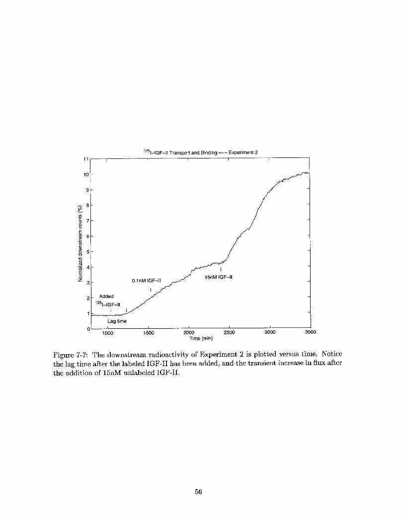
1251-IGF-I1 Transport and Binding --- Experiment 211
10
9
00
ECa
E
0z0
7
6
5
4
3
2
1
01000 1500 2000 2500 3000
Time (min)3500
Figure 7-7: The downstream radioactivity of Experiment 2 is plotted versus time. Notice
the lag time after the labeled IGF-II has been added, and the transient increase in flux after
the addition of 15nM unlabeled IGF-II.
56
The difference between the expected downstream count at 3500 minutes due to simple
flux of the labeled IGF-1I and the actual value should have corresponded to the previously
cartilage-bound labeled IGF-II that was displaced by the unlabeled IGF-II. This difference
was found to be 1.87%.
7.2.3 Discussion
The lag time found in this experiment was 185 minutes, which agrees well with the 180
minutes found in the previous experiment. Using this new lag time to calculate the effective
diffusion coefficient we find that
62 (330pm) 2 1min _4 cm2Def 1.64 -10- . (7.9)6 Trag - 6 - 185min 60s s
This value is within 8% of the previously found diffusion coefficient.
A steady-state flux of 7.27 - 10- was measured, which is 3.35 times greater than
the 2.17- 10- % found in the previous experiment. It is still unclear why the steady-state
flux was 3.35 times higher than in the previous experiment. Some of the possibilities are
that the stirring might have been more efficient, hence decreasing the stagnant layers on
the cartilage disks and increasing flux. Another possibility is that a leak might have been
present, but the presence of the lag time makes this possibility rather unlikely.
The "bumps" in the graph can be attributed to the lack of stirring, since the checkups on
the system (and the fixing of the stirring bars) corresponded well with the reestablishment
of the original slope. The lack of stirring in these situations created a thick stagnant layer
of solutions on both sides of the cartilage, forcing the labeled IGF-II to diffuse across this
layer as well as the cartilage. Since diffusion is much slower than convection, this resulted
in a significant decrease of the labeled IGF-II flux.
The results show that the addition of 0.1nM of unlabeled IGF-II had no noticeable effect
on the transport kinetics of labeled IGF-II. On the other hand, we can see that 15nM of
unlabeled IGF-II created a significant jump in the downstream count, indicating possible
competitive binding to the tissue. These results correlate well with Bhakta et al.'s [19]
finding that competition occurs only at concentrations greater than 10nM.
The lack of stirring before the 15nM unlabeled IGF-II had been added might also explain
the surprisingly high jump in the downstream count. If a stagnant layer had been established
57
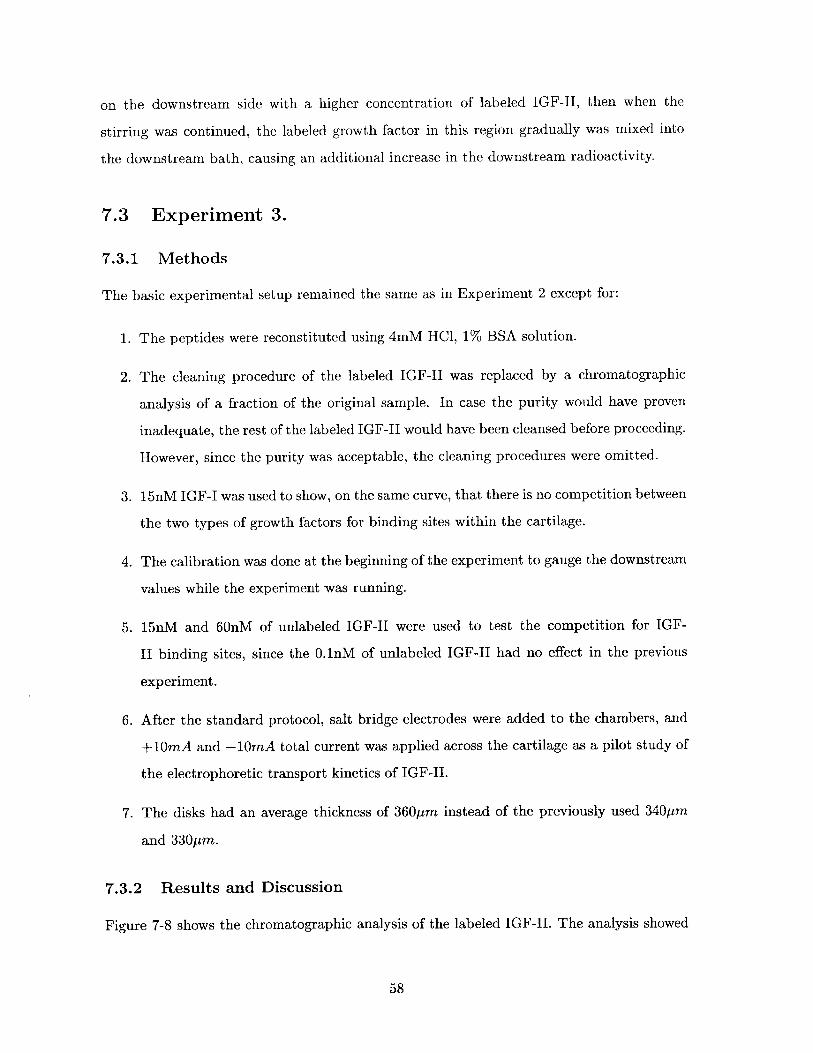
on the downstream side with a higher concentration of labeled IGF-II, then when the
stirring was continued, the labeled growth factor in this region gradually was mixed into
the downstream bath, causing an additional increase in the downstream radioactivity.
7.3 Experiment 3.
7.3.1 Methods
The basic experimental setup remained the same as in Experiment 2 except for:
1. The peptides were reconstituted using 4mM HCl, 1% BSA solution.
2. The cleaning procedure of the labeled IGF-II was replaced by a chromatographic
analysis of a fraction of the original sample. In case the purity would have proven
inadequate, the rest of the labeled IGF-II would have been cleansed before proceeding.
However, since the purity was acceptable, the cleaning procedures were omitted.
3. 15nM IGF-I was used to show, on the same curve, that there is no competition between
the two types of growth factors for binding sites within the cartilage.
4. The calibration was done at the beginning of the experiment to gauge the downstream
values while the experiment was running.
5. 15nM and 60nM of unlabeled IGF-II were used to test the competition for IGF-
II binding sites, since the .1nM of unlabeled IGF-II had no effect in the previous
experiment.
6. After the standard protocol, salt bridge electrodes were added to the chambers, and
+10mA and -10mA total current was applied across the cartilage as a pilot study of
the electrophoretic transport kinetics of IGF-II.
7. The disks had an average thickness of 360pm instead of the previously used 340pm
and 330pm.
7.3.2 Results and Discussion
Figure 7-8 shows the chromatographic analysis of the labeled IGF-II. The analysis showed
58
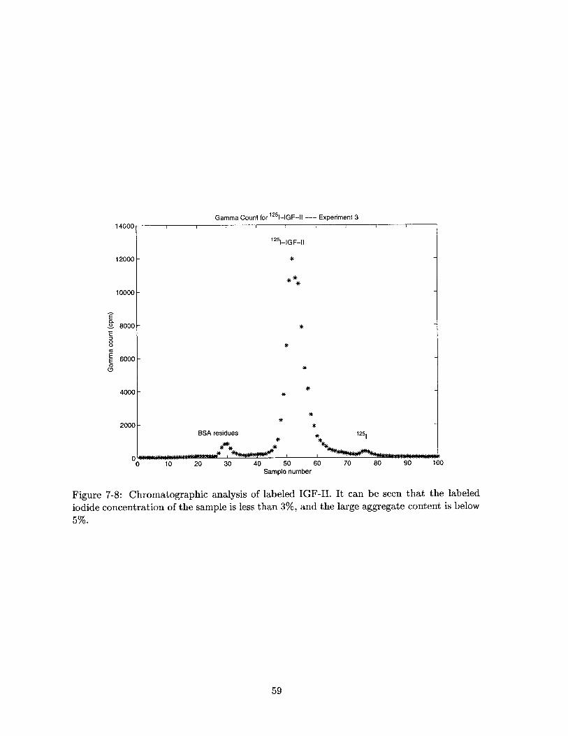
Gamma Count for 1251-IGF-Il --- Experiment 3
BSA residues
1251-lGF-II
*
*
*
*
**
*
*125
10 20 30 40 50Sample number
60 70 80 90 100
Figure 7-8: Chromatographic analysis of labeled IGF-II. It can be seen that the labeled
iodide concentration of the sample is less than 3%, and the large aggregate content is below
5%.
59
14000
0.
0
EE0
8000-
6000-
4000-
2000-
0
--
12000 -
10000 -
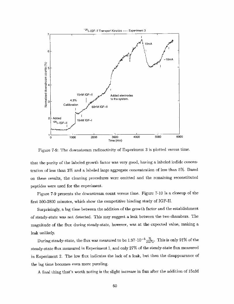
1251-IGF-II Transport Kinetics --- Experiment 37
6-
-1OmA
Z3-
00
E
Calb aina0 M I F l
11)
14-
0_0
to the system.
0 CallibrationZ 1 6OnM IGF-11
2 Added f1251_ GF-11 l5nM IGF-I
0 1000 2000 3000 4000 5000 6000Time (min)
Figure 7-9: The downstream radioactivity of Experiment 3 is plotted versus time.
that the purity of the labeled growth factor was very good, having a labeled iodide concen-
tration of less than 3% and a labeled large aggregate concentration of less than 5%. Based
on these results, the cleaning procedures were omitted and the remaining reconstituted
peptides were used for the experiment.
Figure 7-9 presents the downstream count versus time. Figure 7-10 is a closeup of the
first 500-2800 minutes, which show the competitive binding study of IGF-II.
Surprisingly, a lag time between the addition of the growth factor and the establishment
of steady-state was not detected. This may suggest a leak between the two chambers. The
magnitude of the flux during steady-state, however, was at the expected value, making a
leak unlikely.
During steady-state, the flux was measured to be 1.97- 10--5c. This is only 91% of the
steady-state flux measured in Experiment 1, and only 27% of the steady-state flux measured
in Experiment 2. The low flux indicates the lack of a leak, but then the disappearance of
the lag time becomes even more puzzling.
A final thing that's worth noting is the slight increase in flux after the addition of 15nM
60
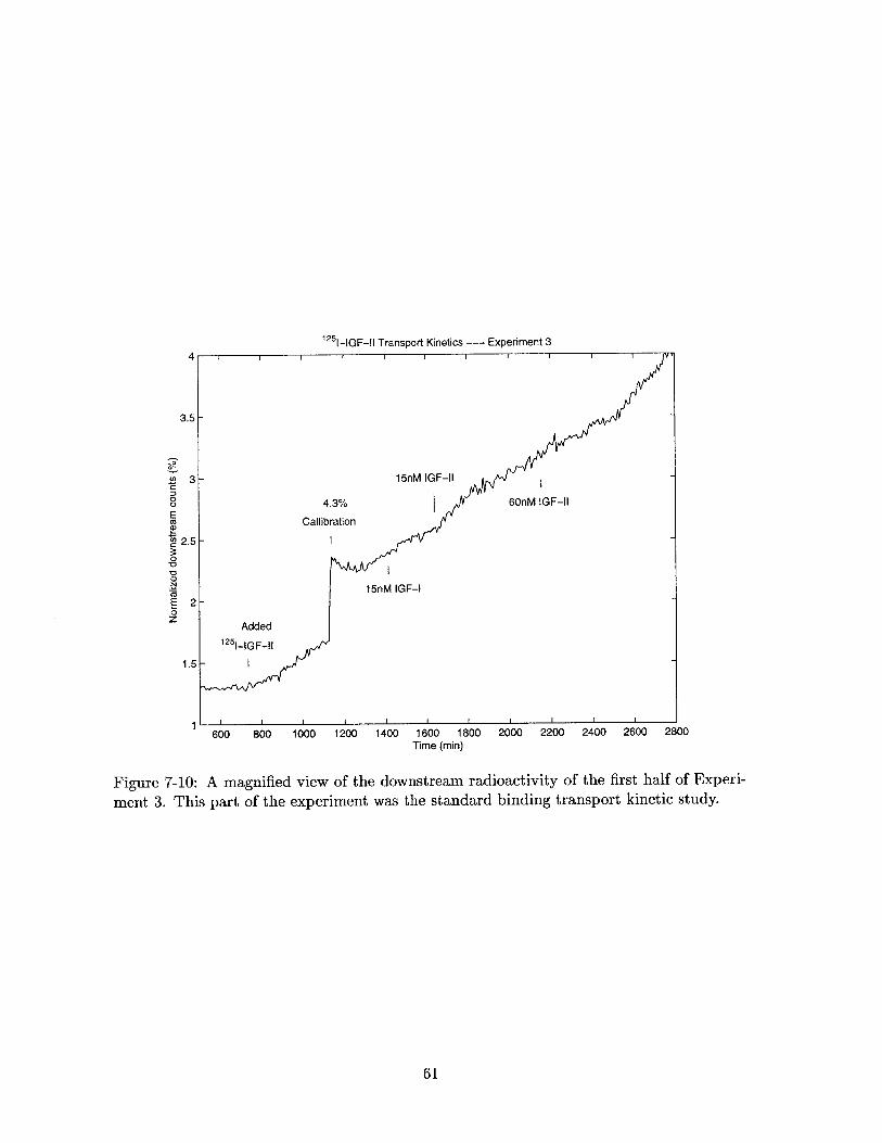
1251-IGF-II Transport Kinetics --- Experiment 34
3.5
~30
ECO
S2.50
N
0z
1.5
600 800 1000 1200 1400 1600 1800Time (min)
2000 2200 2400 2600 2800
Figure 7-10: A magnified view of the downstream radioactivity of the first half of Experi-
ment 3. This part of the experiment was the standard binding transport kinetic study.
61
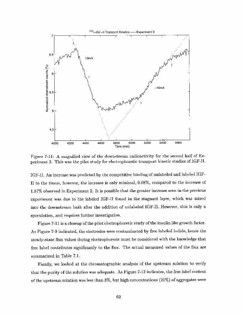
1251-GF-11 Transport Kinetics -- Experiment 37
6.5-1OmA
0
E
-1OmA
05.5-
.N
0z 5
4.5-
4000 4200 4400 4600 4800 5000 5200 5400 5600Time (min)
Figure 7-11: A magnified view of the downstream radioactivity for the second half of Ex-
periment 3. This was the pilot study for electrophoretic transport kinetic studies of IGF-II.
IGF-II. An increase was predicted by the competitive binding of unlabeled and labeled IGF-
II to the tissue, however, the increase is only minimal, 0.08%, compared to the increase of
1.87% observed in Experiment 2. It is possible that the greater increase seen in the previous
experiment was due to the labeled IGF-II found in the stagnant layer, which was mixed
into the downstream bath after the addition of unlabeled IGF-II. However, this is only a
speculation, and requires further investigation.
Figure 7-11 is a closeup of the pilot electrophoretic study of the insulin like growth factor.
As Figure 7-9 indicated, the electrodes were contaminated by free labeled iodide, hence the
steady-state flux values during electrophoresis must be considered with the knowledge that
free label contributes significantly to the flux. The actual measured values of the flux are
summarized in Table 7.1.
Finally, we looked at the chromatographic analysis of the upstream solution to verify
that the purity of the solution was adequate. As Figure 7-12 indicates, the free label content
of the upstream solution was less than 3%, but high concentrations (21%) of aggregates were
62
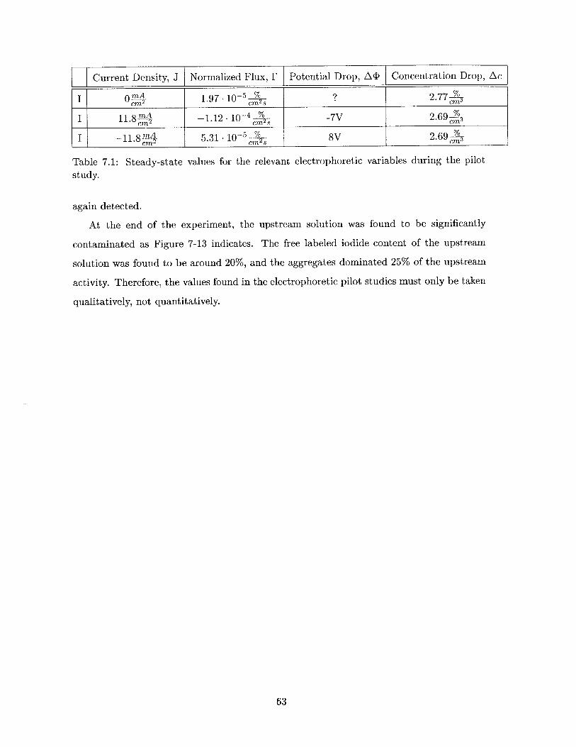
Current Density, J Normalized Flux, F Potential Drop, A<D Concentration Drop, Ac
I mA 1.97- 10-'5 ? 2.775_M2 cm2 s cm 3
I 11.8 -1.12 .10-4l -7V 2.69 '
I -11.84 5.31 - 10-5 8V 2.69
Table 7.1: Steady-state values for the relevant electrophoretic variables during the pilot
study.
again detected.
At the end of the experiment, the upstream solution was found to be significantly
contaminated as Figure 7-13 indicates. The free labeled iodide content of the upstream
solution was found to be around 20%, and the aggregates dominated 25% of the upstream
activity. Therefore, the values found in the electrophoretic pilot studies must only be taken
qualitatively, not quantitatively.
63
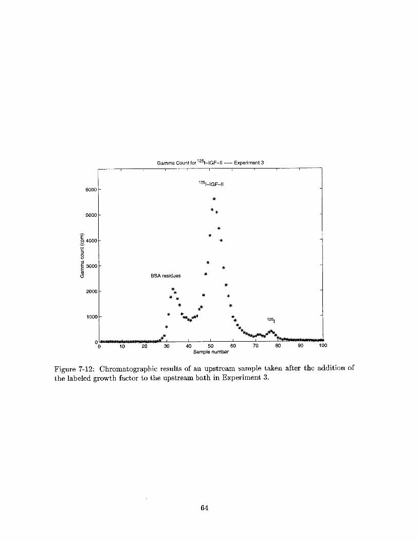
Gamma Count for 125 1-IGF-l1 --- Experiment 31~ I I I
125 1-GF-il
*
*
*
*
*
*
*g 125
0 10 20 30 40 50Sample number
BSA residues
**
*
M lk|^\\^\M*
60 70 80 90 100
Figure 7-12: Chromatographic results of an upstream sample taken after the addition of
the labeled growth factor to the upstream bath in Experiment 3.
64
0.4000 -
0
E 3000 -E(0
0
6000 -
5000 -
2000 -
1000 - -se
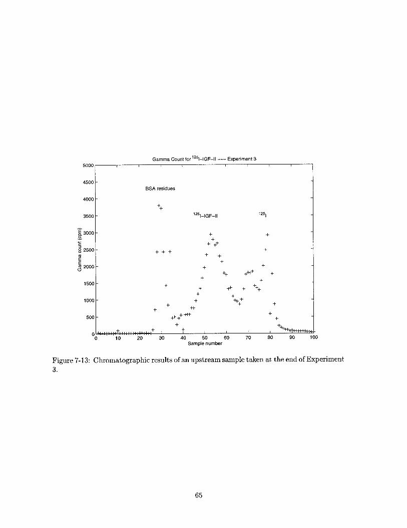
Gamma Count for 1251-IGF-Il --- Experiment 35000-
4500 -BSA residues
4000-
3500 - 125 I-IGF-II 125 ..
E 3000 -+
02500- +CU+ +
EE +cu 2000 - +
0+ ++ ++I++ +
1500 +
+ F + +1000- + ++
500- ++++H + +
+ =60 10 20 30 40 50 60 70 80 90 100
Sample number
Figure 7-13: Chromatographic results of an upstream sample taken at the end of Experiment
3.
65
Chapter 8
Conclusions
8.1 Summary
Articular cartilage provides cushioning and distributes load over articulating joint surfaces.
Healthy cartilage is extremely resilient to shear and compressive stress, but its homeostasis
is easily disrupted due to its low cell count and perfusion rate. The transport of macro-
molecules, therefore, plays a rate limiting role in tissue regeneration after injury. The goal
of this thesis was to study the transport of IGF-II, a regulatory solute, in the tissue.
In this study we have shown that even though the size of IGF-II is on the order of the
average intermolecular spacing within the tissue, transport and binding do occur. We have
successfully found the characteristic time scale of IGF-II transport and binding. Further-
more, we have presented proof of the reversible nature of IGF-II binding and showed that
at physiological concentrations IGF-I is not capable of competing with IGF-II for binding
sites.
8.2 Future Work
The work that is described in this thesis in only the beginning of a whole series of transport
kinetic experiments. In order to fully describe the behavior of macromolecular transport
and binding within cartilage, the following experiments will be performed in the near future:
e Testing the stirring apparatus of the current setup. This can be done by testing
labeled iodide transport across tissue in the absence and presence of stirring.
66
" Testing the competition between IGF-II with IGF-I for binding sites by running the
transport kinetic studies using labeled IGF-I, and adding graded amounts of IGF-II
to the upstream bath.
" Testing the effect of an applied electric field on the transport of IGF-I and IGF-II.
" Measuring the open-circuit voltage during future transport experiments.
" Testing the effect of tissue degradation and altered tissue charge on transport by using
degrading enzymes or altering the pH.
The above experiments should provide sufficient information to quantify the transport
kinetic and binding properties of IGF-I and IGF-II, and hence complete this study.
67
Bibliography
[1] B. Y. Lin. Characterization of the properties of cartilage in the hartley guinea pig spon-
taneous osteoarthritis model. Master's project, Massachusetts Institute of Technology,
Electrical Engineering and Computer Science Department, June 1997.
[2] J. J. Zhu. Transport studies of chondroitin sulfate disaccharide through articular car-
tilage. Master's project, Massachusetts Institute of Technology, Electrical Engineering
and Computer Science Department, June 1997.
[3] A. Maroudas. Physical Chemistry of Articular Cartilage and the Intervertebral Disc. In
Joints and Synovial Fluid, pp. 239-291. (ed. L. Sokoloff), volume 2. Academic Press,
New York. 1980.
[4] R. A. Stockwell and G. Meachim. The Chondrocytes. Grune & Stratton, New York,
NY, 1972.
[5] A. M. Garcia. Mechanisms of Macromolecular Transport Through Articular Carti-
lage: Relevance to Loading. PhD dissertation, Massachusetts Institute of Technology,
Department of Harvard-M.I.T. Division of Health Sciences and Technology, June 1996.
[6] T. M. Quinn, A. A. Maung, A. J. Grodzinsky, E. B. Hunziker, and J. K. Sandy. Physical
and biological regulation of proteoglycan turnover around chondrocytes in cartilage
explants: Implications for tissue degradation and repair. unpulished document, 1999.
[7] T. I. Morales. Transforming growth factor-3 and insulin-like growth factor-1 restore
proteoglycan metabolism of bovine articular cartilage after depletion by retinoic acid.
Archives of Biochemistry and Biophysics, 315(1):001-009, Nov. 1994.
[8] H. Muir. The chondrocyte, architect of cartilage. BioEssays, 17(12):1039-1048, 1995.
68
[9] W. K. Manning and W. M. Bonner. Isolation and culture of chondrocytes from human
adult articular cartilage. Arthritis Rheum., 10(235), 1967.
[10] A. L. Lehninger, D. L. Nelson, and M. M. Cox. Principles of Biochemistry. Worth
Publishers, New York, NY, second edition, 1993.
[11] J. F. Bateman, S. R. Lamande, and J. A. M. Ramshaw. Collagen Superfamily in
Extracellular Matrix, volume 2. Overseas Publishers Association, Amsterdam, The
Netherlands, first edition, 1996.
[12] D. R. Eyre, A. Apon, J.-J. Wu, L. H. Ericsson, and K. A. Walsh. Collagen type ix:
evidence for covalent linkages to type ii collagen in cartilage. Federation of European
Biochemical Societies Letters, 220(2):337-341, June 1987.
[13] R. N. Wight, D. K. Heinegard, and V. C. Hascall. Cell Biology of Extracellular Matrix.
Plenum Press, New York, NY, second edition, 1991.
[14] D. Heinegard and A. Oldberg. Structure and biology of cartilage and bone matrix
noncollagenous macromolecules. FASEB J., 3:2042-2051, 1989.
[15] R. Schneiderman, E. Snir, 0. Popper, J. Hiss, H. Stein, and A. Maroudas. Insulin-
like growth factor-1 and its complexes in normal human articular caritlage: Studies of
partition and diffusion. Archives of Biochemistry and Biophysics, 324(1):159-172, Dec.
1995.
[16] T. L. Blundell, S. Bedarkar, and R. E. Hunbel. Tertiary structures, receptor binding,
and antigenicity of insulin-like growth factors. Federation Proc., 42:2592-2597, 1983.
[17] R. Schneiderman, N. Rosenberg, J. Hiss, P. Lee, F. Liu, R. L. Hintz, and A. Maroudas.
Concentration and size distribution of insulin-like growth factor-1 in human normal and
osteoarthritic synovial fluid and cartilage. Archives of Biochemistry and Biophysics,
324(1):173-188, Dec. 1995.
[18] T. I. Morales. The role and content of endogenous insulin-like growth factor-binding
proteins in bovine articular cartilage. Archives of Biochemistry and Biophysics,
343(2):164-172, July 1997.
69
[19] N. R. Bhakta, T. I. Morales, E. H. Frank, and A. J. Grodzinsky. Insulin-like growth fac-
tor (igf) bind specifically to endogenous igf binding proteins in adult articular cartilage.
ORS abtract, Feb. 1999.
[20] A. Fick. On liquid diffusion. Philos. Mag., 10:30-39, 1855.
[21] T. F. Weiss. Cellular Biophysics, volume 2. MIT Press, Cambridge, MA, first edition,
1996.
[22] A. Einstein. Investigations on the Theory of the Brownian Movement, R. Furthe and
A. D. Cowper, eds. Dover, New York, NY, 1956.
[23] W. M. Deen. Analysis of Transport Phenomena. Oxford University Press, New York,
NY, first edition, 1998.
[24] G. G. Stokes. On the effect of the internal friction of fluids on the motion of pendulums.
Trans. Camb. Phil. Soc., 9:6-106, 1851.
[25] A. J. Grodzinsky. Fields, forces and flows in biological tissues and membranes. Course
notes for 6.561J at MIT, 1998.
[26] I. Binderman, D. Somjen, Z. Shimshoni, J. Levy, H. Fischler, and R. Korenstein.
Stimulation of skeletal-derived cell cultures by different electric field intensities is cell-
specific. Biochim Biophys Acta, 844:273-279, 1985.
[27] J. P. Elliott, R. L. Smith, and C. A. Block. Time-varying magnetic fields; effects of
orientiation on chondrocyte proliferation. Journal of Orthopaedic Research, 6:259-264,
1988.
[28] R. L.-Y. Sah, Y.-J. Kim, J.-Y. Doong, A. J. Grodzinsky, A. H. K. Plaas, and J. D.
Sandy. Biosynthetic response of cartilage explants to dynamic compression. Journal
of Orthopaedic Research, 7:619-636, 1989.
[29] A. J. Grodzinsky, Y.-J. Kim, M. D. Buschmann, A. M. Garcia, T. M. Quinn, and
E. B. Hunziker. Response of the chondrocyte to mechanical stimuli. Osteoarthritis.
Ed: Brandt, Doherty, Lohmander.
70
[30] L. Lippiello, D. Chakkalakal, and J. F. Connolly. Pulsing direct current-induced repair
of articular cartilage in rabbit osteochondral defects. Journal of Orthopaedic Research,
8:266-275, 1990.
[31] H. Liu, J. Abbott, and J. A. Bee. Pulsed electromagnetic fields influence hyaline
cartilage extracellular matrix composition without affecting molecular structure. Os-
teoarthritis and Cartilage, 4:63-76, 1996.
[32] L. A. MacGinitie, Y. A. Gluzband, and A. J. Grodzinsky. Electrical field stimulation
can increase protein synthesis in articular cartilage explants. Journal of Orthopaedic
Research, 12:151-160, 1994.
[33] A. M. Garcia, E. H. Frank, S. B. Trippel, and A. J. Grodzinsky. Igf-1 transport in
cartilage: Effects of binding and intratissue fluid flow. ORS abtract, Feb. 1997.
[34] N. R. Bhakta. Transport kinetics of insulin-like growth factor-2. unpublished data,
1997.
[35] I. N. Levine. Physical Chemistry. McGraw-Hill Book Company, New York, NY, third
edition, 1988.
71