transport and main roads specifications mrts94 road lighting/media/busind/techstdpubs/specifications...
TRANSCRIPT
Technical Specification Transport and Main Roads Specifications MRTS94 Road Lighting July 2017

Transport and Main Roads Specifications, July 2017
Copyright
http://creativecommons.org/licenses/by/3.0/au/
© State of Queensland (Department of Transport and Main Roads) 2017
Feedback: Please send your feedback regarding this document to: [email protected]
Transport and Main Roads Specifications, July 2017 i
Contents
1 Introduction ....................................................................................................................................1
2 Definition of terms .........................................................................................................................1
3 Referenced documents .................................................................................................................1
3.1 Standards and specifications .......................................................................................................... 1
3.2 Standard drawings .......................................................................................................................... 2
4 Quality system requirements .......................................................................................................3
4.1 Hold Points, Witness Points and Milestones .................................................................................. 3
5 Compliance with legislation .........................................................................................................4
6 Compliance with other documentation .......................................................................................4
7 Design by the contractor ..............................................................................................................4
7.1 Submission of design ...................................................................................................................... 4
7.2 Additional requirement – design of poles ....................................................................................... 4
7.3 Additional requirement – luminaires ............................................................................................... 5
7.4 Design changes during construction .............................................................................................. 5
7.5 Electricity entity ............................................................................................................................... 5
8 Material ...........................................................................................................................................5
8.1 General ........................................................................................................................................... 5
8.2 Rate 3 road lighting materials ......................................................................................................... 5 8.2.1 Road lighting poles .........................................................................................................5 8.2.2 Road lighting luminaires .................................................................................................5 8.2.3 Terminal panels ..............................................................................................................8 8.2.4 Miscellaneous materials .................................................................................................9
9 Installation, removal and/or relocation of equipment ................................................................9
9.1 Road lighting luminaires and pedestrian crossing floodlights – Rate 3 .......................................... 9
9.2 Installation of poles – Rate 3 .......................................................................................................... 9
9.3 Pole markings – Rate 3 ................................................................................................................ 10
9.4 Removal of road lighting luminaires and pedestrian crossing floodlights – Rate 3 ...................... 10
9.5 Relocation of road lighting luminaires and pedestrian crossing floodlights – Rate 3 ................... 10
9.6 Removal of poles – Rate 3 ........................................................................................................... 10
9.7 Relocation of poles – Rate 3 ......................................................................................................... 10
9.8 Wiring – Rate 3 ............................................................................................................................. 10
9.9 Earthing ......................................................................................................................................... 11 9.9.1 Earthing of ground-mounted lighting poles ................................................................. 11 9.9.2 Earthing of lighting installations on bridges and other structures ................................ 11 9.9.3 Lighting installations adjacent to railway overhead lines............................................. 12
10 Testing ......................................................................................................................................... 12
10.1 Testing procedure ......................................................................................................................... 12
10.2 Testing requirements .................................................................................................................... 12
10.3 Testing records ............................................................................................................................. 12
Transport and Main Roads Specifications, July 2017 ii
11 Luminaire warranty ..................................................................................................................... 13
11.1 General ......................................................................................................................................... 13
11.2 HID luminaires .............................................................................................................................. 13
11.3 LED luminaires.............................................................................................................................. 13
12 Packaging .................................................................................................................................... 13
13 Environmental considerations .................................................................................................. 14
14 Training ........................................................................................................................................ 14
15 Supplementary requirements .................................................................................................... 14
Attachment 1 – Technical details HID luminaire .............................................................................. 15
Attachment 2 – Technical details LED luminaire ............................................................................. 16
Attachment 3 – Luminaire performance requirements for Category “V” high pressure sodium luminaires ............................................................................................................................................. 17
Attachment 4 – Luminaire performance requirements for Category “V” LED luminaires ........... 25
Technical Specification, MRTS94 Road Lighting
Transport and Main Roads Specifications, July 2017 1
1 Introduction
This Technical Specification applies to the supply and installation of Rate 3 Road Lighting Equipment, including the requirements for the manufacture, testing and delivery of luminaires, pedestrian crossing floodlights and luminaire terminal panels.
This Technical Specification does not apply to Rate 1 or 2 Road Lighting. For Rate 1 or 2 lighting reference shall be made to the relevant electricity entity policies, standards and specifications.
This Technical Specification shall be read in conjunction with MRTS01 Introduction to Technical Specifications, MRTS50 Specific Quality System Requirements and other Technical Specifications as appropriate.
This Technical Specification forms part of the Transport and Main Roads Specifications Manual.
All Electrical Works shall comply with the requirements of the most current amendments of Electrical Safety Act 2002 and regulations and codes of practice.
2 Definition of terms
The terms used in this Technical Specification shall be as defined in Clause 2 of MRTS01 Introduction to Technical Specifications. Further definitions are defined in Table 2 and AS/NZS 3000.
Table 2 - Definition of terms
Term Definition
Act Electrical Safety Act 2002 and associated Regulations and Codes of Practice
Administrator Principal’s Representative or Superintendent as defined in Clause 14 of MRTS01 Introduction to Technical Specifications
Electricity Entity As defined in the Act
Electrical Works As defined in the Act
Licensed Electrical Contractor Holder of an Electrical Contractor License under the Act
Rate 1 Lighting Public lighting supplied, installed, owned and maintained by the electricity entity
Rate 2 Lighting Public lighting owned and maintained by the electricity entity
Rate 3 Lighting Public lighting supplied, installed, owned and maintained by Transport and Main Roads
3 Referenced documents
3.1 Standards and specifications
All equipment and material, where not otherwise specified, shall be in accordance with the appropriate Australian Standard Specifications, where such exist, and in their absence, with BSI, IEC or ISO Specifications.
Where a standard specification is quoted or implied the latest version shall be applicable, including the amendments to date.
A list of relevant Australian Standards and other related documents, referred to in this Technical Specification, is shown in Table 3.1.
Technical Specification, MRTS94 Road Lighting
Transport and Main Roads Specifications, July 2017 2
Table 3.1 - Referenced documents
Reference Title
ANSI C136.41 Roadway and Area lighting Equipment – Dimming control between an external locking photo-control and ballast or driver
AS 4068 Flat pallets for material handling
AS/NZS 1158.1.1 Lighting for roads and public spaces – Vehicular traffic (Category V) lighting – Performance and design requirements
AS/NZS 1158.2 Lighting for roads and public spaces – Computer procedures for the calculation of light technical parameters for Category V and Category P lighting
AS/NZS 1158.4 Supplementary lighting at pedestrian crossings
AS/NZS 3000 Electrical installations (known as the Australian/New Zealand Wiring Rules)
AS/NZS 60598.1 Luminaires – Part 1: General requirements and tests
AS/NZS 60598.2.3 Luminaires – Part 2.3: Particular requirements – Luminaires for Road and Street Lighting
AS/NZS 60598.2.5 Luminaires – Part 2.5: Particular requirements – Floodlights
AS/NZS CISPR 15 Limits and methods of measurement of radio disturbance characteristics of electrical lighting and similar equipment
AS/NZS ISO 9001 Quality Management Systems - requirements
CIE S 025 Test method for LED lamps, LED luminaires and LED modules
IES LM-79-08 Approved method for Electrical and Photometric measurements of Solid State lighting products
IES LM-84-14 Approved method for measuring luminous flux and colour maintenance of LED lamps, light engines and luminaires
IES TM-28-14 Projecting long-term luminous flux maintenance of LED lamps and luminaires
MRTS01 Introduction to Technical Specifications
MRTS50 Specific Quality System Requirements
MRTS97 Mounting Structures for Roadside Equipment
RPDM Road Planning and Design Manual – published by Transport and Main Roads
SA/SNZ TS 1158.6:2015 Lighting for roads and public spaces – Luminaires - Performance 3.2 Standard drawings
Table 3.2 lists the departmental Standard Drawings referenced in this Technical Specification or relevant to the design, construction, maintenance and operation of Road Lighting.
Technical Specification, MRTS94 Road Lighting
Transport and Main Roads Specifications, July 2017 3
Table 3.2 - Referenced Standard Drawings
Drawing Number Title
1323 Road Lighting – Luminaire terminal panel
1335 Road Lighting – Pedestrian crossing floodlight mounting bracket outreach mount (option 2)
1336 Road Lighting – Pedestrian crossing floodlight mounting bracket spigot mount (option 1)
1380 Road Lighting – Slip Base Pole and footing installation details for no crossfall
1381 Road Lighting – Slip base pole and footing installation details for crossfalls up to and including 1:6
1382 Road Lighting – Slip base pole and footing installation details for crossfalls greater than 1:6 up to and including 1:3
1389 Road Lighting – Slip Base Pole Male/Female Connectors Installation Details
1390 Road Lighting – Base Plate Mounted pole aerial connection wiring details
1392 Road Lighting – Base Plate Mounted pole and footing installation details for crossfalls up to and including 1:2
1393 Road Lighting – Base Plate Mounted pole and footing installation details for crossfalls greater than 1:2
1395 Road Lighting – Base Plate Mounted pole and footing in concrete median barrier installation details
1399 Road Lighting – Base Plate Mounted pole wiring details
1400 Road Lighting – Slip Base Pole Wiring Details
1406 Road Lighting – Pedestrian crossing floodlight installation and aiming
1409 Road Lighting – Luminaire headframes wiring details excluding 4 x 400 W luminaires
1410 Road Lighting – Luminaire headframes wiring details 4 x 400 W luminaires
1411 Road Lighting – Mast arm road lighting junction box (Type B)
1412 Road Lighting – Mast arm road lighting junction box (Type B) Wiring Details
1429 Road Lighting – Slip base pole and footing installation details for crossfalls greater than 1:6 up to and including 1:3 using concrete step tread
1431 Road Lighting – Base Plate Mounted pole wiring details for median barriers
1637 Road Lighting – Underpass lighting wiring details
1671 Traffic signals/Road lighting - Road lighting labels installation
1673 Traffic Signals/Road Lighting - Labels
1707 Road Lighting – Base plate mounted pole mounted on bridges wiring details
4 Quality system requirements
4.1 Hold Points, Witness Points and Milestones
General requirements for Hold Points, Witness Points and Milestones are specified in Clause 5.2 of MRTS01 Introduction to Technical Specifications.
The Hold Points, Witness Points and Milestones applicable to this Technical Specification are summarised in Table 4.1.
Technical Specification, MRTS94 Road Lighting
Transport and Main Roads Specifications, July 2017 4
Table 4.1 - Hold Points, Witness Points and Milestones
Clause Hold Point Witness Point Milestone
7.1 1. Design by the Contractor Submission of lighting design (28 days)
7.2 2. Testing of poles 1. Testing of poles and components
7.3 3. Supply of luminaires Submission of luminaire documentation (7 days)
10.1 4. Compliance testing Submission of compliance testing procedure (28 days)
10.2 2. Compliance testing of luminaires
5 Compliance with legislation
The work covered by this Specification shall comply with the requirements of the Act and subordinate legislation and AS/NZS 3000.
The Contractor shall engage a Licensed Electrical Contractor to perform the duties and functions of Electrical Works. This includes the installation of pits and conduits for power and communications cables.
6 Compliance with other documentation
For Rate 3 Road Lighting installations, this Technical Specification shall be read in conjunction with referenced documents, RPDM Volume 6: Lighting, and AS/NZS 3000.
7 Design by the contractor
7.1 Submission of design
Where road lighting design is undertaken by the Contractor, either as part of the Contract or as an alternative design, the requirements of Clause 7 shall apply.
Not less than 28 days prior to installation of luminaires and/or poles, the Contractor shall submit to the Administrator, a road lighting design which complies with the requirements of RPDM Volume 6 - Lighting. Milestone The design shall be submitted in accordance with the provisions of the relevant clauses of the Conditions of Contract and/or Supplementary Conditions of Contract governing design by the Contractor.
Construction under this Technical Specification shall not commence until expiration of the 28 day period or as otherwise provided for by the relevant design by the Contractor clauses mentioned in the second paragraph of this clause. Hold Point 1
7.2 Additional requirement – design of poles
Refer to MRTS97 Mounting Structures for Roadside Equipment for all requirements relating to road lighting pole, outreach arms, luminaire headframes and luminaire brackets. Hold Point 2 Witness Point 1
Technical Specification, MRTS94 Road Lighting
Transport and Main Roads Specifications, July 2017 5
7.3 Additional requirement – luminaires
At least seven days prior to delivery to the site, for each luminaire, supporting documentation, as detailed in Section 6 of SA/SNZ TS 1158.6 and this Technical Specification, including manufacturer’s drawings, shall be submitted to the Administrator. All photometric data provided must be supported by an independent test report from a laboratory which is endorsed by an accreditation body which is a signatory to the International Laboratory Accreditation Corporation (ILAC) through the Mutual Recognition Agreement (MRA). A current Transport and Main Roads type approval certificate for the luminaire is sufficient for supporting documentation. Milestone
The submission shall include evidence of the reliability of equipment and the performance of the proposed materials for a service life of 20 years under the system configuration and environmental conditions stated in the Drawings. Such evidence shall support the manufacturer’s stated reliability and performance, including Failure Mode and Effect Analysis. The submission shall include a list of current users of the proposed equipment, including contact names and phone numbers of personnel who can verify the stated service performance.
Luminaires shall not be delivered to the site until expiration of the seven day period. Hold Point 3
Where so stated in Clause 1 of Annexure MRTS94.1, production samples of luminaires shall be submitted to the Administrator. Samples shall be used for the purpose of providing reference against which all subsequent items are compared for compliance with this Technical Specification.
7.4 Design changes during construction
Any change to the design of any component proposed during construction shall be subject to the provisions of Clause 7. Only after all the requirements of Clause 7 have been satisfied shall such changes be incorporated in the Works.
7.5 Electricity entity
As part of the design requirement, the provision of new road lighting installations and the removal or relocation of existing road lighting luminaires shall require advice to be provided to the Electricity Entity. Such advice shall include at least a record of the location (e.g. suburb), wattage and pole number of all luminaires. A copy of such advice shall be included in the quality records.
8 Material
8.1 General
All equipment and component parts shall comply with the requirements of this Technical Specification.
8.2 Rate 3 road lighting materials
8.2.1 Road lighting poles
Refer to MRTS97 Mounting Structures for Roadside Equipment for all requirements relating to road lighting poles, outreach arms, luminaire head frames and luminaire brackets.
8.2.2 Road lighting luminaires
8.2.2.1 General
Luminaires other than pedestrian crossing floodlights shall be designed and constructed in accordance with the requirements of AS/NZS 60598.2.3 and SA/SNZ TS 1158.6. Photometric performance to AS/NZS 1158.1.1 and AS/NZS 1158.2.
Technical Specification, MRTS94 Road Lighting
Transport and Main Roads Specifications, July 2017 6
Luminaires for pedestrian crossing floodlights shall be designed and constructed to AS/NZS 60598.2.5, and shall have photometric performance to AS/NZS 1158.4.
The equipment shall be exposed to the environmental conditions detailed in Clause 1.5 of SA/SNZ TS 1158.6.
Top entry access to the control gear chamber is preferred for road lighting luminaires. Compartment covers shall comply with SA/SNZ TS 1158.6, Clause 2.7.
All luminaires shall be fitted with a Metal Oxide Varistor (MOV) type surge suppressor with a minimum energy absorption capacity of not less than 320 joules, across the active and neutral terminals to provide high voltage surge protection for the luminaire components.
Luminaires shall be design such that the stated photometric distribution of the luminaire shall be maintained throughout its life.
There shall be no electrical connections between the neutral block and the luminaire body.
Luminaires shall comply with the relevant spigot fixing sizes detailed in Clause 4.1 of AS 1798. The depth of the spigot entry shall be as specified in Table 2.2 of SA/SNZ TS 1158.6.
Luminaires shall have a mass no greater than 15 kg and a sail area no greater than 0.17 m².
The electrical interference produced by the luminaire shall not exceed the limits prescribed in AS/NZS CISPR 15.
The luminaire shall be on the Australian Energy Market Operator (AEMO) National Electricity Market Load Tables for Unmetered Loads.
8.2.2.2 High Intensity Discharge (HID) luminaires
Luminaires shall be supplied as:
a) side entry mounting dished prismatic visor and flat visor aero screen luminaires with integral control gear for use with high pressure sodium vapour (HPS) 100 W, 150 W, 250 W and 400 W clear tubular lamps
b) high mast luminaires with integral control gear designed for use with HPS 250 W and 400 W clear tubular lamps, or
c) pedestrian crossing floodlights with integral control gear designed for use with HPS 250 W and 400 W clear tubular lamps and ceramic metal halide lamps. Nominal Correlated Colour Temperature (CCT) shall be 4000 K for metal halide lamps. Metal halide lamps must be capable of running on HPS control gear.
The luminaire shall be provided with at least the following degrees of protection when tested in accordance with AS/NZS 60598.1:
a) Lamp Chamber – IP65, and
b) Control Gear Chamber – IP24.
Luminaires shall not be individually controlled by a photoelectric cell
Aeroscreen luminaires shall have a clear flat toughened glass visor.
Visors for Category V luminaires (except aeroscreen types) shall not be manufactured from glass.
Technical Specification, MRTS94 Road Lighting
Transport and Main Roads Specifications, July 2017 7
All Category V road lighting luminaires and pedestrian crossing floodlights shall be fitted with a skirted lamp holder suitable for E39/41 and E40/41 lamps.
All Category V road lighting luminaires and pedestrian crossing floodlights shall be supplied complete with appropriate lamps.
The lamps shall be packaged in separate containers to prevent breakage during transport.
Additionally, details of the method employed to ensure that the lamp holder/lamp configuration shall not move during the expected life of the luminaire, so that the lamp shall not impact the visor during normal service conditions (e.g. installations on bridges), shall be submitted.
The control gear and termination assembly shall comply with Section 2.6 of SA/SNZ TS 1158.6.
Power factor correction capacitors shall be incorporated in the luminaires to provide operation at a nominal power factor of not less than 0.85 lagging. In addition to the requirements of Clause 4.2 of SA/SNZ TS 1158.6 the capacitor shall have the following features:
a) 280 V rating
b) hermetically sealed
c) metal can housing
d) incorporate internal safety feature in event of capacitor failure, and
e) minimum 85ºC temperature rating.
The lamp ignitor shall be a timed ignitor with an internal electronic timer to automatically switch off high voltage pulses after 11 minutes of attempting to strike the lamp and shall also comply with the requirements of Clause 3.2.3 of SA/SNZ TS 1158.6.
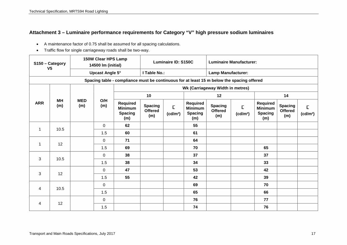
Category V road lighting luminaire performance shall be assessed against the spacing tables in Attachment 3.
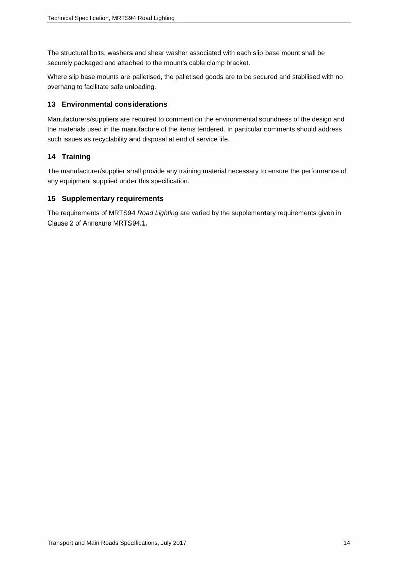
Attachment 1 for each luminaire submitted shall be provided to the Administrator.
8.2.2.3 LED luminaires
Luminaires shall be supplied as:
a) side entry mounting luminaires with integral control gear
b) pedestrian crossing floodlights with integral control gear.
The luminaire shall be provided with at least the following degrees of protection when tested in accordance with AS/NZS 60598.1:
a) LED Chamber – IP65, and
b) Control Gear Chamber – IP65 or where the LED driver unit has an IP65 rating the control gear chamber may be IP24.
The luminaire must be capable of being monitored and controlled via a wireless control and monitoring system (CMS). If only a proprietary product to the offered luminaire can be used for monitoring and control then the department shall be made aware of this at the time of tendering.
Luminaire to be fitted with a “NEMA” 7 contact pattern photocell socket complying with ANSI C136.41 and a matching shorting plug.
Technical Specification, MRTS94 Road Lighting
Transport and Main Roads Specifications, July 2017 8
Electronic control gear shall comply with SA/SNZ TS 1158.6 Clause 3.2.4 except that the power factor shall be not less than 0.9.
Manufacturer/supplier shall detail mechanism for arresting any flicker mode for individual LED units. This must take into account dimming levels of 25%, 50%, 75% as well as 100% operating power.
Nominal correlated colour temperature (CCT) shall be 4000 (K). There shall be no variation between individual LED units comprising a complete luminaire. Chromaticity tolerance shall be, CCT tolerance 3985 ± 275 K and Duv 0.0009 ± 0.0006.
Luminaires shall have a minimum colour rendering index (CRI) of not less than 70.
Lumen depreciation after 50,000 hrs, when tested in accordance with Clause 5.7 of SA/SNZ TS 1158.6 shall be ≥ L70.
No parts shall be constructed of polycarbonate unless it is UV stabilised. (Lens discolouration shall be considered a failure under warranty).
As the luminaires are made up of a number of individual LED units the manufacturer/supplier shall detail the failure mode for the luminaire and subsequent effect on performance should individual or strings of LED’s fail.
Cooling system for the LED’s shall consist of a heat sink only with no fans, pumps or liquids and shall be resistant to debris build up to maintain the heat dissipation performance.
The department’s standard lighting outreach spigot has a 5 degree upcast. The luminaire spigot entry shall have an integral system in place to allow this to be reduced to 0 degrees.
Category V road lighting luminaire performance shall be assessed against the spacing tables in Attachment 4.
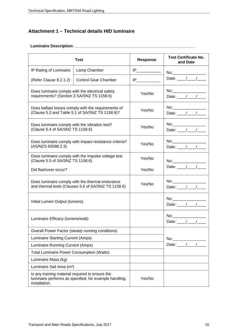
Attachment 2 for each luminaire submitted shall be provided to the Administrator.
8.2.3 Terminal panels
Terminal panels shall be as shown on Standard Drawings 1323 and 1411 as applicable to the particular pole in which they are mounted.
The terminal panel shall be suitable for operation on a 230 volt + 10% - 6%, 50 Hz ± 0.1 Hz system.
The following information shall be indelibly marked on each panel:
a) manufacturer’s/supplier’s name and identification mark, and
b) country of manufacture.
All components and ancillaries shall be securely fixed in place and the fixing devices used shall be compatible with the materials to be joined.
All steel screws, nuts and other steel parts shall be either stainless steel, galvanised, electro plated or have an equivalent protective finish.
All brass screws, nuts etc. shall be plated.
All ferrous materials shall be protected by a suitable non-corrosive finish.
Any spot welding burns and cuts shall have zinc rich paint applied to provide suitable corrosion protection.
Technical Specification, MRTS94 Road Lighting
Transport and Main Roads Specifications, July 2017 9
8.2.4 Miscellaneous materials
Nuts, screws, bolts and washers, pole markings, cable terminations, insulation tape, heat shrink tubing and all materials necessary to complete the installation of the pole shall be provided as required.
9 Installation, removal and/or relocation of equipment
9.1 Road lighting luminaires and pedestrian crossing floodlights – Rate 3
The luminaire shall be connected to the lighting circuit and mounted onto the outreach arm or, for pedestrian crossing floodlights, mounted onto the outreach arm spigot by means of a mounting bracket as shown on Standard Drawings 1335 and 1336.
Mounting may be completed before the pole is erected only if the following steps are adhered to:
a) the luminaire shall not be in contact with the ground when fixing to the outreach arm spigot
b) sufficient care shall be taken to reduce undue stress and vibration while the pole is being erected, and
c) for road lighting luminaires, the luminaire shall be fixed to the outreach arm spigot such that, when the pole is installed in its upright position, the luminaire is correctly aligned with respect to the road surface so that the luminaire is parallel with the grade of the road at its centre-line.
Cabling shall be secured clear of the luminaire ballast or other heat sources which may degrade the cable insulation.
Pedestrian crossing floodlights shall be aimed so that the maximum intensity of the luminaire coincides with the calculated aiming point as shown on Standard Drawing 1406. The aiming point shall be as detailed in the Drawings.
9.2 Installation of poles – Rate 3
Base plate mounted pole installation for crossfalls up to and including 1:2 shall be erected in accordance with Standard Drawing 1392.
Base plate mounted pole installation details for crossfalls greater than 1:2 shall be erected in accordance with Standard Drawing 1393.
Base plate mounted poles erected in concrete median barriers shall be erected in accordance with Standard Drawing 1395.
Base plate mounted poles on bridges shall be erected in accordance with the requirements of the bridge structural drawings. The requirement for a high access hatchway shall be confirmed before installation. The poles shall be oriented so that the access hatchway faces the roadway. An internally mounted stainless steel plastic coated wire shall be fitted between the terminal panel strap and the access hatchway door.
The purpose of using the stainless steel plastic coated wire is to prevent the door from accidentally falling when opened.
Slip base poles erected in locations with no cross fall shall comply with Standard Drawing 1380.
Slip base pole installation for crossfalls up to and including 1:6 shall be in accordance with Standard Drawing 1381.
Technical Specification, MRTS94 Road Lighting
Transport and Main Roads Specifications, July 2017 10
Slip base pole installation for crossfalls greater than 1:6 up to and including 1:3 shall be in accordance with either Standard Drawings 1382 or 1429.
Where the cross fall exceeds 1:3 the use of a slip base pole is not recommended.
9.3 Pole markings – Rate 3
Pole markings shall be as stated in the Drawings and comply with Standard Drawings 1671 and 1673 or, where not so stated, the minimum requirement shall be a MR3 Road Lighting Label.
9.4 Removal of road lighting luminaires and pedestrian crossing floodlights – Rate 3
Rate 3 luminaires shall be de-energised before removal. Luminaires that are removed shall be returned to the owning Regions store or other designated location. Care shall be taken in the transportation of the luminaires such that they arrive in the same condition as they were when removed and without any further damage from transportation.
Any damage that occurs due to removal or handling subsequent to removal shall be made good by the Contractor.
9.5 Relocation of road lighting luminaires and pedestrian crossing floodlights – Rate 3
Luminaires to be relocated shall be first checked for any internal or external damage including gaskets and control gear. If the fitting is damaged in any way, a report of such damage shall be provided to the Administrator.
The luminaire shall be stored under cover in a clean dry location until required to be reinstalled.
The luminaire visor and reflecting surfaces shall be cleaned prior to reinstallation.
The luminaire shall be re-installed in accordance with the requirements of this Specification.
9.6 Removal of poles – Rate 3
The pole shall be lifted from the footing and laid down carefully.
Poles that are removed shall be returned to the owning authority’s store or other designated location. They may be disassembled for transport. Care shall be taken in the transportation of the poles and outreach arms such that they arrive in a sound serviceable condition without any further damage.
Any damage that occurs due to removal or handling subsequent to removal shall be made good by the Contractor.
9.7 Relocation of poles – Rate 3
The pole shall be lifted from the footing and carefully laid down. It shall be examined for any structural damage, e.g. rust, dents. If the pole is damaged in any way, a report of such damage shall be provided to the Administrator.
Once inspected, the internal electrical components shall be removed and stored in a clean dry location. The pole shall be stored in a safe place until required to be reinstalled. It shall not be stored directly on the ground.
The pole shall be installed in accordance with the requirements of this Technical Specification.
9.8 Wiring – Rate 3
Pole wiring in base plate mounted poles, including joint use traffic signal and road lighting poles, shall comply with Standard Drawing 1399.
Technical Specification, MRTS94 Road Lighting
Transport and Main Roads Specifications, July 2017 11
Where base plate mounted poles are located in a concrete median barrier the wiring shall comply with Standard Drawing 1431.
Wiring for base plate mounted poles where power is supplied by an overhead cable shall comply with Standard Drawing 1390.
Wiring for base plate mounted poles on bridges or other structures shall comply with Standard Drawing 1707.
Wiring in slip base poles shall comply with Standard Drawing 1400.
Wiring details for an energy absorbing pole shall be supplied to the Administrator for approval.
Luminaire head-frames wiring, excluding 4 x 400 W luminaires shall comply with Standard Drawing 1409.
Luminaire head-frames wiring for 4 x 400 W luminaires shall comply with Standard Drawing 1410.
Wiring for luminaires mounted on brackets in underpasses or walls shall comply with Standard Drawing 1637.
Pole wiring in a combination traffic signal mast arm shall comply with Standard Drawing 1412.
9.9 Earthing
All metal and concrete poles shall be earthed in accordance with the requirements of AS/NZS 3000 and the relevant Standard drawings.
9.9.1 Earthing of ground-mounted lighting poles
Lighting poles shall be earthed by direct connection to the supply neutral by means of a connection having a cross sectional area of not less than 6 mm² (copper).
A separate earth stake is not required for poles that are supported by an anchor cage and footing installed in the ground, provided that all bolted connections used to attach the pole to the foundation are of low electrical resistance (e.g. not painted, bolts tight, not corroded, etc.).
Where the pole interface with ground is not of low electrical resistance, an earth stake shall be bonded to the neutral conductor.
9.9.2 Earthing of lighting installations on bridges and other structures
A separate earth conductor of minimum size equal to the cross sectional area of the supply active shall be installed with the supply cabling. The earth shall be connected to the earth point at the pole and at the earth point at the point of the circuit supply. At the point of circuit supply the earth shall also be connected to the neutral. The neutral conductor shall not be connected to earth at any pole on the bridge. For details refer to Standard Drawing 1707 and 1637.
Where a luminaire installed on a bridge is within 2.4 m of the ground or within 1.5 m reach of the public, the luminaire body shall be connected to the earthing system by a connection having a cross sectional area of not less than 6 mm² (copper).
This clause shall also apply to lighting installed on other structures.
Technical Specification, MRTS94 Road Lighting
Transport and Main Roads Specifications, July 2017 12
9.9.3 Lighting installations adjacent to railway overhead lines
Where a bridge passes over a railway overhead wiring network, the lighting equipment may have to be bonded to Queensland Rail's traction earthing system. In this case the earthing system shall be segregated from the MEN earthing system.
Advice shall be sought from Queensland Rail and the Electricity Entity for details of earthing requirements. Where segregation is required, the earth cable shall not be bonded to the neutral conductor.
10 Testing
10.1 Testing procedure
The Contractor is responsible for carrying out sufficient testing to ensure that materials and construction standards comply with the requirements of this Technical Specification and the requirements of the Act.
Testing shall be carried out following completion of the installation of all components and before commencement of commissioning. Tests shall include the mandatory tests detailed in AS/NZS 3000 and those detailed in Clause 10.2. The test methods to be used for equipment supplied and installed in accordance with this Technical Specification and the results achieved shall be as defined in the Act. The completed installation shall comply with the requirements of the Act and AS/NZS 3000.
At least 28 days prior to the commencement of tests of installed equipment, a compliance testing procedure shall be prepared and submitted to the Administrator. Milestone
Compliance testing shall not commence until expiration of the 28 day period. Hold Point 4
10.2 Testing requirements
The following compliance tests shall be carried out:
a) insulation and resistance tests
b) polarity tests
c) earth continuity tests
d) earth fault loop impedance tests – active to earth fault return path
e) compliance testing of luminaires and ancillaries. Test certificates shall be supplied in accordance with Clause 7.2. All test certificates shall be available in English; where requested, the tests shall be undertaken on each item in the presence of the Administrator. Witness Point 2, and
f) compliance testing of poles. Refer to MRTS97 Mounting Structures for Roadside Equipment.
10.3 Testing records
In addition to copies of completed test sheets, the following documents shall also be included in the quality records:
a) A completed Certificate of Test and Compliance.
b) Where a luminaire/floodlight has been removed and/or relocated, a record of the pole number, lamp type, wattage and date when the luminaire/floodlight was removed and/or relocated, and new location.
Technical Specification, MRTS94 Road Lighting
Transport and Main Roads Specifications, July 2017 13
c) Luminaire test certificates shall be current at the time of purchase and shall not be more than 10 years old. Where any significant change is made to the manufacturing process of the luminaire, which has the potential to affect the optical performance of the luminaire, new certified photometric data shall be provided to the department within three months of the date of process change.
d) Mill certificates showing compliance with Clause 2.3.1 of SA/SNZ TS 1158.6 shall be available for each batch of luminaires supplied.
e) The contractor shall detail the origin of all major components of the luminaire and where final assembly is undertaken.
f) Where existing switchboard loads are amended, calculations for the new individual circuit voltage drops based on the new current loading.
g) Where existing switchboard loads are altered, amended schedules and labelling.
h) A Record of Inspection and Tests, and
i) Accurate As-Constructed drawings.
11 Luminaire warranty
11.1 General
The warranty shall provide for either repair or replacement of the defective parts. The warranty is void if a luminaire defect has resulted from improper installation, improper handling, vandalism or vehicular accident. Delivery costs associated with repair or replacement of the luminaire under this warranty shall be borne by the manufacturer/supplier.
11.2 HID luminaires
A warranty must be provided for the full replacement of the luminaire (excluding lamp), due to any failure (see Clause 11.1), for a minimum of five years. This includes the control gear assembly.
11.3 LED luminaires
A warranty must be provided for the full replacement of the luminaire, due to any failure (see Clause 11.1), for a minimum of 10 years. This includes the LED light engine and power supply/drivers.
12 Packaging
All items shall be suitably packaged to ensure that the items are delivered undamaged giving due consideration to the methods and distance of transportation and handling.
All terminal panels shall be packed in suitable cardboard boxes, palletised and secured by use of heavy duty shrink wrap, strapping, or a combination of both, as required and shall be packed minimum 10, maximum 15 per carton.
All luminaires shall be packed in suitable cardboard boxes, palletised and secured by use of heavy duty shrink wrap, strapping, or a combination of both, as required. Where individual items weigh in excess of 20 kg, mild steel straps and metal crimp joiners shall be used. Pallets shall be in accordance with the requirements of AS 4068.
Cardboard boxes are to be cross stacked in addition to the requirements for wrapping/strapping.
Technical Specification, MRTS94 Road Lighting
Transport and Main Roads Specifications, July 2017 14
The structural bolts, washers and shear washer associated with each slip base mount shall be securely packaged and attached to the mount’s cable clamp bracket.
Where slip base mounts are palletised, the palletised goods are to be secured and stabilised with no overhang to facilitate safe unloading.
13 Environmental considerations
Manufacturers/suppliers are required to comment on the environmental soundness of the design and the materials used in the manufacture of the items tendered. In particular comments should address such issues as recyclability and disposal at end of service life.
14 Training
The manufacturer/supplier shall provide any training material necessary to ensure the performance of any equipment supplied under this specification.
15 Supplementary requirements
The requirements of MRTS94 Road Lighting are varied by the supplementary requirements given in Clause 2 of Annexure MRTS94.1.
Technical Specification, MRTS94 Road Lighting
Transport and Main Roads Specifications, July 2017 15
Attachment 1 – Technical details HID luminaire
Luminaire Description: ______________________________________________________
Test Response Test Certificate No. and Date
IP Rating of Luminaire Lamp Chamber IP___________ No:_______________ Date: ____/____/____ (Refer Clause 8.2.1.2) Control Gear Chamber IP___________
Does luminaire comply with the electrical safety requirements? (Section 3 SA/SNZ TS 1158.6) Yes/No
No:_______________ Date: ____/____/____
Does ballast losses comply with the requirements of (Clause 5.3 and Table 5.1 of SA/SNZ TS 1158.6)? Yes/No
No:_______________ Date: ____/____/____
Does luminaire comply with the vibration test? (Clause 5.4 of SA/SNZ TS 1158.6) Yes/No
No:_______________ Date: ____/____/____
Does luminaire comply with impact resistance criteria? (AS/NZS 60598.2.3) Yes/No
No:_______________ Date: ____/____/____
Does luminaire comply with the impulse voltage test (Clause 5.5 of SA/SNZ TS 1158.6) Yes/No No:_______________
Date: ____/____/____ Did flashover occur? Yes/No
Does luminaire comply with the thermal endurance and thermal tests (Clauses 5.6 of SA/SNZ TS 1158.6) Yes/No
No:_______________ Date: ____/____/____
Initial Lumen Output (lumens) No:_______________ Date: ____/____/____
Luminaire Efficacy (lumens/watt) No:_______________ Date: ____/____/____
Overall Power Factor (steady running conditions)
No:_______________ Date: ____/____/____
Luminaire Starting Current (Amps)
Luminaire Running Current (Amps)
Total Luminaire Power Consumption (Watts)
Luminaire Mass (kg)
Luminaire Sail Area (m²)
Is any training material required to ensure the luminaire performs as specified, for example handling, installation.
Yes/No
Technical Specification, MRTS94 Road Lighting
Transport and Main Roads Specifications, July 2017 16
Attachment 2 – Technical details LED luminaire
Luminaire Description:
Test Response Test Certificate No. and Date
IP Rating of Luminaire Lamp Chamber IP___________ No:_______________ Date: ____/____/____ (Refer Clause 8.2.1.3) Control Gear Chamber IP___________
Does luminaire comply with the electrical safety requirements? (Section 3 SA/SNZ TS 1158.6) Yes/No
No:_______________ Date: ____/____/____
Does ballast losses comply with the requirements of (Clause 5.3 and Table 5.1 of SA/SNZ TS 1158.6)? Yes/No
No:_______________ Date: ____/____/____
Does luminaire comply with the vibration test? (Clause 5.4 of SA/SNZ TS 1158.6) Yes/No
No:_______________ Date: ____/____/____
Does luminaire comply with impact resistance criteria? (AS/NZS 60598.2.3) Yes/No
No:_______________ Date: ____/____/____
Does luminaire comply with the impulse voltage test (Clause 5.5 of SA/SNZ TS 1158.6) Yes/No No:_______________
Date: ____/____/____ Did flashover occur? Yes/No
Does luminaire comply with the thermal endurance and thermal tests (Clauses 5.6 of SA/SNZ TS 1158.6) Yes/No
No:_______________ Date: ____/____/____
Correlated Colour Temperature (CCT) (K) ± (K)
No:_______________ Date: ____/____/____
Initial Lumen Output (lumens) No:_______________ Date: ____/____/____
Luminaire Efficacy (lumens/watt) No:_______________ Date: ____/____/____
Lumen Depreciation at 50,000 hrs No: _______________
Date: ____/____/____
Overall Power Factor (steady running conditions) No: _______________
Date: ____/____/____
Luminaire Driver Current (milliAmps)
Luminaire Running Current (Amps)
Total Luminaire Power Consumption (Watts)
Luminaire Mass(kg)
Luminaire Sail Area (m²)
Is any training material required to ensure the luminaire performs as specified, for example handling, installation, cleaning
Yes/No
Technical Specification, MRTS94 Road Lighting
Transport and Main Roads Specifications, July 2017 17
Attachment 3 – Luminaire performance requirements for Category “V” high pressure sodium luminaires
• A maintenance factor of 0.75 shall be assumed for all spacing calculations. • Traffic flow for single carriageway roads shall be two-way.
S150 – Category V5
150W Clear HPS Lamp 14500 lm (initial)
Luminaire ID: S150C Luminaire Manufacturer:
Upcast Angle 5° I Table No.: Lamp Manufacturer:
Spacing table - compliance must be continuous for at least 15 m below the spacing offered
ARR MH (m)
MED (m)
O/H (m)
Wk (Carriageway Width in metres)
10 12 14
Required Minimum Spacing
(m)
Spacing Offered
(m)
L̅ (cd/m²)
Required Minimum Spacing
(m)
Spacing Offered
(m)
L̅ (cd/m²)
Required Minimum Spacing
(m)
Spacing Offered
(m)
L̅ (cd/m²)
1 10.5 0 62 55
1.5 60 61
1 12 0 71 64
1.5 69 70 65
3 10.5 0 38 37 37
1.5 38 34 33
3 12 0 47 53 42
1.5 55 42 39
4 10.5 0 69 70
1.5 65 66
4 12 0 76 77
1.5 74 76
Technical Specification, MRTS94 Road Lighting
Transport and Main Roads Specifications, July 2017 18
S250 – Category V3
250W Clear HPS Lamp 28000 lm (initial)
Luminaire ID: S250C Luminaire Manufacturer:
Upcast Angle 5° I Table No.: Lamp Manufacturer:
Spacing table - compliance must be continuous for at least 15 m below the spacing offered
ARR MH (m)
MED (m)
O/H (m)
Wk (Carriageway Width in metres)
10 12 14
Required Minimum Spacing
(m)
Spacing Offered
(m)
L̅ (cd/m²)
Required Minimum Spacing
(m)
Spacing Offered
(m)
L̅ (cd/m²)
Required Minimum Spacing
(m)
Spacing Offered
(m)
L̅ (cd/m²)
1 10.5 0 45
1.5 57 41
1 12 0 52 48
1.5 58 52
3 10.5 0 38 38 39
1.5 36 35 34
3 12 0 42 42 42
1.5 42 42 41
4 10.5 0 66
1.5 62
4 12 0 75
1.5 73
5 10.5 3 0 73 69 61
1.5 66 70 68
5 12 3 0 75 66 59
1.5 76 74 65
Technical Specification, MRTS94 Road Lighting
Transport and Main Roads Specifications, July 2017 19
S250 – Category V3
250W Clear HPS Lamp 28000 lm (initial)
Luminaire ID: S250C Luminaire Manufacturer:
Upcast Angle 5° I Table No.: Lamp Manufacturer:
Spacing table - compliance must be continuous for at least 15 m below the spacing offered
ARR MH (m)
MED (m)
O/H (m)
Wk (Carriageway Width in metres)
10 12 14
Required Minimum Spacing
(m)
Spacing Offered
(m)
L̅ (cd/m²)
Required Minimum Spacing
(m)
Spacing Offered
(m)
L̅ (cd/m²)
Required Minimum Spacing
(m)
Spacing Offered
(m)
L̅ (cd/m²)
6 10.5 3
0
1.5 64
3 61 57
6 12 3
0 55
1.5 75 50
3 71 74
6 10.5 1 2.5 61
4 60 61
6 12 1 2.5 74 51
4 70 71 50
Technical Specification, MRTS94 Road Lighting
Transport and Main Roads Specifications, July 2017 20
S400 – Category V3
400W Clear HPS Lamp 48000 lm (initial)
Luminaire ID: S400C Luminaire Manufacturer:
Upcast Angle 5° I Table No.: Lamp Manufacturer:
Spacing table - compliance must be continuous for at least 15 m below the spacing offered
ARR MH (m)
MED (m)
O/H (m)
Wk (Carriageway Width in metres)
14 16 18 20
Required Minimum Spacing
(m)
Spacing Offered
(m)
L̅ (cd/m2)
Required Minimum Spacing
(m)
Spacing Offered
(m)
L̅ (cd/m²)
Required Minimum Spacing
(m)
Spacing Offered
(m)
L̅ (cd/m²)
Required Minimum Spacing
(m)
Spacing Offered
(m)
L̅ (cd/m²)
5 15 5
0 92 84 76 71
1.5 92 91 83 76
3 89 91 88 81
6 15 5 0.5 60
2 92
6 15 1 2.5 81
4 86 75 65
Technical Specification, MRTS94 Road Lighting
Transport and Main Roads Specifications, July 2017 21
S150 – Category V5 AEROSCREEN
150W Clear HPS Lamp 14500 lm (initial)
Luminaire ID: S150CA Luminaire Manufacturer:
Upcast Angle 5° I Table No.: Lamp Manufacturer:
Spacing table - compliance must be continuous for at least 15 m below the spacing offered
ARR MH (m)
MED (m)
O/H (m)
Wk (Carriageway Width in metres)
10 12 14
Required Minimum Spacing
(m)
Spacing Offered
(m)
L̅ (cd/m²)
Required Minimum Spacing
(m)
Spacing Offered
(m)
L̅ (cd/m²)
Required Minimum Spacing
(m)
Spacing Offered
(m)
L̅ (cd/m²)
1 10.5 0 41
1.5 47
1 12 0 55
1.5 57
3 10.5 0 35 33 30
1.5 34 32 31
3 12 0 41 39 38
1.5 41 38 37
4 10.5 0 57 57
1.5 56 57
4 12 0 66 66
1.5 64 65
Technical Specification, MRTS94 Road Lighting
Transport and Main Roads Specifications, July 2017 22
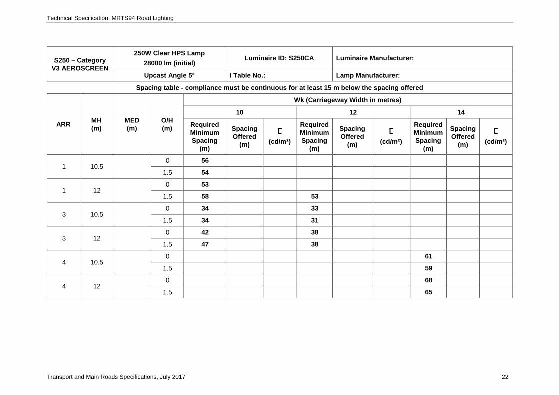
S250 – Category V3 AEROSCREEN
250W Clear HPS Lamp 28000 lm (initial)
Luminaire ID: S250CA Luminaire Manufacturer:
Upcast Angle 5° I Table No.: Lamp Manufacturer:
Spacing table - compliance must be continuous for at least 15 m below the spacing offered
ARR MH (m)
MED (m)
O/H (m)
Wk (Carriageway Width in metres)
10 12 14
Required Minimum Spacing
(m)
Spacing Offered
(m)
L̅ (cd/m²)
Required Minimum Spacing
(m)
Spacing Offered
(m)
L̅ (cd/m²)
Required Minimum Spacing
(m)
Spacing Offered
(m)
L̅ (cd/m²)
1 10.5 0 56
1.5 54
1 12 0 53
1.5 58 53
3 10.5 0 34 33
1.5 34 31
3 12 0 42 38
1.5 47 38
4 10.5 0 61
1.5 59
4 12 0 68
1.5 65
Technical Specification, MRTS94 Road Lighting
Transport and Main Roads Specifications, July 2017 23
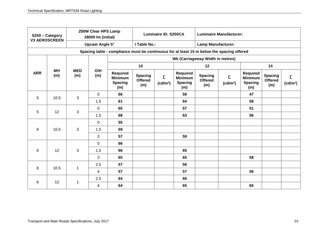
S250 – Category V3 AEROSCREEN
250W Clear HPS Lamp 28000 lm (initial)
Luminaire ID: S250CA Luminaire Manufacturer:
Upcast Angle 5° I Table No.: Lamp Manufacturer:
Spacing table - compliance must be continuous for at least 15 m below the spacing offered
ARR MH (m)
MED (m)
O/H (m)
Wk (Carriageway Width in metres)
10 12 14
Required Minimum Spacing
(m)
Spacing Offered
(m)
L̅ (cd/m²)
Required Minimum Spacing
(m)
Spacing Offered
(m)
L̅ (cd/m²)
Required Minimum Spacing
(m)
Spacing Offered
(m)
L̅ (cd/m²)
5 10.5 3 0 66 59 47
1.5 61 64 58
5 12 3 0 65 57 51
1.5 68 63 56
6 10.5 3
0 55
1.5 59
3 57 59
6 12 3
0 66
1.5 66 65
3 65 65 58
6 10.5 1 2.5 57 56
4 57 57 56
6 12 1 2.5 64 66
4 64 65 65
Technical Specification, MRTS94 Road Lighting
Transport and Main Roads Specifications, July 2017 24
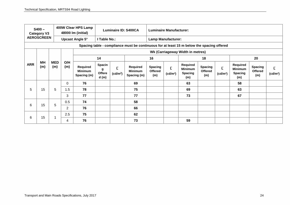
S400 – Category V3
AEROSCREEN
400W Clear HPS Lamp 48000 lm (initial)
Luminaire ID: S400CA Luminaire Manufacturer:
Upcast Angle 5° I Table No.: Lamp Manufacturer:
Spacing table - compliance must be continuous for at least 15 m below the spacing offered
ARR MH (m)
MED (m)
O/H (m)
Wk (Carriageway Width in metres)
14 16 18 20
Required Minimum
Spacing (m)
Spacing
Offered (m)
L̅ (cd/m2)
Required Minimum
Spacing (m)
Spacing Offered
(m)
L̅ (cd/m²)
Required Minimum Spacing
(m)
Spacing Offered
(m)
L̅ (cd/m²)
Required Minimum Spacing
(m)
Spacing Offered
(m)
L̅ (cd/m²)
5 15 5
0 76 69 63 58
1.5 78 75 69 63
3 77 77 73 67
6 15 5 0.5 74 58
2 76 66
6 15 1 2.5 75 62
4 76 73 59
Technical Specification, MRTS94 Road Lighting
Transport and Main Roads Specifications, July 2017 25
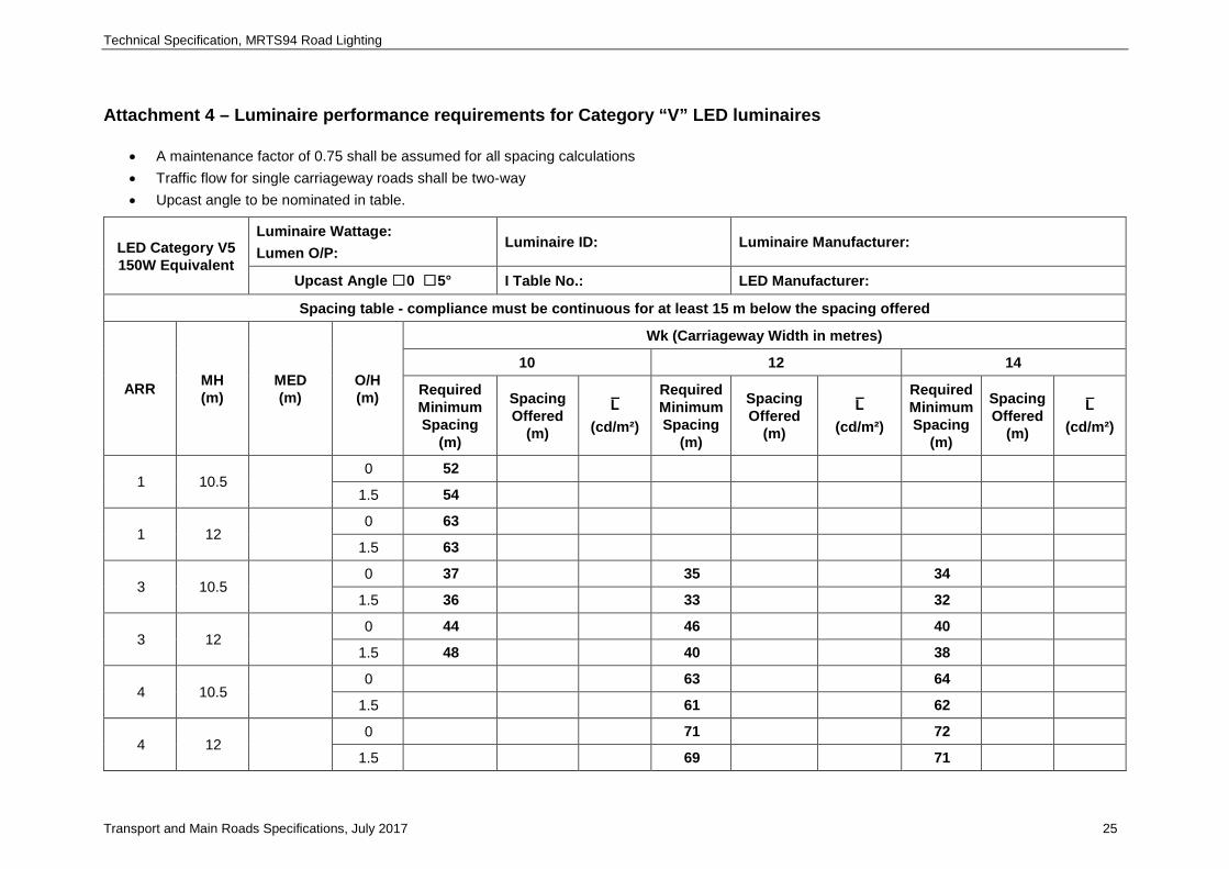
Attachment 4 – Luminaire performance requirements for Category “V” LED luminaires
• A maintenance factor of 0.75 shall be assumed for all spacing calculations • Traffic flow for single carriageway roads shall be two-way • Upcast angle to be nominated in table.
LED Category V5 150W Equivalent
Luminaire Wattage: Lumen O/P:
Luminaire ID: Luminaire Manufacturer:
Upcast Angle ☐0 ☐5° I Table No.: LED Manufacturer:
Spacing table - compliance must be continuous for at least 15 m below the spacing offered
ARR MH (m)
MED (m)
O/H (m)
Wk (Carriageway Width in metres)
10 12 14
Required Minimum Spacing
(m)
Spacing Offered
(m)
L̅ (cd/m²)
Required Minimum Spacing
(m)
Spacing Offered
(m)
L̅ (cd/m²)
Required Minimum Spacing
(m)
Spacing Offered
(m)
L̅ (cd/m²)
1 10.5 0 52
1.5 54
1 12 0 63
1.5 63
3 10.5 0 37 35 34
1.5 36 33 32
3 12 0 44 46 40
1.5 48 40 38
4 10.5 0 63 64
1.5 61 62
4 12 0 71 72
1.5 69 71
Technical Specification, MRTS94 Road Lighting
Transport and Main Roads Specifications, July 2017 26
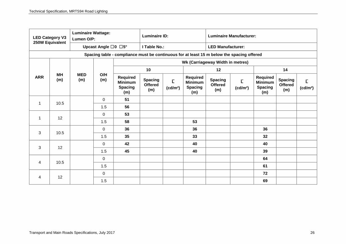
LED Category V3 250W Equivalent
Luminaire Wattage: Lumen O/P:
Luminaire ID: Luminaire Manufacturer:
Upcast Angle ☐0 ☐5° I Table No.: LED Manufacturer:
Spacing table - compliance must be continuous for at least 15 m below the spacing offered
ARR MH (m)
MED (m)
O/H (m)
Wk (Carriageway Width in metres)
10 12 14
Required Minimum Spacing
(m)
Spacing Offered
(m)
L̅ (cd/m²)
Required Minimum Spacing
(m)
Spacing Offered
(m)
L̅ (cd/m²)
Required Minimum Spacing
(m)
Spacing Offered
(m)
L̅ (cd/m²)
1 10.5 0 51
1.5 56
1 12 0 53
1.5 58 53
3 10.5 0 36 36 36
1.5 35 33 32
3 12 0 42 40 40
1.5 45 40 39
4 10.5 0 64
1.5 61
4 12 0 72
1.5 69
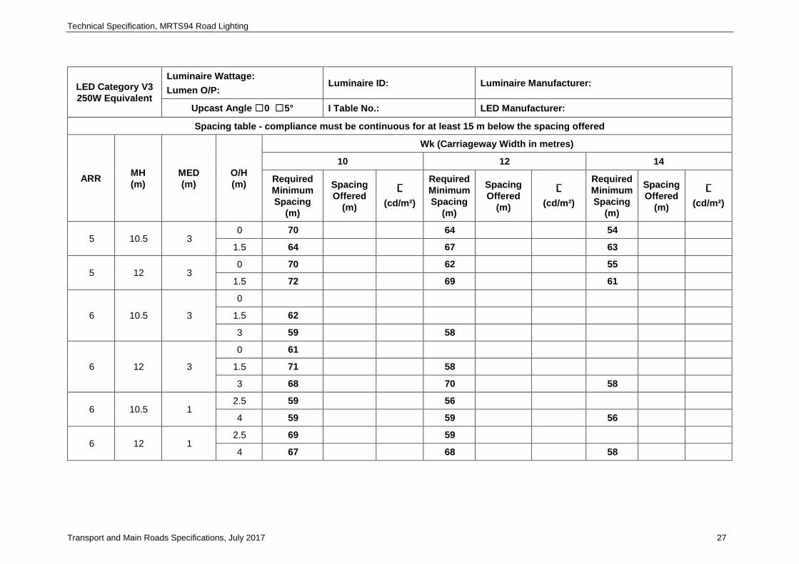
Technical Specification, MRTS94 Road Lighting
Transport and Main Roads Specifications, July 2017 27
LED Category V3 250W Equivalent
Luminaire Wattage: Lumen O/P:
Luminaire ID: Luminaire Manufacturer:
Upcast Angle ☐0 ☐5° I Table No.: LED Manufacturer:
Spacing table - compliance must be continuous for at least 15 m below the spacing offered
ARR MH (m)
MED (m)
O/H (m)
Wk (Carriageway Width in metres)
10 12 14
Required Minimum Spacing
(m)
Spacing Offered
(m)
L̅ (cd/m²)
Required Minimum Spacing
(m)
Spacing Offered
(m)
L̅ (cd/m²)
Required Minimum Spacing
(m)
Spacing Offered
(m)
L̅ (cd/m²)
5 10.5 3 0 70 64 54
1.5 64 67 63
5 12 3 0 70 62 55
1.5 72 69 61
6 10.5 3
0
1.5 62
3 59 58
6 12 3
0 61
1.5 71 58
3 68 70 58
6 10.5 1 2.5 59 56
4 59 59 56
6 12 1 2.5 69 59
4 67 68 58
Technical Specification, MRTS94 Road Lighting
Transport and Main Roads Specifications, July 2017 28
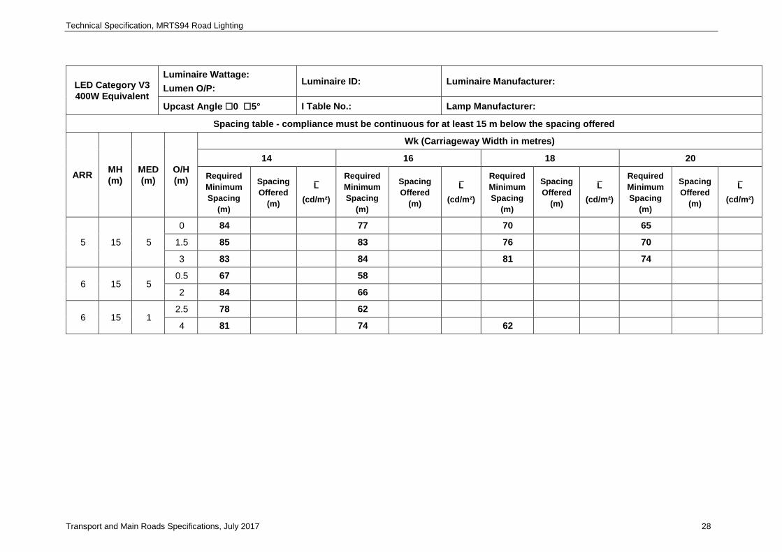
LED Category V3 400W Equivalent
Luminaire Wattage: Lumen O/P:
Luminaire ID: Luminaire Manufacturer:
Upcast Angle ☐0 ☐5° I Table No.: Lamp Manufacturer:
Spacing table - compliance must be continuous for at least 15 m below the spacing offered
ARR MH (m)
MED (m)
O/H (m)
Wk (Carriageway Width in metres)
14 16 18 20
Required Minimum Spacing
(m)
Spacing Offered
(m)
L̅ (cd/m²)
Required Minimum Spacing
(m)
Spacing Offered
(m)
L̅ (cd/m²)
Required Minimum Spacing
(m)
Spacing Offered
(m)
L̅ (cd/m²)
Required Minimum Spacing
(m)
Spacing Offered
(m)
L̅ (cd/m²)
5 15 5
0 84 77 70 65
1.5 85 83 76 70
3 83 84 81 74
6 15 5 0.5 67 58
2 84 66
6 15 1 2.5 78 62
4 81 74 62