transport guidance forklift, 6000-lb, variable reach
TRANSCRIPT

TM 55-3930-660-14
TECHNICAL MANUAL
TRANSPORT GUIDANCEFORKLIFT, 6000-LB, VARIABLE
REACH, ROUGH-TERRAIN(NSN 3930-01-158-0849)
(ARMY MODEL MHE-269)
Approved for public release; distribution is unlimited
HEADQUARTERS, DEPARTMENT OF THE ARMY
JULY 1991

TM 55-3930-660-14
TECHNICAL MANUAL
No. 55-3930-660-14
ChapterSection
ChapterSection
ChapterSection
ChapterSection
ChapterSection
1.I.
II.
III.
2.I.
II.
3.I.
II.
4.I.
II.
5.I.
II.
HEADQUARTERSDEPARTMENT OF THE ARMYWashington, DC, 31 July 1991
Approved for Public Release: Distribution is Unlimited
TRANSPORT GUIDANCEFORKLIFT, 6,000-LB, VARIABLE REACH,
ROUGH-TERRAIN, MODEL 6000M(NSN 3930-01-158-0849)(ARMY MODEL MHE-269)
INTRODUCTIONGENERALPurpose and Scope . . . . . . . . . . . . . . . . . . . . . . . . . . . . . . . . . . . . . . . . . . . . . . . . . . . . . . . . . . . . . . . . . . . . . .Related Publications . . . . . . . . . . . . . . . . . . . . . . . . . . . . . . . . . . . . . . . . . . . . . . . . . . . . . . . . . . . . . . . . . . . .User Comments . . . . . . . . . . . . . . . . . . . . . . . . . . . . . . . . . . . . . . . . . . . . . . . . . . . . . . . . . . . . . . . . . . . . . . . .Definitions . . . . . . . . . . . . . . . . . . . . . . . . . . . . . . . . . . . . . . . . . . . . . . . . . . . . . . . . . . . . . . . . . . . . . . . . . .Warnings, Cautions, and Notes . . . . . . . . . . . . . . . . . . . . . . . . . . . . . . . . . . . . . . . . . . . . . . . . . . . . . . . . . .SAFETYGeneral . . . . . . . . . . . . . . . . . . . . . . . . . . . . . . . . . . . . . . . . . . . . . . . . . . . . . . . . . . . . . . . . . . . . . . . . . . . . . . . .Hazardous Material Consideration . . . . . . . . . . . . . . . . . . . . . . . . . . . . . . . . . . . . . . . . . . . . . . . . . . . . . .EQUIPMENT DESCRIPTIONGeneral . . . . . . . . . . . . . . . . . . . . . . . . . . . . . . . . . . . . . . . . . . . . . . . . . . . . . . . . . . . . . . . . . . . . . . . . . . . . . . . .Technical Data . . . . . . . . . . . . . . . . . . . . . . . . . . . . . . . . . . . . . . . . . . . . . . . . . . . . . . . . . . . . . . . . . . . . . . . . .Reduced Conjuration . . . . . . . . . . . . . . . . . . . . . . . . . . . . . . . . . . . . . . . . . . . . . . . . . . . . . . . . . . . . . . . . . .HIGHWAY TRANSPORTGENERALGeneral . . . . . . . . . . . . . . . . . . . . . . . . . . . . . . . . . . . . . . . . . . . . . . . . . . . . . . . . . . . . . . . . . . . . . . . . . . . . . . . .Self-Delivery . . . . . . . . . . . . . . . . . . . . . . . . . . . . . . . . . . . . . . . . . . . . . . . . . . . . . . . . . . . . . . . . . . . . . . . . . . .MOTOR VEHICLE TRANSPORTPrime Mover Selection . . . . . . . . . . . . . . . . . . . . . . . . . . . . . . . . . . . . . . . . . . . . . . . . . . . . . . . . . . . . . . . . .Preparation . . . . . . . . . . . . . . . . . . . . . . . . . . . . . . . . . . . . . . . . . . . . . . . . . . . . . . . . . . . . . . . . . . . . . . . . . . . .Loading Procedures . . . . . . . . . . . . . . . . . . . . . . . . . . . . . . . . . . . . . . . . . . . . . . . . . . . . . . . . . . . . . . . . . . . . .RAIL TRANSPORTGENERALGeneral . . . . . . . . . . . . . . . . . . . . . . . . . . . . . . . . . . . . . . . . . . . . . . . . . . . . . . . . . . . . . . . . . . . . . . . . . . . . . . . .RAIL LOADINGRailcar Selection . . . . . . . . . . . . . . . . . . . . . . . . . . . . . . . . . . . . . . . . . . . . . . . . . . . . . . . . . . . . . . . . . . . . . . . .Preparation . . . . . . . . . . . . . . . . . . . . . . . . . . . . . . . . . . . . . . . . . . . . . . . . . . . . . . . . . . . . . . . . . . . . . . . . . . . .Loading Procedures . . . . . . . . . . . . . . . . . . . . . . . . . . . . . . . . . . . . . . . . . . . . . . . . . . . . . . . . . . . . . . . . . . . . .MARINE TRANSPORTGENERALGeneral . . . . . . . . . . . . . . . . . . . . . . . . . . . . . . . . . . . . . . . . . . . . . . . . . . . . . . . . . . . . . . . . . . . . . . . . . . . . . . . .SHIP LOADINGPreparation . . . . . . . . . . . . . . . . .. . . . . . . . . . . . . . . . . . . . . . . . . . . . . . . . . . . . . . . . . . . . . . . . . . . . . . . . . .Loading Procedures . . . . . . . . . . . . . . . . . . . . . . . . . . . . . . . . . . . . . . . . . . . . . . . . . . . . . . . . . . . . . . . . . . . . .Lifting Operations . . . . . . . . . . . . . . . . . . . . . . . . . . . . . . . . . . . . . . . . . . . . . . . . . . . . . . . . . . . . . . . . .AIR TRANSPORTGENERALGeneral . . . . . . . . . . . . . . . . . . . . . . . . . . . . . . . . . . . . . . . . . . . . . . . . . . . . . . . . . . . . . . . . . . . . . . . . . . . . . . . .Safety . . . . . . . . . . . . . . . . . . . . . . . . . . . . . . . . . . . . . . . . . . . . . . . . . . . . . . . . . . . . . . . . . . . . . . . . . . . . . . . . . .Hazardous Material . . . . . . . . . . . . . . . . . . . . . . . . . . . . . . . . . . . . . . . . . . . . . . . . . . . . . . . . . . . . . . . . . . . . .AIR TRANSPORTUSAF Cargo Aircraft . . . . . . . . . . . . . . . . . . . . . . . . . . . . . . . . . . . . . . . . . . . . . . . . . . . . . . . . . . . . . . . . . . .Civil Reserve Air Fleet (CRAF) . . . . . . . . . . . . . . . . . . . . . . . . . . . . . . . . . . . . . . . . . . . . . . . . . . . . . . . . . .Preparation . . . . . . . . . . . . . . . . . . . . . . . . . . . . . . . . . . . . . . . . . . . . . . . . . . . . . . . . . . . . . . . . . . . . . . . . . . .
Paragraph
1-11-21-31-41-5
1-61-7
1-81-91-10
2-12-2
2-32-42-5
3-1
3-23-33-4
4-1
4-24-34-4
5-15-25-3
5-45-55-6
Page
1-11-11-11-1?-?
1-11-2
1-21-21-2
2-12-1
2-12-12-1
3-1
3-13-13-1
4-1
4-14-14-2
5-15-15-1
5-15-15-1
i

TM 55-3930-660-14
Appendix A. References . . . . . . . . . . . . . . . . . . . . . . . . . . . . . . . . . . . . . . . . . . . . . . . . . . . . . . . . . . . . . . . . . . . . . . . . . . . . . . . . . . . . . . . . . .B. Load Restraint Factors . . . . . . . . . . . . . . . . . . . . . . . . . . . . . . . . . . . . . . . . . . . . . . . . . . . . . . . . . . . . . . . . . . . . . . . . . . . . . .C. Estimating Tiedowns . . . . . . . . . . . . . . . . . . . . . . . . . . .. . . . . . . . . . . . . . . . . . . . . . . . . . . . . . . . . . . . . . . . . . . . . . . . . . . . .
PageA-1B-1C-1
ii

TM 55-3930-660-14
CHAPTER 1
INTRODUCTION
Section I. GENERAL1-1. Purpose and ScopeThis manual is for transportation officers and otherpersonnel responsible for safe transport of the6,000-pound-capacity, variable reach, rough-terrainforklift (6K VRRTFL). It provides data for planningand executing movement of the forklift worldwide.Included are the physical characteristics of theforklift, safety precautions, technical data on trans-port modes, and lifting and tiedown procedures.
The major dimensions and weights given in thismanual are in US customary and equivalent SI(metric) units. Approximate values appear in pa-rentheses following the customary-unit value.
Transport modes are presented in chapter 2,“Highway Transport”; chapter 3, “Rail Trans-port”; chapter 4, “Marine Transport”; and chapter5, “Air Transport.”
1-2. Related Publications
Additional information on transport procedurescan be found in:
FM 55-65, Strategic Deployment by SurfaceTransportation.
TB 9-2300-281-35, Standards for OverseasShipment or Domestic Issue of Special PurposeVehicles.
TM 38-250/AFR 71-4, Preparation of HazardousMaterials for Military Air Shipment.
1-3. User Comments
Please send comments and recommendations forimproving this manual. Send them by letter, onDA Form 2028, or on a marked copy of a page orpages of the manual to Commander, MTMC Trans-portation Engineering Agency, ATTN: MTTE-TR,PO Box 6276, Newport News, VA 23606-0276.
1-4. Definitions
a. Technical terms that may be helpful whileusing this manual include:
(1) Axle Limits. A load limit set by highwayofficials or designers of ship decks and aircraft asthe maximum axle (or group of axles) weight thatcan be supported.
(2) Center of Gravity (CG). The balance pointof a suspended item. The VRRTFL counterweightis used to shift the CG to the rear. CG location isindicated by. . .
(3) Curb Weight (CW). Total weight of opera-ble 6K VRRTFL including fuel, all system fluids,and on-vehicle basic issue items (BII). CW does notinclude crew weight, which in this case is lessthan 1 percent of the gross vehicle weight.
(4) Gross Vehicle Weight (GVW) CW pluspayload. For transport purposes, a forklift has nopayload. Therefore, the GVW equals the CW.
(5) Safe Working Load (SWL). The SWL is themaximum recommended load that should be ex-erted on an item. SWL is also referred to as“working load,” “working load limit,” and “re-sultant safe working load.” Such rated load valuesare for in-line pull.
(6) Loading Restraint Factors (LRF). The LRFgiven (app B) for the surface and air modes areconsidered to be the "G" factors that can beexpected in military transport.
b. Warnings, Cautions, and Notes. Throughoutthis manual, warnings, cautions, and notes empha-size important or critical information.
***WARNING***Instructions that must be followed to pre-vent serious injury to or death of person-nel.
**CAUTION**Instructions that must be followed toavoid health hazards, or to prevent equip-ment damage.
*NOTE*An operating procedure that should re-ceive special attention.
Section II. SAFETY
1-6. General posure to normal transportation environments,Even though the 6K VRRTFL has no special several general safety considerations and precau-hazardous or dangerous characteristics during ex- tions are important.
1-1

TM 55-3930-660-14
a. Check the entire vehicleitems are properly secured.
b. Have fire extinguisherswhen operating the forklift.
c. Make sure only qualifiedthe forklift.
to be sure loose g. Do not drive the forklift on public highwayswithout appropriate safety equipment.
readily available h. Adhere to all local, State, Federal, and/orhost-nation safety laws and regulations applying –
personnel operate to commercial carriers.
d. Never permit riders, this is a one-person 1-7. Hazardous Materialmachine. Considerations
e. Do not leave the forklift unattended when theengine is running. The basic 6K VRRTFL does not contain hazardous
f. Do not allow the forklift to exceed 3 miles per material. Regulations or transportation procedureshour during loading and unloading operations covering diesel-fuel-powered vehicles will apply.
Section III. EQUIPMENT DESCRIPTION
1-8. GeneralThe 6K VRRTFL is used in support of ammunitionand quartermaster units. It can load and unloadpalletized material from the ground or fromtrailer-mounted ISO/MILVAN containers. The6,000-pound rated load (24-inch load center) is at areach of up to 15 feet. At the maximum reach of23.5 feet, the lift capacity is 4,000 pounds.
This forklift has a special lifting tool for handlingmultiple launcher rocket system (MLRS) pods.
The operator position has built-in rollover protec-tive structure (ROPS) and falling objects protectivestructure (FOPS).
The 6K VRRTFL has a six-cylinder, turbochargeddiesel engine rated at 160 horsepower. The hy-draulically powered steering is operable in threemodes: two-wheel, four-wheel, and crab. Both ax-les are full-time, all-wheel drive. The front axle isequipped with limited slip differential.
More information is available in the 6K VRRTFLOperator’s Manual, TM 10-3930-660-10.
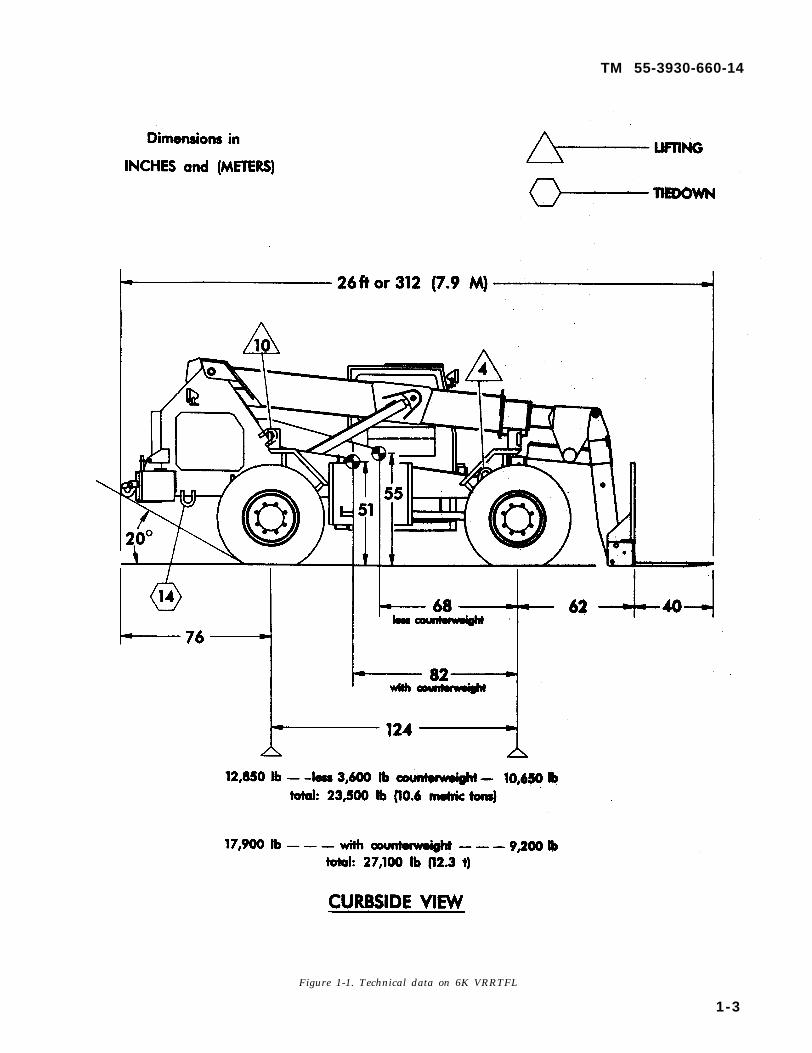
1-9. Technical DataThe following forklift characteristics and dataapply to the specific model with NSN 3930-01-158-0849. Changes in the model or NSN mayalter the data and guidance as presented in thismanual.
Line item number T48944(LIN) . . . . . . . . . . . . . . .
Gross vehicle weight 27,100 lb (12 290(GVW) . . . . . . . . . . . . . . kg)
Length:Operational . . . . . . . . . 312 in. (7.9 m)Without forks . . . . . . . 272 in. (6.9 m)
Width . . . . . . . . . . . . . . . . 102 in. (2.59 m)
Height . . . . . . . . . . . . . . .Floor area:
Operational . . . . . . . . .Without forks . . . . . . .
Volume:Operational . . . . . . . . .Without forks . . . . . . .
Turning radius (four-wheel steering):Curb level . . . . . . . . . .Entire vehicle . . . . . . .
Turning lane width . . .Tires:
Size . . . . . . . . . . . . . . . .Pressure:
Front . . . . . . . . . . . . .Rear . . . . . . . . . . . . . .
Ground pressure (at27,100 pounds GVW):Front wheel . . . . . . . . .
Gear wheel . . . . . . . . . .
101 in. (2.57 m)
220 ft2 (20 m2)190 ft2 (18 m2)
1,860 fts (52 m3)1,620 ft3 (46 m3)
15 ft (4.5 m)18 ft (5.5 m)10 ft (3 m)
17.5 x 25 L2
45 psi (310 KPa)40 psi (280 KPa)
36 lb/in.2 (2.5kg/cm2)30 lb/in.2 (2.1kg/cm2)
1-10. Reduced Configuration
There are no recommended ways to reduce theVRRTFL physical dimensions for transport. A costsaving is obtainable by reducing deck space oroverall volume needed to transport an item. Withmost forklift trucks, configuration reduction usu-ally involves removing the forklift tines and secur-ing them to the vehicle. Because of the amount ofdisassembly required, this is not advisable withthe VRRTFL.
1-2
TM 55-3930-660-14
Figure 1-1. Technical data on 6K VRRTFL
1-3

TM 55-3930-660-14
Figure 1-2. Lifting and tiedown provisions.
1 - 4
TM 55-3930-660-14
CHAPTER 2
HIGHWAY TRANSPORT
Section I. GENERAL
2-1 . Genera l
The 6K VRRTFL is highway transportable with aminimum of restrictions. However, because of its102-inch width, the forklift exceeds the maximumlegal limit of 96 inches for most States’ noninter-state highways. Permit requirements will varydepending on local regulations and conditions, butin general the shipper must:
a. Submit DD Form 1266 to the installationtransportation officer (ITO) 2 weeks before theplanned movement.
b. Be aware that travel may be restricted todaylight hours on normal workdays.
c. Be prepared to use “wide load” signs, amberlights, and escorts.
d. Determine if blanket permits are availablefor specific prime movers, such as a heavy-equipment transporter.
2-2. Self-DeliveryWith a maximum road speed of about 23 mph, the6K VRRTFL can move over highways for shortdistances under its own power. With the powertrain disconnected, it can be towed. See the 6KVRRTFL Operator’s Manual for towing proce-dures.
Section II. MOTOR VEHICLE TRANSPORT
2-3. Prime Mover SelectionThe physical size and weight of the 6K VRRTFLallow highway transport of the forklift by a vari-ety of vehicles. In selecting a transporter, theproposed route and local availability of wide loadpermits must be considered. Table 2-1 presents acomparison of military semitrailers.
Table 2-1. Evaluation of Prime Movers
LoadSemi- Rating
trailers (tons) Comments
M747 HET 60 Much too large.M870 Lowbed 40 Larger than needed, but us-
able.M872 Flatbed 34 Not well suited. Larger than
needed, but usable. Deckheight is 58 in.
M172A1 Lowbed 25 Best. Deck is 115 in. wide and40 in. high.
M871 Flatbed 22.5 Usable. Deck is 96 in. wide x55 in. high. Slight overhang of3 in. per side.
M127A2C Stake 12 Not well suited. Deck heightis 57 in. VRRTFLcounterweight must beremoved and shippedseparately.
M345 Flatbed 10 Payload too small.
When properly loaded on an M172A1 or M871, the6K VRRTFL will not overload the transporter orexceed axle limits in most geographic areas.
2-4. Preparat ionReparation for highway transport includes:
a. Filling fuel tank (or defueling) to one-quarterof its capacity.
b. Removing all trash and mud from theVRRTFL.
c. Ensuring the MLRS pod lifting tool is prop-erly positioned in its storage location on themachine.
d. Checking for fluid leaks and repairing anydefects.
e. Securing battery.f. Ensuring the VRRTFL is in good mechanical
order, with usable tiedowns, operating engine,brakes, and proper tire pressure.
g. Disconnecting the ether canister used for coldengine starting.
h. If required, removing the 3,600-pound coun-terweight to reduce the total weight of the forklift(see Operator’s Manual).
2-5. Loading Proceduresa. Material. Table 2-2 shows the bill of materi-
als for blocking and tiedown on a flatbed trailer.
2-1

TM 55-3930-660-14
Table 2-2. Bill of Materials for Transport by Semitrailer
Item Quantity Description
Chain 8 Chain assemblies, 3/8-in. by10-ft high-test welded steel,8,250-pound safe working load(16,500-pound breakingstrength); equipped withmatching grabhooks NSN4010-00-803-8858
Load binders 8 Heavyduty, double grabhook,Type 4, 3/8- to 1/2-in. (26,000-pound breaking strength) NSN3990-01-213-1746
*NOTE*
Chain assemblies and load binders arebasic issue items (BII) for the M172trailer.Load binders are generally marked withan ultimate breaking strength rating. De-pending on manufacturer, breakingstrength is about three times the safeworking load.Chain is generally rated by proof testload, or about two times the safe workingload.
b. Loading. To place the forklift in the tiedownposition on the semitrailer, use a crane of ade-
quate capacity (see para 4-4 for lifting guidance),or drive the forklift onto a semitrailer if a suitableramp is available. Position the forklift so itsweight is distributed relatively equal over thetractor and trailer axles. Set the parking brake.Place the transmission in neutral. Lower the forksto rest on trailer deck.
c. Tiedown. See figure 2–1 and table 2-3 forinstructions on restraining the forklift againstforces encountered at normal speeds and operat-ing conditions. Wheel blocking of the VRRTFL isnot required. The highway loading restraint fac-tors (LRF) used in figure 2-1 are listed inappendix B.
Table 2-3. Tiedown Procedures for Securing VRRTFL to aSemitrailer (Fig 2-1)
Item Procedure
Chains/load Properly rated chains and load binders mustbinders (8 be available for tiedown. Install at indicatedrequired) locations as shown in figure 2-1.
Wheel blocking is not required.
*NOTE*All military trucks and trailers areequipped with basic issue item (BII) loadbinders and chain.
2-2

para 2-5
Table 2-3
TM 55-3930-660-14
Figure 2-1. Tiedown of 6K VRRTFL on a flatbed semitrailer.
2-3


TM 55-3930-660-14
CHAPTER 3
RAIL TRANSPORT
Section I. GENERAL
3-1. General loading MTMCTEA Pamphlet 55–19, Tiedown
The 6K VRRTFL is transportable on most general-Handbook for Rail Movements.)
purpose, standard deck-height flatcars. The railcarmay have a wood or steel deck and standard orcushioned-draft couplers. It must have suitabletiedown points, such as stake pockets or chain-tiedown anchor channels. (Contact MTMCTEA (seeaddress in para 1–3) for a pamphlet on rail
*NOTE*Only qualified equipment drivers/opera-tors should move a VRRTFL.Do not ride on, mount, or dismount amoving VRRTFL.
Section II. RAIL LOADING
3-2. Railcar SelectionBecause of its size and weight, the 6K VRRTFL israil transportable by a variety of railcars. Table3-1 presents features of commonly available mili-tary and commercial railcars.
3-3. Preparat ionPreparation for rail movement includes:
a. Filling fuel tank to one-quarter full.b. Removing trash and mud from the VRRTFL.
Table 3-1. Evaluation of Railcars
Railcar Features Comments
DODX140-ton
purpose
DODX50-tonGeneral-
flatcarTrailerTrain:HTTX
OTTX
ITTX,
Steel-deck,cushioned-draft*,1/2-in.chain-tiedownWood-deck, 1/2-in.chain-tiedownWood-deck,standard-draft **
Wood-deckcushioned-draft,1/2-in.chain-tiedownWood-deck,cushioned-draft,3/8-in.chain-tiedownSteel-deck,
Designed and intended for M1Abrams and other tracked ve-hicles.
Suitable, 8 chains required
Suitable, 5/8-in. cable andblocking required
Suitable, 8 chains required
Suitable, 12 chains required
Suitable, 12 chains requiredTTDX cushioned-draft, 3/8
in. chain-tiedown
*Couplers are hydraulically “cushioned.”**Couplers have stiff mechanical snubbers only.
c. Ensuring MLRS pod lifting tool is properlypositioned in its storage location on the machine.
d. Checking for fluid leaks and repairing anydefects.
e. Securing battery.f. Ensuring the VRRTFL is in good mechanical
order, with usable tiedowns, operating engine,brakes, and proper tire pressure.
3-4. Loading Procedures
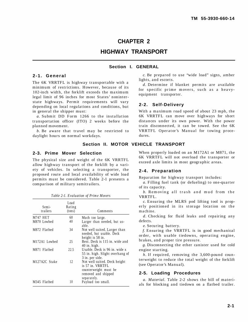
a. Material. When chain-tiedown cars are un-available, the shipper must supply materials forblocking and tiedown on the railcar. Table 3–2 is alisting of such materials. Note that either fourloops of 5/8-inch wire rope or eight loops of1/2-inch wire rope can be used.
b. Loading. To place the VRRTFL in the tie-down position on the railcar, use a crane ofadequate capacity (see para 4-4 for lifting guid-ance), or drive the forklift onto the railcar if asuitable ramp is available. Position the forklift sothat sufficient railcar tiedown points are available.Set the parking brake. Place the transmission inneutral. Rest the forks on shoring, or leave themin a raised position. Generally, on wood-deck rail-cars, rest the forks on the deck (or shoring), and onsteel-deck railcars, simply leave the forks raised18 to 24 inches above the deck.
c. Tiedowns and Blocking. Figure 3-1 and table3-3 provide instructions for restraining the forkliftagainst forces encountered in normal rail opera-tions. The rail loading restraint factors (LRF) usedin figure 3–1 are listed in appendix B.
3-1
TM 55-3930-660-14
Table 3-2. Bill of Materials for Transport by Railcar (Fig 3-1)
Item Quantity Description
Wire rope(8 loopsrequired)
Cable clamps(clips)
Thimbles
Lumber(nominal sizes)2 x 4 in.2 x 6 in.2 x 8 in.2 x 10 in.Nails16d
ProtectiveMaterialStrapping
About 160ft
16
32
16
36 ft*
12 ft*96 ft*32 ft*
4 pounds2 poundsAbout12 ft2
25 ft
1/2-in., improved plow steel,6X19 class, IWRC (indepen-dent wire rope core) or wire-strand core, nominal break-ing strength 23,00 pounds;Fed Spec RR-W-410 NSN4010-00-272-88485/8-in., Type I, single-saddle,wire-rope clamp, Fed SpecFF-C-4501/2-in., Crosby heavy-duty orone that exceeds Fed SpecFF-C-450 strength require-ments.1/2-in., Type III (heavy) splitoval construction (open pat-tern); Fed Spec FF-T-276Douglas-fir, or comparable;Fed Spec MM-L-751
Common, steel, flathead;bright or cement-coated; FedSpec FF-N-105Waterproof paper (tar paper)
20d
About Nonmetallic banding
required)
When 5/8-in. cable is used, the following quantitites apply:
Wire rope About ‘5/8-in., improved plow steel,(4 loops 70 ft 6x19 class, IWRC (indepen-
dent wire rope core) or wire-strand core, nominal break-ing strength 35,800 pounds;Fed Spec RR-W-410 NSN4 0 1 0 - 7 6 3 - 5 6 0 2
Cable clamps 8 3/4-in., Type I, single-saddle,(clips) wire-rope clamp, Fed Spec
FF-C-45016 5/8-in., Crosby heavy duty or
one that exceeds Fed SpecFF-C-450 strength require-ments.
Thimbles 8 5/8-in., Type III (heavy) splitoval construction (open pat-tern); Fed Spec FF-T-276.Use of thimbles is optionalon the VRRTFL fittings.
Table 3-3. Tiedown Procedures for Securing 6K VRRTFL onFlatcar (Fig 3-1)
Item Procedure
Chain Install at indicated locations. The number oftiedowns chains used will depend on chain
size/strength. Use eight 1/2-in. chains (4 ineach direction), or twelve 3/8-in. chains (6 ineach direction).
*NOTE*When chain-tiedown-equipped railcars arenot available, wire rope and wooden block-ing must be used.
Wire ropeloops
Cable clamps
Thimbles
BlockingStrapping
Each tiedown is made from one piece of 1/2-in.wire rope (8 required), or 5/8-in. wire rope (4required). Length as required (12 to 16 feet).Form a complete loop between forklift-trucktiedown provision and railcar stake pocket.The angle between the cables and railcar deck(as viewed from the side) should be as close to45° as possible. The wire rope ends must over-lap at least 24 inches. Tension the wire ropeby using two cable grippers and a chain-hoist(3-ton) or “come-along.”
Space clamps 3-3/4-in. apart as shown. With1/2-in. wire rope, use 1/2-in. cable clamps andalternately torque nuts to 65 ft-lb. (With 5/8-in. wire rope, use 5/8-in. cable clamps torquedto 95 ft-lb.)Use thimbles to protect cable at sharp bends.Attach to cable with cable clamps (5/8-in.clamps on 1/2-in. thimbles and 3/4-in. clampson 5/8-in. thimbles). Thimbles are optional forthe VRRTFL fittings.Position and nail blocking to railcar. Bandoperators’ cab to keep door closed in-transit.
*NOTE*To develop full cable loop workingstrength, cable clamp nuts must betorqued to:
65 ft-lb on 1/2-in. clamp nuts.95 ft-lb on 5/8-in. clamp nuts.
To ensure proper torque, alternatelytorque both nuts.
*Linear
3-2

TABLE 3-3.
para 3-4bpara 3-4a
TM 55-3930-660-14
Figure 3-1. Blocking and tiedown of 6K VRRTFL on rail flatcar.
3-3


TM 55-3930-660-14
CHAPTER 4
MARINE TRANSPORT
Section I. GENERAL
4-1 . Genera lThe 6K VRRTFL is marine transportable aboardmost general-purpose or roll-on/roll-off (RORO)ships. Most ships under the Military Sealift Com-mand charter have tiedown points such as D-ringsor other lashing anchors. When suitable lashingpoints are unavailable, wood blocking becomesnecessary. Marine loading restraint depends onthe expected sea state, ship size, and stow locationon the ship. Generally, the amount of restraintincreases for locations high and forward (or aft) inthe ship. The most severe conditions occur onexposed “weather-decks” (a ship’s crew may re-quire additional lashing). Below-deck locationsthat are closer to the vessel’s centers of gravityand rotation, will experience less severe loading.The blocking and tiedown procedures presented
(fig 4-1) allow for severe, below-deck conditions.(Contact MTMCTEA (see address in para 1-3) fora pamphlet on marine loading: MTMCTEA Pam-phlet 56-1, Marine Terminal Lifting Guidance.)
**CAUTION**
Ear protection (plugs) is needed whenworking on RORO ships with loud ventila-tor systems.
*NOTE*The entire vehicle must be checked to besure that loose items are properly secured.Maximum VRRTFL speed on ship loadingramps or decks is 3 mph or less.Fire extinguishers must be readily avail-able during ship loading and unloadingoperations.
Section II. SHIP LOADING
4-2. Preparat ionPreparation for sealift includes:
a. Preservation as required by TB 9-2320-281-35 for expected stowage (above or below deck).
b. Filling fuel tank between one-quarter andthree-quarters full for RORO operations
*NOTE*Because of limited cargo-hold ventilation,most general cargo ships will require thatthe fuel tank be drained and batterydisconnected.
c. Ensuring MLRS pod lifting tool is properlypositioned in its storage location on the machine.
d. Checking for fluid leaks and repairing anydefects.
e. Ensuring the VRRTFL is in good mechanicalorder, with usable tiedowns, operating engine,brakes, and proper tire pressure.
f. Disconnecting the ether canister used for coldengine starting.
4-3. Loading Proceduresa. Material. When ship’s lashing gear is un-
available, the shipper must supply tiedown materi-als. The VRRTFL is shown in figure 4-1 alignedfore and aft with the ship. The loading restraintfactors (LRF) used in figure 4-1 are listed in
appendix B. Table 4-1 is a listing of such materi-als.
Table 4-1. Bill of Materials for Transport by Ship
Item Quantity Description
Wire rope
Cableclamps(clips)
Thimbles
About 80-ft 1/2-in., improved plow steel, 6x19class, IWRC (independent wire ropecore) or wire-strand core, nominalbreaking strength 23,000 pounds;Fed Spec RR-W-410 NSN4010-00-272-8848
8 5/8-in., Type I, single-saddle, wire-rope clamp, Fed Spec FF-C-450
16 1/2-in., Crosby heavy-duty or onethat exceeds Fed Spec FF-C-450strength requirements.
8 1/2-in., Type III (Heavy) split ovalconstruction (open pattern); Fed SpecFF-T-276
When suitable ship’s lashing points are unavailable, blockingbecomes required.
Lumber Douglas-fir, or comparable;(nominal Fed Spec MM-L-751sizes)2 x 6 in. 20 ft*4 x 6 in. 140 ft*Nails Common, steel, flathead; bright or16d 1 pound cement-coated; Fed Spec FF-N-10540d 2 pounds
*Linear4-1

TM 55-3930-660-14
b. Loading. Position the VRRTFL as indicated inthe stow plan, so sufficient tiedown points areavailable. Set the parking brake. Place the trans-mission in neutral. Rest the forks on shoring, orleave them raised about 10 inches off the deck.Disconnect the battery (if required by the ship’smaster) once the VRRTFL is positioned aboard ship.
c. Tiedoum and Blocking. Figure 4-1 and table4-2 provide instructions for restraining the forkliftagainst forces encountered in severe marine condi-tions (para 4-1).
Table 4-2. Tiedown Procedures for Securing 6K VRRTFL in aCargo Ship Hold (Fig 4-1)
Item Procedure
Wire rope Each tiedown is made from one piece of 1/2-in.loops (4 wire rope. Length as required. Form a com-required) plete loop between forklift-truck and ship tie-
down provisions. The angle between the cablesand deck (as viewed from the side) should beas close to 45° as possible. The wire rope endsmust overlap at least 24 inches. Tension thewire rope by using two cable grippers and achain hoist (3-ton) or “come-along.”
Cable clamps Space clamps 3-3/4 inches apart as shown.Use 1/2-in. cable clamps and alternatelytorque nuts to 65 ft.-lb.
Thimbles Use thimbles to protect cable at sharp bends.Attach to cable with 5/8-in. cable clamp.Thimbles are optional for the VRRTFLfittings.
Blocking Position and nail blocking.
*NOTE*The methods described in this chapter forlifting and securing vehicles are recom-mended procedures. Other methods ofhandling and stowage may be used pro-vided they ensure safe delivery without
damage.To develop full cable-loop workingstrength, torque 1/2-in. cable clamp nutsto 65 ft-lb. To ensure proper torque, alter-nately torque both nuts.Cable-loop working strength (two loadedcables) is 80 percent of the cable breakingstrength. Example: 23,000 x 2 x 0.8 =36,800 lb for 1/2-in. cable.
4-4. Lifting Operations
Shiploading will often require lifting of theVRRTFL into position aboard ship. Shipside andshoreside cranes are usually rated in long tons(LTON), 2,240 pounds, and/or metric tons, 1000kilograms. To lift the VRRTFL, a crane andsling-set capacity of at least 12 LTON or 13 metrictons is needed. See figure 4–2.
**WARNING**Crane lifting operations are inherentlydangerous. Avoid being under overheadloads.
4 -2

Figure 4-1.
TA
BLE
4-2
TM
5
5-3
93
0-6
60
-14
4-3

TM 55-3930-660-14
Figure 4-2. Crane lifting of the 6K VRRTFL.
4 -4

TM 55-3930-660-14
CHAPTER 5
AIR TRANSPORT
Section I.
5-1. GeneralThe 6K VRRTFL is air transportable. The ship-ping unit must ensure that the VRRTFL is prop-erly prepared for air transport before reaching themarshaling area. The shipping unit will assist theaircraft loadmaster/crew in loading and tyingdown the VRRTFL. The loadmaster-prepared loadplan for the actual aircraft mission will determinespecific loading limitations, tiedown patterns, andtroop seating availability. The loading restraintfactors (LRF) used in aircraft tiedown are listed inappendix B.
5 -2 . Sa fe tySafety considerations and precautions for the 6KVRRTFL air transport are:
**CAUTION**Personnel must wear ear protection(plugs) at all times while working on theflightline.
GENERAL
Members of loading teams should notwear rings.
*NOTE*Fire extinguishers must be readily avail-able during aircraft loading and unload-ing operations.The vehicle maximum speed within 25feet of any aircraft is 5 mph. On loadingramps or inside the aircraft, the vehicleshould not exceed 3 mph.Personnel must not refuel or otherwiseservice the VRRTFL within 50 feet of anaircraft.
5-3. Hazardous Material
Shippers must provide written notification beforeshipping dangerous or hazardous materials aboardmilitary or DOD contract aircraft. Details arecovered in TM 38-250/AFR 71-4, Preparation ofHazardous Materials for Military Air Shipment.
Section II. TRANSPORT by CARGO AIRCRAFT
5-4. USAF Cargo AircraftThe 6K VRRTFL is certified for airlift aboard allMilitary Airlift Command (MAC) prime missioncargo aircraft. Airlift on the C-130 will requireremoval of the 3,600-pound counterweight to re-duce axle load.
5-5. Civil Reserve Air Fleet (CRAF)The 6K VRRTFL exceeds the capability of allaircraft in the CRAF.
5-6. Preparat ion
The deploying unit must prepare the VRRTFL forairlift. Preparation will include:
a. Cleaning dirt, mud, snow, ice, and trash fromthe VRRTFL.
b. Ensuring the VRRTFL has no fluid leaks (oil,fuel, hydraulic, and coolant).
c. Ensuring the VRRTFL is in good mechanicalorder, with usable tiedowns; operating engine,brakes, and hydraulic system; and proper tirepressure.
d. Marking the shipping weight and center ofbalance location on both sides of VRRTFL.
e. Securing battery, and tightening battery caps.f. Filling the VRRTFL fuel tank between one-
quarter and one-half full, and securely closing fueltank to prevent spillage.
*NOTE*Fuel tank can be no more than one-halffull on other than contingency flights.
g. When required, remove and palletize thecounterweight. The VRRTFL Unit, Direct Support,and General Support Maintenance Manual, TM10-3930-660-24, provides details on counter-weight removal and installation.
*NOTE*A second forklift truck is needed to re-move the VRRTFL counterweight. Re-moval requires lifting the 3,600-poundcounterweight on the fork ends. A forklifttruck with a minimum capacity of 5,000pounds (using standard forks) will beneeded to handle the counterweight.
5-1


TM 55-3930-660-14
APPENDIX A
REFERENCES
A-1. Army Regulations (AR)
55-29 Military Convoy Operations in CONUS55-80 Highways for National Defense55-162 Permits for Oversize, Overweight, or other Special Military Movements on Public
Highways in the United States55-355 Defense Traffic Management Regulation70-44 DOD Engineering for Transportability70-47 Engineering for Transportability746-1 Packaging of Army Material for Shipment and Storage
A-2. Field Manuals (FM)
5-345-3655-1555-17
A-3 . Supply
700-20
Engineer Field DataRoute Reconnaissance and ClassificationTransportation Reference DataTerminal Operations Coordinator’s Handbook
Bulletins (SB)
Army Adopted/Other Items Selected for Authorization/List of Reportable Items
A-4. Technical Bulletins (TB)
55-46-1 Standard Characteristics (Dimensions, Weight, and Cube) for Transportability of Mili-tary Vehicles and Other Outside/Overweight Equipment
A-5. Technical Manuals (TM)
38-236 Preparation of Freight for Air Shipment(AFP 71-8)
38-250 Packaging and Materials Handling Preparation of Hazardous Materials for Military Air(AFR 71-4) Shipment
55-500 Marine Equipment Characteristics and Data55-2200- Transportability Guidance: Application of Blocking, Bracing, and Tiedown Materials for
001-12 Rail Transport
A-6. Air Force Manuals .
TO IC-5A-9 Loading Instructions, USAF Series C-5 AircraftTO IC-130E-9 Loading Instructions, USAF Series C-130 AircraftTO IC-141B-9 Loading Instructions, USAF Series C-141 Aircraft
A-7. Other publicationsa. Code of Federal Regulation, Title 49—Transportation Parts, 107-179 and Title 46-Shipping, Part 146
Available from: Superintendent of DocumentsUS Government Printing OfficesWashington, DC 20402
b. Association of American Railroads, Rules of Governing the Loading of Commodities on Open-Top Carsand Trailers
Section No. 1–General RulesSection No. 6–Rules Governing the Loading of Department of Defense Materiel on Open-Top CarsAvailable from: Association of American Railroads
A-1

TM 55-3930-660-14
50 F Street, NWWashington, DC 20001-1564
c. 4th Transportation Command Pamphlet 55-2, Tiedown Guide of Rail MovementAvailable from: Commander
1st Transportation Movement Control AgencyATTN: AEUTR-MCA-TAAPO New York 09451-4000
A-2

TM 55-3930-660-14
APPENDIX B
LOADING RESTRAINT FACTORS
The loading restraint factors (LRFs) used for surface and air modes are the "G" (acceleration of gravity)loading factors that can be expected in military transport. The tiedown arrangements shown in the 6KVRRTFL TGTM are based on the following:
—restraint factors are applied independently in each direction.—restraint load (GVW times the LRF) was resolved into resultant lashing loads, allowing for tiedown
angle.–lashing loads are less than safe working load (SWL) of the restraint (that is, wire rope).
Highway:
The Transportation Engineering Agency highway LRFs are:0.7 in the forward direction (relative to the transporter).0.3 in the aft and vertical directions.0.1 in the lateral direction.
Rail:
The Association of American Railroads recommended rail LRFs are:3.0 in the longitudinal direction (relative to the railcar).2.0 in the lateral and vertical directions.
Marine:
The Military Sealift Command (MSC) design LRFs are:1.2 in the lateral direction (relative to the ship).0.7 in the longitudinal direction.0.2 in the vertical direction.
MSC LRFs are for severe conditions.
Actual marine LRFs vary. Marine tiedown restraint depends on the size of ship (decreasing on largervessels), the expected sea state to be encountered, and the stow location on a given ship. Generally, therestraint required will increase for locations high and forward (or aft) in the ship. The most severeconditions occur on exposed “weather decks,” where strong wind and wet conditions add to the problem. Aship’s crew may require additional lashing on exposed decks. Below-deck locations that are closer to thevessel’s centers of gravity and rotation will experience less severe motion. The blocking and tiedownprocedures presented (fig 4–1) will allow for severe, below-deck conditions.
Air:The USAF aircraft LRFs are:
3.0 in the forward direction (relative to the aircraft).2.0 in the vertical direction.1.5 in the aft and lateral directions.
B-1


TM 55-3930-660-14
APPENDIX C
ESTIMATING TIEDOWNS
The number of lashings required to safely tie down the VRRTFL for highway transport on a typicaltruck/semitrailer can be estimated in the following manner:
STEP 1 – Determine the amount of longitudinal restraint needed. [With this method, the requiredvertical and lateral restraint is covered by the longitudinal factor or factors.]
–The highway loading restraint factor (LRF) is 0.7 (from app B) in the forward direction:27,100 (VRRTFL GVW) x 0.7 = 18,970 pounds
–The highway LRF is 0.3 in the aft direction:27,100 X 0.3 = 8,130 pounds
STEP 2 – Determine the number of chains needed.–The angle to semitrailer deck and the angle to the side are assumed to be 45°. [cos 45 x cos 45 = 0.5]–The SWL of 3/8-in. chain (from table 2-2) is 8,250 pounds:
No. of forward loading chains = 18,970 = 4.6 (rounded up to 5)8,250 X 0.5
While 5 chains satisfy the equation, 6 chains are needed for a symmetric (side-to-side) tiedownarrangement. Therefore, use 6 chains to prevent the VRRTFL from moving forward on the semitrailer.
No. of aft loading chains = 8,130 = 1.9 (rounded up to 2)8,250 X 0.5
Use 2 chains to prevent the VRRTFL from moving aft on the semitrailer.
NOTE:This method is more conservative than the “Highway Transport” chapter. Fewer chains are used in
Figure 2-1, “Tiedown of 6K VRRTFL on a flatbed semitrailer,” because the figure is based on the actualtiedown-lashing angles [angle to semitrailer deck (side view) and angle to the side (top view)].
C-1


TM 55-3930-660-14
By Order of the Secretary of the Army:
Official:
CARL E. VUONOGeneral, United States Army
Chief of Staff
PATRICIA P. HICKERSONBrigadier General, United States Army
The Adjutant General
Distribution:To be distributed in accordance with DA Form 12-34-E, block 4215, requirements for TM
55-3930-660-14.
* U.S. G.P.O.: 1991-281-483:40073


PIN: 068501-000

This fine document...
Was brought to you by me:
Liberated Manuals -- free army and government manuals
Why do I do it? I am tired of sleazy CD-ROM sellers, who take publicly available information, slap “watermarks” and other junk on it, and sell it. Those masters of search engine manipulation make sure that their sites that sell free information, come up first in search engines. They did not create it... They did not even scan it... Why should they get your money? Why are not letting you give those free manuals to your friends?
I am setting this document FREE. This document was made by the US Government and is NOT protected by Copyright. Feel free to share, republish, sell and so on.
I am not asking you for donations, fees or handouts. If you can, please provide a link to liberatedmanuals.com, so that free manuals come up first in search engines:
<A HREF=http://www.liberatedmanuals.com/>Free Military and Government Manuals</A>
– SincerelyIgor Chudovhttp://igor.chudov.com/
– Chicago Machinery Movers