transposal ultra evacuation unit technical...
TRANSCRIPT

Ultra Evac Technical Manual 2/8/2013 GD-99013 Rev. D
Transposal Ultra Evacuation Unit
Technical Manual
Model No.: UL-EV100

Ultra Evac Technical Manual 2/8/2013 GD-99013 Rev. D

Ultra Evac Technical Manual 2/8/2013 GD-99013 Rev. D

Ultra Evac Technical Manual 2/8/2013 GD-99013 Rev. D
Contents
Introduction ------------------------------------------------------------------------------------------- 1
Important Information ----------------------------------------------------------------------------------------------- 2
Intended Use ---------------------------------------------------------------------------------------------------------- 2
Equipment Description ----------------------------------------------------------------------------------------------- 2 User/Patient Safety --------------------------------------------------------------------------------------------------- 3
Technical Description -------------------------------------------------------------------------------- 4
Specifications ---------------------------------------------------------------------------------------------------------- 4
Operation ---------------------------------------------------------------------------------------------- 6
Safety Features ------------------------------------------------------------------------------------------------------- 7
Environmental Protection -------------------------------------------------------------------------------------------- 7
Waste Disposal Accessories ----------------------------------------------------------------------------------------- 7 MSDS Sheet for Bleach and Enzyme ------------------------------------------------------------------------------- 7
Reusable Suction Reservoir Use and Processing ----------------------------------------------------------------- 8
Instructions for Use -------------------------------------------------------------------------------------------------- 9 Processing Reservoirs --------------------------------------------------------------------------------------------------------------------------- 9 Reprocessing Reservoirs (Optional) ---------------------------------------------------------------------------------------------------------- 9 Prepare Cart for Next Case -------------------------------------------------------------------------------------------------------------------- 9 Replacing Bleach & Enzyme Bottles --------------------------------------------------------------------------------------------------------- 10 Reprocessing Cycle Descriptions: ------------------------------------------------------------------------------------------------------------ 10 Performing Verify Bleach Cycle: -------------------------------------------------------------------------------------------------------------- 10 Unit Information and Error Messages ------------------------------------------------------------------------------------------------------- 11 Periodic Maintenance -------------------------------------------------------------------------------------------------------------------------- 11 Troubleshooting Guide ------------------------------------------------------------------------------------------------------------------------- 12 DMS Technical Service - Information -------------------------------------------------------------------------------------------------------- 12 Symbols & Labels ------------------------------------------------------------------------------------------------------------------------------- 13 Consumables and Accessories ---------------------------------------------------------------------------------------------------------------- 14 Use of Single Use Lids and Manifolds ------------------------------------------------------------------------------------------------------- 14
Installation ------------------------------------------------------------------------------------------- 15
Protective Packaging & Unpacking ------------------------------------------------------------------------------- 15
Site Preparation ----------------------------------------------------------------------------------------------------- 15 Utilities Needed for Installation -------------------------------------------------------------------------------------------------------------- 16 Space --------------------------------------------------------------------------------------------------------------------------------------------- 16 Water Supply ------------------------------------------------------------------------------------------------------------------------------------ 16 Electrical ----------------------------------------------------------------------------------------------------------------------------------------- 16 Sanitary Sewer (Drain) ------------------------------------------------------------------------------------------------------------------------ 16 Backflow Preventers---------------------------------------------------------------------------------------------------------------------------- 16
De-install/Disconnect Instructions ------------------------------------------------------------------------------- 18
Equipment Storage ------------------------------------------------------------------------------------------------- 18
Maintenance ----------------------------------------------------------------------------------------- 19
Qualifications for Service Personnel ----------------------------------------------------------------------------- 19
Service Warnings --------------------------------------------------------------------------------------------------- 19 Additional Information --------------------------------------------------------------------------------------------- 19
Routine Maintenance ----------------------------------------------------------------------------------------------- 20
Replacement Items ------------------------------------------------------------------------------------------------- 20

Ultra Evac Technical Manual 2/8/2013 GD-99013 Rev. D
Fluid Paths and Wiring Diagrams --------------------------------------------------------------------------------- 21
Preventative Maintenance ----------------------------------------------------------------------------------------- 25
Company Information ----------------------------------------------------------------------------- 26
Contact Information ------------------------------------------------------------------------------------------------ 26
Limited Warranty ----------------------------------------------------------------------------------- 27
List of Tables
Table 1 – Equipment Specifications .................................................................................................... 4
Table 2 – Site Utilities for Installation ............................................................................................... 16 Table 3 – Preventative Maintenance Schedule .................................................................................. 25
List of Figures
Figure 1 – Ultra Evac Unit Dimensions and Features (Dim.=inch(cm)) ----------------------------------------- 5
Figure 2 – TP-DL2800 Single Use Lid --------------------------------------------------------------------------------- 6
Figure 3 – UL-CL500 Single Use Manifold ---------------------------------------------------------------------------- 6
Figure 4 – Ultra Fluid Cart Connected to the Ultra Evac Unit ----------------------------------------------------- 6
Figure 5 – Coupler Insertion ------------------------------------------------------------------------------------------- 9
Figure 6 – Cycle Complete Screen ------------------------------------------------------------------------------------ 9
Figure 7 – Cleaning Cycles Screen ------------------------------------------------------------------------------------ 9 Figure 8 – Bleach and Enzyme Bottles ----------------------------------------------------------------------------- 10
Figure 9 – Ultra Evac Unit Architectural Drawing ----------------------------------------------------------------- 17
Figure 10 – Environmental Conditions ------------------------------------------------------------------------------ 18
Figure 11 – Ultra Evac Unit Fluid Flow Diagram ------------------------------------------------------------------ 21
Figure 12 – Ultra Evac Unit Wiring Diagram ----------------------------------------------------------------------- 22
Figure 13 – Ultra Evac Unit Board Schematic --------------------------------------------------------------------- 24

Ultra Evac Technical Manual 1 2/8/2013
GD-99013 Rev. D
Introduction
The Transposal Ultra Evacuation Unit (evac) is designed to empty, clean, and rinse the Ultra Fluid
Carts (carts). The evac is used to process the Ultra Quad Cart (4 reservoirs) and the Ultra Duo Cart
(2 reservoirs) after they have been used to collect fluids in the surgical procedure.
Two manuals are provided with this equipment and are shipped with the equipment during the initial
installation. Copies of these manuals are available to any Dornoch Medical Systems, Inc. (DMS)
customer upon request.
The two different manuals are as follows:
Instructions for Use Manual – This manual is designed to instruct users in the correct
operation of the evac as well as safety considerations associated with the unit.
Technical Service Manual – This manual includes operation instructions, installation &
disconnection instructions, technical specifications, and preventative maintenance
procedures for the unit.
This is the Technical Service Manual, and it is broken into seven sections including:
Introduction
Technical Description
Operation
Installation
Maintenance
Company Information
Limited Warranty
As a supplement to these two manuals, instructional video(s) are available to assist maintenance
personnel in their understanding of the equipment‟s operation and the maintenance procedures
needed. If required, DMS service personnel can be contacted 24-hours a day at 1-888-466-6633.

Ultra Evac Technical Manual 2 2/8/2013
GD-99013 Rev. D
Important Information
Please read this manual and follow all instructions. The words WARNING, CAUTION and NOTE have
special meanings and should be reviewed.
WARNING: Disregarding WARNING information may compromise the safety of the patient and/or health care staff and may result in injury.
CAUTION: Disregarding CAUTION instructions may compromise product reliability and may result in damage.
NOTE: NOTE information supplements and/or clarifies procedural information.
A triangle with an exclamation point alerts the health care professional to read and understand the
accompanying instructions, especially the operating, maintenance and safety information.
Intended Use The intended use of the evac is to process the carts after they have collected surgical fluids. The
evac will empty, clean, and rinse the reusable suction reservoirs on the carts.
Equipment Description The evac is a standalone unit that can automatically process a cart. The evac empties, cleans, and
rinses the carts during the process. The Ultra System significantly reduces employee exposure to
potentially infectious body fluids, while eliminating up to 70% of Operating Room red bag waste.
The evac processes Ultra Duo and Ultra Quad carts for reuse. Once installed, operators simply
connect the evac to a dirty cart with the evac‟s coupler. With a touch of a button the cart is
automatically emptied, cleaned, and rinsed. With the addition of a new single use lid, they are ready
for reuse within the facility.

Ultra Evac Technical Manual 3 2/8/2013
GD-99013 Rev. D
User/Patient Safety
WARNINGS:
Before using this system, read and understand the
information in this manual.
DO NOT use this system outside the scope of the
defined indications for use.
Upon initial receipt and before each use, operate
the equipment and inspect each component for
damage. DO NOT use any component if damage is
apparent.
Handling biohazard waste is potentially dangerous.
ALWAYS follow current local regulations
governing biohazard waste to safely handle and
dispose of surgical fluid waste.
The Blood-borne Pathogens Standards, provided
by the Occupational Safety and Health Association
(OSHA), requires that all workers, having exposure
to “potentially infectious materials”, should wear
the correct personal protection equipment.
To avoid the risk of electrical shock, this equipment
must be connected to electrical outlet with a
protective earth ground.
Verify all access doors are securely in place before
operating this unit.
Use only Dornoch Medical Systems, Inc. approved
accessories. Do not connect items to this system
that are not designed for or specified for use with
this system.
Perform recommended maintenance as indicated in
these instructions. Only trained and experienced
health care professionals should maintain this
equipment.
No user serviceable parts inside the unit. Contact
Dornoch Medical Systems, Inc. customer service if
an issue arises. Only authorized service personnel
should open any of the access covers on this
equipment. User operation does not require access
to these areas.
ALWAYS use the handle to move the cart. DO
NOT push or pull the cart by grasping any
receptacle or the outer surface. NEVER hang any
heavy object from the cart handles.
ALWAYS have more than one person unpack and lift the equipment off the shipping pallet.
No incline planes of operation.
DO NOT use the system if leakage of surgical fluid
waste occurs. Disconnect power immediately and
call Dornoch Medical Systems, Inc. customer
service.
DO NOT allow fluid of any kind to spill directly
onto the exterior surface of the electrically-powered
evac.
DO NOT use the evac until it has been installed
and tested for proper operation.
This unit uses both bleach and enzyme in its
operation. When replacing bottles, always wear the
appropriate Personal Protective Equipment. Use
only Dornoch Medical Systems, Inc. approved
Bleach and Enzyme to avoid damage to the system
components.
This equipment is not suitable for use in the
presence of flammable anesthetic mixtures with air,
oxygen or nitrous oxide. Is not intended for use
with AP or APG equipment.
Hot Water Temperatures higher than 118 0F can
cause damage to the unit.
There are no known significant risks of reciprocal
interference posed by the presence of this
equipment or its operation in either the operating
room suites or other areas when used during
specific investigations and/or treatments.
There are no known potential electromagnetic or
other interferences between this unit and other
devices located and/or operated within the area of
the operating room suites.
Ultra Evac Technical Manual 4 2/8/2013 GD-99013 Rev. D
Technical Description
Specifications
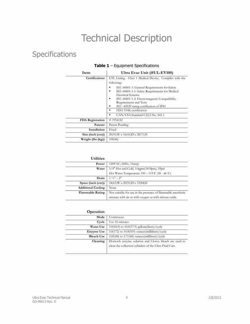
Table 1 – Equipment Specifications
Item Ultra Evac Unit (#UL-EV100)
Certifications ETL Listing - Class 1 Medical Device. Complies with the
following:
IEC-60601-1: General Requirements for Safety
IEC-60601-1-1: Safety Requirements for Medical Electrical Systems
IEC-60601-1-2: Electromagnetic Compatibility - Requirements and Tests
IEC- 60529 rating certification of IP41
FDA 510K certification
CAN/CSA Standard C22.2 No. 601.1
FDA Registration # 1954182
Patents Patent Pending
Installation Fixed
Size (inch (cm)) 20(51)W x 16(41)D x 28(71)H
Weight (lbs (kg)) 100(46)
Utilities
Power 120VAC, 60Hz, 15amp
Water 3/4" Hot and Cold, 5.0gpm(18.9lpm), 55psi
Hot Water Temperature 100 – 115oF (38 - 46 oC)
Drain 1 ½” – 2”
Space (inch (cm)) 24(61)W x 20(51)D x 33(84)H
Additional Cooling None
Flammable Rating Not suitable for use in the presence of flammable anesthetic
mixture with air or with oxygen or with nitrous oxide.
Operation
Mode Continuous
Cycle 5 to 16 minutes
Water Use 5.0(18.9) to 10.0(37.9) gallons(liters)/cycle
Enzyme Use 5.8(172) to 10.8(319) ounces(milliliters)/cycle
Bleach Use 2.85(84) to 5.7(168) ounces(milliliters)/cycle
Cleaning Dornoch enzyme solution and Clorox bleach are used to
clean the collection cylinders of the Ultra Fluid Cart.

Ultra Evac Technical Manual 5 2/8/2013 GD-99013 Rev. D
Figure 1 – Ultra Evac Unit Dimensions and Features (Dim.=inch(cm))
Power
Indicator
Evac
Coupler
Waste
Hose
Power Inlet
Coupler
Hoses
Hot
Water
Inlet
Leveling
Legs
33
(84)
20(51)
16(41)

Ultra Evac Technical Manual 6 2/8/2013 GD-99013 Rev. D
Operation The Transposal Ultra Infectious Fluid Management System consists of carts for fluid collection and the
evac for fluid disposal. Carts collect up to 52 liters of surgical fluids without the need to tandem multiple
suction canisters. In addition, each Ultra unit‟s on-board vacuum pump replaces or improves facility wall
vacuum performance when inadequate suction is otherwise present.
Once connected to a 120 VAC electrical outlet, cart reservoirs collect fluids from one to three separate sites.
Ultra Duo Fluid Carts have two 16.5 liter reservoirs and Ultra Quad Fluid Carts have four 13.0 liter
reservoirs. Reservoirs can be used with wall vacuum and/or the on-
board vacuum pump.
A single use lid (Figure 2) or manifold (Figure 3) is used to make
suction tube connections from the field to the cart. The Ultra Duo
uses two single use lids or manifolds and the Ultra Quad uses four lids
or manifolds. New lids are pressed on to the top of cart reservoirs or
new manifolds are inserted into the housings. On carts with the single
use lid, only one sealed, cleaned reservoir is used per patient. Carts are
removed from the OR suite for processing after all reservoirs have
been used, or at the end of the day. On carts with the single use cart
manifold, the manifold is changed between patients to allow for multi-
patient fluid collection. The carts are removed for processing at the
end of every day.
Cart processing is accomplished with
an evac (Figure 4) located in an OR
utility closet or decontamination
room. Evacs empty, clean, and rinse
reservoirs for reuse. The evac‟s water,
drain, and sensor lines are easily
connected to the cart using a drip-less
all-in-one coupler connection. Carts
are powered by the evac coupler
connection during reservoir
processing.
Figure 2 – TP-DL2800 Single Use Lid
Figure 3 – UL-CL500 Single Use Manifold
Figure 4 – Ultra Fluid Cart Connected to the Ultra Evac Unit

Ultra Evac Technical Manual 7 2/8/2013 GD-99013 Rev. D
Safety Features The Ultra Fluid Carts have numerous built in safety features including:
Closed System Design. The Ultra Fluid Carts are designed to confine and contain fluids
during disposal. Personnel never open cylinders that contain collected fluids.
Interactive Controls. The Ultra Fluid Carts‟ high-tech control system guides users through unit operation while monitoring key functions.
Bleach Cycle Monitoring. Continuous automatic monitoring of the bleach cycle is accomplished with electronic sensors within the Ultra Evac Unit.
Environmental Protection Infectious Waste: None
Waste Disposal Accessories There are no current accessories required for disposal from this unit.
MSDS Sheet for Bleach and Enzyme MSDS sheets are available upon request by calling DMS at 1-888-466-6633.

Ultra Evac Technical Manual 8 2/8/2013 GD-99013 Rev. D
Reusable Suction Reservoir Use and Processing Reservoir Processing.
WARNING: Follow the current local regulations governing biohazard waste to safely handle and
dispose of surgical fluid waste.
Carts should be processed when all of the collection reservoirs have been used or at the end of the day.
Designated OR, SPD, or housekeeping personnel shall empty and clean used carts with the evac.
Processing shall be accomplished in accordance with manufacturer‟s directions. After processing, wipe
down the cart with a hospital approved bleach wipe (Sani-Cloth Bleach Germicidal Wipe (DMS# UL-
BW100), Clorox: Germicidal Wipes or equivalent) and place clean lids onto the cart. Non-approved wipes
may cause surface damage to the equipment.
Bleach Verification. Daily visual verification of the cart/evac systems bleach cycle shall be completed
using a Verification Log Kit (#TP-VL100). Continuous automatic monitoring of the bleach cycle is
accomplished with electronic sensors within the evac. If an error is detected, the message shall be reported
to an immediate supervisor.
Single Use Items Storage. A supply of new single use reservoir lids or manifolds shall be kept in a
designated clean storage area, and near any point of use.
Preparing Reservoirs for Use. A new single use lid (TP-DL2800) or manifold (UL-CL500) shall be
placed onto the reservoir in a designated clean area. The user must verify the white hydrophobic filter is in
place on the lid or manifold. If it is the first case of the day or the cart has just been processed, verify the
reservoirs are clean prior to installing a new single use lid.
Cart Cleaning. Ultra Fluid Carts should be processed when all of the collection reservoirs have been
used or at the end of the day.
Cart Transportation. Used carts shall be sealed and transported to the evac for processing. Before
processing the cart, verify all of the ports on the single use lids or manifolds are capped.

Ultra Evac Technical Manual 9 2/8/2013 GD-99013 Rev. D
Instructions for Use
Processing Reservoirs
Step 1 – Insert the coupler into the receiver and gently press the handle down. (Figure 5)
Step 2 – Verify that all reservoirs have green lids/manifolds and that all of the ports are capped.
CAUTION: Caps must be on all ports prior to washing to prevent
wash fluid from leaking out onto the top of the cart during processing.
Step 3 – Follow the on-screen instructions to start the processing cycle.
Step 4 – When processing is complete (Figure 6), verify the reservoirs are clean. If reservoirs are not clean, proceed to the Reprocessing Reservoirs instructions below.
Step 5 – Press the “REMOVE COUPLER” button and remove the coupler by first pressing down gently on the handle and then lifting up while pulling the coupler out of the receiver. Place the receiver in the storage unit.
CAUTION: ALWAYS press down gently on the handle prior to
removing the coupler. Failure to do so could cause damage to the
equipment.
Reprocessing Reservoirs (Optional)
Step 1 - Access the reprocessing options by pressing the “OPTIONS” button in the upper right corner. (Figure 6)
Step 2 - Select the desired reservoir(s) and the cleaning cycle and then press the “START PROCESS” button to perform the selected cycle. (Figure 7) See “Reprocessing Cycle Descriptions”.
Prepare Cart for Next Case
Step 1 – Remove the used lids/manifolds from each reservoir and discard according to hospital policy. Processed lids/manifolds can be identified with a blue filter.
Step 2 – Wipe down the cart with a hospital approved bleach wipe. (Sani-Cloth Bleach Germicidal Wipe (DMS# UL-BW100), Clorox: Germicidal Wipes or equivalent)
Step 3 – Move the cart to a clean area and replace the lids/manifolds.
Figure 5 – Coupler Insertion
Figure 6 – Cycle Complete Screen
Figure 7 – Cleaning Cycles Screen

Ultra Evac Technical Manual 10 2/8/2013 GD-99013 Rev. D
Replacing Bleach & Enzyme Bottles
Evac Station bleach and enzyme bottles must be replaced when indicated on the cart‟s display during processing. Bottle replacement is completed as follows:
CAUTION: ALWAYS use approved enzymatic cleaner and fresh Clorox bleach when replacing chemicals (Clorox bleach slowly looses strength over time). Other chemicals may damage the evac and cart.
Step 1 – Remove lid and pickup tube from empty container. (Figure 8)
Step 2 – Open a new bottle, place the bottle into the top of the unit, insert the pickup tube into the bottle, and secure the lid.
Step 3 – Dispose of the empty bottle per hospital policy.
Figure 8 – Bleach and Enzyme Bottles
Reprocessing Cycle Descriptions:
3L Soak – Cycle applies 10 ounces of enzyme with 3 liters of water to help break up any clots that may be
remaining in the bottom of the reservoir at the end of the cycle. Let the fluid soak for at least one hour for
best results.
Full Soak – Cycle fills reservoir to the 13L (Quad) or 16.5L (Duo) mark along with about 10 ounces
of enzyme. This cycle is used if there are spots on the reservoir that are not coming off during a
wash. Let the fluid soak for at least one hour for best results.
Rewash – Cycle will attempt to clean the selected reservoir(s) again using wash water and enzyme. The
cycle will apply the solution and pause several times during the rewash cycle.
Performing Verify Bleach Cycle:
To verify that the unit is applying bleach, place the unit into the check for bleach mode by using the
following steps:
1. Hook a cart to the evac.
2. Press the button to confirm the lids are on the reservoirs.
3. On the second screen press the options button in the upper right hand corner.
4. Select "Bleach Check" and press the "Start Process" button.
5. The cart will process through bleach application and will give instructions on the screen.
6. Remove a test strip from its container.
7. Remove the lids and touch one end of the test strip to a droplet on the bottom of the first lid and
use the other end of the test strip to touch a droplet on the bottom of the other lid.
8. A purple test strip indicates a pass. Any other color indicates a failed result.
9. Replace the lids onto the reservoirs and press the button on the screen to complete processing.
10. If the test strip turns purple the canisters are having bleach applied to them.
11. If the test strips do not turn purple, call DMS at 1-888-466-6633 and ask for service.

Ultra Evac Technical Manual 11 2/8/2013 GD-99013 Rev. D
Unit Information and Error Messages
The cart display provides the operator feedback for common operating errors encountered during the evac
processing cycle. The most common messages are described below. Please call DMS at 1-888-466-6633 for
assistance with any error message.
Warning or Error Action Required
Leak Detected: This message indicates that there
has been a leak detected within the evac. The unit
alarms at the end of the cycle when cart has
completed the cleaning process.
Check all supply lines for correct connection. Call
service if necessary.
Replace Bleach: This message indicates that the unit
has run out of bleach. The unit alarms at the end of
the cycle and when replaced will go back and apply
bleach to the reservoirs as necessary.
Replace the bleach with a new gallon.
Replace Enzyme: This message indicates that the
Enzyme solution has run out. The unit alarms at the
end of the cycle when the reservoirs have completed
the cleaning process.
Replace the enzyme with a new gallon.
Valve Error: This message indicates one of the evac
valves is not operating properly. The error displays
after the reservoirs have completed the cleaning
process.
Contact service with the specific valve error.
Communication Error: This error indicates that the
cart and the evac are hooked together but there is no
data transfer between the two.
Uncouple the evac from the cart. Wipe the
contacts on the coupler and in the receiver with
alcohol and try to hook them together again. Call
service if the problem continues.
Periodic Maintenance
Interval Activity
Prior to each use Inspect the coupler hose for twisting or any leaks in the hoses. Inspect the coupler
housing for any cracks or other defects that may affect function. DO NOT use if the
equipment if damage is present.
As required Check the level of the enzyme and bleach in the bottles. Replace the bottles as
required.

Ultra Evac Technical Manual 12 2/8/2013 GD-99013 Rev. D
Troubleshooting Guide
Problem: Unit Will Not Operate Possible Solutions: 1. Check that the machine is plugged into an operational outlet.
2. Call maintenance to replace the Unit‟s internal fuses.
Problem: Coupler Engages but Cart Will Not Power Up Possible Solutions: 1. Remove the coupler and try again.
2. Clean the electrical contacts with a cotton swab and alcohol. Try to activate the cart again.
3. Call DMS at 1-888-466-6633.
Problem: Chemical Flow Error Even With New Gallons Possible Solutions: 1. Tighten connections on the pickup tubes in the chemical bottles.
2. Clean chemical pickup tubes in warm water.
3. Call DMS at 1-888-466-6633.
Problem: Reservoirs are Not Washing
Possible Solution:
1. Verify the water to the unit is turned on.
2. Check for any crimps in the black water line to the coupler on the back of the evac.
3. Call DMS at 1-888-466-6633.
DMS Technical Service - Information
DMS Technical Service is available 24 hours a day, 7 days a week. Technicians are available in the office
from Monday – Friday from 8AM until 5PM central standard time. DMS uses a paging system for any calls
received at other times during the day and will get back with you as soon as possible. Please call 1-888-466-
6633 and have the information below available for the technician. If possible, call with the equipment
available for troubleshooting.
Equipment Type (Ultra Duo, Ultra Quad, Evac or Safety Station)
Equipment Serial Number
Description of the problem
Location of the equipment
Contact information for a service technician coming to the account

Ultra Evac Technical Manual 13 2/8/2013 GD-99013 Rev. D
Symbols & Labels
The explanation and location of all Labels, Safety Signs, Symbols and Displays used on the equipment is
presented below.
Protective Earth Ground Symbol – This label is used to
symbolize a protective earth ground location on the unit. There is
one located on the ground from the main power cord and another
located on the ground for the 24VDC power supply. There is
also one located on the ground wire from the coupler.
Functional Earth Ground Symbol – This label is used to
symbolize a functional earth ground. They are located near all
functional grounds.
Electrical Requirements and Serial Number Label - Located on the back of the unit upper right corner (as facing
the back). Information contained on this label: Dornoch contact information, serial number, ETL compliance
information, electrical information and patent information.
Operating Instructions – Located on the back of unit
near the power cord. The label is used to instruct the user
to the manuals as well as inform them of the power outlet
requirements of the unit.
Waste Label – This label is used to identify the waste line
where it exits the rear of the unit. This label is located next
to the waste line on the rear of the unit.
WASTE
Power connection must be connected to
a Hospital Grade power receptacle only.
Dornoch Medical Systems, Inc. 200 NW Parkway Riverside, MO 64150 Serial Number www.dornoch.com (888) 466-6633 This equipment complies with and is Listed under the IEC-60601-1 (2nd Edition) Standard for a Class 1 Medical Device. Ultra Transposal Evacuation Unit 115 – 120 VAC 60 Hz Nominal 0.2 – 6.0 A Momentary Peak 8.8 A This equipment complies with and is approved for use under: IEC-60601-1: General Requirements for Safety IEC-60601-1-1: Safety Requirements for Medical Electrical Systems IEC-60601-1-2: Electromagnetic Compatibility - Requirements and Tests IEC-60529 rating certification of IP41 Patent Pending

Ultra Evac Technical Manual 14 2/8/2013 GD-99013 Rev. D
Hot Water Label – This label is used to identify the hot
water line where it enters the rear of the unit. This label is
located next to the water line on the rear of the unit.
Enzyme Label – This label is used to identify the inlet
location of the enzyme line. This label is located next to the
enzyme line on the rear of the unit.
Bleach Label – This label is used to identify the inlet
location of the bleach line. This label is located next to the
bleach line on the rear of the unit.
Consumables and Accessories
The following is a list of consumables associated with the evac.
WARNING: Use only Dornoch-approved components and enzyme. DO NOT modify any
component or accessory.
UL-EZ200 – Enzymatic Cleaner
TP-VL100 – Verification Log and Test Strips for Bleach Application Verification
UL-BW100 – Sani-Cloth Bleach Germicidal Wipe – approved surface disinfectant wipe for the
carts.
Clorox Bleach
Use of Single Use Lids and Manifolds
WARNING: Both the TP-DL2800 lid and the UL-CL500 manifold are designed to be used for a
single patient. Failure to change the item after each patient may result in the following:
1. Loss of available suction. Contaminated and/or wet filters will affect vacuum flow.
2. Cross contamination. Improper usage of single use items poses a health risk to patients and health
care providers.
BLEACH
ENZYME
HOT WATER

Ultra Evac Technical Manual 15 2/8/2013 GD-99013 Rev. D
Installation
Protective Packaging & Unpacking
WARNING: ALWAYS have more than one person unpack and lift the evac off the shipping pallet.
Special measures are needed for and during transport of the unit. Ultra Evac Units are equipped with four
adjustable legs. Ultra Evac Units should be put on a cart or dolly for transporting during installation/de-
installation. Adjustable legs are adjusted to level the unit during installation.
To obtain information on transporting and temporary storage considerations call DMS at 1-888-466-6633.
Premature unpacking of the Ultra Evac Units could risk damage to or loss of the installation items that may
be sent with the unit. Contact customer service if unpacking the unit is necessary.
Site Preparation A DMS Installation Technician is responsible for the physical hook-up, on-site quality control testing and
the initial start up of Ultra Evac Unit equipment. Customers are responsible for preparing the equipment
space and utilities at the installation site.
All equipment sites must be prepared in accordance with the requirements described here at least seven (7)
days prior to scheduled system installation.
This section outlines the general and specific site preparation requirements for space, water, drain, and
electrical needs are presented below. Figure 9 presents an architectural drawing of site requirements. Please
use these figures as a reference for proper site preparation.

Ultra Evac Technical Manual 16 2/8/2013 GD-99013 Rev. D
Utilities Needed for Installation
Table 2 – Site Utilities for Installation
Power 120VAC, 60Hz, 15amp
Water Supply 3/4" Hot and Cold, 5.0gpm(18.9lpm), 55psi
Water Temperature 100 – 115oF (38 - 46 oC)
Drain 1 ½” – 2”
Space 24(61)W x 20(51)D x 33(84)H
Space
The Ultra Evac Unit installation site must be a minimum of 24" (61cm) W x 20" (51cm) D x 33" (84cm) H.
The Ultra Evac Unit must be installed no less than 6 inches (15cm) from the wall to accommodate operator
access to the unit's main power supply wall outlet.
Water Supply
The Ultra Evac Unit requires a hot water supply running at a minimum of 5.0gpm (18.9lpm) and 55psi.
Hot water temperature should be between 100-115°F (38 - 46 oC). Hard water in excess of 5.0 grains per
gallon can adversely affect equipment operation. Consequently, hard water must be treated before it enters
installed equipment. Untreated hard water supplies will void equipment warranties.
A 3/4" supply is desirable because of the volume of water it carries, but a 1/2" line is usually sufficient as
long as the facility has good water pressure (55 psi or higher at the unit).Hot supply pipe should run up or
down the wall to the left side of the space where the machine will be installed, ending 48" (122cm) to 58"
(148cm) from the floor. Attach a threaded ½” FPT ball valve to the end of the supply pipe.
Electrical
The unit's electrical supply must be within 36" (92cm) of the unit location. A ground fault receptacle rated
at 120 VAC, single phase at 60 Hz and 15 amps is required. The Ultra Evac Unit draws a peak current of
8.8 amps with a normal operating current draw of 0.2 to 6.0 amps.
Sanitary Sewer (Drain)
The Ultra Evac Unit requires a 1-1/2" to 2" PVC or copper sanitary sewer drain connection. The ideal drain
is centered on the install site, 6” (15cm) to 15” (38cm) from the floor and has an attached trap. The drain
can protrude vertically out of the floor or horizontally from the wall. Drainpipes brought up through the
floor should stay as close as possible to the wall. Wall drains should not protrude more than 6" (15cm) from
the wall. The drain shall be trapped and have a 16” (40cm) long standpipe.
A mop sink or hopper may be used in lieu of the above specification.
Backflow Preventers
The Backflow preventer is integrated into the Ultra Evac Unit. It requires no drain hook-up. Consult local
regulations for specific requirements.

Ultra Evac Technical Manual 17 2/8/2013 GD-99013 Rev. D
Figure 9 – Ultra Evac Unit Architectural Drawing

Ultra Evac Technical Manual 18 2/8/2013 GD-99013 Rev. D
De-install/Disconnect Instructions Please contact DMS at 1-888-466-6633 prior to de-installation or re-installation of an evac.
If a Customer de-installs or re-installs an evac, the guidelines listed below must be followed.
Always wear personal protective equipment (PPE), including eye protection and latex gloves, to
prevent contact with potentially infectious material.
Always unplug the unit from the wall electrical receptacle before moving equipment.
Wipe down the unit with an approved contact disinfectant after each use.
Equipment Storage Temperature range for proper storage is -20oC to 40 oC. If unit is to be taken out of service and stored for a
prolonged period of time, evacuate water from the hot and cold water manifolds, as well as removing the
bleach and enzyme solution from their chemical tanks regardless of temperature within storage facility.
Operation Storage and Transportation
Temperature
Relative
Humidity
Atmospheric
Pressure
Figure 10 – Environmental Conditions

Ultra Evac Technical Manual 19 2/8/2013 GD-99013 Rev. D
Maintenance
Qua l i f i ca t ions fo r Serv ice Personne l Service personnel will be trained during the installation of the equipment on preventative maintenance,
troubleshooting and common problems. Support for the service technicians is always available by calling
Customer Service at 1-888-466-6633.
Qualifications needed to properly service products manufactured by DMS in no way allows for or
authorizes any person to avoid the authorities with jurisdiction to impose additional requirements for
qualifications on service personnel.
DMS recommends that all facilities service and healthcare professionals attend the Maintenance & In-
Service Training sessions offered during the time of equipment installation.
All maintenance to be performed by qualified personnel only. Repairs by unauthorized individuals should
not be attempted and may result in damage to or malfunction of the system or even personal injury.
Serv i ce Warn ings
WARNINGS:
- Modification of this equipment is not allowed.
- When performing any service or maintenance procedures on the cart, follow all manufacturers‟
instructions.
- Handling biohazard waste is potentially dangerous. Wear personal protective equipment when
servicing the cart.
- Prior to performing any maintenance on the evac, unplug the unit from the wall outlet. Not
unplugging this unit will leave dangerous voltages & current accessible to the service personnel
working on or in this machine.
NOTE: If the unit is to be moved, wipe down the outside of the unit with a hospital approved bleach wipe.
(Sani-Cloth Bleach Germicidal Wipe (DMS# UL-BW100), Clorox: Germicidal Wipes or equivalent)
NOTE: Remove all fluids from the bottom of the unit's lower cabinet before returning equipment to
service.
Add i t iona l In format ion Upon request DMS will provide the following: Circuit Diagrams, Component Parts List, Description of
Components, Calibration Instructions, and any parts information needed for repair of the unit.

Ultra Evac Technical Manual 20 2/8/2013 GD-99013 Rev. D
Routine Maintenance Front Panel Removal
Call DMS at 1-888-466-6633 prior to removing or servicing any components that require the front panel to
be removed. Removal of the front panel will allow access to the electrical components underneath. Once
removed the possibility of electrical shock is present. Use caution when performing any service to these
components. To take of the front panel, remove the two screws on either side of the green top and raise
the top. Remove the two screws on either side of the front panel near the bottom of the unit at the back
edges of the panel. Lift the panel up and out to remove. Note: This panel has a ground wire attached to it.
Inspections
Regularly visually inspect the unit for any signs of damaged or leaking components. If any problems are
found, contact Customer Service at 1-888-466-6633 to report findings.
Replacement Items Power Supply
There is not a substitute power supply replacement. The power supply must be replaced with the following:
Manufacturer: Condor
Model #: GLM75 Medical
Contact DMS for replacement parts at 1-888-466-6633.
Replacement Fuses
Two sets of replacement fuses are located on the main circuit board. Fuse specifications are as follows:
Fuse replacement for the main ICB power – 250V 5A time delayed fuse.
Fuse replacement for the drain pump – 250V 8A time delayed fuse.
Power Cord Replacement
Contact DMS for replacement only (see components part list), Procedure for replacement (correct
connection & anchoring) are provided with the replacement power cord.

Ultra Evac Technical Manual 21 2/8/2013 GD-99013 Rev. D
Fluid Paths and Wiring Diagrams
Ultra Cart Wash
Ultra Cart Waste
Hot Water Supply
Master Valve Wash Valve
Clog Buster Valve
Evac Wash Manifold
Evacuation
Pump
Chemical
Pump
Flow
Sensor
Bleach
Reservoir
Enzyme
Reservoir
2-Way
Valve
Facility Drain
2-Way
Valve
Figure 11 – Ultra Evac Unit Fluid Flow Diagram

Ultra Evac Technical Manual 22 2/8/2013 GD-99013 Rev. D
Figure 12 – Ultra Evac Unit Wiring Diagram

Ultra Evac Technical Manual 23 2/8/2013 GD-99013 Rev. D

Ultra Evac Technical Manual 24 2/8/2013 GD-99013 Rev. D
Figure 13 – Ultra Evac Unit Board Schematic

Ultra Evac Technical Manual 25 2/8/2013 GD-99013 Rev. D
Preventative Maintenance The Ultra Evac Unit preventative maintenance schedule is presented below. Preventive
maintenance parts kits can be ordered directly from DMS by calling 1-888-466-6633.
Table 3 – Preventative Maintenance Schedule
Year End Required Parts
Procedure 1 2 3 4 Part # Quantity
Annual PM Kit X X X X PM-007 1
Replace Solenoid Valve X X 12520 3
Note: Preventative Maintenance Procedures are available upon request by contacting Customer Service at 1-888-466-6633.

Ultra Evac Technical Manual 26 2/8/2013 GD-99013 Rev. D
Company Information DMS has been helping healthcare facilities responsibly manage infectious fluid waste since 1997. Starting
out as the premier manufacturer for fluid waste management systems in the country, we now have
installations in leading healthcare facilities nation-wide.
DMS was founded in 1995. Products are manufactured and shipped from a centralized facility and
supported by a nation-wide sales force. The company‟s principals include individuals with extensive
backgrounds in product development, management, production, and sales of medical/surgical products.
Jim Dunn, a successful inventor who served as an operating room nurse for 20 years, helped design DMS
products.
Contact Information
Dornoch Medical Systems, Inc.
S h i p p i n g A d d r e s s : 200 NW Parkway
Riverside, MO 64150
O f f i c e C o r r e s p o n d en c e : P.O. Box 681656
Riverside, MO 64168
Toll free: 1-888-466-6633 Phone: 1-816-505-2226
Fax: 1-816-505-1050
Web: www.dornoch.com

Ultra Evac Technical Manual 27 2/8/2013 GD-99013 Rev. D
Limited Warranty Dornoch Medical Systems, Inc. (hereinafter „DMS‟) warrants each new Transposal Product (as listed in the
Transposal Product Guide, published by DMS from time to time) which is identified as "capital equipment"
on the Purchase Agreement or Trial Agreement entered into in connection herewith, to be free from
defects in materials and workmanship under normal use and service for a period of one (1) year from the
date of installation (the "Term"). Both parts and labor are covered for the one-year period per the
conditions below.
Notwithstanding the foregoing, if any Transposal Product requiring installation is not installed by a DMS
Customer Service Engineer, the term of this limited warranty shall begin 14 days (two weeks) after the date
the Transposal Product has been shipped by DMS. And for any Transposal Product which does not such
installation, the Term of this limited warranty shall begin three (3) days after the date the Transposal
Product has been shipped by DMS. Any replacement part, including a user-installed part that has been
installed in accordance with instructions provided by DMS, is subject to this limited warranty for the period
remaining in the Term for the subject Transposal Product.
NOTWITHSTANDING ANYTHING TO THE CONTRARY, DMS DOES NOT WARRANT ANY
OF THE FOLLOWING THAT MAY BE SHIPPED WITH OR AN INTEGRAL PART OF ANY
TRANSPOSAL PRODUCT OR SUPPLIES REQUIRED TO OPERATE OR INSTALL ANY
TRANSPOSAL PRODUCT: (I) ITEMS AND PRODUCTS NOT MANUFACTURED BY DMS,
INCLUDING, BUT NOT LIMITED TO ENZYMATIC CLEANER, TUBING, AND ANY
BACKFLOW PREVENTER; (II) ITEMS AND PRODUCTS DESIGNED FOR SINGLE USE,
INCLUDING BUT NOT LIMITED TO, CANISTER LIDS AND CART LIDS; AND (III) ITEMS
AND PRODUCTS IDENTIFIED AS "CONSUMABLE/CONVERSION SUPPLIES" ON A
PURCHASE AGREEMENT OR TRIAL AGREEMENT ENTERED INTO IN CONNECTION
HEREWITH.
DMS' liability shall be limited, at its sole option and expense, to repair or replace during DMS' normal
service hours any Transposal Product which has been examined by DMS and found, in the sole discretion
of DMS, to be defective. The maximum liability of DMS to any person whatsoever arising out of or in
connection with the sale or use of its equipment, whether such liability arises from a claim based upon
contract, warranty, tort, or otherwise, shall in no case exceed the actual value of the equipment paid by the
purchaser. DMS shall not be liable to the purchaser or to any other person or entity for incidental or
consequential damages.
DMS reserves the right to replace defective parts or equipment with parts which may not be identical to the
original equipment or parts. Said replacement parts or equipment shall be, in the judgment of DMS, equal
to or better in performance than parts or equipment initially furnished.

Ultra Evac Technical Manual 28 2/8/2013 GD-99013 Rev. D
THIS EXPRESS LIMITED WARRANTY IS IN LIEU OF ALL OTHER WARRANTIES, EXPRESS
OR IMPLIED, INCLUDING THE IMPLIED WARRANTIES OF FITNESS FOR A PARTICULAR
PURPOSE AND MERCHANTABILITY.
DMS reserves the right to discontinue any Transposal Product, incorporate new features, specifications,
colors, etc., at any time without incurring obligations to provide similar equipment or features on previously
sold models of equipment or parts.
This warranty applies to the original purchaser only and is not transferable, except to the end user in a lease
financed transaction, and then, if and only if, and to the extent specifically approved by DMS in writing.
This limited warranty shall be construed and interpreted in accordance with and governed by the internal
laws of the State of Missouri (without giving effect to Missouri choice or conflict of law principles).
PURCHASER IRREVOCABLY AGREES THAT, SUBJECT TO DMS' SOLE AND ABSOLUTE
DISCRETION, ALL ACTIONS OR PROCEEDINGS IN ANY WAY ARISING OUT OF OR
RELATED TO THIS LIMITED WARRANTY WILL BE LITIGATED IN COURTS HAVING SITUS
IN KANSAS CITY, MISSOURI. PURCHASER HEREBY CONSENTS AND SUBMITS TO THE
JURISDICTION OF ANY COURT LOCATED WITHIN MISSOURI.
THIS WARRANTY SHALL BE VOIDED IF (I) ANY PARTY OTHER THAN A DMS CUSTOMER
SERVICE ENGINEER REPAIRS OR REPLACES OR ATTEMPTS TO REPAIR OR REPLACE ANY
TRANSPOSAL PRODUCT OR PARTS AND DOES NOT FOLLOW SPECIFIC INSTRUCTIONS
PROVIDED BY DMS FOR SUCH REPAIR OR REPLACEMENT OF PARTS OR (II) ANY
TRANSPOSAL PRODUCT (A) IS NOT USED IN ACCORDANCE WITH INSTRUCTIONS
PROVIDED BY DMS (including water hook-ups at hardness levels above five (5) grains per gallon), (B) IS
NOT ACCORDED REASONABLE TREATMENT BY THE PURCHASER OR (C) IS USED IN A
MANNER INCONSISTENT WITH THE FOLLOWING: TRANSPOSAL ULTRA EQUIPMENT
MUST NOT BE USED TO DISPOSE OF ANY SOLID MATERIAL, INCLUDING BUT NOT
LIMITED TO NEEDLES, SYRINGES, HARDENED CASTING MATERIAL, TISSUE OR ANY
OTHER SOLID OR SEMI-SOLID. SHOULD ANY TRANSPOSAL PRODUCT BE USED IN A
MANNER INCONSISTENT WITH THE FOREGOING AND A DRAIN BLOCKAGE OCCURS,
THE PURCHASER SHALL BE SOLELY RESPONSIBLE FOR THE COST OF ALL REPAIRS OF
THE TRANSPOSAL EQUIPMENT AND OF ANY FACILITY DRAINAGE SYSTEMS AND ANY
OTHER RELATED DAMAGE.