trashcontrolstructuresand equipment: a literature review ... · trashcontrolstructuresand...
TRANSCRIPT
TRASHCONTROLSTRUCTURESAND EQUIPMENT: A LITERATURE REVIEW
ANDSURVEYOFBUREAUOF RECLAMATION EXPERIENCE
February 1992
U.S. DEPARTMENT OF THE INTERIOR Bureau of Reclamation
Denver Off ice Research and Laboratory Services Division
Hydraulics Branch
. -"-- ,- --, Bureau of Reclamation
4. TITLE A N D SUBTITLE
TRASH CONTROLSTRUCTURESAND EQUIPMENT: A LITERATURE REVIEW r AND SURVEY OF BUREAU OF RECLAMATION EXPERIENCE
I Tony L. Wahl I I
9. P E R F O R M I N G O R G A N I Z A T I O N N A M E A N D ADDRESS I Bureau of Reclamation Denver Office Denver CO 80225
L 12. SPONSORING A G E N C Y N A M E A N D ADDRESS
:PORT STANDARD TITLE PAGl 3. RECIPIENT'S C A T A L O G NO.
P O R T D A 5. February T692
6. P E R F O R M I N G O R G A N I Z A T I O N C O D E
8. P E R F O R M I N G O R G A N I Z A T I O N R E P O R T NO.
R-92-05
10. WORK U N I T NO.
11. C O N T R A C T OR G R A N T NO.
13. T Y P E O F R E P O R T A N D P E R I O D C O V E R E D
14. SPONSORING A G E N C Y C O D E
Dl BR
I Microfiche and hard copy available at the Denver Office, Denver, Colorado.
16. A B S T R A C T
The Bureau of Reclamation recently initiated research project NM022, Research and Development for Better Trash Screening and Cleaning Devices, as part of the WATER (Water Technology and Environmental Research) program. This report summarizes the results of initial investigations conducted in this research project, including a literature review, a survey of field problems encountered by Regional and Project offices, and site visits to several locations experiencing problems. This report discusses recent innovations in trashrack, trash screen, and trash rake technology, and makes recommendations for further investigations to be conducted under this research-project.
17. K E Y WORDS A N D D O C U M E N T A N A L Y S I S
a . trashrackd trash screensl trash rakes1 fish screensl aquatic weeds1 ice1 sediment
1 b IDENTIFIERS-- Central Arizona Pmjectl San Luis Valley Project1 mechanical trash rakes
( c . COSATl Field/Group COWRR: SRIM:
TRASHCONTROLSTRUCTURESAND EQUIPMENT: A LITERATURE REVIEW
AND SURVEY OF BUREAU OF RECLAMATION EXPERIENCE
by
Tony L. Wahl
Hydraulics Branch Research and Laboratory Sewices Division
Denver Office Denver, Colorado
February 1992
UNITED STATES DEPARTMENT OF THE INTERIOR A BUREAU OF RECLAMATION

ACKNOWLEDGMENTS
This report is the product of work conducted by a project teamconsisting of engineers from the Hydraulics Branch, MechanicalBranch, Facilities Engineering Branch, and Water ConveyanceBranch in the Denver Office. The author wishes to thank themembers of the team, Rick Christensen, Bob Sund, Bill Bouley,and Jim Melena, who each provided input and review for thereport. The team extends thanks to Fred Stanek, ArizonaProjects Office, and Jim Mueller, San Luis Valley Project, for theirassistance with the team's site visits.
Mission: As the Nation's principal conservation agency,the Department of the Interior has responsibility for mostof our nationally owned public lands and natural andcultural resources. This includes fostering wise use ofour land and water resources, protecting our fish andwildlife, preserving the environmental and cultural valuesof our national parks and historical places, and providingfor the enjoyment of life through outdoor recreation. TheDepartment assesses our energy and mineral resourcesand works to assure that their development is in the bestinterests of all our people. The Department alsopromotes the goals of the Take Pride in Americacampaign by encouraging stewardship and citizenresponsibility for the public lands and promoting citizenparticipation in their care. The Department also has amajor responsibility for American Indian reservationcommunities and for people who live in Island Territoriesunder U.S. Administration.
The research covered in this report was funded under the Bureauof Reclamation WATER (Water and Environmental TechnologyResearch) Program allocation (Project NM022, Research andDevelopment for Better Trash Screening and Cleaning Devices).
ii

CONTENTS
Introduction. . . . . . . . . . . . . . . . . . . . . . . . . . . . . . . . . . . . . . . . . . . . . . . . . . . . . . . . .
Conclusions. . . . . . . . . 0 0 0 0 . . 0 0 . . 0 0 . . 0 . 0 0 0 . . 0 . . . . . . . . . 0 0 0 . . 0 . 0 0 0 . . . . . . .
Recommendations for further research 0" 0 . . 0 0 . 0 0 . 0 0 . . 0 0 . 0 0 . . . . . . . . . . 0 0 . . 0 0 0 0
Trash control structures and equipment 0 0 . 0 0 . . 0 . 0 0 . . 0 . . . 0 . . . 0 0 . . . . . . 0 . . . . . . . .Booms 0 0 0 . . 0 . . 0 . 0 0 0 0 0 0 . 0 0 0 . ,0 0 0 0 0 0 . 0 0 . . 0 . . 0 . . . . . . . 0 . . . 0 0 0 0 0 0 . 0 0 0 . .
Trashracks ,... 0 0 0 . 0 0 . 0 . . . 0 0 . 0
Mechanical trash rakes. . . . . . . . . . 0 . . 0 . . . 0 . . . . . . . . . . . . . . . . 000000. . . . . . . .Trashscreens 0.0000000..0000000.000000000.00.000.0000.." o. 0 0..
Traveling water screens. . . . 0 0 . . . . . . . . . . . . . . . . . . . . . . 0 0 0 . . . . 0 0 0 0 0 0 . . . 0Stationary screens. . 0. . . . . . . . . . . . . . . . . . . . . . . . . 0. . . . 0. . . . . . 00. 0. . . . .Screen perfonnance tests. . . . . . . . . . 00. 00. . 0. . 00. . 0 . . . . . . . . . . . . . . . . 000Qeaning options for trash screens 0" 00. . 00. 0. . . 0 . . 00. . . . . . . . . . . . . . . . . .
Survey of Reclamation field problems. . . . 0 0 . . 0 . 0 0 . . 0 0 . 0 0 . . 0 0 0 . . . . . . . . . . . . . . .Manualraking 00.0..
0"""'"0..00.00..0..00.00...0000 0
Mechanical raking. . . 0 0 . 0 . . 0 0 0 . 0 0 0 . 0 0 . 0 0 . 0 . 0 . 0 0 . . 0 . . . . 0 0 0 . . . . 0 0 0 0 0 . . .
Screening effectiveness o. 0 0 . . 0 0 0 . 0 0 . . 0 0 . 0 0 . 0 0 0 . . . . . . 0 . 0 0 0 0 0 . . . . . 0 0 0 0 0 0
Ice problems. . . . . . . . . 0 0 0 0 . . . . . . 0 0 . 0 0 0 . 0 0 . 0 0 . 0 0 0 . 0 0 0 . . 0 0 0 0 0 0 . . . . . . . .Corrosion. . . . . . . . . . . . 000. . 00. . . . . . 0. . . . . . 0. . . . . . . . . . . . . . . . . . . . . . . .Sediment deposition. . . . . . . . . . . . 0 . 0 . . 0 0 0 0 0 0 . . 0 . . . 0 . . . 0 0 . . . 0 0 0 0 0 . . 0 . . .
Bibliography. . 0 0 0 0 0 0 0 0 0 0 . . . . 0 . . . 0 . . 0 0 . 0 0 . 0 0 . . 0 0 . 0 0 0 . . . 0 0 . . . . . 0 0 0 0 0 0 0 0
Appendix - questionnaire and results. . . 0 . . 0 0 0 0 0 . 0 0 0 . 0 0 . 0 . 0 . . 0 0 0 0 . . . . 0 . 0 0 0 0 0 0-
FIGURES
Figure
1 Standard Reclamation designs for trashrack crossbars (A and B), and themodified crossbar being used on the Yakima Project and in theColumbia Basin District (C)o 00 . . . 0 . . 0 . . 00. . 00. . 00000. . . . . . . . . . .
Catenary-type trash rake installed on the Government Highline Canal nearGrand Junction, Colorado. 00. . 0. . 0 . . . 0. . 0 . . . 00. . . . 0000. 0. . . . . . .
Hoist-and-carriage type trash rakes at Bouse Hills Pumping Plant on the CAP 0 0 .
Indexing hydraulic-type trash rake installed at the Santa Rosa Turnouton the CAP ... 0 . . 0 0 . . . . . . 0 0 . . 0 0 . . 0 . . 0 0 . . . 0 0 . . . . 0 . . 0 0 0 0 0 0 0 0
Section view of a welded wedge-wire screen panel. . . . . . 0 . 0 . . . . . . . . . 0 . 00General arrangement of a self-cleaning static screen used to exclude fish from
small hydropower intakes (Strong and Ott, 1989) 0 0 0 0 0 . . 0 0 0 0 0 . 0 . . . . . 0 .
2
34
56
Hi
Page
1
1
2
3346999
1213
13141718181920
2125
6
77
811
12

Figure
7
89
10
11
CONTENTS -Continued
Problems reported in the survey of project offices and irrigation districts,classified by problem type .....................................
Types of debris causing problems with trash control equipment. . . . . . . . . . . . .Oeaning equipment in use at sites reportingproblems. . . . . . . . . . . . . . . . . . .Types of structures at which problems were reported with trash control
. equipment. . . . . . . . . . . . . . . . . . . . . . . . . . . . . . . . . . . . . . . . . . . . . . . .Photograph showing the wiper installed by field personnel on the catenary
rakes at Brady Pumping Plant (CAP) . . . . . . . . . . . . . . . . . . . . . . . . . . . . . .
iv
Page
141516
16
17

INTRODUCTION
Trash control facilities are a vital component of most water resources projects, providing protection forhydroelectric plants, pumping stations, and irrigation stnlctures. On Bureau of Reclamation (Reclamation)projects, these structures must deal with a variety of debris, including aquatic weeds, tumbleweeds, brush,driftwood, and ice. Trash control structures must remove debris that would cause damage or operationaldifficulties at downstream facilities. Often these stnlctures also must serve as safety barriers, or as barriersto the movement of fish or other aquatic animals.
Operation and maintenance problems associatedwith trash control facilities cost millions of dollars eachyear in extra labor, equipment repair costs, and interferencewith scheduled water deliveries. To reducethe number and severity of these problems, Reclamation has established research project NM022, Researchand Development for Better Trash Screening and Cleaning Devices, as part of the WATER (WaterTechnology and Environmental Research) program.
The goals of the research project are:
. To summarize the current state of the art in trash screening and cleaning equipmentTo identify significant problems with existing trash control structures and equipment on
Reclamation projects.To seek solutions to these problems.
.
.The emphasis of the project is on the structures and equipment most commonly encountered onReclamation projects, namely trashracks, stationary and traveling screens, and mechanical rakingequipment. This report discusses recent innovations, some of which will be selected for further testingand development
The initial phase of the study consisted of a literature review, a survey of Reclamation's regional andproject offices, and site visits to the CAP (Central Arizona Project) and San Luis Valley Project
CONCLUSIONS
1. Reclamation projects experience significant problems with trash control equipment, causingincreased operation and maintenance expenses. The most common problems reported in the surveyof Reclamation projects were as follows:
. Excessive manual raking is required at many sites.
. Problems are caused by sediment deposition in conveyance channels and around intakes andturnouts.
. Catenary- and hoist-and-carriage-type trash rakes have many inherent problems. Catenary-typerakes have been ineffective where debris consists largely of tumbleweeds or stringy aquaticweeds. Hoist-and-carriage-typerakes have been ineffective for stringy aquatic weeds. Bothrake designs are susceptible to problems caused by sediment deposition at the trashrack.Maintenance costs have been excessive in some cases.
2. Developing and using trashracks and screens that clog less readily, are self-cleaning, or areeasier to clean will reduce problems associated with manual raking of trashracks. Perforated platescreens, wedge-wire screens, self-cleaning static screens, self-cleaning turbulent flow screens, and

trashracks with modified crossbars have shown promise in both Reclamation and non-Reclamationexperiences. Investigations to determine the effectiveness of these alternatives and establish designparameters will facilitate their future implementation. Experimentsto fmd the best intake configurationsmay improve the performance of systems now in use.
3. Upgrading existing equipment to present technology, such as hydraulic-type rakes, willeliminate many problems inherent in older designs of mechanical raking equipment. Specificmechanical problems and problems with the effectiveness of certain equipment should be dealt withindividually by project personnel familiar with the equipment, debris types, and site problems. Projectpersonnel should be encouraged to publicize successful modifications of equipment, such as thosedescribed in this report. Projects should pursue the improvement of existing trash control facilities eitherby replacement or modification of equipment when it is economically beneficial.
4. Sediment problems at intakes, diversions, and turnouts are usually more closely related to thedesign of the structure and the sediment loading conditions in the distribution system, than to theparticular trash control equipment at the site. Specific types of trash control equipment are moresusceptible to problems caused by sediment deposition. Techniques for reducing sediment problemsshould be considered for application at sites with significant sediment problems.
5. Ice is not a major problem for Reclamation projects, based on the survey responses, althoughit can be a serious problem on some projects, especially those delivering water throughout the year.Techniques for dealing with ice problems are well developed and can be applied to most Reclamationprojects. The most effective method for eliminating problems with ice is heating the trashracks or screens.Recent research shows that the efficiency of trashrack heating systems may be greatly improved by heatingonly the leading edge of the trashrack bars (Daly et al., 1990).
6. Projects reporting corrosion problems were few. Most projects reportingproblemshave an activecorrosionprotectionand preventivemaintenanceprogram. Techniquesfor the controlof corrosiondamageare also well developed and can be applied where necessary.
7. A few projects reported problems with poor screening effectiveness, resulting in downstreamproblems. These problems can usually be corrected with smaller screen openings or rack spacings, at theexpense of added cleaning and power requirements and increased head loss. These disadvantages maybe reduced by using the most effective type of raking or cleaning equipment, trashracks or screens withimproved clogging and cleaning characteristics, or automated equipment such as traveling water screens.
RECOMMENDATIONS FOR FURTHER RESEARCH
Based on the results of the literature search, the survey, and site visits, the following items were identifiedfor possible further study under this program:
. Conduct intake configuration studies in the Hydraulic Laboratory to determine if optimumthrough and bypass velocities exist that will promote self-cleaning action on trashracks andscreens installed at turnouts, diversions, and intakes.
. Investigate the effectiveness of and establish design parameters for perforated plate screens,wedge-wire screens, self-cleaning static screens, self-cleaning turbulent flow screens, and
2

trashracks with modified crossbars. These screens have characteristics that may reduce requiredcleaning efforts.
. Investigate devices and operational procedures in the laboratory and at field sites that mayreduce problems caused by sediment deposition around trashracks, trash screens, and intakes.
TRASH CONTROL STRUCTURES AND EQUIPMENT
The design or selection of specific trash control equipment depends on many site-specific factors. Themost important factors considered are:
. EconomicsType and size of debris at the siteQuantity of debris at the siteSeasonal variations in debris occurrenceDebris disposal options available at the siteAvailability of electric power at the site, possibility of onsite power generation or use ofhydraulic head for powerDownstream equipment that may be affected by debris passing the siteType of structure (canal, pumping plant, powerplant, siphon, turnout), and details of any
existing trashracks, trash screens, or fish screensDischarge amounts and seasonal variations in discharge at the structureFlow velocities at the trashrackLocation of structure, and frequency at which structure will be checked and attendedPotential for ice formation at the siteSoil types, water quality, and other factors that may affect corrosion ratesPreservation of fishSafety considerationsDepth of water
.....
..
..
......The trash control equipment to be considered includes booms, trashracks, trash screens, combinations ofracks and screens, and any associated cleaning equipment required.
Booms
Booms are often provided upstream of spillways, intakes, or screening structures for public safety and tocollect large debris before it can reach the gates, trashracks, or screens. Timber boom sticks connectedby chains are the most common booms used on Reclamation projects. Other water resources organizationshave used a variety of materials in the construction of booms. Reclamation is currently investigatingalternatives to the traditional timber booms, including booms constructed from polyethylene culvert pipeor from steel pipe (Wahl, 1992).
Booms also may be useful in the direct control of weeds. The Tennessee Valley Authority recentlyinvestigated the use of a curtain boom to divert floating masses of Eurasian watermilfoil past the coolingwater intakes of the Widows Creek Fossil Plant on the Tennessee River (Hopping et al., 1991). Modelstudies showed that a 4-ft-deep curtain could effectively divert the weed masses downriver past theintakes.
3

Trashracks
Trashracks are required at powerplant and pumping plant intakes and on canals, turnouts, and diversionstructures to eliminate the passage of large floating and submerged debris that would cause damage oroperational problems at downstream structures and equipment. Design of Small Dams (1987)., and BureauDesign Standarfb No.3 provide guidance and Reclamation criteria for the design of trashracks.
There are three types of trashracks, distinguished on the basis of construction and installation methods:end-bearing, side-bearing, and integral.
. End-bearing trashracks are the simplest and usually the cheapest of the three types. The trashbars, which run from top to bottom, individually carry the loads into the trashrack structure.
. Side-bearing trashracks are more economical when trash bars are excessively long for an end-bearing design. The side-bearing design uses one or more lateral suppon beams to make theload spans of the trash bars shorter. The lateral beams carry the loads into guides or groovesin the trashrack structure. Side-bearing trashracks that are to be raked and stacked in tiers mustbe kept in alignment by providing dowel pins between the panels.
. Integral trashracks are a combination of several panels made up of trash bars with lateralsuppon beams or members. The panels are constructed by either welding or bolting the supponmembers together. The suppon members make up a multisided, rigid frame that carries theloading into the trashrack supporting structure. Integral trashracks are usually used for deeplysubmerged intakes and are not intended to be replaced.
Typical trashrack designs on Reclamation projects consist of rows of parallel steel bars with 1- to 12-inchclear spaces between bars, depending on the type of debris present at the site and the equipment to beprotected. Crossbar spacing may be dictated by safety requirements, so that persons trapped against theracks can climb above the water surface. Racks must be designed to suppon forces applied by raking andcleaning equipment, debris, and ice. Racks are also designed to reduce vibrations that could ultimatelylead to fatigue failures. Rectangular steel bars are preferred over round stock, because they are lesssusceptible to clogging and vibration (objects pass partially through a trashrack with round bars, thenbecome firmly lodged). In addition, deep steel bars make the distance between the rack face and thecrossbars larger, which makes cleaning operations easier. To simplify cleaning, hand-raked trashracks areusually inclined on the flattest slope possible. Trashracks to be raked mechanically should be sloped 5°to 30° from venical.
Most trashrack structures are sized to provide a maximum approach velocity of 1 to 2 fils. This slowapproach velocity reduces head losses, debris collection against the rack, and the possibility of trashrackvibration. This approach velocity also provides a safe condition for intruders such as boaters andswimmers.
An important aspect of the design of trashracks is the head loss caused by the racks. One commonly usedequation (Bureau of Reclamation, 1987) relates head loss to the velocity head through the net flow areaand a loss coefficient that varies with the ratio of net flow area to gross rack area.
4

HL = (1.45 - O.45R - R2)y2
2g
where:
R =HL =V =
VAgrossHeadlossVelocitythroughnet flowarea
1bis fonnulation penn its the use of the equation regardless of the bar shape and angle of the rack andallows estimation of losses under partially clogged conditions. An investigation by Baca (1981) showedthat this equation gives more conservative results than others in the literature. The head losses predictedby other methods are usually about 55 percent of those calculated using this equation. A literature searchwas unable to reveal the source or derivation of this equation. Swaminathan (1963) has recast theequation in tenns of the approach velocity, and has developed a curve that can be used to obtain amodified loss coefficient as a function of R.
Head losses across various types of clean trashrack bars can be estimated using U.S. Anny Corps ofEngineersHydraulicDesignCriteriaSheet010-7,whichcombinesthe resultsof many investigators. Headloss is dependent on the approachvelocity head and a loss coefficient that varies with bar shape and theratio of bar area to total rack area. These data are for vertically oriented trashracks.
An equation commonly used to estimate losses across inclined trashracks is (Orsborn, 1968; Chow, 1959):
HL = . (ir(~) sin .where:
cp =a. =V =s =b =
coefficient dependent on bar shaperack inclination from horizontalapproach velocitybar thicknessclear space between bars
1bis equation states that head losses reduce to zero for a horizontal rack. However, tests by Yeh andShrestha (1989) on welded wedge-wire screens showed that head losses reach a minimum value atinclinations of about 30° above horizontal.
A recent innovation in trashrack designs is the use of a modified crossbar. The crossbars of most rackstend to collect debris, because they sit back from the upstream face of the rack bars and cannot be cleanedby the manual or mechanical rakes. The rakes may be modified with longer teeth, but then the rakes hangup on the crossbars. The modified crossbar shown in figure 1 is set at an angle to the flow to inducehigher velocities along one side of the crossbar. The nonsymmetrical flow around the bar helps to removelong, stringy debris from the crossbar. This design also makes the trashracks easier to clean, eithermanually or with mechanical rakes, because the teeth of the rake can now be lengthened so that theycontact the crossbar. On standard crossbar designs, the rake teeth hang up when they contact the crossbar.On the modified design the teeth will be deflected by the angled bar and will not hang up on the crossbar.Trashracks with this crossbar design are installed at several sites on Reclamation's Yakima Project andin the Columbia Basin District, and are reportedly working well.
5
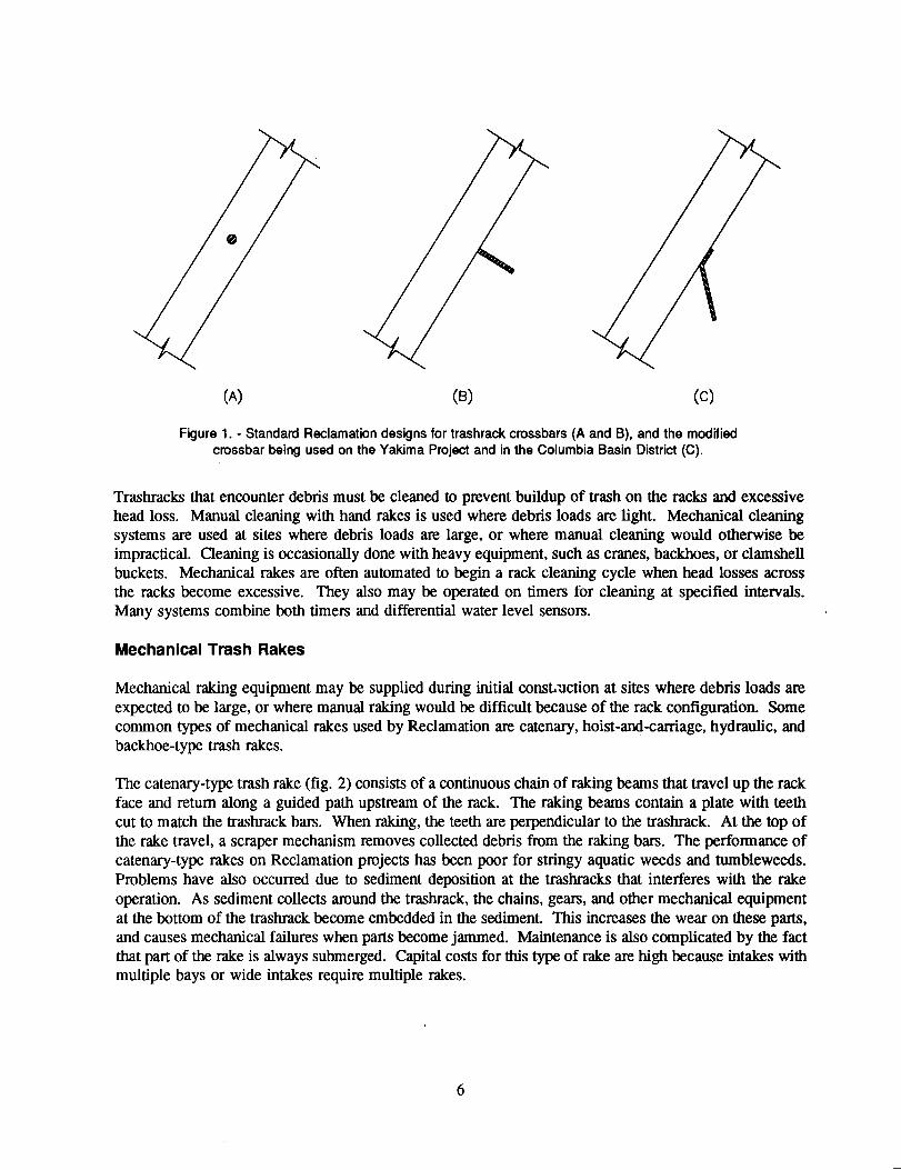
(A) (8) (C)
Figure 1. - Standard Reclamation designs for trashrack crossbars (A and B), and the modifiedcrossbar being used on the Yakima Project and in the Columbia Basin District (C).
Trashracks that encounter debris must be cleaned to prevent buildup of trash on the racks and excessivehead loss. Manual cleaning with hand rakes is used where debris loads are light. Mechanical cleaningsystems are used at sites where debris loads are large, or where manual cleaning would otherwise beimpractical. Qeaning is occasionally done with heavy equipment, such as cranes, backhoes, or clamshellbuckets. Mechanical rakes are often automated to begin a rack cleaning cycle when head losses acrossthe racks become excessive. They also may be operated on timers for cleaning at specified intervals.Many systems combine both timers and differential water level sensors.
Mechanical Trash Rakes
Mechanical raking equipment may be supplied during initial const..uction at sites where debris loads areexpected to be large, or where manual raking would be difficult because of the rack configuration. Somecommon types of mechanical rakes used by Reclamation are catenary, hoist-and-carriage, hydraulic, andbackhoe-type trash rakes.
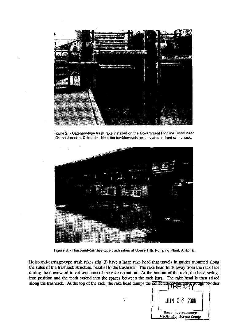
The catenary-type trash rake (fig. 2) consists of a continuous chain of raking beams that travel up the rackface and return along a guided path upstream of the rack. The raking beams contain a plate with teethcut to match the trashrack bars. When raking, the teeth are perpendicular to the trashrack. At the top ofthe rake travel, a scraper mechanism removes collected debris from the raking bars. The performance ofcatenary-type rakes on Reclamation projects has been poor for stringy aquatic weeds and tumbleweeds.Problems have also occurred due to sediment deposition at the trashracks that interferes with the rakeoperation. As sediment collects around the trashrack, the chains, gears, and other mechanical equipmentat the bottom of the trashrack become embedded in the sediment. This increases the wear on these parts,and causes mechanical failures when parts become jammed. Maintenance is also complicated by the factthat part of the rake is always submerged. Capital costs for this type of rake are high because intakes withmultiple bays or wide intakes require multiple rakes.
6
...
Figure 2. - Catenary-type trash rake installed on the Government Highline Canal nearGrand Junction, Colorado. Note the tumbleweeds accumulated in front of the rack.
Figure 3. - Hoist-and-carriage-type trash rakes at Bouse Hills Pumping Plant, Arizona.
Hoist-and-carriage-type trash rakes (fig. 3) have a large rake head that travels in guides mounted alongthe sides of the trashrack structure, parallel to the trashrack. The rake head folds away from the rack faceduring the downward travel sequence of the rake operation. At the bottom of the rack, the head swingsinto position and the teeth extend into the spaces between the rack bars. The rake head is then raisedalong the trashrack. At the top of the rack, the rake head dumps the 0 ec f ther
I .
7GUN 2 8 20;1
Bure&L.i :)j' hec;i.UlStion
Reclamation Service
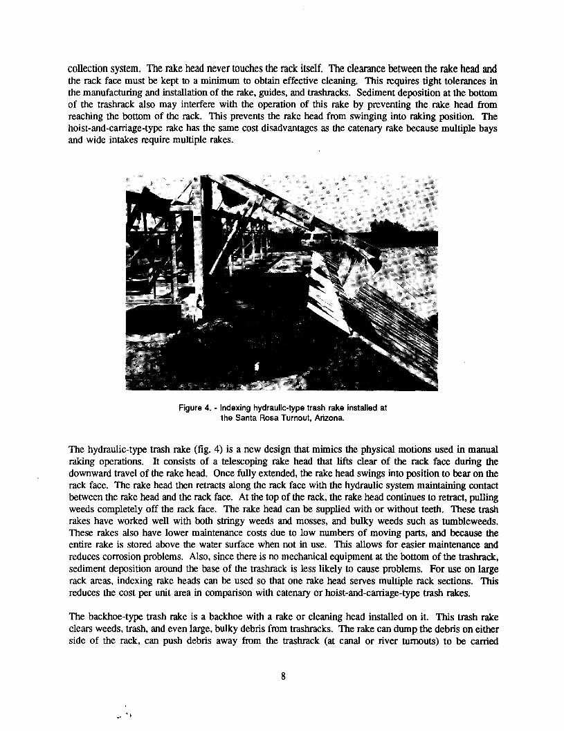
collection system. The rake head never touchesthe rack itself. The clearancebetween the rake head andthe rack face must be kept to a minimum to obtain effective cleaning. This requires tight tolerances inthe manufacturing and installation of the rake, guides, and trashracks. Sediment deposition at the bottomof the trashrack also may interfere with the operation of this rake by preventing the rake head fromreaching the bottom of the rack. This prevents the rake head from swinging into raking position. Thehoist-and-carriage-type rake has the same cost disadvantages as the catenary rake because multiple baysand wide intakes require multiple rakes.
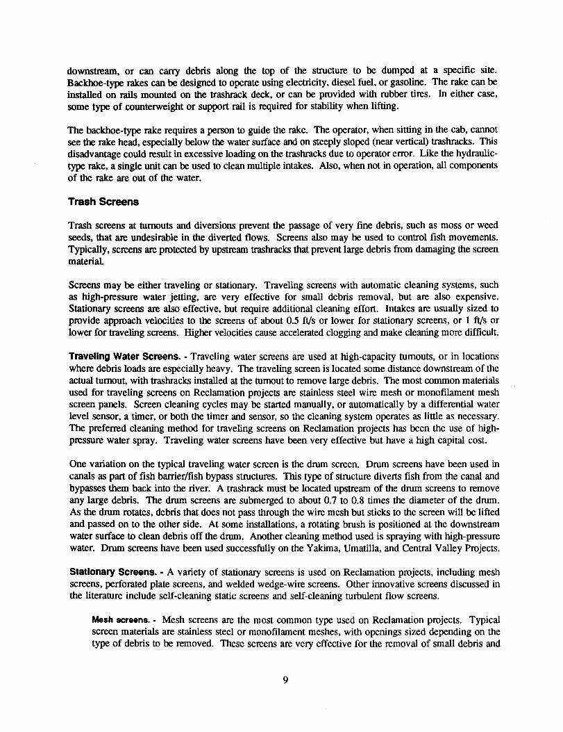
Figure 4. - Indexing hydraulic-type trash rake installed atthe Santa Rosa Turnout, Arizona.
The hydraulic-type trash rake (fig. 4) is a new design that mimics the physical motions used in manualraking operations. It consists of a telescoping rake head that lifts clear of the rack face during thedownward travel of the rake head. Once fully extended, the rake head swings into position to bear on therack face. The rake head then retracts along the rack face with the hydraulic system maintaining contactbetween the rake head and the rack face. At the top of the rack, the rake head continues to retract, pullingweeds completely off the rack face. The rake head can be supplied with or without teeth. These trashrakes have worked well with both stringy weeds and mosses, and bulky weeds such as tumbleweeds.These rakes also have lower maintenance costs due to low numbers of moving parts, and because theentire rake is stored above the water surface when not in use. This allows for easier maintenance andreduces corrosion problems. Also, since there is no mechanical equipment at the bottom of the trashrack,sediment deposition around the base of the trashrack is less likely to cause problems. For use on largerack areas, indexing rake heads can be used so that one rake head serves multiple rack sections. Thisreduces the cost per unit area in comparison with catenary or hoist-and-carriage-type trash rakes.
The backhoe-type trash rake is a backhoe with a rake or cleaning head installed on it. This trash rakeclears weeds, trash, and even large, bulky debris from trashracks. The rake can dump the debris on eitherside of the rack, can push debris away from the trashrack (at canal or river turnouts) to be carried
8
...'-}
downstream, or can carry debris along the top of the structure to be dumped at a specific site.Backhoe-typerakes can be designed to operate using electricity,diesel fuel, or gasoline. The rake can beinstalled on rails mounted on the trashrack deck, or can be provided with rubber tires. In either case,some type of counterweightor support rail is required for stability when lifting.
The backhoe-type rake requires a person to guide the rake. The operator, when sitting in the cab, cannotsee the rake head, especially below the water surface and on steeply sloped (near vertical) trashracks. Thisdisadvantage could result in excessive loading on the trashracks due to operator error. Like the hydraulic-type rake, a single unit can be used to clean multiple intakes. Also, when not in operation, all componentsof the rake are out of the water.
Trash Screens
Trash screens at turnouts and diversions prevent the passage of very fine debris, such as moss or weedseeds, that are undesirable in the diverted flows. Screens also may be used to control fish movements.Typically, screens are protected by upstream trashracks that prevent large debris from damaging the screenmaterial.
Screens may be either traveling or stationary. Traveling screens with automatic cleaning systems, suchas high-pressure water jetting, are very effective for small debris removal, but are also expensive.Stationary screens are also effective, but require additional cleaning effort. Intakes are usually sized toprovide approach velocities to the screens of about 0.5 fils or lower for stationary screens, or I fils orlower for traveling screens. Higher velocities cause accelerated clogging and make cleaning more difficult.
Traveling Water Screens. . Traveling water screens are used at high-capacity turnouts, or in locationswhere debris loads are especially heavy. The traveling screen is located some distance downstream of theactual" turnout, with trashracks installed at the turnout to remove large debris. The most common materialsused for traveling screens on Reclamation projects are stainless steel wire mesh or monofilament meshscreen panels. Screen cleaning cycles may be started manually, or automatically by a differential waterlevel sensor, a timer, or both the timer and sensor, so the cleaning system operates as little as necessary.The preferred cleaning method for traveling screens on Reclamation projects has been the use of high-pressure water spray. Traveling water screens have been very effective but have a high capital cost.
One variation on the typical traveling water screen is the drum screen. Drum screens have been used incanals as part of fish barrier/fish bypass structures. This type of structure diverts fish from the canal andbypasses them back into the river. A trashrack must be located upstream of the drum screens to removeany large debris. The drum screens are submerged to about 0.7 to 0.8 times the diameter of the drum.As the drum rotates, debris that does not pass through the wire mesh but sticks to the screen will be liftedand passed on to the other side. At some installations, a rotating brush is positioned at the downstreamwater surface to clean debris off the drum. Another cleaning method used is spraying with high-pressurewater. Drum screens have been used successfully on the Yakima, Umatilla. and Central Valley Projects.
Stationary Screens. . A variety of stationary screens is used on Reclamationprojects, including meshscreens, perforated plate screens, and weldedwedge-wirescreens. Other innovative screens discussed inthe literature include self-cleaning static screens and self-cleaningturbulent flow screens.
Meshscreens. - Mesh screens are the most common type used on Reclamation projects. Typicalscreen materials are stainless steel or monofilamentmeshes, with openings sized depending on thetype of debris to be removed. These screens are very effective for the removal of small debris and
9

moss-type weeds, but are difficult to clean. Most sites with mesh screens have two sets of screensplaced in series, so that one screen is in place while the other is cleaned. The preferred cleaningmethod for stationary screens is waterjetting. However, at sites without power, screens are usuallydried, then scrubbedwith a stiff brush. Due to the time required for this type of cleaning, additionalsets of screen panels may be required.
Perforated plate screens. . The perforated plate screen consists of a plate with punched orifice holesand was developed to address problems with the common mesh-type screen. Perforated plate screensare well suited to areas with moss, because moss lays on the plate, rather than becoming entangledin the mesh fabric. The open area ratio is usually about 50 percent, and does not vary significantlywith the size of the orifice holes. Manufacturing requirements limit the hole diameter to thethickness of the plate or smaller. Perforated plate screens have been used on the GovernmentHighline Canal, near Grand Junction, Colorado (Haider, 1989). Performance of the perforated platescreens has been good when approach velocities are 0.3 ftls or lower.
Effective cleaning methods for perforated plate include water jetting, manual cleaning with a rubbersqueegee, vacuuming with a swimming pool-type vacuum, or mechanical cleaning by sweeping barswith bristle brushes. On the Government Highline Canal, a squeegee to push the debris to thebottom of the screen panel is the preferred cleaning procedure. Flow parallel to the screen face thencarries the debris on downstream. A vacuum also has been used successfully at this site. The choiceof a specific cleaning method depends on the type and amount of debris and the availability of powerat the site.
Strong and Ott (1989) report tha~ perforated plate screens with mechanical brush cleaning systemshave been used by the CDFG (California Department of Fish & Game) at many sites. However,there are several inherent problems:
. Lack of electric power at remote sites.Icing of mechanical equipment.Oogging by small rocks, leaves, pine needles, or filamentous algae not efficientlyremoved by the brushes.Requirement for bypass flow along the screen face to carry debris downstream after it isswept off the screen by the brushes. This limits the usefulness of perforated plate at dead-end locations.
.
.
.
Some of these screens have been replaced successfully in recent years by the self-cleaning staticscreen described below. The installation cost of perforated plate screens has been estimated at about$150 per ff/s (Strong and Otto 1989).
Karrh (1950) conducted tests to evaluate head loss through a perforated plate fish screen similar tothose used by CDFG. These tests compared the head loss through a 16-gauge, perforated plate with5/32-in-diameter holes staggered on 7/32-in centers, to that through a 19-9auge, galvanized wirescreen with 5/32-in-square openings. These screens have similar sizes of openings and thus providesimilar debris removal capabilities. Tests were conducted with the screens placed perpendicular tothe flow, and at 45° to the flow. With the screens placed perpendicular to the flow, the head lossthrough the perforated plate was 8.5 to 12 times higher than that through the wire mesh screen forthe same discharge and total screen area. When the screens were placed at 45° to the flow, theperforated plate head loss was 5.8 to 8 times higher. The difference in head loss is largely attributedto the difference in the open area ratios of the two screens.
10

Weldedwedge-wirescreens.- Welded wedge-wire screens are constructed of wedge shaped wires,mounted so that the minimum clear space between wires is at the upstream face of the screen. A
FLOW ~
Figure 5. - Sectional view of a welded wedge-wire screen panel.
sectional view of a wedge-wire screen panel is shown in figure 5. Any debris small enough to enterthe upstream face of the screen will pass through without becoming wedged in the screen.Wedge-wire screens are usually constructed of stainless steel to reduce corrosion. For use on intakes,these screens are often built in a circular configuration (passive water screens) similar to a wellscreen, and are usually equipped with an air back-flush system to clean the screens. These screensare often arranged in a tee structure, with two drum screens teed onto a single intake pipe. Wheninstalled on an intake with flow past the screen, these screens are somewhat self-cleaning, and debrisflushed off the screens by the air back-flush system is carried downstream. The intakes to DiamondCreek Pumping Plant at Buffalo Bill Reservoir are currently being fitted with this type of screen.Although the air-burst backflush system will clean the screens, the intakes for this plant are locatedat the end of a dead-end channel, allowing debris to collect over time around the intakes. Collectingand removing debris occasionally from the intake area will be required.
Drum-type welded wedge-wire screens also can be made somewhat self-cleaning by rotating themin a crossing flow. This technique was evaluated in studies for screens required for the proposedPeripheral Canal in California. The tests showed that small debris still accumulated and eventuallyclogged the screen, but larger debris was washed off the screen by the crossing flow.
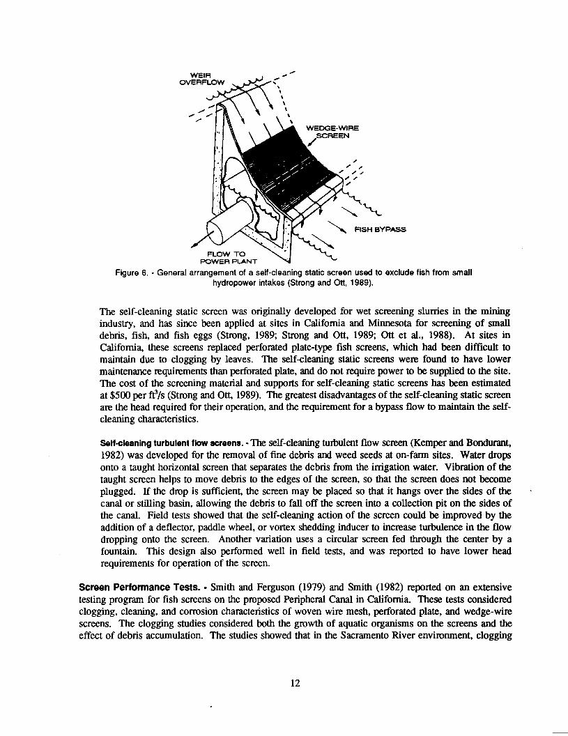
Self-cleaning static screens. - The self-cleaning static screen is an overflow-type screen constructedwith wedge-wire panels. The panels are installed on the downstream face of an overflow weir, asshown in figure 6. A layer of water is sliced off by each wire; the solids continue over the panel,and are deposited in a debris pit or other waterway downstream. If flows are high enough, all debrisis carried off the screen, along with some bypass flow. When bypass flows are lower, debris willaccumulate on the lower portions of the screen. V-notch weirs have been used at some sites tomaintain higher unit discharges at low flows, thus maintaining some bypass flow and a self-cleaningaction over a wide range of flow conditions.
11
FLOW TOPOWER PLANT
Figure 6. - General arrangement of a self-cleaning static screen used to exclude fish from smallhydropower intakes (Strong and Ott, 1989).
FISH BYPASS
The self-cleaning static screen was originally developed for wet screening slurries in the miningindustry, and has since been applied at sites in California and Minnesota for screening of smalldebris, fish, and fish eggs (Strong, 1989; Strong and Ott, 1989; Ott et al., 1988). At sites inCalifornia, these screens replaced perforated plate-type fish screens, which had been difficult tomaintain due to clogging by leaves. The self-cleaning static screens were found to have lowermaintenance requirements than perforated plate, and do not require power to be supplied to the site.The cost of the screening material and supports for self-cleaning static screens has been estimatedat $500 per ff /s (Strong and Ott, 1989). The greatest disadvantages of the self-cleaning static screenare the head required for their operation, and the requirement for a bypass flow to maintain the self-cleaning characteristics.
Self-cleaning turbulent flowscreens. - The self-cleaning turbulent flow screen (Kemper and Bondurant,1982) was developed for the removal of fine debris and weed seeds at on-fann sites. Water dropsonto a taught horizontal screen that separates the debris from the irrigation water. Vibration of thetaught screen helps to move debris to the edges of the screen, so that the screen does not becomeplugged. If the drop is sufficient, the screen may be placed so that it hangs over the sides of thecanal or stilling basin, allowing the debris to fall off the screen into a collection pit on the sides ofthe canal. Field tests showed that the self-cleaning action of the screen could be improved by theaddition of a deflector, paddle wheel, or vortex shedding inducer to increase turbulence in the flowdropping onto the screen. Another variation uses a circular screen fed through the center by afountain. This design also perfonned well in field tests, and was reported to have lower headrequirements for operation of the screen.
ScreenPerfonnanceTests.. Smith and Ferguson (1979) and Smith (1982) reported on an extensivetesting program for fish screens on the proposed Peripheral Canal in California. These tests consideredclogging, cleaning, and corrosion characteristics of woven wire mesh, perforated plate, and wedge-wirescreens. The clogging studies considered both the growth of aquatic organisms on the screens and theeffect of debris accumulation. The studies showed that in the Sacramento River environment, clogging
12

by debris accumulation was the critical factor in detennining the clogging rate. This is in contrast tostudies in salt-water environments in which biofouling was the dominant clogging mechanism.
For screens with similar fish screening efficiency, the perforated plate clogged quickly to a specified levelof head loss. Woven wire mesh screens took about 1.5 times as long to clog to a similar head loss level,while welded wedge-wire screens took 3 times as long to clog as perforated plate. The clogging rate forall screens was affected by the debris concentration in the flows approaching the test screen, and thevelocity nonnal to the screen. Correlations were developed to allow prediction of required cleaningfrequency as a function of Sacramento River discharges. Tests to evaluate the effect of variations in thevelocity component parallel to the screen face showed that the parallel velocity had no significant effecton the clogging rate.
Data were also collected to evaluate the trap efficiency of the tested screens at various levels of clogging.Although one would expect the screens to trap more debris as they become more clogged, in the majorityof tests the trap efficiency decreased as the screens became more clogged. As the screen becomesclogged, the through-hole velocity increases, thus dislodging some material already accumulated on thescreen. The tests did not identify any significant difference in the trap efficiencies of the different screentypes.
Cleaning Options for Trash Screens. . Manual cleaning of stationary screens usually requires removingthe screen. If debris is not tightly woven into the screen material, brushes or squeegees can be used toclean the screen immediately after removing it from the water. When debris is more difficult to remove,screen panels may be left to dry before cleaning. Once dry, scrubbing with a stiff brush will usually breakthe debris loose. In some cases screens may be brushed or cleaned with a squeegee in place.
Numerous mechanical or automatic cleaning options are available depending on the type of screen anddebris: high-pressure water jetting; water or electric-operated bristle brushes or squeegees; portable,swimming pool-type vacuum cleaners; or air burst backflush systems, such as those used on cylindricalwedge-wire screens. The testing program for fish screens on the proposed Peripheral Canal in Californiaevaluated the perfonnance of water jetting and wiper brushes for cleaning of wire mesh, perforated plate,and welded wedge-wire screens (Smith and Ferguson, 1979; Smith, 1982). Wiper brushes were tested outof water only, while water jetting was tested both above water and under water. In these tests, all cleaningmethods worlced well, as measured by residual head loss following the completion of a cleaning cycle.Visually, water jetting with the screens out of water was the most effective.
Two disadvantages of brush cleaning were identified. First, brush cleaning was less effective during thesummer algae season, due to algae buildup on the back side of the screens; water jetting did a better jobof removing algae on the back side of the screen. Second, brush cleaning of woven wire screens wasmore difficult, primarily because the woven wire screen is less rigid than perforated plate or weldedwedge-wire, and sagged away from the brush between supports. The perforated plate and wedge-wirescreens had enough stiffness that good contact was maintained between the brush and screen face.
SURVEY OF RECLAMATION FIELD PROBLEMS
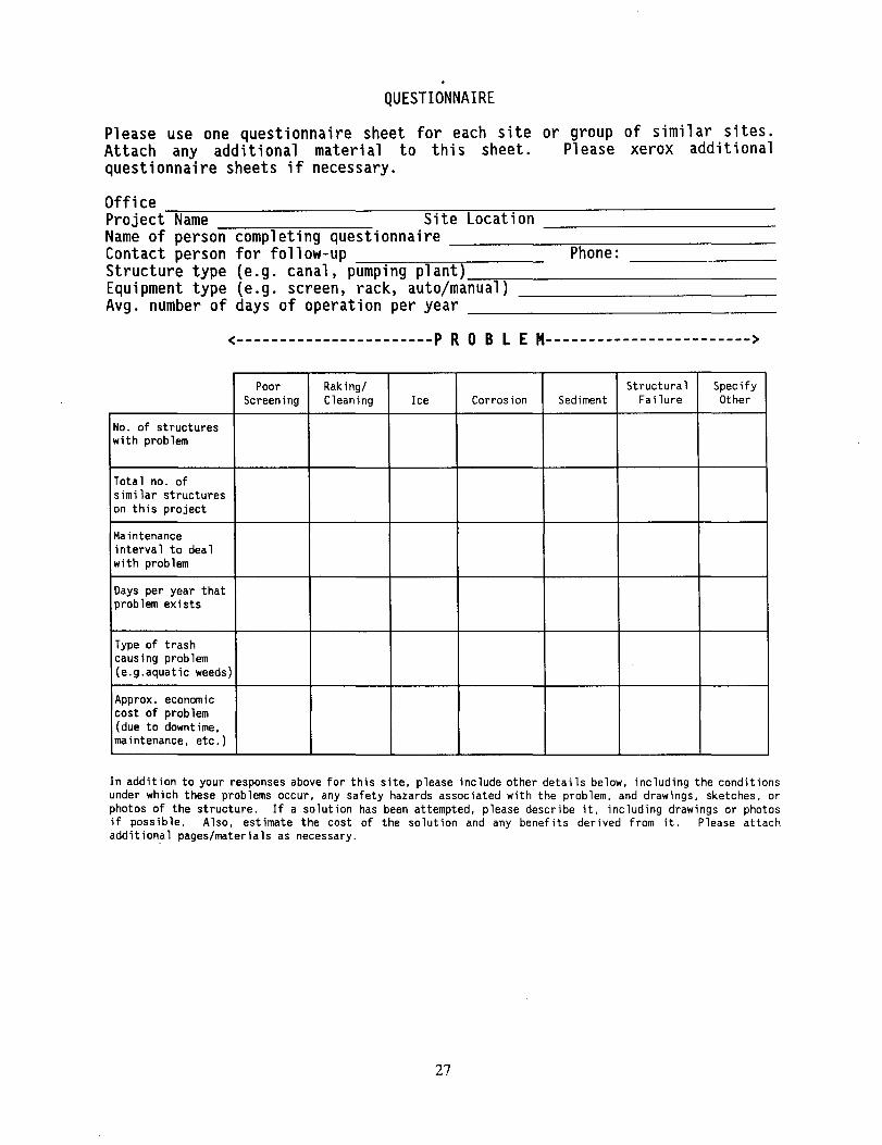
To detennine the most common problems being experienced at Reclamation projects, a one-pagequestionnaire was sent to Reclamation's regional and project offices. Many offices forwarded thequestionnaireto individual irrigationdistricts. A total of 26 offices or irrigationdistricts respondedto the
13
Problems Reported
70
60
50
II!i ~o!'I-0
~30
z20
10
0
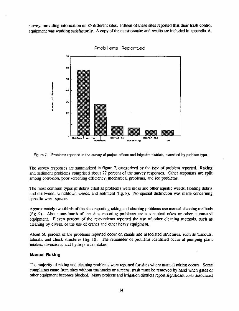
sUivey, providing infonnation on 85 different sites. Fifteen of these sites reported that their trash controlequipment was worldng satisfactorily. A copy of the questionnaire and results are included in appendix A.
Figure 7. - Problems reported in the survey of project offices and irrigation districts, classified by problem type.
The survey responses are summarized in figure 7, categorized by the type of problem reported. Rakingand sediment problems comprised about 77 percent of the survey responses. Other responses are splitamong corrosion, poor screening efficiency, mechanical problems, and ice problems.
The most common types of debris cited as problems were moss and other aquatic weeds, floating debrisand driftwood, windblo~ weeds, and sediment (fig. 8). No special distinction was made concerningspecific weed species.
Approximately two-thirds of the sites reporting raking and cleaning problems use manual cleaning methods(fig. 9). About one-fourth of the sites reporting problems use mechanical rakes or other automatedequipment. Eleven percent of the respondents reported the use of other cleaning methods, such ascleaning by divers, or the use of cranes and other heavy equipment
About 50 percent of the problems reported occur on canals and associated structures, such as turnouts,laterals, and check structures (fig. 10). The remainder of problems identified occur at pumping plantintakes, diversions, and hydropower intakes.
Manual Raking
The majority of raking and cleaning problems were reported for sites where manual raking occurs. Somecomplaints came from sites without trashracks or screens; trash must be removed by hand when gates orother equipment becomes blocked. Many projects and irrigation districts report significant costs associated
14

Debris Types Bt Problem Sites
50
45
5
40
35
'tI.jIitIt
3D
25
20
15
10
0Mo../Aquat.IC We.ds WindBlown-
Float.lngDebris/DrIftwood Sediment
Figure 8. - Types of debris causing problems with trash control equipment.
with manual raking and cleaning, although some projects consider raking and cleaning problems to be nomore than a nuisance. Some projects also noted operational problems caused by excessive trash buildupon the racks. Manual raking may be chosen over mechanical raking systems during the design of a projectfor the following reasons:
. No power available at the siteLimited construction money availableDebris loads and associated O&M costs projected to be low
.
.An example where debris loads were projected to be low is the San Luis Valley Project, Closed BasinDivision, near Alamosa, Colorado. This project pumps ground water from the Closed Basin for use insatisfying downstream water rights on the Rio Grande River. An extensive netwOIx of shallow wellsdelivers water through closed conduit laterals into a main conveyance channel that eventually dischargesinto the Rio Grande. Flows are also diverted from the conveyance channel into nearby San Luis Lake andinto nearby wetlands. The project is being constructed in phases, and is in the fourth of five phases ofdevelopment. Flow rates in the conveyance channel are currently well below the final design flows. Thishas caused excessive weed growth in the canal system, creating severe problems at check structures andturnouts that are primarily manually cleaned. The conveyance channel is constructed with a geomembraneliner to prevent seepage losses from the conveyance channel back into the shallow aquifer. High ground-water levels prohibit the dewatering of the conveyance channel, because excessive uplift pressures wouldfail the canal liner." The inability to dewater the canal is believed to have increased the weed growthproblems. Also, control of weed growth by chemical means is restricted because of the use of the waterin the nearby wetlands. The project is currently testing the use of grass carp for weed control.
15

Cleaning Equipment at Problem Sites
<40
35
30
i
jI~ti
25
20
15
10
5
0Hand Rake.. MeehanI ca I Rakes lotlacel Ianeous
Figure 9. - Cleaning equipment in use at sites reporting problems.
Structures Associated with Problems
35
30
25
'tI.
+'L.
&~I
20
151>0ti
10
5
0Cana 1/ Latera IITlTnout
P"",,Ing StatIon
Figure 1o. - Types of structures at which problems were reported with trash control equipmentin the survey of project offices and irrigation districts.
16
Mechanical Raking
Several projects reported problems with mechanical raking equipment, either due to ineffective operation,or persistent mechanical problems with the equipment. The CAP has reported problems with catenary-typeand hoist-and-carriage type rakes. These rakes have performed poorly with stringy aquatic weeds, andhave also suffered from persistent mechanical problems.
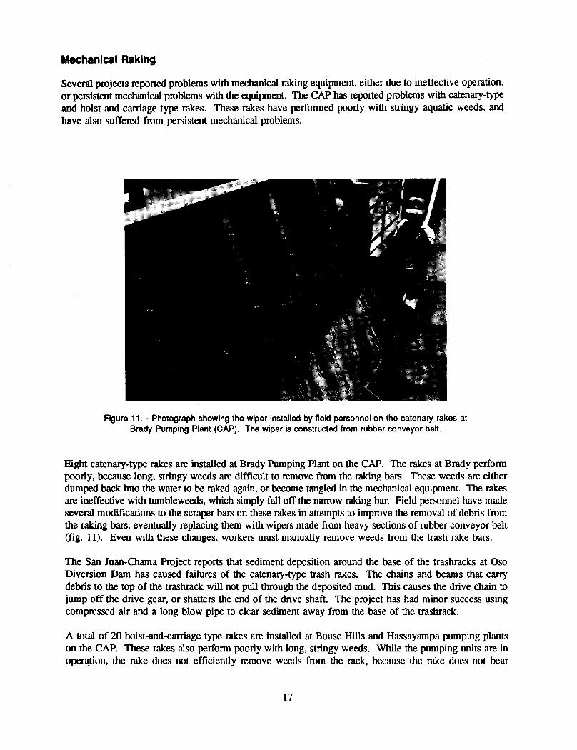
Figure 11. . Photograph showing the wiper installed by field personnel on the catenary rakes atBrady Pumping Plant (CAP). The wiper is constructed from rubber conveyor belt.
Eight catenary-type rakes are installed at Brady Pumping Plant on the CAP. The rakes at Brady performpoorly, because long, stringy weeds are difficult to remove from the raking bars. These weeds are eitherdumped back into the water to be raked again, or become tangled in the mechanical equipment. The rakesare ineffective with tumbleweeds, which simply fall off the narrow raking bar. Field personnel have madeseveral modifications to the scraper bars on these rakes in attempts to improve the removal of debris fromthe raking bars, eventually replacing them with wipers made from heavy sections of rubber conveyor belt(fig. 11). Even with these changes, workers must manually remove weeds from the trash rake bars.
The San Juan-Chama Project reports that sediment deposition around the base of the trashracks at OsoDiversion Dam has caused failures of the catenary-type trash rakes. The chains and beams that carrydebris to the top of the trashrack will not pull through the deposited mud. This causes the drive chain tojump off the drive gear, or shatters the end of the drive shaft. The project has had minor success usingcompressed air and a long blow pipe to clear sediment away from the base of the trashrack.
A total of 20 hoist-and-carriage type rakes are installed at Bouse Hills and Hassayampa pumping plantson the CAP. These rakes also perform poorly with long, stringy weeds. While the pumping units are inoper(\tion, the rake does not efficiently remove weeds from the rack, because the rake does not bear
17

directly on the rack face. Also, the long stringy weeds that are collected by the rake head often fall backinto the water, rather than into the collection trough. This is partially due to the clearance between therake teeth and the concrete headwall, which allows the weeds to fall or be pulled between the headwalland the rake teeth as the rake moves up the headwall. At Hassayampa the rake operation is also hinderedby sediment buildup around the bottom of the racks. This sediment buildup prevents the rake head fromtraveling to the bottom of the rack, thus preventing the rake head from swinging into the raking position.
The CAP has also experienced a variety of mechanical problems with both catenary and hoist-and-carriagetype rakes, including problems with hoist cables, drive motor alignment, and limit switch operation. Fieldpersonnel have solved many of these problems.
One type of mechanical trash rake that has been used successfullyat many Reclamation projects is thehydraulic-typerake. Nearly all surveyresponsesconcerninghydraulic-typetrash rakes indicatedthat theyare working well. The only significant problem with a hydraulic-type rake was reported by the GrandCoulee Project Hydroelectric Authority for a rake installed on the intakes to Smith Powerplant. Heavycross currents caused large deflections of the boom and rake head. A heavier duty model is nowperforming satisfactorily.
The hydraulic-type rake is now the only type of rake being specified for new construction on Reclamationprojects. Hydraulic-type rakes have also successfully replaced older style mechanical rakes and have beenused to upgrade installations that were previously raked by hand. The CAP has successfully modified twotrashrack structures by using hydraulic-type rakes. A small, nonindexing, hydraulic rake was installed atthe Harquahala Valley Irrigation District turnout, and the Santa Rosa turnout, which was originallydesigned to be manually raked, was retrofitted with a large, indexing rake. The PG&E (pacific Gas &Electric Company) has recently retrofitted four installations with hydraulic-type rakes (Stutsman et al.,1989). The Grand Coulee Project Hydroelectric Authority has also successfully retrofitted several sitesusing indexing and nonindexing hydraulic-type rakes.
Screening Effectiveness
Some respondents indicated that poor screening of mossy weeds and algae is a problem. Passage of mossand algae can cause problems with downstream equipment such as gates, valves, and flowmeters. Themajority of sites reporting this type of problem were only using trashracks to catch the debris. The YumaDesalting Plant is experiencing severe problems; a rope-type algae passes through the 2-in bar spacing ofthe intake trashracks or wraps around the rack bars, especially when the upstream irrigators clean thecanals. This algae completely clogs the pretreatment system of the plant. Traveling water screens arepresently being added to these intakes.
Effective debris removal can be achieved in most cases by reducing the bar spacing, or adding screenswith small openings. However, this will increase the amount of debris that must be handled. Suchmodifications should be planned carefully so that debris loads are accurately estimated, and operation andmaintenance costs associated with the modifications are anticipated.
Ice Problems
Ice problems identified in the sUIVeyranged from clogging of trashracks due to frazil ice collecting onrack bars, to icing of exposed portions of mechanical rakes and traveling screens. Burgi and Johnson(1971) provided an extensive review of the ice formation process and Reclamation experiences with iceproblems. Through the efforts of Reclamation's Ice Research Management Committee, extensive research
18
has been conducted on ice control using ice booms (Burgi, 1971; Hayes, 1974). Effective control of iceproblems can also be obtained using bubblers or heating of trashracks and screens (Logan, 1974).
One design feature that helps reduce icing problems is using discontinuous trashrack bars. At sites wheretrashrack bars must extend above the water surface, the upper portions of the bars are separated from thelower bars by a gap or a section of material having poor heat transfer properties. This prevents the lossof heat energy from the lower bars during periods of extreme cold above the water surface.
The San Luis Valley Project, Dosed Basin Division, recently experienced ice problems on a set of racksinstalled to prevent migration of grass carp out of the project canals into the Rio Grande River. The rackswere constructed from small diameter steel water pipe, and were initially installed before grass carpintroduction, to verify that they could be maintained during the winter. Ice buildup completely cloggedthe racks, and they had to be removed from the canals. The next winter the racks were fitted withresistance heating elements placed inside the rack bars. This system has now been in use through onewinter season and has kept the racks free of ice during that time.
Two new approaches to frazil ice control are the use of ice-phobic coating materials and the vibration oftrashracks to remove and prevent ice accumulations. Mussalli et al. (1987) conducted tests of frazil iceclogging of trashracks in a refrigerated flume. These tests combined the use of coatings and rackvibration. The tests showed that vibration levels of 15 g for a duration of 1 to 3 minutes were sufficientto both break ice loose, and prevent adherence of ice to coated or uncoated trashracks. The use of apolyamine, 2-part 100 percent epoxy coating also reduced the rate of ice buildup on the rack, anddecreased the vibration duration to dislodge ice from the rack. Unfortunately, vibrations of this magnitudemay lead to early structural failure of the trashrack, and ice-resistant coatings are easily damaged by debrisand cleaning equipment.
Heating of trashracks and screens remain the most effective technique for preventing frazil iceaccumulations. Recent research on the frazil ice accumulation process shows that frazil ice firstaccumulates on the leading edge of trashrack bars. Thus, one need only heat the leading edge of the barsto eliminate frazil ice accumulations. This promises to greatly reduce the power requirements for trashrackheating systems (Daly et al., 1990).
Corrosion
A small number of the survey respondents expressed concern with corrosion. Oversizing components toallow for corrosion has been the typical practice in the past for design of trashracks on Reclamationprojects. The use of corrosion resistant materials or other special protective measures has generally notbeen economical. Most projects responding to the survey with corrosion concerns have an active programof preventive maintenance to minimize problems due to corrosion. The use of sacrificial anodes orimpressed currents can greatly reduce corrosion problems. Development of trashracks and trash screensusing materials such as stainless steel, plastics, or special protective coatings may help further reducecorrosion problems. Special coatings also may help to reduce problems due to frazil ice as discussedabove.
The tests for California's proposed Peripheral Canal included a series of corrosion tests of possible fishscreen materials (Smith and Ferguson, 1979; Smith, 1982). Corrosion tests were conducted on perforatedplate, wire mesh, and welded wedge-wire screens constructed from mild steel, weathering steel, severaltypes of stainless steel, and two types of aluminum. Algaecide and enamel coatings were tested on mildsteel samples, and the aluminum samples were tested with and without protective seal coatings. No other
19

corrosion prevention measures were used. Samples were tested over a 4-year period in an environmentsimilar to the location at which the fish screens would be installed. Perforated plate and weldedwedge-wire screens constructed from type 304 stainless steel showed no evidence of corrosion during thetest period. Woven wire mesh screens of type 304 stainless steel showed slight corrosion, as did screensconstructed from other types of stainless steel. Coatings applied to the mild steel samples slowed thecorrosion rate initially, but were ineffective in the long term. Bubbles and fractures in the coatingsallowed corrosion to occur, especially at the edges of holes in the perforated plate, and at locations wherethe wire mesh screens were scratched from handling. The aluminum screens pitted badly and accumulateddeposits of aluminum oxide in the screen holes, which were difficult to remove. The uncoated mild steeland weathering steel samples corroded so badly that the samples were lost.
Sediment Deposition
Several projects reported sediment problems affecting the operation of trash raking equipment. One typeof trash rake particularly prone to problems with sediment was the hoist-and-carriage type rake. This rake,described previously, has a rake head that swings into position at the bottom of the rack panel. Thisaction is triggered when the rake head reaches the bottom of its travel and engages a trip mechanism. Assediment builds up in the region of the trashrack, the rake head is prevented from traveling to the bottomof the rack, and never reaches the trip mechanism. Other trash rake designs with mechanical componentslocated at the bottom of the trashrack are also susceptible to sediment problems.
In addition to detrimental effects on the trash rake, sediment accumulating around the intakes also mayreduce the capacity and efficiency of the intake and cause other operational problems. The majority ofprojects reporting sediment problems deal with those problems only on an annual basis. During thenonirrigation season sediment deposits can be easily removed. For many structures the costs associatedwith this annual maintenance are minimal. Higher maintenance costs are incurred if sediment must beremoved during canal operation, or if sediment must be removed from a large portion of the distributionsystem.
Changing the geometry of intakes or the flow channel to control the location of sediment deposition canhelp alleviate sediment problems. Vanes installed on the channel bed can be useful in this regard(Odgaard and Wang, 1991a, 1991b). Often, successful modifications require detailed hydraulic and/orcomputer model studies. Studies conducted during the initial design stage can help to avert futuresediment problems, especially when the potential for sediment problems has already been identified.
Preventing the passage of fme sediments through trashracks or screens is infeasible due to the fme screensizes and large intake areas required. Larger gravels and cobbles may be controlled by appropriatelydesigned racks or screens, but present a disposal problem. Often, accumulated sediment can be bypasseddownstream periodically through a sluiceway. However, the San Juan-Chama Project reported severesediment problems despite the presence of a sluiceway. On this project, public concerns over sedimentreleases have prevented the use of the sluiceways, causing massive sediment accumulations behind 080,Blanco, and Little 080 diversion dams. These sediment accumulations regularly plug the manually rakedtrashracks on the project, and interfere with the operation of automatic rakes.
Sedimentation basins are another alternative for sediment control. The size of the basin required isdependent on the flow, sediment quantity, and particle sizes. Periodic cleaning of the basins is required.This may be accomplished by a dredge or by draining the basin and then using a bobcat or front-endloader.
20
BIBLIOGRAPHY
Baca. L., "Study on Head Loss for Headworks at the Tehama-Colusa Canal," Memorandum to Head,Hydraulic Research Section, Bureau of Reclamation, Denver, CO, September 10, 1981.
Bureau of Reclamation, "Trashrack Rake Modification," Operation and Maintenance Equipment andProcedures, Denver, CO, September-October 1953.
Bureau of Reclamation, "Weed Conpul and' Removal Equipment," Irrigation O&M Bulletin, No. 69,Denver, CO, July-September 1969. .
Bureau of Reclamation, "Pumping Plant Trashrack," Irrigation O&M Bulletin, No. 69, Denver, CO, July-September 1969.
Bureau of Reclamation, "Mechanical Trashrack," Irrigation O&M Bulletin, No. 69, Denver, CO, July-September 1969.
Bureau of Reclamation, "Pivotal Trashrack on the Charles Hansen Feeder Canal," Water O&M Bulletin,No. 121, Denver, CO, September 1982.
Bureau of Reclamation, "Corrosion Problem on Trash Screen," Water O&M Bulletin, No. 121, Denver,CO, September 1982.
Bureau of Reclamation, Design of Small Dams, 3rd ed., Denver, CO, 1987.
Burgi, P. H., Ice Control Structure on the North Platte River - A Hydraulic Model Study, Report No.REC-ERC-7l-46, U.S. Bureau of Reclamation, Denver, CO, December 1971.
Chow, V. T., Open-Channel Hydraulics, McGraw-Hill Book Co., New York, 1959.
Creager, W. P., and 1. D. Justin, Hydroelectric Handbook, 2nd ed., John Wiley & Sons, Inc., New York,NY, 1950.
Daly, S. F., F. D. Haynes, D. Garfield, and J. G. Gagnon, "Laboratory Investigation of Trashrack Heatingto Prevent Freezeup by Frazil Ice," Proceedings of the 10th International Symposium on Ice, InternationalAssociation for Hydraulic Research, Espoo, Finland, August 20-23, 1990.
Haider, T. R., "Current Screening Systems Used by the Bureau of Reclamation on lITigation Canal TurnoutStructures, With Emphasis on Perforated Plate," 2nd International Symposium on Design of HydraulicStructures, Fort Collins, CO, 1989.
Hanson, B. N., W. H. Bason, B. E. Beitz, and K. E. Charles, Studies of Profile Wire Screen as SurfaceWater Intakes, Ichthyological Associates, Inc., Ithaca, NY, July 1978.
Hansson, H., "Method and a Device for Automatic Qeaning of Trashracks at Water Intakes for WaterPower Plants and Similar," U.S. Patent No. 4,218,319, August 19, 1980.
Hayes, R. B., Design and Operation of Shallow River Diversions in Cold Regions, Report No. REC-ERC-74-19, U.S. Bureau of Reclamation, Denver, CO, 1974.
21

Hopping, P. N., D. M. Gatten, and D. P. Houston, "Physical Model of a Floating Trash Boom to ControlAquatic Weeds at the TVA Widows Creek Fossil Plant," Hydraulic Engineering, Proceedings, 1991National Conference on Hydraulic Engineering, Nashville, TN, July 29-August 2, 1991.
Humpherys, A., "New Innovations in Trash Screens Increase Canal Efficiency," Water O&M Bulletin, No.129, U.S. Bureau of Reclamation, Denver, CO, September 1984.
Kan'h, W. 1., Fish Screen Head Loss--Perforated 16-Gage Steel Plate Versus 5-Mesh, 19-Gage GalvanizedWire--Tracy Pumping Plant Intake--Central Valley Project, Hydraulics Laboratory Report No. Hyd-274,U.S. Bureau of Reclamation, Denver, CO, March 1950.
Kemper, W. D., and J. A. Bondurant, "Turbulent Flow Self Oeaning Trash Screens," The IrrigationAssociation,Technical ConferenceProceedings,pp. 75-84, 1982.
Logan, T. H., Prevention of Frazillce Clogging of Water Intakes by Application of Heat, Report No.REC-ERC-74-l5, U.S. Bureau of Reclamation, Denver, CO, 1974.
Mussalli, Y.G., L. S. Gordon, and S. F. Daly, "Frazil Ice Control Using Electromechanical Vibrators andIce-Resistant Coatings," Waterpower' 87, Proceedings, International Conference on Hydropower, Portland,,OR, August 19-21, 1987.
Odgaard, A. J., and Y. Wang, "Sediment Management with Submerged Vanes. I: Theory," Journal ofHydraulic Engineering, vol. 117, No.3, pp. 267-283, March 1991.
Odgaard, A. J., and Y. Wang, "Sediment Management with Submerged Vanes. II: Applications," Journalof Hydraulic Engineering, vol. 117, No.3, pp. 284-302, March 1991.
Odinets, Y. S., "Monitoring the Oogging of Hydrostation Trashracks," Hydrotechnical Construction,vol. 22, No.8, pp. 497-498, February 1989.
Orsborn, J. F., "Rectangular Bar Trashrack and Baffle Headlosses," Journal of the Power Division,American Society of Civil Engineers, pp. 111-123, 1968.
Ott, R. F., E. Boersma, and 1. J. Strong, "Innovative Static Self-Oeaning Intake Screen Protects BothAquatic Life and Turbine Equipment," Proceedings, Fish Protection at Steam and Hydroelectric PowerPlants, EPRI CSIEN AP-5663-SR, March 1988.
Perham, R. E., "Some Economic Benefits of Ice Booms," Proceedings, Second International Symposiumon Cold Regions Engineering, Fairbanks, AK, August 12-14, 1976.
Perham, R. E., "Floating Debris Control Systems for Hydroelectric Plant Intakes," The REMR Bulletin,U.S. Anny Corps of Engineers, vol. 3, No.2, September 1986.
Peterka, A. 1., Hydraulic Model Tests on the Moss Prevention Devices for the Friant-Kern Canal,Hydraulics Laboratory Report No. Hyd-351, U.S. Bureau of Reclamation, Denver, CO, May 1952.
Smith, L. W., and D. A. Ferguson, Progress Report on Clogging, Cleaning, and Corrosion Studies ofPossible Fish Screens for the Proposed Peripheral Canal, California Department of Water Resources,87 pp., October 1979.
22

Smith, L. W., Clogging, Cleaning, and Corrosion Studies of Possible Fish Screens for the ProposedPeripheral Canal, California Department of Water Resources, Technical Report I, No.FFIENG-4ATR/82-1, 64 pp., September 1982.
Spangler, 1., "Investigations of the Loss Through Trashracks Inclined Obliquely to the Stream Flow,"Hydraulics Laboratory Practice, American Society of Mechanical Engineers, p. 461, 1929.
Strong, J. J., and R. F. On, "Intake Screens for Small Hydro Plants," SHP News, No.4, 1989.
Strong, J., "Innovative Fish Barrier for Waterfowl Lake Restoration," Proceedings, Association ofConservation Engineers, Lexington, KY, October 1989.
Stutsman, R. D., G. D. Mackey, and 1. J. Strong, "Upgrading Trashraking Equipment During ScheduledMaintenance Outages," Waterpower '89, Proceedings, International Conference on Hydropower, NiagaraFalls, NY, 10 pp., August 23-25, 1989.
Swaminathan, K. V., "Design of Trashracks," Indian Journal of Power and River Valley Development, pp.155-167, 1963.
U.S. Anny Corps of Engineers, "Open Channel Flow Trashrack Losses," Hydraulic Design Criteria, sheet010-7.
Wahl, T. L., Investigation of Debris and Safety Boom Alternatives for Reclamation Use, ReportNo. R-92-04, U.S. Bureau of Reclamation, Denver, CO, 1992.
Yeh, H. H., and M. Shrestha, "Free-Surface Flow Through Screen," Journal of Hydraulic Engineering,Vol. 115, No. 10, pp. 1371-1385, October 1989.
23

.
APPENDIX
Questionnaire and results
25

Poor Raking/ Structural SpecifyScreening Cleaning Ice Corrosion Sediment Failure Other
No. of structureswith problem
Total no. ofsimilar structureson this project
Maintenanceinterval to dealwith problem
Days per year thatproblem exists
Type of trashcausing problem(e.g.aquatic weeds)
Approx. economiccost of problem(due to downtime,maintenance, etc.)
QUESTIONNAIRE
Please use one questionnaire sheet for each site or group of similar sites.Attach any additional material to this sheet. Please xerox additionalquestionnaire sheets if necessary.
OfficeProject Name Site LocationName of person completing questionnaireContact person for follow-upStructure type (e.g. canal, pumping plant)Equipment type (e.g. screen, rack, auto/manual)Avg. number of days of operation per year
Phone:
< p ROB L E M >
In addition to your responses above for this site, please include other details below, including the conditionsunder which these problems occur, any safety hazards associated with the problem, and drawings. sketches. orphotos of the structure. If a solution has been attempted. please describe it, including drawings or photosif possible. Also, estimate the cost of the solution and any benefits derived from it. Please attachadditional pages/materials as necessary.
27
x XX XX XX XX XX XXx XX
XX XX X XX XX XXX
XXX
XXx X
x = PrQblem Reported0 = No ProblemF = Problem Fixed
Survey Results
PROBLEM------------------------------------
DEBRIS
WindRake/ Poor Float Aqua. Blown DriftClean Screen Corr. Mech. Ice Sed. None Trash Moss Weeds Weeds wood Ice Sed.
------------------------------------GP, North Platte R. PO
8 Kendrick9 Goshen ID
10 Gering-Ft. Laramie11 Pathfinder ID12 Mitchell ID13 Farmers ID14 Farmers ID15 Northport ID16 Northport ID17 All ID's18 Kendrick-Alcova Res.19 Guernsey Dam20 Whalen Div. Dam21 Pathfinder ID22 Mitchell ID23 Farmers ID
X XXXXXX
XXXXXXXX
XXXXXXXXX
X
X
XXXX
XXXXXX
X
XX
30 GP, Bostwick ID, Nebr.------------------------------------
XX------------------------------------
GP, Belle Fourche PO33 South Canal34 North Canal
XX
X X XX
------------------------------------GP, Bighorn Basin PO
41 Highland Hanover ID42 Upper Bluff ID
XX
Xx
X
------------------------------------GP, Montana PO
64 Canyon Ferry Proj.65 Canyon Ferry Power Pl.
X X X X X X X0
------------------------------------GP, Montana PO
72 Huntley73 Yellowtail Dam
X X X X X X0
77 GP, Missouri-Souris------------------------------------
XX
------------------------------------GP, Shosh-Heart Mt. ID
78 Garland Power Plant79 Eaglenest Spillway80 Bitter Creek pickup81 Bauee drain pickup82 Alkali pickup
XXX
00 0
XX X
XXX
------------------------------------UC, Grand Junction PO
4 Grand Valley5 Paonia6 Uncompahgre7 Collbran
XXXX
X
X
X XXX X
X X
29 UC, Flaming Gorge------------------------------------
XX------------------------------------
UC, San Luis Valley31 Franklin Eddy Canal32 San Luis Lake
XX
X XX
X XX
X XX
------------------------------------
28
x = Problem Reported0 = No ProblemF = Problem Fixed
Survey Results fcontinuedn
PROBLEM DEBRIS------------------------------------
WindRake/ Poor Float Aqua. Blown DriftClean Screen Corr. Mech. Ice Sed. None Trash Moss Weeds Weeds wood Ice Sed.
------------------------------------UC, NAPI-Farmington,NM
43 Canals44 Turnouts45 Pumping Plant
x x
x
xxX X
XX
X
------------------------------------UC, Durango PO
68 Florida69 Hammond70 Mancos71 Dolores
X
XX
X0
XX
XXXX X
2 PN, Grand Coulee PO------------------------------------
XBoomdeterioration------------------------------------
3 PN, Grand Coulee PO X------------------------------------
X28 PN, Minidoka-Palisades X------------------------------------
XPN, Minidoka PO
66 Ririe Flood Channel67 Minidoka Dam
XX X
XX
------------------------------------X
PN, Grand Coulee Proj.Hydro Authority
74 PEC 66.0 Power Plant75 Smith Power Plant76 EBC4.6 Power Plant
FFF
F000
FFF
FFF
1 MP, Klamath Proj.------------------------------------
0------------------------------------
MP, Tracy Office (CVP)24 Fish Facility25 New Melones26 Tracy Pump Plant27 O'Neill Pump Plant
X X X XX
X
X
X
------------------------------------
X0
MP, Fresno Office35 San Luis & Coalinga36 Pleasant Valley
X X
X
46 MP, Folsom Office(CVP)------------------------------------
X
0
XX
X
X------------------------------------
MP, Shasta Offlce(CVP)47 Shasta Dam48 Keswick Dam49 Clear Cr. Tunnel50 Lewiston Dam51 Spring Cr. Debris Dam52 Keswick Power Plant
X
XXXXXX
X XXX X
X
X
------------------------------------
XX
LC, Arizona PO37 Havasu Pump Plant38 Bouse Hills & other39 Brady, Red Rock, other40HVID, Santa Rosa
0XX
X X XX
XX
X
------------------------------------
XX0
29
x X X X Xx Xx X X XX X X XX X X XX Xx X Xx X X
X X X X Xx X X X X Xx X X X X X
-------------------------------------- ------------------------------------58 7 8 5 5 28 0 20 18 25 31 19 5 28
0 0 0 0 0 0 15 1 0 0 1 0 0 03 0 0 1 0 0 0 0 0 3 3 0 0 0
x = Problem Reported0 = No ProblemF = Problem Fixed
Survey Results fcontinuedl
PROBLEM DEBRIS------------------------------------
WindRake/ Poor Float Aqua. Blown DriftClean Screen Corr. Mech. Ice Sed. None Trash Moss Weeds Weeds wood Ice Sed.
------------------------------------LC. Yuma PO
56 Coachella57 Wellton-Mohawk I&DD58 Canals59 Major pump stations60 Mid-size pump stations61 Gila Project62 Gila Canal63 South Gila Canal
------------------------------------UC. San Juan-Chama PO
83 Little Oso Div. Dam84 Oso Diversion Dam85 Blanco Diversion Dam-------------------------
Total With ProblemsTotal With No ProblemTotal W/Problem Fixed
------------------------------------------------------------------------------------------------------------------------------------------------------------------------------------------------------------
30

x X XX X XX X XX X XX X XX X XX X Xx X XX X XX Xx X XX X X
X XX X X
X XX X X
x = Problem Reported0 = NoProblemF = Problem Fixed
EQUIPMENT STRUCTURE
-----------------------------------------RAKE
---------------------
-----------------------------------------
Fixed Trav. Trash Hand Auto Hydr Heavy Lat- Turn- Pump Power Oiver-None Boom Screen Screen Rack Raked Rake Rake Equip Canal eral out Siphon Sta. Intake sion
GP, North Platte R. PO8 Kendrick9 Goshen 10
10 Gering-Ft. Laramie11 Pathfinder 1012 Mitchell ID13 Farmers 1014 Farmers 1015 Northport 1016 Northport 1017 All IO's18 Kendrick-Alcova Res.19 Guernsey Dam20 Whalen Oiv. Dam21 Pathfinder 1022 Mitchell 1023 Farmers ID
30 GP, Bostwick 10, Nebr.-----------------------------------------
XX XX-----------------------------------------
GP, Belle Fourche PO33 South Canal34 North Canal
XX
XX
XX
XX
-----------------------------------------GP, Bighorn Basin PO
41 Highland Hanover 1042 Upper Bluff 10
XX
XX
XX
-----------------------------------------GP. Montana PO
64 Canyon Ferry Proj.65 Canyon Ferry Power Pl.
X0
X X0
-----------------------------------------GP, Montana PO
72 Huntley73 Yellowtail Dam
X X
77 GP. Missouri-Souris-----------------------------------------
XX X
-----------------------------------------GP, Shosh-Heart Mt. 10
78 Garland Power Plant79 Eaglenest Spillway80 Bitter Creek pickup81 Bauee drain pickup82 Alkali pickup
00 0
XX
XXXX X
-----------------------------------------UC, Grand Junction PO
4 Grand Valley5 Paonia6 Uncompahgre7 Collbran
X XXXX
xXXXX
X X X
29 UC. Flaming Gorge-----------------------------------------
XX-----------------------------------------
UC, San Luis Valley31 Franklin Eddy Canal32 San Luis Lake
X X X XX X
-----------------------------------------
31
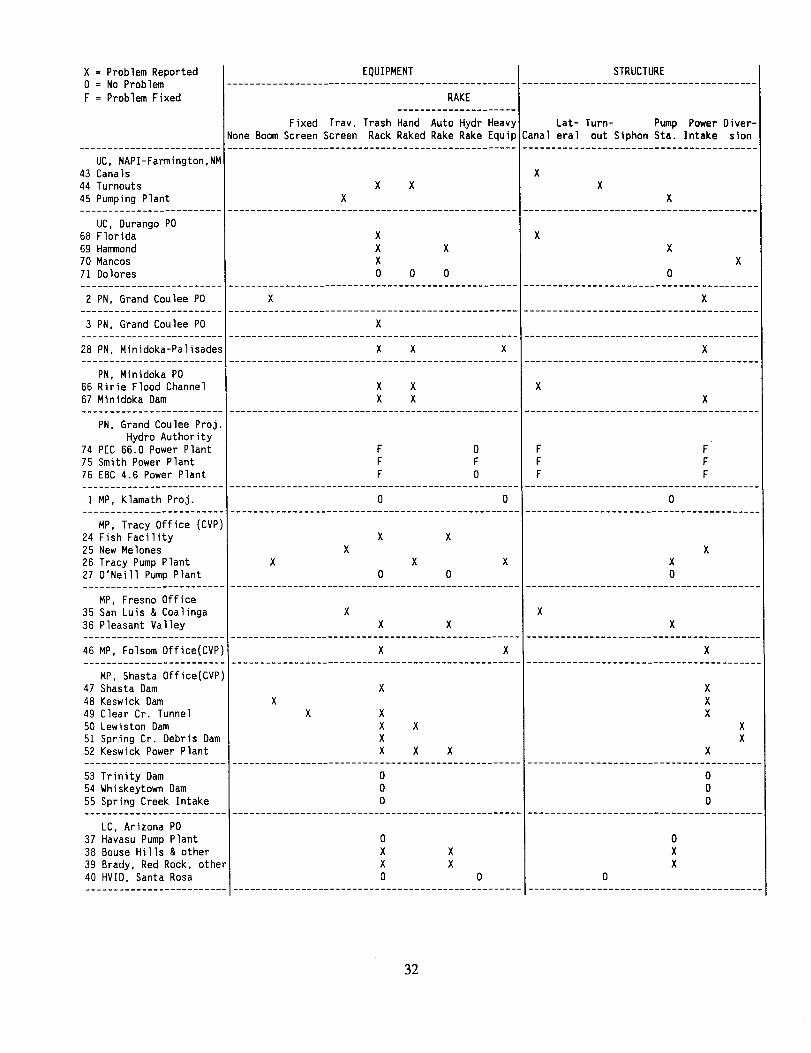
PN, Grand Coulee Proj.Hydro Authority
74 PEC 66.0 Power Plant F 0 F F75 Smith Power Plant F F F F76 EBC4.6 Power Plant F 0 F F
Xx
X XX XXX X X
x = Problem Reported0 = NoProblemF = Problem Fixed
EQUIPMENT STRUCTURE
-----------------------------------------RAKE
---------------------Fixed Trav. Trash Hand Auto Hydr Heavy Lat- Turn- Pump Power Diver-
None BoomScreen Screen Rack Raked Rake Rake Equip Canal eral out Siphon Sta. Intake sion-----------------------------------------
UC, NAPI-Farmington,NM43 Canals44 Turnouts45 Pumping Plant
xx x x
x x-----------------------------------------
UC, Durango PO68 Florida69 Hammond
70 Mancos71 Dolores
xXX0
XX X
X0 0 0
-----------------------------------------2 PN, Grand Coulee PO X X
-----------------------------------------3 PN, Grand Coulee PO X
-----------------------------------------28 PN, Minidoka-Palisades X X X X
-----------------------------------------PN, Minidoka PO
66 Ririe Flood Channel67 Minidoka Dam
XX
XX
XX
-----------------------------------------
-----------------------------------------1 MP, Klamath Proj. 0 0 0
-----------------------------------------MP, Tracy Office (CVP)
24 Fish Facility25 New Melones26 Tracy Pump Plant27 O'Neill Pump Plant
X XX X
X X X X00 0
-----------------------------------------MP, Fresno Office
35 San Luis & Coalinga36 Pleasant Valley
X XX X X
-----------------------------------------46 MP, Folsom Office(CVP) X X X
-----------------------------------------MP, Shasta Office(CVP)
47 Shasta Dam48 Keswick Dam49 Clear Cr. Tunnel50 Lewiston Dam51 Spring Cr. Debris Dam52 Keswick Power Plant
XXX
XX
X-----------------------------------------
53 Trinity Dam54 Whiskeytown Dam55 Spring Creek Intake
000
000
-----------------------------------------LC, Arizona PO
37 Havasu Pump Plant38 Bouse Hills & other39 Brady, Red Rock, other40 HVID, Santa Rosa
0XX0
XX
0XX
0 0-----------------------------------------
32
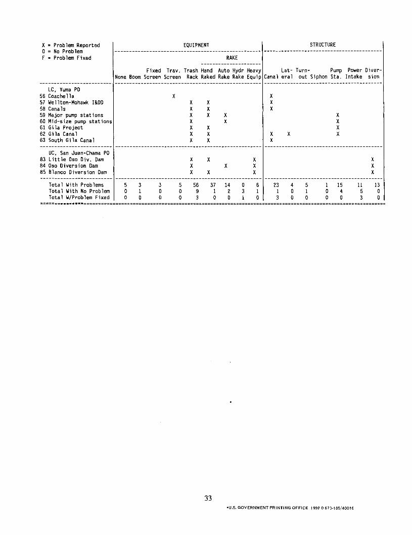
x Xx X Xx X Xx X X XX X XX X XX X X X XX X X
---------------------------------------------------------------------------------------------------------------------Total With Problems 5 3 3 5 56 37 14 0 6 23 4 5 1 15 11 13Total With No Problem 0 1 0 0 9 1 2 3 1 1 0 1 0 4 5 0Total W/Problem Fixed 0 0 0 0 3 0 0 1 0 3 0 0 0 0 3 0
x = Problem Reported0 = No ProblemF = Problem Fixed
EQUIPMENT STRUCTURE
-----------------------------------------RAKE
---------------------Fixed Trav. Trash Hand Auto Hydr Heavy Lat- Turn- Pump Power Diver-
None BoomScreen Screen Rack Raked Rake Rake Equip Canal eral out Siphon Sta. Intake sion-----------------------------------------
LC, Yuma PO56 Coachella57 Wellton-Mohawk I&DD58 Canals59 Major pump stations60 Mid-size pump stations61 Gila Project62 Gila Canal63 South Gila Canal
-----------------------------------------UC, San Juan-Chama PO
83 Little Oso Div. Dam84 Oso Diversion Dam85 Blanco Diversion Dam
XXX
X XXX
XXX
XX
========================================================================================================================
33-U.s. GOVERNMENT PRINTING OFFICE 1992-0-673-185/40016

Mission of the Bureau of Reclamation
The Bureau of Reclamation of the U.S. Department of the Interior is responsible for the development and conservation of the Nation's water resources in the Western United States.
The Bureau's original purpose "to provide for the reclamation of arid and semiarid lands in the West" today covers a wide range of interrelated functions. These include providing municipal and industrial water supplies; hydroelectric power generation; irrigation water for agriculture; water quality improvement; flood control; river navigation; river regulation and control; fish and wildlife enhancement; outdoor recreation; and research on water-related design, construction, materials, atmospheric management, and wind and solar power.
Bureau programs most frequently are the result of close cooperation with the U.S. Congress, other Federal agencies, States, local governments, academic institutions, water-user organizations, and other concerned groups.
A free pamphlet is available from the Bureau entitled "Publications for Sale." It describes some of the technical publications currently available, their cost, and how to order them. The pamphlet can be obtained upon request from the Bureau of Reclamation, Attn D-7923A, PO Box 25007, Denver Federal Center, Denver CO 80225-0007.