traymaster series deaerators - waterloo...
TRANSCRIPT

750-27301/09
Traymaster SeriesDeaerators
Operation, Maintenance and Parts

TO: Owners, Operators and/or Maintenance Personnel
This operating manual presents information that will help to properly operate and care for the equipment. Study its con-tents carefully. The unit will provide good service and continued operation if proper operating and maintenance instruc-tions are followed. No attempt should be made to operate the unit until the principles of operation and all of the components are thoroughly understood.
It is the responsibility of the owner to train and advise not only his or her personnel, but the contractors' personnel who are servicing, repairing, or operating the equipment, in all safety aspects.
Cleaver-Brooks equipment is designed and engineered to give long life and excellent service on the job. The electrical and mechanical devices supplied as part of the unit were chosen because of their known ability to perform; however, proper operating techniques and maintenance procedures must be followed at all times.
Any "automatic" features included in the design do not relieve the attendant of any responsibility. Such features merely free him of certain repetitive chores and give him more time to devote to the proper upkeep of equipment.
It is solely the operator’s responsibility to properly operate and maintain the equipment. No amount of written instruc-tions can replace intelligent thinking and reasoning and this manual is not intended to relieve the operating personnel of the responsibility for proper operation. On the other hand, a thorough understanding of this manual is required before attempting to operate, maintain, service, or repair this equipment.
Operating controls will normally function for long periods of time and we have found that some operators become lax in their daily or monthly testing, assuming that normal operation will continue indefinitely. Malfunctions of controls lead to uneconomical operation and damage and, in most cases, these conditions can be traced directly to carelessness and deficiencies in testing and maintenance.
The operation of this equipment by the owner and his operating personnel must comply with all requirements or regula-tions of his insurance company and/or other authority having jurisdiction. In the event of any conflict or inconsistency between such requirements and the warnings or instructions contained herein, please contact Cleaver-Brooks before pro-ceeding.

Cleaver-BrooksTRAYMASTER Series
DeaeratorsOperation, Maintenance and Parts
Manual Part No. 750-27301/09
Please direct purchase orders for replacement manuals to your local Cleaver-Brooks authorized representative
Printed in U.S.A.

Table of Contents
Section1Introduction
Introduction . . . . . . . . . . . . . . . . . . . . . . . . . . . . . . . . . . . . . . . . . . 1-2Component / Connection Locations . . . . . . . . . . . . . . . . . . . . . . . . . . 1-3Principles of Operation . . . . . . . . . . . . . . . . . . . . . . . . . . . . . . . . . . . 1-4
Section 2Installation
Installation - General . . . . . . . . . . . . . . . . . . . . . . . . . . . . . . . . . . . . 2-2System Layout/Piping Configurations . . . . . . . . . . . . . . . . . . . . . . . . . 2-2Steam Piping . . . . . . . . . . . . . . . . . . . . . . . . . . . . . . . . . . . . . . . . . 2-6Vent Valve . . . . . . . . . . . . . . . . . . . . . . . . . . . . . . . . . . . . . . . . . . . 2-6PRV and Safety Relief Valve . . . . . . . . . . . . . . . . . . . . . . . . . . . . . . . 2-7Pumps . . . . . . . . . . . . . . . . . . . . . . . . . . . . . . . . . . . . . . . . . . . . . . 2-9High Water Alarm . . . . . . . . . . . . . . . . . . . . . . . . . . . . . . . . . . . . . 2-15Low Water Alarm and LW Cutoff Series 64 McDonnell & Miller . . . . . . 2-16
Section 3Startup and Operation
Commissioning / Initial Startup . . . . . . . . . . . . . . . . . . . . . . . . . . . . . 3-2Operation and Adjustments . . . . . . . . . . . . . . . . . . . . . . . . . . . . . . . 3-2
Section 4Maintenance
General Maintenance . . . . . . . . . . . . . . . . . . . . . . . . . . . . . . . . . . . . 4-2Pumps . . . . . . . . . . . . . . . . . . . . . . . . . . . . . . . . . . . . . . . . . . . . . . 4-4Water Level Controls . . . . . . . . . . . . . . . . . . . . . . . . . . . . . . . . . . . . 4-9Overflow Trap . . . . . . . . . . . . . . . . . . . . . . . . . . . . . . . . . . . . . . . . 4-10
Section 5Troubleshooting
Deaerator Troubleshooting - General . . . . . . . . . . . . . . . . . . . . . . . . . 5-2Pumps . . . . . . . . . . . . . . . . . . . . . . . . . . . . . . . . . . . . . . . . . . . . . . 5-3High Water Alarm Series 63 McDonnell & Miller . . . . . . . . . . . . . . . . . 5-5Low Water Cutoff Series 64 McDonnell & Miller . . . . . . . . . . . . . . . . . 5-5Low Water Cutoff Series 93/193 McDonnell & Miller . . . . . . . . . . . . . . 5-6
Section 6Parts
Standard Traymaster Parts . . . . . . . . . . . . . . . . . . . . . . . . . . . 6-2Manway Cover Assemblies . . . . . . . . . . . . . . . . . . . . . . . . . . . 6-2Pressure Reducing Valves (Fisher 92 Series) . . . . . . . . . . . . . . 6-2Pressure Reducing Valves (Spence ED Series) . . . . . . . . . . . . . . 6-3Pressure Reducing Valves (Spence E2D Series) . . . . . . . . . . . . . 6-3Valve Sets for Gauge Glass . . . . . . . . . . . . . . . . . . . . . . . . . . . 6-4Overflow Drainer (Steam Trap) . . . . . . . . . . . . . . . . . . . . . . . . 6-4Siemens Actuator Series 599 . . . . . . . . . . . . . . . . . . . . . . . . . 6-5Siemens Actuator Series 599 . . . . . . . . . . . . . . . . . . . . . . . . . 6-6Wiring Diagram for use with Siemens Actuator Series 599 . . . . . 6-7Make-Up Controls (Fisher 171L) . . . . . . . . . . . . . . . . . . . . . . . 6-8Make-Up Controls (Fisher 670EK) . . . . . . . . . . . . . . . . . . . . . . 6-8Make-Up Controls (Fisher 608EK)) . . . . . . . . . . . . . . . . . . . . . 6-8

Make-Up Controls (Fisher 657ES) . . . . . . . . . . . . . . . . . . . . . . 6-8Spray Valve . . . . . . . . . . . . . . . . . . . . . . . . . . . . . . . . . . . . . 6-9Tray Assembly . . . . . . . . . . . . . . . . . . . . . . . . . . . . . . . . . . . 6-9Manway Assembly, 16" Davited, 50# D.P. . . . . . . . . . . . . . . 6-10Manway Assembly, 18" Davited, 50# D.P. . . . . . . . . . . . . . . 6-11Manway Assembly, 20" Davited, 50# D.P. . . . . . . . . . . . . . . 6-12Manway Assembly, 24" Davited, 50# D.P. . . . . . . . . . . . . . . 6-13Manway Assembly, 28" Davited, 50# D.P. . . . . . . . . . . . . . . 6-14Manway Assembly, 32" Davited, 50# D.P. . . . . . . . . . . . . . . 6-15Manway Assembly, 36" Davited, 50# D.P. . . . . . . . . . . . . . . 6-16

Notes
Milwaukee, Wisconsin
www.cleaver-brooks.com
Section 1Introduction
Introduction . . . . . . . . . . . . . . . . . . . . . . . . . . . . . . . . . . . . . . . . . . 1-2Component / Connection Locations . . . . . . . . . . . . . . . . . . . . . . . . . . 1-3Principles of Operation . . . . . . . . . . . . . . . . . . . . . . . . . . . . . . . . . . . 1-4

Section 1 — Introduction
1-2 Part No. 750-273
1.1.IntroductionThe Traymaster Deaerator (Figure 1-1) is designed to operate withsteam boilers in steam generation plants, or wherever oxygen-freewater is required.
Boiler feedwater usually contains two harmful dissolved gases -oxygen and carbon dioxide. The purpose of deaeration is to removethese gases before they are liberated in the boiler. This reducesoxidation corrosion in the boiler, steam lines, condensate lines, andheat transfer equipment.
The deaerator conditions feedwater so that it contains less than0.005 CC oxygen per liter. Residual oxygen is to be removed bychemical means. Carbon dioxide is, for all practical purposes,eliminated. In addition, the water is preheated as a result of thedeaeration process, thereby increasing the thermal efficiency of theboiler.
Deaerators are designed to operate on steam from the boiler,exhaust steam, or both. If exhaust or flash steam is currently goingto waste or vented to atmosphere, it may be used in the deaerator— reducing the fuel expense of the plant. There is a possible savingsof approximately 1% for each 10°F rise in boiler feedwatertemperature.
NOTE: Exhaust steam, if used, must be free of oils and othercontaminants, be of continuous supply, and at the requiredpressure. Care must be taken to avoid problems with the equipmentfrom which steam is extracted.
Figure 1-1 Traymaster Deaerator
Figure 1-2 Tray column - section view
Table 1-1 Standard Storage Tank CapacitiesTraymaster MODEL TMP030 TMP045 TMP070 TMP100 TMP125 TMP140 TMP175 TMP200 TMP225 TMP250 TMP300 TMP350 TMP400 TMP450 TMP500
TANK CAPACITY GALLONS
600 900 1400 200 2500 2800 3500 4000 4500 5000 6000 7000 8000 9000 10000
Section 1 — Introduction
Part No. 750-273 1-3
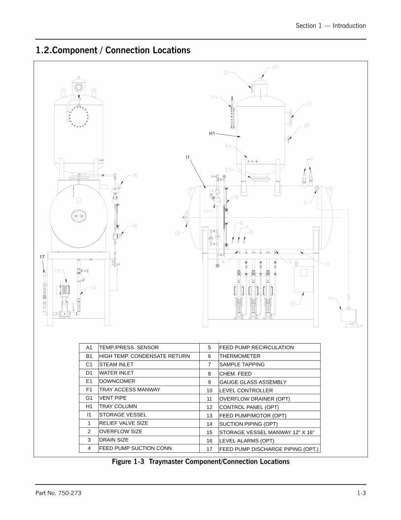
1.2.Component / Connection Locations
Figure 1-3 Traymaster Component/Connection Locations
17
H1
I1
A1 TEMP./PRESS. SENSOR 5 FEED PUMP RECIRCULATIONB1 HIGH TEMP. CONDENSATE RETURN 6 THERMOMETER C1 STEAM INLET 7 SAMPLE TAPPINGD1 WATER INLET 8 CHEM. FEED E1 DOWNCOMER 9 GAUGE GLASS ASSEMBLYF1 TRAY ACCESS MANWAY 10 LEVEL CONTROLLERG1 VENT PIPE 11 OVERFLOW DRAINER (OPT)H1 TRAY COLUMN 12 CONTROL PANEL (OPT)I1 STORAGE VESSEL 13 FEED PUMP/MOTOR (OPT)1 RELIEF VALVE SIZE 14 SUCTION PIPING (OPT)2 OVERFLOW SIZE 15 STORAGE VESSEL MANWAY 12" X 16"3 DRAIN SIZE 16 LEVEL ALARMS (OPT)4 FEED PUMP SUCTION CONN. 17 FEED PUMP DISCHARGE PIPING (OPT.)

Section 1 — Introduction
1-4 Part No. 750-273
1.3.Principles of OperationDeaeration in the Traymaster is a two-stage process. Water enteringthe tray section passes through a spring-loaded, self-cleaning sprayvalve and traverses the steam atmosphere of the upper portion ofthe tray box. The majority of deaeration occurs when the cold non-deaerated water comes into contact with saturated steam.
Now partially deaerated, the water begins to cascade downwardthrough the tray column as steam from the steam inlet flowsupward. The counter-flow of steam and water has the effect ofscrubbing dissolved gases from the feedwater. Deaerated waterpasses through the downcomer into the storage tank while gasesare eliminated through the vent. The vent pipe passes through theraw water containment vessel and transfers heat to the water beforeventing to atmosphere.
During the deaeration process the water temperature is raised towithin 2° or 3° of steam temperature and virtually all the gases arereleased to atmosphere.
A typical Cleaver-Brooks Traymaster Deaerator is shown in Figure 1-1, which illustrates a packaged type deaerator tank mounted on astand of appropriate height, and includes all operating controls andboiler feed pump(s), assembled and piped.
Cleaver-Brooks also supplies deaerator tanks for installation withpumps and stands provided by others. Standard components in thepackage include such items as relief valves for the tank, steampressure reducing valve, make-up water control valve, and anoverflow drainer. These components are provided with the deaeratortank, as their sizing is critical to proper operation.
The vessel is standardly a 50 psig ASME vessel containing anelliptical 12" x 16" manway and fitted with a 0-60 lb pressure gauge,a 50 – 300 °F thermometer, and water level gauge glass (orglasses).
The main deaerating column is mounted vertically on top of thehorizontal vessel and consists of a water inlet/vent condenser withspray valve, tray column, steam inlet, and downcomer. The waterinlet, tray box, and tray assemblies are all stainless steel. Trays areshipped pre-installed in the tray column.
Figure 1-4 Tray Column Steam and Water Flow
SteamInlet
Water Inlet
Deaerated Water
Vent

Milwaukee, Wisconsin
www.cleaver-brooks.com
Section 2Installation
Installation - General . . . . . . . . . . . . . . . . . . . . . . . . . . . . . . . . . . . . 2-2System Layout/Piping Configurations . . . . . . . . . . . . . . . . . . . . . . . . . 2-2Steam Piping . . . . . . . . . . . . . . . . . . . . . . . . . . . . . . . . . . . . . . . . . 2-6Vent Valve . . . . . . . . . . . . . . . . . . . . . . . . . . . . . . . . . . . . . . . . . . . 2-6PRV and Safety Relief Valve . . . . . . . . . . . . . . . . . . . . . . . . . . . . . . . 2-7Pumps . . . . . . . . . . . . . . . . . . . . . . . . . . . . . . . . . . . . . . . . . . . . . . 2-9High Water Alarm . . . . . . . . . . . . . . . . . . . . . . . . . . . . . . . . . . . . . 2-15Low Water Alarm and LW Cutoff Series 64 McDonnell & Miller . . . . . . 2-16

Section 2 — Installation
2-2 Part No. 750-273
2.1.Installation - GeneralSome installations may use specialized equipment not covered inthis manual. In such cases, refer to the manufacturer’s literature.Familiarize yourself with the instructions for the particular itemsfurnished.
Installation should conform to the manufacturer’s prints suppliedfor the system. Check all piping for proper connections. Check allvalves and controls to be sure they are installed with properdirection of flow.
All electrical work should be performed by a qualified electrician inaccordance with the latest edition of the National Electrical Code,local codes and regulations.
Note: Trays must be level for proper deaeration. Deaerator must beshimmed as necessary to ensure levelness. Out of level trays willresult in unequal distribution of water and incomplete deaeration.
2.2.System Layout/Piping Configurations Three typical system lay-outs are shown in Figures 2-1, 2-2, and 2-3 below. Note that in all cases the minimum supply water pressurerequirement is 10-12 lbs, and that the recommended steampressure within the deaerator storage tank is 5 psig.
If water exceeds 1 part per million of hardness, a water softener isrecommended.
All supply water to the deaerator, with the exception of uncontrolledcondensate return, must be limited to the maximum capacity of thedeaerator, whether the source is a condensate pump, a transferpump, or a city water supply. This is usually accomplished bymanual adjustment of a control valve in the transfer pump dischargeline. This adjustment is of extreme importance to proper operation.The make-up water must be modulated into the deaerator and mustnot exceed the deaeration capacity of the model.

Section 2 — Installation
Part No. 750-273 2-3
Plan AUnder normal operating conditions, the make-up water will beautomatically combined with low or medium temperature (up to 230deg F) condensate to maintain water in the storage tank at thecorrect level. Makeup water will only enter the system when thereis insufficient condensate return.
High pressure (high temperature) returns may be piped directly tothe deaerator’s tray column HP return connection. High pressuretrap returns are defined as being at a temperature greater than thenormal operating temperature of the deaerator or in excess of 230deg F.
Figure 2-1 System Layout - Plan A
M
RETURN SUMP
TOBOILER
OVERFLOWDRAINER
CONDENSATEPUMP
L.P.CONDENSATE
MAKE UPWATER
CONTROLVALVE
(GLOBE)
BOILERFEEDWATER
PUMP
RECOMMEND INSULATION
OF TANK AFTER
INSTALLATION
STEAM SOURCE(BOILER, FLASH,
EXHAUST)
H.P. RETURN(OVER 230° F)
RELIEFVALVE
LEVELCONTROL
SURGESTORAGE
STEAM PRESSUREREDUCING VALVE
MIN. WATER PRESSUREREQUIRED 10-12 PSIG
VENT
SYSTEM LAYOUTPLAN "A"
SOFTENER
MAKE UPVALVE
ELECTRIC=
PIPING=
LINE DESIGNATIONS
L.P.GRAVITYRETURNS
N.C.
N.C.
RECOMMENDEDOPERATING PRESSURE5 PSIG

Section 2 — Installation
2-4 Part No. 750-273
Plan BIn this layout the high pressure returns, low pressure returns, andcold water makeup are collected in the surge tank. The output of thetransfer pump is adjusted through a control valve to prevent floodingof the deaerator storage tank.
Figure 2-2 System Layout - Plan B
M
TOBOILER
OVERFLOWDRAINER
BOILERFEEDWATER
PUMP
RECOMMENDINSULATIONOF TANKAFTERINSTALLATION
STEAM
EXHAUST
STEAM
RELIEFVALVE
LEVELCONTROL
TANK
STEAM PRV
MIN. WATER PRESS. 10-12 PSIG
VENTSYSTEM LAYOUT
PLAN "B"
MAKE UPVALVE
ELECTRIC=
PIPING=
LINE DESIGNATIONS
STORAGE
RECOMMENDEDOPERATING PRESSURE
IS 5 PSIG
VALVEMAKE UP
PUMPTRANSFER
M
(GLOBE)
CONTROLVALVE
VENTLOW
RETURNS
OVERFLOW
LEVELCONTROL
WATERMAKE UP
HIGH PRESSURERETURN
PRESSURE

Section 2 — Installation
Part No. 750-273 2-5
Plan CIn this layout the high temperaturereturns and low pressure returnsare collected in the surge tank. The output of the transfer pump isadjusted through a control valve to prevent flooding of the deaeratorstorage tank.
Condensate return is used first as makeup.
Cold water makeup is used as a secondary makeup source.
Figure 2-3 System Layout - Plan C
M
TOBOILER
OVERFLOWDRAINER
BOILERFEEDWATER
PUMP
RECOMMENDINSULATIONOF TANKAFTERINSTALLATION
STEAM
EXHAUST
RELIEFVALVE
LEVELCONTROL
TANK
STEAM PRV
MIN. WATER PRESS. 10-12 PSIG
VENTSYSTEM LAYOUT
PLAN "C"
MAKE UPVALVE
ELECTRIC=
PIPING=
LINE DESIGNATIONS
STORAGE
RECOMMENDEDOPERATING PRESSURE
IS 5 PSIG
SECONDARY MAKE UP VALVE
PUMPTRANSFER
M
(GLOBE)
CONTROLVALVE
VENTLOW
RETURNS
OVERFLOW
CONTROL
WATERMAKE UP
HIGH PRESSURERETURN
PRESSURE
LEVELSECONDARYPRIMARYPRIMARY
HIGH PRESSURE RETURN(>230 deg F)
Section 2 — Installation
2-6 Part No. 750-273
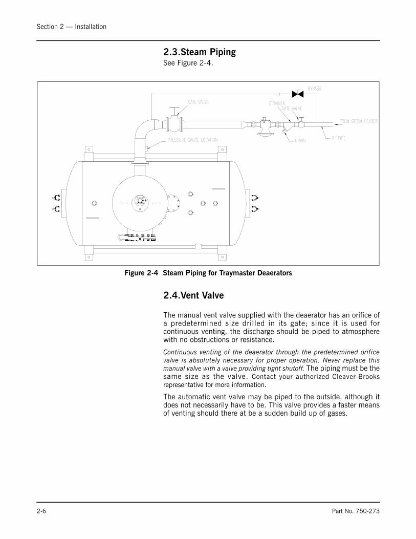
2.3.Steam PipingSee Figure 2-4.
2.4.Vent Valve
The manual vent valve supplied with the deaerator has an orifice ofa predetermined size drilled in its gate; since it is used forcontinuous venting, the discharge should be piped to atmospherewith no obstructions or resistance.
Continuous venting of the deaerator through the predetermined orificevalve is absolutely necessary for proper operation. Never replace thismanual valve with a valve providing tight shutoff. The piping must be thesame size as the valve. Contact your authorized Cleaver-Brooksrepresentative for more information.
The automatic vent valve may be piped to the outside, although itdoes not necessarily have to be. This valve provides a faster meansof venting should there at be a sudden build up of gases.
Figure 2-4 Steam Piping for Traymaster Deaerators
Section 2 — Installation
Part No. 750-273 2-7
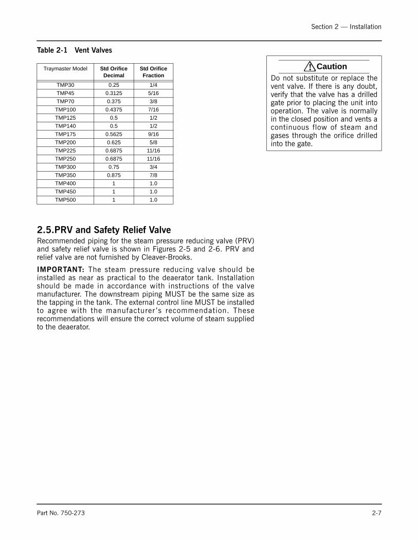
Table 2-1 Vent Valves
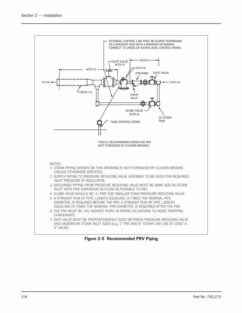
2.5.PRV and Safety Relief ValveRecommended piping for the steam pressure reducing valve (PRV)and safety relief valve is shown in Figures 2-5 and 2-6. PRV andrelief valve are not furnished by Cleaver-Brooks.
IMPORTANT: The steam pressure reducing valve should beinstalled as near as practical to the deaerator tank. Installationshould be made in accordance with instructions of the valvemanufacturer. The downstream piping MUST be the same size asthe tapping in the tank. The external control line MUST be installedto agree with the manufacturer ’s recommendation. Theserecommendations will ensure the correct volume of steam suppliedto the deaerator.
! CautionDo not substitute or replace thevent valve. If there is any doubt,verify that the valve has a drilledgate prior to placing the unit intooperation. The valve is normallyin the closed position and vents acontinuous flow of steam andgases through the orifice drilledinto the gate.
Traymaster Model Std Orifice Decimal
Std Orifice Fraction
TMP30 0.25 1/4TMP45 0.3125 5/16TMP70 0.375 3/8TMP100 0.4375 7/16TMP125 0.5 1/2TMP140 0.5 1/2TMP175 0.5625 9/16TMP200 0.625 5/8TMP225 0.6875 11/16TMP250 0.6875 11/16TMP300 0.75 3/4TMP350 0.875 7/8TMP400 1 1.0TMP450 1 1.0TMP500 1 1.0
Section 2 — Installation
2-8 Part No. 750-273
Figure 2-5 Recommended PRV Piping
NOTE #7
NOTE #5 NOTE #6
NOTE #5
NOTE #2
NOTE #4
DRAINVALVE

Section 2 — Installation
Part No. 750-273 2-9
2.6.PumpsIf a “packaged” type system was provided, the height of thedeaerator storage tank above the boiler feed pumps will have beenpredetermined to obtain proper NPSH; this height must be adheredto and should never be lowered.
If a deaerator storage tank only was supplied by Cleaver-Brooks andthe pumps by others, the tank must be mounted at a proper heightabove the pumps to avoid flashing and cavitation. The pumpmanufacturer’s recommendations must be followed.
Continuously operating centrifugal pumps must have a by-passorifice in the discharge line ahead of the check valve. This orifice isshipped loose with all centrifugal pumps.
Turbine pumps should be protected by a relief valve in the dischargeline when they operate against a feed water valve on the boiler.
Because of the various makes and models of pumps utilized with adeaerator, it is not practical to provide specific instructions in thismanual. The manufacturer’s literature provided with the pump
Figure 2-6 Recommended Safety Relief Valve Piping
Section 2 — Installation
2-10 Part No. 750-273
should be referred to. It provides instructions for proper mounting,piping, and alignment; these recommendations should be followed.
When pumps are provided by Cleaver-Brooks as a part of thedeaerator, care is taken to assure proper installation and alignment.It is extremely important, however, that alignment be recheckedprior to operation. A flexible coupling does not correct orcompensate for any misalignment between the pump and the motor.
There are general instructions applicable to all pumps. Most ofthese are listed in the various manufacturer’s literature, but they areworth repeating:
• Do not run the pump unless it is filled with liquid.
• Protect the pump from foreign particles, chips, scale, etc., using a suitable strainer installed in the suction line as near as possible to the pump.
• Suction and discharge piping must aline and not be forced into position when assembling to a pump. All piping must be supported to assure that no stresses or strains are transmitted to the pump.
• Verify that all discharge piping is open at start-up.
• In general, do not introduce boiler feed compound through a feed pump.
• Lubricate all bearings in accordance with manufacturer’s instructions. Remember that over greasing is harmful.
• When packed stuffing boxes are employed, adjustment will be required. Follow the manufacturer’s recommendation. Do not over-tighten. Adjust the packing only while the pump is running. Some leakage is required for lubrication and 40 to 60 drops per minute should not be considered excessive.
• Be sure that the pump shaft turns freely by hand. If it does not, some corrective action is required.
• Be sure wiring is connected for correct rotation as marked on the pump casing. In some cases, the flexible coupling insert on a pump provided by Cleaver-Brooks is removed prior to shipment. It is tied to the coupling along with a precautionary tag advising that motor rotation be established and verified. Incorrect rotation of some types of pumps, even momentarily, can cause serious pump damage.
Check rotation by momentarily energizing the pump starters.
Discharge pipingPipe, valves and fittings should be at least the same diameter as thedischarge pipe or sized in accordance with good piping practices toreduce excessive fluid velocities and pipe friction losses. Pipe,valves and fittings must have a pressure rating equal to or greaterthan the maximum system pressure. It is recommended that thedischarge piping be pressure checked to at least the maximumpressure the pump is capable of generating or as required by codesor local regulations. Operating pressure of the vessel must also betaken into consideration.

Section 2 — Installation
Part No. 750-273 2-11
Whenever possible, avoid high pressure loss fittings, such as elbowsor branch tees directly on either side of the pump. The piping shouldbe adequately supported to reduce thermal and mechanical stresseson the pump. Good installation practice recommends the system bethoroughly cleaned and flushed of all foreign materials andsediment prior to pump installation. Furthermore, the pump shouldnever be installed at the lowest point of the system due to thenatural accumulation of dirt and sediment. If there is excessivesediment or suspended particles present, it is advised a strainer orfilter be used. Grundfos recommends that pressure gauges beinstalled on inlet and discharge flanges or in pipes to check pumpand system performance.
Check valvesA check valve may be required on the discharge side of the pumpto prevent the pump’s inlet pressure from being exceeded. Forexample, if a pump with no check valve is stopped because there isno demand on the system (all valves are closed), the high systempressure on the discharge side of the pump will “find” its way backto the inlet of the pump. If the system pressure is greater than thepump’s maximum inlet pressure rating, the limits of the pump willbe exceeded and a check valve needs to be fitted on the dischargeside of the pump to prevent this condition.
BypassA bypass should be installed in the discharge pipe if there is anypossibility the pump may operate against a closed valve in thedischarge line. Flow through the pump is required to ensureadequate cooling and lubrication of the pump is maintained. Elbowsshould be a minimum of 12” from the orifice discharge to preventerosion.
MotorsPumps are supplied with heavy-duty 2-pole (3600 RPM nominal),ODP or TEFC, NEMA C f rame motors se lec ted to r ig idspecifications.
Motor protection1. Single-Phase Motors: With the exception of 10 HP motors which require externalprotection, single-phase CR pumps are equipped with multi-voltage, squirrel-cage induction motors with built-in thermalprotection.
2. Three-Phase Motors CR pumps with three-phase motors must be used with the propersize and type of motor-starter to ensure the motor is protectedagainst damage from low voltage, phase failure, current imbalanceand overloads. A properly sized starter with manual reset andambient- compensated extra quick trip in all three legs should beused. The overload should be sized and adjusted to the full-loadcurrent rating of the motor. Under no circumstances should theoverloads be set to a higher value than the full load current shownon the motor nameplate. This will void the warranty. Overloads for
Figure 2-7

Section 2 — Installation
2-12 Part No. 750-273
auto transformers and resistant starters should be sized inaccordance with the recommendations of the manufacturer. Threephase MLE motors require only fuses as a circuit breaker. They donot require a motor starter.NOTE: Standard allowable phaseimbalance difference is 5%.
Initial startup/primingTo prime the pump in a closed system or an open system where thewater source is above the pump, close the pump isolation valve(s)and open the priming plug on the pump head. See Figure 2-8,Figure 2-9, and Figure 2-10. Gradually open the isolation valve inthe suction line until a steady stream of airless water runs out thepriming port. Close the plug and securely tighten. Completely openthe isolation valves. For pumps with Cool-Top, see.
In open systems where the water level is below the pump inlet, thesuction pipe and pump must be filled and vented of air beforestarting the pump. Close the discharge isolation valve and removethe priming plug. Pour water through the priming hole until thesuction pipe and pump are completely filled with water. If thesuction pipe does not slope downward from the pump toward thewater level, the air must be purged while being filled. Replace thepriming plug and securely tighten.
1. Switch power off. 2. Check to make sure the pump has been filled and vented. 3. Remove the coupling guard and rotate the pump shaft by hand to
be certain it turns freely. 4. Verify that the electrical connections are in accordance with the
wiring diagram on the motor. 5. Switch the power on and observe the direction of rotation. When
viewed from the top, the pump should rotate counter-clockwise (clockwise for CRN-SF).
To reverse the direction of rotation, first switch OFF the supply power.
6. On three-phase motors, interchange any two power leads at the load side of the starter. On single-phase motors, see connection diagram on nameplate. Change wiring as required.8. Switch on the power and again check for proper motor rotation. Once rotation has been verified, switch off power again. Do not attempt to reinstall the coupling guards with the motor energized. Replace the coupling guard if the rotation is correct. After guards are in place the power can be reapplied.
! CautionThe safe operation of this pumprequires that it be grounded inaccordance with the nationale l e c t r i c a l c ode and l o ca lgoverning codes or regulations.
Figure 2-8 Drain Plugs
Pr iming Vent Plug
Suction
Drain Plug
Discharge

Section 2 — Installation
Part No. 750-273 2-13
INote: CR, CRI, CRN 1s to 5: For these pumps, it is advisable to openthe bypass valve (Figure 2-8) during start-up. The bypass valveconnects the suction and discharge sides of the pump, thus makingthe filling procedure easier. When the operation is stable, the bypassvalve must be closed.
REMINDER: Do not start the pump before priming or venting thepump. Never operate the pump dry.
Operating ParametersCR multi-stage centrifugal pumps installed in accordance with theseinstructions and sized for correct performance will operateefficiently and provide years of service. The pumps are water-lubricated and do not require any external lubrication or inspection.The motors may require periodic lubrication as noted in thefollowing Maintenance Section.
Under no circumstances should the pump be operated for anyprolonged periods of time without flow through the pump. This canresult in motor and pump damage due to overheating. A properlysized relief valve should be installed to allow sufficient water tocirculate through the pump to provide adequate cooling andlubrication of the pump bearings and seals.
Pump CyclingPump cycling should be checked to ensure the pump is not startingmore than: 20 times per hour on 1/3 to 5 HP models
15 times per hour on 7 1/2 to 15 HP models
10 times per hour on 20 to 60 HP models
Rapid cycling is a major cause of premature motor failure due toincreased heat build-up in the motor. If necessary, adjust controls toreduce the frequency of starts and stops.
Boiler-feed installationsIf the pump is being used as a boiler-feed pump, make sure thepump is capable of supplying sufficient water throughout its entireevaporation and pressure ranges. Where modulating control valvesare used, a bypass around the pump must be installed to ensurepump lubrication (see “Minimum Continuous Duty Flow Rates”).
Freeze ProtectionIf the pump is installed in an area where freezing could occur, thepump and system should be drained during freezing temperaturesto avoid damage. To drain the pump, close the isolation valves,remove the priming plug and drain plug at the base of the pump.Do not replace the plugs until the pump is to be used again. Alwaysreplace the drain plug with the original or exact replacement. Do notreplace with a standard plug. Internal recirculation will occur,reducing the output pressure and flow.
Figure 2-9 Drain Plugs
Figure 2-10 Vent Plug
! CautionMoto r s shou ld no t be r ununloaded or uncoupled from thepump at any time; damage to themotor bearings will occur.
Section 2 — Installation
2-14 Part No. 750-273
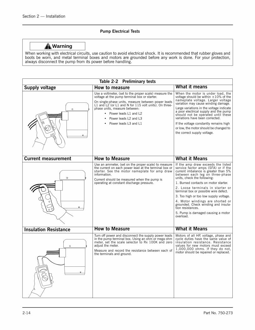
Pump Electrical Tests
! WarningWhen working with electrical circuits, use caution to avoid electrical shock. It is recommended that rubber gloves andboots be worn, and metal terminal boxes and motors are grounded before any work is done. For your protection,always disconnect the pump from its power before handling.
Table 2-2 Preliminary testsSupply voltage How to measure What it means
Use a voltmeter, (set to the proper scale) measure thevoltage at the pump terminal box or starter.
On single-phase units, measure between power leadsL1 and L2 (or L1 and N for 115 volt units). On three-phase units, measure between:
• Power leads L1 and L2
• Power leads L2 and L3
• Power leads L3 and L1
When the motor is under load, thevoltage should be within ±10% of thenameplate voltage. Larger voltagevariation may cause winding damage.Large variations in the voltage indicatea poor electrical supply and the pumpshould not be operated until thesevariations have been corrected.
If the voltage constantly remains high or low, the motor should be changed to the correct supply voltage.
Current measurement How to Measure What it MeansUse an ammeter, (set on the proper scale) to measurethe current on each power lead at the terminal box orstarter. See the motor nameplate for amp drawinformation.
Current should be measured when the pump is operating at constant discharge pressure.
If the amp draw exceeds the listedservice factor amps (SFA) or if thecurrent imbalance is greater than 5%between each leg on three-phaseunits, check the following:
1. Burned contacts on motor starter.
2. Loose terminals in star ter orterminal box or possible wire defect.
3. Too high or too low supply voltage.
4. Motor windings are shorted orgrounded. Check winding and insula-tion resistances.
5. Pump is damaged causing a motor overload.
Insulation Resistance How to Measure What it MeansTurn off power and disconnect the supply power leadsin the pump terminal box. Using an ohm or mega ohmmeter, set the scale selector to Rx 100K and zeroadjust the meter.
Measure and record the resistance between each ofthe terminals and ground.
Motors of all HP, voltage, phase andcycle duties have the same value ofinsulation resistance. Resistancevalues for new motors must exceed1,000,000 ohms. If they do not,motor should be repaired or replaced.

Section 2 — Installation
Part No. 750-273 2-15
2.7.High Water Alarm
Electrical Wiring
TOOLS NEEDED: One (1) flathead screwdriver.
Cover Removal and Installation Procedure
Using a flathead screwdriver, remove the one
(1) screw that secures the switch cover.
Place the cover on the switch housing and, using a flatheadscrewdriver, tighten the one
(1) screw to approximately 2 ft-lb. (2.6 Nm).
a. The No. 2 switch can be positioned with the conduit openingfacing toward or away from the float chamber. These are the onlypositions in which the switch will function properly.
See drawing at right.
b. On initial fill-up, push the 2M manual reset button after theproper water level is reached to energize the burner. If a low watercondition occurs and the water level has been restored, push thereset button to energize the burner.
c. Follow the wiring diagrams below to wire the No. 2 Switch.Terminals C and NC are the low water cut-off switch. Terminals Cand NO are alarm switch. If the electrical load exceeds the rating ofthe switch, use an auxiliary relay or motor starter.
! WarningTo prevent electrical shock, turn off the electrical power before making electrical connections.
Failure to follow this warning could cause electrical shock, an explosion and/or a fire, which could resultin property damage, personal injury or death.
Figure 2-11 Cover Removal
Figure 2-12
Conduit opening facing
toward float chamber
Conduit opening facing
away from float chamber
Manual reset button
on No. 2m Switch

Section 2 — Installation
2-16 Part No. 750-273
TestingControl can be tested on a deaerator by gently inserting ascrewdriver or similar tool in the test opening below the switch (seedrawing) and lifting linkage to cause float to drop, therebysimulating a low water condition.
2.8.Low Water Alarm and LW Cutoff Series 64 McDonnell
& Miller
CoverUsing a flathead screwdriver, remove the one (1) screw that securesthe switch cover (Fig. 2-15).
Figure 2-13
USED AS A MAIN LINE SWITCH
AND/OR LOW WATER ALARM
USED AS A PILOT SWITCH TO COIL
OF RELAY OR MOTOR STARTER
N. O.
N.C.
C.
N. O.
N.C.
C.
Neutral
120 V.A.C.
Supply Hot Low
Water
Alarm
Burner
Circuit
Line
Load
SCHEMATIC OF SWITCH OPERATION
Water Level Normal
Burner On
Alarm Off
Low
Water
Alarm
Terminals
Low Water
Cut-Off
Terminals
C.
N.O.
N.C.
Water Level Low
Burner Off
Alarm On
C.
N.O.
N.C.
N. O.
N.C.
C.
Figure 2-14 MM 63 Testing
CUT OFF
LEVEL
TEST
OPENING
Figure 2-15 Switch Cover
Cover

Section 2 — Installation
Part No. 750-273 2-17
Switch OperationThe No. 11 switch can be identified by a black terminal panel. Theswitch contains two (2) single pole single throw switches to controlthe water feeder and the low water cut-off. The low water cut-offswitch is between terminals marked ì1î and ì2î. A second switch islocated between terminals marked ì3î and ì4î.
This can be used to operate a low water alarm.
! WarningTo prevent electrical shock, turnoff the electrical power beforemaking electrical connections.Failure to follow this warningcould cause electrical shock, anexplosion and/or a fire, whichcould result in property damage,personal injury or death.
Figure 2-16 Switch Orientation
Figure 2-17
TOP LEFT BOTTOM RIGHT
TOP1 2
3 4
02
04
10
30
02
04
10
30
02
04
10
30
SCHEMATIC OF TWIN SWITCH
INTERNAL OPERATION
NORMAL WATER LEVEL
FEEDER OR ALARM
OPERATING LEVEL
LOW WATER CUT-OFF
OPERATING LEVEL

Section 2 — Installation
2-18 Part No. 750-273
Water Level Control Series 94 McDonnell & Miller
Wiring DiagramsNote: The following diagrams are provided for reference only. Ifavailable, manufacturers wiring diagrams should always be followedto connect the device being operated.
Figure 2-18 Replace Cover
CoverSwitch
Housing
Place the cover on the switch housing and, using
a flathead screwdriver, tighten the one (1) screw
to approximately 2 ft lb (2.6 N m).
! CautionTo prevent electrical shock, turn offthe electrical power before makingelectrical connections. Failure tofollow this warning could causeelectrical shock, an explosion and/ora fire, which could result inpropertydamage, personal injury or death.

Section 2 — Installation
Part No. 750-273 2-19
Figure 2-19
Figure 2-20
2 4
1 3
BLUE
BOILER FEED PUMP OFF BOILER FEED PUMP ON BOILER FEED PUMP ON
RED
3 1
4 2
2 4
1 3
BLUE RED
3 1
4 2
2 4
1 3
BLUE RED
3 1
4 2
Red switch terminals 1 and 2 are for burner circuit contacts, terminals 3 and 4 are for the low level alarm
circuit contacts.
Blue switch terminals 3 and 4 are for feeder/pump control contacts, terminals 1 and 2 are for high level
alarm circuit contacts.
BLUE
NO. 5
SWITCH
TO BURNERTO PUMP
LINE
1
2
3
4
4
3
RED
LINE
ALARM
TRANS.

Section 2 — Installation
2-20 Part No. 750-273
Figure 2-21 Low Water Cut-Off Only
Figure 2-22 Pump Control Only
Figure 2-23 Low Water Alarm Only
LOW WATER CUT-OFF CIRCUIT
BLUE
NO. 5
SWITCH
BURNER
STARTER
1
2
RED
LINE
PUMP CONTROL CIRCUIT
BLUE
NO. 5
SWITCH
PUMP
STARTER
4
3
RED
LINE
ALARM CIRCUIT
BLUE
NO. 5
SWITCH
ALARM
TRANS.
NEUTRAL
3
4
RED
LINE

Section 2 — Installation
Part No. 750-273 2-21
Figure 2-24 Series 93/193 or 94/194 with 7B or 7B-M
2 4
1 3
BLUE
BURNER ON–ALARM OFF
VALVE CLOSED
BURNER ON–ALARM OFF
VALVE OPEN
BURNER OFF–ALARM ON
VALVE OPEN
RED
3 1
4
2 4
1 3
BLUERED
3 1
4
2 4
1 3
BLUERED
3 1
4
NOTE: The 7B switch is a 135 ohm potentiometer slide
wire control for use with an electric valve operator with
the same rating.
Red terminals 3 and 4 are the burner circuit contacts, terminals 1 and 2 are the low level alarm circuit
contacts.
Blue terminal 3 is the common contact, terminals 1 and 4 are the output contacts.
Figure 2-25 Proportional Control, Low Water Cut-Off and Alarm
TO BURNER
LINE
13
4
4
3
2
1
COMMON
CLOSING CIRCUIT
OPENING CIRCUIT
NO. 7B
SWITCH
BLUERED
Section 2 — Installation
2-22 Part No. 750-273
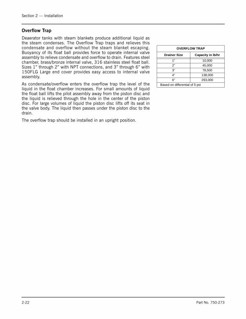
Overflow Trap
Deaerator tanks with steam blankets produce additional liquid asthe steam condenses. The Overflow Trap traps and relieves thiscondensate and overflow without the steam blanket escaping.Buoyancy of its float ball provides force to operate internal valveassembly to relieve condensate and overflow to drain. Features steelchamber, brass/bronze internal valve, 316 stainless steel float ball.Sizes 1” through 2” with NPT connections, and 3” through 6” with150FLG Large end cover provides easy access to internal valveassembly.
As condensate/overflow enters the overflow trap the level of theliquid in the float chamber increases. For small amounts of liquidthe float ball lifts the pilot assembly away from the piston disc andthe liquid is relieved through the hole in the center of the pistondisc. For large volumes of liquid the piston disc lifts off its seat inthe valve body. The liquid then passes under the piston disc to thedrain.
The overflow trap should be installed in an upright position.
OVERFLOW TRAP
Drainer Size Capacity in lb/hr
1” 10,0002” 45,0003” 78,5004” 138,0006” 293,000
Based on differential of 5 psi

Milwaukee, Wisconsin
www.cleaver-brooks.com
Section 3Startup and Operation
Commissioning / Initial Startup . . . . . . . . . . . . . . . . . . . . . . . . . . . . . 3-2Operation and Adjustments . . . . . . . . . . . . . . . . . . . . . . . . . . . . . . . 3-2

Section 3 — Startup and Operation
3-2 Part No. 750-273
3.1.Commissioning / Initial StartupOpen the gauge glass shut-off cocks and the vent cock on thedrainer. The manual vent valve may be opened to provide fasterventing. Open the valves in the supply line to the steam pressureregulator and close the by-pass valve.
If the boiler is empty and will be filled from this tank, close thepump discharge shut-off valve. Be sure that the pump is turned off.
Start water flow, but at a controlled rate so that capacity of thedeaerator is not exceeded.
NoticeAll supply water to the deaerator must be limited to the maximumcapacity of the deaerator whether the source be from acondensate pump, a transfer pump, or a city water supply. Thisis usually accomplished by manual adjustment of a control valvein the discharge line. This adjustment is of extreme importanceto proper operation.
When the correct water level is reached, open the pump valves andstart the feed water pump to fill the boiler. Observe the water levelduring this process to assure that the pump does not run dry.
Fire the boiler and bring it up to operating pressure in accordancewith good practice and the boiler manufacturer's recommendations.
When normal operating pressure is obtained, adjust the steampressure reducing valve to provide 5 psig within the tank.
Close the vent cock on the drainer when steam begins to flow fromit.
If the manual vent valve was opened, it should now be closed toprovide the desired rate of venting. The orifice in the valve gate willprovide a predetermined and sufficient vent rate.
Be sure that the orifice vent valve supplied with the unit is installed.
3.2.Operation and AdjustmentsFor deaeration to occur, it is necessary to raise the temperature ofthe incoming water to a point where oxygen and carbon dioxide arereleased from the water. This is accomplished by spraying the waterinto a steam filled chamber and through a spray of high velocitysteam.
Suitable deaeration will take place if the operating pressure withinthe tank is maintained at 5 psig and 227° F.
NOTE: 227° F is the saturation temperature of steam at 5 psig.Although operation is possible with steam pressures ranging from 2to 15 psig, 5 psig is the recommended operating pressure.
There are relatively few adjustments required. However, it isimportant that these adjustments be made under normal loadconditions.

Section 3 — Startup and Operation
Part No. 750-273 3-3
It is necessary to control the volume of water entering the deaeratorin relation to the inlet water temperature and to stay within the heatlimitation of the steam flow. Failure to maintain the desiredoperating pressure and temperature can generally be attributed toeither too much inlet water or too little steam.
The modulating make-up valve size is predicated on the total loadand the inlet water pressure. This determines the maximum flowcapacity (GPM) at a given supply pressure. When the valve is sizedon the basis of accurate data, it will be close to, or slightly above,the maximum requirement. Depending upon conditions, it may benecessary to throttle the flow of water to the make-up valve. Thisrequires a control valve (globe type) or possibly a pressure reducingvalve. This valve may be provided with the system, or it may beprovided by others.
When throttling is necessary, an initial adjustment made when thedeaerator is operating at capacity is normally sufficient. Manuallyadjust the control valve so that a fairly stable water level will bemaintained under the maximum load. The make-up valve willmodulate to maintain a relatively constant level under other loadconditions.
Always observe the water level in the gauge glass and make anynecessary re-adjustment to maintain the desired level.
If the flow of “cool” water is too great, it will quickly condense theincoming steam making it difficult to maintain the desired pressureand temperature.
If the flow is insufficient, due to over-throttling the control valve, orfrom lower than anticipated water pressure, it is possible for lowwater to occur. This can cause pump cavitation – possibly damagingthe pump – and eventual deaerator shut down.
When the water flow is established under normal load conditions,adjust the steam pressure regulator to maintain a 5 psig pressurewithin the tank. Adjustment should be performed in accordancewith the recommendation of the regulator manufacturer.
Once the unit has leveled out under normal operating conditionsand the liquid level control is operating automatically, operation isessentially automatic. No further adjustments should be requiredunless there is a change in operating conditions. Log book recordingof all pressures and temperatures on a daily basis will alertoperating personnel to deviations and the need for adjustments.
If adjustments to make-up or steam flows are necessary duringnormal operation, make the adjustments smoothly in smallincrements in order to maintain a good heat balance.
Normally there are no re-adjustments required when beginning froma cold start, for example after a week-end shut down.
For a normal shut down, such as a week-end, it is usually onlynecessary to secure the necessary supply, drain, or shut-off valvesand the pumps. Depending upon the installation, it may beadvisable to turn off the boiler feed pump during this shut down andto close the pump discharge valve. This will help prevent any

Section 3 — Startup and Operation
3-4 Part No. 750-273
vacuum caused by the cooling boiler water from pulling water fromthe deaerator, or from draining water from an elevated tank toequalize water levels between the boiler and the tank, or to possiblyflood the boilers.
Before resuming operation, verify that all valves are returned to theirnormal operating position.
Depending upon conditions, ambient temperature, length of shutdown, etc. the water temperature in the deaerator tank may havecooled considerably. Because of the advantage of feeding hotdeaerated water to the boiler as soon as possible, it may bedesirable to speed up heating of the water more quickly than normaloperation will accomplish. This can be done as soon as steam isavailable by manually operating the drain valve to dump water sothat make-up water and steam will enter. Care must be taken not tooverload the system or to starve the pump. When the desiredoperating temperature and pressure are obtained be sure to tightlyshut the drain valve.
During shut downs, especially seasonal or extended periods,chemical treatment of the water in the deaerator is required.Yourfeedwater consultant’s recommendations regarding the use of anoxygen scavenger should be followed.

Milwaukee, Wisconsin
www.cleaver-brooks.com
Section 4Maintenance
General Maintenance . . . . . . . . . . . . . . . . . . . . . . . . . . . . . . . . . . . . 4-2Pumps . . . . . . . . . . . . . . . . . . . . . . . . . . . . . . . . . . . . . . . . . . . . . . 4-4Water Level Controls . . . . . . . . . . . . . . . . . . . . . . . . . . . . . . . . . . . . 4-9Overflow Trap . . . . . . . . . . . . . . . . . . . . . . . . . . . . . . . . . . . . . . . . 4-10

Section 4 — Maintenance
4-2 Part No. 750-273
4.1.General MaintenanceCleaver-Brooks equipment is designed, engineered, and built toprovide long life and excellent service on the job. Good operatingpractices and conscientious maintenance and care will obtainefficiency and economy from their operation and contribute to longyears of performance.
A well planned maintenance program avoids unnecessary downtime or costly repairs, promotes safety, and aids boiler code andlocal inspectors. An inspection schedule with a listing of proceduresshould be established. It is recommended that a boiler room log, orrecord, be maintained. Recording of daily, weekly, monthly andyearly maintenance activities provides a valuable guide and aids inobtaining economies and length of service from Cleaver-Brooksequipment.
Even though the deaerator has electrical and mechanical devicesthat make it operate automatically, these devices require systematicand periodic maintenance. Any “automatic” features do not relievethe operator from responsibility, but rather free him of somerepetitive chores, providing time to devote to maintenance.
Only trained and authorized personnel should be permitted tooperate, adjust or repair the boiler and its related equipment.
Good housekeeping helps maintain a professional appearing boilerroom. The boiler room should be kept free of all material andequipment not necessary to the operation of the boiler or heatingsystem.
Alertness in recognizing unusual noises, improper gauge reading,leaks, etc., can make the operator aware of a developingmalfunction, permitting prompt corrective action that may preventextensive repairs or unexpected down time. Any steam, water or fuelleaks should be repaired as soon as they are noticed. These arewasteful as well as hazardous. Include in the program preventivemaintenance measures such as regularly checking the tightness ofconnections, locknuts, setscrews, packing glands, etc.
Insurance regulations or local laws may require a periodicinspection of the pressure vessel by an authorized inspector.
Inspections of this type are usually, though not necessarily,scheduled for periods of normal boiler down time such as an offseason. This major inspection can often be used to accomplishmaintenance, replacements, or repairs that cannot easily be doneat other times. This also serves as a good basis for establishing aschedule for annual, monthly, or other periodic maintenanceprograms.
While this inspection pertains primarily to the waterside and firesidesurfaces of the boiler, it provides an excellent opportunity fordetailed inspection and checking of all components of the systemincluding piping, valves, pumps, gaskets, sof tener, etc.Comprehensive cleaning, spot painting or re-painting, and thereplacement of expendable items, should be planned for and takencare of during this time. Any major repairs or replacements that may

Section 4 — Maintenance
Part No. 750-273 4-3
be required should also, if possible, be coordinated with this periodof boiler shutdown.
Replacement spare parts, if not on hand, should be orderedsufficiently prior to shutdown.
Trays are subject to scale buildup if the water being used is high inhardness or alkalinity. Routine inspection and cleaning arerecommended. A hinged door in the tray column provides access tothe tray box. The tray box itself has a door fastened with sash pinsfor easy access.
In the event there is an accumulation of sediment, sand, gravel, etc.in the bottom of the tank, it should be removed, analyzed, and aneffort made to eliminate the source.
Should scale be present, the method of cleaning, either mechanicalor chemical, will be governed by the composition of the scale andits location. If cleaning is required, it is suggested that the cleaningproblem be referred to a company that is versed in this type ofcleaning. They will be able to determine the composition of thescale and will select the proper chemicals to be employed in thecleaning process.
Periodic checks for water softness should be maintained. Ifhardness exceeds three grains per gallon, a water softener shouldbe used to prevent build up of mineral deposits on the internal partsof the deaerator.
The water spray nozzle is of the self-cleaning type. Clogging orwearing seldom occurs, however, it is a possibility that should bechecked in the event problems are encountered. This is a spring-loaded valve and it is factory pre-set. Should disassembly oradjustment become necessary, tighten the spring with the spraydisc closed, compressing it 3/16". Be sure that the jam nut lockstightly against the adjusting nut.
Float-operated controls should be blown down or drained routinelyto assure against build up of sediment that may interfere with theirfunction. It is suggested that the heads be removed for visualinspection during the annual boiler inspection. At the same time,remove the pipe plugs from the tees or crosses to verify that thecross connecting piping is clean and free of obstructions. Controlsmust be mounted in a plumb position for proper performance.Determine that piping is vertically aligned after shipment andinstallation, and throughout life of equipment.
The water gauge glass should be kept clean. Check while cool foretching thinning or damage. If any deterioration is found, replaceglass immediately to avoid the possibility of breakage in service.The glass should be replaced periodically as par t of themaintenance program. Always use new gaskets when replacing aglass. Do not over tighten water gauge glass fittings. Check try-cocks and gauge cocks for freedom of operation and clean asrequired. Proper alignment of gauge glass cocks is essential toprevent mechanical strain on the glass.
Check and clean all drain valves.
Section 4 — Maintenance
4-4 Part No. 750-273
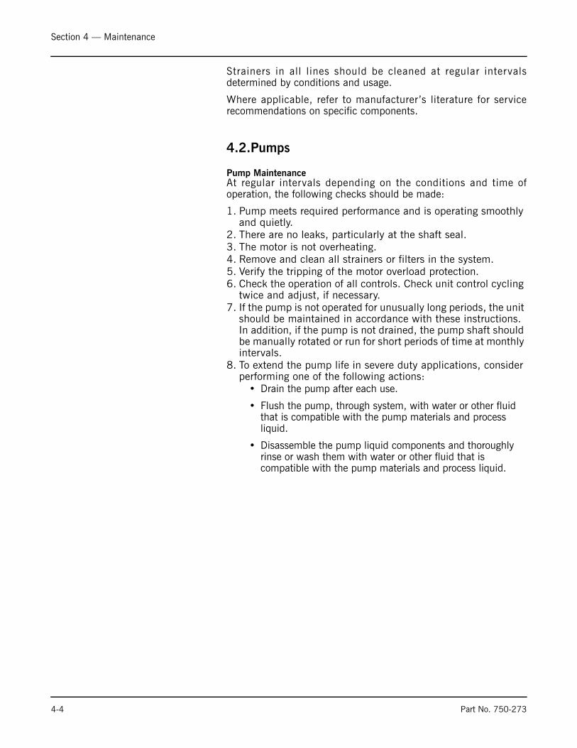
Strainers in all lines should be cleaned at regular intervalsdetermined by conditions and usage.
Where applicable, refer to manufacturer ’s literature for servicerecommendations on specific components.
4.2.Pumps
Pump MaintenanceAt regular intervals depending on the conditions and time ofoperation, the following checks should be made:
1. Pump meets required performance and is operating smoothly and quietly.
2. There are no leaks, particularly at the shaft seal. 3. The motor is not overheating. 4. Remove and clean all strainers or filters in the system. 5. Verify the tripping of the motor overload protection. 6. Check the operation of all controls. Check unit control cycling
twice and adjust, if necessary. 7. If the pump is not operated for unusually long periods, the unit
should be maintained in accordance with these instructions. In addition, if the pump is not drained, the pump shaft should be manually rotated or run for short periods of time at monthly intervals.
8. To extend the pump life in severe duty applications, consider performing one of the following actions:
• Drain the pump after each use.
• Flush the pump, through system, with water or other fluid that is compatible with the pump materials and process liquid.
• Disassemble the pump liquid components and thoroughly rinse or wash them with water or other fluid that is compatible with the pump materials and process liquid.

Section 4 — Maintenance
Part No. 750-273 4-5
If the pump fails to operate or there is a loss of performance, referto the Troubleshooting Section.
Motor Replacement
If the motor is damaged due to bearing failure, burning or electricalfailure, the following instructions detail how to remove the motor forreplacement. It must be emphasized that motors used on CR pumpsare specifically selected to our rigid specifications.
Replacement motors must be of the same frame size, should beequipped with the same or better bearings and have the sameservice factor. Failure to follow these recommendations may resultin premature motor failure.
Disassembly 1. Turn off and lock out power supply. The power supply wiring
can not be safely disconnected from the motor wires. 2. . Remove the coupling guards.
CR 1s, 1, 3, 5, 10, 15, and 20: do not loosen the three shaft sealsecuring allen screws.
3. Using the proper metric Allen wrench, loosen the four cap screws in the coupling. Completely remove coupling halves. On CR1s-CR20, the shaft pin can be left in the pump shaft. CR(N)32, 45, 64 and 90 do not have a shaft pin.
4. With the correct size wrench, loosen and remove the four bolts which hold the motor to the pump end.
5. Lift the motor straight up until the shaft has cleared the motor stool.
Assembly 1. Remove key from motor shaft, if present, and discard. 2. Thoroughly clean the surfaces of the motor and pump end
mounting flange. The motor and shaft must be clean of all oil/grease and other contaminants where the coupling attaches. Set the motor on the pump end.
3. Place the terminal box in the desired position by rotating the motor.
4. Insert the mounting bolts, then diagonally and evenly tighten. For 3/8” bolts (1/2 to 2 HP), torque to 17 ft.-lbs., for 1/2” bolts (3 to 40 HP) torque to 30 ft.-lbs., and for 5/8” bolts (50 - 60 HP) torque to 59 ft.-lbs.
CR 1s, 1, 3, and 5:
Insert shaft pin into shaft hole. Reinstall the coupling halves ontoshaft and shaft pin. Reinstall the coupling screws and leave loose.Check that the gaps on either side of the coupling are even, and thatthe motor shaft keyway is centered in the coupling half, as shownin Figure 4-2. Tighten the screws to the correct torque.
CR 10, 15 and 20:
Insert shaft pin into shaft hole. Insert plastic shaft seal spacerbeneath shaft seal collar. Reinstall the coupling halves onto shaft
Figure 4-1
• Note the clearancebelow the coupling
• Raise the couplinghigher, as far as itwill go.
• Lower it halfway backdown (1/2 the distanceyou just raised it).
• Tighten screws(see torque specifica-tions below)
Torque Specifications
CR(I)(N) 1s, 1, 3, 5, 10, 15, and 20CRT 2, 4, 8, and 16
Coupling Bolt Size
Min. Torque Specifications
M6 10 ft-lbs.M8 23 ft-lbs.
M10 46 ft-lbs.

Section 4 — Maintenance
4-6 Part No. 750-273
and shaft pin. Reinstall the coupling screws and leave loose. Checkthat the gaps on either side of the coupling are even and that themotor shaft key way is centered in the coupling half, as shown inFigure 4-2. Tighten the screws to the correct torque. Remove plasticshaft seal spacer and hang it on inside of coupling guard.
CRT 2, 4, 8 and 16:
Reinstall coupling halves. Make sure the shaft pin is located in thepump shaft. Put the cap screws loosely back into the couplinghalves. Using a large screwdriver, raise the pump shaft by placingthe tip of the screwdriver under the coupling and carefully elevatingthe coupling to its highest point (Figure 4-1). Note: the shaft canonly be raised approximately 0.20 inches (5mm). Now lower theshaft half way back down the distance you just raised it and tightenthe coupling screws (finger tight) while keeping the couplingseparation equal on both sides. When the screws are tight enoughto keep the couplings in place, then torque the screws evenly in acriss-cross pattern.
CR(N) 32, 45, 64 & CR90:
Place the plastic adjustment fork under the cartridge seal collar (seeFigure 4-3).
Fit the coupling on the shaft so that the top of the pump shaft isflush with the bottom of the clearance chamber in the coupling (seeFigure 4-3).
Lubricate the coupling screws with an anti-seize and lubricatingcompound. Tighten the coupling screws (finger tight) while keepingthe coupling separation equal on both sides and the motor shaftkeyway centered in the coupling half as shown in Figure 4-1.
When the screws are tight enough to keep the couplings in place,then torque the screws evenly in a crisscross pattern.
Torque coupling screws to 62 ft.-lbs. Remove the adjustment forkfrom under the cartridge seal collar and replace it to the storagelocation (see Figure 4-4).
5. Check to see that the gaps between the coupling halves are equal. Loosen and readjust, if necessary.
Figure 4-2
Ke yway Ke yway
Gap between coupling
CORRECT
To pVie w
CORRECT
NO T CORRECT
All CR(I)(N)(X)(T)

Section 4 — Maintenance
Part No. 750-273 4-7
6. Be certain the pump shaft can be rotated by hand. If the shaft cannot be rotated or it binds, disassemble and check for misalignment.
7. Prime the pump. 8. Follow the wiring diagram on the motor label for the correct
motor wiring combination which matches your supply voltage. Once this has been confirmed, reconnect the power supply wiring to the motor.
9. Check the direction of rotation, by bump-starting the motor. Rotation must be left to right (counter-clockwise) when looking directly at the coupling.
10.Shut off the power, then re-install the coupling guards. After the coupling guards have been installed the power can be turned back on.
Motor InspectionInspect the motor at regular intervals, approximately every 500hours of operation or every three months, whichever occurs first.Keep the motor clean and the ventilation openings clear. Thefollowing steps should be performed at each inspection:
1. Check that the motor is clean. Check that the interior and exteriorof the motor is free of dirt, oil, grease, water, etc. Oily vapor, paper,pulp, textile lint, etc. can accumulate and block motor ventilation.If the motor is not properly ventilated, overheating can occur andcause early motor failure.
2. Use an Ohmmeter periodically to ensure that the integrity of thewinding insulation has been maintained. Record the Ohmmeterreadings. Immediately investigate any significant drop in insulationresistance.
3. Check all electrical connectors to be sure that they are tight.
Motor LubricationElectric motors are pre-lubricated at the factory and do not requireadditional lubrication at start-up. Motors without external greasefittings have sealed bearings that cannot be re-lubricated. Motors
Figure 4-3
CR(N) 32, 45, 64, 90
Figure 4-4
! WarningDo no t t ouch e l ec t r i c a lconnections before you firstensure that power has beendisconnected. Electrical shockcan cause serious or fatal injury.Only qualified personnel shouldattempt installation, operation,and ma in t enance o f t h i sequipment.

Section 4 — Maintenance
4-8 Part No. 750-273
with grease fittings should only be lubricated with approved typesof grease. Do not over-grease the bearings. Over greasing will causeincreased bearing heat and can result in bearing/motor failure. Donot mix petroleum grease and silicon grease in motor bearings.
Bearing grease will lose its lubricating ability over time, notsuddenly. The lubricating ability of a grease (over time) dependsprimarily on the type of grease, the size of the bearings, the speedat which the bearings operate and the severity of the operatingconditions. Good results can be obtained if the followingrecommendations are used in your maintenance program. It shouldalso be noted that pumps with more stages, pumps running to theleft of the performance curve, certain pump ranges may have higherthrust loads. Pumps with high thrust loads should be greasedaccording to the next service interval level.
If pump is fitted with a bearing flange that requires grease, see thestickers on either the bearing flange or coupling guards for propergrease type and greasing schedule.
Motor Lubrication Schedule (for Motors with Grease Nipples)New motors that have been stored for a year or more should beregreased.
Table 4-1 Motor Lubrication Schedule
Procedure:
1. Clean all grease fittings. If the motor does not have grease fittings, the bearing is sealed and cannot be greased externally.
2. If the motor is equipped with a grease outlet plug, remove it. This will allow the old grease to be displaced by the new grease.
3. If the motor is stopped, add the recommended amount of grease. If the motor is to be greased while running, a slightly greater quantity of grease will have to be added.
Note: If new grease does not appear at the shaft hole or grease outletplug, the outlet passage may be blocked. At the next service intervalthe bearings must be repacked. Add grease SLOWLY takingapproximately one minute until new grease appears at the shaft holein the end plate or grease outlet plug. Never add more than 1-1/2times the amount of grease shown in the lubrication schedule.
4. For motors equipped with a grease outlet plug, let the motor run for 20 minutes before replacing the plug.
NEMA/(IEC) Frame Size StandardSer v iceInterval
SevereSer v i ceInterval
Ex t remeSer v iceInterval
Weight of Grease to AddOz./(Grams)
Volume of Grease toAdd In3/(Teaspoons)
Up through 210 (132) 5500 hrs. 2750 hrs. 550 hrs. 0.30 (8.4) 0.6 (2)Over 210 through 280 (180) 3600 hrs. 1800 hrs. 360 hrs. 0.61 (17.4)* 1.2 (3.9)*Over 280 up through 360 (225) 2200 hrs. 1100 hrs. 220 hrs. 0.81 (23.1)* 1.5 (5.2)*Over 360 (225) 2200 hrs. 1100 hrs. 220 hrs. 2.12 (60.0)* 4.1 (13.4)*
! CautionTo avo id damage to moto rbearings, grease must be keptfree of dirt. For an extremely dirtyenvironment, contact Grundfos,the motor manufacturer or anauthorized service center foradditional information. Mixingd i s s im i l a r g r ea se i s no trecommended.

Section 4 — Maintenance
Part No. 750-273 4-9
4.3.Water Level ControlsSeries 63 McDonnell & Miller
Maintenance Schedule:
• Blow down control as follows when the deaerator is in operation:
Steam: Daily if operating pressure is above 15 psi.Weekly if operating pressure is below 15 psi.
Hot Water: Quarterly
Note: More frequent blowdown may be necessary due to dirty water and/orlocal codes.
• Disassemble and inspect annually. Replace the low water cut-off if it is worn, corroded, or if components no longer operate properly.
• Inspect the float chamber and equalizing piping annually. Remove all sediment and debris.
• Replace head mechanism every 5 years. More frequent replacement may be required when severe conditions exist such as rapid switch cycling, surging water levels, and use of water treatment chemicals.
• We recommend head mechanism replacement when the switch(es) no longer operate properly. If you choose to replace the switch(es), order the proper McDonnell & Miller replacement switch or switch assembly and follow the Repair Procedure provided.
Blowdown procedure:1. Blow down the low water cut-off when the water level is at itsnormal level and the burner is on. Slowly open the blowdown valveuntil it is fully open and observe the water level fall in the gaugeglass. Close the valve after verifying that the pump contacts haveclosed and the burner shuts off. If this does not happen,immediately shut off the deaerator and correct the problem.
Series 64 McDonnell & Miller
Maintenance Schedule:
• Blow down weekly during heating season.• Open up float chamber and clean annually.
! CautionTo prevent serious personal injury from steam pipe blowdown,connect a drain pipe to the control opening to avoid exposure tosteam discharge. Failure to follow this caution could causepersonal injury.

Section 4 — Maintenance
4-10 Part No. 750-273
More frequent cleaning may be necessary if there are high make-upwater requirements or poor local water quality.
Replace control every 10 years.
Series 93/193 McDonnell & Miller
Maintenance Schedule:
• Blow down daily when the deaerator is in operation. Control should be blown down daily to flush accumulation of sediment from float chamber and verify operation of switches.
• Remove head assembly and inspect waterside components annually. Replace head assembly if any of the internal components are worn, corroded or damaged or if control no longer operates properly.
• Inspect the float chamber and equalizing piping annually. Remove all sediment and debris.
• Replace head mechanism every 5 years. More frequent replacement may be required when severe conditions exist such as rapid switch cycling, surging water levels, and use of water treatment chemicals.
• Replace unit every 15 years. More frequent replacement may be required when severe conditions exist.
Blowdown Procedure:Blow down the control when the water level is at its normal positionand the burner is on. Slowly open the blowdown valve until it is fullyopen and observe the water level fall in the gauge glass. Close thevalve after verifying that the pump contacts have closed and theburner shuts off. If the pump does not turn on and burner turn offwhen water level is lower, immediately shut off power to the pumpand deaerator and correct the problem.
4.4.Overflow Trap The inlet and outlet of the overflow trap must be kept unblocked.The internal valve assembly must be kept free of debris, deposits,and dirt. The internal valve assembly should move freely.
! CautionTo prevent ser ious personali n j u r y f r om s t eam p ipeblowdown, connect a drain pipeto the control opening to avoidexposure to steam discharge.Failure to follow this cautioncould cause personal injury.

Milwaukee, Wisconsin
www.cleaver-brooks.com
Section 5Troubleshooting
Deaerator Troubleshooting - General . . . . . . . . . . . . . . . . . . . . . . . . . 5-2Pumps . . . . . . . . . . . . . . . . . . . . . . . . . . . . . . . . . . . . . . . . . . . . . . 5-3High Water Alarm Series 63 McDonnell & Miller . . . . . . . . . . . . . . . . . 5-5Low Water Cutoff Series 64 McDonnell & Miller . . . . . . . . . . . . . . . . . 5-5Low Water Cutoff Series 93/193 McDonnell & Miller . . . . . . . . . . . . . . 5-6

Section 5 — Troubleshooting
5-2 Part No. 750-273
5.1.Deaerator Troubleshooting - General
Symptom Possible causeHigh O2 • Trays not installed properly or not level
• Improper venting• Steam pressure reducing valve sized improperly
Excessive pressure fluctuation • Steam pressure reducing valve sized improperly• Excessive inlet temperature variation• Deaerator flooding• Inlet steam pressure too high or too low
Low outlet temperature • Incorrect thermometer reading• Deaerator flooding• Insufficient steam flow• Spray valves malfunctioning• Improper venting• Steam pressure reducing valve piped improperly
Water Hammer • Inlet flows mixing just prior to deaerator inlet• High inlet velocities• Improper piping designs
High CO2 • High CO2 at inlet• High pH• Improper venting
Tray upsets • Tray hold down not secure• Flashing
Water escaping from vent • Improper vent piping• Water carryover• Cracked vent welds
Section 5 — Troubleshooting
Part No. 750-273 5-3
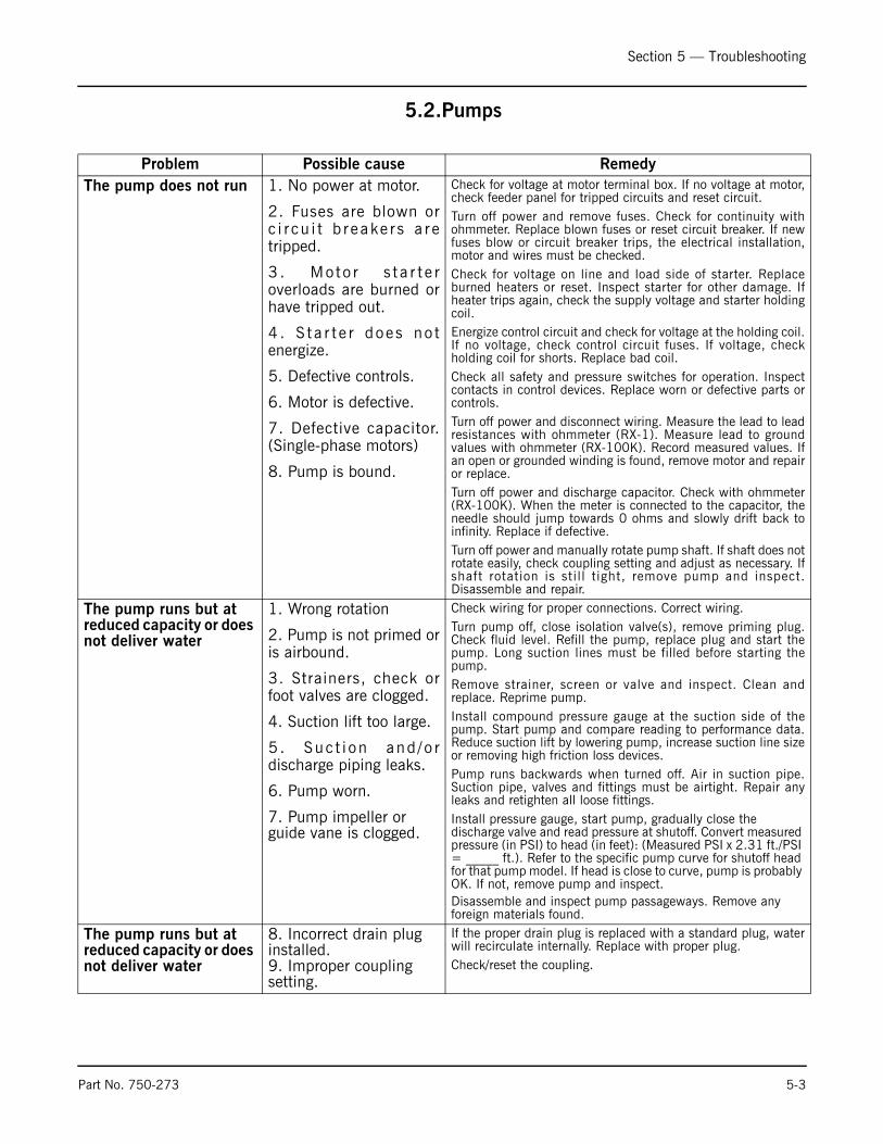
5.2.Pumps
Problem Possible cause RemedyThe pump does not run 1. No power at motor.
2. Fuses are blown orc i r cu i t b r eake r s a r etripped.
3 . Mo to r s t a r t e roverloads are burned orhave tripped out.
4 . S t a r t e r does no tenergize.
5. Defective controls.
6. Motor is defective.
7. Defective capacitor.(Single-phase motors)
8. Pump is bound.
Check for voltage at motor terminal box. If no voltage at motor,check feeder panel for tripped circuits and reset circuit.Turn off power and remove fuses. Check for continuity withohmmeter. Replace blown fuses or reset circuit breaker. If newfuses blow or circuit breaker trips, the electrical installation,motor and wires must be checked.Check for voltage on line and load side of starter. Replaceburned heaters or reset. Inspect starter for other damage. Ifheater trips again, check the supply voltage and starter holdingcoil.Energize control circuit and check for voltage at the holding coil.If no voltage, check control circuit fuses. If voltage, checkholding coil for shorts. Replace bad coil.Check all safety and pressure switches for operation. Inspectcontacts in control devices. Replace worn or defective parts orcontrols.Turn off power and disconnect wiring. Measure the lead to leadresistances with ohmmeter (RX-1). Measure lead to groundvalues with ohmmeter (RX-100K). Record measured values. Ifan open or grounded winding is found, remove motor and repairor replace.Turn off power and discharge capacitor. Check with ohmmeter(RX-100K). When the meter is connected to the capacitor, theneedle should jump towards 0 ohms and slowly drift back toinfinity. Replace if defective.Turn off power and manually rotate pump shaft. If shaft does notrotate easily, check coupling setting and adjust as necessary. Ifshaft rotation is still tight, remove pump and inspect.Disassemble and repair.
The pump runs but at reduced capacity or does not deliver water
1. Wrong rotation
2. Pump is not primed oris airbound.
3. Strainers, check orfoot valves are clogged.
4. Suction lift too large.
5 . Suc t i on and / o rdischarge piping leaks.
6. Pump worn.
7. Pump impeller or guide vane is clogged.
Check wiring for proper connections. Correct wiring.Turn pump off, close isolation valve(s), remove priming plug.Check fluid level. Refill the pump, replace plug and start thepump. Long suction lines must be filled before starting thepump.Remove strainer, screen or valve and inspect. Clean andreplace. Reprime pump.Install compound pressure gauge at the suction side of thepump. Start pump and compare reading to performance data.Reduce suction lift by lowering pump, increase suction line sizeor removing high friction loss devices.Pump runs backwards when turned off. Air in suction pipe.Suction pipe, valves and fittings must be airtight. Repair anyleaks and retighten all loose fittings.Install pressure gauge, start pump, gradually close the discharge valve and read pressure at shutoff. Convert measured pressure (in PSI) to head (in feet): (Measured PSI x 2.31 ft./PSI = _____ ft.). Refer to the specific pump curve for shutoff head for that pump model. If head is close to curve, pump is probably OK. If not, remove pump and inspect.Disassemble and inspect pump passageways. Remove any foreign materials found.
The pump runs but at reduced capacity or does not deliver water
8. Incorrect drain plug installed.9. Improper coupling setting.
If the proper drain plug is replaced with a standard plug, waterwill recirculate internally. Replace with proper plug.Check/reset the coupling.
Section 5 — Troubleshooting
5-4 Part No. 750-273
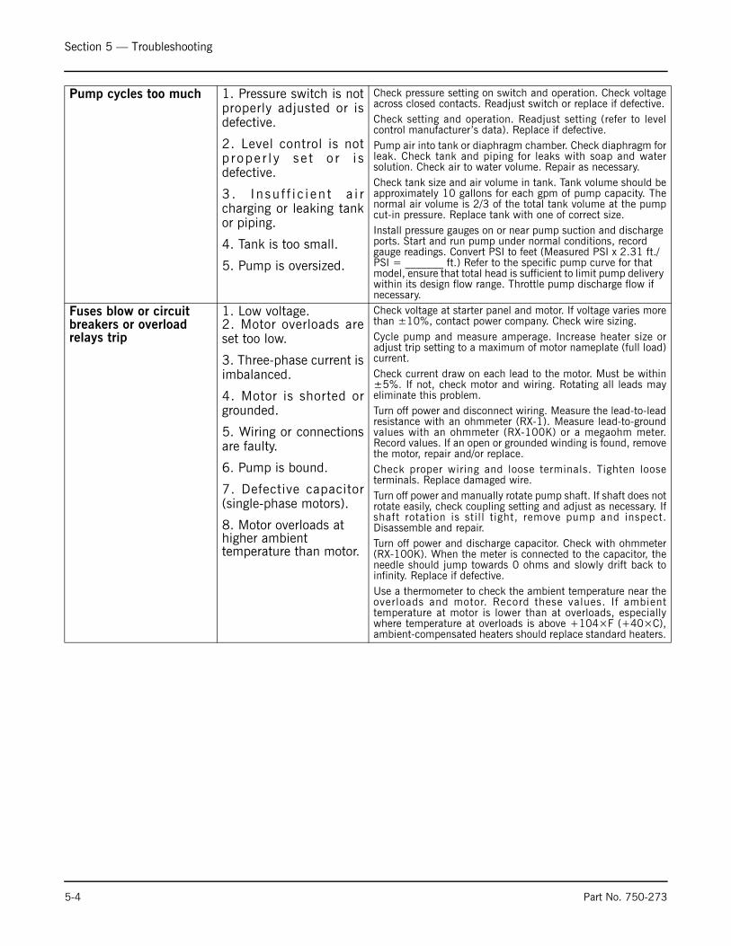
Pump cycles too much 1. Pressure switch is notproperly adjusted or isdefective.
2. Level control is notp r ope r l y s e t o r i sdefective.
3 . I n su f f i c i en t a i rcharging or leaking tankor piping.
4. Tank is too small.
5. Pump is oversized.
Check pressure setting on switch and operation. Check voltageacross closed contacts. Readjust switch or replace if defective.Check setting and operation. Readjust setting (refer to levelcontrol manufacturer’s data). Replace if defective.Pump air into tank or diaphragm chamber. Check diaphragm forleak. Check tank and piping for leaks with soap and watersolution. Check air to water volume. Repair as necessary.Check tank size and air volume in tank. Tank volume should beapproximately 10 gallons for each gpm of pump capacity. Thenormal air volume is 2/3 of the total tank volume at the pumpcut-in pressure. Replace tank with one of correct size.Install pressure gauges on or near pump suction and discharge ports. Start and run pump under normal conditions, record gauge readings. Convert PSI to feet (Measured PSI x 2.31 ft./PSI = _______ ft.) Refer to the specific pump curve for that model, ensure that total head is sufficient to limit pump delivery within its design flow range. Throttle pump discharge flow if necessary.
Fuses blow or circuit breakers or overload relays trip
1. Low voltage.2. Motor overloads areset too low.
3. Three-phase current isimbalanced.
4. Motor is shorted orgrounded.
5. Wiring or connectionsare faulty.
6. Pump is bound.
7. Defective capacitor(single-phase motors).
8. Motor overloads at higher ambient temperature than motor.
Check voltage at starter panel and motor. If voltage varies morethan ±10%, contact power company. Check wire sizing.Cycle pump and measure amperage. Increase heater size oradjust trip setting to a maximum of motor nameplate (full load)current.Check current draw on each lead to the motor. Must be within±5%. If not, check motor and wiring. Rotating all leads mayeliminate this problem.Turn off power and disconnect wiring. Measure the lead-to-leadresistance with an ohmmeter (RX-1). Measure lead-to-groundvalues with an ohmmeter (RX-100K) or a megaohm meter.Record values. If an open or grounded winding is found, removethe motor, repair and/or replace.Check proper wiring and loose terminals. Tighten looseterminals. Replace damaged wire.Turn off power and manually rotate pump shaft. If shaft does notrotate easily, check coupling setting and adjust as necessary. Ifshaft rotation is still tight, remove pump and inspect.Disassemble and repair.Turn off power and discharge capacitor. Check with ohmmeter(RX-100K). When the meter is connected to the capacitor, theneedle should jump towards 0 ohms and slowly drift back toinfinity. Replace if defective.Use a thermometer to check the ambient temperature near theoverloads and motor. Record these values. If ambienttemperature at motor is lower than at overloads, especiallywhere temperature at overloads is above +104×F (+40×C),ambient-compensated heaters should replace standard heaters.

Section 5 — Troubleshooting
Part No. 750-273 5-5
5.3.High Water Alarm Series 63 McDonnell & Miller
5.4.Low Water Cutoff Series 64 McDonnell & Miller
Problem: Burner does not shut off on low water.Cause Test Solution
Float chamber is loaded with mud or sediment.
With water level below the control check if terminals C and N.C. are open. If not, remove switch and manually test if terminals C and N.C. can be opened.
Open float chamber and clean. At this time, check for a build-up of scale or sediment between corrugations of the bellows.
Contacts are fused together. Remove switch and operate manually to verify proper switch operation.
Replace switch. Check electrical load and make sure it is within the ratings of the switch.
Problem: Burner does not shut off on low water.Cause Test Solution
Float chamber is loaded with mud or sediment.
With water level below the control check if terminals 1 and 2 are open. If not, remove switch and manually test if terminals 1 and 2 can be opened.
Open float chamber and clean. At this time, check for a build-up of scale or sediment between corrugations of the bellows.
Contacts are fused together. Remove switch and operate manually to verify proper switch operation.
Replace switch. Check electrical load and make sure it is within the ratings of the switch.
Problem: Electric water feeder does not shut off.Cause Test Solution
Build-up of scale or sediment between corrugations of the bellows.
With water level above the control, check if terminals 3 and 4 are open. If not, remove switch and manually test to verify terminals 3 and 4 can be opened.
Open float chamber and replace or clean the bellows.
Contacts are fused together. Remove switch and operate manually to verify proper switch operation.
Replace switch. Check electrical load and make sure it is within the ratings of the switch.

Section 5 — Troubleshooting
5-6 Part No. 750-273
5.5.Low Water Cutoff Series 93/193 McDonnell & Miller
Common symptoms of a problem with the control include pumpand/or burner switches not switching at proper levels. Refer to thefollowing list of items to check if the control is not operatingproperly.
1. Float Ball is Crushed
Crushed floats are typically caused by improper blowdown. Drainpiping from blowdown valve to drain should be checked for properpitch and the blowdown procedure followed when blowing downthe control. Purchase and install a new float ball after investigatingand correcting the problem.
2. Float Ball is Filled with Water
The seam weld on the float can sometimes deteriorate. This can becaused by the type of chemical treatment used in the deaerator.While this is a rare occurrence, the chemical treatment suppliershould be consulted to determine if a reaction could occur. Purchaseand install a new float ball after investigating and correcting theproblem.
3. Float Arm Springs are Bent
The pivot springs located on either side of the float rod should beflat and straight. If they become bent, the usual cause ismishandling of the unit during installation or improper blowdown.The control should never be picked up by the float ball or allowedto hang from the bowl by the float. Drain piping from blowdownvalve to drain should be checked for proper pitch and the blowdownprocedure followed when blowing down control. Purchase andinstall new control or head mechanism after investigating andcorrecting the problem.
4. Switch Contact Springs Broken
The contact springs can break if the electrical rating is exceeded.Purchase and install new switch assembly or head mechanism afterinvestigating and correcting the problem.
5. Switch Contact Springs Misaligned
Misalignment of the contact arms is usually associated with damageto the control during shipment or installation. Purchase and installnew switch assembly or head mechanism after investigating andcorrecting the problem.
6. Internal (Wetted) Parts Dirty
The internal parts can operate improperly if dirt, scale or rust isallowed to build. This condition can be a result of not blowing downthe control as recommended and/or improper boiler water chemicaltreatment. Purchase and install new control or head mechanismafter investigating and correcting the problem.

Milwaukee, Wisconsin
www.cleaver-brooks.com
Section 6Parts
Standard Traymaster Parts . . . . . . . . . . . . . . . . . . . . . . . . . . . . . . . . . . . 2Manway Cover Assemblies . . . . . . . . . . . . . . . . . . . . . . . . . . . . . . . . . . . 2Pressure Reducing Valves (Fisher 92 Series) . . . . . . . . . . . . . . . . . . . . . . . 2Pressure Reducing Valves (Spence ED Series) . . . . . . . . . . . . . . . . . . . . . . 3Pressure Reducing Valves (Spence E2D Series) . . . . . . . . . . . . . . . . . . . . . 3Valve Sets for Gauge Glass . . . . . . . . . . . . . . . . . . . . . . . . . . . . . . . . . . . 4Overflow Drainer (Steam Trap) . . . . . . . . . . . . . . . . . . . . . . . . . . . . . . . . 4Siemens Actuator Series 599 . . . . . . . . . . . . . . . . . . . . . . . . . . . . . . . . . 5Siemens Actuator Series 599 . . . . . . . . . . . . . . . . . . . . . . . . . . . . . . . . . 6Wiring Diagram for use with Siemens Actuator Series 599 . . . . . . . . . . . . . 7Make-Up Controls (Lever Operated Make-Up Valves) (Fisher 171L) . . . . . . . 8Make-Up Controls (Lever Operated Make-Up Valves) (Fisher 670EK) . . . . . . 8Make-Up Controls (Lever Operated Make-Up Valves) (Fisher 608EK)) . . . . . 8Make-Up Controls (Diaphragm Operated Make-Up Valves) (Fisher 657ES) . . 8Spray Valve . . . . . . . . . . . . . . . . . . . . . . . . . . . . . . . . . . . . . . . . . . . . . . 9Tray Assembly . . . . . . . . . . . . . . . . . . . . . . . . . . . . . . . . . . . . . . . . . . . . 9Manway Assembly, 16" Davited, 50# D.P. . . . . . . . . . . . . . . . . . . . . . . . 10Manway Assembly, 18" Davited, 50# D.P. . . . . . . . . . . . . . . . . . . . . . . . 11Manway Assembly, 20" Davited, 50# D.P. . . . . . . . . . . . . . . . . . . . . . . . 12Manway Assembly, 24" Davited, 50# D.P. . . . . . . . . . . . . . . . . . . . . . . . 13Manway Assembly, 28" Davited, 50# D.P. . . . . . . . . . . . . . . . . . . . . . . . 14Manway Assembly, 32" Davited, 50# D.P. . . . . . . . . . . . . . . . . . . . . . . . 15Manway Assembly, 36" Davited, 50# D.P. . . . . . . . . . . . . . . . . . . . . . . . 16
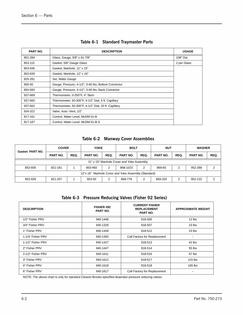
Section 6 — Parts
6-2 Part No. 750-273
PART NO. DESCRIPTION USAGE
851-284 Glass, Gauge, 5/8" x 61-7/8" 108" Dia
853-115 Gasket, 5/8" Gauge Glass 2 per Glass
853-936 Gasket, Manhole, 11" x 15"
853-939 Gasket, Manhole, 12" x 16"
825-281 Set, Water Gauge
950-50 Gauge, Pressure, 4-1/2", 0-60 lbs, Bottom Connector
850-583 Gauge, Pressure, 4-1/2", 0-60 lbs, Back Connector
937-669 Thermometer, 0-250°F, 4" Stem
937-660 Thermometer, 50-300°F, 4-1/2" Dial, 5 ft. Capillary
937-662 Thermometer, 50-300°F, 4-1/2" Dial, 20 ft. Capillary
934-322 Valve, Auto -Vent, 1/2"
817-161 Control, Water Level, McDM-51-B
817-187 Control, Water Level, McDM-51-B-S
Table 6-1 Standard Traymaster Parts
DESCRIPTION FISHER #92 PART NO.
CURRENT FISHER REPLACEMENT
PART NO.APPROXIMATE WEIGHT
1/2" Fisher PRV 940-1448 918-505 12 lbs
3/4" Fisher PRV 940-1329 918-507 23 lbs
1" Fisher PRV 940-1449 918-512 23 lbs
1-1/4" Fisher PRV 940-1355 Call Factory for Replacement -
1-1/2" Fisher PRV 940-1427 918-513 42 lbs
2" Fisher PRV 940-1447 918-514 55 lbs
2-1/2" Fisher PRV 940-1611 918-516 67 lbs
3" Fisher PRV 940-1612 918-517 115 lbs
4" Fisher PRV 940-1618 918-518 165 lbs
6" Fisher PRV 940-1617 Call Factory for Replacement -
NOTE: The above chart is only for standard Cleaver-Brooks specified deaerator pressure reducing valves.
Table 6-3 Pressure Reducing Valves (Fisher 92 Series)
Gasket PART NO.COVER YOKE BOLT NUT WASHER
PART NO. REQ. PART NO. REQ. PART NO. REQ. PART NO. REQ. PART NO. REQ.
11" x 15" Manhole Cover and Yoke Assembly
853-936 821-191 1 953-460 2 868-1023 2 869-65 2 952-288 2
12"x 16" Manhole Cover and Yoke Assembly (Standard)
853-939 821-207 1 953-50 2 868-778 2 869-320 2 952-132 2
Table 6-2 Manway Cover Assemblies
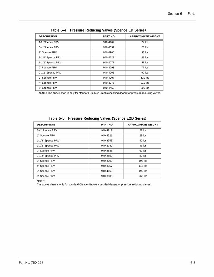
Section 6 — Parts
Part No. 750-273 6-3
DESCRIPTION PART NO. APPROXIMATE WEIGHT
1/2" Spence PRV 940-4904 24 lbs
3/4" Spence PRV 940-4339 28 lbs
1" Spence PRV 940-4905 33 lbs
1-1/4" Spence PRV 940-4722 43 lbs
1-1/2” Spence PRV 940-4077 53 lbs
2” Spence PRV 940-3298 77 lbs
2-1/2" Spence PRV 940-4906 92 lbs
3" Spence PRV 940-4907 120 lbs
4" Spence PRV 940-3976 210 lbs
5" Spence PRV 940-4450 290 lbs
NOTE: The above chart is only for standard Cleaver-Brooks specified deaerator pressure reducing valves.
Table 6-4 Pressure Reducing Valves (Spence ED Series)
DESCRIPTION PART NO. APPROXIMATE WEIGHT
3/4" Spence PRV 940-4919 28 lbs
1" Spence PRV 940-3321 29 lbs
1-1/4" Spence PRV 940-4358 40 lbs
1-1/2" Spence PRV 940-2740 46 lbs
2" Spence PRV 940-2885 67 lbs
2-1/2" Spence PRV 940-2859 80 lbs
3" Spence PRV 940-3390 108 lbs
4" Spence PRV 940-3357 145 lbs
5" Spence PRV 940-4069 195 lbs
6" Spence PRV 940-3303 260 lbs
NOTE:The above chart is only for standard Cleaver-Brooks specified deaerator pressure reducing valves.
Table 6-5 Pressure Reducing Valves (Spence E2D Series)
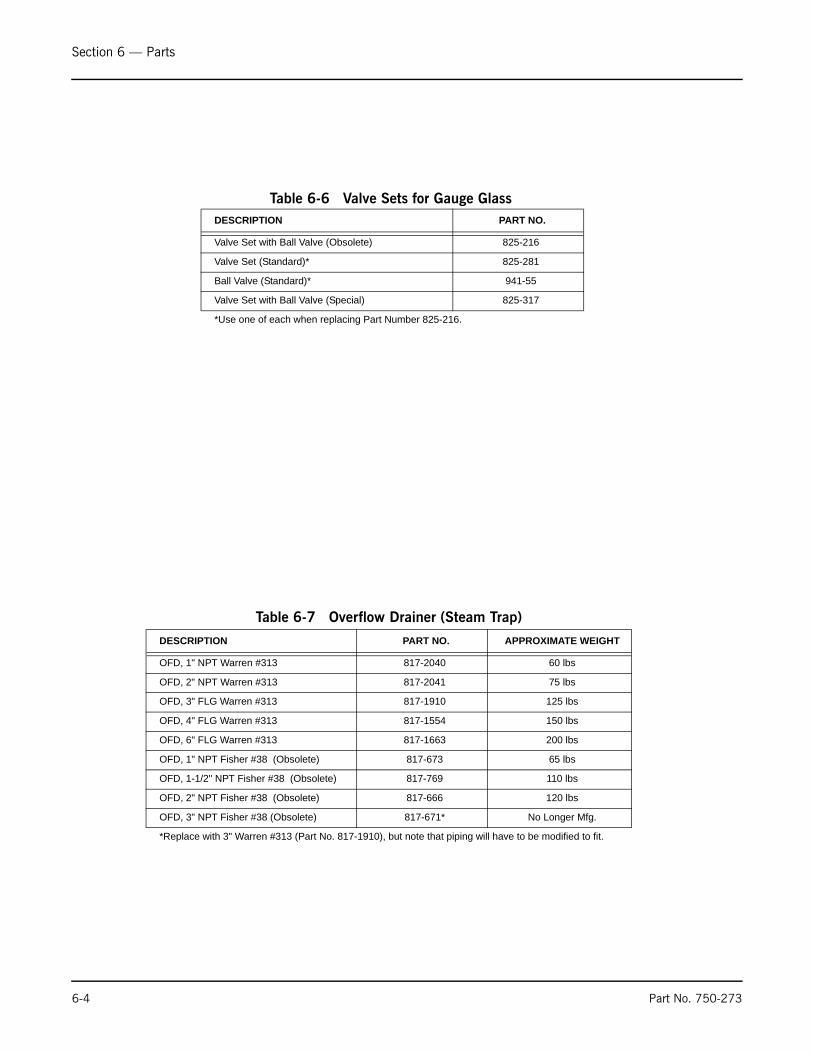
Section 6 — Parts
6-4 Part No. 750-273
DESCRIPTION PART NO. APPROXIMATE WEIGHT
OFD, 1" NPT Warren #313 817-2040 60 lbs
OFD, 2" NPT Warren #313 817-2041 75 lbs
OFD, 3" FLG Warren #313 817-1910 125 lbs
OFD, 4" FLG Warren #313 817-1554 150 lbs
OFD, 6" FLG Warren #313 817-1663 200 lbs
OFD, 1" NPT Fisher #38 (Obsolete) 817-673 65 lbs
OFD, 1-1/2" NPT Fisher #38 (Obsolete) 817-769 110 lbs
OFD, 2" NPT Fisher #38 (Obsolete) 817-666 120 lbs
OFD, 3" NPT Fisher #38 (Obsolete) 817-671* No Longer Mfg.
*Replace with 3" Warren #313 (Part No. 817-1910), but note that piping will have to be modified to fit.
Table 6-7 Overflow Drainer (Steam Trap)
DESCRIPTION PART NO.
Valve Set with Ball Valve (Obsolete) 825-216
Valve Set (Standard)* 825-281
Ball Valve (Standard)* 941-55
Valve Set with Ball Valve (Special) 825-317
*Use one of each when replacing Part Number 825-216.
Table 6-6 Valve Sets for Gauge Glass

Section 6 — Parts
Part No. 750-273 6-5
DEAERATOR CHART-MAXIMUM WATER CAPACITY-U.S. GALLONS PER MINUTE
1-1/2
2 40
25
1-1/4
3/4
1
1/2
6.3
16
10
4 12.6
79
126.4 155
97
200
125
15.5
24.419.9
31.6
50.6
38.7
62
31.5
80
50
20
NUMBERPART
SIZE INVALVE
INCHESCV
FEEDWATER VALVE INLET PRESSURE - PSI
25 30 40
237
148
59
37
23.7
50
94.7
268
167.7
67
42
26.8
60
107.3
296.6
185.4
74
46.7
29.7
70
118.7
230.4
368.7
147.5
92
58
36.9
100
941-02575
941-02574
941-02573
941-02572
941-02571
941-02570
DEAERATORS WITH SIEMENS VALVES SIZES 1/2" THRU 1-1/4" AREUSED WITH ACTUATOR PART NUMBER 945-00222.DEAERATORS WITH SIEMENS VALVES SIZES 1-1/2" AND 2" ARE
USED WITH ACTUATOR PART NUMBER 945-00240.
WHEN MAKE-UP WATER IS FED DIRECTLY TO THE DEAERATOR, THE SIZE AND CAPACITY ARE DEPENDANT ON INLETWATER PRESSURE. TO SELECT VALVE SIZE, FIRST DETERMINE MAKE-UP REQUIREMENT. THEN SELECT A VALVE WITH ADEQUATE CAPACITY AT THE MINIMUM SUPPLY PRESSURE.
EXAMPLE: TOTAL LOAD = 45,000 LB/HR (90 GPM) MAKE-UP = 50% OR 22,500 LB/HR (45 GPM) SUPPLY PRESSURE IS 40 PSIG TO 60 PSIG SELECT A 1" VALVE WHICH WILL PASS 45 GPM MINIMUM @ 40 PSIG.
A THREE VALVE BYPASS AROUND THE MAKE-UP VALVE ALONG WITH AN INLET STRAINER IS RECOMMENDED.
WHEN VALVE IS USED ON DEAERATOR IN A TWO-TANK SYSTEM OR DUO-TANK SYSTEM, ENTIRE LOAD IS PASSEDTHROUGH VALVE. SELECT VALVE SIZE BASED ON TOTAL CAPACITY AT 25 PSIG SUPPLY PRESSURE.
EXAMPLE: TOTAL LOAD = 45,000 LB/HR (90 GPM) SELECT A 2" VALVE THAT WILL PASS 90 GPM MINIMUM @ 25 PSI INLET PRESSURE.
NOTE: TABLE IS BASED ON DEAERATOR OPERATING PRESSURE OF 5 PSI WITH
**
2) ACTUATOR AUXILIARY SWITCH SPDT INDICATES ZERO STROKE POSITION P/N 836-1339 MAY BE REQUIRED FOR SPECIFIC CUSTOMER CONNECTIONS (SEE WIRING DRAWING SHEET 4).
POWER SUPPLY P/N 832-02179 IN ADDITION TO USING P/N 832-00235.
1) ALL ACTUATORS REQUIRE 24 VDC TRANSFORMER P/N 832-00235, USED WITH LEVEL MASTER AND
3) McDONALD MILLER REQUIRES THE USE OF A 10-12 VDC
McDONNELL MILLER LWCO.
GENERAL NOTES:
* A WATER SPRAY HEAD PRESSURE DROP OF 7-10 PSI. THE SIEMENS FEEDWATER VALVE SELECTION IS BASED ON A VALVE PRESSURE DROPOF 10 PSI @ AT 25 PSI FEEDWATER INLET PRESSURE.
Table 6-8 Siemens Actuator Series 599

Section 6 — Parts
6-6 Part No. 750-273
VALVEACTION
Female NPT by
A A
B
C
Female NPT F X F
VALVESIZE
INCHES
A
FxF
1/2 1-7/16 3-13/16
B C
2-3/16
2-3/163-13/161-11/163/4
2-3/163-13/1621
2-3/163-13/162-1/21-1/4
2-1/43-7/82-9/161-1/2
2-9/164-1/23-1/82
CLOSEDNORMALLY
ASSEMBLYVALVE
WEIGHT
5
4
3
8
7
16
2.2
5 10
3.2
20
4.5 5.0 5.5
25 30
6.3
40
DIFFERENTIAL - PSIPRESSUREVALVE
SIZE ININCHES
1/2941-2567
PARTNUMBER
10.1
15.8
25
40
63
101
158
253
8.88.07.25.13.61/2941-2568
13.712.511.27.95.61/2941-2569
21.920.017.912.68.91/2941-2570
3532282014.13/4941-2571
55504532221941-2572
88807251361-1/4941-2573
13712511279561-1/2941-2574
219200179126892941-2575
2-WAY VALVE DIMENSIONS
SIEMENS FEEDWATER VALVE-MAXIMUM WATER CAPACITY-U.S. GALLONS PER MINUTE
CV
1.0
1.6
2.5
4
6.3
10
16
25
40
Table 6-9 Siemens Actuator Series 599

Section 6 — Parts
Part No. 750-273 6-7
Table 6-10 Wiring Diagram for use with Siemens Actuator Series 599

Section 6 — Parts
6-8 Part No. 750-273
DESCRIPTION PART NO. APPROXIMATE WEIGHT DESCRIPTION* PART NO.
Make-Up Valve, Lever Operated 1/2" 940-3539 8 lbs Repair Kit for 171L 3/8" thru 3/4" 797-04052
Make-Up Valve, Lever Operated 3/4" 940-3540 8 lbs Repair Kit for 171L 3/8" thru 3/4" 797-04052
Make-Up Valve, Lever Operated 1" 940-3541 8 lbs Repair Kit for 171L 1" 797-04053
Make-Up Valve, Lever Operated 1-1/4" 940-3542 19 lbs Repair Kit for 171L 1-1/4" and 1-1/2" 797-04054
Make-Up Valve, Lever Operated 1-1/2" 940-3543 25 lbs Repair Kit for 171L 1-1/4" and 1-1/2" 797-04054
Make-Up Valve, Lever Operated 2" 940-3544 30 lbs Repair Kit for 171L 2" 797-04055
* Kits include O-ring, seat ring, pilot valve assembly, packing, piston rinr, and expander.
Table 6-11 Make-Up Controls (Lever Operated Make-Up Valves) (Fisher 171L)
DESCRIPTION PART NO.
Make-Up Valve, Lever Operated 2-1/2" FLG 940-4697
Make-Up Valve, Lever Operated 3" FLG 940-4781
Make-Up Valve, Lever Operated 4" FLG 940-4580
Table 6-13 Make-Up Controls (Lever Operated Make-Up Valves) (Fisher 608EK))
DESCRIPTION PART NO.
Make-Up Valve, Lever Operated 1" NPT 940-4894
Make-Up Valve, Lever Operated 1-1/2" NPT 940-4474
Make-Up Valve, Lever Operated 2-1/2" FLG 940-5193
Make-Up Valve, Lever Operated 3" 940-4278
Make-Up Valve, Lever Operated 4" 940-4320
Table 6-12 Make-Up Controls (Lever Operated Make-Up Valves) (Fisher 670EK)
DESCRIPTION PART NO.
Make-Up Valve, Diaphragm Operated 1/2" NPT 940-4520
Make-Up Valve, Diaphragm Operated 3/4" NPT 940-4632
Make-Up Valve, Diaphragm Operated 1" PT 940-4081
Make-Up Valve, Diaphragm Operated 1-1/2" NPT 940-3849
Make-Up Valve, Diaphragm Operated 2" NPT 940-4660
Make-Up Valve, Diaphragm Operated 2-1/2" FLG 940-4555
Make-Up Valve, Diaphragm Operated 3" FLG 940-4684
NOTE: Shown is a typical 657 diaphragm actuator mounted on an ES valve.
Table 6-14 Make-Up Controls (Diaphragm Operated Make-Up Valves) (Fisher 657ES)

Section 6 — Parts
Part No. 750-273 6-9
DESCRIPTIONPART NO.QTYITEM
COUPLING, FULL, 2 1/2" NPT 150#, 316L SS858-00341-00011
BULK PLATE, 1/2" X 3-1/4" DIA.,316L SS976-00058-00012
BULK PLATE, 1/4" X 1-5/8" DIA., 316L SS976-00109-00013
BULK PLATE, 1/4" X 3/4" X 2-3/4" LG., 316L SS976-00109-00014
BULK THREAD STOCK, 3/8-24 UNF X 3-5/8" LG., 316 SS841-01872-00015
SPRING, COMPRESSION, 1-1/2" DIA. X 3/16" X 1-7/8" LG., 316 SS082-00754-00016
NUT, HEX, 3/8-24 UNF, 316 SS869-00367-00017
2
5
1 4
6
3
7
Table 6-15 Spray Valve
Table 6-16 Tray Assembly
Tray Size Part No.36” 275-0030024” 275-0029818” 275-00297

Section 6 — Parts
6-10 Part No. 750-273
Table 6-17 Manway Assembly, 16" Davited, 50# D.P.

Section 6 — Parts
Part No. 750-273 6-11
Table 6-18 Manway Assembly, 18" Davited, 50# D.P.

Section 6 — Parts
6-12 Part No. 750-273
QTY
123456
11
2111
029-01778029-02012
603-01384FLANGE, BLIND, 20" MANWAY, 50# F.F. (029B01761)FLANGE, RING, 20" MANWAY, 50# F.F. (029B02003)
BOLT & GASKET ASSY, 20" 50# F.F. MANWAY (603B01382)
4 5 61
FRONT VIEW SIDE VIEW
2
3
EYE BOLT, PLAIN, FORGEDWASHER, FLAT, PLATED WROUGHT STEELNUT, HEX.869-00086
952-00111841-01640
ASSEMBLY P/N 317-00131
Table 6-19 Manway Assembly, 20" Davited, 50# D.P.
DESCRIPTIONPART NO.ITEM

Section 6 — Parts
Part No. 750-273 6-13
123456
11
2111
029-01811029-02013
603-01385FLANGE, BLIND, 24" MANWAY, 50# F.F. (029B01761)FLANGE, RING, 24" MANWAY, 50# F.F. (029B02003)
BOLT & GASKET ASSY, 24" 50# F.F. MANWAY (603B01382)
4 5 6 1
FRONT VIEW SIDE VIEW
2
3
EYE BOLT, PLAIN, FORGEDWASHER, FLAT, PLATED WROUGHT STEELNUT, HEX, 1/2"-13869-00086
952-00111841-01640
ASSEMBLY P/N 317-00132
Table 6-20 Manway Assembly, 24" Davited, 50# D.P.
QTY DESCRIPTIONPART NO.ITEM

Section 6 — Parts
6-14 Part No. 750-273
123456
11
2111
029-01823029B02003
869-00086952-00111841-01640603-01386
FLANGE, BLIND, 28" MANWAY, 50# F.F. (029B01761)FLANGE, RING, 28" MANWAY, 50# F.F.
NUT, HEXWASHER, FLAT, PLATED WROUGHT STEELEYE BOLT, PLAIN, FORGEDBOLT & GASKET ASSY, 28" 50# F.F. MANWAY (603B01382)
4 5 61
FRONT VIEW SIDE VIEW
2
3
ASSEMBLY P/N 317-00133
Table 6-21 Manway Assembly, 28" Davited, 50# D.P.
QTY DESCRIPTIONPART NO.ITEM

Section 6 — Parts
Part No. 750-273 6-15
123456
11
2111
029-01825029-02014
869-00086952-00111841-01640603-01387
FLANGE, BLIND, 32" MANWAY, 50# F.F. (029B01761)FLANGE, RING, 32" MANWAY, 50# F.F. (029B02003)
NUT, HEXWASHER, FLAT, PLATED WROUGHT STEELEYE BOLT, PLAIN, FORGEDBOLT & GASKET ASSY, 32" 50# F.F. MANWAY (603B01382)
4 5 6 1
FRONT VIEW SIDE VIEW
2
3
ASSEMBLY P/N 317-00134
Table 6-22 Maway Assembly, 32" Davited, 50# D.P.
QTY DESCRIPTIONPART NO.ITEM
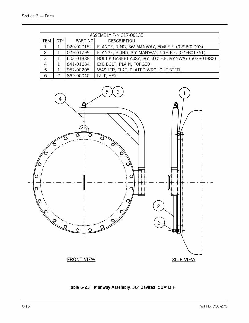
Section 6 — Parts
6-16 Part No. 750-273
123456
11
2111
029-01799029-02015
869-00040952-00205841-01684603-01388
FLANGE, BLIND, 36" MANWAY, 50# F.F. (029B01761)FLANGE, RING, 36" MANWAY, 50# F.F. (029B02003)
NUT, HEXWASHER, FLAT, PLATED WROUGHT STEELEYE BOLT, PLAIN, FORGEDBOLT & GASKET ASSY, 36" 50# F.F. MANWAY (603B01382)
45 6 1
FRONT VIEW SIDE VIEW
2
3
ASSEMBLY P/N 317-00135
Table 6-23 Manway Assembly, 36" Davited, 50# D.P.
QTY DESCRIPTIONPART NO.ITEM


e-mail: [email protected] Address: http://www.cleaverbrooks.com