trd daq status report - roma1.infn.it · thermal cycling vibration test ... - was cleaned before...
TRANSCRIPT
Wim de Boer, Chan Hoon Chung*, Florian Hauler, Andreas Sabellek, Mike Schmanau, Georg Schwering*
IEKP - Universität Karlsruhe (TH)*RWTH-Aachen I
TRDTRD DAQDAQStatus ReportStatus Report
19.10.2005 TRD-Meeting, Rom Wim de Boer / Florian Hauler , IEKP 2
OutlineOutline
1. ESS (Environmental Stress Screening) @ CSIST: (Temperature cycling, Vibration and EMI/EMC at CRATE level) on QM2 modulessuccessfull
2. Time scale / Prospect for testbeam
19.10.2005 TRD-Meeting, Rom Wim de Boer / Florian Hauler , IEKP 3
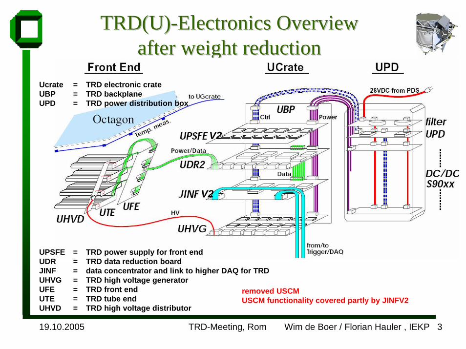
TRD(U)TRD(U)--ElectronicsElectronics OverviewOverviewafterafter weightweight reductionreduction
Ucrate = TRD electronic crateUBP = TRD backplaneUPD = TRD power distribution box
UPSFE = TRD power supply for front endUDR = TRD data reduction boardJINF = data concentrator and link to higher DAQ for TRDUHVG = TRD high voltage generatorUFE = TRD front endUTE = TRD tube endUHVD = TRD high voltage distributor
removed USCMUSCM functionality covered partly by JINFV2
V2
V2
19.10.2005 TRD-Meeting, Rom Wim de Boer / Florian Hauler , IEKP 4
Load resistors
UD
R2
digitized DAC level
DAC level
Clock ADC
DACFP
GA
/DSP
AD
CLV
DS
control signals
UFS
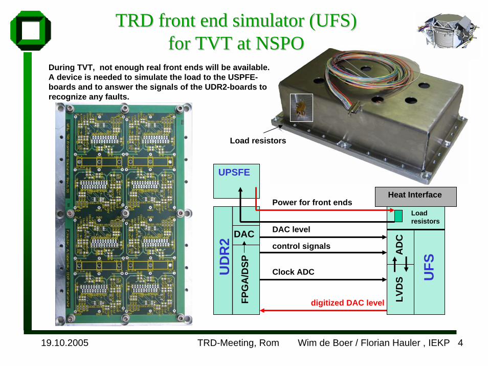
UPSFE
Power for front endsLoadresistors
Heat Interface
TRD front end TRD front end simulatorsimulator (UFS) (UFS) forfor TVT at NSPOTVT at NSPO
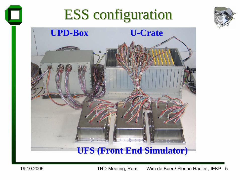
During TVT, not enough real front ends will be available.A device is needed to simulate the load to the USPFE-boards and to answer the signals of the UDR2-boards to recognize any faults.
19.10.2005 TRD-Meeting, Rom Wim de Boer / Florian Hauler , IEKP 5
ESS ESS configurationconfigurationUPD-Box U-Crate
UFS (Front End Simulator)
19.10.2005 TRD-Meeting, Rom Wim de Boer / Florian Hauler , IEKP 6
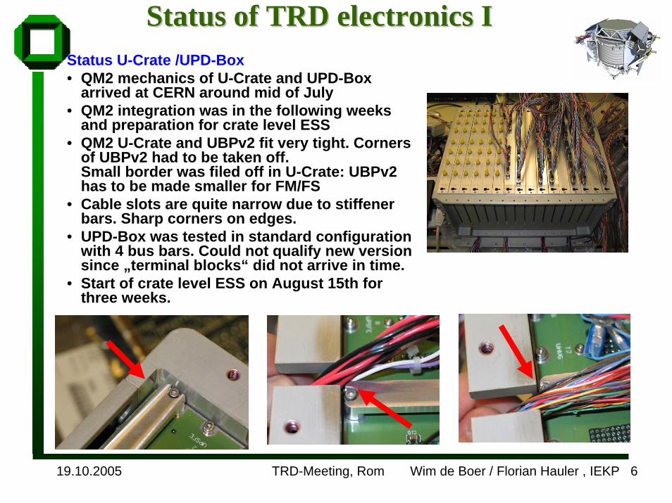
Status of Status of TRDTRD electronics Ielectronics IStatus U-Crate /UPD-Box• QM2 mechanics of U-Crate and UPD-Box
arrived at CERN around mid of July• QM2 integration was in the following weeks
and preparation for crate level ESS• QM2 U-Crate and UBPv2 fit very tight. Corners
of UBPv2 had to be taken off.Small border was filed off in U-Crate: UBPv2 has to be made smaller for FM/FS
• Cable slots are quite narrow due to stiffener bars. Sharp corners on edges.
• UPD-Box was tested in standard configuration with 4 bus bars. Could not qualify new version since „terminal blocks“ did not arrive in time.
• Start of crate level ESS on August 15th for three weeks.

19.10.2005 TRD-Meeting, Rom Wim de Boer / Florian Hauler , IEKP 7
UPDUPD--BoxBox AssemblyAssembly• Prototype UPD-Box assembled.• Electrical tests finished.• Slow control is working: DC/DC
converters can be switched on oroff.
• System was running one monthwithout amy trip in UPD-Box.
• Noise performance tested on cosmics test stand.
• Tricky cabling!!
19.10.2005 TRD-Meeting, Rom Wim de Boer / Florian Hauler , IEKP 8
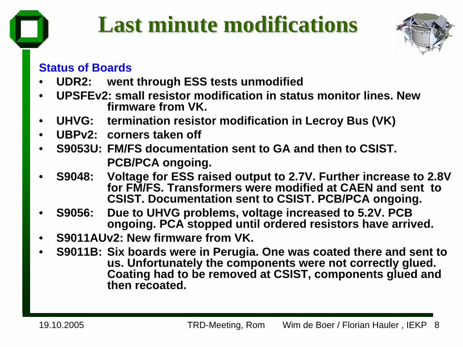
Last minute modifications Last minute modifications
Status of Boards• UDR2: went through ESS tests unmodified• UPSFEv2: small resistor modification in status monitor lines. New
firmware from VK.• UHVG: termination resistor modification in Lecroy Bus (VK)• UBPv2: corners taken off• S9053U: FM/FS documentation sent to GA and then to CSIST.
PCB/PCA ongoing.• S9048: Voltage for ESS raised output to 2.7V. Further increase to 2.8V
for FM/FS. Transformers were modified at CAEN and sent toCSIST. Documentation sent to CSIST. PCB/PCA ongoing.
• S9056: Due to UHVG problems, voltage increased to 5.2V. PCB ongoing. PCA stopped until ordered resistors have arrived.
• S9011AUv2: New firmware from VK.• S9011B: Six boards were in Perugia. One was coated there and sent to
us. Unfortunately the components were not correctly glued. Coating had to be removed at CSIST, components glued and then recoated.
19.10.2005 TRD-Meeting, Rom Wim de Boer / Florian Hauler , IEKP 9
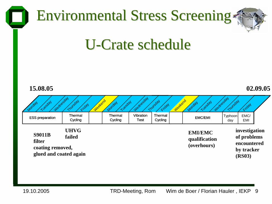
EnvironmentalEnvironmental Stress Stress ScreeningScreening
UU--CrateCrate scheduleschedule
15.08.05 02.09.05
Monda
yTue
sday
Wedne
sday
Thursd
ayFrid
ay
Weeke
ndMon
day
Tuesd
ayWed
nesd
ayThu
rsday
Friday
Weeke
ndMon
day
Tuesd
ayWed
nesd
ayThu
rsday
Friday
ESS preparation EMC/EMIThermal Cycling
Vibration Test
Thermal Cycling
Thermal Cycling
Typhoon day
EMC/EMI
ESS preparation EMC/EMIThermal Cycling
Vibration Test
Thermal Cycling
Thermal Cycling
UHVGfailed
investigationof problemsencounteredby tracker(RS03)
EMI/EMC qualification(overhours)
S9011B filtercoating removed, glued and coated again
19.10.2005 TRD-Meeting, Rom Wim de Boer / Florian Hauler , IEKP 10
Thermal Thermal CyclingCycling II
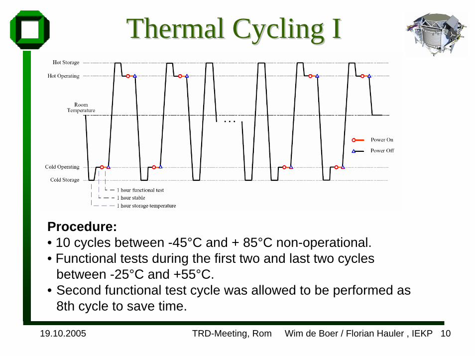
Procedure:• 10 cycles between -45°C and + 85°C non-operational.• Functional tests during the first two and last two cycles
between -25°C and +55°C.• Second functional test cycle was allowed to be performed as
8th cycle to save time.
19.10.2005 TRD-Meeting, Rom Wim de Boer / Florian Hauler , IEKP 11
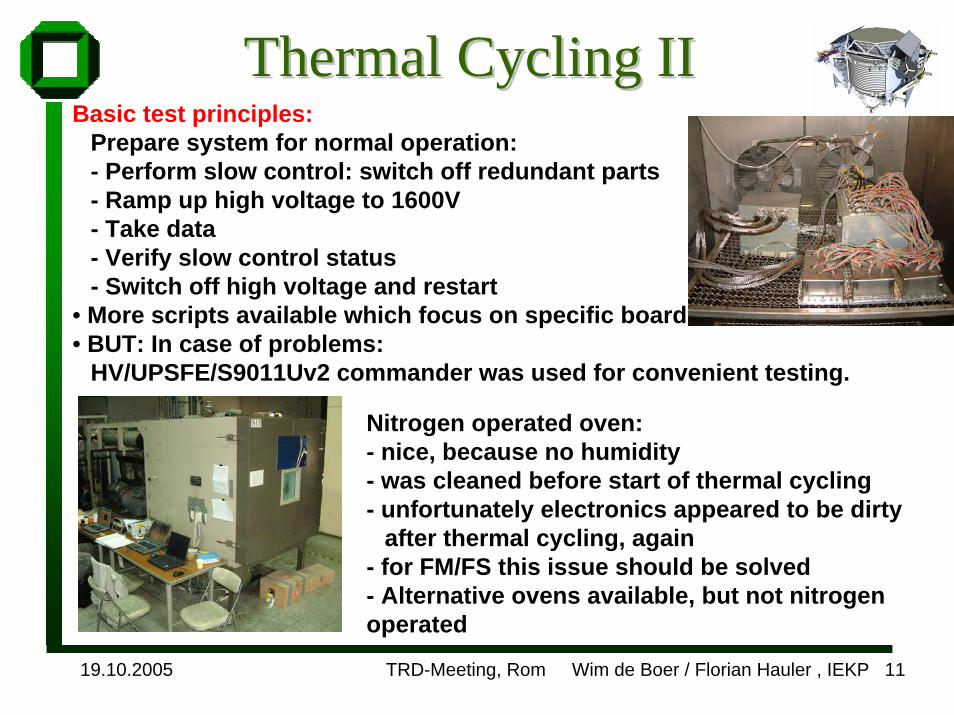
Thermal Cycling IIThermal Cycling IIBasic test principles:
Prepare system for normal operation:- Perform slow control: switch off redundant parts- Ramp up high voltage to 1600V- Take data- Verify slow control status- Switch off high voltage and restart
• More scripts available which focus on specific boards• BUT: In case of problems:
HV/UPSFE/S9011Uv2 commander was used for convenient testing.
Nitrogen operated oven:- nice, because no humidity- was cleaned before start of thermal cycling- unfortunately electronics appeared to be dirty
after thermal cycling, again- for FM/FS this issue should be solved- Alternative ovens available, but not nitrogen operated

19.10.2005 TRD-Meeting, Rom Wim de Boer / Florian Hauler , IEKP 12
Thermal Cycling IIIThermal Cycling IIIMajor observations:• On first cycle: problems with UHVG 92010: 1 HV channel trips
@ -25°C; Channel works again after heating up. Board replaced with 92008. Had to start again thermal cycling.
• At low temperatures JINF seems to get problems recognizing all UDR2s automatically. Had to set JINF mask manually in order to access all UDR2s. With that modification, the system worked ok.
• At -25°C UPSFEv2 recognizes UHVG trips when switching off S9056 DC/DC converter.
• So far no major problems, however system seems to like warmer environment more than the cold one…
19.10.2005 TRD-Meeting, Rom Wim de Boer / Florian Hauler , IEKP 13
Thermal Thermal CyclingCycling IVIV
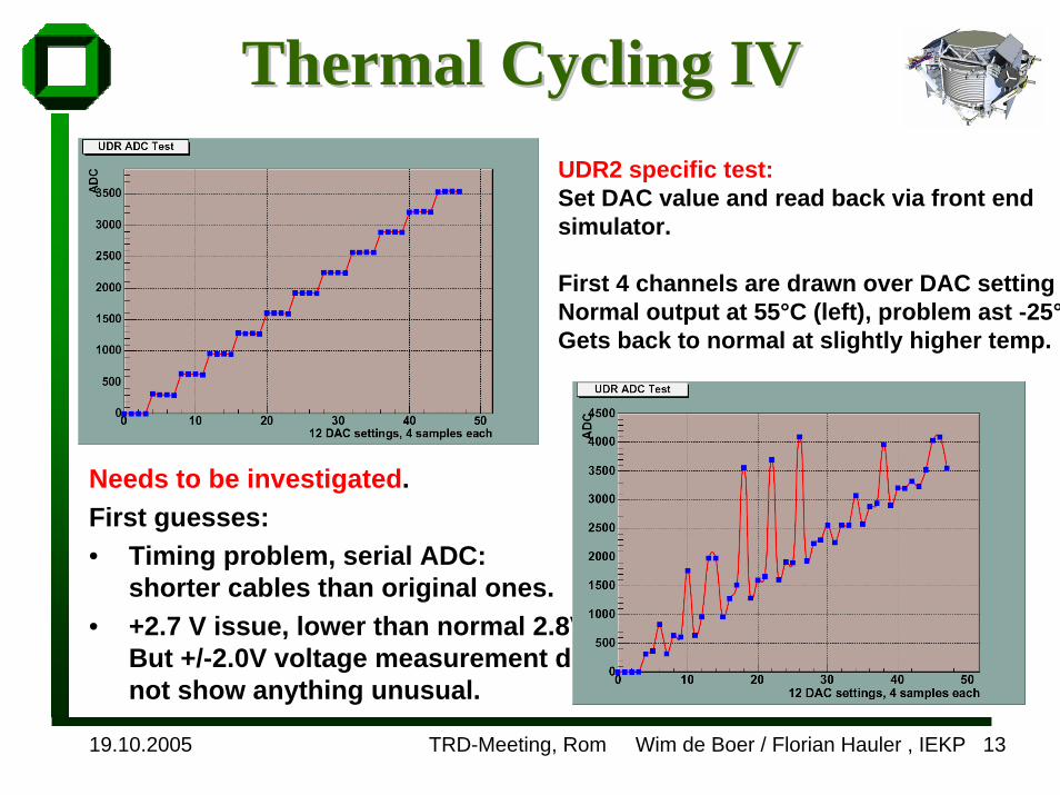
Needs to be investigated.First guesses:• Timing problem, serial ADC:
shorter cables than original ones.• +2.7 V issue, lower than normal 2.8V
But +/-2.0V voltage measurement didnot show anything unusual.
UDR2 specific test:Set DAC value and read back via front end simulator.
First 4 channels are drawn over DAC settingNormal output at 55°C (left), problem ast -25°Gets back to normal at slightly higher temp.

19.10.2005 TRD-Meeting, Rom Wim de Boer / Florian Hauler , IEKP 14
Vibration test Vibration test • Procedure:
- Test UPD-Box and U-Crate separately, but still connected to each other.- Front end simulator was attached to verify connectors (made setupcomplicated).
• Observations:- After z-vibration HV channel A3 of UHVG 92013 stopped working. ADC readout was permanently 0.- Decision was taken to continue and not to exchange the board, since thiswould have caused a restart of thermal cycling.- observed one power glitch after X-vibration of UPD. Test-Script hangs. Power cycle restores functionality.
19.10.2005 TRD-Meeting, Rom Wim de Boer / Florian Hauler , IEKP 15
Second thermal Second thermal cyclingcycling II
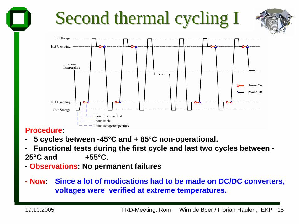
Procedure: - 5 cycles between -45°C and + 85°C non-operational.- Functional tests during the first cycle and last two cycles between -25°C and +55°C. - Observations: No permanent failures
- Now: Since a lot of modications had to be made on DC/DC converters, voltages were verified at extreme temperatures.

19.10.2005 TRD-Meeting, Rom Wim de Boer / Florian Hauler , IEKP 16
Second thermal Second thermal cyclingcycling IIII
• Voltage measurement on power bus of backplane and UFS in order to verify DC/DC convertervoltages:
• Used Keithley 2000 with scannercard and GPIB readout.
• No special observations, everything seems to be ok.
One DC/DC half S9053U S9056 S9056+3,4V +5,2V +5,2V -2,7V +2,7V -2,7V +2,7V -2,0V +2,0V
-25°C 3,329 5,25 5,249 -2,639 2,705 -2,673 2,735 -1,97 1,994+55°C 3,418 5,162 5,172 -2,614 2,698 -2,652 2,732 -1,961 1,987
Both DC/DC halves S9053U S9056 S9056+3,4V +5,2V +5,2V -2,7V +2,7V -2,7V +2,7V -2,0V +2,0V
-25°C 3,348 5,258 5,257 -2,647 2,716 -2,713 2,712 -1,973 1,995+55°C 3,445 5,161 5,172 -2,637 2,699 -2,703 2,71 -1,964 1,988
S9048 S9048 UFS
S9048 S9048 UFS

19.10.2005 TRD-Meeting, Rom Wim de Boer / Florian Hauler , IEKP 17
EMI/EMC EMI/EMC preparationpreparation IIStarting basis: Tracker problems. First, try to show that system can work
in a specific configuration, then try to reproduce Tracker problemsPreparations:• armor shielded cables• shielding of U-Crate: cover connectors and holes with Aluminum tape• 0.9m x 0.9m Aluminum radiator simulation plate of 1cm thickness
made by CSIST to provide realistic grounding, comparable to theexperiment. Plate grounded on a single-point to the copper table.
19.10.2005 TRD-Meeting, Rom Wim de Boer / Florian Hauler , IEKP 18
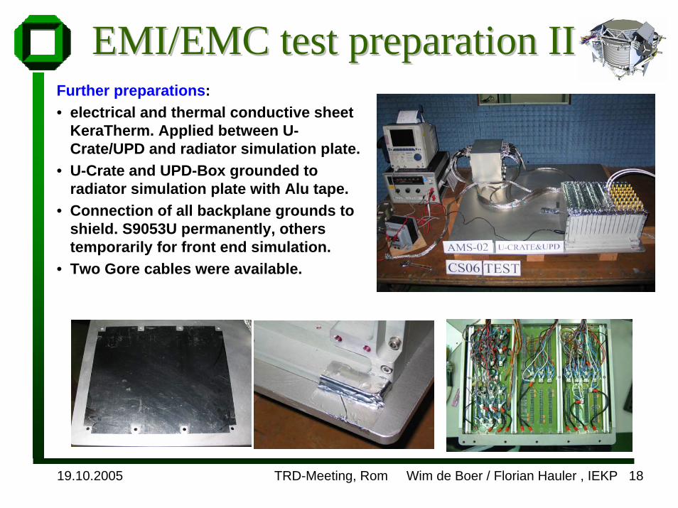
EMI/EMC test EMI/EMC test preparationpreparation IIIIFurther preparations:• electrical and thermal conductive sheet
KeraTherm. Applied between U-Crate/UPD and radiator simulation plate.
• U-Crate and UPD-Box grounded to radiator simulation plate with Alu tape.
• Connection of all backplane grounds to shield. S9053U permanently, otherstemporarily for front end simulation.
• Two Gore cables were available.
19.10.2005 TRD-Meeting, Rom Wim de Boer / Florian Hauler , IEKP 19
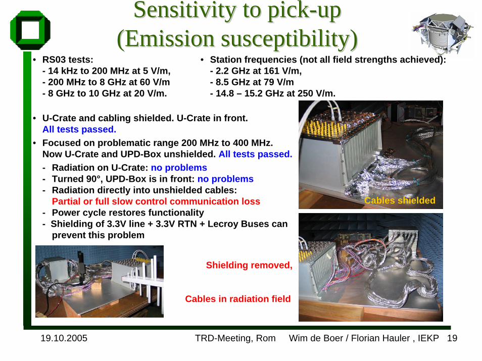
• RS03 tests: - 14 kHz to 200 MHz at 5 V/m, - 200 MHz to 8 GHz at 60 V/m - 8 GHz to 10 GHz at 20 V/m.
• U-Crate and cabling shielded. U-Crate in front. All tests passed.
• Focused on problematic range 200 MHz to 400 MHz. Now U-Crate and UPD-Box unshielded. All tests passed.- Radiation on U-Crate: no problems- Turned 90°, UPD-Box is in front: no problems- Radiation directly into unshielded cables:
Partial or full slow control communication loss- Power cycle restores functionality- Shielding of 3.3V line + 3.3V RTN + Lecroy Buses can
prevent this problem
• Station frequencies (not all field strengths achieved): - 2.2 GHz at 161 V/m, - 8.5 GHz at 79 V/m- 14.8 – 15.2 GHz at 250 V/m.
Cables shielded
Sensitivity to pickSensitivity to pick--upup(Emission susceptibility)(Emission susceptibility)
Shielding removed,
Cables in radiation field
19.10.2005 TRD-Meeting, Rom Wim de Boer / Florian Hauler , IEKP 20
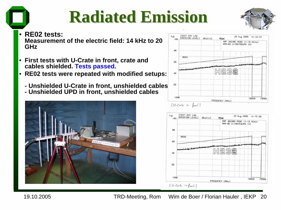
RadiatedRadiated Emission Emission • RE02 tests:
Measurement of the electric field: 14 kHz to 20 GHz
• First tests with U-Crate in front, crate and cables shielded. Tests passed.
• RE02 tests were repeated with modified setups:
- Unshielded U-Crate in front, unshielded cables- Unshielded UPD in front, unshielded cables
19.10.2005 TRD-Meeting, Rom Wim de Boer / Florian Hauler , IEKP 21
Summary pickSummary pick--up sensitivityup sensitivityWhat do the tests mean:• With copper armor shielding the system works perfectly.• Without copper shielding on cables the system gets influenced
between 200 and 400 MHz. Lecroy buses get affected. Lecroycommunication lost.
• Copper armor on 3.3V line, 3.3VRTN and Lecroy lines help to avoid this problem
: What the tests do NOT mean Shielding of 3.3V line, 3.3VRTN and Lecroy lines is sufficient. =>Physics performance (noise) was not tested.
• Problems are absolutely identical to the Tracker problems. => We had no randomly switching DC/DC converters.
----• Shielding could impose a weight problem. If we decide not to
shield, we should test extensively the performance on the assembled detector. Is there any antenna on the ISS pointed in our direction?
19.10.2005 TRD-Meeting, Rom Wim de Boer / Florian Hauler , IEKP 22
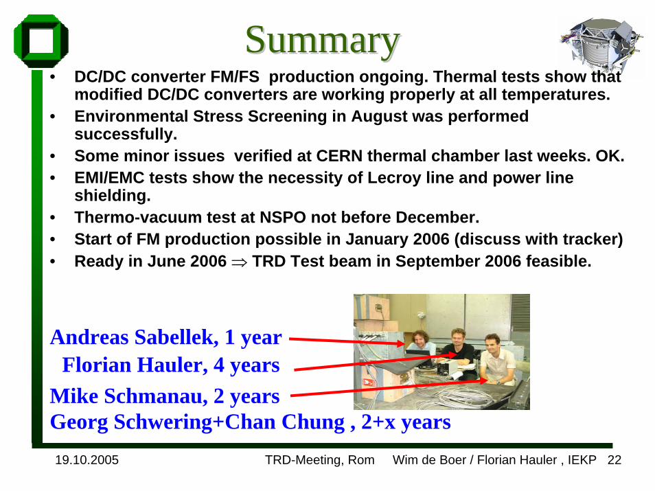
SummarySummary• DC/DC converter FM/FS production ongoing. Thermal tests show that
modified DC/DC converters are working properly at all temperatures.• Environmental Stress Screening in August was performed
successfully.• Some minor issues verified at CERN thermal chamber last weeks. OK.• EMI/EMC tests show the necessity of Lecroy line and power line
shielding.• Thermo-vacuum test at NSPO not before December.• Start of FM production possible in January 2006 (discuss with tracker)• Ready in June 2006 ⇒ TRD Test beam in September 2006 feasible.
Andreas Sabellek, 1 yearFlorian Hauler, 4 years
Mike Schmanau, 2 yearsGeorg Schwering+Chan Chung , 2+x years
19.10.2005 TRD-Meeting, Rom Wim de Boer / Florian Hauler , IEKP 23
Tasks to be done before full system test
1. DSP programming for pedestal subtraction (Ka)2. Calibration of UFE boards (Aachen?)3. HV calibration (MIT?)4. Better display (Ka?)5. Slow control (Rome?)
Do we want these tasks to be stand-alone programs?Or should they be integrated in a single DAQ program?

19.10.2005 TRD-Meeting, Rom Wim de Boer / Florian Hauler , IEKP 24
CosmicsCosmics at Karlsruheat Karlsruhe
New cosmics test stand at Karlsruhe for long term data taking.
64 channel strawtube jig
Trigger A
Trigger B
U-Crate
PM HV
Triggerelectronics
Power supply
19.10.2005 TRD-Meeting, Rom Wim de Boer / Florian Hauler , IEKP 25
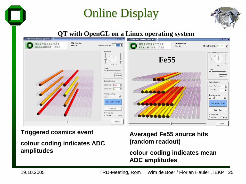
Online DisplayOnline Display
Fe55
QT with OpenGL on a Linux operating system
Triggered cosmics event
colour coding indicates ADC amplitudes
Averaged Fe55 source hits(random readout)
colour coding indicates meanADC amplitudes
19.10.2005 TRD-Meeting, Rom Wim de Boer / Florian Hauler , IEKP 26
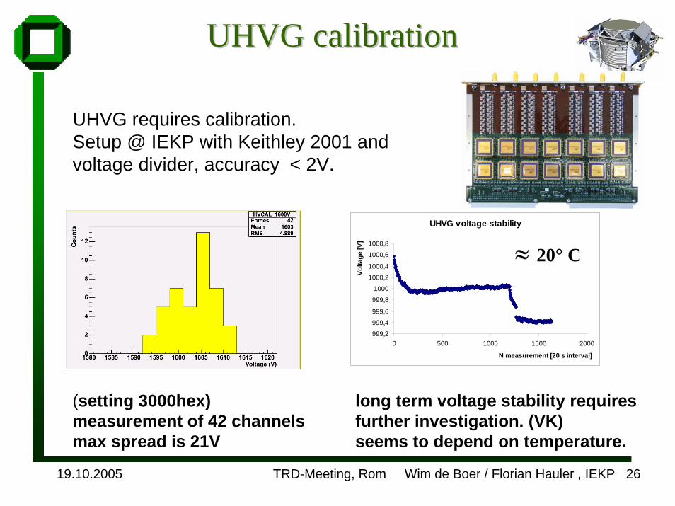
UHVG UHVG calibrationcalibration
UHVG requires calibration. Setup @ IEKP with Keithley 2001 and voltage divider, accuracy < 2V.
UHVG voltage stability
999,2
999,4
999,6
999,8
1000
1000,2
1000,4
1000,6
1000,8
0 500 1000 1500 2000
N measurement [20 s interval]Vo
ltage
[V]
≈ 20° C
(setting 3000hex) measurement of 42 channelsmax spread is 21V
long term voltage stability requiresfurther investigation. (VK) seems to depend on temperature.
19.10.2005 TRD-Meeting, Rom Wim de Boer / Florian Hauler , IEKP 27
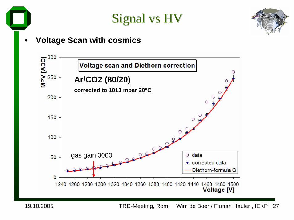
Signal Signal vsvs HVHV• Voltage Scan with cosmics
Ar/CO2 (80/20)corrected to 1013 mbar 20°C
gas gain 3000
19.10.2005 TRD-Meeting, Rom Wim de Boer / Florian Hauler , IEKP 28
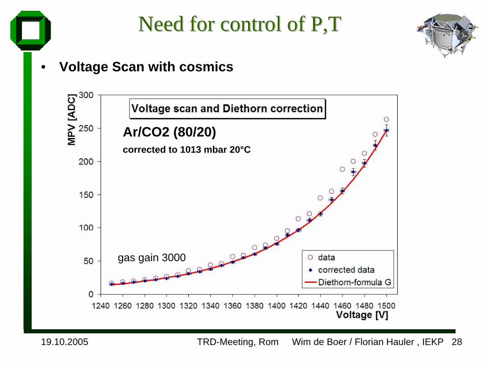
Need for control of Need for control of P,TP,T
• Voltage Scan with cosmics
Ar/CO2 (80/20)corrected to 1013 mbar 20°C
gas gain 3000
19.10.2005 TRD-Meeting, Rom Wim de Boer / Florian Hauler , IEKP 29
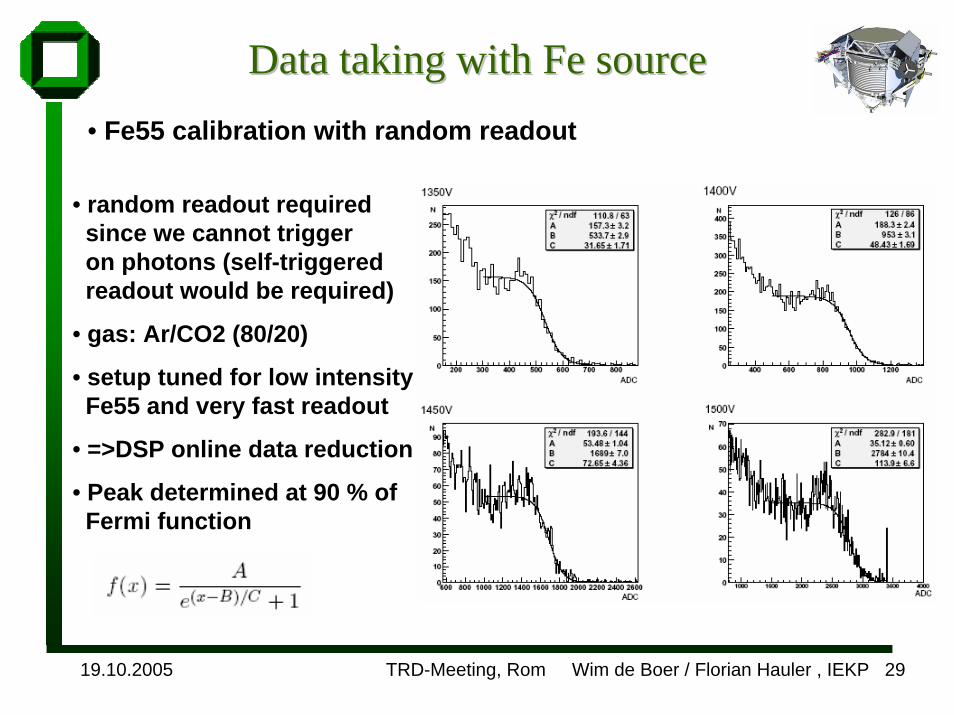
Data taking with Fe sourceData taking with Fe source• Fe55 calibration with random readout
• random readout required since we cannot trigger on photons (self-triggered readout would be required)
• gas: Ar/CO2 (80/20)
• setup tuned for low intensity Fe55 and very fast readout
• =>DSP online data reduction
• Peak determined at 90 % ofFermi function
19.10.2005 TRD-Meeting, Rom Wim de Boer / Florian Hauler , IEKP 30
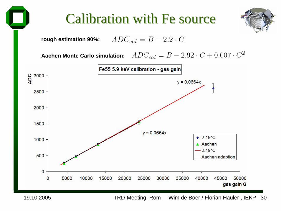
Calibration with Fe sourceCalibration with Fe sourcerough estimation 90%:
Aachen Monte Carlo simulation: